typeseriesbooklet boax --b - all4jet - composants et ... · typeseriesbooklet 8409.11/2-10 boax!--b...
TRANSCRIPT

Type series booklet8409.11/2-10 BOAX!--B
Centred disc butterfly valves
with AMRING! elastomer liner
PS 16 bar:
DN 40 to 200
PS 10 bar:
DN 250 to 1000
Design in accordance with EN 593 and ISO 10631
Applications! General circuits: water, fuel, oil, gas.! O.E.M.! Flow shut--off or regulation functions in the sectors includingwater supply, treatment, distribution, sewage, irrigation.
Working conditions! Temperature: from --10 °Cminimumup to +110 °Cmaximum.! Allowable pressure (PS):
-- 16 bar: DN 40 to 200 at ambient temperature,-- 10 bar: DN 250 to 1000 at ambient temperature.
MaterialsSee page 2.
Design! Semi lug type body (Type 2): DN 40 to 600! Full--lug type body with raised faces (Type 4): DN 40 to 600! Wafer type body (Type 1): DN 650 to 1000
! Flanged body with flat faces (Type 5): DN 200 to 1000! Possible downstream dismantling and end of line for bodiesType 2, 4 and 5.
! Elastomer liner: an extra volumeof rubber, located at the shaftpassages areas, provides by compression between the valve
body and the disc edge a perfect leak--tightness at the shaftpassages.
! Spherical machined disc ensures perfect upstream/downstream sealing: zero leakage visible to the naked eye.
! Face--to--face dimensions in accordance with:ISO 5752 series 20, EN 558--1 series 20.
! Connection standard defined page 9.! Mounting plate meeting the ISO 5211 standards.! Marking in accordance with EN 19.! Valves perfectly tight shut--off (no visible leakage at the naked
eye) in either flow direction, in accordance with the followingstandards: EN 12266--1 leak level A and ISO 5208 category A.
! Design in accordance with EN 593! Body coated with polyurethane paint, thickness 80 "m,colour light blue ref. RAL 5012 conforming with the water
specifications.! Discs in spheroidal graphite cast iron coated with epoxypaint, colour brown ref. RAL 8012, for drinking water.
! The valves meet the safety requirements of the pressureEquipments Directive 97/23/EC (PED) appendix I for liquids
of the group 1 and fluids of the group 2.
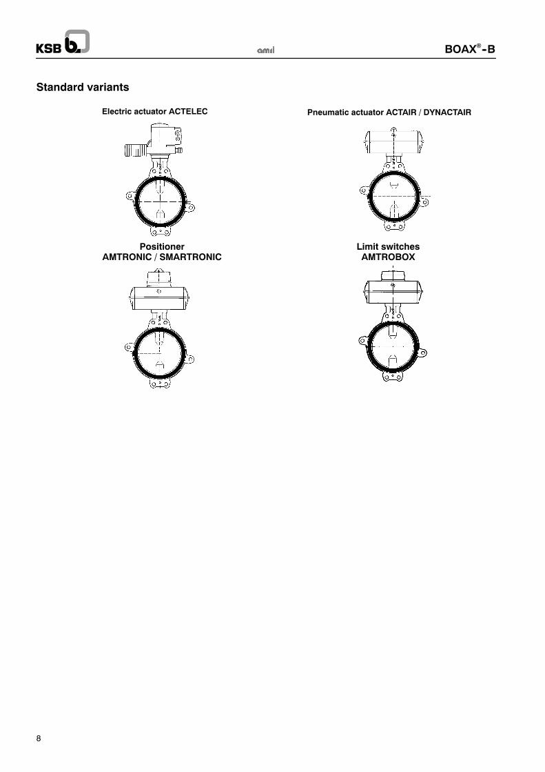
Standard variants! Pneumatic actuator ACTAIR / DYNACTAIR! Electric actuator ACTELEC! Limit switches AMTROBOX! Positioner AMTRONIC / SMARTRONIC! ATEX version in accordance with 94/9/EC directive
Remarks! Actuator selection 8450.11/.-90
! Operating instructions 8449.8/.-10
Data to be supplied when ordering! BOAX--B series valve in accordance with type leaflet8409.11/-10.
! Size.! Working conditions:-- nature of fluid,
-- Pressure,-- Flow,-- Temperature.
! Connection.! Actuation.

BOAX!--B
2
Materials
Body KSB code
Type 2: Spheroidal graphite cast iron JS 1030 DN 40 to 600Type 4: Spheroidal graphite cast iron JS 1030 DN 40 to 600Type 1: Spheroidal graphite cast iron JS 1030 / ASTM A536 gr. 60.40.18 DN 650 to 1000Type 5: Spheroidal graphite cast iron JS 1030 / ASTM A536 gr. 60.40.18 DN 200 to 1000
3g3g3g3g
Shafts KSB code
Stainless steel 1.4029 (13 % Cr) DN 40 to 600Stainless steel 1.4028 (13 % Cr) DN 650 to 1000
6k6k
Disc KSB code
Spheroidal graphite cast iron JS 1030 DN 40 to 1000Stainless steel 1.4308 / ASTM A351 gr.CF8 DN 40 to 1000
3g6g
AMRING! liner KSB code
E.P.D.M drinking water approved. XC
High content nitrile K
Vacuum limits
Vacuum limits
DN NPS Liner mountingMinimum pressure(in absolute bar)
Maximum temperature
40 to 150 1 ½ to 6Without sticking(Standard)
1,33 . 10 --5
(10 --2 torr)90°C
200 to 1000 8 to 40
Without sticking(Standard)
0,3 bar 90°C
200 to 1000 8 to 40With sticking(Option)
1,33 . 10 --5
(10 --2 torr)80°C
BOAX!--B
3
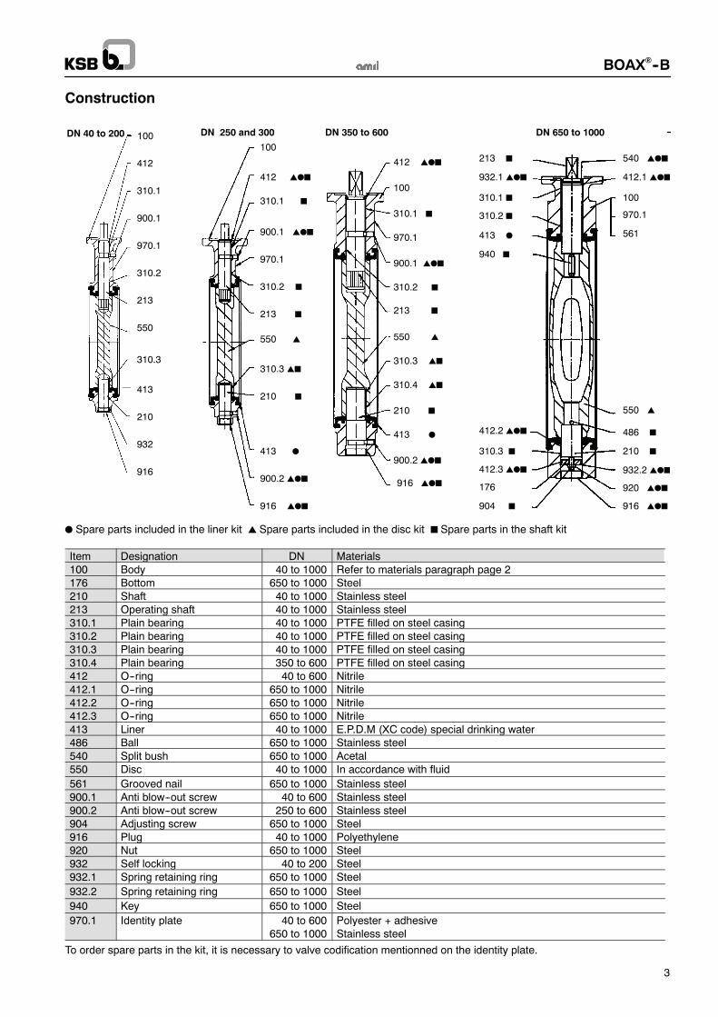
Construction
100
412
310.1
900.1
970.1
310.2
213
550
310.3
413
210
916
100
412 !"#
310.1 #
900.1 !"#
970.1
310.2 #
213 #
550 !
310.3 !#
413 "
210 #
916 !"#
100
412 !"#
310.1 #
900.1 !"#
970.1
310.2 #
213 #
550 !
310.3 !#
413 "
210 #
916 !"#900.2 !"#
310.4 !#
900.2 !"#
DN 250 and 300 DN 350 to 600 DN 650 to 1000
932.1 !"#
100
940 #
412.3 !"#
213 #
550 !
210 #
561
540 !"#
310.1 #
413 "
412.1 !"#
970.1
176
310.2 #
920 !"#
904 #
310.3 #
412.2 !"#
932.2 !"#
486 #
916 !"#
932
DN 40 to 200
" Spare parts included in the liner kit ! Spare parts included in the disc kit # Spare parts in the shaft kit
Item Designation DN Materials100 Body 40 to 1000 Refer to materials paragraph page 2176 Bottom 650 to 1000 Steel210 Shaft 40 to 1000 Stainless steel213 Operating shaft 40 to 1000 Stainless steel310.1 Plain bearing 40 to 1000 PTFE filled on steel casing310.2 Plain bearing 40 to 1000 PTFE filled on steel casing310.3 Plain bearing 40 to 1000 PTFE filled on steel casing310.4 Plain bearing 350 to 600 PTFE filled on steel casing412 O--ring 40 to 600 Nitrile412.1 O--ring 650 to 1000 Nitrile412.2 O--ring 650 to 1000 Nitrile412.3 O--ring 650 to 1000 Nitrile413 Liner 40 to 1000 E.P.D.M (XC code) special drinking water486 Ball 650 to 1000 Stainless steel540 Split bush 650 to 1000 Acetal550 Disc 40 to 1000 In accordance with fluid
561 Grooved nail 650 to 1000 Stainless steel900.1 Anti blow--out screw 40 to 600 Stainless steel900.2 Anti blow--out screw 250 to 600 Stainless steel904 Adjusting screw 650 to 1000 Steel916 Plug 40 to 1000 Polyethylene920 Nut 650 to 1000 Steel932 Self locking 40 to 200 Steel932.1 Spring retaining ring 650 to 1000 Steel
932.2 Spring retaining ring 650 to 1000 Steel
940 Key 650 to 1000 Steel
970.1 Identity plate 40 to 600 Polyester + adhesive650 to 1000 Stainless steel
To order spare parts in the kit, it is necessary to valve codification mentionned on the identity plate.

BOAX!--B
4
Dimensions
e1
e2
h2
h1
h4h3
Flat end s machined in øz or
l1
s
mm
DN NPS
Faceto face
Mounting plateISO 5211
Flat shaft endSquare shaft
endDisc
clearanceDN NPS
l1 h1 h2 n° h4 s øz h3 s h3 e1 e2
40 1 ½ 33 105 51 F05 10 11 14 24 32 450 2 43 109 55 F05 10 11 14 24 33 465 2 ½ 46 136 67 F05 10 11 14 24 55 1180 3 46 142 73 F05 10 11 14 24 71 17100 4 52 163 92 F05 10 14 18 24 90 23125 5 56 176 105 F05 10 14 18 30 119 35150 6 56 194 120 F07 12 14 18 30 144 46200 8 60 222 150 F07 12 19 25 35 196 69250 10 68 255 194 F10 15 19 25 35 249 92300 12 78 282 226 F12 18 22 28 40 297 111350 14 78 335 269 F12 23 25 45 326 127400 16 102 380 298 F14 23 36 55 370 140450 18 114 410 329 F14 23 36 55 422 160500 20 127 440 359 F14 27 36 55 470 178600 24 154 495 439 F16 27 50 65 566 215650 26 165 535 451 F16 26 50 65 620 235700 28 165 560 482 F16 26 50 65 671 260750 30 190 590 513 F16 26 50 65 717 273800 32 190 615 546 F16 26 50 65 769 298900 36 203 665 588 F25 30 60 80 869 3411000 40 216 735 646 F25 30 60 80 970 385

BOAX!--B
5
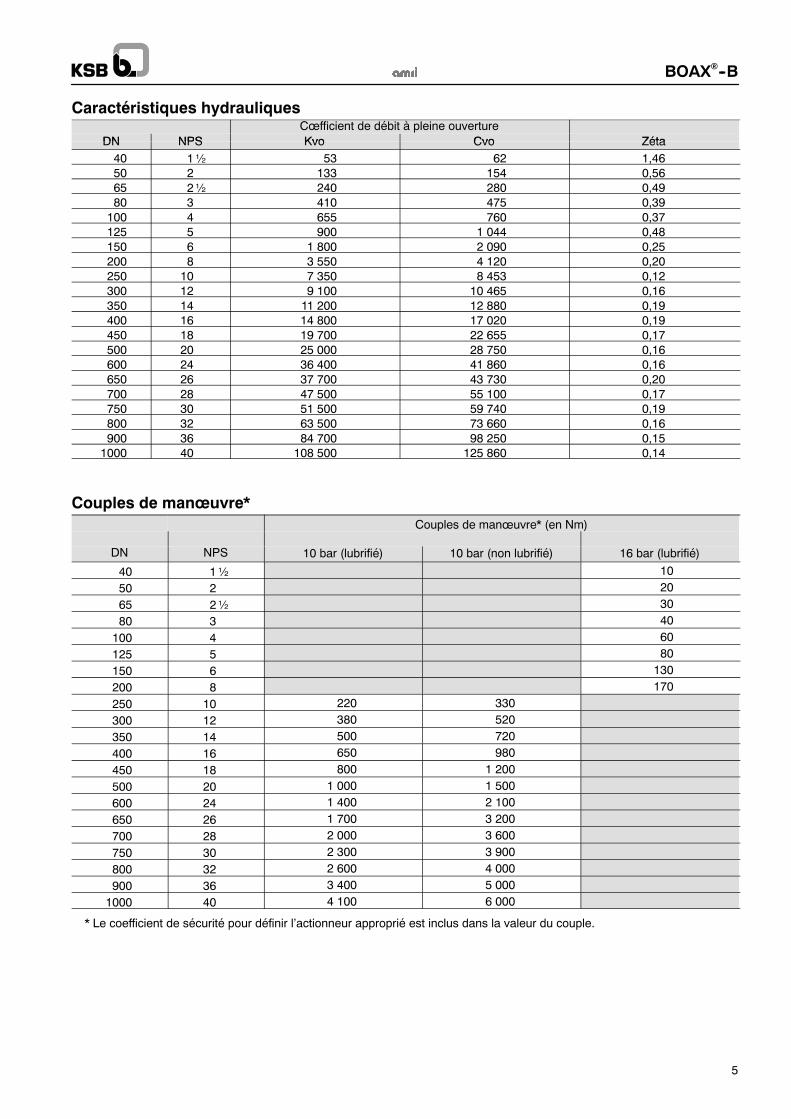
Hydraulic characteristicsFlow coefficient valve in fully open position
DN NPS Kvo Cvo ZetaDN NPS Kvo Cvo Zeta
40 1½ 53 62 1,46
50 2 133 154 0,5665 2½ 240 280 0,49
80 3 410 475 0,39
100 4 655 760 0,37125 5 900 1 044 0,48
150 6 1 800 2 090 0,25
200 8 3 550 4 120 0,20250 10 7 350 8 453 0,12
300 12 9 100 10 465 0,16
350 14 11 200 12 880 0,19400 16 14 800 17 020 0,19
450 18 19 700 22 655 0,17
500 20 25 000 28 750 0,16550 22 31 700 36 455 0,15
600 24 36 400 41 860 0,16
650 26 37 700 43 730 0,20700 28 47 500 55 100 0,17
750 30 51 500 59 740 0,19
800 32 63 500 73 660 0,16900 36 84 700 98 250 0,15
1000 40 108 500 125 860 0,14
Operating torques*
Operating torques* (in Nm)
DN NPS 10 bar (lubricated) 10 bar (non lubricated) 16 bar (lubricated)
40 1½ 10
50 2 20
65 2½ 30
80 3 40
100 4 60
125 5 80
150 6 130
200 8 170
250 10 220 330
300 12 380 520
350 14 500 720
400 16 650 980
450 18 800 1 200
500 20 1 000 1 500
600 24 1 400 2 100
650 26 1 700 3 200
700 28 2 000 3 600
750 30 2 300 3 900
800 32 2 600 4 000
900 36 3 400 5 000
1000 40 4 100 6 000
* The safety cœfficient to define the adapted actuator is included in the torque value.
BOAX!--B
6
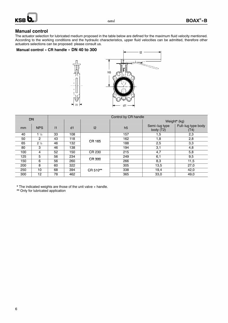
Manual controlThe actuator selection for lubricated medium proposed in the table below are defined for the maximum fluid velocity mentioned.According to the working conditions and the hydraulic characteristics, upper fluid velocities can be admitted, therefore otheractuators selections can be proposed: please consult us.
Manual control -- CR handle -- DN 40 to 300
d1
h5
l2
l1
DNControl by CR handle
DNWeight* (kg)
mm NPS l1 d1 l2 h5Semi--lug typebody (T2)
Full--lug type body(T4)
40 1 ½ 33 108 157 1,5 2,3
50 2 43 118CR 165
162 1,8 2,8
65 2 ½ 46 132CR 165
188 2,5 3,3
80 3 46 138 194 3,1 4,8
100 4 52 150 CR 230 215 4,7 5,8
125 5 56 234CR 300
249 6,1 9,5
150 6 56 260CR 300
266 8,3 11,5
200 8 60 322 305 13,5 27,0
250 10 68 394 CR 510** 338 19,4 42,0
300 12 78 462CR 510
365 33,0 49,0
* The indicated weights are those of the unit valve + handle.** Only for lubricated application

BOAX!--B
7
MN and MR reducers -- 10 bar version
Maxi.fluid Action-
A B C D Ø E h2Weight
MR
DN NPS
fluidvelocity(m/s)
Actionneur
A(mm)
B(mm)
C(mm)
D(mm)
Ø E(mm)
h2(mm)
MR(kg)
Lubricated medium250 10 MN 25 64 202 60 50 225 361 2,3300 12
3 0MN 40 70 225 60 60 225 422 3,4
350 143,0
483400 16 MN 80 90 245 70 75 225 538 4,6450 18
MN 80 90 245 70 75 225557
4,6
500 20 2,5 MR 100 86 233 88 88 350 677 15,0600 24
2,5743
650 26 MR 200 120 270 108 117 350 78324 0
700 282 0
MR 200 120 270 108 117 350808
24,0
h2 750 302,0
860h2
800 32MR 400 229 332 115 125 350
88558 0
900 361 5
MR 400 229 332 115 125 350898
58,0
1000 401,5
1 005Non lubricated medium
250 10 MN 40 70 225 60 60 225 393 3,4300 12
3 0 MN 80 90 245 70 75 225429
4 6350 14
3,0 MN 80 90 245 70 75 225483
4,6
400 16 MR 100 86 233 88 88 350 617 15,0450 18 658500 20 2,5 MR 200 120 270 108 117 350 688 24,0600 24
2,5 MR 200 120 270 108 117 350743
24,0
650 26 805700 28
2 0 MR 400 229 332 115 125 350830
58 0750 30
2,0 MR 400 229 332 115 125 350860
58,0
800 32 885900 36
1 5 MR 600 271 511 155 140 6001074
105 01000 40
1,5 MR 600 271 511 155 140 6001144
105,0
MN reducers -- 16 bar version
AB D Maxi.
fluidActuator A B C D Ø E h2
WeightMR
A
CDN NPS
fluidvelocity(m/s)
Actuator A(mm)
B(mm)
C(mm)
D(mm)
Ø E(mm)
h2(mm)
MR(kg)
Ø E40 1½ 203
Ø E 50 2 208
h2 65 2½MN 12 49 135 42 40 140
2341 6h2
80 33 0
MN 12 49 135 42 40 140240
1,6
100 43,0
261
125 5 275
150 6MN 25 64 202 60 50 225
3382 3
200 8MN 25 64 202 60 50 225
3662,3
BOAX!--B
8
Standard variants
Electric actuator ACTELEC Pneumatic actuator ACTAIR / DYNACTAIR
PositionerAMTRONIC / SMARTRONIC
Limit switchesAMTROBOX
BOAX!--B
9
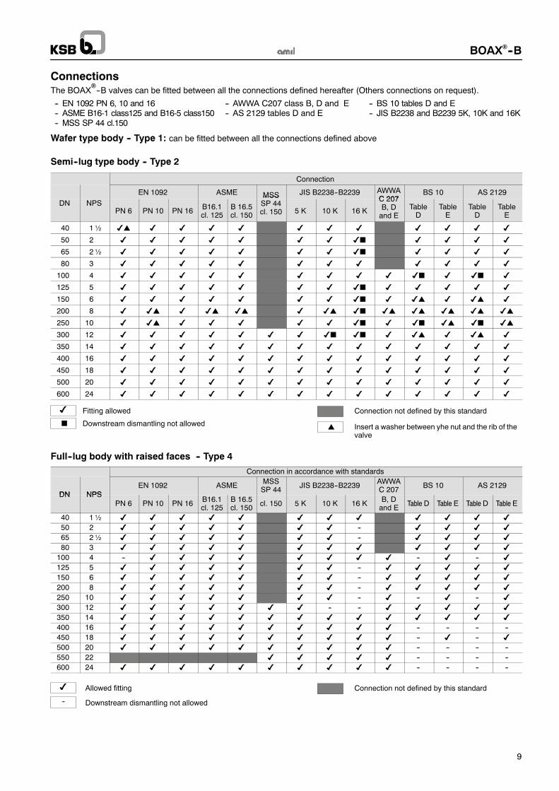
ConnectionsThe BOAX!--B valves can be fitted between all the connections defined hereafter (Others connections on request).
-- EN 1092 PN 6, 10 and 16-- ASME B16-1 class125 and B16-5 class150-- MSS SP 44 cl.150
-- AWWA C207 class B, D and E-- AS 2129 tables D and E
-- BS 10 tables D and E-- JIS B2238 and B2239 5K, 10K and 16K
Wafer type body -- Type 1: can be fitted between all the connections defined above
Semi--lug type body -- Type 2
Connection
EN 1092 ASME MSS JIS B2238--B2239 AWWAC 207
BS 10 AS 2129
DN NPSPN 6 PN 10 PN 16
B16.1cl. 125
B 16.5cl. 150
MSSSP 44cl. 150 5 K 10 K 16 K
C 207B, Dand E
TableD
TableE
TableD
TableE
40 1½ $! $ $ $ $ $ $ $ $ $ $ $
50 2 $ $ $ $ $ $ $ $# $ $ $ $
65 2½ $ $ $ $ $ $ $ $# $ $ $ $
80 3 $ $ $ $ $ $ $ $ $ $ $ $
100 4 $ $ $ $ $ $ $ $ $ $# $ $# $
125 5 $ $ $ $ $ $ $ $# $ $ $ $ $
150 6 $ $ $ $ $ $ $ $# $ $! $ $! $
200 8 $ $! $ $! $! $ $! $# $! $! $! $! $!
250 10 $ $! $ $ $ $ $ $# $ $# $! $# $!
300 12 $ $ $ $ $ $ $ $# $# $ $! $ $! $
350 14 $ $ $ $ $ $ $ $ $ $ $ $ $ $
400 16 $ $ $ $ $ $ $ $ $ $ $ $ $ $
450 18 $ $ $ $ $ $ $ $ $ $ $ $ $ $
500 20 $ $ $ $ $ $ $ $ $ $ $ $ $ $
600 24 $ $ $ $ $ $ $ $ $ $ $ $ $ $
$ Fitting allowed
Downstream dismantling not allowed
Connection not defined by this standard
Insert a washer between yhe nut and the rib of thevalve
!#
Full--lug body with raised faces -- Type 4
Connection in accordance with standards
DN NPSEN 1092 ASME
MSSSP 44
JIS B2238--B2239AWWAC 207
BS 10 AS 2129DN NPS
PN 6 PN 10 PN 16B16.1cl. 125
B 16.5cl. 150
cl. 150 5 K 10 K 16 KB, Dand E
Table D Table E Table D Table E
40 1½ $ $ $ $ $ $ $ $ $ $ $ $
50 2 $ $ $ $ $ $ $ -- $ $ $ $
65 2½ $ $ $ $ $ $ $ -- $ $ $ $
80 3 $ $ $ $ $ $ $ $ $ $ $ $
100 4 -- $ $ $ $ $ $ $ $ -- $ -- $
125 5 $ $ $ $ $ $ $ -- $ $ $ $ $
150 6 $ $ $ $ $ $ $ -- $ $ $ $ $
200 8 $ $ $ $ $ $ $ -- $ $ $ $ $
250 10 $ $ $ $ $ $ $ -- $ -- $ -- $
300 12 $ $ $ $ $ $ $ -- -- $ $ $ $ $
350 14 $ $ $ $ $ $ $ $ $ $ $ $ $ $
400 16 $ $ $ $ $ $ $ $ $ $ -- -- -- --
450 18 $ $ $ $ $ $ $ $ $ $ -- $ -- $
500 20 $ $ $ $ $ $ $ $ $ $ -- -- -- --
550 22 $ $ $ $ $ -- -- -- --
600 24 $ $ $ $ $ $ $ $ $ $ -- -- -- --
$
--
Allowed fitting
Downstream dismantling not allowed
Connection not defined by this standard

BOAX!--B
10
Flanged body with flat faces -- Type 5
Connection
DN NPS
EN 1092 ASMEMSSSP 44
JIS B2238--B2239AWWAC 207
BS 10 AS 2129
DN NPS
PN 6 PN 10 PN 16B16.1cl. 125
B 16.5cl. 150
cl. 150 5 K 10 K 16 KB, Dand E
TableD
TableE
TableD
TableE
200 8 $ $ $ $ $ $ $ $ $ $ $ $ $
250 10 $ $ $ $ $ $ $ $# $ -- $ -- $
300 12 $ $ $ $ $ $ $ $ $ $ $ $ $ $
350 14 $ $ $ $ $ $ $ $ $ $ $ $ $ $
400 16 $ $ $ $ $ $ $ $ $ $ $ $ $ $
450 18 $ $ $ $ $ $ $ $ -- $ $ $ $ $
500 20 $ $ $ $ $ $ $ $ $ $ $ $ $ $
600 24 $ $ $ $ $ $ $ $ $ $ $ $ $ $
650 24 $" $" $" % $"
700 28 $" $" $" $" $" $" % $" $" $" $" $"
750 30 $" $" $" $" % $" $" $" $" $"
800 32 $" $" $" $" $" $" % $" $" $"
900 36 $" $" $" $" $" # $" -- $" $" $" $" $"
1000 40 $" $" $" $" # $" -- $" $" $" $" $"
$
--
Fitting allowed
Fitting not allowed
Flange fitting allowed
# Downstream dismantling not allowed
"
Connection not defined by this standard
% Please consult us
End of line and downstream dismantling
The BOAX!--T valves type 1, 2, 4 and 5 are fitted between pipe flanges, by tie--rod, without gasket.
They are bi--directional and can be mounted in all positions.Use as end of line and downstreamdismantling of the standard valves at room temperature for DNand the differential pressure (#PS)defined hereafter:
Gas or liquids* Liquids*
Hazardous** Non hazardous** hazardous** non hazardous**
All sizes: not authorized
Sizes$ 200:#PS = 10 bar maxiSizes 250 to 600:#PS = 7 bar maxi
Sizes $ 200:#PS = 10 bar maxiSizes 250 to 600:#PS = 7 bar maxi
Sizes $ 200:#PS = 12 bar maxiSizes 250 to 600:#PS = 7 bar maxi
* Liquids having a vapour pressure at the maximum allowable temperature of not more than 0,5 bar above atmospheric pressure1013 mbar.
** Fluids hazardous and not hazardous according to PED.NB: A valve fitted at the end of a pipe with a blind flange downstream is not to be considered as an end of pipe service.
Downstream dismantling End of line mounting
Dismantling phase:working successively ondiametrically oppositetie--rods.
BOAX!--B
11
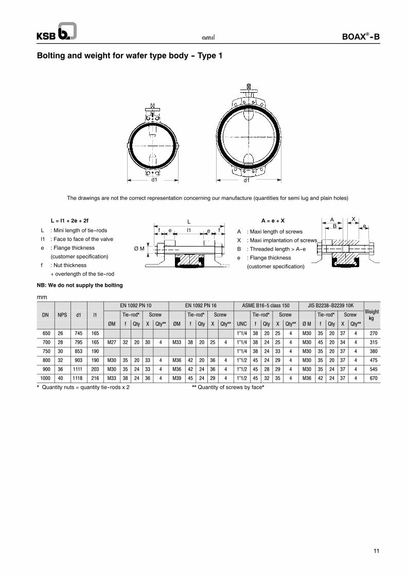
Bolting and weight for wafer type body -- Type 1
L : Mini length of tie--rods
l1 : Face to face of the valve
e : Flange thickness
(customer specification)
f : Nut thickness
+ overlength of the tie--rod
A : Maxi length of screws
X : Maxi implantation of screws
B : Threaded length > A--e
e : Flange thickness
(customer specification)
AB e
d1
L = l1 + 2e + 2f
The drawings are not the correct representation concerning our manufacture (quantities for semi lug and plain holes)
f l1e e f
L
Ø M
XA = e + X
d1
NB: We do not supply the bolting
mm
EN 1092 PN 10 EN 1092 PN 16 ASME B16--5 class 150 JIS B2238--B2239 10KWeight
DN NPS d1 l1 Tie--rod* Screw Tie--rod* Screw Tie--rod* Screw Tie--rod* ScrewWeight
kgØM f Qty X Qty** ØM f Qty X Qty** UNC f Qty X Qty** Ø M f Qty X Qty**
kg
650 26 745 165 1”1/4 38 20 25 4 M30 35 20 37 4 270
700 28 795 165 M27 32 20 30 4 M33 38 20 25 4 1”1/4 38 24 25 4 M30 45 20 34 4 315
750 30 853 190 1”1/4 38 24 33 4 M30 35 20 37 4 380
800 32 903 190 M30 35 20 33 4 M36 42 20 36 4 1”1/2 45 24 29 4 M30 35 20 37 4 475
900 36 1111 203 M30 35 24 33 4 M36 42 24 36 4 1”1/2 45 28 29 4 M30 35 24 37 4 545
1000 40 1118 216 M33 38 24 36 4 M39 45 24 29 4 1”1/2 45 32 35 4 M36 42 24 37 4 670
* Quantity nuts = quantity tie--rods x 2 ** Quantity of screws by face*

BOAX!--B
12
d1d1 d1
The drawings are not the correct representation concerning our manufacture (quantities for semi lug and plain holes)
Bolting and weight for semi--lug type body -- Type 2
NB: We do not supply the bolting
L : Mini length of tie--rods
l1 : Face to face of the valve
e : Flange thickness
(customer specification)
f : Nut thickness
+ overlength of the tie--rod
A : Maxi length of screws
X : Maxi implantation of screws
B : Threaded length > A--e
e : Flange thickness
(customer specification)
AB e
L = l1 + 2e + 2f
f l1e e f
L
Ø M
XA = e + X
mm
EN 1092 PN 10 EN 1092 PN 16 ASME B16--5 class 150 JIS B2238--B2239 10KWeight
DN NPS d1 l1 Tie--rod* Screw Tie--rod* Screw Tie--rod* Screw Tie--rod* ScrewWeight
kgØM f Qty X Qty** ØM f Qty X Qty** UNC f Qty X Qty** Ø M f Qty X Qty**
kg
40 1 ½ 108 33 M16 20 4 M16 20 4 1/2” 17 4 M16 20 4 1,1
50 2 118 43 M16 20 4 M16 20 4 5/8” 20 4 M16 20 4 1,3
65 2 ½ 132 46 M16 20 4 M16 20 4 5/8” 20 4 M16 20 4 1,9
80 3 138 46 M16 20 8 M16 20 8 5/8” 20 4 M16 20 8 2,5
100 4 150 52 M16 20 8 M16 20 8 5/8” 20 8 M16 20 8 3,9
125 5 234 56 M16 20 8 M16 20 8 3/4” 24 8 M20 24 8 4,7
150 6 260 56 M20 24 8 M20 24 8 3/4” 24 8 M20 24 8 6,9
200 8 322 60 M20 24 8 M20 24 12 3/4” 24 8 M20 24 12 10,5
250 10 394 68 M20 24 12 M24 29 12 7/8” 29 12 M22 26 12 16,4
300 12 462 78 M20 24 12 M24 29 12 7/8” 29 12 M22 26 16 30,0
350 14 538 78 M20 24 10 20 6 M24 29 10 24 6 1” 32 6 27 6 M22 26 10 22 6 60,0
400 16 604 102 M24 29 10 24 6 M27 32 10 27 6 1” 32 10 27 6 M24 29 10 24 6 80,0
450 18 656 114 M24 29 14 24 6 M27 32 14 27 6 1”1/8 35 10 30 6 M24 29 12 24 6 110,0
500 20 716 127 M24 29 12 24 8 M30 35 12 30 8 1”1/8 35 12 30 8 M24 29 12 24 8 145,0
600 24 836 154 M27 32 10 27 10 M33 38 10 33 10 1”1/4 38 10 32 10 M30 35 14 30 10 220,0
* Quantity nuts = quantity tie--rods x 2 ** Quantity of screws by face*
BOAX!--B
13
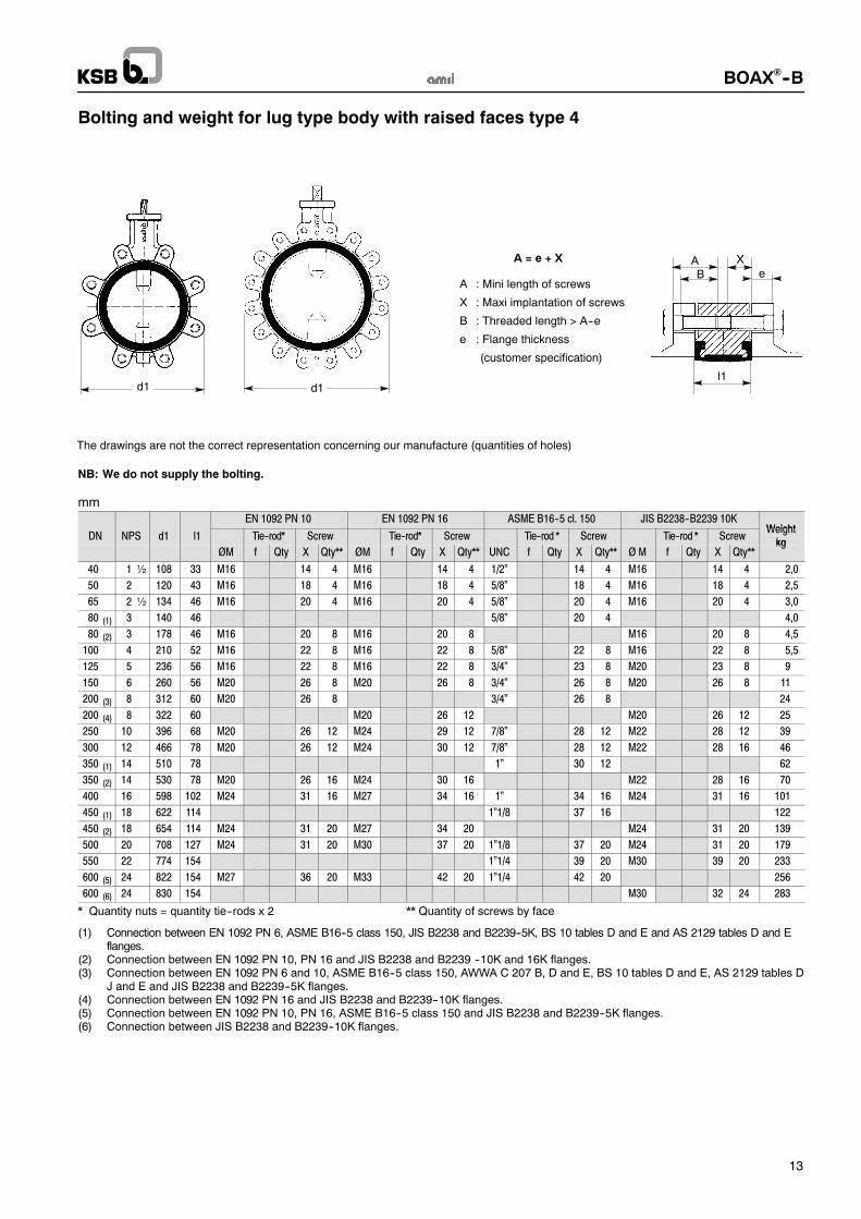
Bolting and weight for lug type body with raised faces type 4
The drawings are not the correct representation concerning our manufacture (quantities of holes)
d1d1
AB e
XA = e + X
l1
A : Mini length of screws
X : Maxi implantation of screws
B : Threaded length > A--e
e : Flange thickness
(customer specification)
NB: We do not supply the bolting.
mmEN 1092 PN 10 EN 1092 PN 16 ASME B16--5 cl. 150 JIS B2238--B2239 10K
WeightDN NPS d1 l1 Tie--rod* Screw Tie--rod* Screw Tie--rod * Screw Tie--rod * Screw
Weightkg
ØM f Qty X Qty** ØM f Qty X Qty** UNC f Qty X Qty** Ø M f Qty X Qty**kg
40 1 ½ 108 33 M16 14 4 M16 14 4 1/2” 14 4 M16 14 4 2,0
50 2 120 43 M16 18 4 M16 18 4 5/8” 18 4 M16 18 4 2,5
65 2 ½ 134 46 M16 20 4 M16 20 4 5/8” 20 4 M16 20 4 3,0
80 (1) 3 140 46 5/8” 20 4 4,0
80 (2) 3 178 46 M16 20 8 M16 20 8 M16 20 8 4,5
100 4 210 52 M16 22 8 M16 22 8 5/8” 22 8 M16 22 8 5,5
125 5 236 56 M16 22 8 M16 22 8 3/4” 23 8 M20 23 8 9,0
150 6 260 56 M20 26 8 M20 26 8 3/4” 26 8 M20 26 8 11,0
200 (3) 8 312 60 M20 26 8 3/4” 26 8 24,0
200 (4) 8 322 60 M20 26 12 M20 26 12 25,0
250 10 396 68 M20 26 12 M24 29 12 7/8” 28 12 M22 28 12 39,0
300 12 466 78 M20 26 12 M24 30 12 7/8” 28 12 M22 28 16 46,0
350 (1) 14 510 78 1” 30 12 62,0
350 (2) 14 530 78 M20 26 16 M24 30 16 M22 28 16 70,0
400 16 598 102 M24 31 16 M27 34 16 1” 34 16 M24 31 16 101,0
450 (1) 18 622 114 1”1/8 37 16 122,0
450 (2) 18 654 114 M24 31 20 M27 34 20 M24 31 20 139,0
500 20 708 127 M24 31 20 M30 37 20 1”1/8 37 20 M24 31 20 179,0
550 22 774 154 1”1/4 39 20 M30 39 20 233,0
600 (5) 24 822 154 M27 36 20 M33 42 20 1”1/4 42 20 256,0
600 (6) 24 830 154 M30 32 24 283,0
* Quantity nuts = quantity tie--rods x 2 ** Quantity of screws by face
(1) Connection between EN 1092 PN 6, ASME B16--5 class 150, JIS B2238 and B2239--5K, BS 10 tables D and E and AS 2129 tables D and Eflanges.
(2) Connection between EN 1092 PN 10, PN 16 and JIS B2238 and B2239 --10K and 16K flanges.(3) Connection between EN 1092 PN 6 and 10, ASME B16--5 class 150, AWWA C 207 B, D and E, BS 10 tables D and E, AS 2129 tables D
J and E and JIS B2238 and B2239--5K flanges.(4) Connection between EN 1092 PN 16 and JIS B2238 and B2239--10K flanges.(5) Connection between EN 1092 PN 10, PN 16, ASME B16--5 class 150 and JIS B2238 and B2239--5K flanges.(6) Connection between JIS B2238 and B2239--10K flanges.
BOAX!--B
14
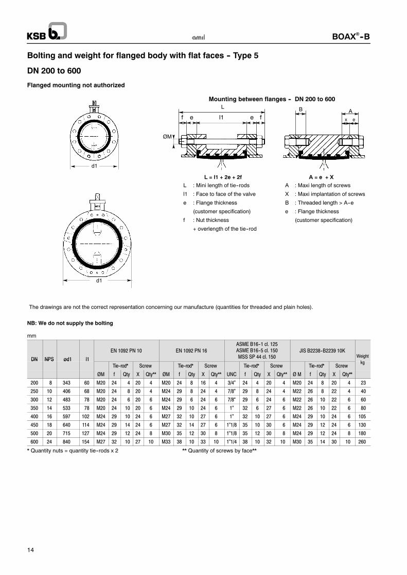
Bolting and weight for flanged body with flat faces -- Type 5
DN 200 to 600
Flanged mounting not authorized
L
fel1ef
ØM
The drawings are not the correct representation concerning our manufacture (quantities for threaded and plain holes).
d1
d1
L = l1 + 2e + 2f
Mounting between flanges -- DN 200 to 600
A = e + X
A
x e
B
L : Mini length of tie--rods
l1 : Face to face of the valve
e : Flange thickness
(customer specification)
f : Nut thickness
+ overlength of the tie--rod
A : Maxi length of screws
X : Maxi implantation of screws
B : Threaded length > A--e
e : Flange thickness
(customer specification)
NB: We do not supply the bolting
mm
DN NPS ød1 l1
EN 1092 PN 10 EN 1092 PN 16ASME B16--1 cl. 125ASME B16--5 cl. 150MSS SP 44 cl. 150
JIS B2238--B2239 10KWeight
kDN NPS ød1 l1
Tie--rod* Screw Tie--rod* Screw Tie--rod* Screw Tie--rod* Screwkg
ØM f Qty X Qty** ØM f Qty X Qty** UNC f Qty X Qty** Ø M f Qty X Qty**
200 8 343 60 M20 24 4 20 4 M20 24 8 16 4 3/4” 24 4 20 4 M20 24 8 20 4 23
250 10 406 68 M20 24 8 20 4 M24 29 8 24 4 7/8” 29 8 24 4 M22 26 8 22 4 40
300 12 483 78 M20 24 6 20 6 M24 29 6 24 6 7/8“ 29 6 24 6 M22 26 10 22 6 60
350 14 533 78 M20 24 10 20 6 M24 29 10 24 6 1” 32 6 27 6 M22 26 10 22 6 80
400 16 597 102 M24 29 10 24 6 M27 32 10 27 6 1” 32 10 27 6 M24 29 10 24 6 105
450 18 640 114 M24 29 14 24 6 M27 32 14 27 6 1”1/8 35 10 30 6 M24 29 12 24 6 130
500 20 715 127 M24 29 12 24 8 M30 35 12 30 8 1”1/8 35 12 30 8 M24 29 12 24 8 180
600 24 840 154 M27 32 10 27 10 M33 38 10 33 10 1”1/4 38 10 32 10 M30 35 14 30 10 260
* Quantity nuts = quantity tie--rods x 2 ** Quantity of screws by face**

BOAX!--B
15
Bolting and weight for flanged body with flat faces -- Type 5
DN 650 to 1000
Flanged mounting authorized for the differential maximum pressure for 10 bar
A
x e
B
L
fel1ef
ØM
The drawings are not the correct representation concerning
our manufacture (quantities for threaded and plain holes).
d1
d1
L = l1 + 2e + 2f
Mounting between flanges -- DN 650 to 1000
Flanged mounting -- DN 650 to 1000
A = e + X
A
x e
B
Bolting definition: Please, consult us
C
C
L : Mini length of tie--rods
l1 : Face to face of the valve
e : Flange thickness
(customer specification)
f : Nut thickness
+ overlength of the tie--rod
A : Maxi length of screws
X : Maxi implantation of screws
B : Threaded length > A--e
e : Flange thickness
(customer specification)
NB: We do not supply the bolting
mm
DN NPS ød1 l1 C
EN 1092 PN 10 EN 1092 PN 16ASME B16--1 cl. 125ASME B16--5 cl. 150MSS SP 44 cl. 150
JIS B2238--B2239 10KWeight
kgDN NPS ød1 l1 C
Tie--rod* Screw Tie--rod* Screw Tie--rod* Screw Tie--rod* Screwkg
ØM f Qty X Qty** ØM f Qty X Qty** UNC f Qty X Qty** Ø M f Qty X Qty**
650 26 835 (1) 165 31 M30 35 20 37 4 285
650 26 869 (2) 165 31 1”1/4 38 20 25 4 305
700 28 895 (1) 165 32.5 M27 32 20 27 4 M30 35 20 37 4 330
700 28 925 (3) 165 32.5 M33 38 20 25 4 1”1/4 38 24 25 4 350
750 30 965 (1) 190 33.5 M30 35 20 37 4 330
750 30 985 (3) 190 33.5 1”1/4 38 24 33 4 350
800 32 1 015 (1) 190 35 M30 35 20 30 4 M30 35 24 37 4 505
800 32 1 075 (3) 190 35 M36 42 20 36 4 1”1/2 45 24 29 4 525
900 36 1 115 (1) 203 37.5 M30 35 24 30 4 M30 35 24 37 4 590
900 36 1 160 (3) 203 37.5 M36 42 24 36 4 1”1/2 45 28 29 4 620
1000 40 1 230 (1) 216 40 M33 38 24 33 4 M36 42 24 37 4 740
1000 40 1 275 (3) 216 40 M39 45 24 29 4 1”1/2 45 32 35 4 780
* Quantity nuts = quantity tie--rods x 2 ** Quantity of screws by face**
(1) Connection between EN 1092 PN 6, 10, JIS B2238 and B2239--5K and 10K flanges.(2) Connection between EN 1092 PN 16, MSS SP 44 class 150, ASME B 16--1 class 125 flanges.(3)Connection between EN1092PN16,MSSSP44 class 150, ASMEB16--1 class 125, AS2129 classDandEandBS10 classDandE flanges.

BOAX!--B
16
Flanging dimensions
BOAX!--B valves are designed for assembly between any type of flanges and connection standards currently used.The linerallows directly the tightness concerning the flanges. It is necessary to verify the general compatibility of the connection by checkingagainst the dimensions shown in the table below.The flanging dimensions mentioned in this table are the same for all types body.
ø2a ø2bø1ø3
ø5
ø4 ø610
20
! ø2a and ø3: diameter on the supporting area of the flange face.! ø2b: external diameter of the butt--weld ends with lapped pipe end according to standards DIN 2642 and NFE 29--251.
mm
DN NPS
Opti-mumdia.
Max. dia tolerated Min. dia.tolerated
face of flange
Min. dia. 10 mmfrom face offlange
Min. dia. 20 mmfromface offlange
Min. dia.tolerated ofshoulder ofraised faceflange
ø1 ø2a ø2b ø3 ø4 ø5 ø6
40 1 ½ 40 54,0 49 32 ------ ------ 77
50 2 49 63,0 61 33 ------ ------ 86
65 2 ½ 65 80,0 77 55 13 ------ 107
80 3 77 93,0 89 71 50 ------ 121
100 4 96 116,0 115 90 74 40 141
125 5 123 141,5 140 119 107 87 171
150 6 146 170,5 * 169 144 134 120 196
200 8 196 222,0 * 220 196 189 178 250
250 10 249 276,5 * 273 249 243 234 306
300 12 298 327,5 * 324 297 291 283 358
350 14 330 361,0 356 326 321 314 399
400 16 380 412,0 407 370 366 358 452
450 18 430 463,0 457 422 416 409 505
500 20 480 515,0 508 470 464 457 558
600 24 580 617,0 610 566 560 554 664
650 26 630 668,0 620 614 608 723
700 28 680 718,0 671 666 660 773
750 30 680 718,0 671 666 660 773
800 32 780 820,0 769 764 758 880
900 36 880 924,0 869 864 859 987
1000 40 980 1 027,0 970 965 960 1 094
* Please check the body is well centred between the tie--rods.
NB:Direct fitting on rubber coated flange andwith dilatation joint is not authorized.Please, consult us.
Dilatation jointRubber coated flange

BOAX!--B
17
Notes

BOAX!--B
18
Notes

BOAX!--B
19
Notes

KSB S.A.S
4, allée des Barbanniers ! 92635 Gennevilliers Cedex (France)
Tel. : +33 1 41 47 75 00 ! Fax : +33 1 41 47 75 10 ! www.ksb.com
BOAX!--B
Product features -- to our customers’ benefit
!
!!
!
!
!
!
!
!
!
!
AMRING ! liner drinking waterapproved
Disc position index
Mounting plate according to
ISO 5211 standard
Preserved external internal
tightness when the actuatoris taken off
Bearing in reinforced
PTFE on steel support
Shaft passage tightness
Perfect tightness at shaftpassage obtained by the
compression of the liner
collar on the disc spherical
Downstream/upstream
tightnessDisc machined spherical for
ensuring a perfect tightness
downstream/upstream
Driving shaft/disc without
contact with the fluid,by splines or keys
Flanges tightness
Special design to obtain atotale tightness at flanges by
compression
Face to face
of the body according to thestandards ISO 5752 series 20
and EN 558 series 20
Anti blow--out
screw of the shaft
Anti blow--out
screw of the shaft
11.01.07
Thisleafletisnotcontractual
andmaybeamendedwithoutnotice.
8409.11/2--10

Livret technique8409.11/5-20 BOAX!--B
Robinet à papillon centré
à étanchéité élastomère AMRING!
PS 16 bar :
DN 40 à 200
PS 10 bar :
DN 250 à 1000
Conception selon normes EN 593 et ISO 10631
Applications! Circuits généraux sur eau, fioul, huile et gaz.! Ensembliers.! Sectionnement et régulation dans le domaine de l’eau, en
adduction, traitement, distribution, assainissement,irrigation.
Conditions de service! Température : de --10 °C minimum à +110 °C maximum.
! Pression admissible (PS) :-- 16 bar : DN 40 à 200 à la température ambiante,-- 10 bar : DN 250 à 1000 à la température ambiante.
MatériauxVoir page 2.
Conception standard! Corps à oreilles de démontage (Type 2) : DN 40 à 600! Corps à bossages taraudés à faces surélevées (Type 4) :
DN 40 à 600! Corps annulaires à faces planes (Type 1) : DN 650 à 1000! Corps à brides à faces planes (Type 5) : DN 150 à 1000! Démontage aval et montage en bout de ligne pour les corps
types 2, 4 et 5 possibles.
! Manchette en élastomère pourvue d’une surcompressionvolumique aux passages d’arbres assurant une parfaiteétanchéité d’enceinte.
! Obturateur usiné sphérique garantissant une parfaiteétanchéité amont/aval : aucune fuite visible à l’œil nu.
! Barrière thermique entre le robinet et la poignée.! Ecartement face--à--face suivant normes :
ISO 5752 série 20, EN 558--1 série 20.! Raccordement suivant normes définies page 9.
! Embase de raccordement d’actionnement suivant normeISO 5211.
! Marquage conforme à la norme EN 19.! Robinets parfaitement étanches (aucune fuite visible à l’œil nu )
dans les deux sens d’écoulement suivant normes :EN 12266--1 taux de fuite A et ISO 5208 catégorie A.
! Conception conforme à la norme EN 593.! Exempt d’amiante, de CFC, de PCB et de toute substance
altérant l’adhérence de la peinture.! Corps revêtus d’une peinture polyuréthane épaisseur 80 "m,
couleur bleu clair réf. RAL 5012 conforme aux spécifications
du marché de l’eau.! Obturateurs en fonte à graphite sphéroïdal revêtus d’une
peinture époxy marron RAL 8012, agréée eau potable.! Les robinets sont conformes aux exigences de sécurité de
l’annexe I de la Directive Equipements Sous Pression
97/23/EC (DESP) pour les liquides du groupe 1 et les fluidesdu groupe 2.
Variantes standards! Actionneur pneumatique ACTAIR / DYNACTAIR! Actionneur électrique ACTELEC! Contact de fin de course AMTROBOX! Positionneur AMTRONIC / SMARTRONIC
Documentations complémentaires! Choix de l’actionneur 8450.11/.-90
! Instructions de service 8411.801/.-90
Indications à fournir à la commande! Robinet BOAX--B suivant livret technique 8409.11/.-20.! Diamètre nominal.! Conditions de service : fluide véhiculé, pression, débit,
température.! Raccordement.
! Actionnement.

BOAX!--B
2
Matériaux
Corps Code KSB
Type 2 : Fonte à graphite sphéroïdal JS 1030 DN 40 à 600Type 4 : Fonte à graphite sphéroïdal JS 1030 DN 40 à 600Type 1 : Fonte à graphite sphéroïdal JS 1030 / ASTM A536 gr. 60.40.18 DN 650 à 1000Type 5 : Fonte à graphite sphéroïdal JS 1030 / ASTM A536 gr. 60.40.18 DN 200 à 1000
3g3g3g3g
Arbre -- Axe Code KSB
Acier inoxydable 1.4029 (13 % Cr) DN 40 à 1000 6k
Obturateur Code KSB
Fonte à graphite sphéroïdal JS 1030 DN 40 à 1000Acier inoxydable 1.4308 / ASTM A351 gr.CF8 DN 40 à 1000
3g6g
Manchette AMRING! Code KSB
E.P.D.M agréé eau potable (Température : de --10 °C minimum à +110 °C maximum)-- agréé ACS (accréditation de conformité sanitaire) conformément à la législation française,-- agréé WRAS conformément à la norme BS 6920 (agrément Water Council -- Royaume Uni),-- agréé DVGW conformément à la législation allemande KTW.
XC
Nitrile haute teneur (Température : de --5 °C minimum à +90 °C maximum) K
Tenue au vide
DN NPS Pression minimale(en bar absolu)
Température maximale
40 à 300 1 ½ à 12 1,33 . 10 --5 (10 --2 torr) 90°C
350 à 1000 14 à 40 0,3 bar 90°C

BOAX!--B
3
Construction
100
412
310.1
900.1
970.1
310.2
213
550
310.3
413
210
916
100
412 !"#
310.1 #
900.1 !"#
970.1
310.2 #
213 #
550 !
310.3 !#
413 "
210 #
916 !"#
100
412 !"#
310.1 #
900.1 !"#
970.1
310.2 #
213 #
550 !
310.3 !#
413 "
210 #
916 !"#900.2 !"#
310.4 !#
900.2 !"#
DN 250 et 300 DN 350 à 600 DN 650 à 1000
932.1 !"#
100
940 #
412.2 !"#
213 #
550 !
210 #
561
540 !"#
310.1 #
413 "
412.1 !"#
970.1
176
310.2 #
920 !"#
904 #
310.3 #
412.3 !"#
932.2 !"#
486 #
916 !"#
932
DN 40 à 200
" Kit de rechange manchette ! Kit de rechange obturateur # Kit de rechange arbre
Repère Désignation DN Matériaux100 Corps 40 à 1000 Se référer au paragraphe matériaux page 2176 Fond 650 à 1000 Acier210 Axe 40 à1000 Acier inoxydable213 Arbre de manœuvre 40 à 1000 Acier inoxydable310.1 Palier lisse 40 à 1000 PTFE chargé sur support acier310.2 Palier lisse 40 à 1000 PTFE chargé sur support acier310.3 Palier lisse 40 à 1000 PTFE chargé sur support acier310.4 Palier lisse 350 à 600 PTFE chargé sur support acier412 Joint torique 40 à 600 Nitrile412.1 Joint torique 650 to 1000 Nitrile412.2 Joint torique 650 à 1000 Nitrile412.3 Joint torique 650 à 1000 Nitrile413 Manchette 40 à 1000 Se référer au paragraphe matériaux page 2486 Bille 650 à 1000 Acier inoxydable540 Douille 650 à 1000 Acétal550 Obturateur 40 à 1000 Se référer au paragraphe matériaux page 2
561 Clou cannelé 650 à 1000 Acier inoxydable900.1 Vis anti--éjection 40 à 600 Acier inoxydable900.2 Vis anti--éjection 250 à 600 Acier inoxydable904 Vis de réglage 650 à 1000 Acier916 Bouchon 40 à 1000 Polyéthylène920 Ecrou 650 à 1000 Acier932 Bague autobloquante 40 à 200 Acier932.1 Jonc 650 à 1000 Acier
932.2 Jonc 650 à 1000 Acier
940 Clavette 650 à 1000 Acier
970.1 Plaque d’identité 40 à 600 Polyester + adhésif650 à 1000 Acier inoxydable
Pour commander un kit de pièces de rechange, communiquer la codification commerciale du robinet indiquée sur la plaque d’identité.

BOAX!--B
4
Encombrements
e1
e2
h2
h1
h4h3
Méplats s inscrit dans øz ou
l1
s
mm
DN NPS
Face àface
Embase suivantISO 5211
Sortie arbre méplatSortie arbre
carréDébattement
obturateurDN NPS
l1 h1 h2 n° h4 s øz h3 s h3 e1 e2
40 1 ½ 33 105 51 F05 10 11 14 24 32 450 2 43 109 55 F05 10 11 14 24 33 465 2 ½ 46 136 67 F05 10 11 14 24 55 1180 3 46 142 73 F05 10 11 14 24 71 17
100 4 52 163 92 F05 10 14 18 24 90 23125 5 56 176 105 F05 10 14 18 30 119 35150 6 56 194 120 F07 12 14 18 30 144 46200 8 60 222 150 F07 12 19 25 35 196 69250 10 68 255 194 F10 15 19 25 35 249 92300 12 78 282 226 F12 18 22 28 40 297 111350 14 78 335 269 F12 23 25 45 326 127400 16 102 380 298 F14 23 36 55 370 140450 18 114 410 329 F14 23 36 55 422 160500 20 127 440 359 F14 27 36 55 470 178600 24 154 495 439 F16 27 50 65 566 215650 26 165 535 451 F16 26 50 65 620 235700 28 165 560 482 F16 26 50 65 671 260750 30 190 590 513 F16 26 50 65 717 273800 32 190 615 546 F16 26 50 65 769 298900 36 203 665 588 F25 30 60 80 869 341
1000 40 216 735 646 F25 30 60 80 970 385
BOAX!--B
5
Caractéristiques hydrauliquesCœfficient de débit à pleine ouverture
DN NPS Kvo Cvo ZétaDN NPS Kvo Cvo Zéta
40 1½ 53 62 1,46
50 2 133 154 0,5665 2½ 240 280 0,49
80 3 410 475 0,39
100 4 655 760 0,37125 5 900 1 044 0,48
150 6 1 800 2 090 0,25
200 8 3 550 4 120 0,20250 10 7 350 8 453 0,12
300 12 9 100 10 465 0,16
350 14 11 200 12 880 0,19400 16 14 800 17 020 0,19
450 18 19 700 22 655 0,17
500 20 25 000 28 750 0,16600 24 36 400 41 860 0,16
650 26 37 700 43 730 0,20
700 28 47 500 55 100 0,17750 30 51 500 59 740 0,19
800 32 63 500 73 660 0,16
900 36 84 700 98 250 0,151000 40 108 500 125 860 0,14
Couples de manœuvre*
Couples de manœuvre* (en Nm)
DN NPS 10 bar (lubrifié) 10 bar (non lubrifié) 16 bar (lubrifié)
40 1½ 10
50 2 20
65 2½ 30
80 3 40
100 4 60
125 5 80
150 6 130
200 8 170
250 10 220 330
300 12 380 520
350 14 500 720
400 16 650 980
450 18 800 1 200
500 20 1 000 1 500
600 24 1 400 2 100
650 26 1 700 3 200
700 28 2 000 3 600
750 30 2 300 3 900
800 32 2 600 4 000
900 36 3 400 5 000
1000 40 4 100 6 000
* Le coefficient de sécurité pour définir l’actionneur approprié est inclus dans la valeur du couple.

BOAX!--B
6
Commande manuelleLe choix de l’actionneur en milieu lubrifié proposées ci--dessous sont données à titre d’exemple pour les vitesses maximales deréférence indiquées dans le tableau ci--après.En fonction des conditions de service et des caractéristiques hydrauliques du circuit, des vitesses supérieures peuvent êtreadmises et donc d’autres choix de l’actionneur peuvent être proposées : nous consulter.
Commande manuelle -- Poignée CR -- DN 40 à 300
d1
h5
l2
l1
DNCommande par poignée CR
DNPoids* (kg)
mm NPS l1 d1 l2 h5Corps à oreilles de
démontage (T2)Corps à bossages
taraudées (T4)
40 1 ½ 33 108 157 1,5 2,3
50 2 43 118CR 165
162 1,8 2,8
65 2 ½ 46 132CR 165
188 2,5 3,3
80 3 46 138 194 3,1 4,8
100 4 52 150 CR 230 215 4,7 5,8
125 5 56 234CR 300
249 6,1 9,5
150 6 56 260CR 300
266 8,3 11,5
200 8 60 322 305 13,5 27,0
250 10 68 394 CR 510** 338 19,4 42,0
300 12 78 462CR 510
365 33,0 49,0
* Les poids indiqués sont ceux du robinet et de la poignée.** Uniquement en milieu lubrifié
BOAX!--B
7
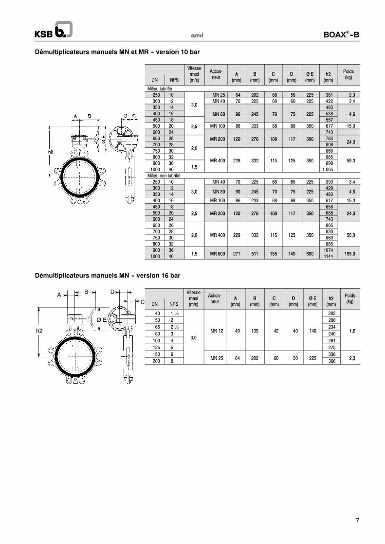
Démultiplicateurs manuels MN et MR -- version 10 bar
Vitessemaxi
Action-A B C D Ø E h2
Poids
DN NPSmaxi(m/s)
Actionneur
A(mm)
B(mm)
C(mm)
D(mm)
Ø E(mm)
h2(mm)
Poids(kg)
Milieu lubrifié250 10 MN 25 64 202 60 50 225 361 2,3300 12
3 0MN 40 70 225 60 60 225 422 3,4
350 143,0
483400 16 MN 80 90 245 70 75 225 538 4,6450 18
MN 80 90 245 70 75 225557
4,6
500 20 2,5 MR 100 86 233 88 88 350 677 15,0600 24
2,5743
650 26 MR 200 120 270 108 117 350 78324 0
700 282 0
MR 200 120 270 108 117 350808
24,0
h2 750 302,0
860h2800 32
MR 400 229 332 115 125 350885
58 0900 36
1 5MR 400 229 332 115 125 350
89858,0
1000 401,5
1 005Milieu non lubrifié
250 10 MN 40 70 225 60 60 225 393 3,4300 12
3 0 MN 80 90 245 70 75 225429
4 6350 14
3,0 MN 80 90 245 70 75 225483
4,6
400 16 MR 100 86 233 88 88 350 617 15,0450 18 658500 20 2,5 MR 200 120 270 108 117 350 688 24,0600 24
2,5 MR 200 120 270 108 117 350743
24,0
650 26 805700 28
2 0 MR 400 229 332 115 125 350830
58 0750 30
2,0 MR 400 229 332 115 125 350860
58,0
800 32 885900 36
1 5 MR 600 271 511 155 140 6001074
105 01000 40
1,5 MR 600 271 511 155 140 6001144
105,0
Démultiplicateurs manuels MN -- version 16 bar
AB D Vitesse
maxiAction-
A B C D Ø E h2Poids
C DN NPSmaxi(m/s)
Actionneur
A(mm)
B(mm)
C(mm)
D(mm)
Ø E(mm)
h2(mm)
Poids(kg)
40 1½ 203
Ø E 50 2 208
h2
Ø E65 2½
MN 12 49 135 42 40 140234
1 6h280 3
3 0
MN 12 49 135 42 40 140240
1,6
100 43,0
261
125 5 275
150 6MN 25 64 202 60 50 225
3382 3
200 8MN 25 64 202 60 50 225
3662,3

BOAX!--B
8
Variantes standard
Actionneur électrique ACTELEC Actionneur pneumatique ACTAIR / DYNACTAIR
PositionneurAMTRONIC / SMARTRONIC
Contact de fin de courseAMTROBOX

BOAX!--B
9
RaccordementsLes robinets BOAX!--B peuvent être montés entre les raccordements ci dessous (Autres types de raccordement sur demande).
-- EN 1092 PN 10 et 16-- ASME B16-1 cl.125 et B16-5 cl. 150
Corps à oreilles de démontage -- Type 2
Raccordement
DN NPSEN 1092 ASME
DN NPSPN 10 PN 16 B16.1 cl. 125 B 16.5 cl. 150
40 1½ $ $ $ $
50 2 $ $ $ $
65 2½ $ $ $ $
80 3 $ $ $ $
100 4 $ $ $ $
125 5 $ $ $ $
150 6 $ $ $ $
200 8 $! $ $! $!
250 10 $! $ $ $
300 12 $ $ $ $
350 14 $ $ $ $
400 16 $ $ $ $
450 18 $ $ $ $
500 20 $ $ $ $
600 24 $ $ $ $
$ Montage possible Intercaler une rondelle entre l’écrou et la nervuredu robinet
!
Corps à bossages taraudés à faces décalées -- Type 4
Raccordement
DN NPSEN 1092 ASME
DN NPSPN 10 PN 16 B16.1 cl. 125 B 16.5 cl. 150
40 1½ $ $ $ $
50 2 $ $ $ $
65 2½ $ $ $ $
80 3 $ $ $ $
100 4 $ $ $ $
125 5 $ $ $ $
150 6 $ $ $ $
200 8 $ $ $ $
250 10 $ $ $ $
300 12 $ $ $ $
350 14 $ $ $ $
400 16 $ $ $ $
450 18 $ $ $ $
500 20 $ $ $ $
550 22
600 24 $ $ $ $
$ Montage possible Raccordement non défini par la norme

BOAX!--B
10
Corps à brides à faces planes -- Type 5
Raccordement
DN NPSEN 1092 ASME
DN NPSPN 10 PN 16 B16.1 cl. 125 B 16.5 cl. 150
150 6 $ $ $ $
200 8 $ $ $ $
250 10 $ $ $ $
300 12 $ $ $ $
350 14 $ $ $ $
400 16 $ $ $ $
450 18 $ $ $ $
500 20 $ $ $ $
600 24 $ $ $ $
650 24
700 28 $" $"
750 30 $"
800 32 $" $"
900 36 $" $" $"
1000 40 $" $"
$ Montage possible
Raccordement non défini par la norme
Montage à brides autorisé"
Montage bout de ligne et démontage aval
Les robinets BOAX!--B Types 2, 4 et 5 se montent entre brides, par tirants, sans joints de bride.
Ils sont bi--directionnels et peuvent être installés dans n’importe quelle position.Le montage en bout de ligne et démontage aval à température ambiante des robinets de fabrication standard est limité aux DN et à lapression différentielle (#PS) suivant le tableau ci--dessous :
Gaz ou liquides* Liquides*
dangereux** non dangereux** dangereux** non dangereux**
Tous DN : non autoriséDN$ 200 : #PS = 10 bar max.
DN 250 à 1000#PS = 7 bar max.
DN$ 200 : #PS = 10 bar max.DN 250 à 1000#PS = 7 bar max.
DN$ 200 : #PS = 10 bar max.DN 250 à 1000#PS = 7 bar max.
* Sont considérés comme liquides, les fluides dont la pression de vapeur à la température maximale admissible est inférieure ouégale à 0,5 bar au dessus de la pression atmosphérique normale (1013 mbar).
** Fluide dangereux et non dangereux selon la classification de la DESP.NOTA :Un robinet installé au bout d’une tuyauterie avec une contre bride pleine à l’aval n’est pas à considérer comme montage bout deligne.
Démontage aval Montage en bout de ligne
Phase de démontage aval :En opérant successivementsur chacun des tirantsdiamétralement opposés.
BOAX!--B
11
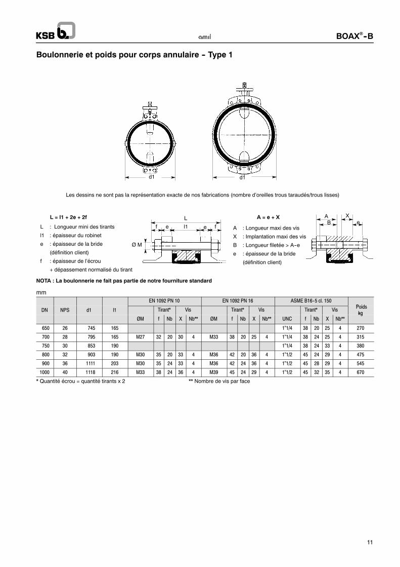
Boulonnerie et poids pour corps annulaire -- Type 1
L : Longueur mini des tirants
l1 : épaisseur du robinet
e : épaisseur de la bride
(définition client)
f : épaisseur de l’écrou
+ dépassement normalisé du tirant
A : Longueur maxi des vis
X : Implantation maxi des vis
B : Longueur filetée > A--e
e : épaisseur de la bride
(définition client)
AB e
d1
L = l1 + 2e + 2f
Les dessins ne sont pas la représentation exacte de nos fabrications (nombre d’oreilles trous taraudés/trous lisses)
f l1e e f
L
Ø M
XA = e + X
d1
NOTA : La boulonnerie ne fait pas partie de notre fourniture standard
mm
EN 1092 PN 10 EN 1092 PN 16 ASME B16--5 cl. 150Poids
DN NPS d1 l1 Tirant* Vis Tirant* Vis Tirant* VisPoidskg
ØM f Nb X Nb** ØM f Nb X Nb** UNC f Nb X Nb**kg
650 26 745 165 1”1/4 38 20 25 4 270
700 28 795 165 M27 32 20 30 4 M33 38 20 25 4 1”1/4 38 24 25 4 315
750 30 853 190 1”1/4 38 24 33 4 380
800 32 903 190 M30 35 20 33 4 M36 42 20 36 4 1”1/2 45 24 29 4 475
900 36 1111 203 M30 35 24 33 4 M36 42 24 36 4 1”1/2 45 28 29 4 545
1000 40 1118 216 M33 38 24 36 4 M39 45 24 29 4 1”1/2 45 32 35 4 670
* Quantité écrou = quantité tirants x 2 ** Nombre de vis par face

BOAX!--B
12
d1d1 d1
Les dessins ne sont pas la représentation exacte de nos fabrications (nombre d’oreilles trous taraudés/trous lisses)
Boulonnerie et poids pour corps à oreilles de démontage -- Type 2
NOTA : La boulonnerie ne fait pas partie de notre fourniture standard
L : Longueur mini des tirants
l1 : Largeur du robinet
e : Epaisseur de la bride
(définition client)
f : Epaisseur de l’écrou
+ dépassement normalisé du tirant
A : Longueur maxi des vis
X : Implantation maxi des vis
B : Longueur filetée > A--e
e : Epaisseur de la bride
(définition client)
AB e
L = l1 + 2e + 2f
f l1e e f
L
Ø M
XA = e + X
mm
EN 1092 PN 10 EN 1092 PN 16 ASME B16--5 cl. 150Poids
DN NPS d1 l1 Tirant * Vis Tirant* Vis Tirant* VisPoids
kgØM f Nb X Nb** ØM f Nb X Nb** UNC f Nb X Nb**
kg
40 1 ½ 108 33 M16 20 4 M16 20 4 1/2” 17 4 1,1
50 2 118 43 M16 20 4 M16 20 4 5/8” 20 4 1,3
65 2 ½ 132 46 M16 20 4 M16 20 4 5/8” 20 4 1,9
80 3 138 46 M16 20 8 M16 20 8 5/8” 20 4 2,5
100 4 150 52 M16 20 8 M16 20 8 5/8” 20 8 3,9
125 5 234 56 M16 20 8 M16 20 8 3/4” 24 8 4,7
150 6 260 56 M20 24 8 M20 24 8 3/4” 24 8 6,9
200 8 322 60 M20 24 8 M20 24 12 3/4” 24 8 10,5
250 10 394 68 M20 24 12 M24 29 12 7/8” 29 12 16,4
300 12 462 78 M20 24 12 M24 29 12 7/8” 29 12 30,0
350 14 538 78 M20 24 10 20 6 M24 29 10 24 6 1” 32 6 27 6 60,0
400 16 604 102 M24 29 10 24 6 M27 32 10 27 6 1” 32 10 27 6 80,0
450 18 656 114 M24 29 14 24 6 M27 32 14 27 6 1”1/8 35 10 30 6 110,0
500 20 716 127 M24 29 12 24 8 M30 35 12 30 8 1”1/8 35 12 30 8 145,0
600 24 836 154 M27 32 10 27 10 M33 38 10 33 10 1”1/4 38 10 32 10 220,0
* Quantité écrou = quantité tirants x 2 ** Nombre de vis par face

BOAX!--B
13
Boulonnerie et poids pour corps à bossages taraudées à faces surélevées type 4
Les dessins ne sont pas la représentation exacte de nos fabrications (nombre d’oreilles)
d1d1
AB e
XA = e + X
l1
A : Longueur maxi des vis
X : Implantation maxi des vis
B : Longueur filetée > A--e
e : Epaisseur de la bride
(définition client)
NOTA : La boulonnerie ne fait pas partie de notre fourniture standard
mmEN 1092 PN 10 EN 1092 PN 16 ASME B16--5 cl. 150
PoidsDN NPS d1 l1 Tirant* Vis Tirant* Vis Tirant * Vis
Poidskg
ØM f Nb X Nb** ØM f Nb X Nb** UNC f Nb X Nb**kg
40 1 ½ 108 33 M16 14 4 M16 14 4 1/2” 14 4 2,0
50 2 120 43 M16 18 4 M16 18 4 5/8” 18 4 2,5
65 2 ½ 134 46 M16 20 4 M16 20 4 5/8” 20 4 3,0
80 (1) 3 140 46 5/8” 20 4 4,0
80 (2) 3 178 46 M16 20 8 M16 20 8 4,5
100 4 210 52 M16 22 8 M16 22 8 5/8” 22 8 5,5
125 5 236 56 M16 22 8 M16 22 8 3/4” 23 8 9,0
150 6 260 56 M20 26 8 M20 26 8 3/4” 26 8 11,0
200 (3) 8 312 60 M20 26 8 3/4” 26 8 24,0
200 (4) 8 322 60 M20 26 12 25,0
250 10 396 68 M20 26 12 M24 29 12 7/8” 28 12 39,0
300 12 466 78 M20 26 12 M24 30 12 7/8” 28 12 46,0
350 (1) 14 510 78 1” 30 12 62,0
350 (2) 14 530 78 M20 26 16 M24 30 16 70,0
400 16 598 102 M24 31 16 M27 34 16 1” 34 16 101,0
450 (1) 18 622 114 1”1/8 37 16 122,0
450 (2) 18 654 114 M24 31 20 M27 34 20 139,0
500 20 708 127 M24 31 20 M30 37 20 1”1/8 37 20 179,0
600 24 822 154 M27 36 20 M33 42 20 1”1/4 42 20 256,0
* Quantité écrou = quantité tirants x 2 ** Nombre de vis par face
(1) Montage entre brides ASME B16--5 cl. 150.(2) Montage entre brides EN 1092 PN 10, PN 16.(3) Montage entre brides EN 1092 PN 10, ASME B16--5 cl. 150.(4) Montage entre brides EN 1092 PN 16.

BOAX!--B
14
Boulonnerie et poids pour corps à brides à faces planes -- Type 5
DN 150 à 600
Montage à bride non autorisé
L
fel1ef
ØM
Les dessins ne sont pas la représentation exacte de nos fabrications (nombre de trous taraudés/lisses).
d1
d1
L = l1 + 2e + 2f
Montage entre brides -- DN 200 à 600
A = e + X
A
x e
B
L : Longueur mini des tirants
l1 : épaisseur du robinet
e : épaisseur de la bride
(définition client)
f : Epaisseur de l’écrou
+ dépassement normalisé du tirant
A : Longueur maxi des vis
X : Implantation maxi des vis
B : Longueur filetée > A--e
e : épaisseur de la bride
(définition client)
NOTA : La boulonnerie ne fait pas partie de notre fourniture standard
mm
DN NPS ød1 l1
EN 1092 PN 10 EN 1092 PN 16ASME B16--1 cl. 125ASME B16--5 cl. 150 Poids
DN NPS ød1 l1Tirant* Vis Tirant* Vis Tirant* Vis
Poids
kg
ØM f Nb X Nb** ØM f Nb X Nb** UNC f Nb X Nb**
g
150 6 298 56 M20 24 4 20 4 M20 24 4 16 4 3/4” 24 4 20 4 11
200 8 343 60 M20 24 4 20 4 M20 24 8 16 4 3/4” 24 4 20 4 23
250 10 406 68 M20 24 8 20 4 M24 29 8 24 4 7/8” 29 8 24 4 40
300 12 483 78 M20 24 6 20 6 M24 29 6 24 6 7/8“ 29 6 24 6 60
350 14 533 78 M20 24 10 20 6 M24 29 10 24 6 1” 32 6 27 6 80
400 16 597 102 M24 29 10 24 6 M27 32 10 27 6 1” 32 10 27 6 105
450 18 640 114 M24 29 14 24 6 M27 32 14 27 6 1”1/8 35 10 30 6 130
500 20 715 127 M24 29 12 24 8 M30 35 12 30 8 1”1/8 35 12 30 8 180
600 24 840 154 M27 32 10 27 10 M33 38 10 33 10 1”1/4 38 10 32 10 260
* Quantité écrou = quantité tirants x 2 ** Nombre de vis par face

BOAX!--B
15
Boulonnerie et poids pour corps à brides à faces planes -- Type 5
DN 650 à 1000
Montage à bride autorisé pour une pression maximale différentielle de 10 bar
A
x e
B
L
fel1ef
ØM
Les dessins ne sont pas la représentation exacte de nos
fabrications (nombre de trous taraudés/lisses).
d1
d1
L = l1 + 2e + 2f
Montage entre brides -- DN 650 à 1000
Montage à brides -- DN 650 à 1000
A = e + X
A
x e
B
Définition de la boulonnerie : Nous consulter.
C
C
L : Longueur mini des tirants
l1 : Largeur du robinet
e : Epaisseur de la bride
(définition client)
f : Epaisseur de l’écrou
+ dépassement normalisé du tirant
A : Longueur maxi des vis
X : Implantation maxi des vis
B : Longueur filetée > A--e
e : Epaisseur de la bride
(définition client)
NOTA : La boulonnerie ne fait pas partie de notre fourniture standard
mm
DN NPS ød1 l1 C
EN 1092 PN 10 EN 1092 PN 16ASME B16--1 cl. 125ASME B16--5 cl. 150 Poids
DN NPS ød1 l1 CTirant* Vis Tirant* Vis Tirant* Vis
Poids
kg
ØM f Nb X Nb** ØM f Nb X Nb** UNC f Nb X Nb**
g
650 26 869 (2) 165 31,0 1”1/4 38 20 25 4 305
700 28 895 (1) 165 32.5 M27 32 20 27 4 330
700 28 925 (2) 165 32.5 M33 38 20 25 4 1”1/4 38 24 25 4 350
750 30 985 (2) 190 33.5 1”1/4 38 24 33 4 350
800 32 1 015 (1) 190 35,0 M30 35 20 30 4 505
800 32 1 075 (2) 190 35,0 M36 42 20 36 4 1”1/2 45 24 29 4 525
900 36 1 115 (1) 203 37.5 M30 35 24 30 4 590
900 36 1 160 (2) 203 37.5 M36 42 24 36 4 1”1/2 45 28 29 4 620
1000 40 1 230 (1) 216 40,0 M33 38 24 33 4 740
1000 40 1 275 (2) 216 40,0 M39 45 24 29 4 1”1/2 45 32 35 4 780
* Quantité écrou = quantité tirants x 2 ** Nombre de vis par face
(1) Montage entre brides EN 1092 PN 10.(2) Montage entre brides EN 1092 PN 16, ASME B 16--1 cl. 125.

BOAX!--B
16
Cotes de bridage
Les robinets BOAX!--B sont conçus pour être installés sans joint de bride entre tous les types de brides et tous les raccordementscouramment utilisés. La manchette élastomère assure directement l’étanchéité aux brides. Il est indispensable de vérifier lacompatibilité du raccordement avec les limites définies dans le tableau ci-dessous.Les cotes de bridage indiquées dans le tableau ci-dessous sont valables pour tous les Types de corps.
ø2a ø2bø1ø3
ø5
ø4 ø610
20
! ø2a et ø3 : diamètre sur la face d’appui de la bride.! ø2b : diamètre extérieur de l’embout à souder du collet avec contre bride tournante suivant normes DIN 2642 et NFE 29--251.
mm
DN NPS
øoptimal
ø maxi toléréø mini toléré
sur la face dela bride
ø mini à 10 mmde la face de la
bride
ø mini à 20 mmde la face de la
bride
ø mini toléré del’épaulementdes brides à
face surélevée
ø1 ø2a ø2b ø3 ø4 ø5 ø6
40 1 ½ 40 54,0 49 32 ------ ------ 77
50 2 49 63,0 61 33 ------ ------ 86
65 2 ½ 65 80,0 77 55 13 ------ 107
80 3 77 93,0 89 71 50 ------ 121
100 4 96 116,0 115 90 74 40 141
125 5 123 141,5 140 119 107 87 171
150 6 146 170,5 * 169 144 134 120 196
200 8 196 222,0 * 220 196 189 178 250
250 10 249 276,5 * 273 249 243 234 306
300 12 298 327,5 * 324 297 291 283 358
350 14 330 361,0 356 326 321 314 399
400 16 380 412,0 407 370 366 358 452
450 18 430 463,0 457 422 416 409 505
500 20 480 515,0 508 470 464 457 558
600 24 580 617,0 610 566 560 554 664
650 26 630 668,0 620 614 608 723
700 28 680 718,0 671 666 660 773
750 30 680 718,0 671 666 660 773
800 32 780 820,0 769 764 758 880
900 36 880 924,0 869 864 859 987
1000 40 980 1 027,0 970 965 960 1 094
* Vérifier que le corps est bien centré entre les tirants
NOTA :Le montage direct sur bride revêtuecaoutchouc et avec joint de dilation n’estpas autorisé.Nous consulter.
Joint de dilatationBride revêtue caoutchouc

BOAX!--B
17
Notes

BOAX!--B
18
Notes

BOAX!--B
19
Notes

KSB S.A.S
4, allée des Barbanniers ! 92635 Gennevilliers Cedex (France)
Tel. : +33 1 41 47 75 00 ! Fax : +33 1 41 47 75 10 ! www.ksb.fr
BOAX!--B
Les avantages en un seul coup d’œil
!
!!
!
!
!
!
!
!
!
!
Manchette AMRING ! agréée eau potable-- ACS (accréditation de conformité sanitaire)
conformément à la législation française-- WRAS conformément à la norme BS 6920
(agrément Water Council -- Royaume Uni)-- DVGW conformément à la législation
allemande KTW
Repère indiquant la position de
l’obturateur
Embase conforme à la norme
ISO 5211
Etanchéité externe interne
conservée lorsque l’actionneurest retiré
Coussinet en PTFE
chargé sur support acier
Etanchéité aux passages
d’arbres réalisée sur lesportées sphériques par
surcompression
volumique de la manchette
Etanchéité Amont / Aval
Obturateur usiné sphériqueassurant une parfaite
étanchéité Amont / Aval
Entrainement Arbre/Obturateur
par cannelures ou clavettes :pas de contact avec le fluide
véhiculés
Etanchéité aux brides
Forme spécialement étudiéepour obtenir par compression
une étanchéité totale aux brides
Face à face
conforme aux normes ISO5752 série 20 et EN 558 série 20
Vis anti--éjection
de l’arbre
Vis anti--éjection
de l’arbre
03
.12
.07
Do
cu
me
nt
no
nc
on
tra
ctu
el.
So
us
rés
erv
ed
em
od
ific
ati
on
ste
ch
niq
ue
s.
84
09
.11
/5--
20