types of structures and loadsweb.itu.edu.tr/~ustunda1/course/slides_19.09.2013.pdf · types of...
TRANSCRIPT

Types of Structures and Loads
THEORY OF STRUCTURES
Asst. Prof. Dr. Cenk Üstündağ

Asst. Prof. Dr. Cenk UstundagE-mail: [email protected] Nr: 103Web: http://web.itu.edu.tr/ustunda1

Course Content
Introduction Analysis of Statically Determinate Structures
Simple Beams and Frames, Cantilever Beams, ContinuousBeams with Hinges, Three-Hinged Archs and Frames, RoofTrusses,
Deflections,
Analysis of Statically Indeterminate Structures Force Method Moment Distribution (Cross) Method

Introduction
A structure refers to a system of connected parts used to support a load. Important examples related to civil engineering include
buildings, bridges and towers;
and in other branches of engineering, ship and aircraft frames, tanks, pressure vessels, mechanical systems, and electrical supporting structures
Such structures are composed of one or more solid elements arranged so that the whole structures as well as their components are capable of holding themselves without appreciable geometric change during loading and unloading.

The design of a structure involves many considerations,among which are four major objectives that must besatisfied: The structure must meet the performance requirement (utility). The structure must carry loads safely (safety). The structure should be economical in material, construction,
and cost (economy). The structure should have a good appearance (aesthetics).
Introduction

Introduction
Consider, for example, the roof truss resting on columnsshown below.

Introduction
The purposes of the roof truss and of the columns are, on the one hand, to hold in equilibrium their own weights, the load of roof covering and the wind and snow.
Also to provide rooms for housing a family, for a manufacturing plant, or for other uses.
During its development the design is generally optimizedto achieve minimum expenditure for materials andconstruction uses.

Introduction
The complete design of a structure is outlined in thefollowing stages: Developing a general layout Investigating the loads Stress analysis Selection of elements Drawing and detailing
These five stages are interrelated and may be subdivided and modified
In many cases they must be carried out more or less simultaneously
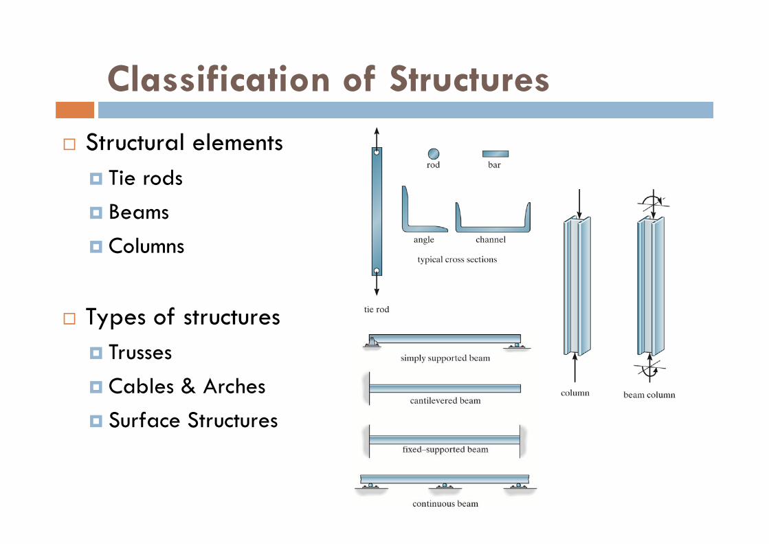
Classification of Structures
Structural elements Tie rods Beams Columns
Types of structures Trusses Cables & Arches Surface Structures
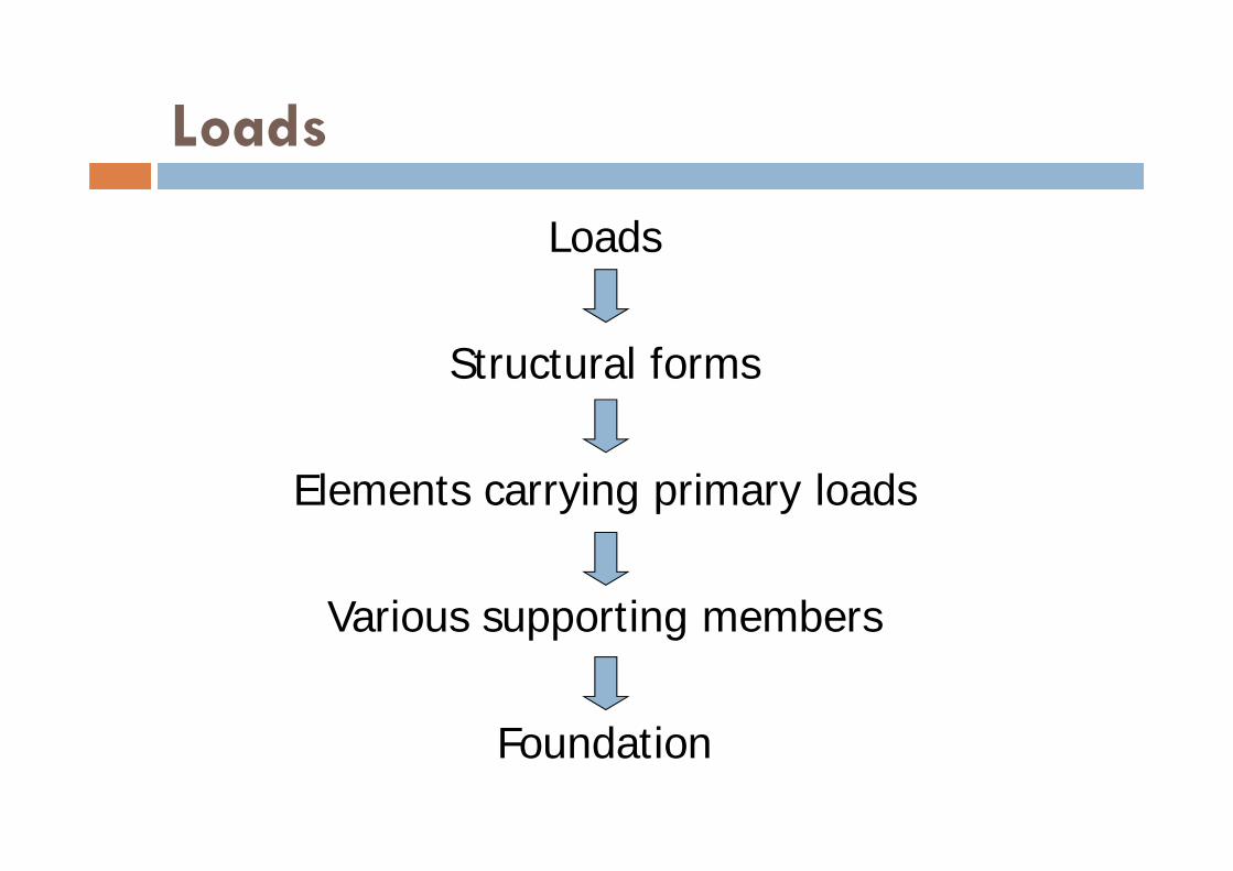
Loads
Loads
Structural forms
Elements carrying primary loads
Various supporting members
Foundation

Loads
Design loading for a structure is often specified in codes General building codes Design codes

Loads
Types of load Dead loadsWeights of various structural membersWeights of any objects that are attached to the structure

Loads Live loads Varies in magnitude & location Building loads
Depends on the purpose for which the building is designed These loadings are generally tabulated in local, state or national code Uniform, concentrated loads
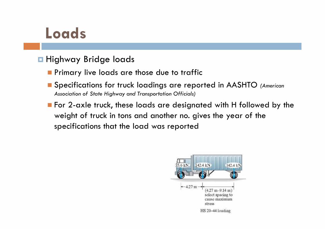
Loads Highway Bridge loads Primary live loads are those due to traffic Specifications for truck loadings are reported in AASHTO (American
Association of State Highway and Transportation Officials)
For 2-axle truck, these loads are designated with H followed by the weight of truck in tons and another no. gives the year of the specifications that the load was reported

Loads Railway Bridge loads Loadings are specified in AREA A modern train having a 320kN (72k) loading on the driving axle of
the engine is designated as an E-72 loading

Loads Impact loads Due to moving vehicles The % increase of the live loads due to impact is called the impact
factor, I
load live the tosubjected is that min span theoflength
3.01.38
24.15
LL
I

Loads
Wind loads Kinetic energy of the wind is converted into potential energy of
pressure when structures block the flow of wind Effects of wind depends on density & flow of air, angle of incidence,
shape & stiffness of the structure & roughness of surface For design, wind loadings can be treated as static or dynamic
approach
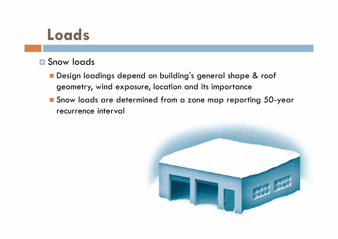
Loads Snow loads Design loadings depend on building’s general shape & roof
geometry, wind exposure, location and its importance Snow loads are determined from a zone map reporting 50-year
recurrence interval
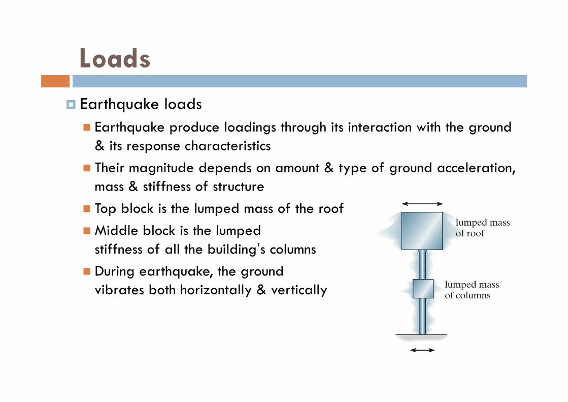
Loads Earthquake loads Earthquake produce loadings through its interaction with the ground
& its response characteristics Their magnitude depends on amount & type of ground acceleration,
mass & stiffness of structure Top block is the lumped mass of the roofMiddle block is the lumped
stiffness of all the building’s columns During earthquake, the ground
vibrates both horizontally & vertically
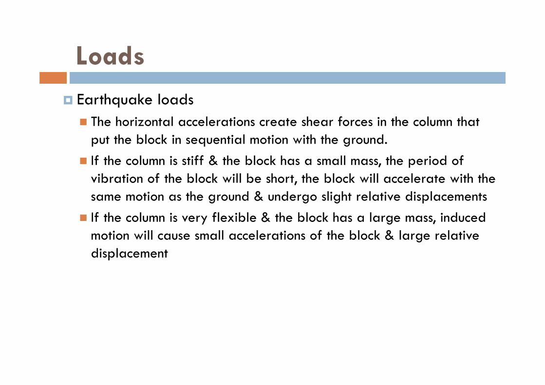
Loads Earthquake loads The horizontal accelerations create shear forces in the column that
put the block in sequential motion with the ground. If the column is stiff & the block has a small mass, the period of
vibration of the block will be short, the block will accelerate with the same motion as the ground & undergo slight relative displacements
If the column is very flexible & the block has a large mass, induced motion will cause small accelerations of the block & large relative displacement
Loads Hydrostatic & Soil Pressure The pressure developed by these loadings when the structures are
used to retain water or soil or granular materials E.g. tanks, dams, ships, bulkheads & retaining walls
Other natural loads Effect of blast Temperature changes Differential settlement of foundation
Structural Design
Material uncertainties occur due tovariability in material propertiesresidual stress in materials intended measurements being different from fabricated sizesmaterial corrosion or decay
Many types of loads can occur simultaneously on a structure

Structural Design Allowable-stress design (ASD) methods include both the
material and load uncertainties into a single factor of safety. The many types of loads discussed previously can occur simultaneously on a structure, but it is very unlikely that the maximum of all these loads will occur at the same time. For example, both maximum wind and earthquake loads normally do not act simultaneously on a structure.
For allowable-stress design the computed elastic stress in the material must not exceed the allowable stress for each of various load combinations. Load combinations specified by the ASCE 7-02 StandardDead load0.6 (dead load) + wind load0.6 (dead load) + 0.7(earthquake load)

Structural Design
Ultimate strength design is based on designing the ultimate strength of critical sections
This method uses load factors to the loads or combination of loads1.4 (Dead load)1.2 (dead load) + 1.6 (live load) + 0.5 (snow load)1.2 (dead load) + 1.5(earthquake load) + 0.5 (live load)
Analysis of Statically Determinate Structures

Idealized Structure An exact analysis of a structure can never be carried out,
since estimates always have to be made of the loadings and the strength of the materials composing the structure.
It is important to develop the ability to model or idealize a structure so that the structural engineer can perform a practical force analysis of the members
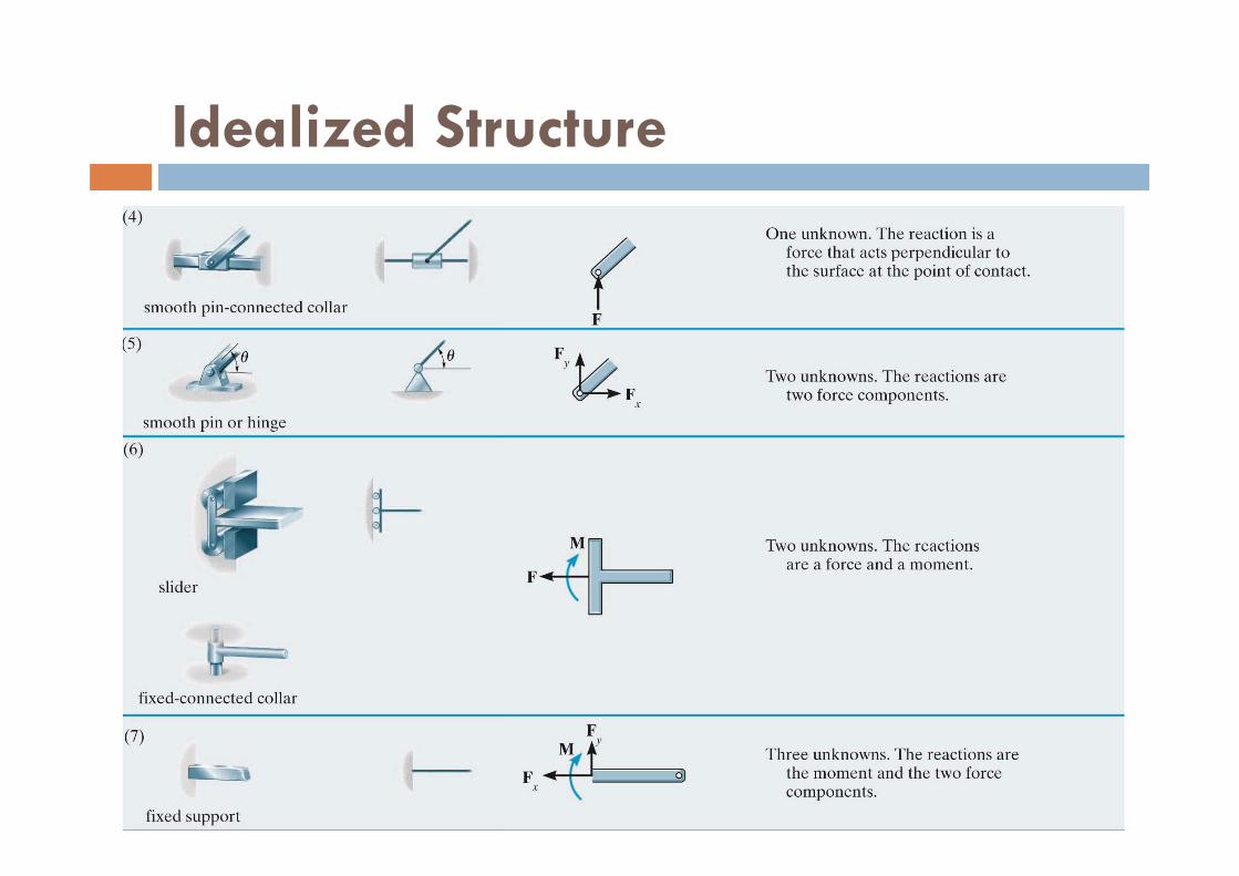
Support Connections: Structural members are joined together in various ways depending on the intent of the designer. The three types of joints most often specified are Pin connection (allows some freedom for slight rotation) Roller support (allows some freedom for slight rotation) Fixed joint (allows no relative rotation)

Idealized Structure

Idealized Structure
Idealized models used in structural analysis that represent varioussupport types.

Idealized Structure
Support Connections In reality, all connections exhibit some stiffness toward joint
rotations owing to friction & material behavior If k = 0 the joint is pin and -> , the joint is fixed When selecting the model for each support, the engineer must
be aware how the assumptions will affect the actual performance
The analysis of the loadings should give results that closely approximate the actual loadings

Idealized Structure
Support Connections In reality, all supports actually exert distributed surface loads
on their contacting members The concentrated forces and moments shown in Table 2–1 represent the resultants of these load distributions.
This representation is, of course, an idealization; however, it is used here since the surface area over which the distributed load acts is considerably smaller than the total surface area of the connecting members.

Idealized Structure
Idealized Structure

Idealized Structure
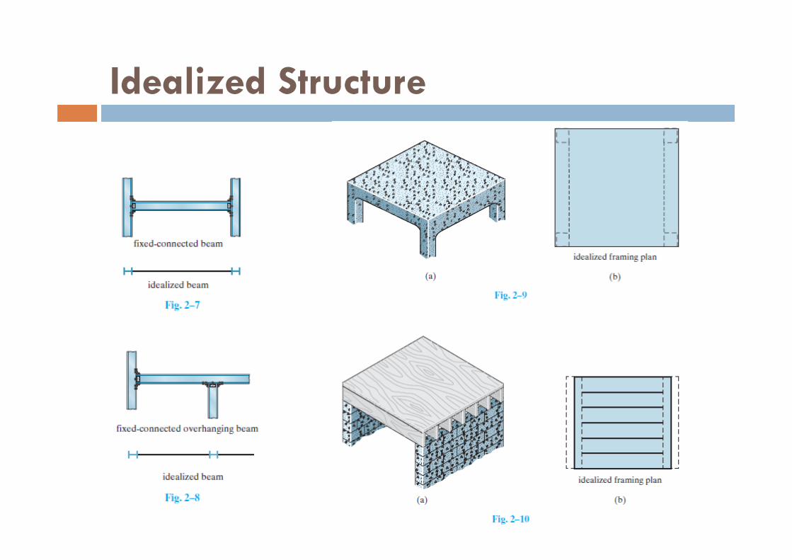
Idealized Structure Consider the jib crane & trolley, we neglect the thickness of the
2 main member & will assume that the joint at B is fabricated to be rigid
The support at A can be modeled as a fixed support

Idealized Structure
Idealized Structure Consider the framing used to support a typical
floor slab in a building The slab is supported by floor joists located at even intervals These are in turn supported by 2 side girders AB & CD

Idealized Structure
Idealized Structure For analysis, it is reasonable to assume that the joints are pin
and/or roller connected to girders & the girders are pin and/or roller connected to columns
Idealized Structure

Idealized Structure
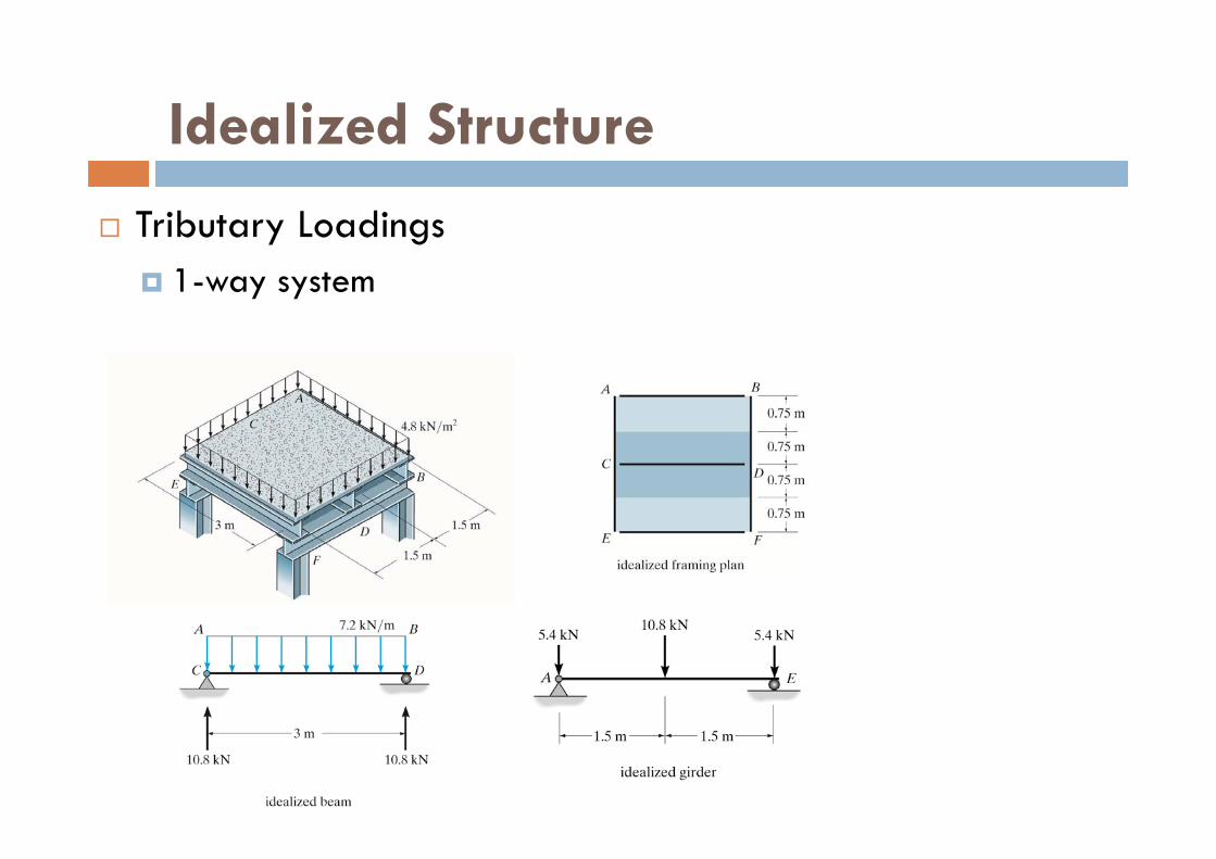
Tributary Loadings There are 2 ways in which the load on surfaces can transmit to
various structural elements 1-way system 2-way system
Idealized Structure
Tributary Loadings 1-way system

Idealized Structure
Tributary Loadings 2-way system

Example
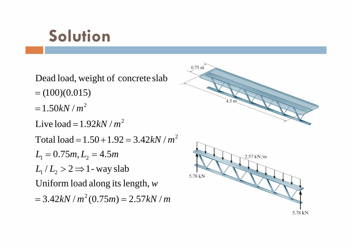
The floor of a classroom is supported by the bar joists. Each joist is 4.5m long and they are spaced 0.75m on centers. The floor is made from lightweight concrete that is 100mm thick. Neglect the weight of joists & the corrugated metal deck, determine the load that acts along each joist.
Solution
mkNmmkNw
LLmLmL
mkNmkN
mkN
/57.2)75.0(/42.3 length, its along load Uniform
slabway -12/5.4,75.0
/42.392.150.1 load Total/92.1 load Live
/50.1)015.0)(100(
slab concrete of weight load, Dead
2
21
21
2
2
2

Principle of Superposition
The principle of superposition forms the basis for much of the theory of structural analysis. It may be stated as follows: The total displacement or internal loadings (stress) at a point in
a structure subjected to several external loadings can be determined by adding together the displacements or internal loadings (stress) caused by each of the external loads actingseparately.
For this statement to be valid it is necessary that a linearrelationship exist among the loads, stresses, and displacements.

Principle of Superposition
2 requirements for the principle to apply: The material must behave in a linear-elastic manner, so that
Hooke’s law is valid, and therefore the load will be proportional to displacement.
The geometry of the structure must not undergo significant change when the loads are applied, i.e., small displacement theory applies. Large displacements will significantly change the position and orientation of the loads.
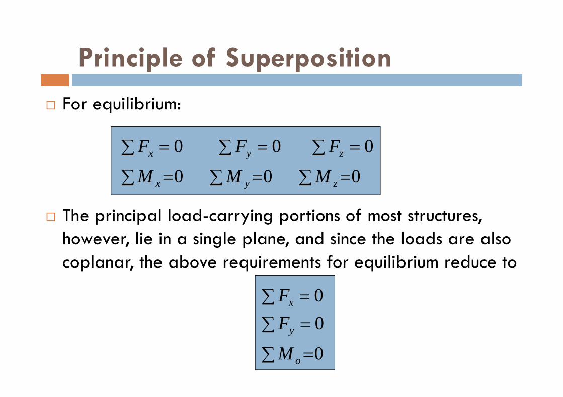
Principle of Superposition
For equilibrium:
The principal load-carrying portions of most structures, however, lie in a single plane, and since the loads are also coplanar, the above requirements for equilibrium reduce to
0 0 0
0 0 0
zyx
zyx
MMM
FFF
0
00
o
y
x
M
FF

Determinacy Equilibrium equations provide both the necessary and sufficient
conditions for equilibrium All forces can be determined strictly from these equations No. of unknown forces > equilibrium equations => statically
indeterminate This can be determined using a free body diagram

Determinacy For a coplanar structure
r = number force and moment reaction componentsn = number of parts
The additional equations needed to solve for the unknown equations are referred to as compatibility equations
} ateindetermin statically ,3} edeterminat statically ,3
nrnr
Example
Classify each of the beams as statically determinate or statically indeterminate. If statically indeterminate, report the no. of degree of indeterminacy. The beams are subjected to external loadings that are assumed to be known & can act anywhere on the beams.

Solution
133,1,3 nr
135,1,5 nr
Statically determinate
Statically indeterminate to the second degree

Solution
236,2,6 nr
3310,3,10 nrStatically indeterminate to the first degree
Statically determinate
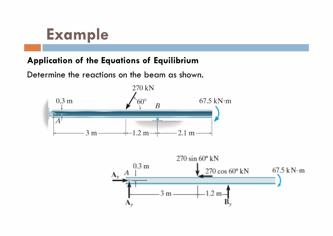
ExampleApplication of the Equations of Equilibrium
Determine the reactions on the beam as shown.

Solution
0
0 0
0
0 270 60 0135
0 270 60 3 270 60 0 3 4 2 67 5 0173 4
0 270 60 173 4 060 4
; coskN
With anti‐clockwise moments in the direction,
; sin ( ) cos ( . ) ( . ) .
. kN
; sin .
. kN
x x
x
A y
y
y y
y
F AA
M B
B
F A
A

ExampleThe compound beam shown is fixed at A. Determine the reactions at A, B, and C. Assume that the connection at B is a pin and C is a roller.

Solution

Solution
0 8 4 5 0 1 78
0 1 78 0 1 780 0
Segment :With anti‐clockwise moments in the direction,
; ( . ) . kN
; . . kN
;
c y y
y y y
x x
BC
M B B
F C C
F B
0 36 3 1 78 6 0 97 30 36 1 78 0 34 2
0 0
Segment :With anti‐clockwise moments in the direction,
; ( ) ( . )( ) . kN•m
; . . kN
;
A A A
y y y
x x
AB
M M M
F A A
F A