types of rafters - discount tools the online bargain tool source
TRANSCRIPT

The roof's main purpose is to keep out the rain, cold, or heat. It must be strong enough to with standhigh winds; sloped to shed water; and, in areas of heavy snow, it must be constructed more rigidlyto bear the extra weight. This chapter will familiarize carpenters with the most common types ofroof construction and materials. This chapter also covers reroofing.
ROOF FRAMING
Roofs for TOs are chosen to suit the building; the climate; the estimated length of time thebuilding will be used; and the material, time, and skill required for construction. TO constraintsdictate simple design as shown in Figure 7-1.

ROOFING TERMS
When framing a roof (Figure 7-2), carpenters must be familiarwith commonly used roofingterms (Figures 7-3 and 7-4).
RAFTERS
Rafters make up the mainframework of all roofs. They areinclined members spaced from16 to 48 inches apart. They varyin size, depending on length andspacing. The tops of inclinedrafters are fastened to the ridgeor another rafter, depending onthe type of roof. Rafters rest on the top wall plate.
Rafters are nailed to the plate, not framed into it. Some are cut to fit the plate, while in hastyconstruction they are merely laid on top of the plate and nailed in place. They may extend a shortdistance beyond the wall to form the eaves and protect the sides of the building.
Types of Rafters
Examples of most types of rafters are shown in Figure 7-3. The four types are
Common Rafters. These are framing members that extend at right angles from the plate line tothe roof ridge. They are called common rafters because they are common to all types of roofs andare used as the basis for laying out other types of rafters.
Hip Rafters. These are roof members that extend diagonally from the corner of the plate to theridge.

Valley Rafters. These rafters extend from the plate to the ridge along the lines wheretwo roofs intersect.
Jack Rafters. These are a common rafter. The three kinds of jack rafters are the
• Hip jack, which extends from the plate to the hip rafter.• Valley jack, which extends from the ridge of the valley rafter.• Cripple jack, which is placed between a hip rafter and a valley rafter. The cripple jack rafter is
also part of a common rafter, but it touches neither the ridge of the roof nor the rafter plate.

Collar Tie and Beam
A collar tie or beam (Figure 7-7) is a piece of stock (usually 1 x 4, 1 x 6, l x 8, or 2 x 4) fastened in ahorizontal position to a pair of rafters between the plate and the ridge of the roof. This type ofbeam keeps the building from spreading. Most codes and specifications require them to be 5 feetapart or every third rafter, whichever is less. Collar ties are nailed to common rafters with four 8dnails to each end of a 1-inch tie. If 2-inch material is used for the tie, they are nailed with three16d nails at each end. This type of bracing is used on small roofs where no ceiling joists are used
and the building is not wide enough to require a truss.
In small roofs that cover only narrow buildings in which the rafters are short, there is no need forinterior support or bracing. In long spans, the roof would sag in the middle if it were notstrengthened in some way. To support long rafters, braces or other types of supports must beinstalled.
Rafter Layout
Rafters must be laid out andcut with slope, length, andoverhang exactly right sothat they will fit when placedin the roof.
Scale or MeasurementMethod. The carpentershould first determine thelength of the rafter and thelength of the lumber fromwhich the rafter may be cut.If he is working from a roofplan, he learns the rafter lengths and the width of the building from the plan. If no plans areavailable, the width of the building must be measured.

Step 1. To determine the rafterlength, first find one-half of thehorizontal distance (total run)of the rafter. The amount ofrise per foot will not beconsidered yet. (For example, ifthe building is 20 feet wide,half of the span will be 10 feet.See the example below.)
Step 2. After the length hasbeen determined, lay thetimber on sawhorses (sawbenches), with the crown orbow (if it has any) as the topside of the rafter. If possible, select a straight piece for the pattern rafter. If a straight piece is notavailable, have the crown away from the person laying out the rafter.
Step 3. Hold the square with the tongue in your left hand, the blade in your right, and the heeltoward your body. Place the square as near the upper end of the rafter as possible. (For example,in Figure 7-8, page 7-6 (step 1) the figures 8 on the tongue and 12 on the blade are placed along thetimber edge that is to be the top edge of the rafter.)
Step 4. Mark along the outside tongue edge of the square, which will be the plumb cut at the ridge.
Step 5. Since the length of the rafter is known to be 12 feet and 1/6 inch, measure the distancefrom the top of the plumb cut and mark it on the timber. Hold the square in the same manner withthe 8 mark on the tongue directly over the 12-foot 1/6-inch mark. Mark along the tongue of thesquare to give the plumb cut for the seat (Figure 7-8, step 2).
Step 6. Measure off,perpendicular to this mark, thelength of overhang along thetimber. Make a plumb-cut markin the same way, keeping thesquare on the same edge of thetimber (Figure 7-8, step 3). Thiswill be the tail cut of the rafter.Often, the tail cut is made squareacross the timber.
Step 7. The level cut or width ofthe seat is the width of the platemeasured perpendicular to theplumb cut, as shown in Figure 7-8, step 4. Using a try square,square the lines down on thesides from all level and plumb-cut lines. Now the rafter is readyto be cut (Figure 7-8, step 5).

Step-Off Method. The rafter length of any building may be determined by "stepping it off bysuccessive steps with the square, as follows:
Step 1. Step off the same number of steps as there are feet in the run. For example, if a building is20 feet 8 inches wide, the run of the rafter would be 4 inches over 10 feet.
Step 2. This 4 inches is taken care of in the same manner as the full-foot run; that is, with thesquare at the last stepposition, make a mark on therafters at the 4-inch mark(Figure 7-9, step 1).
Step 3. With the square heldfor the same cut as before,make a mark along thetongue. This is the line lengthof the rafter. The seat cut andhangover are made asdescribed above and shown inFigure 7-9, steps 2, 3, and 4.
NOTE: When laying offrafters by any method, besure to recheck the workcareful1y. When tworafters have been cut, it is best to put them in place to see if they fit. Minor adjustmentsmay be made at this time without serious damage or waste of material.
Table Method. The framing square may have one or two types of rafter tables on the blade. Onetype gives both the line length of any pitch of rafter per foot of run and the line length of any hip orvalley rafter per foot of run. The difference in length of the jack rafter, spaced 16 or 24 inches (oncenter), is also shown in the table. Where the jack, hip, or valley rafter needs side cuts, the cut isgiven in the table. The other type of table gives the actual length of a rafter for a given pitch andspan.
Rafter Table, Type 1. Type 1 (Figure 7-10) appears on the face of the blade. This type is used todetermine the length of the common, valley, hip, and jack rafters and the angles at which they

must be cut to fit at the ridge and plate.
To use the table, the carpenter must first know what each figure represents.
• The row of figures in the first line represents the length of common rafters per foot of run, asthe title at the left-hand end of the blade indicates.
• Each set of figures under each inch division mark represents the length of rafter per foot ofrun, with a rise corresponding to the number of inches over the number. (For example, underthe 16-inch mark appears the number 20.00 inches. This number equals the length of a rafterwith a run of 12 inches and a rise of 16 inches. Under the 13-inch mark appears the number17.69 inches, which is the rafter length for a 12-inch run and a 13-inch rise.) See the Type 1layout example below.
NOTE: The other five lines of figures in the table will not be discussed, as they areseldom used in the TO.
The remaining procedure for laying out the rafters after the length has been determined is asdescribed previously.
Rafter Table, Type 2. Type 2 (Figure 7-11, page 7-8) appears on the back of the blade of somesquares. This shows the run, rise, and pitch of rafters of the seven most common pitches of roof.

The figures are based on the horizontal measurement of the building from the center to theoutside.
The rafter table and the outside edge of the back of the square, both the body and tongue, are intwelfths. (The inch marks may represent twelfths of an inch or twelfths of a foot.) This table isused in connection with the marks and figures on the outside edge of the square. At the left end ofthe table are figures representing the run, the rise, and the pitch:
• In the first column, the figures are all 12 (12 inches or 12 feet). They represent the runof 12.
• The second column of figures represents various rises.• The third column of figures (in fractions) represents the various pitches.
These three columns of figures show that a rafter with a run of 12 and a rise of 4 has a 1/6 pitch,12 and 6 has a 1/4 pitch, and 12 and 12 has a 1/2 pitch. For example, use this scale for—
• A roof with a 1/6 pitch (or the rise of 1/6 the width of the building) and a run of 12 feet. Find 1/6in the table, then follow the same line of figures to the right until directly beneath the figure12. Here appear the numbers 12, 7, 1O, which is the rafter length required and whichrepresents 12 feet 7 inches, and 10/12 of an inch. They are written as follows: 12 feet 7 10/12inches.
• A roof with a 1/2 pitch (or a rise of 1/2 the width of the building) and a run of 12 feet. The rafterlength is 16, 11, 6, or 16 feet 11 6/12 inches.
• A roof with a run of more than 23 feet. For example, if the run is 27 feet, find thelength for 23 feet, then find the length for 4 feet and add the two. The run for 23 feetwith a pitch of 1/4 is 25 feet 8 5/12 inches. For 4 feet, the run is 4 feet 5 8/12 inches.The total run for 27 feet is 30 feet 2 1/12 inches.
NOTE: When the run is in inches, the rafter table reads inches and twelfths instead offeet and inches.
See the Type 2 rafter table layout example at the top of the next page.
After the length of the rafter has been found, the rafter is laid out as explained previously.

TRUSSES
A truss is a framed or jointed structure composed of straight members connected only at theirintersections in such a way that if loads are applied at these intersections, the stress in eachmember is in the direction of its length. Straight, sound timber should be used in trusses. Thetypes of trusses used in building construction are shown in Figure 7-12. (The Howe and Finktrusses are most commonly used.) Truss terms are listed in Figure 7-13, page 7-10.
Trusses are used for large spans to give wide, unobstructed floor space for such large buildings asshops and hangars. Sometimes small buildings are trussed to save material. These small trussesact as rafters and give the roof rigidity.
The web members of a truss divide it into triangles. The members indicated by heavy linesnormally carry tensile stresses for vertical loads. Sometimes the top chords of these trussesslope slightly in one or two directions for roof drainage, but this does not change the type of truss.The necessary number of subdivisions, or panels, depends upon the length of the span and the typeof construction.
Truss Supports
Trusses are supported by bearing walls, posts, or other trusses. To brace a truss to a wall or post,knee braces are used as shown in Figure 7-14. These braces tend to make a truss of the entirebuilding by tying the wall to the roof.
Purlins
Purlins are used in roof construction to support corrugated sheet metal if it is used, or to supportthe sheathing of roofs framed with trusses.
• In small roofs, purlins are inserted between the rafters and nailed through the rafters.• In large buildings where heavy trusses are used, the purlins are continuous members that rest

on the trusses and support the sheathing.• In small buildings, such as barracks, mess halls, and small warehouses, 2 x 4s are used for
purling, with the narrow side up.
Truss Layout
To lay out a truss, use Figure 7-15 and the following steps:
Step 1. Get the material to a level spot of ground where work benches will be almost level.
Step 2. Obtain from the blueprints the measurement of all pieces to be used in the truss.
Step 3. Lay out the length on the different sizes of timber and cut them accurately.
Step 4. After all lengths are cut, lay them in their correct position to form a truss.
Step 5. Nail them together temporarily.
Step 6. Lay out the location of all holes to be bored. Recheck the measurements for accuracy.
Step 7. Bore holes to the size called for on the print. Use a brace and bit or the woodborer thataccompanies the air compressor. Bore holes perpendicular to the face of the timber.

Step 8. After the holes have been bored, dismantle the truss and withdraw the nails.
Truss Assembly
Assembling a truss after it has been cut and bored is simple (Figure 7-16). In most cases, timberconnectors are used where different members of the truss join. Straight, sound timber should beused in trusses.
• Assemble the truss withthe timber connectors inplace.
• Place the bolts in the holesand tighten them.
• Place washers at the headand nut ends of each bolt.
Rafters are usually made intotrusses, as shown in Figure 7-17. Two rafters are connectedat the top, using a collar tiewell nailed into both rafters.Before any ties or chords arenailed, the rafters should bespread at the lower end toequal the width of the
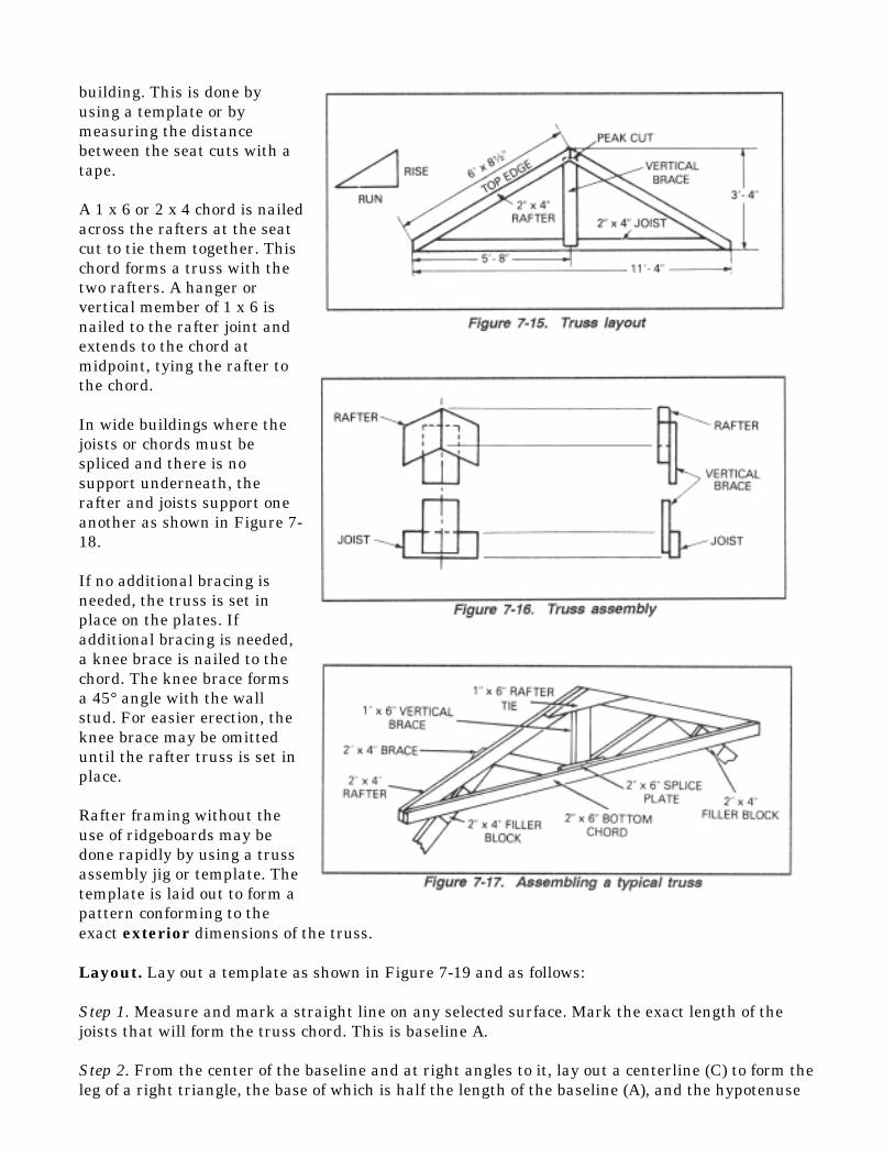
building. This is done byusing a template or bymeasuring the distancebetween the seat cuts with atape.
A 1 x 6 or 2 x 4 chord is nailedacross the rafters at the seatcut to tie them together. Thischord forms a truss with thetwo rafters. A hanger orvertical member of 1 x 6 isnailed to the rafter joint andextends to the chord atmidpoint, tying the rafter tothe chord.
In wide buildings where thejoists or chords must bespliced and there is nosupport underneath, therafter and joists support oneanother as shown in Figure 7-18.
If no additional bracing isneeded, the truss is set inplace on the plates. Ifadditional bracing is needed,a knee brace is nailed to thechord. The knee brace formsa 45° angle with the wallstud. For easier erection, theknee brace may be omitteduntil the rafter truss is set inplace.
Rafter framing without theuse of ridgeboards may bedone rapidly by using a trussassembly jig or template. Thetemplate is laid out to form apattern conforming to theexact exterior dimensions of the truss.
Layout. Lay out a template as shown in Figure 7-19 and as follows:
Step 1. Measure and mark a straight line on any selected surface. Mark the exact length of thejoists that will form the truss chord. This is baseline A.
Step 2. From the center of the baseline and at right angles to it, lay out a centerline (C) to form theleg of a right triangle, the base of which is half the length of the baseline (A), and the hypotenuse

of which (B) is the length of the rafter measured as indicated.
Step 3. Nail 2 x 4 x 8 blocks flush with the ends of baseline A and centerline C as shown in Figure7-19. Mark the centerline on the center jig blocks.
Assembly. Assemble with a template as shown in Figure 7-19 and as follows:
Step 1. Start the assembly by setting a rafter in the jig with the plate cut fitted over the jig blockat one end of the baseline. The peak is flush with the centerline on the peak jig block. Nail aholding block outside the rafter at point D.
Step 2. Lay one 2 x 4 joist or chord in place across the base blocks.
Step 3. Lay two 2 x 4 rafters in place over the joist.
Step 4. Center one end of a 1 x 6 hanger under the rafter peak. Center the rafters against the peakblock.
Step 5. Nail through the rafters into the hanger using six 8d nails.
Step 6. Line up one end of the chord.
Step 7. Nail through the rafter with 16d nails.
Step 8. Line up the other end of the chord.
Step 9. Nail as above.
Step 10. Center the bottom of the hangers on top of the chord and nail with 8d nails.
Installation of Trusses
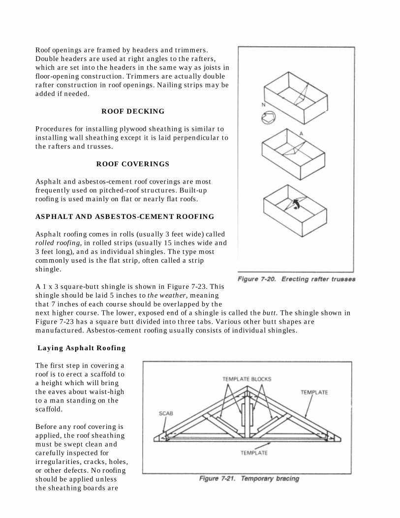
After the rafters areassembled into trusses, theymust be placed on thebuilding (Figure 7-20, page 7-14). Assemble the first set ofrafters either in the endsection of the building or atthe center. Raise raftertrusses into position (byhand) and nail them intoplace with 16d nails.(Temporary workbenchesmay be built for the workersto stand on while erectingtrusses.) These trusses mustbe temporarily braced at theend section of the buildinguntil the sheathing is applied.Knee braces are not used onevery rafter truss unless

needed. Install trusses as follows:
Step 1. Mark the proper positions of all truss assemblies on the top plate. The marks must showthe exact position on the face of all rafters (such as south or north).
Step 2. Rest one end of a truss assembly, peak down, on an appropriate mark on the top plate onone side of the structure.
Step 3. Rest the other end of the truss on the corresponding mark of the top plate on the other sideof the structure.
Step 4. Rotate the assembly into position using a pole or rope.
Step 5. Line up and secure the rafter faces flush against the marks.
Step 6. Raise, align, and nail the three assemblies into position. Nail temporary 1 x 6 braces acrossthese three assemblies. Repeat with the other assemblies as they are brought into position. Checkthe rafter spacing at the peaks as the braces are nailed on.
Step 7. Braces may be used as a platform when raising those trusses for which there is not enoughroom for rotation (Figure 7-21).
ROOF OPENINGS
Major roof openings are those that interrupt the normal run of rafters or other roof framing. Suchopenings may be for ventilators, chimneys, trap-door passages, or skylight or dormer windows.Figure 7-22 shows roof-opening construction.
Roof openings are framed by headers and trimmers.Double headers are used at right angles to the rafters,which are set into the headers in the same way as joists infloor-opening construction. Trimmers are actually doublerafter construction in roof openings. Nailing strips may beadded if needed.
ROOF DECKING
Procedures for installing plywood sheathing is similar toinstalling wall sheathing except it is laid perpendicular tothe rafters and trusses.
ROOF COVERINGS
Asphalt and asbestos-cement roof coverings are mostfrequently used on pitched-roof structures. Built-uproofing is used mainly on flat or nearly flat roofs.
ASPHALT AND ASBESTOS-CEMENT ROOFING
Asphalt roofing comes in rolls (usually 3 feet wide) calledrolled roofing, in rolled strips (usually 15 inches wide and3 feet long), and as individual shingles. The type mostcommonly used is the flat strip, often called a stripshingle.
A 1 x 3 square-butt shingle is shown in Figure 7-23. Thisshingle should be laid 5 inches to the weather, meaningthat 7 inches of each course should be overlapped by thenext higher course. The lower, exposed end of a shingle is called the butt. The shingle shown inFigure 7-23 has a square butt divided into three tabs. Various other butt shapes aremanufactured. Asbestos-cement roofing usually consists of individual shingles.
Laying Asphalt Roofing
The first step in covering aroof is to erect a scaffold toa height which will bringthe eaves about waist-highto a man standing on thescaffold.
Before any roof covering isapplied, the roof sheathingmust be swept clean andcarefully inspected forirregularities, cracks, holes,or other defects. No roofingshould be applied unlessthe sheathing boards are

absolutely dry.
An underlay of roofing felt is first applied tothe sheathing. Roofing felt usually comes in3-foot-wide rolls and should be laid with a 2-inch top lap and a 4-inch side lap.
Bundles of shingles should be distributedalong the scaffold before work begins. Thereare 27 strips in a bundle of 1 x 3 asphaltstrip shingles. Three bundles will cover 100square feet.
After the first course at the eaves (thestarter course) is laid by inverting the firstcourse of shingles or the starter strip ofmineral-surfaced roll roofing, each coursethat follows is begun by stretching aguideline or by snapping a chalk line fromedge to edge. This positions the course.
Figure 7-24 shows the method of laying a 1 x 3 asphalt strip-shingle roof. Strip shingles should benailed with 1-inch copper or hot-dipped, galvanized roofing nails, two to each tab; this means sixnails to each full strip. Nails should be placed about 6 1/2 inches from the butt edges to ensure thateach nail will be covered by the next course (blind-nailing) and driven through two courses.
An asbestos-cement roof is laid in about the same way as the asphalt strip shingles.
Applying Shingles at Hips and Valleys
One side of a hip or valley shingle must be cut at an angle to obtain an edge line that willmatch the line of the hip or valley rafter. One way to cut these shingles is to use a patternmade as follows:
Select a piece of 1 x 6 material about 3 feet long. Determine the unit length of a common rafter inthe roof. Set the framing square back up on the piece to the unit run of a common rafter on thetongue and the unit length of a common rafter on the blade, as shown in Figure 7-25, A. Draw aline along the tongue. Saw the piece along this line and use it as a pattern to cut the shingles as

shown in Figure 7-25, B.
Installing Flashing
Places especially susceptible to leakage in roofs and outside walls are made watertight by theinstallation of flashing. Flashing is sheets or strips of a watertight, rustproof material (such asgalvanized sheet or sheet copper alloy for valleys and felt for hips). Flashing deflects water fromplaces that are susceptible to leakage. The places in a roof most subject to leakage are the linesalong which adjoining roof surfaces intersect (such as the lines followed by ridges, hips, andvalleys) and the lines of intersection between roof surfaces and the walls of dormers, chimneys,skylights, and the like.
Ridge lines and hip lines naturally tend to shed water; therefore, they are only moderatelysubject to leakage. A strip of felt paper usually makes a satisfactory ridge or hip flashing.The ridge or hip is then finished as shown in Figure 7-26. Squares are made by cuttingshingles into thirds. The squares are then blind-nailed to the ridge or hip as shown in
Figure 7-26.

Since water gathers in the roof valleys, they are more subjectto leakage. Valley flashing varies with the manner in whichthe valley is to be finished. There are two common types ofvalley finish: the open valley and the closed valley.
Figure 7-27 shows part of an open valley. The roofcovering does not extend across the valley. The flashingconsists of a prefabricated piece of galvanized iron,copper, zinc, or similar metal, with a splash rib or ridgedown the center and a small crimp at the edges. Theflashing is nailed down to the valley, with nails driven inthe edges (outside the crimps), as shown in Figure 7-27.Care must be taken not to drive nails through theflashing inside the crimps, to avoid leakage. Figure 7-28, page 7-18, shows an open valleyusing rolled roofing.
In the closed valley, the roof covering extends across the valley. Sheet metal flashing is cut intosmall sheets measuringabout 18 x 10 inches,called shingle tins. Thisflashing is laid under eachcourse of shingles, along thevalley, as the course is laid.After the first course of thedouble course at the eavesis laid, the first sheet offlashing is placed on top ofit. The second course is laidover this one so that themetal is partly covered bythe next course. Thisprocedure is continued allthe way up the valley.
Shingle tins measuring about 5 x 7inches may also be used to lay flashingup the side walls of dormers, chimneys,skylights, and similar openings. Each tinis bent at a right angle so that part of thetin extends up the side wall and the restlies flat on the roof covering. This iscalled side flashing. In addition to theside flashing, a dormer, chimney, orskylight has a strip of flashing called anapron along the bottom of the outer wallor face. A chimney or skylight has asimilar strip, called the saddle 1?ashing,along the bottom of the inner wall or face.Figure 7-29 shows vertical wall flashing.

BUILT-UP ROOFING MATERIAL
The following building papers are used on a built-up roof. Their purpose is to prevent the seepageof bitumen through roof sheathing on which a built-up roof has been applied.
• Rosin paper is a felt paper, usually pale red, filled with rosin compound.• Kraft paper is a light brown paper that is usually glazed.• Sisal kraft consists of two layers of glazed kraft paper with a center section of sisal embedded in
a black bituminous compound and laminated by heat and pressure.• Roofing felt is a felt paper that has been saturated with a bituminous compound (heavy pitch or
asphalt oils). The basicingredients are usually eitherasbestos or rag felts. The rollmay vary from 32 to 36 incheswide. Weights for built-uproofing vary from 15 to 65pounds per square. The 15-pound felt is most commonlyused because of its lightweight.
A binder is used to bond theroofing felt together and form awatertight seal. Asphalt andcoal tar are the two main typesof bituminous binders used.Drying out of the binder causesdeterioration of built-up roofs.If this did not happen, a built-up roof would last indefinitely. Asphalt is the preferredbinder. It is used on roofs sloping up to 6 inches per foot (1/4 pitch). Asphalt has a meltingpoint of 350' to 41 0°F. A roof covered with asphalt should be protected with a covering ofslag, gravel, or other protective material. Tar has a lower melting point (300° to 350°F)than asphalt, so it will move more easily; therefore, it is not recommended for roofs having aslope of more than 3 inches per foot (1/8 pitch).
Aggregate, crushed stone, or gravel from 1/4 to 5/8 inch in diameter is embedded in a coat ofasphalt or tar to hold the roof covering down. It also prevents the binding from disintegratingbecause of the weather.
Gravel stops on slag or gravel-surfaced roofs, and metal-edge strips on smooth-surfacedbuilt-up roofs are used to finish all exposed edges and eaves to prevent wind from gettingunder the edges and causing blowoffs. The gravel stop also prevents the loss of gravel orslag off the edge of the roof. The flashing flange of the gravel stop or edge strip is placedover the last ply of felt. It should be nailed securely to the roof deck and double felt stripped.Then the finished coat of bitumen and surfacing or cap sheet should be applied. The lip of thegravel stop should extend a minimum of 3/4 inch above the roof deck. The lip of the edge stripshould be a maximum of 1/2 inch above the deck. Both should be securely fastened to the fasciaboard.

RE ROOFING
This section provides information on reroofing for the following types of roofs: asphalt-shingleroofs, asphalt-prepared roll roofings, built-up roofs, slate roofs, tile roofs, asbestos-cement roofs,metal roofs, and wood-shingle roofs.
ASPHALT-SHINGLE ROOFS
The following types of asphalt strip shingles are used for reroofing hospitals and mobilization-typebuildings with pitched roofs. These shingles are applied directly over the existing roll roofings.
Standard-weight shingles should be four-tab, 10 x 36 inches, and intended for a 4-inch maximumexposure. Weight per square (100 square feet) applied should be approximately 210 pounds.Shingles are fastened with 1 1/4- or 1 1/2-inch nails with heads having a minimum diameter of 3/8inch. Zinc-coated nails are best.
Thick-butt shingles should be three-tab, 1 x 3 feet, and intended for a 5-inch maximum exposure.The entire surface of the shingles should be covered with mineral granules. The bottom part ofeach shingle, including the part intended to be exposed and a section at least 1 inch above thecutout sections, should be thicker than the remainder of the shingle. Weight per square appliedshould be approximately 210 pounds. Shingles are fastened with 1 1/2- or 1 3/4-inch nails withheads having a minimum diameter of 3/8 inch. Zinc-coated nails are best.
Preparation of Roof Decks
The following steps assume that the roof decks are covered with smooth or mineral-surfaced, asphalt-prepared roofing and that the shingles will be applied directly over theexisting roofing.
Step 1. Drive in all loose and protruding nails flush with the existing roll roofing.
Step 2. Cut out all vertical and horizontal buckles and wrinkles in the existing roofing. Nail downthe edges of the cuts with 3/4-inch or 1-inch roofing nails so that the entire roof deck is smooth.
Step 3. If shingles are applied over smooth-surfaced roofing or over mineral-surfaced roofing whichdoes not match the shingles, apply an 18-inch starting strip of mineral-surfaced roll roofing at theeaves. Use roofing surfaced with granules of the same type and color as the shingles.
Step 4. Before the strips are applied, unroll them carefully and lay them on a smooth, flat surfaceuntil they lie perfectly flat.
Step 5. Nail starter strips at the top at about 18-inch intervals. The lower edge, bent down andnailed to the edge of the sheathing board, should extend about 3/4 inch beyond the edge of theboard to form a drip edge. Space the nails in the edge of the sheathing board 6 inches apart.
A starter strip need not be used if the shingles are the same color as the existing roofing and theexisting roofing is not buckled. Figure 7-30, page 7-20, shows an example of roof replacement.
Application of Shingles
Shingles are attached in different ways, depending on the type.

Standard-Weight, Four-Tab, 10- x 36-Inch Shingles. Start the first course with a full shingleplaced so that one edge, cut off flush with the tab, is also flush with the side of the roof. Thebottoms of the tabs are placed flush with the eaves. Place nails about 3/4 inch above each cutout
section and in the same relative position at each end of the shingle. Use two nails at every cutout.Nail at the center first, then above the cutout sections nearest the center, and finally at the ends.Nailing may start at one end and proceed regularly to the other. Complete the first course withfull-width shingles applied so that the ends barely touch each other.
Start the second course with a shingle from which half a tab has been cut. Place it so that thebottoms of the tabs are flush with the tops of the cutout sections of the shingle in the first course.Complete this course with full-width shingles.
Start the third course with a shingle from which one tab has been cut; the fourth with onefrom which one and one-half tabs have been cut; and so on, until eventually a full shingleis used again.
Thick-Butt, Three-Tab Shingles. Follow the same method described for standard shingles.Always nail these shingles through the thick part, about 3/4 inch above the cutout sections. Theimportance of nailing through the thick part of asphalt shingles cannot be emphasized toostrongly. Practically all difficulties experienced with asphalt shingles on Army buildings haveresulted from nailing the shingles too high.
Hips and Ridges. Finish hips and ridges with individual shingles furnished especially by themanufacturer or with shingles cut from strip shingles. Hips and ridges may also be finished with astrip of mineral-surfaced roofing 9 inches wide, bent equally on each side and nailed on 2-inchcenters 3/4 inch from the edges.

Open Valleys. Open valleys may be flashed with 90-pound, 18-inch-wide mineral-surfacedasphalt roll roofing (Figure 7-31) placed overthe valley underlayment. It is centered in thevalley with the surfaced side down and thelower edge cut flush with the eaves flashing.When it is necessary to splice the material,the ends of the upper segments are laid tooverlap the lower segments 12 inches and aresecured with asphalt plastic cement. A 36-inch-wide strip is placed over the first strip,centered in the valley with the surfaced sideup and secured with nails.
Before shingles are applied, a chalk line issnapped on each side of the valley for its fulllength. The lines should start 3 inches fromthe valley on both sides. The chalk linesserve as a guide in trimming the shingleunits to fit the valley. The upper corner ofeach end shingle is clipped to direct waterinto the valley (Figure 7-31). Each shingle is cemented to the valley lining with asphalt cement toensure a tight seal. No exposed nails should appear along the valley flashing.
Closed Valleys. Closed valleys can be used only with strip shingles (Figure 7-32). This methodhas the advantage of doubling the coverage of the shingles throughout the length of the valley. Avalley lining made from a 36-inch-wide strip of 55-pound (or heavier) roll roofing is placed over thevalley underlayment and centered in the valley (Figure 7-32).
Valley shingles are laid over the lining by either of two methods:
• Applying both roof surfaces at the same time, with each course in turn woven over the valley.• Covering each surface to the point approximately 36 inches from the center of the valley and
the valley shingles woven in place later.
Either way, the first course at the valley islaid along the eaves of one surface over thevalley lining and extended along theadjoining roof surface for at least 12 inches.The first course of the adjoining roof surfaceis then carried over the valley on top of thepreviously applied shingle. Each coursethereafter is laid alternately, weaving thevalley shingles over each other.
The shingles are pressed tightly into thevalley and nailed in the usual mannerexcept that no nail should be located closerthan 6 inches to the valley centerline andtwo nails are used at the end of eachterminal strip (Figure 7-32).

ASPHALT-PREPARED ROLL ROOFINGS
There are two types of asphalt-prepared roll roofing: mineral-surfaced and smooth-surfaced.
Mineral-Surfaced Roll Roofing
Mineral-surfaced, asphalt-prepared, two-ply roofing should consist of a layer of 15-pound asphalt-saturated felt and two plies of roll roofing, cemented together with hot asphalt. Cut roll-roofingmaterial into lengths of 18 or 20 feet, stacked free from wrinkles and buckles in protected piles.Maintain the roofing material at a temperature of at least 50°F for 24 hours before laying.
First, cover the roof areas with a layer of 15-pound asphalt-saturated felt, with all joints lapped 2inches. Nail as required to prevent blowing off during the application of roofing. Next, lay eitherplain, dry unsurfaced roofing or dry mineral-surfaced roofing as a starter sheet. Lay this upsidedown parallel to and flush with the eaves. Nail through tin or fiber disks on 12-inch staggeredcenters; that is, with one row of nails on 12-inch centers placed not more than 2 inches from thelower edge, and with a second row on 12-inch centers staggered with respect to the first and about8 inches above the first.
Over the lower half of this sheet, apply a uniform coating of hot asphalt at the rate of 30 poundsper 100 square feet. Place the first sheet of roll roofing in the asphalt. Cover the entire roof area,lapping each successive sheet, to obtain a two-ply roofing with a 2-inch head lap. Cement the loweror mineral-surfaced portion of each sheet with hot asphalt to the preceding sheet. Nail the edgethrough tin or fiber disks on 12-inch staggered centers. Use two rows of nails. Place the first rowon 12-inch centers not more than 2 inches above the mineral surfacing and the second row on 12-inch centers staggered with respect to the first and about 8 inches above the first.
Perform the work in such a way that no fastenings or asphalt will show on the finishedsurface. Apply the asphalt immediately before unrolling the sheet of roofing. Do not applythe asphalt more than 3 feet ahead of the roll. Step the edge of each sheet into the asphaltso that all laps are securely sealed. Place the end laps 6 inches in width with theunderlying edges nailed on 6-inch centers, asphalt-cement the overlying edges, and stepdown firmly. Place one ply of roofing at eaves and edges, turn down neatly, and secure it with awood member nailed on 8-inch centers.
Smooth-Surfaced Roll Roofing
Before laying the roll-roofing material, cut it into 18-or 20-foot lengths. Stack them free of wrinklesand buckles in protected piles, and maintain them at a temperature of at least 50°F for 24 hours.
For TO construction, apply single-ply roll roofing horizontally with at least 4-inch side laps and 6-inch end laps. Nail the underlying edges of laps through tin or fiber disks on 6-inch centers.Cement overlying laps with hot asphalt or an approved cold-applied sealing compound. Step downfirmly on the edges to provide proper adhesion. Double the roofing over the ridge with at least 4-inch laps. Turn roofing down neatly at eaves and edges. Nail the roofing in place on 6-inch centers.Figure 7-33 shows an example.
BUILT-UP ROOFS
Buildings with roofs of relatively low pitch (less than 2 inches per foot), originally roofed withasphalt-prepared roll roofings, should be reroofed with smooth-surfaced asphalt built-up roof1ng or

with coal-tar-pitch built-up roofing.
Use smooth-surfaced asphalt built-up roofing on buildings with original smooth-surfaced rollroofing.
Use asphalt built-up roofing or coal-tar-pitch built-up roofing on mobilization-type buildings withroofs of relatively low pitch (usually 1/2 inch per foot), originally roofed with wide-selvage, mineral-surfaced roll roofing. If the roof is nearly flat so water collects and stands, the latter type of roofingis best. Asphalt roofs may be smooth- or mineral-surfaced. Coal-tar-pitch roofs must be mineral-surfaced.

Asphalt Built-Up Roofs
Prepare the roof deck by driving in all loose and protruding nails and cutting out all

buckles and wrinkles. Then apply a three-ply, smooth-surfaced asphalt built-up roof asfollows:
Step 1. Lay one layer of 15-pound asphalt-saturated felt over the entire surface. Lap each sheet 3inches horizontally and vertically and nail the laps on 12-inch centers. Also nail through the centerof each sheet on 12-inch centers staggered with respect to the nails at the horizontal laps. Usenails long enough to penetrate into the sheathing at least 3/4 inch. They should be driven throughtin or hard fiber disks.
Step 2. Mop the entire surface with a uniform coating of hot asphalt, using 25 pounds per 100square feet.
Step 3. Over this coating of asphalt, lay two additional layers of 15-pound, 36-inch, asphalt-saturated felt. Lap each sheet 19 inches, and lap the sheet ends not less than 6 inches. Nail thesefelts through tin or hard fiber disks 1 inch from the back edge on 12-inch centers. Use nails longenough to penetrate into the wood sheathing at least 3/4 inch.
Step 4. Mop each of these sheets the full width of the lap with hot asphalt, using 25 pounds per 100square feet.
Step 5. Apply a uniform mopping of hot asphalt over the entire surface, using 30 pounds per 100square feet of roof surface.
NOTE: Do not heat asphalt above 400°F. Lay the felt while the asphalt is hot, taking careto keep the surface free from wrinkles or buckles.
The materials needed per 100 square feet of roof surface for the three-ply, smooth-surfaced asphaltbuilt-up roof are
• Asphalt: 80 pounds.• Asphalt-saturated felt: 45 pounds.
If the existing roofing is so rough that it is impossible to obtain a smooth surface by themethod described above, remove the original roofing and apply a three-ply, smooth-surfaced,asphalt built-up roof. Substitute 30-pound asphalt-saturated felt for the 15-pound felt originallyspecified.
If a slag or gravel-surfaced roof is desired for mobilization-type buildings, at step 5 above, apply 45pounds of hot asphalt instead of 30 pounds per 100 square feet. Into this hot coating, place 300pounds of roofing slag or 400 pounds of roofing gravel per 100 square feet of roof surface.
Coal-Tar-Pitch Built-Up Roofs
Prepare the roof surface as previously described, then apply a three-ply, coal-tar-pitch built-up roofas follows:
Step 1. Apply one layer of 15-pound coal-tar-saturated felt over the entire roof surface. Prepare itas described in step 1 of "Asphalt Built-Up Roofs."
Step 2. Mop the entire surface with a uniform coating of hot coal-tar pitch, using 30 pounds per100 square feet.

Step 3. Over this coating of coal-tar pitch, lay two additional layers of 15-pound coal-tar-saturatedfelt 36 inches wide. Lap each sheet 19 inches over the preceding sheet. If 32-inch felt is used, lapeach sheet 17 inches. Nail the felt 1 inch from the back edge on 12-inch centers through tin or hardfiber disks. Use nails long enough to penetrate into the wood sheathing at least 3/4 inch. Lap theends of the sheets at least 6 inches.
Step 4. Mop each sheet the full width of the lap with hot coal-tar pitch, using 25 pounds per 100square feet.
Step 5. Apply a uniform pouring of hot coal-tar pitch over the entire surface. Use 55 pounds per100 square feet. While the pitch is hot, place over it 300 pounds of roofing slag or 400 pounds ofroofing gravel per 100 square feet.
The materials required per 100 square feet of roof surface are
• Coal-tar pitch: 110 pounds.• Coal-tar-saturated felt: 45 pounds.• Roofing slag: 300 pounds.
or
• Roofing gravel: 400 pounds.
NOTE: Do not heat the coal-tar pitch above 375°F. Lay the felt while the coal-tar pitch isstill hot, taking care to keep the surface free from wrinkles or buckles.
SLATE ROOFS
Very old slate roofs sometimes suffer failure because of the nails used to fasten the slates. In suchcases, remove and replace the entire roof, including the felt underlay materials. Remove or drive inany protruding nails. Make every effort to obtain a smooth, even deck similar to the original one.Apply 30-pound asphalt-saturated felt horizontally over the entire roof deck. Lap the sheets notless than 3 inches. Turn them up 6 inches or more on vertical surfaces and over 12 inches or moreon ridges and hips. Secure the sheets along laps and exposed edges with large-head roofing nailsspaced about 6 inches apart.
Re-lay all original slates that are in good condition. Replace defective slates with new slates of thesame size, matching the original color and texture as nearly as possible.
Recommended slate sizes for large new buildings are 20 or 22 inches long; for small new buildings,16 or 18 inches long. Use slates of uniform length, in random widths, and punched for a head lap ofnot less than 3 inches.
Lay roof slates with a 3-inch head lap. Fasten each slate with two large-head slating nails anddrive them so that their heads just touch the slate. Do not drive the nails "home." The opposite istrue of wood shingles; therefore, workmen accustomed to laying wood shingles must nail slatecarefully.
Bed all slates in an approved elastic cement on each side of hips and ridges within 1 foot of the topand along gable rakes within 1 foot of the edge. Match slate courses on dormer roofs with those onthe main roof. Lay slate with open valleys.

TILE ROOFS
Before reroofing with tiles, restore the roof deck as nearly as possible to its original condition.Replace defective boards and apply asphalt-saturated felt (30-pound type) or prepared roofing. Lapthe sheets not less than 3 inches. Turn them up on vertical surfaces for at least 6 inches and overridges and hips for at least 12 inches. Secure the sheets along laps and exposed edges with large-head roofing nails spaced about 6 inches apart.
Tiles must be free from fire cracks or other defects that will impair the durability, appearance, orweather tightness of the finished roof. Special shapes are provided for eaves starters, hips, ridges,top fixtures, gable rakes, and finials. Special shapes for field tile at hips and valleys may befactory-molded or may be job cut from whole tile and rubbed down to clean, sharp lines. Roof tilesfor use on Army buildings are generally furnished in one or more of the following types:
• Mission tiles are straight-barrel-type, molded to a true arc and machine-punched for one nailand a 3-inch head lap. Use regular cover tile for ridges and hips. Finish with plain missionfinials. Eaves closures and hip starters are available. Approved sizes are generally 8 incheswide by 14 to 18 inches long.
• Spanish tiles are S-shaped and machine-punched for two nails and a 3-inch head lap. Eavesclosures and hip starters are available. Use mission-type cover tiles for hips and ridges.Approved sizes are generally 9 1/2 to 12 inches wide by 12 to 18 inches long.
• Slab-shingle tiles are the flat, noninterlocking type, punched for two nails and a 2-inchhead lap. Approved sizes are 6 to 10 inches wide, 15 inches long, and 1/2 inch thick.
Mission and Spanish Tiles
Before starting to lay tiles, mop the wood nailing strips with hot asphalt. Fill the spaces in back ofthe cant strips with asphalt cement. Lay tiles with open valleys. Set eaves closures back 3 inchesfrom the lower edge of eaves tiles. Lay pan tiles with uniform exposure to the weather. Lay covertiles in a uniform pattern, except where otherwise necessary to match existing roofs. Give all tilesa minimum lap of 3 inches and extend pan tiles 1 inch over the rear edge of the gutter.
Cut the tiles so that they meet projections with finished joints and point them up with roofer'scement. Waterproof the spaces between field tiles and wood nailing strips at ridges and hips with afill of roofer's cement. Fit all tiles properly and then secure them with nails long enough topenetrate at least 1 inch into the wood base.
Fill spaces between pan and cover tiles in the first row at the eaves with solid cement mortar madeof one part Portland cement, three parts fine sand, and enough clean water to form a plastic mix.Wet all tiles before applying mortar, then press them firmly into the mortar bed. Match the tilecourses on dormer roofs with those on the main roof. Cut surplus mortar off neatly. Point up allopen joints. Remove loose mortar from exposed surfaces.
Where hurricane winds can be expected, consider reinforcing tile roofs by laying all field tiles inPortland cement mortar. To do this, fill the ends of tiles at eaves, hips, ridges, rakes, and spacesbeneath ridges solid with cement mortar. Fill the full width of laps between the tiles, both paralleland perpendicular to the eaves, with cement mortar.
Slab-Shingle Tiles

Lay slab-shingle tiles with a 2-inch head lap. Secure each tile with two large-head roofingnails. Double the tiles at eaves and project them 1 inch over the rear edge of gutters. Lay alltiles within 1 foot of hips, ridges, and abutting vertical surfaces in roofer's cement. Lay 10- or 12-inch tiles with 1-inch head lap on the sides of dormers. Match the tile courses on dormer roofs withthose on the main roof. Lay tile roofs with open valleys.
ASBESTOS-CEMENT ROOFS
Before reroofing with asbestos-cement shingles, restore the roof deck as nearly as possible to itsoriginal condition. Replace defective boards, and apply new 30-pound asphalt-saturated felt orprepared roofing in horizontal courses. Lap the sheets not less than 3 inches. Turn them up atleast 6 inches on vertical surfaces and over at least 12 inches on ridges and hips. Secure thesheets along laps and exposed edges with large-head roofing nails spaced about 6 inches apart.
Re lay all asbestos-cement shingles that are in good condition. Replace defective shingles with newshingles of the same size, matching the originals as nearly as possible in color and texture.
Lay each shingle with a 2-inch head lap and secure it with two large-head slating nails. Drive thenails so that their heads just touch the shingles. Do not drive the nails "home" as in laying woodshingles. Bed all shingles on each side of hips and ridges within 1 foot of the edge in an approvedelastic slater's cement. Project the shingles 1 inch over the rear edges of gutters. Lay shingles witha 1-inch head lap on sides of dormers. Match the shingle courses on dormer roofs with those on themain roof. Lay shingles with open valleys.
METAL ROOFS
To conserve critical materials, replace metal roofs with nonmetallic roofing materials.
WOOD-SHINGLE ROOFS
When old roofing is removed—
• Restore the roof deck as nearly as possible to its original condition. Replace rottedboards and pull out or drive down all protruding nails.
• Install flashings and apply new shingles.
If the existing shingle roofs can be made smooth and can be nailed properly, apply new woodshingles directly over weathered wood-shingle roofs. Reroof over existing wood shingles as follows:
Step 1. Nail down or cut off curled and warped shingles. Nail loose shingles securely, and removeor drive down protruding nails.
Step 2. Cut off the old first-course shingles at the eaves just below the butts of the second course.Replace them with a 1 x 3 or 1 x 4 strip nailed flush with the eaves line.
Step 3. Cut back the shingles at the gable ends about 3 inches. Replace them with a 1 x 2, 1 x 3, or1 x 4 strip nailed flush with the gable end.
Step 4. Remove weathered shingles at the ridge. Replace them with a strip of beveled siding, thinedge down, to provide a solid base for nailing the ridge shingles. Treat the hip the same as theridges.

Step 5. Fill open valleys with wooden strips level with the old shingle surface or with a narrowstrip placed across the 'V" of the valley to act as a support for new flashings.
Step 6. Inspect flashings carefully. Replace terne and galvanized flashings. Reuse old flashings ifthey are in good condition.
Step 7. Use the following nails in applying shingles over an existing roof:
• 5d box or special overroofing nails, 14-gauge, and 1 3/4 inches long for 16- and 18-inch shingles.• 6d nails, 13-gauge, and 2 inches long for 24-inch shingles.
One square of roofing will need about 3 1/2 pounds of nails.
Step 8. Apply new shingles as recommended by their manufacturer.