type test certificate 615 series ansi - abb group · type test certificate. description type test...
TRANSCRIPT
—RELION® PROTECTION AND CONTROL
615 series ANSIType Test Certificate


Document ID: 1MAC057558-TCIssued: 2019-06-07
Revision: BProduct version: 5.0 FP1
© Copyright 2019 ABB. All rights reserved


Table of contents
Section 1 General..................................................................................3
Section 2 Test objects........................................................................... 5
Section 3 Type tests..............................................................................7
Table of contents
615 series ANSI 1Type Test Certificate

2

Section 1 General
Product/type Protection and control product series 615
Result The equipment under test has been tested according to the relevant parts of thestandards and it has fulfilled the specified requirements in all parts of the type test. Noerroneous operation or malfunction occurred, and no electrical damage could beobserved.
Manufactured by ABB Oy Distribution SolutionsP.O. Box 699FI-65101, Vaasa, FINLANDPhone +358 10 22 11Fax +358 10 22 41094
Author/department Mika Kortesniemi/RSSType testing
Date of issue 2016-05-20
Approved by ABB Inc.Distribution Solutions, Distribution Automation
Edgar P. FloresProduct Manager
Bryan L. TauzerQuality Manager
References ANSI publications
Application Manual, RED615 1MAC807603-MB
Application Manual, REF615 1MAC109016-MB
Application Manual, REG615 1MAC859072-MB
Application Manual, REM615 1MAC254299-MB
Application Manual, RET615 1MAC206062-MB
Cyber Security Deployment Guideline, 615 series 1MAC052704-HT
DNP3 Communication Protocol Manual, 615 series 1MAC052479-MB
DNP3 Point List Manual, 615 series 1MAC059432-MB
Engineering Manual, 615 series 1MAC108982-MB
IEC 61850 Engineering Guide, 615 series 1MAC053584-RG
Installation Manual, 615 series 1MAC051065-MB
Table continues on next page
1MAC057558-TC B Section 1General
615 series ANSI 3Type Test Certificate
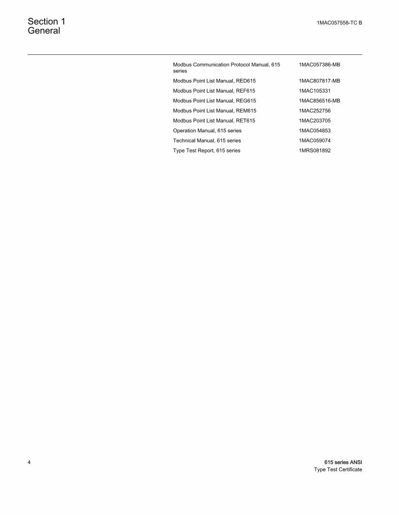
Modbus Communication Protocol Manual, 615series
1MAC057386-MB
Modbus Point List Manual, RED615 1MAC807817-MB
Modbus Point List Manual, REF615 1MAC105331
Modbus Point List Manual, REG615 1MAC856516-MB
Modbus Point List Manual, REM615 1MAC252756
Modbus Point List Manual, RET615 1MAC203705
Operation Manual, 615 series 1MAC054853
Technical Manual, 615 series 1MAC059074
Type Test Report, 615 series 1MRS081892
Section 1 1MAC057558-TC BGeneral
4 615 series ANSIType Test Certificate
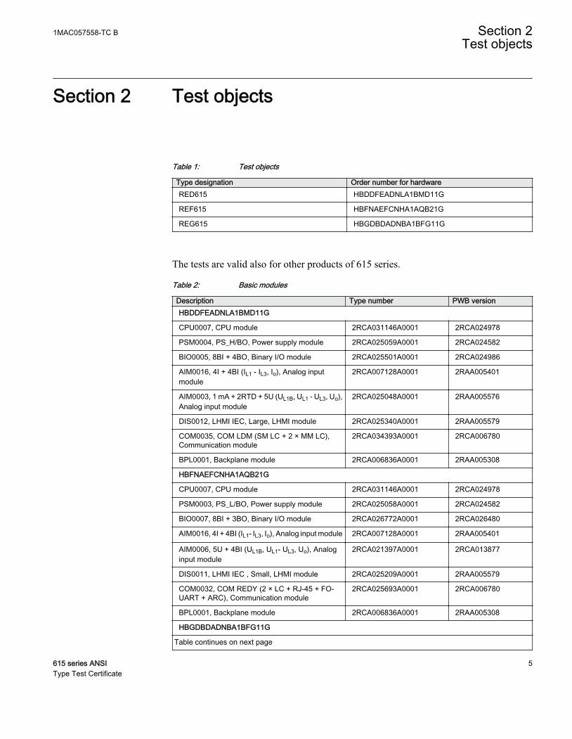
Section 2 Test objects
Table 1: Test objects
Type designation Order number for hardwareRED615 HBDDFEADNLA1BMD11G
REF615 HBFNAEFCNHA1AQB21G
REG615 HBGDBDADNBA1BFG11G
The tests are valid also for other products of 615 series.
Table 2: Basic modules
Description Type number PWB versionHBDDFEADNLA1BMD11G
CPU0007, CPU module 2RCA031146A0001 2RCA024978
PSM0004, PS_H/BO, Power supply module 2RCA025059A0001 2RCA024582
BIO0005, 8BI + 4BO, Binary I/O module 2RCA025501A0001 2RCA024986
AIM0016, 4I + 4BI (IL1 - IL3, Io), Analog inputmodule
2RCA007128A0001 2RAA005401
AIM0003, 1 mA + 2RTD + 5U (UL1B, UL1 - UL3, Uo),Analog input module
2RCA025048A0001 2RAA005576
DIS0012, LHMI IEC, Large, LHMI module 2RCA025340A0001 2RAA005579
COM0035, COM LDM (SM LC + 2 × MM LC),Communication module
2RCA034393A0001 2RCA006780
BPL0001, Backplane module 2RCA006836A0001 2RAA005308
HBFNAEFCNHA1AQB21G
CPU0007, CPU module 2RCA031146A0001 2RCA024978
PSM0003, PS_L/BO, Power supply module 2RCA025058A0001 2RCA024582
BIO0007, 8BI + 3BO, Binary I/O module 2RCA026772A0001 2RCA026480
AIM0016, 4I + 4BI (IL1- IL3, Io), Analog input module 2RCA007128A0001 2RAA005401
AIM0006, 5U + 4BI (UL1B, UL1- UL3, Uo), Analoginput module
2RCA021397A0001 2RCA013877
DIS0011, LHMI IEC , Small, LHMI module 2RCA025209A0001 2RAA005579
COM0032, COM REDY (2 × LC + RJ-45 + FO-UART + ARC), Communication module
2RCA025693A0001 2RCA006780
BPL0001, Backplane module 2RCA006836A0001 2RAA005308
HBGDBDADNBA1BFG11G
Table continues on next page
1MAC057558-TC B Section 2Test objects
615 series ANSI 5Type Test Certificate

Description Type number PWB versionCPU0007, CPU module 2RCA031146A0001 2RCA024978
PSM0004, PS_H/BO, Power supply module 2RCA025059A0001 2RCA024582
BIO0005, 8BI + 4BO, Binary I/O module 2RCA025501A0001 2RCA024986
AIM0015, 7I (I0 0.2/1 A, IL1 - IL3, IL1B - IL3B), Analoginput module
2RAA005920A0004 2RAA005786
AIM0006, 5U + 4BI (UL1b, UL1 - UL3, Uo), Analoginput module
2RCA021397A0001 2RCA013877
DIS0012, LHMI IEC , Large, LHMI module 2RCA025340A0001 2RAA005579
COM0005, COM IEC (RJ-45 + ARC),Communication module
2RAA005844A0001 2RAA005402
BPL0001, Backplane module 2RCA006836A0001 2RAA005308
Type tests are performed on IEC LHMI module DIS0012. The test resultsare also applicable for ANSI LHMI module DIS0014, since the PCBA isthe same in both ANSI and IEC LHMI.
Section 2 1MAC057558-TC BTest objects
6 615 series ANSIType Test Certificate

Section 3 Type tests
Table 3: Inspection of mechanical structure
Description Reference ResultMarkings and mechanical structure IEC 60255-1
IEC 60255-27OK
Enclosure class (flush-mounted) IEC 60529 IP 54 front sideIP 10 rear side,connection terminals
Clearances and creepage distances IEC 60255-5IEC 60255-27
OK
Table 4: Overload and input tests
Description (IEC 60255-1 and IEC 60255-27) RequirementRated current, In 0.2/1 A1) 1/5 A2)
Thermal withstand capability
• Continuously• For 1 s
4 x In=4 A100 x In=100 A
4 x In=20 A100 x In=500 A
Dynamic current withstand
• Half-wave value 250 x In=250 A 250 x In=1250 A
Input impedance < 100 mΩ < 20 mΩ
Rated voltage, Un 60...210 V AC
Burden < 0.05 VA
Voltage withstand
• Continuously• For 10s
240 V AC360 V AC
Current sensor input, rated voltage (in secondaryside) 75...2812.5 mV
Continuous voltage withstand 125 V
Input impedance at 50/60 Hz 2-3 MΩ
Voltage sensor input, rated voltage 6...30 kV
Table continues on next page
1MAC057558-TC B Section 3Type tests
615 series ANSI 7Type Test Certificate

Description (IEC 60255-1 and IEC 60255-27) RequirementContinuous voltage withstand 50 V
Input impedance at 50/60 Hz 3 MΩ
Binary inputs
• Operational range• Current drain• Power consumption
19.2...300.0 VDC1.6...1.9 mA31.0...570.0 mW
1) Residual current2) Residual current and/or phase current
Table 5: Power supply module tests
Test Description ResultAuxiliary voltage
(IEC 60255-1, IEEEC37.90-2005)
• PS_H 38...300 VDC38...264 VAC
No influenceNo influence
• PS_L 12...72 VDC No influence
Immunity to voltage dips(IEC 60255-11)
• PS_H Residual voltage 0%:
38...300 VDC 0...50 ms, normal operation>50 ms, restart
Residual voltage 40%:
38 VDC300 VDC
200 ms, restart200 ms, normal operation
Residual voltage 70%:
38 VDC300 VDC
500 ms, restart500 ms, normal operation
Residual voltage 0%:
38 VAC 0...46 ms, normal operation>46 ms, restart
residual voltage 0%:
48...264 VAC 0...58 ms, normal operation>58 ms, restart
Residual voltage 40%:
38 VAC264 VAC
200 ms, restart200 ms, normal operation
Residual voltage 70%:
38 VAC264 VAC
500 ms, restart500 ms, normal operation
Table continues on next page
Section 3 1MAC057558-TC BType tests
8 615 series ANSIType Test Certificate
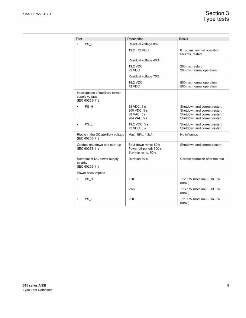
Test Description Result• PS_L Residual voltage 0%:
19.2...72 VDC 0...50 ms, normal operation>50 ms, restart
Residual voltage 40%:
19.2 VDC72 VDC
200 ms, restart200 ms, normal operation
Residual voltage 70%:
19.2 VDC72 VDC
500 ms, normal operation500 ms, normal operation
Interruptions of auxiliary powersupply voltage(IEC 60255-11)
• PS_H 38 VDC, 5 s300 VDC, 5 s38 VAC, 5 s264 VAC, 5 s
Shutdown and correct restartShutdown and correct restartShutdown and correct restartShutdown and correct restart
• PS_L 19.2 VDC, 5 s72 VDC, 5 s
Shutdown and correct restartShutdown and correct restart
Ripple in the DC auxiliary voltage(IEC 60255-11)
Max. 15%, f=2xfn No influence
Gradual shutdown and start-up(IEC 60255-11)
Shut-down ramp: 60 sPower off period: 300 sStart-up ramp: 60 s
Shutdown and correct restart
Reversal of DC power supplypolarity(IEC 60255-11)
Duration 60 s Correct operation after the test
Power consumption
• PS_H VDC ~12.3 W (nominal)/~ 18.0 W(max.)
VAC ~13.5 W (nominal)/~ 19.3 W(max.)
• PS_L VDC ~11.7 W (nominal)/~ 16.9 W(max.)
1MAC057558-TC B Section 3Type tests
615 series ANSI 9Type Test Certificate

Table 6: Contact tests
Contact type Test (IEC 60255-1 and IEEEC37.90-2005)
Requirement
Double-pole power outputs withTCS function
Making capacity:
• Continuous carry 8 A
• Make and carry 3 s 15 A
• Make and carry 0.5 s 30 A
Breaking capacity when L/R ≤40ms, two contacts connected inseries:
• 48 V DC 5 A
• 110 V DC 3 A
• 220 V DC 1 A
Mechanical withstand capability 10 000 operations
Single-pole power outputs Making capacity:
• Continuous carry 8 A
• Make and carry 3 s 15 A
• Make and carry 0.5 s 30 A
Breaking capacity when L/R ≤40ms:
• 48 V DC 5 A
• 110 V DC 3 A
• 220 V DC 1 A
Mechanical withstand capability 10 000 operations
Table continues on next page
Section 3 1MAC057558-TC BType tests
10 615 series ANSIType Test Certificate

Contact type Test (IEC 60255-1 and IEEEC37.90-2005)
Requirement
Signal output X100:S01 Making capacity:
• Continuous carry 5 A
• Make and carry 3 s 15 A
• Make and carry 0.5 s 30 A
Breaking capacity when L/R ≤40ms:
• 48 V DC 1 A
• 110 V DC 0.25 A
• 220 V DC 0.15 A
Mechanical withstand capability 10 000 operations
Signal outputs and IRF output Making capacity:
• Continuous carry 5 A
• Make and carry 3 s 10 A
• Make and carry 0.5 s 15 A
Breaking capacity when L/R ≤40ms:
• 48 V DC 1 A
• 110 V DC 0.25 A
• 220 V DC 0.15 A
Mechanical withstand capability 10 000 operations
Table 7: Electromagnetic compatibility tests
Description Type test value Reference1 MHz/100 kHz burst disturbancetest
IEC 61000-4-18IEC 60255-26, class IIIIEEE C37.90.1-2002
• Common mode 2.5 kV
• Differential mode 2.5 kV
3 MHz, 10 MHz and 30 MHz burstdisturbance test
IEC 61000-4-18IEC 60255-26, class III
Table continues on next page
1MAC057558-TC B Section 3Type tests
615 series ANSI 11Type Test Certificate

Description Type test value Reference• Common mode 2.5 kV
Electrostatic discharge test IEC 61000-4-2IEC 60255-26IEEE C37.90.3-2001
• Contact discharge 8 kV
• Air discharge 15 kV
Radio frequency interference test
10 V (rms)f = 150 kHz...80 MHz
IEC 61000-4-6IEC 60255-26, class III
10 V/m (rms)f = 80...2700 MHz
IEC 61000-4-3IEC 60255-26, class III
10 V/mf = 900 MHz
ENV 50204IEC 60255-26, class III
20 V/m (rms)f = 80...1000 MHz
IEEE C37.90.2-2004
Fast transient disturbance test IEC 61000-4-4IEC 60255-26IEEE C37.90.1-2002
• All ports 4 kV
Surge immunity test IEC 61000-4-5IEC 60255-26
• Communication 1 kV, line-to-ground
• Other ports 4 kV, line-to-ground,2 kV, line-to-line
Power frequency (50 Hz)magnetic field immunity test
IEC 61000-4-8
• Continuous• 1...3 s 300 A/m
1000 A/m
Pulse magnetic field immunity test 1000 A/m6.4/16 µs
IEC 61000-4-9
Damped oscillatory magnetic fieldimmunity test
IEC 61000-4-10
• 2 s 100 A/m
• 1 MHz 400 transients/s
Voltage dips and shortinterruptions
30%/10 ms60%/100 ms60%/1000 ms>95%/5000 ms
IEC 61000-4-11
Table continues on next page
Section 3 1MAC057558-TC BType tests
12 615 series ANSIType Test Certificate

Description Type test value ReferencePower frequency immunity test Binary inputs only IEC 61000-4-16
IEC 60255-26, class A
• Common mode 300 V rms
• Differential mode 150 V rms
Conducted common modedisturbances
15 Hz...150 kHzTest level 3 (10/1/10 V rms)
IEC 61000-4-16
Emission tests EN 55011, class AIEC 60255-26CISPR 11CISPR 12
• Conducted
0.15...0.50 MHz <79 dB (µV) quasi peak<66 dB (µV) average
0.5...30 MHz <73 dB (µV) quasi peak<60 dB (µV) average
• Radiated
30...230 MHz <40 dB (µV/m) quasi peak,measured at 10 m distance
230...1000 MHz <47 dB (µV/m) quasi peak,measured at 10 m distance
1…3 GHz <76 dB (µV/m) peak<56 dB (µV/m) average,measured at 3 m distance
3…6 GHz <80 dB (µV/m) peak<60 dB (µV/m) average,measured at 3 m distance
Table 8: Insulation tests
Description Type test value ReferenceDielectric tests 2 kV, 50 Hz, 1 min
500 V, 50 Hz, 1 min,communication
IEC 60255-27IEEE C37.90-2005
Impulse voltage test 5 kV, 1.2/50 μs, 0.5 J1 kV, 1.2/50 μs, 0.5 J,communication
IEC 60255-27IEEE C37.90-2005
Insulation resistancemeasurements
>100 MΩ, 500 V DC IEC 60255-27
Protective bonding resistance <0.1 Ω, 4 A, 60 s IEC 60255-27
1MAC057558-TC B Section 3Type tests
615 series ANSI 13Type Test Certificate

Table 9: Mechanical tests
Description Requirement ReferenceVibration tests (sinusoidal) Class 2 IEC 60068-2-6 (test Fc)
IEC 60255-21-1
Shock and bump test Class 2 IEC 60068-2-27 (test Ea shock)IEC 60068-2-29 (test Eb bump)IEC 60255-21-2
Seismic test Class 2 IEC 60255-21-3
Mechanical durability • 200 withdrawals andinsertions of the plug-in unit
• 200 adjustments ofprotection relay's settingcontrols
IEEE C37.90-2005
Table 10: Environmental tests
Description Type test value ReferenceDry heat test • 96 h at +55ºC
• 16 h at +85ºC1)2)IEC 60068-2-2IEEE C37.90-2005
Dry cold test • 96 h at -25ºC• 16 h at -40ºC
IEC 60068-2-1IEEE C37.90-2005
Damp heat test • 6 cycles (12 h + 12 h) at+25°C…+55°C, humidity>93%
IEC 60068-2-30
• +55°C, Rh = 95%, 96h IEEE C37.90-2005
Change of temperature test • 5 cycles (3 h + 3 h)at -25°C...+55°C
IEC60068-2-14
Storage test • 96 h at -40ºC• 96 h at +85ºC
IEC 60068-2-1IEC 60068-2-2IEEE C37.90-2005
1) For relays with an LC communication interface the maximum operating temperature is +70oC2) For RED615 +70oC, 16 h
Section 3 1MAC057558-TC BType tests
14 615 series ANSIType Test Certificate

15

ABB Distribution SolutionsDistribution AutomationP.O. Box 699FI-65101 VAASA, FinlandPhone +358 10 22 11
ABB Inc.655 Century PointLake Mary, FL 32746, USAPhone +1-800-222 1946
www.abb.com/mediumvoltagewww.abb.com/relionwww.abb.com/substationautomation
—
© Copyright 2019 ABB. All rights reserved. 1MA
C0
5755
8-T
C B