type n connectors - docs-emea.rs-online.com · straight crimp type plug – solder or crimp contact...
TRANSCRIPT

Connectivity....forBusiness-Critical Continuity
Type N ConnectorsProduct Catalog

2
Connectivity....for
Business-Critical ContinuityType N Connectors
Johnson® Type N Connectors meet or exceed the performance requirements of MIL-PRF-39012. Alldesigns are based on 50 ohm system impedance per MIL-STD-348, and operate at frequencies up to11 GHz minimum.
Applications
Features
• All contacts are plated with 50 micro-inches of Gold for excellent durability and high frequency performance
• Brass bodies are offered with Tri-alloy plating as the standard finish, and Gold where soldering is required
• Coupling nuts are hex shaped to allow the connectors to be tightened to specified mating torque• Plug interfaces and bulkhead jack bodies include gaskets for environmental sealing• Precision grade in-series adapters have very low return loss performance to 18 GHz• Cabled contacts are captivated upon assembly• Flexible cable contacts can be crimped or soldered• Semi-rigid cabled connectors are capable of operation to 18 GHz• Semi-rigid cabled plug connectors are available in one piece versions, requiring solder
attachment only between the cable jacket and connector body
• Antennas• Base stations• Broadcast• Cable assemblies • Cellular• Instrumentation• Microwave Radio
• PCS• Radar• Radios• RF and Microwave Components• Satcom• Surge Protection • WLAN
Table of ContentsPAGE
ASSEMBLY INSTRUCTIONS . . . . . . . . . . . . . . . . . . . . . . . . .13ASSEMBLY TOOLS . . . . . . . . . . . . . . . . . . . . . . . . . . . . . . . .11COMPETITOR CROSS REFERENCE . . . . . . . . . . . . . . . . . . .23ELECTRICAL SPECIFICATIONS . . . . . . . . . . . . . . . . . . . . . .3-4ENVIRONMENTAL SPECIFICATIONS . . . . . . . . . . . . . . . . . . .5FLEXIBLE CABLE CONNECTORS . . . . . . . . . . . . . . . . . . . . . .8IN-SERIES ADAPTERS . . . . . . . . . . . . . . . . . . . . . . . . . . . . . .10JACK RECEPTACLES . . . . . . . . . . . . . . . . . . . . . . . . . . . . . . . . .9MATERIAL SPECIFICATIONS . . . . . . . . . . . . . . . . . . . . . . . . .5MECHANICAL SPECIFICATIONS . . . . . . . . . . . . . . . . . . . . . .5MOUNTING HOLES . . . . . . . . . . . . . . . . . . . . . . . . . . . . . . . .6SEMI-RIGID CABLED CONNECTORS . . . . . . . . . . . . . . . . . .7

3
Connectivity....for
Business-Critical Continuity Type N Connectors
ELECTRICAL SPECIFICATIONSImpedance: 50 Ohms
Frequency Range:
Flexible Cabled and Receptacles . . . . . . . . . . . . . . . . . . . . . . . . . . . . . . . . . . . . . . . . . . . . . . . . . . . . . . . . . . . . . . . . . . . . . 0-11 GHzSemi-Rigid Cabled and Adapters . . . . . . . . . . . . . . . . . . . . . . . . . . . . . . . . . . . . . . . . . . . . . . . . . . . . . . . . . . . . . . . . . . . . 0-18 GHz
VSWR: (f = GHz)0-11 GHz
Straight Flexible Cabled . . . . . . . . . . . . . . . . . . . . . . . . . . . . . . . . . . . . . . . . . . . . . . . . . . . . . . . . . . . . . . . . . . . . . . . . . . . . 1.30 Max
0-9 GHz 9-11 GHzRight Angle Flexible Cabled. . . . . . . . . . . . . . . . . . . . . . . . . . . . . . . . . . . . . . . . . . . . . . . . . . . . . . . 1.35 MAX 1.50 Max
0-11 GHz 11-18 GHzRG-405 Semi-Rigid Plugs . . . . . . . . . . . . . . . . . . . . . . . . . . . . . . . . . . . . . . . . . . . . . . . . . . . . . . . . . 1.07+.01f <1.25 TypicalRG-402 Semi-Rigid Plugs . . . . . . . . . . . . . . . . . . . . . . . . . . . . . . . . . . . . . . . . . . . . . . . . . . . . . . . . . 1.05+.01f <1.25 TypicalRG-401 Semi-Rigid Plugs . . . . . . . . . . . . . . . . . . . . . . . . . . . . . . . . . . . . . . . . . . . . . . . . . . . . . . . . . 1.06+.01f <1.25 TypicalRG-405 Semi-Rigid Jacks . . . . . . . . . . . . . . . . . . . . . . . . . . . . . . . . . . . . . . . . . . . . . . . . . . . . . . . . . 1.15+.02f <1.50 TypicalRG-402 Semi-Rigid Jacks . . . . . . . . . . . . . . . . . . . . . . . . . . . . . . . . . . . . . . . . . . . . . . . . . . . . . . . . . 1.10+.02f <1.50 TypicalRG-401 Semi-Rigid Jacks . . . . . . . . . . . . . . . . . . . . . . . . . . . . . . . . . . . . . . . . . . . . . . . . . . . . . . . . . 1.10+.02f <1.50 Typical
0-18 GHzAdapters . . . . . . . . . . . . . . . . . . . . . . . . . . . . . . . . . . . . . . . . . . . . . . . . . . . . . . . . . . . . . . . . . . . . . . . . . . . . . . . . . . . . . . . . . 1.05+.01f
Un-cabled Receptacles . . . . . . . . . . . . . . . . . . . . . . . . . . . . . . . . . . . . . . . . . . . . . . . . . . . . . . . . . . . . . . . . . . . . . . . . . . . . . . . . . . N/A
Insertion Loss: (dB, tested at 9 GHz)
Straight Flexible Cabled . . . . . . . . . . . . . . . . . . . . . . . . . . . . . . . . . . . . . . . . . . . . . . . . . . . . . . . . . . . . . . . . . . . . . . . . . . . . 0.15 MaxRight Angle Flexible Cabled . . . . . . . . . . . . . . . . . . . . . . . . . . . . . . . . . . . . . . . . . . . . . . . . . . . . . . . . . . . . . . . . . . . . . . . . 0.30 MaxSemi-Rigid Cabled and Adapters . . . . . . . . . . . . . . . . . . . . . . . . . . . . . . . . . . . . . . . . . . . . . . . . . . . . . . . . . . . . . . . . 0.05 f (GHz)Un-cabled Receptacles . . . . . . . . . . . . . . . . . . . . . . . . . . . . . . . . . . . . . . . . . . . . . . . . . . . . . . . . . . . . . . . . . . . . . . . . . . . . . . . . . . N/A
Working Voltage: (Vrms maximum)Sea Level 70K Feet
RG-316, 316DS Cabled . . . . . . . . . . . . . . . . . . . . . . . . . . . . . . . . . . . . . . . . . . . . . . . . . . . . . . . . . . . . 250 65RG-58, 142, 405 Cabled . . . . . . . . . . . . . . . . . . . . . . . . . . . . . . . . . . . . . . . . . . . . . . . . . . . . . . . . . . . 335 85RG-402 Cabled. . . . . . . . . . . . . . . . . . . . . . . . . . . . . . . . . . . . . . . . . . . . . . . . . . . . . . . . . . . . . . . . . . . . 500 125RG-213, 214, 401, LMR-400 Cabled . . . . . . . . . . . . . . . . . . . . . . . . . . . . . . . . . . . . . . . . . . . . . . . . . 1000 250Un-cabled Receptacles and Adapters . . . . . . . . . . . . . . . . . . . . . . . . . . . . . . . . . . . . . . . . . . . . . . . . 1000 250
Dielectric Withstanding Voltage: (Vrms minimum) Sea Level
RG-316, 316DS Cabled . . . . . . . . . . . . . . . . . . . . . . . . . . . . . . . . . . . . . . . . . . . . . . . . . . . . . . . . . . . . . . . . . . . . . . . . . . . . . . . . . 750RG-58, 142, 405 Cabled . . . . . . . . . . . . . . . . . . . . . . . . . . . . . . . . . . . . . . . . . . . . . . . . . . . . . . . . . . . . . . . . . . . . . . . . . . . . . . . 1000RG-402 Cabled . . . . . . . . . . . . . . . . . . . . . . . . . . . . . . . . . . . . . . . . . . . . . . . . . . . . . . . . . . . . . . . . . . . . . . . . . . . . . . . . . . . . . . . 1500RG-213, 214, 401, LMR-400 Cabled . . . . . . . . . . . . . . . . . . . . . . . . . . . . . . . . . . . . . . . . . . . . . . . . . . . . . . . . . . . . . . . . . . . . . 2500Un-cabled Receptacles and Adapters . . . . . . . . . . . . . . . . . . . . . . . . . . . . . . . . . . . . . . . . . . . . . . . . . . . . . . . . . . . . . . . . . . . . 2500
Corona Level: (Volts minimum) 70K Feet
RG-316, 316DS Cabled . . . . . . . . . . . . . . . . . . . . . . . . . . . . . . . . . . . . . . . . . . . . . . . . . . . . . . . . . . . . . . . . . . . . . . . . . . . . . . . . . 190RG-58, 142, 405 Cabled . . . . . . . . . . . . . . . . . . . . . . . . . . . . . . . . . . . . . . . . . . . . . . . . . . . . . . . . . . . . . . . . . . . . . . . . . . . . . . . . 250RG-402 Cabled . . . . . . . . . . . . . . . . . . . . . . . . . . . . . . . . . . . . . . . . . . . . . . . . . . . . . . . . . . . . . . . . . . . . . . . . . . . . . . . . . . . . . . . . 375RG-213, 214, 401, LMR-400 Cabled and Adapters . . . . . . . . . . . . . . . . . . . . . . . . . . . . . . . . . . . . . . . . . . . . . . . . . . . . . . . . . 500Un-cabled Receptacles . . . . . . . . . . . . . . . . . . . . . . . . . . . . . . . . . . . . . . . . . . . . . . . . . . . . . . . . . . . . . . . . . . . . . . . . . . . . . . . . . N/A

4
Connectivity....for
Business-Critical ContinuityType N Connectors
ELECTRICAL SPECIFICATIONS cont’dRF High Potential Withstanding Voltage: (Vrms minimum, tested at 4 and 7 MHz)
RG-316, 316DS Cabled . . . . . . . . . . . . . . . . . . . . . . . . . . . . . . . . . . . . . . . . . . . . . . . . . . . . . . . . . . . . . . . . . . . . . . . . . . . . . . . . . 500RG-58, 142, 405 Cabled . . . . . . . . . . . . . . . . . . . . . . . . . . . . . . . . . . . . . . . . . . . . . . . . . . . . . . . . . . . . . . . . . . . . . . . . . . . . . . . . 670RG-402 Cabled . . . . . . . . . . . . . . . . . . . . . . . . . . . . . . . . . . . . . . . . . . . . . . . . . . . . . . . . . . . . . . . . . . . . . . . . . . . . . . . . . . . . . . . . 1000RG-213, 214, 401, LMR-400 Cabled . . . . . . . . . . . . . . . . . . . . . . . . . . . . . . . . . . . . . . . . . . . . . . . . . . . . . . . . . . . . . . . . . . . . . 1500Un-cabled Receptacles and Adapters . . . . . . . . . . . . . . . . . . . . . . . . . . . . . . . . . . . . . . . . . . . . . . . . . . . . . . . . . . . . . . . . . . . . 1500
Insulation Resistance: 5000 Megohms minimum
Contact Resistance: (milliohms maximum)Initial After Environmental
Center Contact Straight Cabled (non-captivated) . . . . . . . . . . . . . . . . . . . . . . . . . . . . . . . . . . . . . . . . . . 1.0 1.5Straight Cabled (captivated) . . . . . . . . . . . . . . . . . . . . . . . . . . . . . . . . . . . . . . . . . . . . . . . 2.5 3.0Right Angle Cabled . . . . . . . . . . . . . . . . . . . . . . . . . . . . . . . . . . . . . . . . . . . . . . . . . . . . . . 2.5 3.0Un-cabled Receptacles and Adapters . . . . . . . . . . . . . . . . . . . . . . . . . . . . . . . . . . . . . . . 1.0 1.5
Outer Contact . . . . . . . . . . . . . . . . . . . . . . . . . . . . . . . . . . . . . . . . . . . . . . . . . . . . . . . . . . . . . 0.2 N/ABraid to Body (Flexible Cabled Only) . . . . . . . . . . . . . . . . . . . . . . . . . . . . . . . . . . . . . . . . . . 0.05 N/A
RF Leakage: (dB minimum, tested at 2.5 GHz)
Cabled Connectors and Adapters . . . . . . . . . . . . . . . . . . . . . . . . . . . . . . . . . . . . . . . . . . . . . . . . . . . . . . . . . . . . . . . . . . . . . . . . . -90Un-cabled Receptacles . . . . . . . . . . . . . . . . . . . . . . . . . . . . . . . . . . . . . . . . . . . . . . . . . . . . . . . . . . . . . . . . . . . . . . . . . . . . . . . . . . N/A
IMP3: Typically <-90 dBm (tested per IEC Guidelines using 20W inputs swept over 1930-1990 MHz)
Type N In-Series Adapter Return Loss
-60
-50
-40
-30
-20
-10
0 3 6 9 12 15 18
Frequency (GHz)
S11
(dB
)
138-4901-807 138-4901-817 VSWR = 1.05+.01F

Connectivity....for
Business-Critical Continuity Type N Connectors
5
MECHANICAL SPECIFICATIONSEngagement Design: MIL-STD-348A, Series NDurability: 500 Cycles minimumEngagement/Disengagement Force: 6 inch-pounds maximumMating Torque: 7 to 10 inch-poundsBulkhead Mounting Nut Torque: 15 inch-pounds recommendedCoupling Proof Torque: 15 inch-pounds minimumCoupling Nut Retention: 100 pounds minimumContact Retention: (minimum - captivated contacts only)
Axial Force (lbs) Torque (in-oz)Cabled Connectors and Adapters . . . . . . . . . . . . . . . . . . . . . . . . . . . . . . . . . . . . . . . . . . . . . . . . . . . . . . . 6 N/AUn-cabled Receptacles . . . . . . . . . . . . . . . . . . . . . . . . . . . . . . . . . . . . . . . . . . . . . . . . . . . . . . . . . . . . . . . . 6 4
Cable Retention: (minimum*)Axial Force (lbs) Torque (in-oz)
RG-316 Cabled . . . . . . . . . . . . . . . . . . . . . . . . . . . . . . . . . . . . . . . . . . . . . . . . . . . . . . . . . . . . . . . . . . . . . . . 20 N/ARG-316DS Cabled . . . . . . . . . . . . . . . . . . . . . . . . . . . . . . . . . . . . . . . . . . . . . . . . . . . . . . . . . . . . . . . . . . . . . 30 N/ARG-58 Cabled . . . . . . . . . . . . . . . . . . . . . . . . . . . . . . . . . . . . . . . . . . . . . . . . . . . . . . . . . . . . . . . . . . . . . . . . 40 N/ARG-142 Cabled . . . . . . . . . . . . . . . . . . . . . . . . . . . . . . . . . . . . . . . . . . . . . . . . . . . . . . . . . . . . . . . . . . . . . . . 45 N/ARG-213, 214 and LMR-400 Cabled . . . . . . . . . . . . . . . . . . . . . . . . . . . . . . . . . . . . . . . . . . . . . . . . . . . . . . . 90 N/ARG-405 Cabled . . . . . . . . . . . . . . . . . . . . . . . . . . . . . . . . . . . . . . . . . . . . . . . . . . . . . . . . . . . . . . . . . . . . . . . 30 16RG-402 Cabled . . . . . . . . . . . . . . . . . . . . . . . . . . . . . . . . . . . . . . . . . . . . . . . . . . . . . . . . . . . . . . . . . . . . . . . . 60 55RG-401 Cabled . . . . . . . . . . . . . . . . . . . . . . . . . . . . . . . . . . . . . . . . . . . . . . . . . . . . . . . . . . . . . . . . . . . . . . . 90 80
* Or cable breaking strength, whichever is less
ENVIRONMENTAL SPECIFICATIONS(Meets or Exceeds the Applicable Paragraph of MIL-PRF-39012)
Temperature Range: -65°C to +165°CThermal Shock: MIL-STD-202, Method 107, Condition B (except +85°C high temperature)Corrosion: MIL-STD-202, Method 101, Condition BShock: MIL-STD-202, Method 213, Condition IVibration: MIL-STD-202, Method 204, Condition BMoisture Resistance: MIL-STD-202, Method 106
MATERIAL SPECIFICATIONSBodies: Crimp - Brass per ASTM B16, Tri-Alloy (Cu/Sn/Zn) plated (.0001” min)
Solder - Brass per ASTM B16, Gold plated* per MIL-G-45204 (.00001” min)Adapter - Brass per ASTM B16, Tri-Alloy (Cu/Sn/Zn) or Nickel per QQ-N-290 plated (.0001” min)
Contacts: Male - Brass per ASTM B16, Gold plated* per MIL-G-45204 (.00005” min)Female – Beryllium Copper per ASTM B196, Gold plated* per MIL-G-45204 (.00005” min)Adapter – Beryllium Copper per ASTM B196, Gold plated* per MIL-G-45204 (.00005” min)
Insulators: PTFE Fluorocarbon per ASTM D1710 and ASTM D1457Gaskets: Silicon Rubber per ZZ-R-765Crimp Sleeves: Copper per ASTM A75, Tri-Alloy (Cu/Sn/Zn) plated (.0001” min)End Caps: Brass per ASTM B16, Tri-Alloy (Cu/Sn/Zn) plated (.0001” min)Nut Retention Spring (Plugs): Beryllium Copper per ASTM B196, un-platedMounting Nut (Bulkhead Jacks): Brass per ASTM B16, Nickel plated per QQ-N-290 (.0001” min)Lock Washer (Bulkhead Jacks): Steel, Zinc plated (.0001” min)
* All Gold plated parts include a .00005” minimum Nickel under plated barrier layer

6
Connectivity....for
Business-Critical ContinuityType N Connectors
MATING ENGAGEMENT FOR TYPE N SERIES PER MIL-STD-348A
MOUNTING HOLES
Fig 1 Fig 2

7
Connectivity....for
Business-Critical Continuity Type N Connectors
Straight Solder Type Plug – With Solder Contact
Cable Type VSWR & Freq. Range Gold PlatedRG-405, .086 Semi-Rigid 1.07+.01f (GHz), 0-11 GHz <1.25 Typical, 11-18 GHz 138-4693-001*RG-402, .141 Semi-Rigid 1.05+.01f (GHz), 0-11 GHz <1.25 Typical, 11-18 GHz 138-4694-001*RG-401, .250 Semi-Rigid 1.06+.01f (GHz), 0-11 GHz <1.25 Typical, 11-18 GHz 138-4696-001*
* Tri-Alloy plated coupling nut
Straight Solder Type Plug – Captivated Solderless Contact
Cable Type VSWR & Freq. Range Gold PlatedRG-405, .086 Semi-Rigid 1.07+.01f (GHz), 0-11 GHz <1.25 Typical, 11-18 GHz 138-4693-011*RG-402, .141 Semi-Rigid 1.05+.01f (GHz), 0-11 GHz <1.25 Typical, 11-18 GHz 138-4694-011*RG-401, .250 Semi-Rigid 1.06+.01f (GHz), 0-11 GHz <1.25 Typical, 11-18 GHz 138-4696-011*
* Tri-Alloy plated coupling nut
Straight Solder Type Bulkhead Jack – With Solder Contact
Cable Type VSWR & Freq. Range Gold PlatedRG-405, .086 Semi-Rigid 1.15+.02f (GHz), 0-11 GHz <1.50 Typical, 11-18 GHz 138-4593-401*RG-402, .141 Semi-Rigid 1.10+.02f (GHz), 0-11 GHz <1.50 Typical, 11-18 GHz 138-4594-401*RG-401, .250 Semi-Rigid 1.10+.02f (GHz), 0-11 GHz <1.50 Typical, 11-18 GHz 138-4596-401*
* Tri-Alloy plated bulkhead jack bodyMounting hole layout figure 1 on page 6

Straight Crimp Type Plug – Solder or Crimp Contact
Cable Type VSWR & Freq. Range Tri-Alloy Plated FigureRG-161/U, 174, 188, 316 1.30 Max, 0-11 GHz 138-4403-007 1RG-188 DS, RG-316 DS 1.30 Max, 0-11 GHz 138-4404-007 1RG-58/U, 141, 303 1.30 Max, 0-11 GHz 138-4407-007 2RG-55/U, 142, 223, 400 1.30 Max, 0-11 GHz 138-4408-007 2RG-8/U, 213 1.30 Max, 0-11 GHz 138-4416-007 3RG-9/U, 214 1.30 Max, 0-11 GHz 138-4418-007 3LMR-400, BELDEN 9913 1.30 Max, 0-11 GHz 138-4449-007 3
Right Angle Crimp Type Plug – Captivated Contact
Cable Type VSWR & Freq. Range Tri-Alloy Plated FIigure “A” “B”RG-161/U, 174, 188, 316 1.35 Max, 0-9 GHz 1.50 Max, 9-11 GHz 138-4403-107 1 1.227 (31.17) .977 (24.82)RG-188 DS, RG-316 DS 1.35 Max, 0-9 GHz 1.50 Max, 9-11 GHz 138-4404-107 1 1.227 (31.17) .977 (24.82)RG-58/U, 141, 303 1.35 Max, 0-9 GHz 1.50 Max, 9-11 GHz 138-4407-107 2 1.253 (31.83) 1.003 (25.48)RG-55/U, 142, 223, 400 1.35 Max, 0-9 GHz 1.50 Max, 9-11 GHz 138-4408-107 2 1.253 (31.83) 1.003 (25.48)RG-8/U, 213 1.35 Max, 0-9 GHz 1.50 Max, 9-11 GHz 138-4416-107 2 1.365 (34.67) 1.115 (28.32)RG-9/U, 214 1.35 Max, 0-9 GHz 1.50 Max, 9-11 GHz 138-4418-107 2 1.365 (34.67) 1.115 (28.32)
Straight Crimp Type Bulkhead Jack – Solder or Crimp Contact
Cable Type VSWR & Freq. Range Tri-Alloy Plated “A”RG-161/U, 174, 188, 316 1.30 Max, 0-11 GHz 138-4303-407 .943 (23.95)RG-188 DS, RG-316 DS 1.30 Max, 0-11 GHz 138-4304-407 .943 (23.95)RG-58/U, 141, 303 1.30 Max, 0-11 GHz 138-4307-407 .943 (23.95)RG-55/U, 142, 223, 400 1.30 Max, 0-11 GHz 138-4308-407 .943 (23.95)RG-8/U, 213 1.30 Max, 0-11 GHz 138-4316-407 .997 (25.32)RG-9/U, 214 1.30 Max, 0-11 GHz 138-4318-407 .997 (25.32)LMR-400, BELDEN 9913 1.30 Max, 0-11 GHz 138-4349-407 .997 (25.32)
Mounting hole layout figure 1 on page 6
8
Connectivity....for
Business-Critical ContinuityType N Connectors
Fig 1 Fig 2 Fig 3
Fig 1 Fig 2

Rear Mount Bulkhead Jack Receptacle
Freq. Range Tri-Alloy Plated0-11 GHz 138-4701-407
Mounting hole layout figure 1 on page 6
4-Hole Flange Mount Jack Receptacle – Flush Dielectric
Freq. Range Tri-Alloy Plated0-11 GHz 138-4701-607
Mounting hole layout figure 2 on page 6
9
Connectivity....for
Business-Critical Continuity Type N Connectors

10
Connectivity....for
Business-Critical ContinuityType N Connectors
Jack to Jack Adapter
VSWR & Freq. Range Tri-Alloy Plated1.05+.01f (GHz), 0-18 GHz 138-4901-807
Jack to Bulkhead Jack Adapter
VSWR & Freq. Range Tri-Alloy Plated1.05+.01f (GHz), 0-18 GHz 138-4901-407
Mounting hole layout figure 1 on page 6
Plug to Plug Adapter
VSWR & Freq. Range Tri-Alloy Plated1.05+.01f (GHz), 0-18 GHz 138-4901-817

11
Connectivity....for
Business-Critical Continuity Type N Connectors
Precision Ergonomic Hand Crimp ToolHand crimp tool and die sets include all hex sizes necessary for Type Nconnector applications. Ratchet tool action insures a complete crimp every time.
Part No. Description Hex Width140-0000-967 Erognomic Hand Crimp Tool Frame Only
• Longer handles for leverage• Padded and contoured to fit in hand• Precision ground die sets• 50,000 cycle lifespan frame
140-0000-990 Die set for RG-316, 316 DS, 58, 142 .068 (1.73) .090 (2.29).128 (3.25) .475 (12.07).151 (3.83) .475 (12.07).213 (5.41) .475 (12.07)
140-0000-991 Die set for RG-213, 214, LMR-4000 .111 (2.82) .090 (2.29).116 (2.95) .090 (2.29).429 (10.90) .475 (12.07)
Contact Hand Crimp ToolThe micro contact crimp tool provides an accurate eight indent crimp on smalldiameter contacts. This crimp tool is used with the 140-0000-971 VariablePositioner. Set the crimp size in the adjustment window and position thevariable locator to obtain an accurate repeatable crimp on the contact.
Part No. Description ASTRO Tool Part No.140-0000-970 Frame Only 612118-1140-0000-971 Positioner N/A
ASSEMBLY TOOLS

12
Connectivity....for
Business-Critical ContinuityType N Connectors
Item Part No. DescriptionA 140-0000-962 Soldering Vise (does not include inserts (B) or stop screws (F) ,(G))B 140-0000-964 Semi-Rigid Cable Clamp Inserts for .086" OD Cable
140-0000-965 Semi-Rigid Cable Clamp Inserts for .141" OD Cable140-0000-986 Semi-Rigid Cable Clamp Inserts for .250" OD Cable
C 140-0000-983 Location Fixture for Type N Plug ConnectorsD 140-0000-984 Solder Shim for .086" & .141”OD Cable
140-0000-985 Solder Shim for .250" OD CableE 140-0000-987 Location Fixture for .086" OD Cable
140-0000-988 Location Fixture for .141" OD Cable140-0000-989 Location Fixture for .250" OD Cable
F 140-0000-981 Stop Screw for Semi-Rigid Type N PlugsG 140-0000-972 Stop Screw for Semi-Rigid Type N Jacks
Semi-Rigid Assembly ToolsAccurate assembly of the Semi-Rigid Cabled Connectors is obtained with the tools listed below. Industry standard devices are used if possiblefor customer convenience and tool compatibility.
A.B.
C.
D.
E.
F. G.

13
Connectivity....for
Business-Critical Continuity Type N Connectors
ASSEMBLY INSTRUCTIONS
Cable Group Part No. Crimp Sleeve Hex Size Contact CrimpRG-316/U, 161, 174, 188 138-4403-007 .128 (3.25) 8 INDENTRG-316 DS, 188 DS 138-4404-007 .151 (3.84) 8 INDENT
AssemblyTool 138-4403/4404-007Crimp Frame 140-0000-967Die Set 140-0000-990Contact Tool 140-0000-970Positioner 140-0000-971
Type N Straight Plug Crimp Style for RG-316 and 316DS Flexible Cable
1 Identify connector parts (3 piece parts).2. Strip cable to dimensions shown. Do not nick center conductor.
A wire stripper of correct size is recommended for this step. Tincenter conductor if contact will be solder attached. Do not tincenter conductor if contact will be crimp attached. Slide crimpsleeve onto jacket of cable.
3. Assemble rear contact onto cable as shown Rear contactshould butt against cable dielectric during attachment.Solder Attachment: Solder rear contact to center conductorthrough solder hole using .020 (.051) diameter flux core solderwire. Use a minimum amount of solder for a good joint.Crimp Attachment: Crimp rear contact to center conductorusing Johnson indent hand tool 140-0000-970. Crimp locationshould be centered between end of rear contact and solder holeusing positioning tool 140-0000-971. Crimp attachment to solidcenter conductor cables is not recommended.
4. Flare braid and slide plug connector assembly over rear contactand under braid. Rear contact must engage fully with internalcaptivated plug contact. Cable jacket should be located nearend of crimp stem when contacts are fully engaged.
5. Arrange braid uniformly around crimp stem. Slide crimp sleeveforward and crimp using Johnson ergonomic hand crimp frame 140-0000-967 with recommended hex size die set. Maintainforward pressure on cable while crimping.
14
Connectivity....for
Business-Critical ContinuityType N Connectors
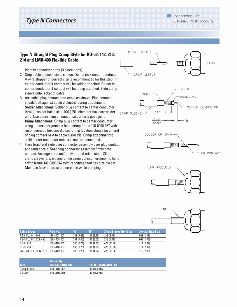
Type N Straight Plug Crimp Style for RG-58, 142, 213,214 and LMR-400 Flexible Cable
1. Identify connector parts (3 piece parts).2. Strip cable to dimensions shown. Do not nick center conductor.
A wire stripper of correct size is recommended for this step. Tincenter conductor if contact will be solder attached. Do not tincenter conductor if contact will be crimp attached. Slide crimpsleeve onto jacket of cable.
3. Assemble plug contact onto cable as shown. Plug contactshould butt against cable dielectric during attachment.Solder Attachment: Solder plug contact to center conductorthrough solder hole using .020 (.051) diameter flux core solderwire. Use a minimum amount of solder for a good joint.Crimp Attachment: Crimp plug contact to center conductorusing Johnson ergonomic hand crimp frame 140-0000-967 withrecommended hex size die set. Crimp location should be on endof plug contact next to cable dielectric. Crimp attachment tosolid center conductor cables is not recommended.
4. Flare braid and slide plug connector assembly over plug contactand under braid. Seat plug connector assembly firmly ontocontact. Arrange braid uniformly around crimp stem. Slidecrimp sleeve forward and crimp using Johnson ergonomic handcrimp frame 140-0000-967 with recommended hex size die set.Maintain forward pressure on cable while crimping.
Cable Group Part No. “A” “B” Crimp Sleeve Hex Size Contact Hex SizeRG-58/U, 141, 303 138-4407-007 .301 (7.65) .140 (3.56) .213 (5.41) .068 (1.73)RG-55/U, 142, 223, 400 138-4408-007 .301 (7.65) .140 (3.56) .213 (5.41) .068 (1.73)RG-8, 213 138-4416-007 .385 (9.78) .170 (4.32) .429 (10.90) .111 (2.82)RG-9, 214 138-4418-007 .385 (9.78) .170 (4.32) .429 (10.90) .111 (2.82)LMR-400, BELDEN 9913 138-4449-007 .385 (9.78) .170 (4.32) .429 (10.90) .116 (2.95)
AssemblyTool 138-4407/4408-007 138-4416/4418/4449-007Crimp Frame 140-0000-967 140-0000-967Die Set 140-0000-990 140-0000-991

15
Connectivity....for
Business-Critical Continuity Type N Connectors
Type N Right Angle Plug Crimp Style for RG-316,316DS, 58, and 142 Flexible Cable
1. Identify connector parts (3 piece parts).2. Strip cable to dimensions shown. Do not nick center conductor.
A wire stripper of correct size is recommended for this step.Twist stranded center conductor into tight bundle and tin(optional). Slide crimp sleeve onto jacket of cable.
3. Flare braid and slide plug connector assembly over cabledielectric and under braid. Make sure cable dielectric bottomsagainst plug contact as shown. Solder center conductor tocontact through rear access port. Use a minimum amount ofsolder for a full fillet joint.
4. Arrange braid uniformly around crimp stem. Slide crimp sleeveforward and crimp using Johnson ergonomic hand crimp frame140-0000-967 with recommended hex size die set. Screw endcap into access port.
Cable Group Part No. “A” Crimp Sleeve Hex SizeRG-316/U, 161, 174, 188 138-4403-107 .755 (19.18) .128 (3.25)RG-316 DS, 188 DS 138-4404-107 .755 (19.18) .151 (3.84)RG-58/U, 141, 303 138-4407-107 .788 (20.02) .213 (5.41)RG-55/U, 142, 223, 400 138-4408-107 .788 (20.02) .213 (5.41)
AssemblyTool 138-4403/4404/4407/4408-107Crimp Frame 140-0000-967Die Set 140-0000-990

16
Connectivity....for
Business-Critical ContinuityType N Connectors
Type N Right Angle Plug Crimp Style for RG-213 and214 Flexible Cable
1. Identify connector parts (3 piece parts).2. Strip cable to dimensions shown. Do not nick center
conductor. A wire stripper of correct size is recommendedfor this step. Slide crimp sleeve onto jacket of cable.
3. Flare braid and slide plug connector assembly over cabledielectric and under braid. Make sure center conductor iscontained within plug contact as shown. Center conductorshould not protrude above slots in plug contact and cabledielectric should not touch plug contact. Solder centerconductor to plug contact through rear access port. Use aminimum amount of solder for a full fillet joint.
4. Arrange braid uniformly around crimp stem. Slide crimpsleeve forward and crimp using Johnson ergonomic handcrimp frame 140-0000-967 with recommended hex size dieset. Screw end cap into access port.
Cable Group Part No. Crimp Sleeve Hex SizeRG-8, 213 138-4416-107 .429 (10.90)RG-9, 214 138-4418-107 .429 (10.90)
AssemblyTool 138-4416/4418-107Crimp Frame 140-0000-967Die Set 140-0000-991

17
Connectivity....for
Business-Critical Continuity Type N Connectors
Type N Straight Plug Solder Style for Semi-Rigid Cable
1. Identify connector parts (2 piece parts) and tools (5 piece parts).2. Strip cable jacket and dielectric to dimension shown. Do not nick
center conductor. Clean all debris from cable.3. Place plug contact onto center conductor, insert appropriate sized
solder shim between cable jacket and contact.4. Insert contact into location fixture and clamp cable in vise. Tighten
stop screw until light pressure is applied between contact, soldershim and cable jacket.
5. Solder contact to center conductor through solder hole using .020(.051) diameter flux core solder wire. Use a minimum amount ofsolder for a good joint.
6. After solder joint has cooled, loosen stop screw and remove soldershim. Remove cable from vise and remove any excess solder fromcontact with a sharp blade and clean all debris from contact andcable.
7. Insert contact and cable into plug connector assembly, makingsure cable jacket bottoms out against internal shoulder ofconnector assembly. Insert location fixture into connectorassembly and clamp cable in vise. Tighten stop screw until lightpressure is applied between connector assembly and cable jacket.
8. Solder connector body to cable jacket, using a minimum amount ofsolder for a full fillet joint. Allow assembly to cool before removingconnector from vise.
Cable Group Part No. “A”RG-405, .086 Semi-Rigid 138-4693-001 .085 (2.16)RG-402, .141 Semi-Rigid 138-4694-001 .085 (2.16)RG-401, .250 Semi-Rigid 138-4696-001 .100 (2.54)
AssemblyTool 138-4693-001 138-4694-001 138-4696-001Solder Shim 140-0000-984 140-0000-984 140-0000-985Location Fixture 140-0000-983 140-0000-983 140-0000-983Cable Vise 140-0000-962 140-0000-962 140-0000-962Clamp Inserts 140-0000-964 140-0000-965 140-0000-986Stop Screw 140-0000-981 140-0000-981 140-0000-981

18
Connectivity....for
Business-Critical ContinuityType N Connectors
Type N Straight Plug One Piece Style for Semi-Rigid Cable
1. Identify connector and tools (4 piece parts).2. Strip cable jacket and dielectric to dimension shown. Do not nick
center conductor.3. Bevel end of cable center conductor per appropriate dimensional
profile.4. Clean all debris from prepared cable and insert cable into connector
assembly, making sure cable jacket bottoms out against internalshoulder of connector assembly and center conductor engages withinternal captivated plug contact.
5. Insert location fixture into connector assembly and clamp cable invise. Tighten stop screw until light pressure is applied betweenconnector assembly and cable jacket.
6. Solder connector body to cable jacket, using a minimum amount ofsolder for a full fillet joint. Allow assembly to cool before removingconnector from vise.
Cable Group Part No. “A” “B”RG-405, .086 Semi-Rigid 138-4693-011 .085 (2.16) .014 (0.36)RG-402, .141 Semi-Rigid 138-4694-011 .085 (2.16) .022 (0.56)RG-401, .250 Semi-Rigid 138-4696-011 .150 (3.81) .045 (1.14)
AssemblyTool 138-4693-011 138-4694-011 138-4696-011Location Fixture 140-0000-983 140-0000-983 140-0000-983Cable Vise 140-0000-962 140-0000-962 140-0000-962Clamp Inserts 140-0000-964 140-0000-965 140-0000-986Stop Screw 140-0000-981 140-0000-981 140-0000-981

19
Connectivity....for
Business-Critical Continuity Type N Connectors
Type N Bulkhead Jack Crimp Style for RG-316 and316DS Flexible Cable
1. Identify connector parts (6 piece parts).2. Strip cable to dimensions shown. Do not nick center
conductor. A wire stripper of correct size is recommendedfor this step. Tin center conductor if contact will be solderattached. Do not tin center conductor if contact will be crimpattached. Slide crimp sleeve onto jacket of cable.
3. Assemble rear contact onto cable as shown. Rear contactshould butt against cable dielectric during attachment.Solder Attachment: Solder rear contact to center conductorthrough solder hole using .020 (.051) diameter flux core solderwire. Use a minimum amount of solder for a good joint.Crimp Attachment: Crimp rear contact to center conductorusing Johnson indent hand tool 140-0000-970. Crimp locationshould be centered between end of rear contact and solderhole using positioning tool 140-0000-971. Crimp attachment tosolid center conductor cables is not recommended.
4. Flare braid and slide bulkhead jack connector assembly overrear contact and under braid. Rear contact must engage fullywith internal captivated jack contact. Cable jacket should belocated near end of crimp stem when contacts are fullyengaged.
5. Arrange braid uniformly around crimp stem. Slide crimpsleeve forward and crimp using Johnson ergonomic handcrimp frame 140-0000-967 with recommended hex size die set.Maintain forward pressure on cable while crimping.
6. Add gasket, lock washer and mounting nut when installingconnector to panel.
Cable Group Part No. Crimp Sleeve Hex Size Contact CrimpRG-316/U, 161, 174, 188 138-4303-407 .128 (3.25) 8 INDENTRG-316 DS, 188 DS 138-4304-407 .151 (3.84) 8 INDENT
AssemblyTool 138-4303/4304-407Crimp Frame 140-0000-967Die Set 140-0000-990Contact Tool 140-0000-970Positioner 140-0000-971

20
Connectivity....for
Business-Critical ContinuityType N Connectors
Crimp Sleeve Contact Cable Group Part No. “A” “B” “C” Hex Size Hex SizeRG-58/U, 141, 303 138-4307-407 .310 (7.87) .389 (9.88) .135 (3.43) .213 (5.41) .068 (1.73)RG-55/U, 142, 223, 400 138-4308-407 .310 (7.87) .389 (9.88) .135 (3.43) .213 (5.41) .068 (1.73)RG-8, 213 138-4316-407 .385 (9.78) .400 (10.16) .165 (4.19) .429 (10.90) .111 (2.82)RG-9, 214 138-4318-407 .385 (9.78) .400 (10.16) .165 (4.19) .429 (10.90) .111 (2.82)LMR-400, BELDEN 9913 138-4349-407 .385 (9.78) .400 (10.16) .165 (4.19) .429 (10.90) .116 (2.95)
AssemblyTool 138-4307/4308-407 138-4316/4318/4349-407Crimp Frame 140-0000-967 140-0000-967Die Set 140-0000-990 140-0000-991
Type N Bulkhead Jack Crimp Style for RG-58, 142, 213,214 and LMR-400 Flexible Cable
1. Identify connector parts (6 piece parts).2. Strip cable to dimensions shown. Do not nick center
conductor. A wire stripper of correct size is recommended forthis step. Tin center conductor if contact will be solderattached. Do not tin center conductor if contact will be crimpattached. Slide crimp sleeve onto jacket of cable.
3. Assemble jack contact onto cable as shown. Jack contactshould butt against cable dielectric during attachment.Solder Attachment: Solder jack contact to center conductorthrough solder hole using .020 (.051) diameter flux core solderwire. Use a minimum amount of solder for a good joint.Crimp Attachment: Crimp jack contact to center conductorusing Johnson ergonomic hand crimp frame 140-0000-967 withrecommended hex size die set. Crimp location should be onend of jack contact next to cable dielectric. Crimp attachmentto solid center conductor cables is not recommended.
4. Flare braid and slide bulkhead jack connector assembly overjack contact and under braid. Seat bulkhead jack connectorassembly firmly onto contact. Arrange braid uniformly aroundcrimp stem. Slide crimp sleeve forward and crimp usingJohnson ergonomic hand crimp frame 140-0000-967 withrecommended hex size die set. Maintain forward pressure oncable while crimping.
5. Add gasket, lock washer and mounting nut when installingconnector to panel.

21
Connectivity....for
Business-Critical Continuity Type N Connectors
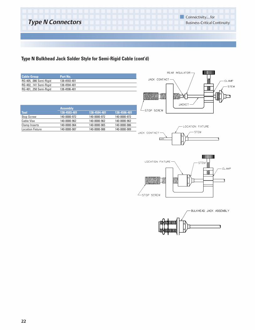
Type N Bulkhead Jack Solder Style for Semi-Rigid Cable
1. Identify connector parts (8 piece parts) and tools (4 piece parts).2. Strip cable jacket and dielectric to dimension shown. Do not nick
center conductor. Clean all debris from cable.3. Slide stem over cable jacket, keeping stem correctly oriented to end
of cable.4. Insert jack contact into rear insulator. Make sure insulator is
correctly oriented to contact. Place jack contact and rear insulatoronto center conductor, keeping insulator correctly oriented betweencable jacket and contact.
5. Slide stem away from jack contact. Insert contact into stop screwand clamp cable in vise. Tighten stop screw until light pressure isapplied between jack contact, rear insulator and cable jacket.
6. Solder jack contact to center conductor through solder hole using.020 (.051) diameter flux core solder wire. Use a minimum amount ofsolder for a good joint.
7. After solder joint has cooled, remove cable from vise and removeany excess solder from jack contact with a sharp blade and cleanall debris from contact and rear insulator.
8. Slide stem over rear insulator and tighten stem into location fixtureuntil stem bottoms out.
9. Insert cable into vise, but do not clamp. Insert jack contact into stopscrew and tighten location fixture until stop screw bottoms out.Clamp cable in vise.
10. Solder stem to cable jacket, using a minimum amount of solder for afull fillet joint. Allow assembly to cool before removing from vise.
11. After solder joint has cooled, un-clamp cable and remove locationfixture from stop screw and cable assembly. Insert front insulatorinto bulkhead jack body. Insert cable assembly into body and tightento 25-30 in-lbs.
12. Add gasket, lock washer and mounting nut when installingconnector to panel.
22
Connectivity....for
Business-Critical ContinuityType N Connectors
Type N Bulkhead Jack Solder Style for Semi-Rigid Cable (cont’d)
Cable Group Part No.RG-405, .086 Semi-Rigid 138-4593-401RG-402, .141 Semi-Rigid 138-4594-401RG-401, .250 Semi-Rigid 138-4596-401
AssemblyTool 138-4593-401 138-4594-401 138-4596-401Stop Screw 140-0000-972 140-0000-972 140-0000-972Cable Vise 140-0000-962 140-0000-962 140-0000-962Clamp Inserts 140-0000-964 140-0000-965 140-0000-986Location Fixture 140-0000-987 140-0000-988 140-0000-989
23
Connectivity....for
Business-Critical Continuity Type N Connectors
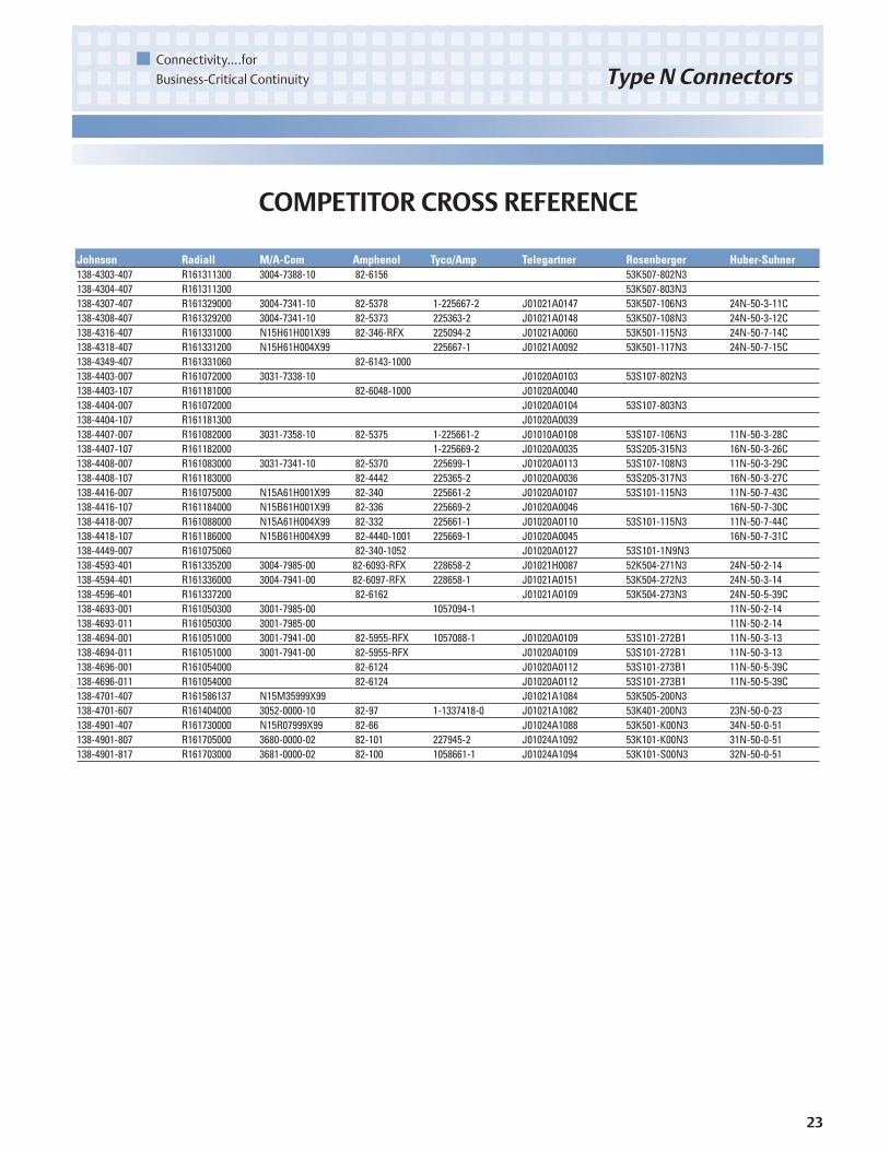
Johnson Radiall M/A-Com Amphenol Tyco/Amp Telegartner Rosenberger Huber-Suhner138-4303-407 R161311300 3004-7388-10 82-6156 53K507-802N3138-4304-407 R161311300 53K507-803N3138-4307-407 R161329000 3004-7341-10 82-5378 1-225667-2 J01021A0147 53K507-106N3 24N-50-3-11C138-4308-407 R161329200 3004-7341-10 82-5373 225363-2 J01021A0148 53K507-108N3 24N-50-3-12C138-4316-407 R161331000 N15H61H001X99 82-346-RFX 225094-2 J01021A0060 53K501-115N3 24N-50-7-14C138-4318-407 R161331200 N15H61H004X99 225667-1 J01021A0092 53K501-117N3 24N-50-7-15C138-4349-407 R161331060 82-6143-1000 138-4403-007 R161072000 3031-7338-10 J01020A0103 53S107-802N3138-4403-107 R161181000 82-6048-1000 J01020A0040138-4404-007 R161072000 J01020A0104 53S107-803N3138-4404-107 R161181300 J01020A0039138-4407-007 R161082000 3031-7358-10 82-5375 1-225661-2 J01010A0108 53S107-106N3 11N-50-3-28C138-4407-107 R161182000 1-225669-2 J01020A0035 53S205-315N3 16N-50-3-26C138-4408-007 R161083000 3031-7341-10 82-5370 225699-1 J01020A0113 53S107-108N3 11N-50-3-29C138-4408-107 R161183000 82-4442 225365-2 J01020A0036 53S205-317N3 16N-50-3-27C138-4416-007 R161075000 N15A61H001X99 82-340 225661-2 J01020A0107 53S101-115N3 11N-50-7-43C138-4416-107 R161184000 N15B61H001X99 82-336 225669-2 J01020A0046 16N-50-7-30C138-4418-007 R161088000 N15A61H004X99 82-332 225661-1 J01020A0110 53S101-115N3 11N-50-7-44C138-4418-107 R161186000 N15B61H004X99 82-4440-1001 225669-1 J01020A0045 16N-50-7-31C138-4449-007 R161075060 82-340-1052 J01020A0127 53S101-1N9N3138-4593-401 R161335200 3004-7985-00 82-6093-RFX 228658-2 J01021H0087 52K504-271N3 24N-50-2-14138-4594-401 R161336000 3004-7941-00 82-6097-RFX 228658-1 J01021A0151 53K504-272N3 24N-50-3-14138-4596-401 R161337200 82-6162 J01021A0109 53K504-273N3 24N-50-5-39C138-4693-001 R161050300 3001-7985-00 1057094-1 11N-50-2-14138-4693-011 R161050300 3001-7985-00 11N-50-2-14138-4694-001 R161051000 3001-7941-00 82-5955-RFX 1057088-1 J01020A0109 53S101-272B1 11N-50-3-13138-4694-011 R161051000 3001-7941-00 82-5955-RFX J01020A0109 53S101-272B1 11N-50-3-13138-4696-001 R161054000 82-6124 J01020A0112 53S101-273B1 11N-50-5-39C138-4696-011 R161054000 82-6124 J01020A0112 53S101-273B1 11N-50-5-39C138-4701-407 R161586137 N15M35999X99 J01021A1084 53K505-200N3138-4701-607 R161404000 3052-0000-10 82-97 1-1337418-0 J01021A1082 53K401-200N3 23N-50-0-23138-4901-407 R161730000 N15R07999X99 82-66 J01024A1088 53K501-K00N3 34N-50-0-51138-4901-807 R161705000 3680-0000-02 82-101 227945-2 J01024A1092 53K101-K00N3 31N-50-0-51138-4901-817 R161703000 3681-0000-02 82-100 1058661-1 J01024A1094 53K101-S00N3 32N-50-0-51
COMPETITOR CROSS REFERENCE

Emerson Network Power and the Emerson Network Power logo are trademarks and service marks of Emerson Electric Co. ©2006 Emerson Electric Co N06
Emerson Network Power.
The global leader in enabling business-critical continuity.
AC Power Systems
Connectivity
DC Power Systems
Embedded PowerInbound PowerIntegrated Cabinet Solutions
Outside PlantPrecision CoolingSite Monitoring and Services
Emerson Network Power Connectivity Solutions
Johnson
299 Johnson Avenue
Waseca, MN 56093
USA
Tel: 800.247.8256
Fax: 507.833.6287
www.EmersonNetworkPower.com/Connectivity
About Emerson Network Power
Connectivity Solutions
Emerson Network Power Connectivity Solutions,
an Emerson business, serves the needs of
wireless communications, telephony and data
networks, CATV, security systems, health care
and industrial facilities with a full spectrum of
broadband copper and fiber optic connectivity
products. For more information, visit
www.EmersonNetworkPower.com/Connectivity.
About Emerson
Emerson (NYSE: EMR), based in St. Louis, is a
global leader in bringing technology and
engineering together to provide innovative
solutions to customers through its network
power, process management, industrial
automation, climate technologies, and appliance
and tools businesses. Sales in fiscal 2005 were
$17.3 billion. For more information, visit
www.gotoemerson.com.
EmersonNetworkPower. com