type f6000 furnace - toolik field station::main...
TRANSCRIPT
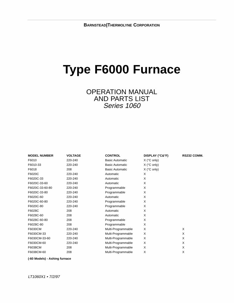
Type F6000 Furnace
OPERATION MANUALAND PARTS LIST
Series 1060
MODEL NUMBER VOLTAGE CONTROL DISPLAY (°C&°F) RS232 COMM.
F6010 220-240 Basic Automatic X (°C only)
F6010-33 220-240 Basic Automatic X (°C only)
F6018 208 Basic Automatic X (°C only)
F6020C 220-240 Automatic X
F6020C-33 220-240 Automatic X
F6020C-33-60 220-240 Automatic X
F6020C-33-60-80 220-240 Programmable X
F6020C-33-80 220-240 Programmable X
F6020C-60 220-240 Automatic X
F6020C-60-80 220-240 Programmable X
F6020C-80 220-240 Programmable X
F6028C 208 Automatic X
F6028C-60 208 Automatic X
F6028C-60-80 208 Programmable X
F6028C-80 208 Programmable X
F6030CM 220-240 Multi-Programmable X X
F6030CM-33 220-240 Multi-Programmable X X
F6030CM-33-60 220-240 Multi-Programmable X X
F6030CM-60 220-240 Multi-Programmable X X
F6038CM 208 Multi-Programmable X X
F6038CM-60 208 Multi-Programmable X X
(-60 Models) - Ashing furnace
1
BARNSTEAD|THERMOLYNE CORPORATION
LT1060X1 • 7/2/97
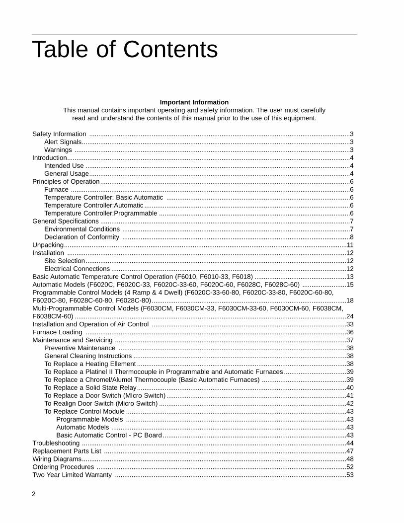
Important InformationThis manual contains important operating and safety information. The user must carefully
read and understand the contents of this manual prior to the use of this equipment.
Safety Information ..............................................................................................................................................3 Alert Signals..................................................................................................................................................3 Warnings ......................................................................................................................................................3
Introduction..........................................................................................................................................................4Intended Use ................................................................................................................................................4General Usage..............................................................................................................................................4
Principles of Operation........................................................................................................................................6Furnace ........................................................................................................................................................6Temperature Controller: Basic Automatic ....................................................................................................6Temperature Controller:Automatic ................................................................................................................6Temperature Controller:Programmable ........................................................................................................6
General Specifications ........................................................................................................................................7Environmental Conditions ............................................................................................................................7 Declaration of Conformity ............................................................................................................................8
Unpacking..........................................................................................................................................................11 Installation ........................................................................................................................................................12
Site Selection..............................................................................................................................................12Electrical Connections ................................................................................................................................12
Basic Automatic Temperature Control Operation (F6010, F6010-33, F6018) ..................................................13 Automatic Models (F6020C, F6020C-33, F6020C-33-60, F6020C-60, F6028C, F6028C-60) ........................15 Programmable Control Models (4 Ramp & 4 Dwell) (F6020C-33-60-80, F6020C-33-80, F6020C-60-80,F6020C-80, F6028C-60-80, F6028C-80)..........................................................................................................18 Multi-Programmable Control Models (F6030CM, F6030CM-33, F6030CM-33-60, F6030CM-60, F6038CM,F6038CM-60) ....................................................................................................................................................24 Installation and Operation of Air Control ..........................................................................................................33 Furnace Loading ..............................................................................................................................................36 Maintenance and Servicing ..............................................................................................................................37
Preventive Maintenance ............................................................................................................................38General Cleaning Instructions ....................................................................................................................38To Replace a Heating Ellement ..................................................................................................................38To Replace a Platinel II Thermocouple in Programmable and Automatic Furnaces ..................................39To Replace a Chromel/Alumel Thermocouple (Basic Automatic Furnaces) ..............................................39To Replace a Solid State Relay..................................................................................................................40To Replace a Door Switch (MIcro Switch) ..................................................................................................41To Realign Door Switch (Micro Switch) ......................................................................................................42To Replace Control Module ........................................................................................................................43
Programmable Models ........................................................................................................................43Automatic Models ................................................................................................................................43Basic Automatic Control - PC Board ....................................................................................................43
Troubleshooting ................................................................................................................................................44 Replacement Parts List ....................................................................................................................................47 Wiring Diagrams................................................................................................................................................48 Ordering Procedures ........................................................................................................................................52 Two Year Limited Warranty ..............................................................................................................................53
2
Table of Contents
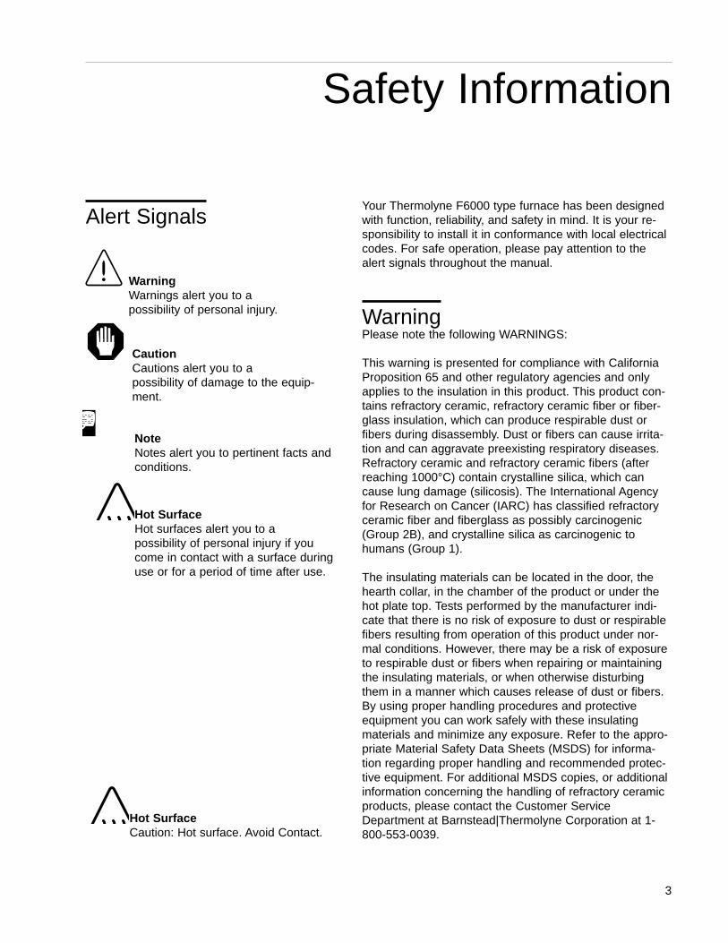
Your Thermolyne F6000 type furnace has been designedwith function, reliability, and safety in mind. It is your re-sponsibility to install it in conformance with local electricalcodes. For safe operation, please pay attention to thealert signals throughout the manual.
WarningPlease note the following WARNINGS:
This warning is presented for compliance with CaliforniaProposition 65 and other regulatory agencies and onlyapplies to the insulation in this product. This product con-tains refractory ceramic, refractory ceramic fiber or fiber-glass insulation, which can produce respirable dust orfibers during disassembly. Dust or fibers can cause irrita-tion and can aggravate preexisting respiratory diseases.Refractory ceramic and refractory ceramic fibers (afterreaching 1000°C) contain crystalline silica, which cancause lung damage (silicosis). The International Agencyfor Research on Cancer (IARC) has classified refractoryceramic fiber and fiberglass as possibly carcinogenic(Group 2B), and crystalline silica as carcinogenic tohumans (Group 1).
The insulating materials can be located in the door, thehearth collar, in the chamber of the product or under thehot plate top. Tests performed by the manufacturer indi-cate that there is no risk of exposure to dust or respirablefibers resulting from operation of this product under nor-mal conditions. However, there may be a risk of exposureto respirable dust or fibers when repairing or maintainingthe insulating materials, or when otherwise disturbingthem in a manner which causes release of dust or fibers.By using proper handling procedures and protectiveequipment you can work safely with these insulatingmaterials and minimize any exposure. Refer to the appro-priate Material Safety Data Sheets (MSDS) for informa-tion regarding proper handling and recommended protec-tive equipment. For additional MSDS copies, or additionalinformation concerning the handling of refractory ceramicproducts, please contact the Customer ServiceDepartment at Barnstead|Thermolyne Corporation at 1-800-553-0039.
3
Safety Information
WarningWarnings alert you to a possibility of personal injury.
CautionCautions alert you to a possibility of damage to the equip-ment.
NoteNotes alert you to pertinent facts andconditions.
Hot SurfaceHot surfaces alert you to a possibility of personal injury if youcome in contact with a surface duringuse or for a period of time after use.
Alert Signals
Hot SurfaceCaution: Hot surface. Avoid Contact.
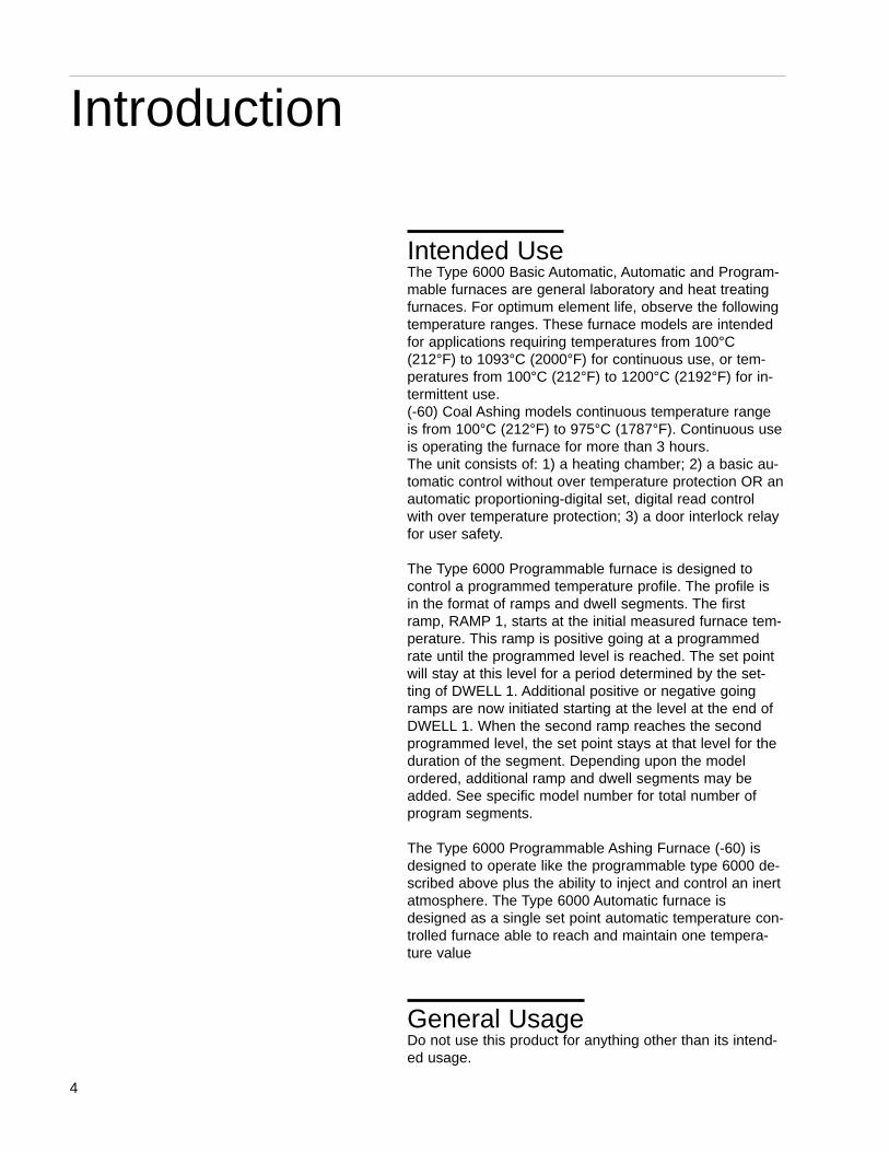
Intended UseThe Type 6000 Basic Automatic, Automatic and Program-mable furnaces are general laboratory and heat treatingfurnaces. For optimum element life, observe the followingtemperature ranges. These furnace models are intendedfor applications requiring temperatures from 100°C(212°F) to 1093°C (2000°F) for continuous use, or tem-peratures from 100°C (212°F) to 1200°C (2192°F) for in-termittent use. (-60) Coal Ashing models continuous temperature rangeis from 100°C (212°F) to 975°C (1787°F). Continuous useis operating the furnace for more than 3 hours.The unit consists of: 1) a heating chamber; 2) a basic au-tomatic control without over temperature protection OR anautomatic proportioning-digital set, digital read controlwith over temperature protection; 3) a door interlock relayfor user safety.
The Type 6000 Programmable furnace is designed tocontrol a programmed temperature profile. The profile isin the format of ramps and dwell segments. The firstramp, RAMP 1, starts at the initial measured furnace tem-perature. This ramp is positive going at a programmedrate until the programmed level is reached. The set pointwill stay at this level for a period determined by the set-ting of DWELL 1. Additional positive or negative goingramps are now initiated starting at the level at the end ofDWELL 1. When the second ramp reaches the secondprogrammed level, the set point stays at that level for theduration of the segment. Depending upon the modelordered, additional ramp and dwell segments may beadded. See specific model number for total number ofprogram segments.
The Type 6000 Programmable Ashing Furnace (-60) isdesigned to operate like the programmable type 6000 de-scribed above plus the ability to inject and control an inertatmosphere. The Type 6000 Automatic furnace isdesigned as a single set point automatic temperature con-trolled furnace able to reach and maintain one tempera-ture value
General UsageDo not use this product for anything other than its intend-ed usage.
4
Introduction
5
INTRODUCTION
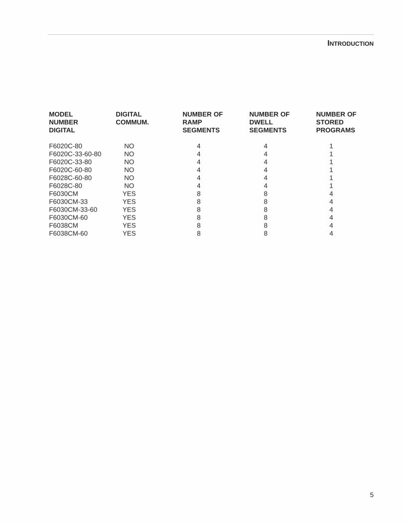
MODEL DIGITAL NUMBER OF NUMBER OF NUMBER OFNUMBER COMMUM. RAMP DWELL STOREDDIGITAL SEGMENTS SEGMENTS PROGRAMS
F6020C-80 NO 4 4 1F6020C-33-60-80 NO 4 4 1F6020C-33-80 NO 4 4 1F6020C-60-80 NO 4 4 1F6028C-60-80 NO 4 4 1F6028C-80 NO 4 4 1F6030CM YES 8 8 4F6030CM-33 YES 8 8 4F6030CM-33-60 YES 8 8 4F6030CM-60 YES 8 8 4F6038CM YES 8 8 4F6038CM-60 YES 8 8 4
Furnace The furnace chamber is heated by four electric resistanceheaters which are embedded in a refractory material. Thechamber is insulated with a ceramic fiber insulation. Thecontrol is located under the furnace chamber and is wellinsulated from the heat generated in the furnace chamber.A door safety switch removes power to the heating ele-ments whenever the furnace door is opened. The choicesof temperature controllers are as follows:
Temperature Controller: “BasicAutomatic” The basic automatic control provides simple automaticcontrol to one set point temperature. A single digital dis-play will indicate either furnace chamber temperature orset point temperature. This controller does not provideover temperature protection.
Temperature Controller:“Automatic” This furnace controller consists of a microprocessorbased three mode temperature controller having adjust-able over temperature protection and appropriate outputswitching devices to control the furnace.
Temperature Controller:“Programmable” This furnace controller consists of a microprocessorbased three mode temperature controller/programmerwith adjustable over temperature protection and appropri-ate output switching devices to control the furnace.
6
Principles of Operation
NoteWhen in the program RUN mode, theprogrammer/controller serves to pro-vide a programmed temperature pro-file as described earlier. When in theAUTOMATIC mode, the unit servesas a single set point automatic tem-perature controller.
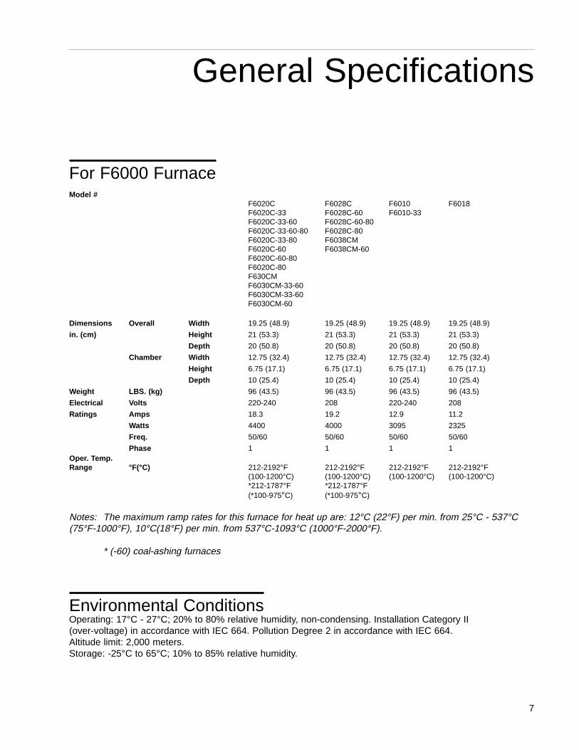
For F6000 FurnaceModel #
F6020C F6028C F6010 F6018F6020C-33 F6028C-60 F6010-33F6020C-33-60 F6028C-60-80F6020C-33-60-80 F6028C-80F6020C-33-80 F6038CMF6020C-60 F6038CM-60F6020C-60-80F6020C-80F630CMF6030CM-33-60F6030CM-33-60F6030CM-60
Dimensions Overall Width 19.25 (48.9) 19.25 (48.9) 19.25 (48.9) 19.25 (48.9)
in. (cm) Height 21 (53.3) 21 (53.3) 21 (53.3) 21 (53.3)
Depth 20 (50.8) 20 (50.8) 20 (50.8) 20 (50.8)
Chamber Width 12.75 (32.4) 12.75 (32.4) 12.75 (32.4) 12.75 (32.4)
Height 6.75 (17.1) 6.75 (17.1) 6.75 (17.1) 6.75 (17.1)
Depth 10 (25.4) 10 (25.4) 10 (25.4) 10 (25.4)
Weight LBS. (kg) 96 (43.5) 96 (43.5) 96 (43.5) 96 (43.5)
Electrical Volts 220-240 208 220-240 208
Ratings Amps 18.3 19.2 12.9 11.2
Watts 4400 4000 3095 2325
Freq. 50/60 50/60 50/60 50/60
Phase 1 1 1 1Oper. Temp.Range °F(°C) 212-2192°F 212-2192°F 212-2192°F 212-2192°F
(100-1200°C) (100-1200°C) (100-1200°C) (100-1200°C)*212-1787°F *212-1787°F(*100-975°C) (*100-975°C)
Notes: The maximum ramp rates for this furnace for heat up are: 12°C (22°F) per min. from 25°C - 537°C(75°F-1000°F), 10°C(18°F) per min. from 537°C-1093°C (1000°F-2000°F).
* (-60) coal-ashing furnaces
Environmental Conditions Operating: 17°C - 27°C; 20% to 80% relative humidity, non-condensing. Installation Category II (over-voltage) in accordance with IEC 664. Pollution Degree 2 in accordance with IEC 664. Altitude limit: 2,000 meters.Storage: -25°C to 65°C; 10% to 85% relative humidity.
7
General Specifications
Declaration of Conformity (-33 Models only)Barnstead|Thermolyne hereby declares under its sole re-sponsibility that this product conforms with the technicalrequirements of the following standards:EMC: EN 50081-1 Generic Emission Standard; EN
50082-1 Generic Immunity Standard;Safety: IEC 1010-1-92 Safety requirements for electrical
equipment for measurement, control, and laboratory use; Part I: General Requirements
IEC 1010-2-010 Part II: Particular requirements for laboratory equipment for the heating of materials
per the provisions of the Electromagnetic CompatibilityDirective 89/336/EEC, as amended by 92/31/EEC and93/68/EEC, and per the provisions of the Low Voltage Directive 73/23/EEC, as amended by 93/68/EEC.
The authorized representative located within the Europe-an Community is:
Electrothermal Engineering Ltd.419 Sutton RoadSouthend On SeaEssex SS2 5PHUnited Kingdom
Copies of the Declaration of Conformity are availableupon request.
8
GENERAL SPECIFICATIONS
9
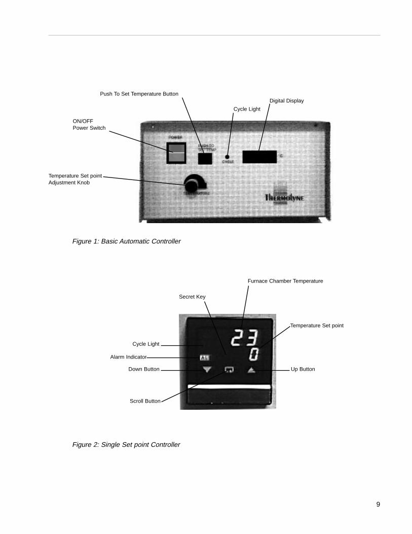
ON/OFFPower Switch
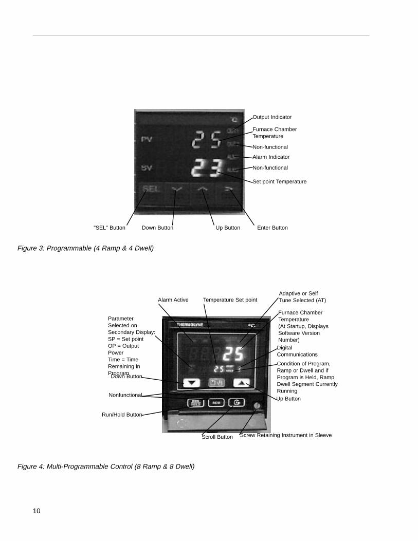
Cycle Light
Push To Set Temperature Button
Temperature Set pointAdjustment Knob
Furnace Chamber Temperature
Temperature Set point
Alarm Indicator
Cycle Light
Secret Key
Down Button Up Button
Scroll Button
Digital Display
Figure 1: Basic Automatic Controller
Figure 2: Single Set point Controller
10
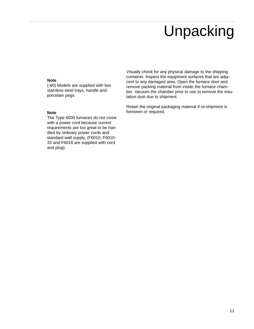
Output Indicator
Enter ButtonUp Button
Furnace ChamberTemperature
Non-functional
Alarm Indicator
Non-functional
Set point Temperature
Down Button"SEL" Button
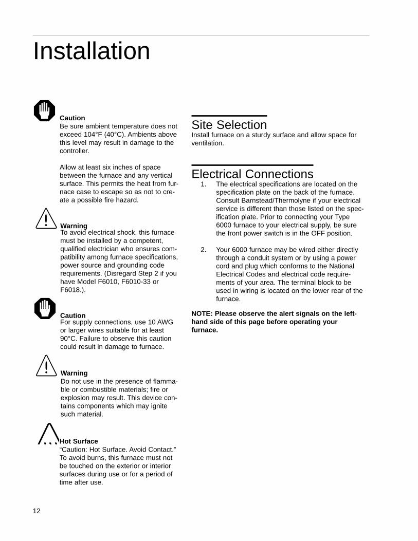
Alarm Active Temperature Set point
Screw Retaining Instrument in Sleeve
Furnace ChamberTemperature(At Startup, DisplaysSoftware VersionNumber)DigitalCommunications
Condition of Program,Ramp or Dwell and ifProgram is Held, RampDwell Segment CurrentlyRunningUp Button
Run/Hold Button
Down Button
ParameterSelected onSecondary Display:SP = Set pointOP = OutputPowerTime = TimeRemaining inProgram
Adaptive or SelfTune Selected (AT)
Scroll Button
Nonfunctional
Figure 3: Programmable (4 Ramp & 4 Dwell)
Figure 4: Multi-Programmable Control (8 Ramp & 8 Dwell)
Visually check for any physical damage to the shippingcontainer. Inspect the equipment surfaces that are adja-cent to any damaged area. Open the furnace door andremove packing material from inside the furnace cham-ber. Vacuum the chamber prior to use to remove the insu-lation dust due to shipment.
Retain the original packaging material if re-shipment isforeseen or required.
11
Unpacking
Note(-60) Models are supplied with twostainless steel trays, handle andporcelain pegs.
NoteThe Type 6000 furnaces do not comewith a power cord because currentrequirements are too great to be han-dled by ordinary power cords andstandard wall supply. (F6010, F6010-33 and F6018 are supplied with cordand plug).
Site SelectionInstall furnace on a sturdy surface and allow space forventilation.
Electrical Connections1. The electrical specifications are located on the
specification plate on the back of the furnace.Consult Barnstead/Thermolyne if your electricalservice is different than those listed on the spec-ification plate. Prior to connecting your Type6000 furnace to your electrical supply, be surethe front power switch is in the OFF position.
2. Your 6000 furnace may be wired either directlythrough a conduit system or by using a powercord and plug which conforms to the NationalElectrical Codes and electrical code require-ments of your area. The terminal block to beused in wiring is located on the lower rear of thefurnace.
NOTE: Please observe the alert signals on the left -hand side of this page before operating your furnace.
12
Installation
CautionBe sure ambient temperature does notexceed 104°F (40°C). Ambients abovethis level may result in damage to thecontroller.
Allow at least six inches of spacebetween the furnace and any verticalsurface. This permits the heat from fur-nace case to escape so as not to cre-ate a possible fire hazard.
WarningTo avoid electrical shock, this furnacemust be installed by a competent,qualified electrician who ensures com-patibility among furnace specifications,power source and grounding coderequirements. (Disregard Step 2 if youhave Model F6010, F6010-33 orF6018.).
CautionFor supply connections, use 10 AWGor larger wires suitable for at least90°C. Failure to observe this cautioncould result in damage to furnace.
Hot Surface“Caution: Hot Surface. Avoid Contact.”To avoid burns, this furnace must notbe touched on the exterior or interiorsurfaces during use or for a period oftime after use.
WarningDo not use in the presence of flamma-ble or combustible materials; fire orexplosion may result. This device con-tains components which may ignitesuch material.
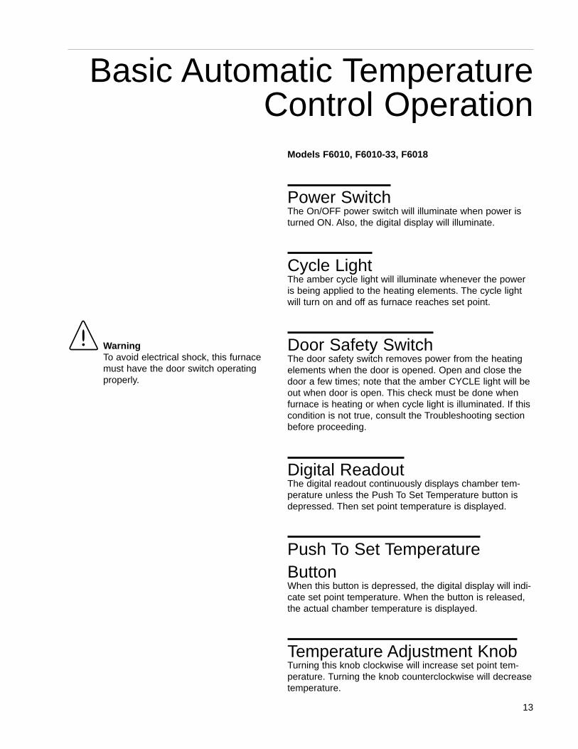
Models F6010, F6010-33, F6018
Power SwitchThe On/OFF power switch will illuminate when power isturned ON. Also, the digital display will illuminate.
Cycle LightThe amber cycle light will illuminate whenever the poweris being applied to the heating elements. The cycle lightwill turn on and off as furnace reaches set point.
Door Safety SwitchThe door safety switch removes power from the heatingelements when the door is opened. Open and close thedoor a few times; note that the amber CYCLE light will beout when door is open. This check must be done whenfurnace is heating or when cycle light is illuminated. If thiscondition is not true, consult the Troubleshooting sectionbefore proceeding.
Digital ReadoutThe digital readout continuously displays chamber tem-perature unless the Push To Set Temperature button isdepressed. Then set point temperature is displayed.
Push To Set TemperatureButtonWhen this button is depressed, the digital display will indi-cate set point temperature. When the button is released,the actual chamber temperature is displayed.
Temperature Adjustment KnobTurning this knob clockwise will increase set point tem-perature. Turning the knob counterclockwise will decreasetemperature.
13
Basic Automatic TemperatureControl Operation
WarningTo avoid electrical shock, this furnacemust have the door switch operatingproperly.
Temperature ControllerThis controller provides accurate control at one singletemperature setting. To set temperature, simply:
1. Turn Power switch ON.
2. While depressing the Push To Set Temperaturebutton, turn the temperature knob until youreach the desired set point temperature as indi-cated on digital display.
3. Release the Push To Set Temperature button.
The digital display will now indicate the actual chambertemperature. The furnace will heat to the new set pointtemperature. The CYCLE light will remain on until the fur-nace temperature is within 1°C of the set point tempera-ture; then the CYCLE light will turn on and off as the con-troller maintains the set point temperature.
Sensor Break ProtectionThis controller provides sensor break protection in theevent the thermocouple opens. If an open thermocouplecondition occurs, the digital display will indicate 5 degreesor less and the power to the heating element will be shutoff (CYCLE light will extinguish).
14
BASIC AUTOMATIC TEMPERATURE CONTROL OPERATION
NoteIf at any time the TemperatureAdjustment knob is turned in eitherdirection, the set point will change,even if the Push To Set Temperaturebutton is not depressed. To view thecurrent set point temperature, depressthe Push To Set Temperature button.
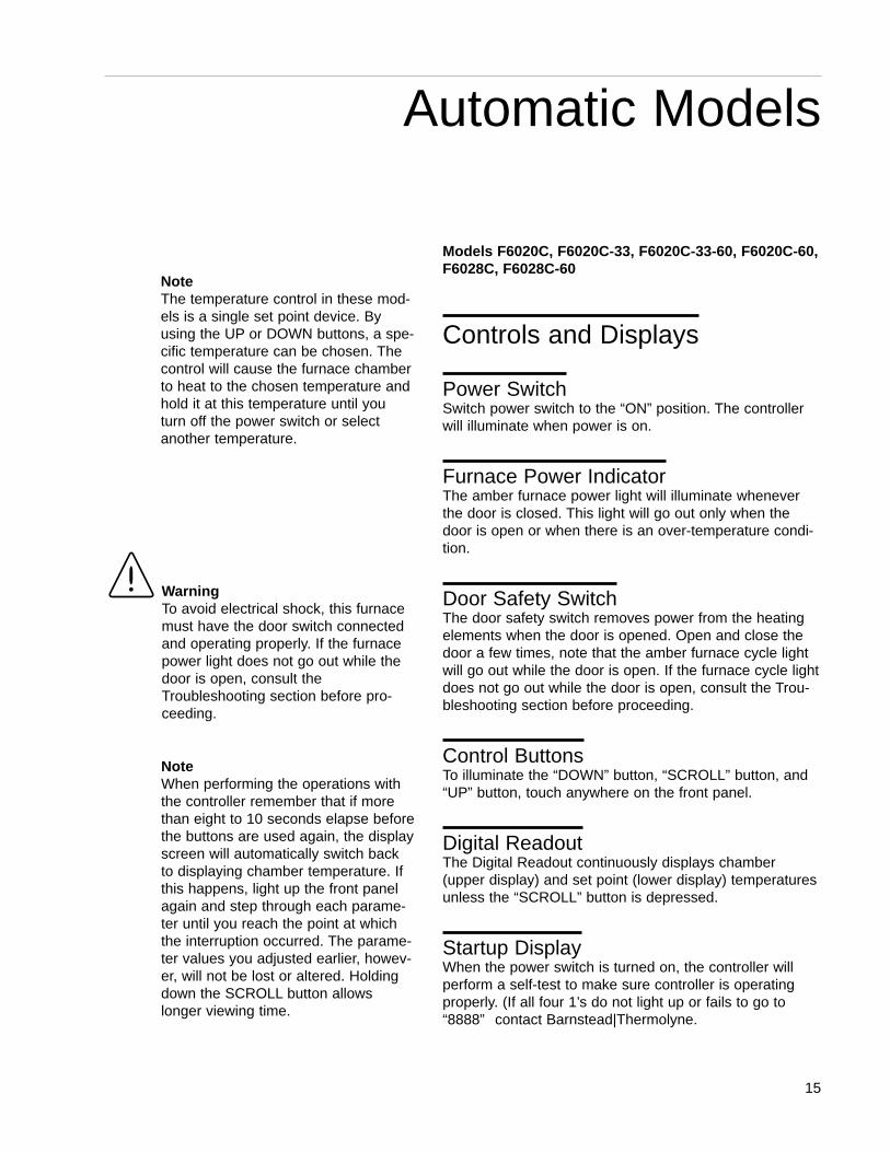
Models F6020C, F6020C-33, F6020C-33-60, F6020C-60,F6028C, F6028C-60
Controls and Displays
Power Switch Switch power switch to the “ON” position. The controllerwill illuminate when power is on.
Furnace Power Indicator The amber furnace power light will illuminate wheneverthe door is closed. This light will go out only when thedoor is open or when there is an over-temperature condi-tion.
Door Safety Switch The door safety switch removes power from the heatingelements when the door is opened. Open and close thedoor a few times, note that the amber furnace cycle lightwill go out while the door is open. If the furnace cycle lightdoes not go out while the door is open, consult the Trou-bleshooting section before proceeding.
Control ButtonsTo illuminate the “DOWN” button, “SCROLL” button, and“UP” button, touch anywhere on the front panel.
Digital ReadoutThe Digital Readout continuously displays chamber(upper display) and set point (lower display) temperaturesunless the “SCROLL” button is depressed.
Startup Display When the power switch is turned on, the controller willperform a self-test to make sure controller is operatingproperly. (If all four 1’s do not light up or fails to go to“8888” contact Barnstead|Thermolyne.
15
Automatic Models
NoteThe temperature control in these mod-els is a single set point device. Byusing the UP or DOWN buttons, a spe-cific temperature can be chosen. Thecontrol will cause the furnace chamberto heat to the chosen temperature andhold it at this temperature until youturn off the power switch or selectanother temperature.
WarningTo avoid electrical shock, this furnacemust have the door switch connectedand operating properly. If the furnacepower light does not go out while thedoor is open, consult theTroubleshooting section before pro-ceeding.
NoteWhen performing the operations withthe controller remember that if morethan eight to 10 seconds elapse beforethe buttons are used again, the displayscreen will automatically switch backto displaying chamber temperature. Ifthis happens, light up the front panelagain and step through each parame-ter until you reach the point at whichthe interruption occurred. The parame-ter values you adjusted earlier, howev-er, will not be lost or altered. Holdingdown the SCROLL button allowslonger viewing time.
Adjusting Furnace Set pointTemperature
• To illuminate the “DOWN” button, “SCROLL”button, and “UP” button, touch anywhere on thefront panel.
• Push the “UP” button or the “DOWN” button tomodify the temperature set point (lower digitaldisplay).
Tuning This control incorporates a self tuning feature which de-termines the optimum control parameters for the besttemperature accuracy. We recommend that you tune thefurnace to your specific application to obtain the best re-sults. Perform the following procedures when you first setup your furnace and each time you change your load typeor operating temperature.
To tune your furnace:
1. Load your furnace with a load characteristic ofthose you intend to heat in it.
2. Set the furnace’s set point to the temperatureyou intend to use for your application.
3. Push the “SCROLL” button until ‘tunE” appears.To start the tuning function, push the “UP” but-ton.
When the tuning process is started, the lower display willflash ‘tunE” along with the furnace temperature set point.During tuning, the temperature set point cannot bechanged. To change temperature set point ‘tunE” must beturned “OFF.” (To stop the tuning function, push the“DOWN” button.)
16
AUTOMATIC MODELS
CautionDo not exceed limitations for continu-ous or intermittent operating tempera-ture shown in the GeneralSpecifications section. Exceedingthese limits will result in severelyreduced heating element life.
NoteIf the power to the furnace is turned offor interrupted while in tuning, uponreturning power to the furnace, thecontroller display will indicate, “LinEFAIL” because sampled data could bequestionnable.
If the controller cannot maintain tem-perature set point, “tunE FAIL” willappear on display.First, correct theproblem responsible for not maintain-inig the temperature set point, thenrestart the tuning procedure.
Changing TemperatureIndication Push “SCROLL” button once, “°C” will appear. This indi-cates temperature measurement. (Contact Thermolyne ifcontrol needs to be changed to °F.)
Setting the High AlarmTemperature Over TemperatureProtection (OTP) Push “SCROLL” button until “AL.SP” (Alarm Set point) ap-pears. The lower display should indicate 1100°C.Depress either the “UP” or “DOWN” button to select theOTP value you desire. Thermolyne recommends that youset the value either at the maximum operating tempera-ture of the furnace or a value of 20 degrees above yourworking temperature if you desire to provide protection foryour workload.
17
AUTOMATIC MODELS
NoteHIAL-HIGH ALARM (over temperatureprotection - OTP). The controller is fit-ted with a mechanical relay which isde-energized in the alarm mode. Thisrelay, when de-energized, removespower from the heating elements. Ifthe primary control circuit fails, theOTP will control the furnace tempera-ture at the preset value you haveentered. It does not shut off the fur-nace but will maintain the chambertemperature at that value.
(4 Ramp & 4 Dwell)F6020C-33-60-80, F6020C-33-80, F6020C-60-80,F6020C-80, F6028C-60-80, F6028C-80
This controller consists of a microprocessor based three-mode (Proportional, Integral, Derivative), programmabletemperature controller with “Fuzzy” logic capability, pro-grammable over-temperature protection and appropriateoutput switching devices to control the furnace. The digitalreadout continuously displays chamber (upper display)and set point (lower display) temperatures unless the“SEL” button is depressed.
The programmable control can be used as a single setpoint control or as a programmable control.
Single Set Point OperationTo use as a single set point control simply push “UP” or“DOWN” button to choose a specific temperature.
1. The set point temperature presently set in thecontrol will be read out on the lower display
2. To change this set point, depress the “UP” or“DOWN” button until the desired set point value is displayed, then release the button.
3. At this point, the furnace will begin to heat if thenew set point temperature you have chosen ishigher than the present chamber temperature.
Programmed Operation
Control ParametersYou can gain access to the control parameters by holdingthe “SEL” button depressed for about 3 seconds. “LoCt”will be displayed in the upper display.
Depressing “SEL” once again shows the next parameterand its current value on the display. The parameter valuecan either be modified with the buttons or left unmodified.Pressing the enter button (>) will allow you to modify thecurrent value using the “Up” and “Down” buttons. Press
18
Programmable Control Models
WarningTo avoid electrical shock, this furnacemust have the door switch operatingproperly.
NoteFor optimum control of a single setpoint operation, set the “CTrL” parame-ters to “FUZY” to take advantage ofthe controller’s fuzzy logic capabilities.
NoteThe furnace will begin to heat to thecurrent set point temperature when youturn the power switch ON.To examinethe control parameters without heatingthe furnace, depress and hold theDOWN button until the set point (lower)display reads “20.”
NoteWhen examining the parameters, if youdepress and release either the “SEL,”“UP” or “DOWN” buttonbottom andmore than 1 minute elapses before thebuttons are used again, the displayscreen will automatically switch to dis-playing chamber temperature. If thishappens, you will have to step througheach parameter until you reach thepoint at which the interruptionoccurred. The parameter values youchecked earlier, however, will not belost or altered.
the enter button again to set the new value as the currentvalue. (See “Programming Controller” for information onprogramming.)
The control parameters in order are:
LoCt - Parameter lock level. Determines the number ofparameters displayed when you press “SEL”. It should beset to “0002.” If it does not, set to “0002.”
Nod - Mode. By pushing “UP” or “DOWN” buttons, thiscan be set to “Auto” or “NAn” (Manual). Set to “Auto”. InManual mode, you must enter values to control the fur-nace chamber temperature.
At - Autotuning feature. Will automatically set optimumP.I.D. values for your process. For Tuning, set to “on.” Fornormal operation, set to “oFF.”
StAt - Status. Displays current status of program andcannot be changed.
Tine - Time. Displays the time remaining in the currentprogram.
ProG - Program options. Can be set to one of three op-tions: “oFF”, “rUn” or “hold”. “oFF” will stop any runningprogram and reset the program to the beginning. “rUn”will start a program from the beginning or resume a pro-gram from “hold” from the point it was held. “hold” willinterrupt a running program without resetting the programto the beginning.
Sü-1 - Set point 1. The temperature at which the firstramp is aiming and at which the first dwell will be held.
tN1r - Ramp time 1. The time the controller will take tocharge the chamber temperature from its present temper-ature to the value of Set point 1. This time may be limitedby the physical capabilities of the furnace.
tN1S - Dwell time 1. The length of time the controller willhold the furnace at the Set point 1 temperature.
Sü-2 - Set point 2.
tN2r - Ramp time 2.
19
PROGRAMMABLE CONTROL MODELS
tN2S - Dwell time 2.
Sü-3 - Set point 3.
tN3R - Ramp time 3.
tN3S - Dwell time 3.
Sü-4 - Set point 4.
tN4r - Ramp time 4.
tN4S - Dwell time 4.
P-on - Power-on start. Push the “Up” or “Down” Buttonsto set to “Yes” or “No.” When set to “Yes,” your furnacewill immediately begin running the set program when youpower on your furnace. For most applications, set to“No.”
The next three parameters - Proportional band, Integraland Derivative - are the three control parameters of aP.I.D. control system. The values for these parametersare set during the tuning process. You should not changethem; doing so may cause your controller to operateincorrectly.
P - Proportional band
i - Integral
d - Derivative
AL1T - Alarm type. This parameter determines how thecontroller responds to any alarm input. It should display“0031.” If it does not, set it to “0031.”
AL11 - Furnace over temperature alarm. This parame-ter determines the absolute upper limit on the furnacechamber temperature. We recommend a setting of“1200°C” since 1200°C is the maximum temperature yourfurnace can obtain without damage to furnace compo-nents. You may wish to set the parameter lower if youneed to ensure a crucial process is protected from high temperature.
AL12 - High deviation alarm. This parameter determines
20
PROGRAMMABLE CONTROL MODELS
NoteOver Temperature Protection (OTP):The controller is fitted with a mechani-cal relay which is de-energized in thealarm mode. This relay, when de-ener-gized, removes power from the heatingelements. If the primary control circuitfails, the OTP will control the furnacetemperature at the value you haveentered for AL11. It does not shut offthe furnace, but will maintain thechamber temperature at that value.
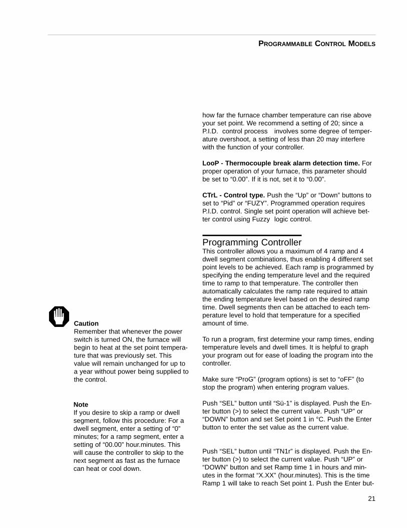
how far the furnace chamber temperature can rise aboveyour set point. We recommend a setting of 20; since aP.I.D. control process involves some degree of temper-ature overshoot, a setting of less than 20 may interferewith the function of your controller.
LooP - Thermocouple break alarm detection time. Forproper operation of your furnace, this parameter shouldbe set to “0.00”. If it is not, set it to “0.00”.
CTrL - Control type. Push the “Up” or “Down” buttons toset to “Pid” or “FUZY”. Programmed operation requiresP.I.D. control. Single set point operation will achieve bet-ter control using Fuzzy logic control.
Programming ControllerThis controller allows you a maximum of 4 ramp and 4dwell segment combinations, thus enabling 4 different setpoint levels to be achieved. Each ramp is programmed byspecifying the ending temperature level and the requiredtime to ramp to that temperature. The controller thenautomatically calculates the ramp rate required to attainthe ending temperature level based on the desired ramptime. Dwell segments then can be attached to each tem-perature level to hold that temperature for a specifiedamount of time.
To run a program, first determine your ramp times, endingtemperature levels and dwell times. It is helpful to graphyour program out for ease of loading the program into thecontroller.
Make sure “ProG” (program options) is set to “oFF” (tostop the program) when entering program values.
Push “SEL” button until “Sü-1” is displayed. Push the En-ter button (>) to select the current value. Push “UP” or“DOWN” button and set Set point 1 in °C. Push the Enterbutton to enter the set value as the current value.
Push “SEL” button until “TN1r” is displayed. Push the En-ter button (>) to select the current value. Push “UP” or“DOWN” button and set Ramp time 1 in hours and min-utes in the format “X.XX” (hour.minutes). This is the timeRamp 1 will take to reach Set point 1. Push the Enter but-
21
PROGRAMMABLE CONTROL MODELS
CautionRemember that whenever the powerswitch is turned ON, the furnace willbegin to heat at the set point tempera-ture that was previously set. Thisvalue will remain unchanged for up toa year without power being supplied tothe control.
NoteIf you desire to skip a ramp or dwellsegment, follow this procedure: For adwell segment, enter a setting of “0”minutes; for a ramp segment, enter asetting of “00.00” hour.minutes. Thiswill cause the controller to skip to thenext segment as fast as the furnacecan heat or cool down.
ton to enter the set value as the current value.
Push “SEL” button until “TH1S” is displayed. Push the En-ter button (>) to select the current value. Push“UP” or “DOWN” button and set Dwell time 1 in hours andminutes in the format “X.XX” (hour.minutes). Push theEnter button to enter the set value as the current value.
Set “Sü-2” “TN2r” “TN2S” “Sü-3” “TN3r” “TN3S” “Sü-4”“TN4r” and “TN4S” in the same manner as “Sü-1” “TN1r”“TN1S”.
Program ExecutionPush “SEL” button until “ProG” is displayed. Pushing “UP”or “DOWN” button, select “run.” When “run” is selected,the program will start from the actual furnace temperatureat that point in time.
Set pointWhile the program is in “run” or “Hold,” the set pointshown on the bottom display is the current working setpoint.
Program EndWhen the program ends, the controller will hold the fur-nace at the value of Set point 4 until you stop the pro-gram
Program StopTo stop program, push “SEL” button until “ProG” is dis-played. Push “UP” or “DOWN” button until “oFF” is dis-played. This will terminate program.
Self Tuning FeatureThis programmable control has an automatic tuning fea-ture which installs optimum tuning parameters to give thebest temperature accuracy with your load and set point orprogram. No manual loading of tuning parameters isneeded. Barnstead|Thermolyne highly recommendsusing this feature to provide the best temperatureaccuracy the controller can attain . Use this feature the
22
PROGRAMMABLE CONTROL MODELS
NoteThe temperature control in these mod-els is a programmable and automaticsingle set point device. When the pro-gram has ended, the controller willmaintain the chamber temperature at avalue equal to the last programmedlevel (Set point 4) until the program iscanceled. It will not automatically coolto ambient unless Set point 4 is set atambient. When a program is canceled,the controller will maintain the cham-ber temperature at a value equal to thesingle set point mode set point.
first time you use your furnace and each time you changeyour set point or program or the type of load you areheating. To use the Tuning feature:
1. Select the temperature at which you intend tooperate. If you will be running a program, enterthe value of Set point 1 as a single set point.
2. Load your furnace with a characteristic sampleof the load you will be heating.
3. Push “SEL” button until “AT” is displayed, thenpush “UP” or “DOWN” button to turn “AT” “on.”
During the operation, “TunE” flashes in the lower display.Do not make any adjustments to the controller parame-ters during this period. The self tuning is finished when“TunE” no longer flashes in the lower display.Self tuning will calculate values for:
Proportional band - PIntegral - IDerivative - d
• Self tuning cannot be initiated while running aprogram.
• A power failure will cause the AT parameter torevert back to “OFF”. (Reset tune parameter to “ON” using the “UP” button).
• In the case of alarm conditions during tuning,those conditions will flash alternately with “TunE.”
The next time you use your furnace, push “SEL” buttonuntil “AT” is displayed, then push “UP” or “DOWN” buttonto turn tune “oFF.”
23
PROGRAMMABLE CONTROL MODELS
NoteFor processes which cannot toleratethe overshoot naturally generated dur-ing the tuning process, select “Lo”rather than on for the “AT” setting. The“Lo” setting will tune your furnace at atemperature below your set point, thenapply the result to your set point. Thisapproach prevents the necessary tun-ing overshoot from exceeding youractual set point.
(8 ramp & 8 dwell) F6030CM, F6030CM-33, F6030CM-33-60, F6030CM-60,F6038CM, F6038CM-60
Controls and Displays
Digital Readout:The digital readout continuously displays chamber (upperdisplay) and set point (lower display) temperatures unlessthe scroll button is depressed.
If the scroll button is depressed and released, the lowerdisplay will indicate output power (OP) or set point (SP).This is referred to as the “short scroll.” Continued singlestep action of scroll button will cause lower display to al-ternate between set point (SP) and output power (OP).
To enter the main scroll list (list of all controller parame-ters that are accessed through front keyboard), the scrollbutton should be held depressed. PR1 (program ramprate 1) will appear. To progress through the parameter list,the scroll button must first be released; subsequent singlestep depression will advance you through the list. Rapidprogression through the parameter list is achieved byholding the scroll button depressed.
See Parameters for a list of the controller parameters inorder.
Power Switch Turn power switch to the “ON” position.
Furnace Power IndicatorThe amber furnace power light will illuminate wheneverthe door is closed. This light will go out only when thedoor is open or when there is an over-temperature condi-tion.
Door Safety Switch The door safety switch removes power from the heatingelements when the door is opened. Open and close door
24
Multi-Programmable Models
NoteWhen performing operations with thecontroller, if you depress and releaseeither the SCROLL, Up or DOWNpush button and more than eight sec-onds elapse before the buttons areused again, the display screen willautomatically switch back to displayingset point temperature. If this happens,you will have to step through eachparameter until you reach the point atwhich the interruption occurred, Theparameter values you adjusted earlier,however, will not be lost or altered.
NoteTo change from °C indication to °Findication, contactBarnstead|Thermolyne.
CautionRemember that whenever the powerswitch is turned ON, the furnace willbegin to heat at the set point tempera-ture that was previously set in. Thisvalue will remain unchanged for up toa year without power being applied tothe control.
WarningTo avoid electrical shock, this furnacemust have the door switch connectedand operating properly. If the furnacecycle light does not go out while thedoor is open, consult theTroubleshooting section before pro-ceeding.
a few times, note that the amber furnace cycle light willgo out while the door is open. If the furnace cycle lightdoes not go out while the door is open, consult theTroubleshooting section before proceeding.
ParametersPnr - Program Number . The program number of the pro-gram you are going to work with. By pushing the up ordown button you can select a program numbered from 1to 4.
PR1 - Program Ramp Rate . The rate of heat increase ordecrease in °C/minutes. Pushing the up or down buttonwill give current setting of this ramp.
PL1 - Program Level. The temperature to which the fur-nace needs to attain. Push up or down button to set.
PD1 - Program Dwell 1. Amount of time in minutes tohold PL1 program level temperature entered. Push up ordown button to set.
You will use the same descriptions and procedures usedfor PR1, PL1, PD1 for the remaining Program RampRates PR2 - PR8, Program Levels PL2 - PL8, and Pro-gram Dwells PD2 - PD8.
Cnt - Continue. Allows linking of programs. You may se-lect Cnt as “y” (yes) or “n” (no) by pushing the up or downbutton.
HB - Holdback. Automatically places the programmerinto “Hold” if the measured value deviates more than aspecified amount from programmer set point. When mea-sured value re-enters the holdback band, the timing forthe segment resumes. (Parameter is expressed in °C andonly functions when running a program). Push up or downbutton to set.
PLC - Program Loop Count. The number of times a pro-gram will be repeated. Push up or down button to set.
SP1 - Set point One. Indicates current set point. Push upor down button to set.
25
MULTI-PROGRAMMABLE MODELS
NoteThe two center push buttons are inac-tive and not used.
SP2 - Set point two. Not configured into control and non-functional. Set to “20.”
AT - Adaptive T une. Analyzes and inputs optimum PIDvalues when temperature has reached set point. Thisfunction does not have a value; it is either “ON” or “OFF.”(See Furnace Operation for function of Adaptive Tune).
ATR - Adaptive T une Range setting. Determines the op-erational band width of the adaptive tuning function. SelfTuning automatically determines this setting.
AL1 - Alarm 1. A full scale alarm which protects load andfurnace when temperature exceeds preset value. Furnacewill control temperature at the preset temperature value; itwill not shut off furnace. Push up or down button to set.
The next three parameters - Proportional (PB) Integral(+i) and Derivative (+d) - are the three control parametersof a P.l.D. control system. These parameters will be setwhen you tune your furnace. (See Self-AdaptiveTuning .)
Pb - Proportional.(+i) - Integral.(+d) - Derivative.
The next two parameters - cutback low (cbl) and cutbackhigh (cbh) - are to aid the control in preventing tempera-ture overshoots and undershoots. The point from set pointwhere the power starts “cutting back” is defined as thecutback value. These values are also automaticallyadjusted by the Self Tuning and Adaptive Tuning features.These values cannot be changed by the user; the con-troller automatically installs optimum cutback values whenin Self Tuning and Adaptive Tuning.
HL - Output Power limits the average maximum powerthat is applied to the heating elements. Normal setting is100%. If you plan to use the furnace below 260°C (500°F)the output power may be reduced. This will significantlyshorten the time it takes for stabilization. It will alsoreduce drastic temperature overshoots. ContactBarnstead/Thermolyne Customer Service for advice onthe proper value to use. Remember that this parameterdoes not reduce the voltage to the elements. It reducesthe average power to the elements by cycling power onand off.
26
MULTI-PROGRAMMABLE MODELS
NoteBarnstead|Thermolyne recommendsthat you set the value either at maxi-mum operating temperature of the fur-nace (1100°C = 2012°F) or a value of20° above your working temperature ifyou desire to provide protection foryour workload.
HC - Cycle T ime is the rate at which power is supplied topower control switch. Push up or down button to set.
Sbr - the percent of power that is supplied to the con -trol output terminals if an open thermocouple condi -tion exists. Push up or down button to check. 0.0 will bedisplayed. This parameter cannot be changed; if 0.0 isnot displayed, contact Barnstead/Thermolyne. The upperdisplay will flash “OR” if an open thermocouple conditionexists.
Tuning Your Controller The programmable control has automatic tuning featureswhich install optimum tuning parameters to give the besttemperature accuracy. No manual loading of tuning pa-rameters is needed. We highly recommend using thesefeatures to provide the best temperature accuracy thecontroller can attain. Perform the following procedureswhen you first set up your furnace and each time youchange your load type, operating temperature, or pro-gram.
The following procedure is instruction on how to initiatethe SAT Self and Adaptive Tuning feature. This featurestarts the controller in the Self Tune mode then automati-cally switches over to the Adaptive Tuning Feature. SelfTuning is a one-time function which permits the user toretune the instrument control parameters to suit new pro-cess conditions. Adaptive tuning takes over when the selftune is completed and continuously reevaluates the tunedparameters. Adaptive tuning will then automatically installnew values if a better response could have been attained.
To initiate the tuning feature:
Load your furnace with a load characteristic of those youintend to heat in it.
Depress scroll button until SAT is displayed. Depress theup and down buttons simultaneously to start self tuning.The A-T indicator is then illuminated (upper right handcomer) and the lower display indicates the set point atwhich the self-tune sequence will occur. The “SP” indica-tor will flash for 1 minute, during which time the set pointmay be changed, if it is required to retune at a new set
27
MULTI-PROGRAMMABLE MODELS
point either above or below the process value indicatedon the upper display. (If you will be using the controller asa single Set point Controller, set the furnace’s set point tothe temperature you intend to use for your application. Ifyou will be running a multi-step program, set the furnace’sset point to the value of PL1 (Program Level #1).) At theend of the minute, the “SP” indicator will stop flashing,indicating that the set point can no longer be changed.The A-T indicator will start flashing and continue to flashuntil the self tune has completed. Once the self tune iscompleted, adaptive tune takes over and the A-T indicatorwill remain illuminated.
To stop tuning, function scroll until SAT is displayed andsimultaneously push up and down buttons.
Operating the Controller
Single Set Point OperationThis programmable control can be used as a single setpoint control or as a programmable control. To use as asingle set point control, simply push up or down buttonsto choose a specific temperature. Temperature set pointor output power is indicated on lower display; single de-pression of scroll button will alternate between these twoparameters. The control will cause the furnace chamberto heat to the chosen temperature and hold it at this tem-perature until you turn off the power switch or selectanother temperature.
1. The set point temperature presently set in the controlwill be read out on the lower display.
2. To change this set point, depress the “UP” or“DOWN” push button until the desired set point valueis displayed then release the button.
3. At this point the furnace will begin to heat if the newset point temperature you have chosen is higher thanthe present chamber temperature.
4. The upper display indicates the actual furnace tem-perature.
28
MULTI-PROGRAMMABLE MODELS
CautionDo not exceed limitations for continu-ous or intermittent operating tempera-ture shown in the GeneralSpecifications section. Exceedingthese limits will result in severelyreduced heating element life.
Programming ControllerThe multi-programmable controller in these units providesup to 4 separate programs of 8 ramps and 8 dwells each.This controller also allows you to link programs together,which allows you to achieve 64 total segments (4 pro-grams X 16 segments). These functions are controlled bythe controller’s first two programming parameters, “Pnr”and “Cnt.”
A maximum of 8 ramp and 8 dwell segment combinationsare available per program, thus enabling eight differentset point levels to be achieved. Each ramp is pro-grammed by specifying the program level (PL) and therequired ramp rate (PR). The programmer then automati-cally calculates the time that is required to attain the pro-gram level (PL) based on desired ramp rate (PR). Dwellsegments (soak) then can be attached to each programlevel (PL) to hold that temperature for a specified time.
To run a program, first determine your ramp rate, dwelltimes, program levels. It is helpful to graph your programout for ease of loading program into controller.
To Select Program Number Push scroll button until “Pnr 1” is displayed. Push the upor down button to select a program number from 1 to 4.
Program Entry
To Link Programs TogetherPush scroll button until “Cnt n” is displayed. Press and re-lease the up and down buttons to switch between “Cnt y”(continue yes) and “Cnt n” (continue no). The effect ofselecting “Cnt y” is to continue the program to the nextprogram number. For example, if in program #3 you se-lect “Cnt y,” when program #3 is complete, program #4will run automatically. Setting “Cnt y” in program #4 willinitiate the start of program #1 upon the completion ofprogram #4. Each program will complete the selectednumber of loops before continuing (see Loop Count). Ifyou do not want to link programs, set Cnt to “Cnt n” (con-tinue no).
29
MULTI-PROGRAMMABLE MODELS
NoteOnce the desired parameter has beenselected, depressing either the raise orlower button will cause the parameterto be replaced with the new value. Atthis point, the “top dot” of the least sig-nificant digit of the secondary displaywill flash on and off. Any further use ofthe UP or DOWN buttons will changethe parameter value. In all cases, thevalue shown on the display is the cur-rent working value of that parameter.
Set Ramp Rates1. With the programmer not operating, indicated by
the bottom right hand side of the display extin-guished, depress scroll button until PR1 is dis-played. Push the up or down button to scroll tothe desired value, which is degrees per minute.
Scrolling down below zero will give three other options forthe ramp:
NONE-which will force the program to skip tothe next segment;
END-which will cause the program to stop or re-start if loops remaining is not zero;
STEP-which will cause the program to ramp asquickly as possible to the next temperaturelevel.
All other ramps in the program are set in a similar fashionby selecting ‘PR’ followed by the relevant ramp number.
Set Level Temperatures2. The level to which the first ramp is aiming is
entered by scrolling through the main scroll listuntil “PL1” is displayed. By pressing either theup or down button the present value of this levelis indicated in display units. Using the up ordown button will scroll the present value to thenew value required. All other levels in the pro-gram are set in a similar fashion by selecting‘PL’ followed by the relevant number.
Set Dwell Times3. To set the dwell time for the first level, scroll
through the main scroll list until “Pd1” is dis-played. Pressing the up or down button willreveal the current value of time in minutes.Using the up or down button will scroll the pres-ent value to the new value required. Scrollingthis value downscale will allow a setting of“END.” A setting of “END” will terminate the pro-gram, or force it to restart if loops remaining arenot zero at the beginning of that dwell.
30
MULTI-PROGRAMMABLE MODELS
All other dwells in the program can be set in a similarfashion by selecting “PD” followed by the relevant dwellnumber.
Set the Number of Times to Repeat the Program4. Scrolling through the main scroll until the param-
eter “PLC” is displayed and then depressing theup or down button will reveal the present settingof the loop count. This is the number of timesthat the entered program will be repeated beforea continuous set point at the last level of theprogram is achieved. By pushing the up or downbutton the number of loops can be set at anyvalue from 1 to 999.
Set the Holdback Feature5. Scroll through the main scroll list until “HB” is
displayed. Push the up or down button to revealthe current value of holdback. The up or downbutton can now be depressed to scroll to therequired value. Holdback is set in display unitsand represents the allowable excursion of meas-ured value away from the current set point, ei-ther above or below, before the program isforced into hold. The program will remain in holduntil the measured value comes within holdbacklimits. This feature is active the whole time thatthe program is running. When hold is forcedonto the program by holdback, the “HOLD’”leg-end is not illuminated but either the “RAMP” or“DWELL” legend will flash.
Implementing Programs
Program ExecutionOnce the program has been entered it can be set runningby depressing the ‘RUN/HOLD’ push button on the front.
With the run initiated, the program will commence and thelegend on the display will indicate if a ramp or dwell isbeing performed. While a program is running the shortscroll will contain a third parameter “TIME.” Push scroll
31
MULTI-PROGRAMMABLE MODELS
NoteBe sure to select the program numberbefore pressing “Run/Hold.”
button once; time remaining for the current segment, ei-ther ramp or dwell will be indicated. If the loop counterhas been set to any value other than one, then the aboveprocedure will be repeated for each loop.
At the end of the complete program, an “E” will appear onthe display.
Parameter Change While RunningThe previous parameters can be inspected but notchanged while a program is running. If it is necessary toalter a parameter while a program is running, the programmust be placed into the hold condition. To put programinto hold, push run/hold button once. After modification ofthe parameter, returning the program to the run state willcause the program to continue with the changed value(s)installed. Push run/hold button again to restart program.
Loop CountIf the loop count is set to values other than one, then thenumber of loops remaining in a running program can bedisplayed. To determine which loop is being performeddepress scroll button until LR’ is displayed and by pushingeither the up or down button the remaining number ofloops, excluding the one being executed, is displayed.
Program HoldA running program can be forced into hold at any stageby depressing the “RUN/HOLD” push button on the front.When a running program is forced into hold, “HOLD” leg-end will appear on the display together with the segmenttype and will be flashing. Pushing “RUN/HOLD” buttonagain will return the program to a run situation and extin-guish the “HOLD” legend.
Program ResetA running, held or finished program can be reset by de-pressing the up and down push buttons together.
When the reset has been enabled, the parts of the displayassociated with programming will be extinguished and thecontroller will operate as a single set point control.
32
MULTI-PROGRAMMABLE MODELS
NoteThe temperature control in these mod-els is a programmble and automaticsingle set point device. When the pro-gram has ended, the controller willmaintain the chamber temperature at avalue equal to the last programmedlevel (PL), until the program is can-celed. It will not automatically cool toambient unless the last programmedlevel (PL) is set at ambient. When aprogram is canceled, the controller willmaintain the chamber temperature at avalue equal to the main set point (SP1or SP). To cancel a program, depressand release the UP or DOWN pushbuttons simultaneously. Be sure singleset point mode is set to 20° or belowas described earlier in this manual.
Installation
Compressed Air Hook-Up1. At the rear of the furnace is located a 0.250 inch
tube fitting.
2. Using 0.250 inch I.D. rubber tubing, connect alength of tubing from this input fitting to a corre-sponding 0.250 inch fitting located on the regu-lated side of a pressurized air service line.
3. Prior to making connections at the regulator,ensure that the regulator is turned fully closed (0psi).
4. Turn flow control valve located at the bottom ofthe flow meter (front control panel) fully clock-wise to closed position.
5. Turn regulator to maximum output pressure of20 psi. Check for any leaks at connection pointsof connecting tubing.
6. Open flow control valve slowly until ball in flowmeter reads between 40 to 45 liters per minuteflow rate.
7. Open furnace door and check that air isexhausting from the manifold located at the bot-tom rear of the chamber.
8. Turn flow control valve to off (fully clockwise).
Exhaust Tubing Hook-UpUsing accessory stainless steel tubing available fromBarnstead/Thermolyne Corporation (part numberAY408X1A) or equal quality 2.5 inch I.D. stainless steeltubing, connect flexible tubing from vent port at top of fur-nace case to an appropriate negative pressure exhaustsystem. This exhaust system must be capable of handlingsmoke and gases produced in an ashing procedure.
33
Installation and Operation ofAir Control
NoteCoal ashing furnaces -60 models con-tain a feature to provide air (or inertgas) flow within the furnace chamber.
NoteA pressurized air line with a minimumworking pressure range of 0 to 20 psiis required.
NoteA flow rate of 40 to 45 liters per minutewill provide three air exchanges of thechamber per minute.
NoteIf the furnace is to be used regularly,the airline regulator may be left opento 20 psi.
NoteAppropriate exhaust must be providedto remove smoke and gases proceed-ing an ashing procedure.
NoteFailure to connect the exhaust port toan appropriate exhaust system willresult in smoke and gases filling thework area. Without the connection,gases and smoke will escape aroundthe door seal and at the rear of the fur-nace.
Furnace ProgrammingRefer to “Programmable Models” in this manual to pro-gram in the following values for performing ASTM specifi-cation D3174.
PR1 (Ramp 1) value is 8 °C/minutesPL1 (Level 1) value is 500 °CPD1 (Dwell 1) value is 0 minutesPR2 (Ramp 2) value is 6 °C/minutesPL2 (Level 2) value is 750 °CPD2 (Dwell 2) value is 120 minutesPR3 (Ramp 3) value is END (for 8 ramp & 8 dwell controller)PLC (Loop Center) value is 1
Included with this furnace are two stainless steel trayswhich will hold crucibles of quartz jars. Use the appropri-ate side for the type of crucible you are using. A remov-able handle is also provided to use in loading and unload-ing the trays from the furnace.
Shelf Location1. The side walls of the chamber contain twenty
four holes (.250 inch dia.) which allow adjust-ment of the two perforated shelves at variousheights within the chamber.
2. Using the eight, .250 inch diameter porcelainpegs, insert four pegs in the bottom row ofholes.
3. Next insert the remaining four pegs in fourth rowof holes and insert the two perforated shelves .
4. Check for proper fit at this point by inserting thecrucible trays.
Operation1. Insert crucible trays. One tray per shelf.
2. Close the furnace door.
34
INSTALLA TION AND OPERATION OF AIR CONTROL
3. Ensure the exhaust system is operating.
4. Set flow control valve so flow indicator reads be-tween 40 and 45 liters per minute. (Check regu-lator to ensure 20 psi pressure).
5. Switch power switch to “ON”.
6. Depress run button. Controller will automaticallystep the program through the various steps out-lined earlier.
7. When the program has ended, the controller willmaintain the chamber temperature at a valueequal to the last programmed level (PL) until theprogram is cancelled. It will not automaticallycool to ambient unless last programmed level(PL) is set at ambient. When a program is can-celled the controller will maintain the chambertemperature at a value equal to the main setpoint (SP1 or SP). To cancel a program depressand release the “UP” and “DOWN” push buttonssimultaneously. Be sure single set point mode isset to 20 degrees as described earlier in thismanual.
8. At the end of the program, turn the flow controlvalve fully clockwise to the closed position.
35
INSTALLA TION AND OPERATION OF AIR CONTROL
For best results, use only the center two-thirds of the fur-nace chamber.
1. If you are heating a number of small parts,spread them throughout the center of the fur-nace chamber.
2. Keep objects away from thermocouple.
3. Use insulated tongs and mittens when loadingand unloading furnace.
4. Always wear safety glasses.
5. Use Barnstead|Thermolyne hearth plates if youplace load on bottom of chamber. Part #PHX2(three are required).
36
Furnace Loading
CautionDo not overload your furnace cham-ber. If the load is to be heated uniform-ly, it should not occupy more than two-thirds of the furnace chamber. Failureto observe this caution could result indamage to furnace components.
WarningThis warning is presented for compliance with CaliforniaProposition 65 and other regulatory agencies and onlyapplies to the insulation in this product. This product con-tains refractory ceramic, refractory ceramic fiber or fiber-glass insulation, which can produce respirable dust orfibers during disassembly. Dust or fibers can cause irrita-tion and can aggravate preexisting respiratory diseases.Refractory ceramic and refractory ceramic fibers (afterreaching 1000°C) contain crystalline silica, which cancause lung damage (silicosis). The International Agencyfor Research on Cancer (IARC) has classified refractoryceramic fiber and fiberglass as possibly carcinogenic(Group 2B), and crystalline silica as carcinogenic tohumans (Group 1).
The insulating materials can be located in the door, thehearth collar, in the chamber of the product or under thehot plate top. Tests performed by the manufacturer indi-cate that there is no risk of exposure to dust or respirablefibers resulting from operation of this product under nor-mal conditions. However, there may be a risk of exposureto respirable dust or fibers when repairing or maintainingthe insulating materials, or when otherwise disturbingthem in a manner which causes release of dust or fibers.By using proper handling procedures and protectiveequipment you can work safely with these insulatingmaterials and minimize any exposure. Refer to the appro-priate Material Safety Data Sheets (MSDS) for informa-tion regarding proper handling and recommended protec-tive equipment. For additional MSDS copies, or additionalinformation concerning the handling of refractory ceramicproducts, please contact the Customer ServiceDepartment at Barnstead|Thermolyne Corporation at 1-800-553-0039.
37
Maintenance and Servicing
WarningDisconnect from the power supplyprior to maintenance and servicing.
WarningRefer servicing to qualified personnel.
WarningReplace fuses with same type and rating.
Hot Surface“Caution. Hot Surface.Avoid Contact.”To avoid burns, this furnace must notbe touched on the exterior or interiorsurfaces during use or for a period oftime after use.
NotePerform only maintenance described inthis manual. Contact an authorizeddealer or our factory for parts and assi-tance.
Preventative MaintenanceThis unit is equipped with a venting system on the top ofthe furnace. This is for the removal of fumes from thechamber of the unit. Contamination is a major cause of el-ement failure, therefore, remove all fume forming materialbefore heating. (e.g. clean cutting oil from tool steel).
1. Housekeeping is vital to your electric furnace -KEEP IT CLEAN. Run your furnace up to1600°F empty occasionally to burn off the con-tamination that may exist on the insulation andelements. Maintain 1600°F for at least 4 hoursto ensure complete ashing of foreign materials.
2. Element life is reduced somewhat by repeatedheating and cooling. If the furnace is to be usedagain within a few hours, it is best to keep it atthe operating temperature or at a reduced levelsuch as 500°F (260°C).
3. Change the thermocouple every six months.
General Cleaning InstructionsWipe exterior surfaces with lightly dampened cloth con-taining mild soap solution.
To Replace a Heating Element1. Disconnect furnace from power supply.
2. Remove the back terminal cover of the furnace.(Note placement and connections of wires)
3. Loosen the nuts on the terminals of the elementto be replaced.
4. Open the door and pull the defective elementout. (It may be easiest to turn the furnace sothat the element to be removed is on top).
5. Slide the new element into place, threading theleads through the insulating porcelain bushingon the back of the furnace.
38
MAINTENANCE AND SERVICING
6. Tighten the nuts securely. Cut off any excesslead wire.
7. Replace the back terminal cover.
8. Reconnect furnace to power supply.
9. Test operation of furnace.
To Replace a Platinel IIThermocouple in Programmableand Automatic Furnaces
1. Disconnect furnace from power supply.
2. Remove the back terminal cover of the furnace.(Note placement and connection of wires).
3. Remove the screws on the thermocouple termi-nals and pull the thermocouple straight out.
4. Insert the new thermocouple into the furnacewith blue and yellow beaded lead connected tothe positive (+) marked terminal and other leadto negative (-) terminal.
5. Secure connections with screws removed instep 3.
6. Replace the back terminal cover.
7. Reconnect the furnace to power supply.
8. Test operation of furnace.
To Replace a Chromel/AlumelThermocouple (Basic AutomaticFurnaces)
1. Disconnect furnace from power supply.
2. Remove both back covers. (Note placement and
39
MAINTENANCE AND SERVICING
connection of wires).
3. Remove clip holding thermocouple in place (1screw) and remove the two screws on the ther-mocouple terminals.
4. Remove the thermocouple. Pull thermocouplestraight out of hole in the chamber first to avoiddamage to the insulation.
5. Guide the looped ends of the new thermocouplethrough the plastic bushings with the red (-) leadto the right as you face the back of the furnace.
6. Form a 90° bend, towards the furnace, betweenthe 2" long and 1” long ceramic insulators withthe red (-) lead to the right. Insert the thermo-couple straight through the hole in the chamber.
7. Secure the thermocouple with clip and screw.Connect the looped ends of the thermocouple tothe terminals with + to + (yellow wire).Chromel/Alumel thermocouples and lead wireare easily tested with a magnet. The non-mag-netic wire is positive (+) and the magnetic wireis negative (-).
8. Replace both back covers.
9. Reconnect to power supply. Test operation offurnace.
To Replace Solid State Relay1. Disconnect furnace from power supply.
2. Remove back control cover. (Note connectionand placement of wires to relay). NOTE: For basic automatic control models,remove both the back cover and the front con-trol panel to provide access to solid state relay.
3. Disconnect wires from terminals. Identify ormark wires.
40
MAINTENANCE AND SERVICING
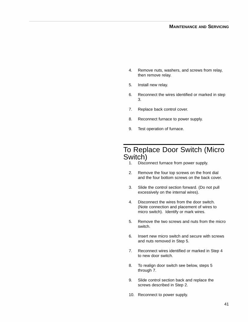
4. Remove nuts, washers, and screws from relay,then remove relay.
5. Install new relay.
6. Reconnect the wires identified or marked in step3.
7. Replace back control cover.
8. Reconnect furnace to power supply.
9. Test operation of furnace.
To Replace Door Switch (MicroSwitch)
1. Disconnect furnace from power supply.
2. Remove the four top screws on the front dialand the four bottom screws on the back cover.
3. Slide the control section forward. (Do not pullexcessively on the internal wires).
4. Disconnect the wires from the door switch.(Note connection and placement of wires tomicro switch). Identify or mark wires.
5. Remove the two screws and nuts from the microswitch.
6. Insert new micro switch and secure with screwsand nuts removed in Step 5.
7. Reconnect wires identified or marked in Step 4to new door switch.
8. To realign door switch see below, steps 5through 7.
9. Slide control section back and replace thescrews described in Step 2.
10. Reconnect to power supply.
41
MAINTENANCE AND SERVICING
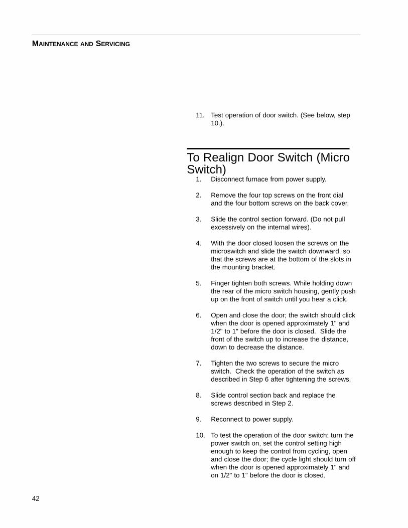
11. Test operation of door switch. (See below, step10.).
To Realign Door Switch (MicroSwitch)
1. Disconnect furnace from power supply.
2. Remove the four top screws on the front dialand the four bottom screws on the back cover.
3. Slide the control section forward. (Do not pullexcessively on the internal wires).
4. With the door closed loosen the screws on themicroswitch and slide the switch downward, sothat the screws are at the bottom of the slots inthe mounting bracket.
5. Finger tighten both screws. While holding downthe rear of the micro switch housing, gently pushup on the front of switch until you hear a click.
6. Open and close the door; the switch should clickwhen the door is opened approximately 1" and1/2" to 1" before the door is closed. Slide thefront of the switch up to increase the distance,down to decrease the distance.
7. Tighten the two screws to secure the microswitch. Check the operation of the switch asdescribed in Step 6 after tightening the screws.
8. Slide control section back and replace thescrews described in Step 2.
9. Reconnect to power supply.
10. To test the operation of the door switch: turn thepower switch on, set the control setting highenough to keep the control from cycling, openand close the door; the cycle light should turn offwhen the door is opened approximately 1" andon 1/2" to 1" before the door is closed.
42
MAINTENANCE AND SERVICING
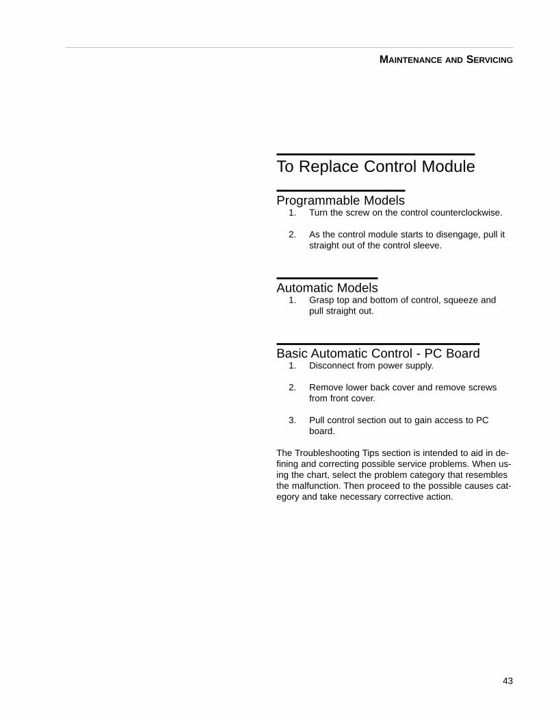
To Replace Control Module
Programmable Models1. Turn the screw on the control counterclockwise.
2. As the control module starts to disengage, pull itstraight out of the control sleeve.
Automatic Models1. Grasp top and bottom of control, squeeze and
pull straight out.
Basic Automatic Control - PC Board1. Disconnect from power supply.
2. Remove lower back cover and remove screwsfrom front cover.
3. Pull control section out to gain access to PCboard.
The Troubleshooting Tips section is intended to aid in de-fining and correcting possible service problems. When us-ing the chart, select the problem category that resemblesthe malfunction. Then proceed to the possible causes cat-egory and take necessary corrective action.
43
MAINTENANCE AND SERVICING

PROBLEM PROBABLE CAUSE CORRECTIVE ACTION
The power light does not illuminate. The furnace is not connected Check furnace connection
to power supply. to power source.
ON and OFF power switch is Replace power switch.
defective.
Fuses blown. Replace fuses.
The furnace does not heat,
cycle light illuminated. Heating elements burned out or Replace heating elements or
improper connections. repair connections.
The furnace does not heat, No power. Check power source and fuses or
cycle light not illuminated. breakers.
Two or more heating elements in Replace defective elements.
208V or 240V furnaces are burned
out.
Thermocouple has oxidized and Replace thermocouple.
opened the circuit. Indicated by:
a) basic automatic control - 1-5
degrees on display
b) automatic control - “OR” on
display.
c) Prog. 2 ramp & 2 dwell -
“SNB” on display.
d) Prog. 8 ramp & 8 dwell -
“OR” on display.
Defective electrical hookup. Repair electrical hookup.
Set point set too low. Reset set point to a higher value.
High power limit set to a low level. Reset level to a higher value.
Door switch malfunction. Re-align or replace door safety switch.
Defective mechanical door switch Replace relay.
relay coil or contacts.
44
Troubleshooting
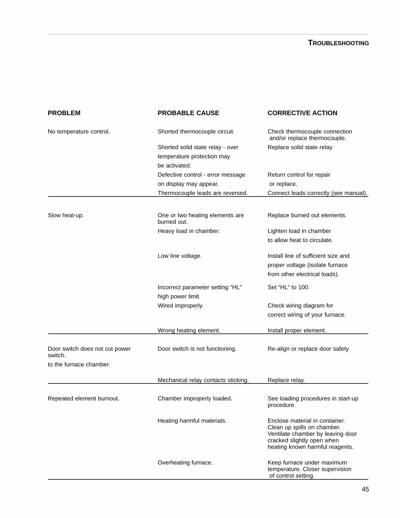
PROBLEM PROBABLE CAUSE CORRECTIVE ACTION
No temperature control. Shorted thermocouple circuit. Check thermocouple connectionand/or replace thermocouple.
Shorted solid state relay - over Replace solid state relay.
temperature protection may
be activated.
Defective control - error message Return control for repair
on display may appear. or replace.
Thermocouple leads are reversed. Connect leads correctly (see manual).
Slow heat-up. One or two heating elements are Replace burned out elements.burned out.
Heavy load in chamber. Lighten load in chamber
to allow heat to circulate.
Low line voltage. Install line of sufficient size and
proper voltage (isolate furnace
from other electrical loads).
Incorrect parameter setting “HL” Set “HL” to 100.
high power limit.
Wired improperly. Check wiring diagram for
correct wiring of your furnace.
Wrong heating element. Install proper element.
Door switch does not cut power Door switch is not functioning. Re-align or replace door safetyswitch.
to the furnace chamber.
Mechanical relay contacts sticking. Replace relay.
Repeated element burnout. Chamber improperly loaded. See loading procedures in start-up procedure.
Heating harmful materials. Enclose material in container. Clean up spills on chamber. Ventilate chamber by leaving door cracked slightly open when heating known harmful reagents.
Overheating furnace. Keep furnace under maximumtemperature. Closer supervisionof control setting.
45
TROUBLESHOOTING
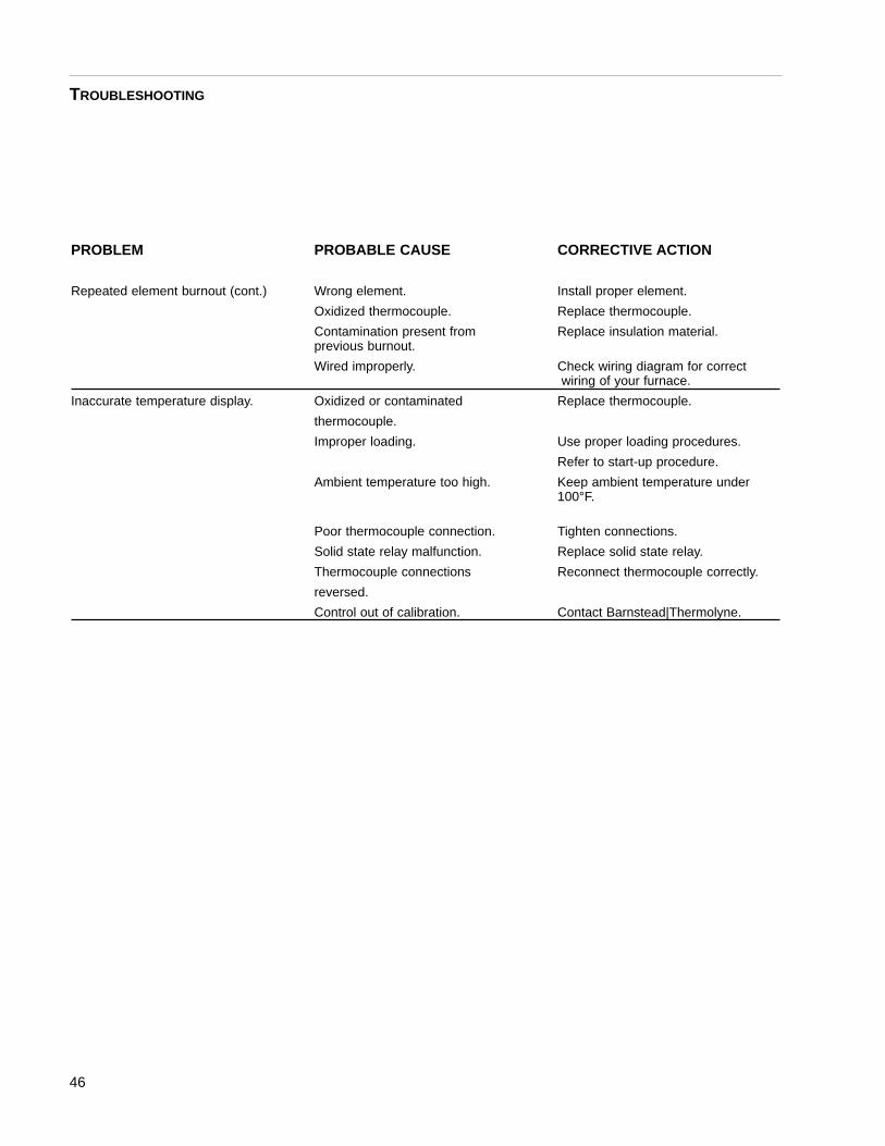
PROBLEM PROBABLE CAUSE CORRECTIVE ACTION
Repeated element burnout (cont.) Wrong element. Install proper element.
Oxidized thermocouple. Replace thermocouple.
Contamination present from Replace insulation material.previous burnout.
Wired improperly. Check wiring diagram for correctwiring of your furnace.
Inaccurate temperature display. Oxidized or contaminated Replace thermocouple.
thermocouple.
Improper loading. Use proper loading procedures.
Refer to start-up procedure.
Ambient temperature too high. Keep ambient temperature under 100°F.
Poor thermocouple connection. Tighten connections.
Solid state relay malfunction. Replace solid state relay.
Thermocouple connections Reconnect thermocouple correctly.
reversed.
Control out of calibration. Contact Barnstead|Thermolyne.
46
TROUBLESHOOTING

SERIES 1060Listed below is the common replacement parts for all models of the 6000 furnace. The far left column con-tains the letter designation found on the circuit diagrams. Be sure to identify the correct part number withrespect to the exact model number found on your furnace.
REPLACEMENT PART DESCRIPTION MODELS USED ON
PC750X4A Control Unit - PC Board F6018
PC750X2A Control Unit - PC Board F6010, F6010-33
CN71X63 Control Unit, Automatic F6020C, (-33), (-33-60) & (-60), F6028C & (-60)
CN71X56 Multi-Control Unit, Prog. (16 segment)
PLX82 Pilot Light All models except F6010, F6010-33, F6018
EL408X1 Heating Element, Top F6020C , (-33), (-33-60), (-33-80), (-33-60-80),(-60), (-60-80) & (-80), F6030CM, (-33),
(-33-60) & (-60)
EL408X10` Heating Element, Top F6010, F6010-33, F6018
EL408X2 Heating Element, Top F6028C, (-60), (-60-80) & (-80),
F6038CM & (-60)
EL408X5 Heating Element, bottom F6020C , (-33), (-33-60), (-33-80), (-33-60-80), (-60), (-60-80) & (-80), F6030CM, (-33),
(-33-60) & (-60)
EL408X4 Heating Element, bottom F6028C, (-60), (-60-80) & (-80),
F6038CM & (-60)
EL408X9 Heating Element, bottom F6010, F6010-33, F6018
EL205X6 Heating Element, side F6020C , (-33), (-33-60), (-33-80), (-33-60-80),
(-60), (-60-80) & (-80), F6030CM, (-33), (-33-60) & (-60)
EL408X3 Heating Element, side F6028C, (-60), (-60-80) & (-80), F6038CM
& (-60)
EL408X11 Heating Element, side F6010, F6010-33, F6018
FZX28 Fuse, Type ABC, 250 Volt, F6010-33
15 Amp
RYX57 Relay All models except F6010, F6010-33, F6018
RYX34 Solid State Relay All models except F6010, F6010-33, F6018
RYX54 Solid State Relay F6010, F6010-33, F6018
SWX144 Power Switch All models
SW356X1A Micro Switch All models
TC357X1A Thermocouple, Type K F6010, F6010-33, F6018
TC408X1A Thermocouple, Type F All models except F6010, F6010-33, F6018
SW745X1A Push To Set Temp. Switch F6010, F6010-33, F6018
RS745X1A Temp. Adjustment Rheostat F6010, F6010-33, F6018
CAX94 Filter, EMI F6010-33
CAX99 Filter, EMI F6020C-33, (-33-60), (-33-60-80) & (-33-80), F6030CM-33 & (-33-60)
47
Replacement Parts List
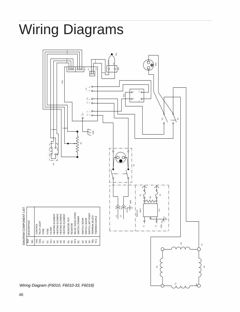
48
Wiring Diagrams
R1
HE
AT
ING
ELE
ME
NT
HE
AT
ING
ELE
ME
NT
SW
ITC
H, S
ET
PO
INT
HE
AT
ING
ELE
ME
NT
RE
LAY,
SO
LID
STA
TE
HE
AT
ING
ELE
ME
NT
RE
SIS
TO
R, P
OT
RE
SIS
TO
R
TH
ER
MO
CO
UP
LE
TE
RM
INA
L B
LOC
K
SW
ITC
H, D
OO
R
SW
ITC
H, D
OO
R
SW
ITC
H, P
OW
ER
PIL
OT
LIG
HT
DE
SC
RIP
TIO
N
R2
S4
TC
1
TB
1
S3
S2
S1
RY
1
RE
F.
R1
H4
H3
F2
F1
FL1
H2
H1
DS
1
CN
1
NO
.
FU
SE
FU
SE
FIL
TE
R
CO
NT
RO
L
H3
H2
H4
T2
T1
H1
DIA
GR
AM
CO
MP
ON
EN
T L
IST
ON
LY
F60
10-3
3
L1 L2
GN
DF
L1
R2
F1
F2
L2L1
GN
D
S1S
4
S2
YE
LLO
W
J1J3
J8J5
J2+
J9
S3
GN
D
3 +
4
21
DS
1
RY
1
TB
1
RE
D-J4
RE
D
HI
AC
AC
J7 GN
D
+LO
W-
SS
R
CN
1
YE
L.
J6
TC
1
Wiring Diagram (F6010, F6010-33, F6018)
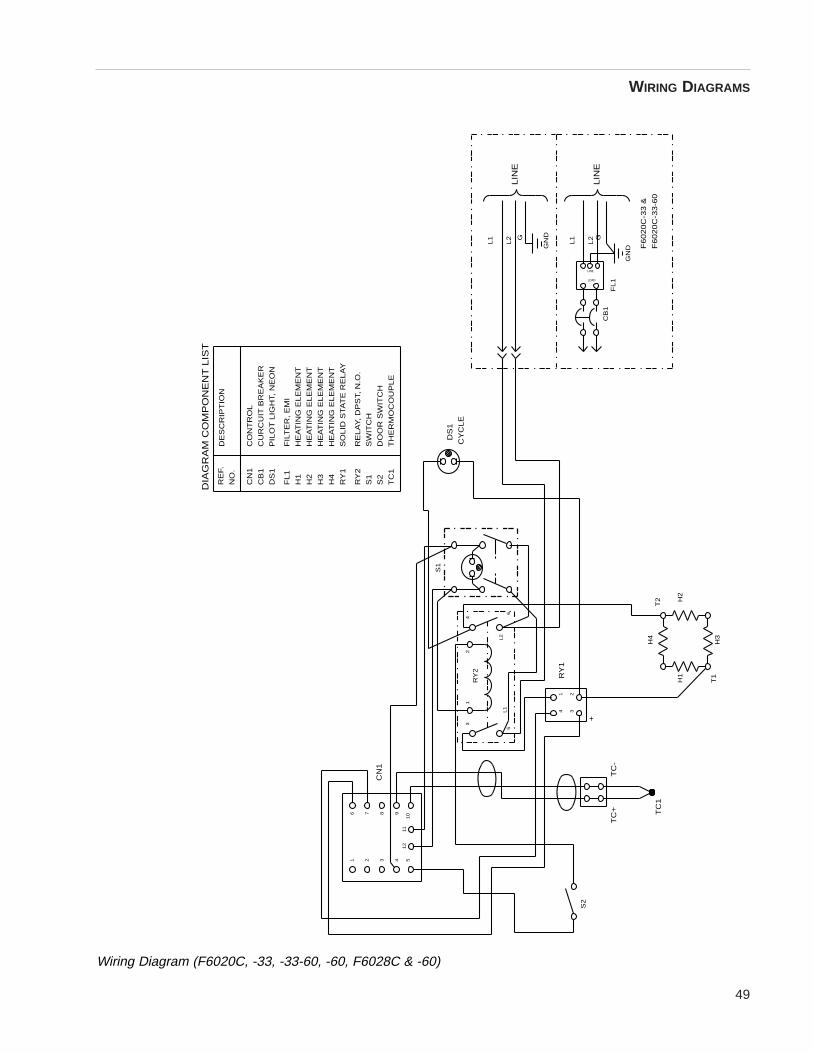
49
WIRING DIAGRAMS
DIA
GR
AM
CO
MP
ON
EN
T L
IST
F6
02
0C
-33
&
F6
02
0C
-33
-60
S2
TC
1
T1
H1
H3
H4
T2 H
2
RY
2
RE
F.
L1
TC
+
5
TC
-
+
34
1112
8
1097
3 542
CN
1
3
L2
21R
Y1
6
21
RY
2
S1
4
TC
1
S2
S1
61
H4
H3
CB
1
FL
1
NO
.
RY
1
H2
H1
DS
1
CN
1
TH
ER
MO
CO
UP
LE
DO
OR
SW
ITC
H
RE
LA
Y,
DP
ST,
N.O
.
SW
ITC
H
DS
1
CY
CL
E
CB
1
GN
D
L2
L2
L1
FL1
G G
LOAD
LINE
GN
D
L1
HE
AT
ING
EL
EM
EN
T
HE
AT
ING
EL
EM
EN
T
CU
RC
UIT
BR
EA
KE
R
FIL
TE
R,
EM
I
DE
SC
RIP
TIO
N
PIL
OT
LIG
HT,
NE
ON
HE
AT
ING
EL
EM
EN
T
HE
AT
ING
EL
EM
EN
T
SO
LID
STA
TE
RE
LA
Y
CO
NT
RO
L
LIN
E
LIN
E
Wiring Diagram (F6020C, -33, -33-60, -60, F6028C & -60)
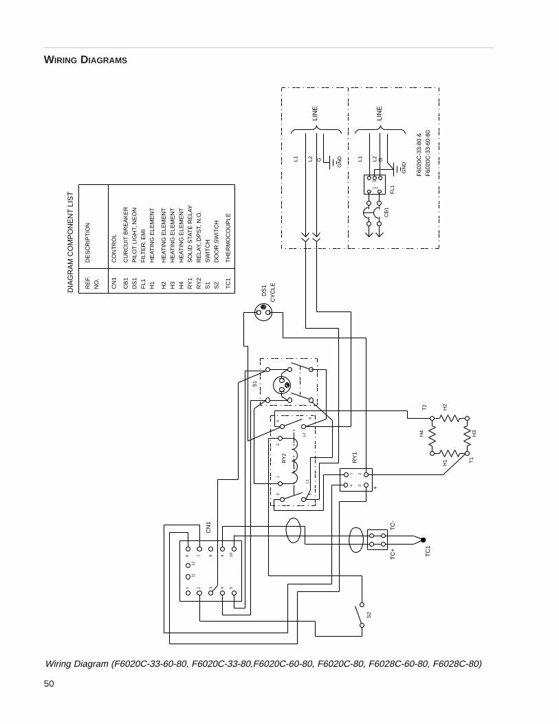
50
WIRING DIAGRAMS
F60
20C
-33-
60-8
0
DIA
GR
AM
CO
MP
ON
EN
T L
IST
F60
20C
-33-
80 &
S2
TC
1
T1
H1
H3
H4
T2
H2
L1
TC
+
5
TC
-
+34
CN
1
1211
8 1097
3 542
31
L2
6
21R
Y1
2
RY
24
S1
TC
1
S2
S1
RY
2
61
H4
H3
CB
1
FL1
NO
.
RE
F.
RY
1
H2
H1
DS
1
CN
1
TH
ER
MO
CO
UP
LE
DO
OR
SW
ITC
H
RE
LAY,
DP
ST,
N.O
.
SW
ITC
H
DS
1
CY
CLE
FL1
CB
1
GN
DL2 L2L1G G
LOAD
LINE
GN
D
L1
HE
AT
ING
ELE
ME
NT
HE
AT
ING
ELE
ME
NT
CU
RC
UIT
BR
EA
KE
R
FIL
TE
R, E
MI
DE
SC
RIP
TIO
N
PIL
OT
LIG
HT,
NE
ON
HE
AT
ING
ELE
ME
NT
HE
AT
ING
ELE
ME
NT
SO
LID
STA
TE
RE
LAY
CO
NT
RO
L
LIN
E
LIN
E
Wiring Diagram (F6020C-33-60-80, F6020C-33-80,F6020C-60-80, F6020C-80, F6028C-60-80, F6028C-80)
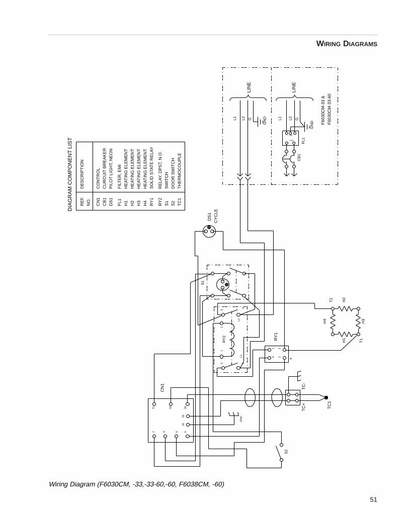
51
WIRING DIAGRAMS
TC
1
GN
D
S2
TC
+
33 2625
18
3 65
311
F60
30C
M-3
3 &
H3
H4
T1
H1
T2
H2
F60
30C
M-3
3-60
HE
AT
ING
ELE
ME
NT
HE
AT
ING
ELE
ME
NT
CU
RC
UIT
BR
EA
KE
R
TH
ER
MO
CO
UP
LE
FIL
TE
R, E
MI
DE
SC
RIP
TIO
N
PIL
OT
LIG
HT,
NE
ON
HE
AT
ING
ELE
ME
NT
DO
OR
SW
ITC
H
RE
LAY,
DP
ST,
N.O
.
HE
AT
ING
ELE
ME
NT
SO
LID
STA
TE
RE
LAY
L2L1 +
TC
-
5
21
34R
Y1
CN
1
32
1R
Y2
6
TC
1
S2
S1
RY
2
S1
4
SW
ITC
H
H4
H3
CB
1
FL1
NO
.
RE
F.
RY
1
H2
H1
DS
1
CN
1C
ON
TR
OL
CB
1
DS
1
CY
CLE
GN
DL2 L2L1
FL1
G G
LOAD
LINE
GN
D
LIN
E
LIN
E
L1
DIA
GR
AM
CO
MP
ON
EN
T L
IST
Wiring Diagram (F6030CM, -33,-33-60,-60, F6038CM, -60)
52
Ordering Procedures
Please refer to the Specification Plate for the complete model number, serial number, and series numberwhen requesting service, replacement parts or in any correspondence concerning this unit.
All parts listed herein may be ordered from the Barnstead|Thermolyne dealer from whom you purchased thisunit or can be obtained promptly from the factory. When service or replacement parts are needed we ask thatyou check first with your dealer. If the dealer cannot handle your request, then contact our Customer ServiceDepartment at 319-556-2241 or 800-553-0039.
Prior to returning any materials to Barnstead|Thermolyne Corp., please contact our Customer ServiceDepartment for a “Return Goods Authorization” number (RGA). Material Returned without an RGA number willbe returned.
53
Barnstead|Thermolyne Corporation warrants that if a product manufactured byBarnstead|Thermolyne and sold by it within the continental United States or Canadaproves to be defective in material or construction, it will provide you, without charge, for aperiod of ninety (90) days, the labor, and a period of two (2) years, the parts, necessary toremedy any such defect. Outside the continental United States and Canada, the warrantyprovides, for two (2) years, the parts necessary to remedy any such defect. The warrantyperiod shall commence either six (6) months following the date the product is sold byBarnstead|Thermolyne or on the date it is purchased by the original retail consumer,whichever date occurs first.
All warranty inspections and repairs must be performed by and parts obtained from anauthorized Barnstead|Thermolyne dealer or Barnstead|Thermolyne (at its own discre-tion). Heating elements, however, because of their susceptibility to overheating and contam-ination, must be returned to our factory, and if, upon inspection, it is concluded that failure isnot due to excessive high temperature or contamination, warranty replacement will be pro-vided by Barnstead|Thermolyne . The name of the authorized Barnstead|Thermolynedealer nearest you may be obtained by calling 1-800-446-6060 (319-556-2241) or writingto:
Barnstead|ThermolyneP.O. Box 797
2555 Kerper BoulevardDubuque, IA 52004-0797
USAFAX: (319) 589-0516
E-MAIL ADDRESS: [email protected]
Barnstead|Thermolyne’ s sole obligation with respect to its product shall be to repair or(at its own discretion) replace the product. Under no circumstances shall it be liable for inci-dental or consequential damage.
THE WARRANTY STATED HEREIN IS THE SOLE WARRANTY APPLICABLE TOBarnstead|Thermolyne PRODUCTS. Barnstead|Thermolyne EXPRESSLY DISCLAIMSANY AND ALL OTHER WARRANTIES, EXPRESSED OR IMPLIED, INCLUDINGWARRANTIES OF MERCHANTABILITY OR FITNESS FOR USE.
Two Year Limited Warranty

54

55
