tx ii transmitter - instrumentation gdd · transmitter in this state until the led turns off to let...
TRANSCRIPT
IP Transmitter
Model TxII 5000W-2400V-15A
Instruction Manual
860 boul. de la Chaudière, suite 200
Québec (Qc), Canada, G1X 4B7
Tel.: +1 (418) 877-4249
Fax: +1 (418) 877-4054
E-Mail: [email protected]
Web site: www.gdd.ca

Instrumentation GDD Inc. 2016-02-29 Page 2
Visit our web site at:
WWW.GDD.CA
To:
Discover GDD’s new products.
Download the latest version of the Instruction Manual.
Comment on or ask questions about products.
Instrumentation GDD Inc. 2016-02-29 Page 3
1. INTRODUCTION ................................................................................................................................................ 4
2. SAFETY ............................................................................................................................................................. 4
3. TRANSMITTER DESCRIPTION ............................................................................................................................ 5
3.1 EQUIPMENT LIST ............................................................................................................................................... 5 3.2 TRANSMITTER COMPONENTS ................................................................................................................................ 5
3.2.1 Output Terminals ................................................................................................................................. 5 3.2.2 Power Cable ........................................................................................................................................ 6 3.2.3 Serial number ...................................................................................................................................... 6 3.2.4 1.0X / 1.5X MODE Switch ..................................................................................................................... 7 3.2.5 Master-Slave Interface......................................................................................................................... 7 3.2.6 Status LEDs .......................................................................................................................................... 7 3.2.7 Current Display .................................................................................................................................... 7 3.2.8 Vent Pipes ........................................................................................................................................... 7 3.2.9 Ohmmeter and Wattmeter Display ...................................................................................................... 8 3.2.10 Cancel O.L.P. Button (open loop protection)..................................................................................... 8 3.2.11 High Voltage Indicator .................................................................................................................... 8 3.2.12 Turbo Switch ................................................................................................................................... 8 3.2.13 Time Base / DC Selector................................................................................................................... 8 3.2.14 Warning LEDs ................................................................................................................................. 9 3.2.15 Voltage Selector .............................................................................................................................. 9 3.2.16 Power switch: ON / OFF ................................................................................................................ 10 3.2.17 Emergency Stop ............................................................................................................................ 10 3.2.18 Circuit Breaker .............................................................................................................................. 10
4. TRANSMITTER OPERATION ............................................................................................................................. 11
4.1 STEPS TO FOLLOW ............................................................................................................................................... 11 4.2 OUTPUT POWER ................................................................................................................................................. 11
5. GENERATOR CONNECTION .................................................................................................................................. 12
5.1 SINGLE PHASE CONNECTION ................................................................................................................................... 12 5.2 THREE PHASES BASICS .......................................................................................................................................... 12 5.3 TRANSMITTER CONNECTION TO A THREE PHASE GENERATOR .......................................................................................... 12
6. MASTER / SLAVE MODE ...................................................................................................................................... 14
7. TROUBLESHOOTING ............................................................................................................................................ 16
8. TECHNICAL HELP ................................................................................................................................................. 19
9. SPECIFICATIONS .................................................................................................................................................. 20
10.GLOSSARY ........................................................................................................................................................... 21
TABLE OF CONTENTS

Instrumentation GDD Inc. 2016-02-29 Page 4
The GDD 5000W IP Transmitter, model TxII, is used for time-domain induced polarization surveys. Its transmission cycle is 2 seconds ON, 2 seconds OFF. Other timings are available. It is sturdy and can operate in extreme climatic conditions (40oC to 65oC). The GDD 5000W-2400V-15A IP Transmitter can be powered directly from a 240 VAC power source, such as a portable regulated generator. The TxII transmits up to 15 A in a highly conductive ground or sends up to 2400V in a resistive ground for a total power of 5000W. The GDD TxII is easy to use. And it automatically stops within microseconds if a short circuit occurs or if the circuit opens. There is also an emergency stop button that shuts down completely and quickly all power inside the transmitter. However and for user safety, we strongly recommend always wearing electrically insulated shoes and gloves while operating the transmitter.
Safety hints:
Wear electrically insulated shoes. They should be approved by a certifying organization (CSA, ANSI) i.e. marked with the logo:
Wear electrically insulated gloves rated class 1 (7.5 kV).
1. INTRODUCTION
2. SAFETY

Instrumentation GDD Inc. 2016-02-29 Page 5
3.1 Equipment list
When receiving a GDD 5000W-2400V-15A IP Transmitter, model TxII, ensure that it contains the following elements:
One (1) TxII Transmitter built in a transportation box from Pelican.
One (1) 20A power cable.
One (1) 20/30A cable adaptor.
One (1) GDD Instruction manual.
One (1) GDD Safe operating procedures (SOP).
One (1) GDD blue carrying case.
Optional
GDD Master-Slave yellow cable.
Do not hesitate to communicate with GDD Instrumentation Inc. if needed.
3.2 Transmitter components
In this section, the TxII components from the control panel are shown, named and explained (see the picture on the next page).
3.2.1 Output Terminals This is where the wires from the electrodes are connected. Press the button over each terminal to insert wires. Be careful, the terminals can reach up to 2400V.
3. TRANSMITTER DESCRIPTION

Instrumentation GDD Inc. 2016-02-29 Page 6
3.2.2 Power Cable The end of the power cable can be plugged into any 220-240 VAC / 50-60 Hz voltage source. Please check transmitter’s nameplate for specificity. 3.2.3 Serial number
Each instrument has its own serial number to identify it.
7- Current
Display
9- Ohmmeter
/ Wattmeter
Display
12- Turbo
Switch
15- Voltage
Selector
10- Cancel
Open Loop
button
18- Circuit
Breaker
16- Power Switch:
ON / OFF
6- Status
LEDs
14-
Warning
LEDs
3- Serial
Number
13- Time
Base / DC
Selector
8- Vent
Pipe
2- Power
Cable
1- Output
Terminals
5- Master-Slave
Interface
4- 1.0X / 1.5X
MODE Switch
8- Vent Pipe
with filter
17- Emergency
stop
11- High voltage
indicator
Instrumentation GDD Inc. 2016-02-29 Page 7
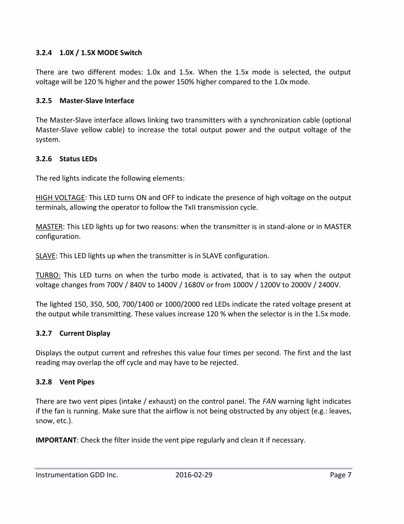
3.2.4 1.0X / 1.5X MODE Switch
There are two different modes: 1.0x and 1.5x. When the 1.5x mode is selected, the output voltage will be 120 % higher and the power 150% higher compared to the 1.0x mode.
3.2.5 Master-Slave Interface The Master-Slave interface allows linking two transmitters with a synchronization cable (optional Master-Slave yellow cable) to increase the total output power and the output voltage of the system.
3.2.6 Status LEDs The red lights indicate the following elements: HIGH VOLTAGE: This LED turns ON and OFF to indicate the presence of high voltage on the output terminals, allowing the operator to follow the TxII transmission cycle. MASTER: This LED lights up for two reasons: when the transmitter is in stand-alone or in MASTER configuration. SLAVE: This LED lights up when the transmitter is in SLAVE configuration. TURBO: This LED turns on when the turbo mode is activated, that is to say when the output voltage changes from 700V / 840V to 1400V / 1680V or from 1000V / 1200V to 2000V / 2400V. The lighted 150, 350, 500, 700/1400 or 1000/2000 red LEDs indicate the rated voltage present at the output while transmitting. These values increase 120 % when the selector is in the 1.5x mode. 3.2.7 Current Display Displays the output current and refreshes this value four times per second. The first and the last reading may overlap the off cycle and may have to be rejected. 3.2.8 Vent Pipes There are two vent pipes (intake / exhaust) on the control panel. The FAN warning light indicates if the fan is running. Make sure that the airflow is not being obstructed by any object (e.g.: leaves, snow, etc.). IMPORTANT: Check the filter inside the vent pipe regularly and clean it if necessary.

Instrumentation GDD Inc. 2016-02-29 Page 8
3.2.9 Ohmmeter and Wattmeter Display GROUND RESISTANCE: It displays the ground resistance when the generator is plugged in; the power switch is in STOP position (down) and the emergency button is pulled up. The value shown is the contact resistance in kilo-ohms (x1000Ω). OUTPUT POWER: When the transmitter is transmitting, the output power expressed in Watt is indicated instead of the contact resistance. 3.2.10 Cancel O.L.P. Button (open loop protection) The GDD TxII has an internal open loop protection circuit to prevent direct electric shock to the operator. This protection is triggered when the electrodes are not connected to the output terminals, or when the current is less than 30 mA. NOTE: If the ground has a very high resistivity, the open loop protection could disrupt the signal's transmission. To temporarily cancel the O.L.P. turn the TxII OFF, press and hold the Cancel O.L.P. button and turn the TxII ON.
3.2.11 High Voltage Indicator This LED turns ON and OFF to indicate the presence of high voltage on the output terminals, allowing the operator to follow the TxII transmission cycle.
3.2.12 Turbo Switch All voltage scales above 1200V can be set with the Turbo switch. This switch allows reaching the 1400 V / 1680V or 2000V / 2400V scales while the voltage selector is in the 700V / 840V or 1000V / 1200V position. NOTE: It may take up to 4 seconds before the Turbo turns ON or OFF.
3.2.13 Time Base / DC Selector The time base selector allows the following modes: DC, 1s, 2s, 4s, 8s and 16s. The DC switch allows the transmitter to work as a DC voltage source. To do so, place the DC switch to the left and the transmitter will work in DC mode. To select a different time base, place the DC switch to the right and select the desired time base by turning the rotary.

Instrumentation GDD Inc. 2016-02-29 Page 9
3.2.14 Warning LEDs The red lights indicate the following problems: LOGIC FAIL: Caused by an internal electronic failure. LEAKAGE: This alarm is triggered when there is a synchronization problem (example: current detected through the unit during OFF time). OPEN LOOP: This alarm is triggered when there is infinite resistance between the two output terminals (the circuit is opened) or when the output current is less than 30 mA (highly resistive ground). OVER CURRENT: This alarm is triggered when the current limit is exceeded. The current limit is set to 10 A in normal mode and 5 A in DC mode. A.C. IN HIGH: High (≥ 290 VAC) or irregular voltage from the generator. An unregulated generator can trigger this alarm. The power transformer may overheat. A.C. IN LOW: Low (≤ 170 VAC) or irregular voltage from the generator. An unregulated generator can trigger this alarm. OVERHEATING: The internal temperature of the transmitter is too high (≥ 85°C). Leave the transmitter in this state until the LED turns off to let it cool off. FAN: The FAN indicator lights up when the fan is running. The fan starts to cool down the transmitter automatically when the temperature inside the transmitter is higher than 65°C. STOP TX: Indicates that the transmitter stopped transmitting. This LED lights up with the warning LEDs. POWER LIMIT: Indicates that the power limit has been exceeded. This limit is set to 5000W. POWER ON: Indicates that the transmitter is powered on. 3.2.15 Voltage Selector To set the output voltage, press and turn this selector to the right position. Pressing down this knob will stop the current transmission.

Instrumentation GDD Inc. 2016-02-29 Page 10
The available output voltages are:
1.0x mode: 150V, 350V, 500V, 700V, 1000V, 1400V and 2000V.
1.5x mode: 180V, 420V, 600V, 840V, 1200V, 1680V and 2400V.
3.2.16 Power Switch: ON / OFF To turn on the transmitter, lift the switch guard and toggle the switch in the START position (up). Toggle the switch in the STOP position (down) to turn off the transmitter. Pushing down the switch guard will also toggle the power switch in the STOP position. If the transmitter is OFF but still powered (emergency button pulled up), the ground resistance will be measured (see 3.2.9 – Ohmmeter and wattmeter display).
3.2.17 Emergency Stop
This button is a safety mechanism and must be used in an emergency situation. The emergency stop shuts down all power inside the transmitter and all functions are disabled including the measurement of the ground resistance. Once the emergency stop has been pushed down, three (3) conditions must be met to reset the transmitter and make it work normally :
The transmitter must be powered by an external supply.
The emergency stop button must be pulled up.
The power switch must be in STOP position (down). Once these three (3) steps have been done, turn on the transmitter using the power switch.
3.2.18 Circuit Breaker There is a built-in circuit breaker to protect the instrument from overloading.

Instrumentation GDD Inc. 2016-02-29 Page 11
4.1 Steps to follow
Here are the basic steps to operate a TxII in stand-alone mode:
1. Make sure that the TxII is turned OFF.
2. Drive the electrodes into the ground and connect them to the output terminals with insulated wires.
3. Start the generator.
4. Reset the emergency stop circuit (see section 3.2.17 - Emergency Stop).
5. Put the voltage selector on the lowest voltage scale (150V), turn the 1.0X / 1.5X
switch to 1.0x mode and turn the transmitter ON .
6. Increase the output voltage to increase the output power. It is not necessary to turn off the transmitter to change the voltage scale or select a different time base. The 1.5x mode allows reaching an intermediate output power. Note that the transmitter will automatically stop if you try to transmit more than 5000W. In this case, select a lower voltage scale and turn the transmitter OFF and ON again to reset the STOP TX alarm.
IMPORTANT:
Turn the transmitter OFF only when the “HIGH VOLTAGE” LED is off, which occurs in the OFF time of the cycle or when the STOP TX light is triggered.
Turn the transmitter OFF before shutting down the generator.
4.2 Output Power
If a generator more powerful than 5000W is used, the output power will be limited to 5000W by the TxII. If the generator used cannot deliver up to 5000W, such as a 700W generator, the output power will be limited by the generator.
4. TRANSMITTER OPERATION

Instrumentation GDD Inc. 2016-02-29 Page 12
5. GENERATOR CONNECTION
5.1 Single Phase Connection
The transmitter is intended to be powered from a single phase generator. The rated input voltage is 240VAC. The following picture shows the wiring diagram of the power cable. Note that the polarity of the connection is not important.
5.2 Three Phases Basics
The types of three phase configurations are Delta (Δ) and Star (Υ):
N
Delta and Star three phase connection
The star configuration might have a neutral connection. However the delta configuration doesn’t have a neutral connection. There is a √3 factor between the line to line voltage and the line to neutral voltage - i.e. for a 230VLN generator, the line to line voltage would be 400VLL.
5.3 Transmitter Connection to a three Phase Generator
Damages due to a bad connection to a three phase generator will not be covered by the warranty.
Y
WG
X
L14-20PTO GENERATOR
WXYG
125V/250V 20A MALE
WHITE
BLACK

Instrumentation GDD Inc. 2016-02-29 Page 13
As the rated input voltage of the transmitter is 240VAC, precautions must be taken when connecting to a three phase generator. The following connection diagram is provided for a 400VLL generator. Only a generator which has a neutral connection available can be used with the transmitter. The line-neutral voltage is 230VAC. Make sure not to connect the transmitter to a line to line connection. Bad connections could damage the instrument. Do not use the ground connection instead of the neutral. If two transmitters are going to be used, an additional line to neutral connection can be made with a different phase. Note that the polarity of the connection is not important.
PH1
PH2
PH3
NEUTRAL
GENERATORTRANSMITTER TRANSMITTER

Instrumentation GDD Inc. 2016-02-29 Page 14
Here are the basic steps for a Master/Slave operation of the TxII:
1. Connect the yellow synchronization cable (Master/Slave) to the transmitters. The
Master/Slave cable terminations are different: one is labeled MASTER and the other one SLAVE. The transmitter is MASTER or SLAVE according to the termination of the cable connected on its interface. The MASTER and SLAVE LEDs indicate the mode of each transmitter. (see figure 2, yellow line)
2. Connect an insulated wire between the terminal (A) of one transmitter and the terminal (B)
of the other one. (see figure 2, blue line) 3. Connect the two power cables from the transmitters to the generator. (see figure 2, red
lines) 4. Drive the electrodes into the ground and connect them to the unused terminals (A) and (B)
by using insulated wires. (see figure 2, blue lines)
Power cables
Yellow
Master-Slave
cable
Wires
6. MASTER / SLAVE MODE
Instrumentation GDD Inc. 2016-02-29 Page 15
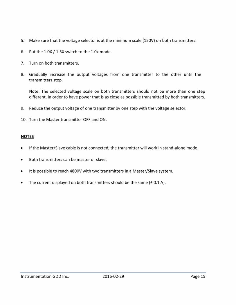
5. Make sure that the voltage selector is at the minimum scale (150V) on both transmitters. 6. Put the 1.0X / 1.5X switch to the 1.0x mode. 7. Turn on both transmitters. 8. Gradually increase the output voltages from one transmitter to the other until the
transmitters stop.
Note: The selected voltage scale on both transmitters should not be more than one step different, in order to have power that is as close as possible transmitted by both transmitters.
9. Reduce the output voltage of one transmitter by one step with the voltage selector. 10. Turn the Master transmitter OFF and ON.
NOTES
If the Master/Slave cable is not connected, the transmitter will work in stand-alone mode.
Both transmitters can be master or slave.
It is possible to reach 4800V with two transmitters in a Master/Slave system.
The current displayed on both transmitters should be the same (± 0.1 A).

Instrumentation GDD Inc. 2016-02-29 Page 16
With a good understanding of the transmitting circuit and a little logic, most of the problems that will happen with the TxII can often be resolved.
1- Nothing seems to work The ON LED doesn’t light up and the display remains blank: check if the power source (generator) is working properly. Check also the power cable and the extension cord. The breaker might also be triggered.
2- The ON LED lights up but the TxII does not transmit First, check if the voltage selector is not pressed down. Then check which warning LEDs also light up: LOGIC FAIL: Indicates that an internal electronic failure occurred. Turn the TxII OFF and ON. If it doesn’t work, move the TxII away from the current electrodes. LEAKAGE: Turn the TxII OFF and ON. If it doesn’t work, move the TxII away from the current electrodes. Note: False alarms can also occur in some cases such as a poorly regulated generator, a low supply voltage or, in some unlikely cases, proximity of the transmitter to the electrodes. False alarms can also be possible on a highly chargeable ground where the discharge is very slow, leading to a non zero value during the whole OFF time. If this is the case, the remaining discharge voltage in the ground could potentially trigger the leakage alarm of the transmitter by injecting a small current in the TX when the output polarity reverses at the end of the OFF time.
OPEN LOOP: Can be caused by a cut wire or by highly resistive ground. In such a case, you can bypass the open loop protection with the Cancel O.L.P. switch. OVER CURRENT: The output current is too high. Reduce the output voltage or pull the electrodes out of the ground a bit. A.C. IN (HIGH or LOW): Indicates that the power source (generator) is defective. The supply voltage must be stable and between 170 VAC and 290 VAC. Try to transmit less power with the TxII or change to another kind of generator.
WARNING: Always use a regulated generator. An unregulated generator could damage the instrument which would then not be covered by the warranty.
7. TROUBLESHOOTING
Instrumentation GDD Inc. 2016-02-29 Page 17
OVERHEATING: Indicates that the internal temperature of the TxII is too high. Don’t turn the TxII OFF but leave it in this state to let the fan keep running to cool off the instrument. POWER LIMIT: Reduce the output voltage. STOP TX: This LED lights up when one of the previous problems is detected.
3- The TxII works well but the output power is very low
First, check if it is possible to increase the voltage. Every time you increase the voltage scale by one step, the output power is approximately doubled. It is therefore possible to send 3000W at a given scale (e.g.: 6000 mA at 500V) but the TxII will stop transmitting on the next higher scale (e.g.: 8400 mA at 700V) since it would try to transmit around 5880W. In such a case, try the 1.5x mode at the 500V scale in order to have an intermediate output power, e.g. around 4300W (7200 mA at 600V). You can also raise or lower the electrodes in the ground in order to alter the overall resistivity of the circuit. This could allow you to transmit 5000W at 700V.
4- Ground with very high resistivity
If the ground is highly resistive, it is possible that the output current is too low even at the maximum voltage. In such a case, you have to improve the electrode contact with the ground.
Here are a few suggestions:
Move the electrodes to get a better contact;
Double (or more) the number of electrodes;
Water the electrodes (with salt water if available).
5- Noise, Bad signal (Receiver)
The noise is an undesired interference or a disturbance that affects the signal.
The source of noise may be a second IP or EM transmitter operating in the area; the interference zone may be as wide as 10 kilometers, depending on the power of the instrument and the system used. If a recurrent signal is received while the transmitter is powered off, this is certainly due to a second transmitter. The receiver could even synchronize with the signal if compatible.

Instrumentation GDD Inc. 2016-02-29 Page 18
Telluric currents may also cause the noise: they occur naturally near the surface of the earth and concentrate in conductive zones such as overburdens, shale or graphite formations, etc. To continue the survey in spite of telluric currents, improve the electrode contacts and increase the output current of the transmitter in order to increase the signal-to-noise ratio. Finally, the noise may originate from a defective transmitter or receiver. First, check the electrodes, decrease the contact resistance and make sure there is no loose contact. The signal timings of the receiver and the transmitter must be the same. If necessary, take a reading at a preceeding station or repeat tests with another receiver or transmitter.

Instrumentation GDD Inc. 2016-02-29 Page 19
If you encounter a problem that can’t be fixed or that is not described in the troubleshooting section, or for any other particular information, do not hesitate to contact us: Instrumentation GDD Inc. Phone: +1 (418) 877-4249 Fax: +1 (418) 877-4054 Toll free line (for Canada): 1 (877) 977-4249 E-mail: [email protected] / [email protected]
Emergency (out of business hours):
Pierre Gaucher: Home tel.: (418) 657-5870 Mobile phone: (418) 261-5552 Régis Desbiens: Home tel.: (418) 658-8539 Mobile phone: (418) 570-3408
Any GDD TxII transmitter that breaks down while under warranty or service will be replaced free of charge upon request for the duration of repairs, subject to instruments availability, except for shipping charges. Although this service is subject to instrument availability, we have been able to honour this commitment until now.
8. TECHNICAL HELP
Instrumentation GDD Inc. 2016-02-29 Page 20
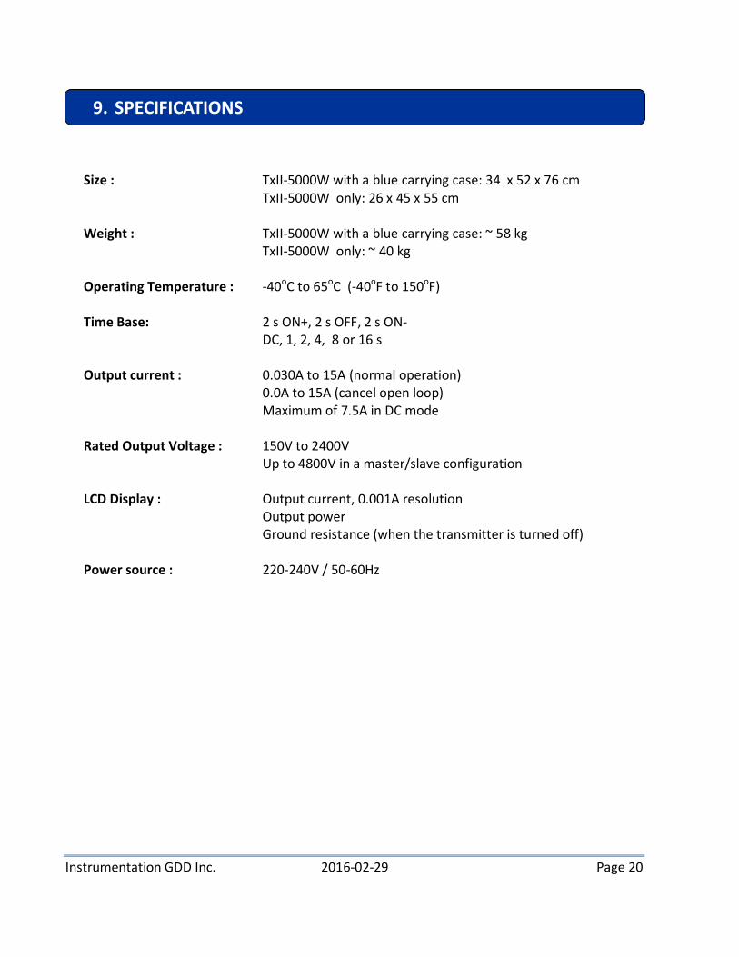
Size : TxII-5000W with a blue carrying case: 34 x 52 x 76 cm TxII-5000W only: 26 x 45 x 55 cm Weight : TxII-5000W with a blue carrying case: ~ 58 kg TxII-5000W only: ~ 40 kg Operating Temperature : -40oC to 65oC (-40oF to 150oF) Time Base: 2 s ON+, 2 s OFF, 2 s ON- DC, 1, 2, 4, 8 or 16 s Output current : 0.030A to 15A (normal operation)
0.0A to 15A (cancel open loop) Maximum of 7.5A in DC mode
Rated Output Voltage : 150V to 2400V Up to 4800V in a master/slave configuration LCD Display : Output current, 0.001A resolution Output power Ground resistance (when the transmitter is turned off)
Power source : 220-240V / 50-60Hz 1.
2.
3.
4.
5.
6.
9. SPECIFICATIONS

Instrumentation GDD Inc. 2016-02-29 Page 21
Induced polarisation (I.P.) is a geophysical technique: an electric current is induced into the ground and the voltage decay is monitored trough electrodes to measure its conductivity and chargeability. The GDD TxII is one of the principal components for an I.P. survey system.
Short circuit: Very low resistance connection between two nodes resulting in a faulty current. Transmitting circuit: The whole system associated with the TxII: wires, electrodes, ground and
transmitter. Open circuit: Infinite resistance between two nodes. It is the electrical opposite of a short circuit. Conductive ground: Ground with a low electrical resistivity. Such grounds are usually associated
with thick overburden and the presence of water (e.g.: a swamp). Resistive ground: Ground with a high electrical resistivity. Such grounds are usually associated
with bare rock or sand, with little overburden.
10. GLOSSARY