two-stage supercharging with a scroll-type … supercharging with a scroll-type supercharger and an...
TRANSCRIPT
Two-stage Supercharging with a Scroll-type Supercharger and an Exhaust Gas Turbocharger
The Handtmann scroll-type supercharger HSLn 580’s moment
of inertia is less than 20 % of that of a comparable compressor
system. Fitting it to a Ford 1.0 l EcoBoost engine in tandem with
a conventional turbocharger significantly improves drivability and
torque development.
INTRODUCTION
Downsizing is an effective and proven concept for reducing the fuel consump-tion of combustion engines. Downsized engines offer performance equivalent to those with larger cylinder capacities, but consume less fuel, especially in partial-load ranges. The essential pre-requisite for this is supercharging.
Today’s most common solution single-stage exhaust-gas turbocharging forces trade-offs between achievable performance, fuel consumption, and start-performance. The spontaneously available torque at start is reduced pro-portionally to the reduction in cylinder capacity. In addition, there is the typical “turbo lag” caused by the delayed
dynamic activation of the turbocharger. This all makes start-up performance one of the significant restrictive criteria in the design of a combustion engine.
Multi-stage supercharging, for exam-ple combining mechanical and turbo-charging, offers a remedy. This combina-tion thus offers the chance for further downsizing thanks to the increase in performance.
The project described herein details the testing of two-stage supercharging on a 1.0 l Ford EcoBoost engine with an HSLn mechanical, scroll-type super-charger manufactured by Handtmann Systemtechnik. The three-cylinder turbo-charged engine with direct injection delivers a power output of 92 kW as standard. The goal of the testing was to
© Handtmann
AUTHORS
Dipl.-Ing. Jan Linselis Development Engineer
Emission Systems Power Train in the Research and Analysis
Department at Ford of Europe in Cologne (Germany).
Dipl.-Ing. Stephan Wanneris Head of Advance
Development System Technology at Handtmann Systemtechnik
in Biberach/Riß (Germany.
18
DEVELOPMENT SUPERCHARGING
increase engine performance to 110 kW whilst simultaneously improving start-up performance and steady-state torque.
THE HSLN 580 MECHANICAL SUPERCHARGING SYSTEM
The Handtmann scroll-type supercharger, called HSLn-supercharger, is a compre-hensive new development based on the principles of earlier generations of G-type superchargers. The known problems with the first generation of scroll-type super-chargers in the 1980s have been overcome through detailed optimisation. The new, 763 cm³-chamber Handtmann super-charger was comprehensively described at its introduction [1]. The biggest single advantage it offered was a potential 30 % increase in torque in the lower engine speed range. The increase in inertial moment when activating the supercharger is only about 20 % of that of a compara-ble mechanical supercharger. This opens the way for lower belt tension and thus reduced losses through the belt drive while increasing the belt service life.
For use with the Ford 1.0 l EcoBoost, a smaller scroll-type supercharger than those of the first generation was used – with a reduced, 580 cm³ chamber vol-ume – further reducing inertia. Simul-taneously, the reduction of the displac-er’s stroke distance in the supercharger reduces the sliding velocity of the sealing strips, resulting in a positive impact on wear and tear.
Furthermore, the compact super-charger is roughly the size of a conven-tional exhaust gas turbocharger, allow-ing much easier installation in the engine compartments of modern com-pact and mid-sized vehicles.
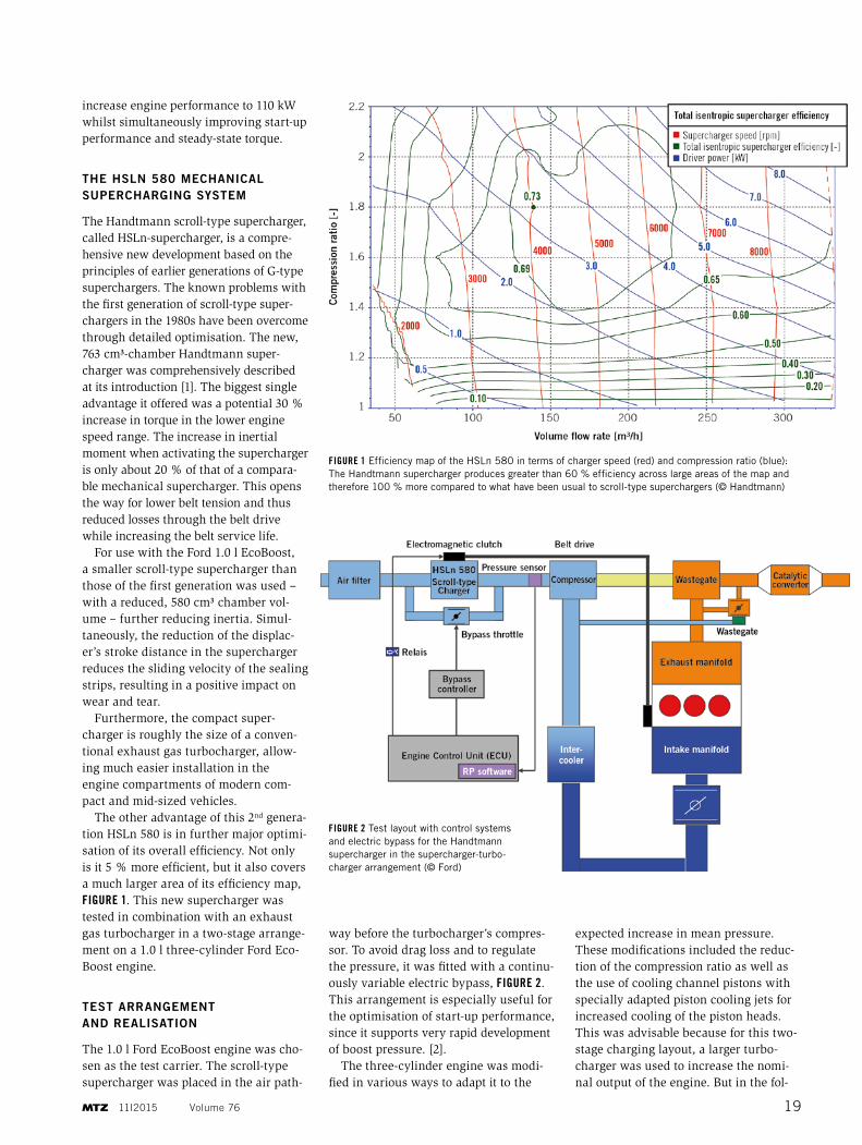
The other advantage of this 2nd genera-tion HSLn 580 is in further major optimi-sation of its overall efficiency. Not only is it 5 % more efficient, but it also covers a much larger area of its efficiency map, FIGURE 1. This new supercharger was tested in combination with an exhaust gas turbocharger in a two-stage arrange-ment on a 1.0 l three-cylinder Ford Eco-Boost engine.
TEST ARRANGEMENT AND REALISATION
The 1.0 l Ford EcoBoost engine was cho-sen as the test carrier. The scroll-type supercharger was placed in the air path-
way before the turbocharger’s compres-sor. To avoid drag loss and to regulate the pressure, it was fitted with a continu-ously variable electric bypass, FIGURE 2. This arrangement is especially useful for the optimisation of start-up performance, since it supports very rapid development of boost pressure. [2].
The three-cylinder engine was modi-fied in various ways to adapt it to the
expected increase in mean pressure. These modifications included the reduc-tion of the compression ratio as well as the use of cooling channel pistons with specially adapted piston cooling jets for increased cooling of the piston heads. This was advisable because for this two-stage charging layout, a larger turbo-charger was used to increase the nomi-nal output of the engine. But in the fol-
FIGURE 1 Efficiency map of the HSLn 580 in terms of charger speed (red) and compression ratio (blue): The Handtmann supercharger produces greater than 60 % efficiency across large areas of the map and therefore 100 % more compared to what have been usual to scroll-type superchargers (© Handtmann)
FIGURE 2 Test layout with control systems and electric bypass for the Handtmann supercharger in the supercharger-turbo-charger arrangement (© Ford)
11I2015 Volume 76 19
lowing, attention was focused on an improved torque behaviour in the low engine speed range.
The HSLn 580’s single-level belt drive is driven by an additional pulley located at the free end of the crankshaft. The demand-based activation of the mechanical supercharger is realised through an integrated electromechani-cal coupling in the hub of the charger’s shaft. The belt is running at all times in this arrangement and creates com-mensurate drag loss. One conceivable alternative that could offer improvement would be to move the coupling to a pulley directly on the crankshaft.
System control was implemented through the integration of additional add-on rapid prototype software pack-ages into the existing software struc-ture. An additional pressure sensor between the scroll-type supercharger’s outlet and the intake of the turbo-charger delivers the control signal for the demand-based pressure regulation during two-stage operation.
All rig testing was carried out at the Ford development centre in Cologne- Merkenich. Alongside stationary meas-urements, special attention was paid to determining the dynamic behaviour of the system during step changes in load.
TEST RESULTS – STATIONARY FULL-LOAD
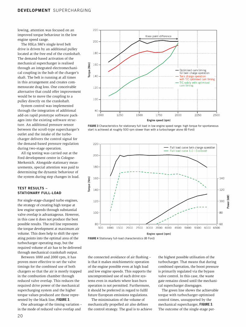
For single-stage-charged turbo engines, the strategy of creating high torque at low engine speeds through substantial valve overlap is advantageous. However, in this case it does not produce the best possible results. The red line represents the torque development at maximum air volume. This does help to shift the oper-ating points into the optimal area of the turbocharger operating map, but the required volume of air has to be delivered through mechanical crankshaft output.
Between 1000 and 2000 rpm, it has proven more effective to set the valve timings for the combined use of both chargers so that the air is mostly trapped in the combustion chamber through reduced valve overlap. This reduces the required drive power of the mechanical supercharging system and the higher torque values produced are those repre-sented by the black line, FIGURE 3.
One advantage of the timing variation – in the mode of reduced valve overlap and
the connected avoidance of air flushing – is that it makes stoichiometric operation of the engine possible even at high load and low engine speeds. This supports the uncompromised use of such drive sys-tems even in markets where lean burn operation is not permitted. Furthermore, it should be preferred in regard to fulfil future European emissions regulations.
The minimisation of the volume of mechanically propelled air also defines the control strategy. The goal is to achieve
the highest possible utilisation of the turbocharger. That means that during combined operation, the boost pressure is primarily regulated via the bypass valve control. In this case, the waste gate remains closed until the mechani-cal supercharger disengages.
The green line shows the achievable torque with turbocharger-optimised control times, unsupported by the mechanical supercharger, FIGURE 3. The outcome of the single-stage per-
FIGURE 3 Characteristics for stationary full load in low engine speed range: high torque for spontaneous start is achieved at roughly 500 rpm slower than with a turbocharger alone (© Ford)
FIGURE 4 Stationary full-load characteristics (© Ford)
DEVELOPMENT SUPERCHARGING
20
formance increase also raises the “knee point,” that is the first point at which maximum torque is available, by roughly 500 rpm. The complete torque curve compared to a series-standard 1.0 l Eco-Boost is shown in FIGURE 4.
The possibility of supporting the tur-bocharger in coupled operation with the scroll-type supercharger is clearly advan-tageous in the 1000 to 2000 rpm engine speed range. Above 2000 rpm in station-ary operation, there is no measurable advantage to the combined use of both chargers. However, for improved engine dynamics, limited use of the mechanical supercharger at higher engine speeds is nonetheless very useful.
DYNAMIC RESPONSE
A good measure for evaluating system dynamics is the evaluation of the time it takes at constant engine speed for an engine to go from a defined low load point (bmep=100 kPa) to 90 % of its maximum possible stationary torque. The result of such a test at 1300 rpm, comparing a series-standard engine and the two-stage supercharged version, is shown in FIGURE 5. It must however be taken into account that the series engine delivers less stationary torque during turbo operation. The two-stage super-charged version needs around 3.0 s less to achieve 90 % of maximum torque (1.0 instead of 4.0 s). During combined operation, the 20 Nm higher torque level is available 0.5 s later, just 1.5 s after the load step. The corresponding mean pres-sure curves to this are in the upper, left-hand diagram, where the red line with its earlier and higher power development clearly stands out.
At 1500 rpm in overboost mode, the series-standard engine also reaches its maximum torque of 200 Nm under full load. The dynamic advantage of the two-stage supercharging alone is a remarkable 1.5 s here as well. This again improves drivability significantly thanks to the two-stage supercharging.
The spontaneous boost pressure build-up directly behind the HSLn 580 supercharger with its typical, almost vertically increasing pressure curve is shown in the lower right-hand diagram in FIGURE 5. The diagram above it describes the pressure build-up in the intake manifold behind both chargers for the different versions.
11I2015 Volume 76 21
Visit ourstand at
MTZ Heavy-Duty-,
On- and Off-
Highway Engines
Nov 24–25, 2015Speyer,Germany
Leading in development and manufacturing of oil mist separators for combustion engines and turbines.
Emission reduction &increased efficiencyby the use of highly efficient oil mist separators at crankcase and lube oil tank ventilation.
The world´s only
oil mist s
eparator with
GL type approval
www.ut99.ch
Benefits of UT99 oil mist separators
• Emission reduction, even to obtain EPA Tier 4 final
• Reliable increase of efficiency at gas / dual-fuel engines
• No deposits on turbocharger
• No leakage of oil and oil mist
• Long-lasting operational reliability
Key features of UT99 oil mist separators
• For engines from 50 kW to 100 MW
and turbines up to 2000 MW
• For closed (CCV) / open (OCV) crankcase and lube oil tank (OTV) ventilation
• Residual oil amount < 1 mg / m³ guaranteed
• Filter service lifetime up to 24.000 h
• ATEX (ex-proof) approved design available
Long-term supplier for many well-known engine, turbine and power plants manufacturer.
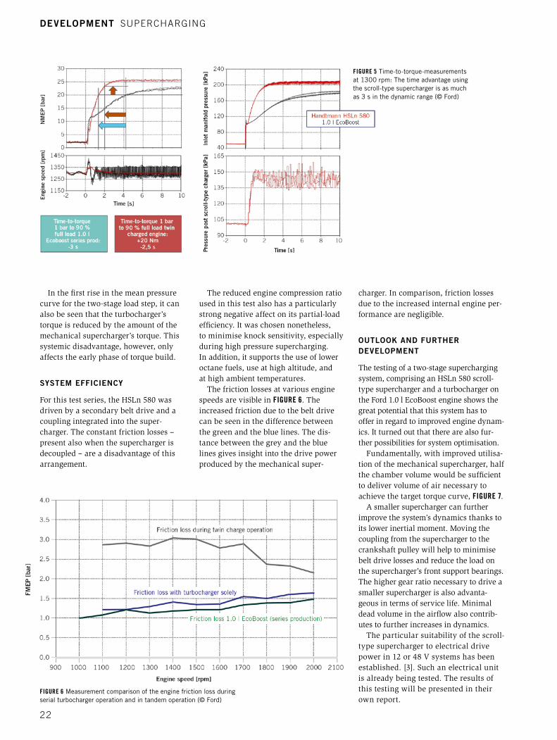
In the first rise in the mean pressure curve for the two-stage load step, it can also be seen that the turbocharger’s torque is reduced by the amount of the mechanical supercharger’s torque. This systemic disadvantage, however, only affects the early phase of torque build.
SYSTEM EFFICIENCY
For this test series, the HSLn 580 was driven by a secondary belt drive and a coupling integrated into the super-charger. The constant friction losses – present also when the supercharger is decoupled – are a disadvantage of this arrangement.
The reduced engine compression ratio used in this test also has a particularly strong negative affect on its partial-load efficiency. It was chosen nonetheless, to minimise knock sensitivity, especially during high pressure supercharging. In addition, it supports the use of lower octane fuels, use at high altitude, and at high ambient temperatures.
The friction losses at various engine speeds are visible in FIGURE 6. The increased friction due to the belt drive can be seen in the difference between the green and the blue lines. The dis-tance between the grey and the blue lines gives insight into the drive power produced by the mechanical super-
charger. In comparison, friction losses due to the increased internal engine per-formance are negligible.
OUTLOOK AND FURTHER DEVELOPMENT
The testing of a two-stage supercharging system, comprising an HSLn 580 scroll-type supercharger and a turbocharger on the Ford 1.0 l EcoBoost engine shows the great potential that this system has to offer in regard to improved engine dynam-ics. It turned out that there are also fur-ther possibilities for system optimisation.
Fundamentally, with improved utilisa-tion of the mechanical supercharger, half the chamber volume would be sufficient to deliver volume of air necessary to achieve the target torque curve, FIGURE 7.
A smaller supercharger can further improve the system’s dynamics thanks to its lower inertial moment. Moving the coupling from the supercharger to the crankshaft pulley will help to minimise belt drive losses and reduce the load on the supercharger’s front support bearings. The higher gear ratio necessary to drive a smaller supercharger is also advanta-geous in terms of service life. Minimal dead volume in the airflow also contrib-utes to further increases in dynamics.
The particular suitability of the scroll-type supercharger to electrical drive power in 12 or 48 V systems has been established. [3]. Such an electrical unit is already being tested. The results of this testing will be presented in their own report.
FIGURE 5 Time-to-torque-measurements at 1300 rpm: The time advantage using the scroll-type supercharger is as much as 3 s in the dynamic range (© Ford)
FIGURE 6 Measurement comparison of the engine friction loss during serial turbocharger operation and in tandem operation (© Ford)
DEVELOPMENT SUPERCHARGING
22
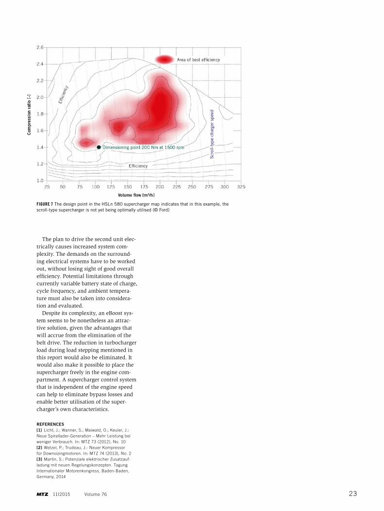
FIGURE 7 The design point in the HSLn 580 supercharger map indicates that in this example, the scroll-type supercharger is not yet being optimally utilised (© Ford)
The plan to drive the second unit elec-trically causes increased system com-plexity. The demands on the surround-ing electrical systems have to be worked out, without losing sight of good overall efficiency. Potential limitations through currently variable battery state of charge, cycle frequency, and ambient tempera-ture must also be taken into considera-tion and evaluated.
Despite its complexity, an eBoost sys-tem seems to be nonetheless an attrac-tive solution, given the advantages that will accrue from the elimination of the belt drive. The reduction in turbocharger load during load stepping mentioned in this report would also be eliminated. It would also make it possible to place the supercharger freely in the engine com-partment. A supercharger control system that is independent of the engine speed can help to eliminate bypass losses and enable better utilisation of the super-charger’s own characteristics.
REFERENCES[1] Licht, J.; Wanner, S.; Maiwald, O.; Keuler, J.: Neue Spirallader-Generation – Mehr Leistung bei weniger Verbrauch. In: MTZ 73 (2012), No. 10[2] Wetzel, P.; Trudeau, J.: Neuer Kompressor für Downsizingmotoren. In: MTZ 74 (2013), No. 2[3] Martin, S.: Potenziale elektrischer Zusatzauf-ladung mit neuen Regelungskonzepten. Tagung Internationaler Motorenkongress, Baden-Baden, Germany, 2014
11I2015 Volume 76 23