two-dimensional moving phantom sensation created by
TRANSCRIPT
Two-Dimensional Moving Phantom Sensation Created byRotational Skin Stretch Distribution
Arata Horie, Zendai Kashino, Hideki Shimobayashi, Masahiko Inami
Abstract— This study reports on one of the first attemptsto achieve a sense of tactile motion in two-dimensions usingan array of stationary rotational skin stretch elements pre-senting a moving phantom sensation. Herein, we propose analgorithm with two independent control parameters (the sizeof the stimulus area and the size of the area with maximumstimulus) for generating the moving phantom sensation usingour skin stretch tactile display device. In our investigations,we first conducted an experiment to identify the relationshipbetween the mechanical action of our device (a rotation) andthe perceived stimulus intensity. Then, using the proposedalgorithm, we evaluated the continuity, consistency, and positionclarity of phantom sensations under several control parametersand motion direction conditions. Our results showed that bothcontrol parameters had a significant effect on the continuityof the stimulus in all directions. Furthermore, we confirmedthat, using our current algorithm, the size of the stimulus areahas a trade-off relation with the stimulus position clarity. Weconclude the paper by discussing our findings, new control pa-rameters that may directly determine continuity of the phantomsensation, and factors that may contribute to the consistencyof stimulus intensity. This paper provides fundamental insightsinto the presentation of skin stretch based moving phantomsensations.
I. INTRODUCTION
The sense of touch has a spatial component which allowsus to perceive tactile motion on our skin. For example, wecan perceive when an object rolls on the palm of our handor when we are stroked on the arm or back. Reproducing orcreating such experiences is an important issue for VR ap-plications, remote manipulation, and tactile communication.
The most direct method for generating tactile motion is toactually move the end-effector over the skin (e.g., directlystroking the skin with an end-effector [1]). On the otherhand, such approaches have limited the spatial scalabilityand expressiveness. This makes them impractical to apply inmany cases, especially to large areas such as the back.
A number of researchers have realized tactile motionpresentations with spatial stimulus distributions. They realizethe sensation of a moving stimulus through two tactileillusions: phantom tactile sensation [2] and apparent tactilemotion [3]. Choi et al. define a moving phantom sensationto be the creation of a tactile motion using these two tactileillusions [4]. An example of work realizing this phantomsensation is TactileBrush [5], which creates a moving phan-tom sensation using vibrotactile stimulus according to an
This work was supported by JST ERATO Grant Number JPM-JER1701,Japan(INAMI JIZAI Body Project).
The authors are with the Information Somatics Lab, RCAST, The Univer-sity of Tokyo. [email protected]
algorithm to generate the sensation of a continuously movingstimuli in two dimensions.
There are many methods for presenting tactile motionusing vibrotactile stimuli [5], [4], [6], [7]. However, vibro-tactile stimulus is not suitable for long-term exposure. Forexample, prolonged exposure to vibrational stimulus leads todesensitization [8]. As people spend more time in simulatedenvironments with simulated stimuli, there will be a need tohave a method of tactile stimulus that may not suffer from adegraded experience with prolonged exposure. One candidatetactile stimulus which may be able to provide a long-term stimulus without a degraded experience is skin stretch.However, there are comparatively few works investigatingphenomena such as the phantom moving sensation in thecontext of skin stretch stimuli [9].
Researchers have proposed a variety of devices thatpresent skin shear deformation on various body parts [10],[11], [12], [13], [14]. Other work has aimed to presenta distribution of shear deformation on larger areas of thebody, such as the back [15]. Such large-area devices couldbenefit significantly from being able to present movingphantom sensations as it significantly increases its freedomof expression.
There is a high likelihood that a moving phantom sensationcan be generated by controlling the skin stretch stimulusintensity distribution over an area of skin. Past work hasshown that modulating vibration stimulus intensity is a goodapproach for presenting a continuous moving phantom sen-sation [7]. This suggests that modulating stimulus intensitycould be used as an approach for presenting a movingphantom sensation in other kinds of tactile stimuli. Recentworks producing continuous tactile motion using normalforce [16] and displacement [17] show that tactile sensationsother than vibration have the potential to generate movingphantom sensations. Since skin shear deformations have awider dynamic range of perceptual intensity than normaldisplacements [18], a moving phantom sensation of skinstretch might be induced taking a similar approach.
Past work has reported on generating a moving phan-tom sensation using rotational skin shear stimulus elementswhich slip on the skin [19]. However, to our knowledge, thereis no report showing that the moving phantom sensation canbe induced using rotational skin stretch without slip. As such,it is not clear how the rotation angles of multiple actuatorsshould be controlled in order to induce a moving phantomsensation. Furthermore, it is not clear how qualities of thestimulus, such as continuity and position clarity, might beaffected by the actuator control parameters.
© 2021 IEEE. Personal use of this material is permitted. Permission from IEEE must be obtained for all other uses, in any current or future media, including reprinting/republishing this material for advertising or promotional purposes, creating new collective works, for resale or redistribution to servers or lists, or reuse of any copyrighted component of this work in other works.
(a) (b)
60°
(c)
12345678
1 2 3 4 5 6
20 mm
50 mm
Stimulators used in Exp.1
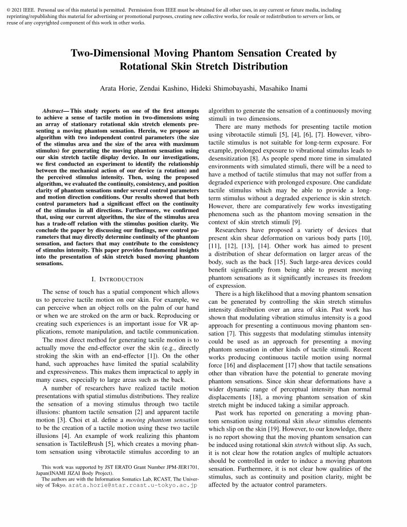
Fig. 1. (a) Apparatus overview. (b) Close up picture of one module. (c)The slant of the back was 60° from horizontal.
Herein, we report on an investigation into the presentationof a two-degree-of-freedom(DoF) moving phantom sensationusing rotational skin strech distribution stimuli. First, weprovide basic information about the apparatus used in theexperiments. Then, we describe the method and result ofexperiments conducted to relate actuator rotation angle toperceived skin stretch intensity. Finally, we propose an algo-rithm for presenting a moving phantom sensation with two-DoF with two independent control parameters and evaluatedit through experimentation. Through this evaluation, wedetermined how the two control parameters influence theperceived sensation in terms of continuity, consistency, andposition clarity of the stimuli.
II. EXPERIMENTAL APPARATUS
We employed a two-dimensional large-area haptic displaysystem to investigate moving phantom sensations of skinstretch. The hardware of this system consists of an arrayof skin stretch presentation elements, embedded in modulesattached to a chair, controlled by a computer through acontrol board. Fig. 1(a) shows the haptic display and onemodule containing four stimulus elements. Each elementrotates to deform the skin on the user’s back and generate alarge-area spatio-temporal strain pattern.
Each skin stretch presentation module consists of a set oftactors, attached to servo motors, and a holding apparatusas shown in Fig. 1(b). Each tactor is a chloroprene rubbersponge with a diameter of 20 mm and a thickness of 5 mm.We chose this material because it lacks sharp edges andhas a high coefficient of friction. These properties preventpain by avoiding focal pressures and slipping of the tactorsrespectively. As noted above, each tactor is mounted directlyon the head of a servo motor to allow it to rotate in place.
The servo motors (RS204MD, Futaba) have a maximumrotational torque of 2.1 Nm and are held together in theholding apparatus. The maximum rotational angle of theservo motor is 300°, which is enough for provide skindeformation. The holding apparatus was 3D printed to keepa distance of 50 mm between tactors, which is around thetwo-point discrimination threshold of the human back [20].This system we used in this study had 12 modules with 4servomotors each, for a total of 48 stimulus elements. The
PC
Monitor
Keyboard
Headphone
Control Board
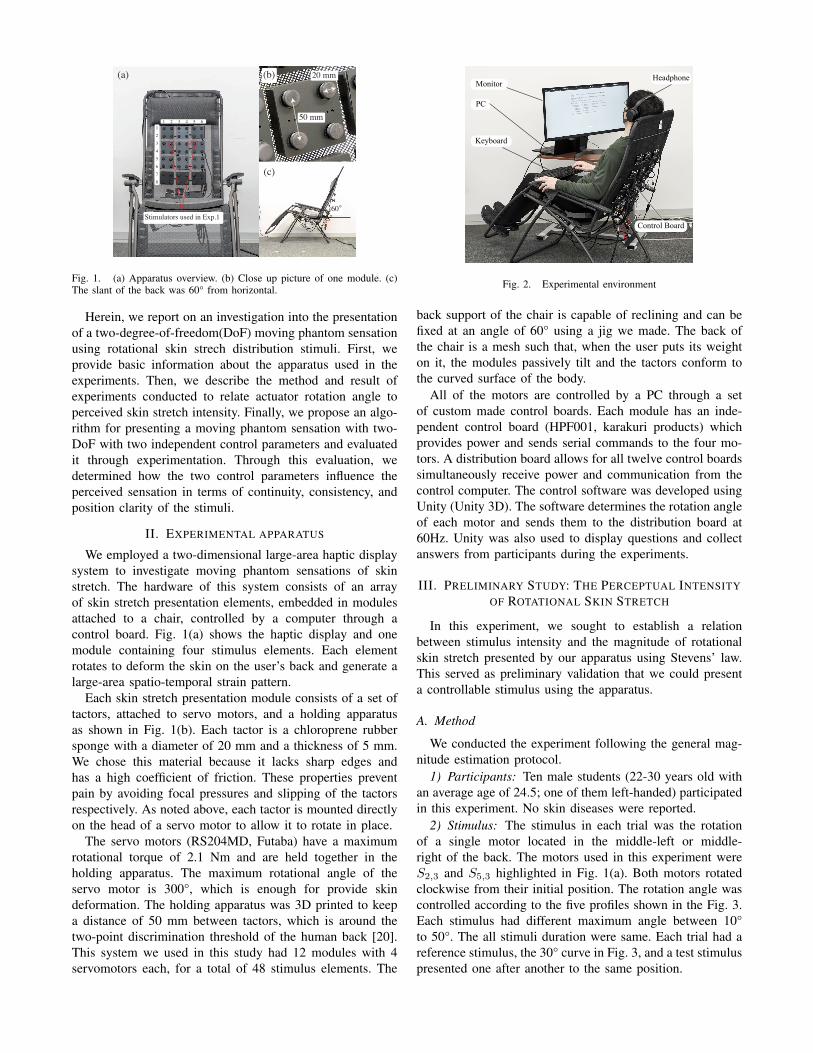
Fig. 2. Experimental environment
back support of the chair is capable of reclining and can befixed at an angle of 60° using a jig we made. The back ofthe chair is a mesh such that, when the user puts its weighton it, the modules passively tilt and the tactors conform tothe curved surface of the body.
All of the motors are controlled by a PC through a setof custom made control boards. Each module has an inde-pendent control board (HPF001, karakuri products) whichprovides power and sends serial commands to the four mo-tors. A distribution board allows for all twelve control boardssimultaneously receive power and communication from thecontrol computer. The control software was developed usingUnity (Unity 3D). The software determines the rotation angleof each motor and sends them to the distribution board at60Hz. Unity was also used to display questions and collectanswers from participants during the experiments.
III. PRELIMINARY STUDY: THE PERCEPTUAL INTENSITYOF ROTATIONAL SKIN STRETCH
In this experiment, we sought to establish a relationbetween stimulus intensity and the magnitude of rotationalskin stretch presented by our apparatus using Stevens’ law.This served as preliminary validation that we could presenta controllable stimulus using the apparatus.
A. Method
We conducted the experiment following the general mag-nitude estimation protocol.
1) Participants: Ten male students (22-30 years old withan average age of 24.5; one of them left-handed) participatedin this experiment. No skin diseases were reported.
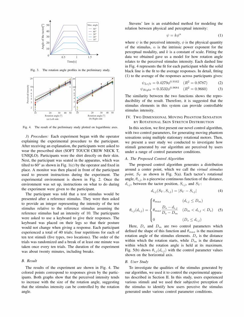
2) Stimulus: The stimulus in each trial was the rotationof a single motor located in the middle-left or middle-right of the back. The motors used in this experiment wereS2,3 and S5,3 highlighted in Fig. 1(a). Both motors rotatedclockwise from their initial position. The rotation angle wascontrolled according to the five profiles shown in the Fig. 3.Each stimulus had different maximum angle between 10°to 50°. The all stimuli duration were same. Each trial had areference stimulus, the 30° curve in Fig. 3, and a test stimuluspresented one after another to the same position.
Time[s]
Ang
le o
f the
tact
or[ °] 50
40
30
20
10
0 0.5 1 1.5
50°40°30°20°10°
Max. angle
Fig. 3. The rotation angle profiles in the preliminary study.
10 20 504030
1086543
2
20
1086543
2
20
10 20 504030
(a) Left side (b) Right sideRotation angle [°] Rotation angle [°]
Perc
eive
d in
tens
ity
Fig. 4. The result of the preliminary study plotted on logarithmic axes.
3) Procedure: Each experiment began with the operatorexplaining the experimental procedure to the participant.After receiving an explanation, the participants were asked towear the prescribed shirt (SOFT TOUCH CREW NECK T,UNIQLO). Participants wore the shirt directly on their skin.Next, the participant was seated in the apparatus, which wastilted to 60° as shown in Fig. 1(c) by the operator and fixed inplace. A monitor was then placed in front of the participantused to present instructions during the experiment. Theexperimental environment is shown in Fig. 2. Once theenvironment was set up, instructions on what to do duringthe experiment were given to the participant.
The participant was told that a test stimulus would bepresented after a reference stimulus. They were then askedto provide an integer representing the intensity of the teststimulus relative to the reference stimulus assuming thereference stimulus had an intensity of 10. The participantswere asked to use a keyboard to give their responses. Thekeyboard was placed on their legs so that their posturewould not change when giving a response. Each participantexperienced a total of 40 trials; four repetitions for each often test stimuli (five types, two locations). The order of thetrials was randomized and a break of at least one minute wastaken once every ten trials. The duration of the experimentwas about twenty minutes, including breaks.
B. Result
The results of the experiment are shown in Fig. 4. Thecolored points correspond to responses given by the partic-ipants. Both graphs show that the perceived intensity tendsto increase with the size of the rotation angle, suggestingthat the stimulus intensity can be controlled by the rotationangle.
Stevens’ law is an established method for modeling therelation between physical and perceptual intensity:
ψ = kφα (1)
where ψ is the perceived intensity, φ is the physical quantityof the stimulus, α is the intrinsic power exponent for theperceptual modality, and k is a constant of scale. Fitting thedata we obtained gave us a model for how rotation anglerelates to the perceived stimulus intensity. Each dashed linein Fig. 4 represents the fit for each participant while the solidblack line is the fit to the average responses. In detail, fitting(1) to the average of the responses across participants gives:
ψLeft = 0.4279φ0.9162 (R2 = 0.9787) (2)
ψRight = 0.3532φ0.9684 (R2 = 0.9660) (3)
The similarity between the two functions shows the repro-ducibility of the result. Therefore, it is suggested that thestimulus elements in this system can provide controllablestimulus intensity.
IV. TWO DIMENSIONAL MOVING PHANTOM SENSATIONBY ROTATIONAL SKIN STRETCH DISTRIBUTION
In this section, we first present our novel control algorithm,with two control parameters, for generating moving phantomsensations using multiple stationary rotational motors. Then,we present a user study we conducted to investigate howstimuli generated by our algorithm are perceived by usersunder a range of control parameter conditions.
A. The Proposed Control AlgorithmThe proposed control algorithm generates a distribution
around a center point, which we call the virtual stimuluspoint, SV as shown in Fig. 5(a). Each tactor’s rotationalangle, θi,j , is a piecewise continuous function of the distance,di,j , between the tactor position, Si,j , and SV :
di,j(SV , Si,j) = |SV − Si,j | (4)
θi,j(di,j) =
θmax (di,j ≤ Dm)
θmaxDs − di,jDs −Dm
(Dm < di,j < Ds)
0 (Ds ≤ di,j)
(5)
Here, Ds and Dm are two control parameters whichdefined the shape of this function and θmax is the maximumrotation angle of the stimulus elements. Ds is the distancewithin which the rotation starts, while Dm is the distancewithin which the rotation angle is held at its maximum.Fig. 5(b) shows θi,j(di,j) with the control parameter valuesshown on the horizontal axis.
B. User StudyTo investigate the qualities of the stimulus generated by
our algorithm, we used it to control the experimental appara-tus described in Section II. In this study, users experiencedvarious stimuli and we used their subjective perception ofthe stimulus to identify how users perceive the stimulusgenerated under various control parameter conditions.
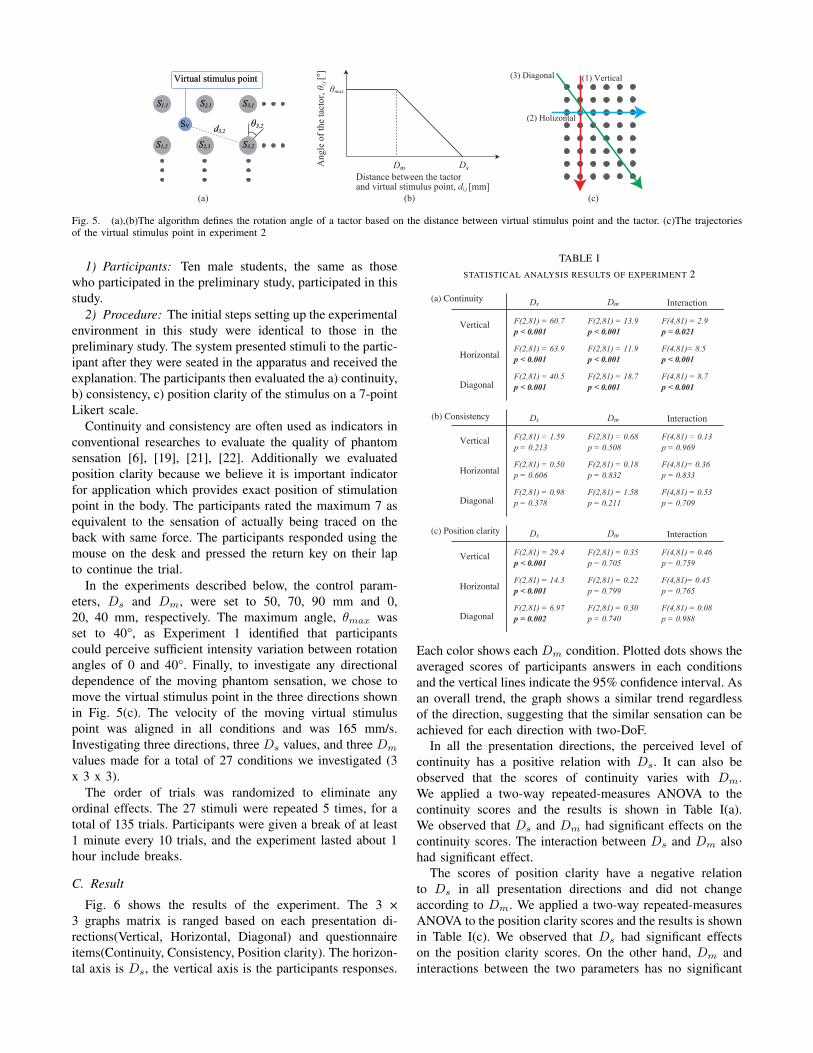
(1) Vertical
(2) Holizontal
(3) DiagonalVirtual stimulus pointVirtual stimulus point
S1,1S1,1
S1,2S1,2
S2,1S2,1 S3,1S3,1
S3,2S3,2S2,3S2,3
Distance between the tactor and virtual stimulus point, di,j [mm]
Ang
le o
f the
tact
or, θ
i,j [ °
]
Dm Ds
θmax
d3,2d3,2SVSV θ3,2θ3,2
(a) (b) (c)
Fig. 5. (a),(b)The algorithm defines the rotation angle of a tactor based on the distance between virtual stimulus point and the tactor. (c)The trajectoriesof the virtual stimulus point in experiment 2
1) Participants: Ten male students, the same as thosewho participated in the preliminary study, participated in thisstudy.
2) Procedure: The initial steps setting up the experimentalenvironment in this study were identical to those in thepreliminary study. The system presented stimuli to the partic-ipant after they were seated in the apparatus and received theexplanation. The participants then evaluated the a) continuity,b) consistency, c) position clarity of the stimulus on a 7-pointLikert scale.
Continuity and consistency are often used as indicators inconventional researches to evaluate the quality of phantomsensation [6], [19], [21], [22]. Additionally we evaluatedposition clarity because we believe it is important indicatorfor application which provides exact position of stimulationpoint in the body. The participants rated the maximum 7 asequivalent to the sensation of actually being traced on theback with same force. The participants responded using themouse on the desk and pressed the return key on their lapto continue the trial.
In the experiments described below, the control param-eters, Ds and Dm, were set to 50, 70, 90 mm and 0,20, 40 mm, respectively. The maximum angle, θmax wasset to 40°, as Experiment 1 identified that participantscould perceive sufficient intensity variation between rotationangles of 0 and 40°. Finally, to investigate any directionaldependence of the moving phantom sensation, we chose tomove the virtual stimulus point in the three directions shownin Fig. 5(c). The velocity of the moving virtual stimuluspoint was aligned in all conditions and was 165 mm/s.Investigating three directions, three Ds values, and three Dm
values made for a total of 27 conditions we investigated (3x 3 x 3).
The order of trials was randomized to eliminate anyordinal effects. The 27 stimuli were repeated 5 times, for atotal of 135 trials. Participants were given a break of at least1 minute every 10 trials, and the experiment lasted about 1hour include breaks.
C. Result
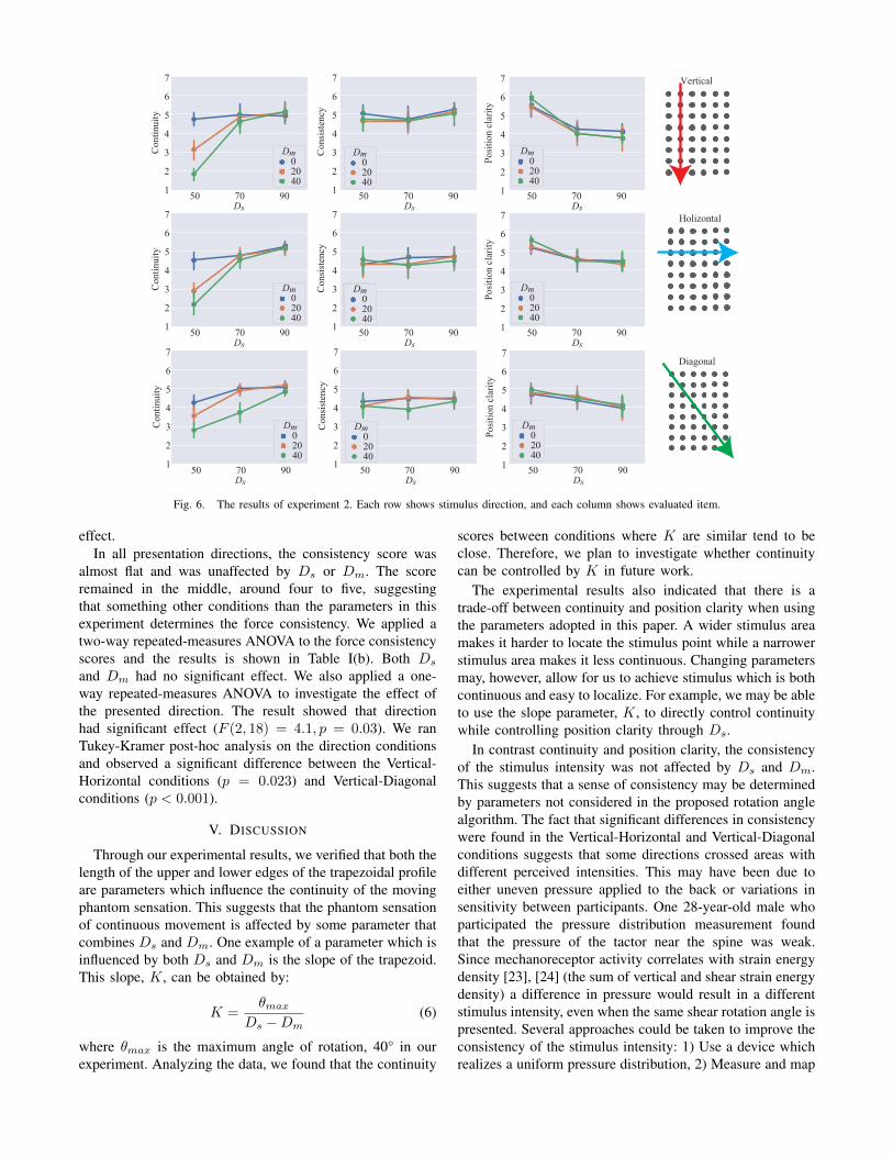
Fig. 6 shows the results of the experiment. The 3 ×3 graphs matrix is ranged based on each presentation di-rections(Vertical, Horizontal, Diagonal) and questionnaireitems(Continuity, Consistency, Position clarity). The horizon-tal axis is Ds, the vertical axis is the participants responses.
TABLE ISTATISTICAL ANALYSIS RESULTS OF EXPERIMENT 2
F(2,81) = 60.7p < 0.001
Ds(a) Continuity
Vertical
Horizontal
Diagonal
F(2,81) = 13.9p < 0.001
Dm Interaction
F(4,81) = 2.9p = 0.021
F(2,81) = 63.9p < 0.001
F(2,81) = 11.9p < 0.001
F(4,81)= 8.5p < 0.001
F(2,81) = 40.5p < 0.001
F(2,81) = 18.7p < 0.001
F(4,81) = 8.7 p < 0.001
(b) Consistency
(c) Position clarity
F(2,81) = 1.59p = 0.213
Ds
Vertical
Horizontal
Diagonal
F(2,81) = 0.68p = 0.508
Dm Interaction
F(4,81) = 0.13p = 0.969
F(2,81) = 0.50p = 0.606
F(2,81) = 0.18p = 0.832
F(4,81)= 0.36p = 0.833
F(2,81) = 0.98p = 0.378
F(2,81) = 1.58p = 0.211
F(4,81) = 0.53 p = 0.709
F(2,81) = 29.4p < 0.001
Ds
Vertical
Horizontal
Diagonal
F(2,81) = 0.35p = 0.705
Dm Interaction
F(4,81) = 0.46p = 0.759
F(2,81) = 14.3p < 0.001
F(2,81) = 0.22p = 0.799
F(4,81)= 0.45p = 0.765
F(2,81) = 6.97p = 0.002
F(2,81) = 0.30p = 0.740
F(4,81) = 0.08p = 0.988
Each color shows each Dm condition. Plotted dots shows theaveraged scores of participants answers in each conditionsand the vertical lines indicate the 95% confidence interval. Asan overall trend, the graph shows a similar trend regardlessof the direction, suggesting that the similar sensation can beachieved for each direction with two-DoF.
In all the presentation directions, the perceived level ofcontinuity has a positive relation with Ds. It can also beobserved that the scores of continuity varies with Dm.We applied a two-way repeated-measures ANOVA to thecontinuity scores and the results is shown in Table I(a).We observed that Ds and Dm had significant effects on thecontinuity scores. The interaction between Ds and Dm alsohad significant effect.
The scores of position clarity have a negative relationto Ds in all presentation directions and did not changeaccording to Dm. We applied a two-way repeated-measuresANOVA to the position clarity scores and the results is shownin Table I(c). We observed that Ds had significant effectson the position clarity scores. On the other hand, Dm andinteractions between the two parameters has no significant
Con
tinui
ty
Con
sist
ency
Posi
tion
clar
ity
7
6
5
4
3
2
1 50 70 90Ds
Dm02040
7
6
5
4
3
2
1
7
6
5
4
3
2
150 70 90 50 70 90Ds Ds
Dm02040
Dm02040
Con
tinui
ty
Con
sist
ency
Posi
tion
clar
ity
7
6
5
4
3
2
1 50 70 90Ds
Dm02040
7
6
5
4
3
2
1
7
6
5
4
3
2
150 70 90 50 70 90Ds Ds
Dm02040
Dm02040
Con
tinui
ty
Con
sist
ency
Posi
tion
clar
ity
7
6
5
4
3
2
1 50 70 90Ds
Dm02040
7
6
5
4
3
2
1
7
6
5
4
3
2
150 70 90 50 70 90Ds Ds
Dm02040
Dm02040
Vertical
Holizontal
Diagonal
Fig. 6. The results of experiment 2. Each row shows stimulus direction, and each column shows evaluated item.
effect.In all presentation directions, the consistency score was
almost flat and was unaffected by Ds or Dm. The scoreremained in the middle, around four to five, suggestingthat something other conditions than the parameters in thisexperiment determines the force consistency. We applied atwo-way repeated-measures ANOVA to the force consistencyscores and the results is shown in Table I(b). Both Ds
and Dm had no significant effect. We also applied a one-way repeated-measures ANOVA to investigate the effect ofthe presented direction. The result showed that directionhad significant effect (F (2, 18) = 4.1, p = 0.03). We ranTukey-Kramer post-hoc analysis on the direction conditionsand observed a significant difference between the Vertical-Horizontal conditions (p = 0.023) and Vertical-Diagonalconditions (p < 0.001).
V. DISCUSSION
Through our experimental results, we verified that both thelength of the upper and lower edges of the trapezoidal profileare parameters which influence the continuity of the movingphantom sensation. This suggests that the phantom sensationof continuous movement is affected by some parameter thatcombines Ds and Dm. One example of a parameter which isinfluenced by both Ds and Dm is the slope of the trapezoid.This slope, K, can be obtained by:
K =θmax
Ds −Dm(6)
where θmax is the maximum angle of rotation, 40° in ourexperiment. Analyzing the data, we found that the continuity
scores between conditions where K are similar tend to beclose. Therefore, we plan to investigate whether continuitycan be controlled by K in future work.
The experimental results also indicated that there is atrade-off between continuity and position clarity when usingthe parameters adopted in this paper. A wider stimulus areamakes it harder to locate the stimulus point while a narrowerstimulus area makes it less continuous. Changing parametersmay, however, allow for us to achieve stimulus which is bothcontinuous and easy to localize. For example, we may be ableto use the slope parameter, K, to directly control continuitywhile controlling position clarity through Ds.
In contrast continuity and position clarity, the consistencyof the stimulus intensity was not affected by Ds and Dm.This suggests that a sense of consistency may be determinedby parameters not considered in the proposed rotation anglealgorithm. The fact that significant differences in consistencywere found in the Vertical-Horizontal and Vertical-Diagonalconditions suggests that some directions crossed areas withdifferent perceived intensities. This may have been due toeither uneven pressure applied to the back or variations insensitivity between participants. One 28-year-old male whoparticipated the pressure distribution measurement foundthat the pressure of the tactor near the spine was weak.Since mechanoreceptor activity correlates with strain energydensity [23], [24] (the sum of vertical and shear strain energydensity) a difference in pressure would result in a differentstimulus intensity, even when the same shear rotation angle ispresented. Several approaches could be taken to improve theconsistency of the stimulus intensity: 1) Use a device whichrealizes a uniform pressure distribution, 2) Measure and map
the perceived intensities presented when the tactors rotate.The first approach would require equalizing the pressureapplied to the skin from the tactors. For example, we couldselect passive mechanisms, such as a rocher bogie [25],or active pressure optimization mechanisms with pressuresensors and additional actuators. The second approach is toderive the model of the relationship between rotation angleand perceived intensity for multiple points on the back andcontrol perceived intensity rather than physical rotation. Thesecond approach has been taken by Yun et al. in their studyinducing a moving phantom sensation using discrete vibra-tion actuator [6]. This approach may be effective in our caseas well, since the approach can eliminate perceived intensitydifferences caused by any sources, including pressure.
VI. CONCLUSION
In this study, we proposed an algorithm for presentinga two-DoF moving phantom sensation using a stationaryarray of skin stretch stimulus elements and reported onhow the algorithm’s control parameters affect the qualityof experience. We conducted experiments investigating theeffect of the control parameters using a chair-type devicewith 48 independently rotating tactors working to presenta skin stretch distribution on the user’s back. To identifythe appropriate control parameters, we first conducted themagnitude estimation procedure to identify the relationshipbetween the perceived stimulus intensity and the tactorrotation angle. The results showed that the stimulus intensitycan be controlled for angles up to 50° of rotation. Then, weconducted an extensive study exploring how two control pa-rameters determining the size of the stimulus region and thesize of the region keeping maximum rotation angle affectedthe sensation generated by the algorithm. In this study, wefocused on evaluating how the control parameters influencedthe continuity, consistency, and position clarity of the movingphantom sensation generated by the stimulus. The resultsshowed that the parameters we proposed had a significanteffects on continuity and position clarity. Furthermore, weidentified that, given our current parameters, continuity andposition clarity have a trade-off relation. Given these results,we discussed several new control parameters which could betuned to create a sensation which has both high continuityand position clarity. We additionally considered what param-eters might affect the consistency of stimulus intensity andprovide ideas on how to deliver a more consistent stimulus.These findings and our discussions can serve as a referencewhen designing skin stretch distribution stimuli with theobjective of inducing a moving phantom sensation.
REFERENCES
[1] E. Eichhorn, R. Wettach, and E. Hornecker, “A stroking device forspatially separated couples,” in Proc. 10th Int. Conf. Human Comput.Interact. Mobile Devices Services, Sept. 2008, pp. 303–306.
[2] D. S. Alles, “Information transmission by phantom sensations,” IEEETrans. Man-machine Syst., vol. 11, no. 1, pp. 85–91, 1970.
[3] H. E. Burtt, “Tactual illusions of movement.” J. Exp. Psychol, vol. 2,no. 5, p. 371, 1917.
[4] J. Seo and S. Choi, “Perceptual analysis of vibrotactile flows on amobile device,” IEEE Trans. Haptics, vol. 6, no. 4, pp. 522–527, Oct.2013.
[5] A. Israr and I. Poupyrev, “Tactile brush: Drawing on skin with a tactilegrid display,” in Proc. SIGCHI Conf. Human Factors in Comput. Syst.,ser. CHI ’11. New York, NY, USA: Association for ComputingMachinery, 2011, pp. 2019–2028.
[6] G. Yun, S. Oh, and S. Choi, “Seamless phantom sensation movingacross a wide range of body,” in 2019 IEEE World Haptics Conf.IEEE, 2019, pp. 616–621.
[7] J. Raisamo, R. Raisamo, and V. Surakka, “Comparison of saltation,amplitude modulation, and a hybrid method of vibrotactile stimula-tion,” IEEE Trans. Haptics, vol. 6, no. 4, pp. 517–521, Oct. 2013.
[8] U. Berglund and B. Berglund, “Adaptation and recovery in vibrotactileperception,” Percept. Mot. Skills, vol. 30, no. 3, pp. 843–853, June1970.
[9] E. Knoop and J. Rossiter, “The tickler: a compliant wearable tactiledisplay for stroking and tickling,” in Proc. 33rd Annu. ACM Conf.Extended Abstr. Human Factors in Comput. Syst., 2015, pp. 1133–1138.
[10] K. Minamizawa, S. Fukamachi, H. Kajimoto, N. Kawakami, andS. Tachi, “Gravity grabber: wearable haptic display to present virtualmass sensation,” in ACM SIGGRAPH 2007 Emerging Tech., 2007,p. 8.
[11] W. R. Provancher, M. R. Cutkosky, K. J. Kuchenbecker, andG. Niemeyer, “Contact location display for haptic perception ofcurvature and object motion,” Int. J. Rob. Res., vol. 24, no. 9, pp.691–702, Sept. 2005.
[12] K. Bark, J. Wheeler, P. Shull, J. Savall, and M. Cutkosky, “Rotationalskin stretch feedback: A wearable haptic display for motion,” IEEETrans. Haptics, vol. 3, no. 3, pp. 166–176, July 2010.
[13] A. Horie, H. Nagano, M. Konyo, and S. Tadokoro, “Buttock skinstretch: Inducing shear force perception and acceleration illusion onself-motion perception,” in Haptics: Sci., Tech., Appl. SpringerInternational Publishing, 2018, pp. 135–147.
[14] C. Wang, D.-Y. Huang, S.-W. Hsu, C.-L. Lin, Y.-L. Chiu, C.-E. Hou,and B.-Y. Chen, “Gaiters: Exploring skin stretch feedback on legs forenhancing virtual reality experiences,” in Proc. 2020 CHI Conf. onHuman Factors in Comput. Syst., 2020, pp. 1–14.
[15] A. Horie, H. Shimobayashi, and M. Inami, “Torsioncrowds: Multi-points twist stimulation display for large part of the body,” in ACMSIGGRAPH 2020 Emerging Tech., 2020, pp. 1–2.
[16] W. Wu and H. Culbertson, “Wearable haptic pneumatic device forcreating the illusion of lateral motion on the arm,” in 2019 IEEEWorld Haptics Conf. (WHC), July 2019, pp. 193–198.
[17] H. Culbertson, C. M. Nunez, A. Israr, F. Lau, F. Abnousi, and A. M.Okamura, “A social haptic device to create continuous lateral motionusing sequential normal indentation,” in 2018 IEEE Haptics Symp.(HAPTICS), 2018, pp. 32–39.
[18] J. Biggs and M. A. Srinivasan, “Tangential versus normal displace-ments of skin: relative effectiveness for producing tactile sensations,”in Proc. 10th Symp. on Haptic IF. V. Env. and Teleoperator Sys.HAPTICS 2002, Mar. 2002, pp. 121–128.
[19] L. H. Kim, P. Castillo, S. Follmer, and A. Israr, “Vps tactile display:Tactile information transfer of vibration, pressure, and shear,” Proc.of the ACM on Interactive, Mobile, Wearable and Ubiquitous Tech.,vol. 3, no. 2, pp. 1–17, 2019.
[20] WEINSTEIN and S, “Intensive and extensive aspects of tactile sensi-tivity as a function of body part, sex and laterality,” The Skin Senses,1968.
[21] G. Park and S. Choi, “Tactile information transmission by 2D station-ary phantom sensations,” in Proc. 2018 CHI Conf. on Human Factorsin Comput. Syst., ser. CHI ’18, no. Paper 258. New York, NY, USA:Association for Computing Machinery, Apr. 2018, pp. 1–12.
[22] L. Rahal, J. Cha, and A. El Saddik, “Continuous tactile perceptionfor vibrotactile displays,” in 2009 IEEE International Workshop onRobotic and Sensors Environments, Nov. 2009, pp. 86–91.
[23] K. Dandekar, “Role of mechanics in tactile sensing of shape,” Ph.D.dissertation, Massachusetts Institute of Technology, 1995.
[24] J. R. Phillips and K. O. Johnson, “Tactile spatial resolution. III.a continuum mechanics model of skin predicting mechanoreceptorresponses to bars, edges, and gratings,” J. Neurophysiol., vol. 46, no. 6,pp. 1204–1225, Dec. 1981.
[25] B. D. Harrington and C. Voorhees, “The challenges of designing therocker-bogie suspension for the mars exploration rover,” Proc. Of the37 th Aerosp. Mechanisms Symp., pp. 19–21, May 2004.