twido, magelis xbt-g2330 and lexium05 via canopen … · twido, magelis xbt-g2330 and lexium05 via...
TRANSCRIPT

1
Twido, Magelis XBT-G2330 and LEXIUM05 via CANopen Version 1.35 This document describes a small application using a Twido-PLC, a LEXIUM05 drive connected via CANopen and a Magelis XBT-G2330 HMI connected via Modbus. The program example includes
-How to activate the operation modes: -Homing -Set position -Velocity mode -Point to point -Manual -How to write and read parameters -Error handling
Designed 16.09.2005 by Patrick Friedmann
Berger Lahr GmbHCustomer Support Center - Technical Support
Gewerbestraße 9 D-77749 Hohberg-Niederschopfheim.
Tel.: +49 7808 / 943-235 Fax: +49 7808 / 946-58 235
E-Mail: mailto:[email protected]

2
Components
TWIDO Modular TWDLMDA20RT
• 16 Digital Inputs Sink/Source integrated • 8 Digital Outputs (6 Relays and 2 Transistor source) integrated • Expandable with 7 additional modules
3
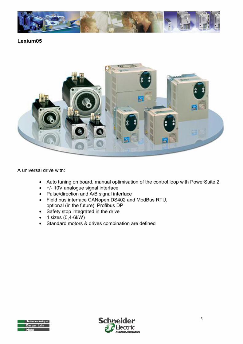
Lexium05
A universal drive with:
• Auto tuning on board, manual optimisation of the control loop with PowerSuite 2 • +/- 10V analogue signal interface • Pulse/direction and A/B signal interface • Field bus interface CANopen DS402 and ModBus RTU,
optional (in the future): Profibus DP • Safety stop integrated in the drive • 4 sizes (0,4-6kW) • Standard motors & drives combination are defined
4
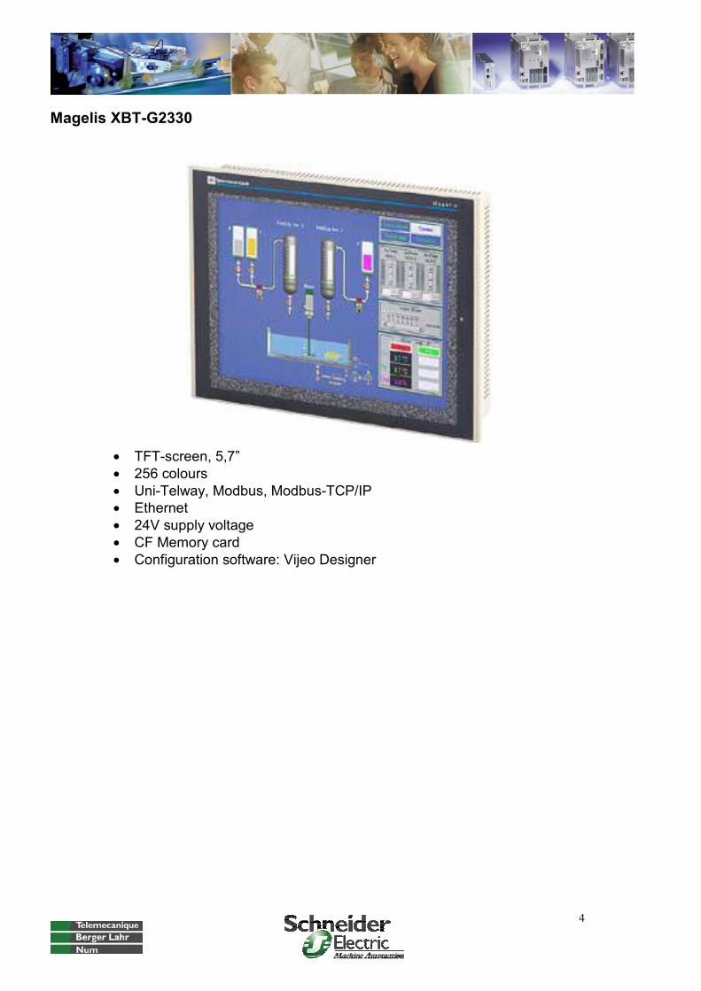
Magelis XBT-G2330
• TFT-screen, 5,7” • 256 colours • Uni-Telway, Modbus, Modbus-TCP/IP • Ethernet • 24V supply voltage • CF Memory card • Configuration software: Vijeo Designer
5
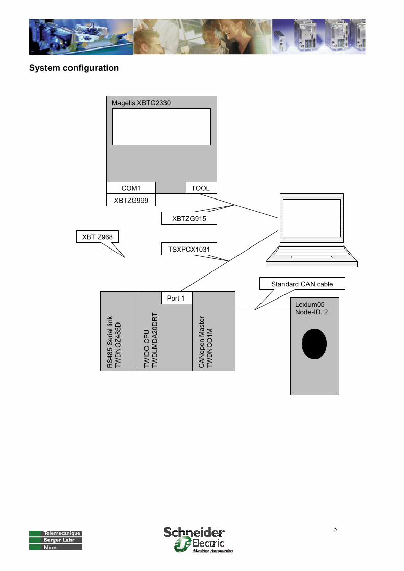
System configuration
TWID
OC
PUTW
DLM
DA
20D
RT
CA
Nop
enM
aste
rTW
DN
CO
1M
RS4
85Se
riall
ink
TWD
NO
Z485
D
Magelis XBTG2330
COM1 TOOL
Lexium05 Node-ID. 2
XBTZG999
Port 1
XBT Z968
XBTZG915
TSXPCX1031
Standard CAN cable

6
Visualization
Typical screen structure
Button FunctionTrend Trend display of the velocity Fault Fault page (only visible if a fault is active)
Main Main page with actual and set values Home Homing mode Set Pos Set position mode Vel Profile velocity mode PtP Point to point mode, manual mode Para Read parameter and write parameter Quit Quit drive error Save Para Saving the Magelis parameter values on the plc
Switch to Trend screen
Display of Actual and set values
Parameter (Read and write
values)
Switchboard
Name of Screen
Switch to Fault screen (appears only when a fault is active)
Action buttons
7
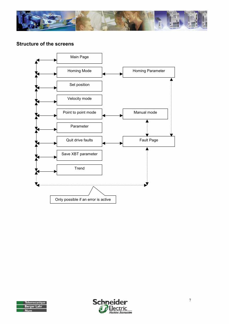
Structure of the screens
Main Page
Homing Mode
Save XBT parameter
Homing Parameter
Manual mode
Set position
Quit drive faults
Parameter
Velocity mode
Point to point mode
Fault Page
Only possible if an error is active
Trend

8
Software
Hardware configuration
At first, the CANopen Master must be added on the extension bus (see also the Twido software reference guide). Then the eds-file of Lexium05 must be imported in the CANopen configuration tool. In this example a Lexium05 is used with node-id 2.
Import EDS
Insert Slaves
Edit Slave-Address
Supervision
Baud rate
9
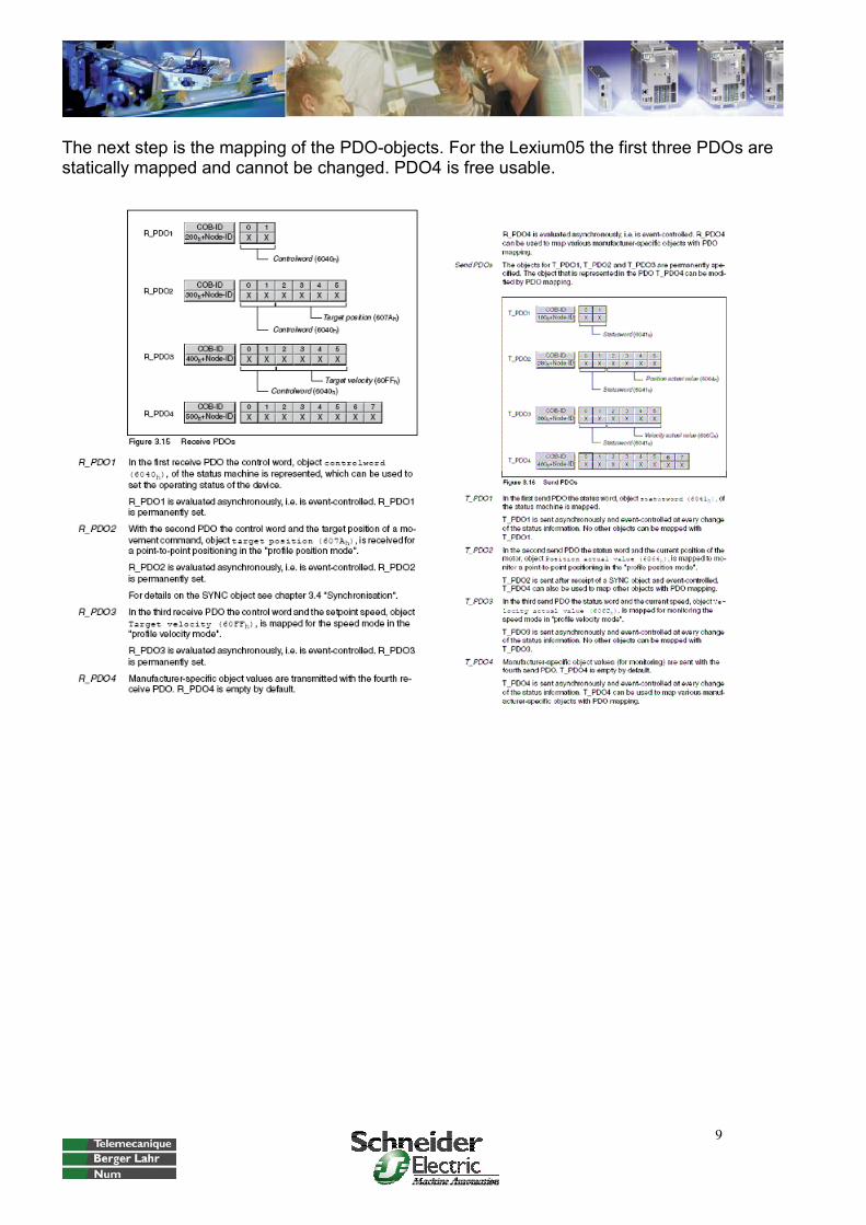
The next step is the mapping of the PDO-objects. For the Lexium05 the first three PDOs are statically mapped and cannot be changed. PDO4 is free usable.

10
List of Objects
Object indices
Transmission/ReceptionCOB-ID

11
After the mapping the objects must be linked with the PLC.
Slave-PDO Master-PDO Transmission/ReceptionInsert

12
Finally the linked objects get symbols.
Symbols Object-name PLC-Address

13
Internal memory words
The following table shows the used internal memory words
Group Subroutine Names of the variables Type Address Comment
Internal Bits Internal Type Address
Internal help flag Bool % M20
Internal help flag HF_00 Bool % M200 Internal help flag HF_01 Bool % M201 Internal help flag HF_02 Bool % M202 Internal help flag HF_03 Bool % M203 Internal help flag HF_04 Bool % M204 Internal help flag HF_05 Bool % M205 Internal help flag HF_06 Bool % M206 Internal help flag HF_07 Bool % M207 Internal help flag HF_08 Bool % M208 Internal help flag HF_09 Bool % M209 Internal help flag HF_10 Bool % M210 Internal help flag HF_11 Bool % M211 Internal help flag HF_12 Bool % M212 Internal help flag HF_13 Bool % M213 Internal help flag HF_14 Bool % M214 Internal help flag HF_15 Bool % M215
System signalsFirst_cyle_in_ run S13 Restore_ memory S95
Backup_OK S96
PLC_Status SW6
Slave_Status SW20 Number_of_ words_to_ save SW97
Config_ok SW81:X0 Data_ exchange_on SW81:X1 System_ stopped SW81:X2 Can_cmd_ done SW81:X3 Can_cmd_ fault SW81:X4 Fault_ initialization SW81:X5 Save_memory_words SW96:X0
Application_ok SW96:X6

14
Magelis XBT XBT to Twido Twido to XBT Type
XBT Start_Homing Bool % MW100:X0
Start_Setpos Bool % MW100:X1
Start_Velmode Bool % MW100:X2
PTP_absolute Bool % MW100:X3
Start_PTP Bool % MW100:X4
Start_Para_Read Bool % MW100:X5
Start_Para_Write Bool % MW100:X6
Quit_Drive_Fault Bool % MW100:X7
Setpos_absolute Bool % MW100:X8
Stop_Velmode Bool % MW100:X9
Read_Error-Code Bool % MW100:X10
Save_OK Bool % MW100:X11
Save Bool % MW100:X12
Restore Bool % MW100:X13
Start_man_right_slow Bool % MW101:X0
Start_man_right_fast Bool % MW101:X1
Start_man_left_slow Bool % MW101:X2
Start_man_left_fast Bool % MW101:X3
Actpos Dint % MD102
Actvel Dint % MD104
Setpos Dint % MD106
Setvel Dint % MD108
Home_Type Int % MW110
Home_Axis Int % MW111
Home_Homepos Dint % MD112
Home_VHome Int % MW114
Home_VOutHome Int % MW115
Home_POutHome Dint % MD116
Home_PDisHome Dint % MD118
Setpos_Pos Dint % MD130
Setpos_Axis Int % MW132
Vel_Setspeed Dint % MD140
Vel_Axis Int % MW142
PTP_Setpos Dint % MD150
PTP_Setspeed Int % MW152
PTP_Axis Int % MW153
Pararead_Index Int % MW160
Pararead_Subindex Int % MW161
Pararead_Axis Int % MW162
Pararead_Data Int % MD164
Parawrite_Index Int % MW170
Parawrite_Subindex Int % MW171
Parawrite_Length Int % MW172
Parawrite_Data Dint % MD174
Parawrite_Axis Int % MW176
Error Dint % MD178
Fault_Homing Bool % MW180:X0
Fault_Setpos Bool % MW180:X1
15
Fault_Move_Vel Bool % MW180:X2
Fault_PTP Bool % MW180:X3
Fault_Read_Para Bool % MW180:X4
Fault_Write_Para Bool % MW180:X5
Fault_Move_Manual Bool % MW180:X6
Fault_Drive Bool % MW180:X7
Manual_Slow Int % MW182
Manual_Fast Int % MW183
Manual_Axis Int % MW184
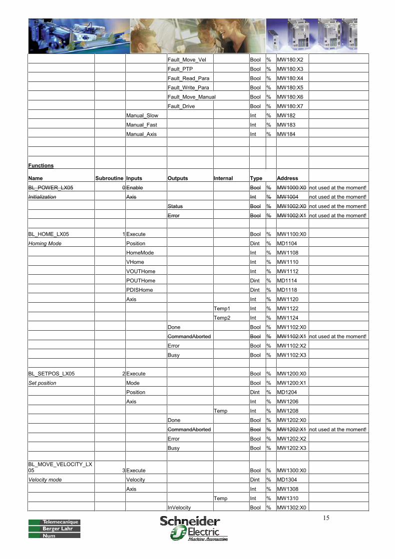
Functions
Name Subroutine Inputs Outputs Internal Type Address
BL_POWER_LX05 0 Enable Bool % MW1000:X0 not used at the moment!
Initialization Axis Int % MW1004 not used at the moment!
Status Bool % MW1002:X0 not used at the moment!
Error Bool % MW1002:X1 not used at the moment!
BL_HOME_LX05 1 Execute Bool % MW1100:X0
Homing Mode Position Dint % MD1104
HomeMode Int % MW1108
VHome Int % MW1110
VOUTHome Int % MW1112
POUTHome Dint % MD1114
PDISHome Dint % MD1118
Axis Int % MW1120
Temp1 Int % MW1122
Temp2 Int % MW1124
Done Bool % MW1102:X0
CommandAborted Bool % MW1102:X1 not used at the moment!
Error Bool % MW1102:X2
Busy Bool % MW1102:X3
BL_SETPOS_LX05 2 Execute Bool % MW1200:X0
Set position Mode Bool % MW1200:X1
Position Dint % MD1204
Axis Int % MW1206
Temp Int % MW1208
Done Bool % MW1202:X0
CommandAborted Bool % MW1202:X1 not used at the moment!
Error Bool % MW1202:X2
Busy Bool % MW1202:X3
BL_MOVE_VELOCITY_LX05 3 Execute Bool % MW1300:X0
Velocity mode Velocity Dint % MD1304
Axis Int % MW1308
Temp Int % MW1310
InVelocity Bool % MW1302:X0

16
CommandAborted Bool % MW1302:X1 not used at the moment!
Error Bool % MW1302:X2
Busy Bool % MW1302:X3
BL_MOVE_PTP_LX05 4 Execute Bool % MW1400:X0
Point to Point: absolute + relative Absolute Bool % MW1400:X1
Position Dint % MD1404
Velocity Int % MW1408
Axis Int % MW1410
Temp Int % MW1412
Done Bool % MW1402:X0
CommandAborted Bool % MW1402:X1 not used at the moment!
Error Bool % MW1402:X2
Busy Bool % MW1402:X3
BL_READ_PARAMETER 5 Enable Bool % MW1500:X0
Read Parameter Index Int % MW1504
Subindex Int % MW1506
Axis Int % MW1508
Done Bool % MW1502:X0
Error Bool % MW1502:X1
Busy Bool % MW1502:X2
Value Dint % MD1510
Length Int % MW1512
BL_WRITE_PARAMETER 6 Execute Bool % MW1600:X0
Write Parameter Value Dint % MD1604
Index Int % MW1608
Subindex Int % MW1610
Length Int % MW1612
Axis Int % MW1614
Done Bool % MW1602:X0
Error Bool % MW1602:X1
Busy Bool % MW1602:X2
BL_MOVE_MANUAL_LX05 7 Execute Bool % MW1700:X0
Manual movement Right_slow Bool MW1700:X0
Right_fast Bool MW1700:X1
Left_slow Bool MW1700:X2
Left_fast Bool MW1700:X3
Vel_Slow Int % MW1704
Vel_Fast Int % MW1706
Axis Int % MW1708
Done Bool % MW1702:X0
Error Bool % MW1702:X1
Busy Bool % MW1702:X2
Temp Int % MW1710

17
Overview of the application:
Name Rung Backup of the internal memory words 0-3 Initialization 4-8 Fault reset, application reset, helpflag reset 9-11 Data Exchange Twido -> Magelis XBT 12-20 Call Subroutines 21-33 Subroutine 1: Homing 34-74 Subroutine 2: Set position 75-98 Subroutine 3: Velocity mode 99-116 Subroutine 4: Point to point mode 117-136 Subroutine 5: Read Parameter 137-141 Subroutine 6: Write Parameter 142-146 Subroutine 7: Manual mode 147-171
Backup of the internal memory words (rung0-3)
After the first software download to the plc the contents of all memory words is zero. Some default values for those memory words are stored in the animation table “V100_XBT.tat”. Download them and start a backup (description see below). Now it is possible to save and restore the actual settings with the HMI. Here an example: Go to page “Vel” Change the parameter “Set speed” to 1111 Go to page “Save Para” Press the button “Save XBT parameter” (the button is green if it is possible) Go to page “Vel” Change the parameter “Set speed” to 2222 Go to page “Save Para” Press the button “Restore XBT parameter” Go to page “Vel” The parameter “Set speed” is 1111

18
The Online help of Twidosoft describes how to save data in the internal EEPROM:

19
Here is the description of the system bits (source: online help):
%S97 is true after the memory words are saved without an error. In the application it is not used.
Here is the description of the system words (source: online help):

20
%SW96:X6 is true if the application is ok.
%SW97 is the number of words to be saved, starting with %MW0. In the application the value is 185, because the highest memory word of the Magelis XBT-interface is %MW184.
21
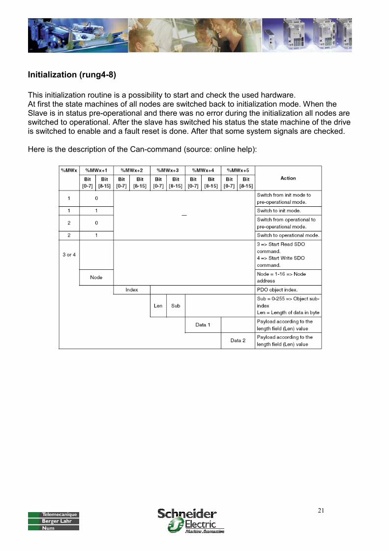
Initialization (rung4-8)
This initialization routine is a possibility to start and check the used hardware. At first the state machines of all nodes are switched back to initialization mode. When the Slave is in status pre-operational and there was no error during the initialization all nodes are switched to operational. After the slave has switched his status the state machine of the drive is switched to enable and a fault reset is done. After that some system signals are checked.
Here is the description of the Can-command (source: online help):
22
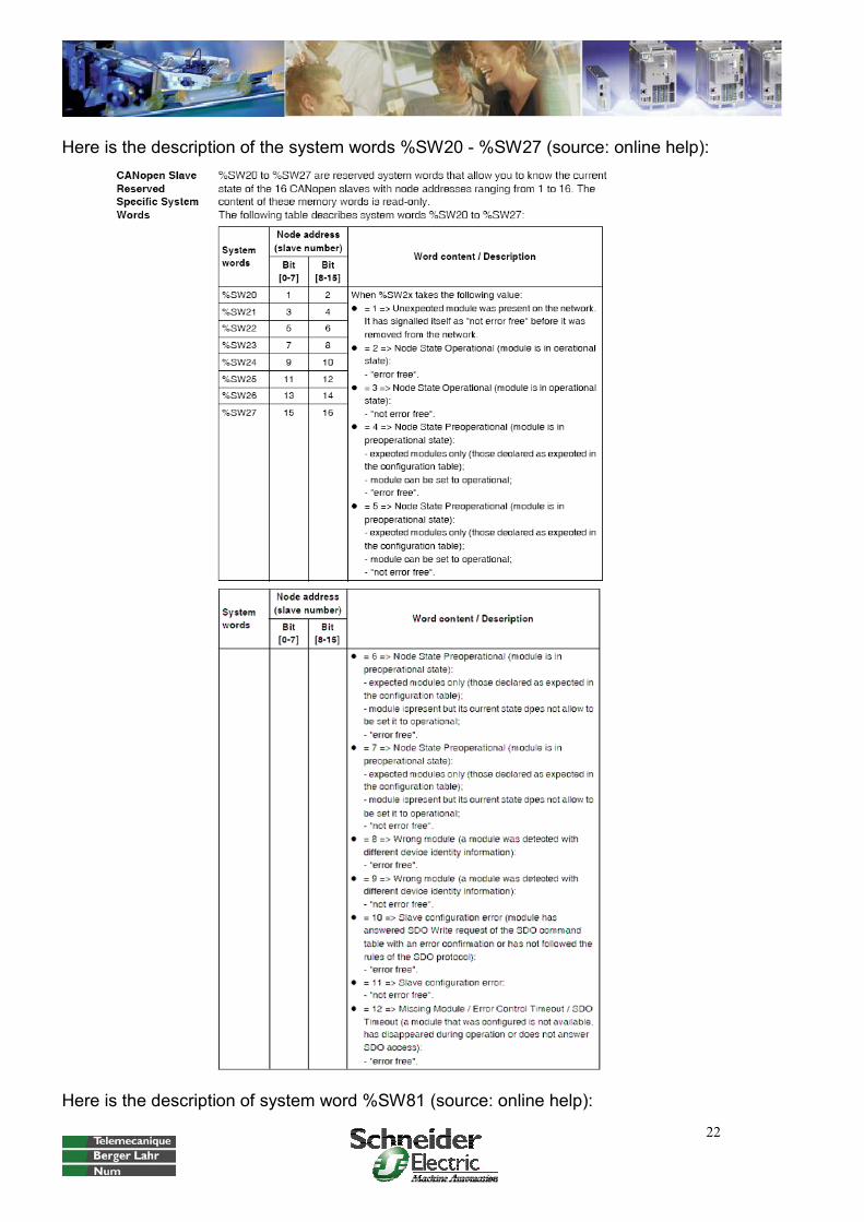
Here is the description of the system words %SW20 - %SW27 (source: online help):
Here is the description of system word %SW81 (source: online help):

23
Here is the description of system word %SW6 (source: online help):
Fault reset, application reset and helpflag reset (rung 9-11)
In rung 9 the reset bit is sent from the HMI to the drive. To reset the applications it is necessary to reset the busy-signals from the subroutines. The helpflags %M200-%M215 are used in the subroutines and get a reset every cycle.
Data exchange Twido->Magelis XBT (rung 12-20)
In these rungs the errors, the actual and set values of position and speed are sent from the Twido to the HMI.
24
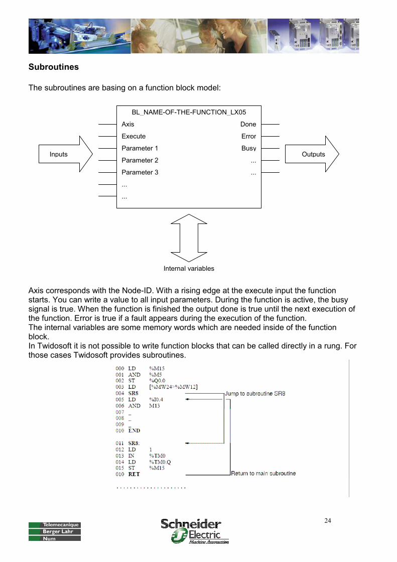
Subroutines
The subroutines are basing on a function block model:
Axis corresponds with the Node-ID. With a rising edge at the execute input the function starts. You can write a value to all input parameters. During the function is active, the busy signal is true. When the function is finished the output done is true until the next execution of the function. Error is true if a fault appears during the execution of the function. The internal variables are some memory words which are needed inside of the function block. In Twidosoft it is not possible to write function blocks that can be called directly in a rung. For those cases Twidosoft provides subroutines.
Axis
...
Execute
Parameter 1
Parameter 2
...
Parameter 3
Done
Error
Busy
BL_NAME-OF-THE-FUNCTION_LX05
Inputs Outputs...
...
Internal variables

25
Homing mode (rung 34-74; function call in rung 21-22)
Name Subroutine Inputs Outputs Internal Type Address Comment
BL_HOME_LX05 1 Execute Bool % MW1100:X0 Start of the movement
Homing Mode Position Dint % MD1104 Position on reference point
HomeMode Int % MW1108 Type of reference run
VHome Int % MW1110 Speed for search for the switch
VOUTHome Int % MW1112 Speed for retraction from switch
POUTHome Dint % MD1114 Maximum run-off distance
PDISHome Dint % MD1118
Maximum search distance after traversing over the switch
Axis Int % MW1120 Node-ID
Temp1 Int % MW1122
Temp2 Int % MW1124
Done Bool % MW1102:X0
CommandAborted Bool % MW1102:X1 not used at the moment!
Error Bool % MW1102:X2
Busy Bool % MW1102:X3
The homing mode is a standardised operation mode. Generally, to activate it the parameter operation mode (6060:0h) must be set to 06h. Then, after the reading of the actual operation mode (6061:0h) the reference type must be set (6098:0h). To start the movement the bit number 4 in the control word PDO1 must be true. The status word gives detailed status information.
Axis
POutHome
Execute
Position
Home mode
VOutHome
VHome
Done
Error
Busy
BL_HOME_LX05
PDisHome

26
The CAN open technical documentation describes also the activation of the operation mode (source: Lexium05 CANopen documentation):
The NMT command Start Remote node is done automatically during the initialization of the bus. The activation of the power circuit happens in rung 7.

27
In the program example the function block BL_HOME_LX05 is called in the rung 21-22. In rung 21 the values from the HMI are connected with the function inputs. In rung 22 is the function call of subroutine 1. It is active as long as the busy-bit is true.
Generally, the subroutines are programmed as a sequence using the internal memory words. For example the bit %MW1122:X0 sets the bit %MW1122:X1, the bit %MW1122:X1 sets the bit %MW1122:X2, and so on. The last bit resets them all.
The subroutine starts in rung 34. Rung 35 is the initialization of the internal and output signals. Rung 36-37 writes parameter Position after reference (3028:Bh). When the data transfer on the Can bus is in progress, the system bit %SW81:X3 is false (rung 38). When the data transfer is done that bit is true again (rung 38). Then it is possible to write the next parameters Vhome (6099:1h), VoutHome (6099:2h), PoutHome (3028:6h) and PdisHome(3028:Dh) (rung 40-55). Now, as the technical documentation describes, the operation mode must be started by writing parameter 6060:0h with 6h (rung 56-59). After that the operation status must be checked by reading parameter 6061:0h. The contents must be 6h (rung60-63). In the rungs 64-67 the parameter reference movement method 6098:0h is transmitted and the start bit in the control word is set to false. Rung 69 starts the movement by setting the start bit directly in the control word. Rung 70-71 is the end of the operation mode. Therefore the information of the status word are used (source: Lexium05 documentation):
If everything is ok, the busy output is false, the done output is true, the internal help flags get a reset and also the start bit in the control word. When an error appears during that movement, an alarm bit is true and the function gets a complete reset (rung 72-73). With the return in rung 74 the subroutine is finished and the program continues in the main program.
28
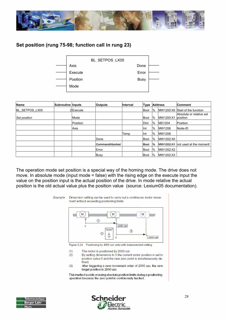
Set position (rung 75-98; function call in rung 23)
Name Subroutine Inputs Outputs Internal Type Address Comment
BL_SETPOS_LX05 2 Execute Bool % MW1200:X0 Start of the function
Set position Mode Bool % MW1200:X1Absolute or relative set position
Position Dint % MD1204 Position
Axis Int % MW1206 Node-ID
Temp Int % MW1208
Done Bool % MW1202:X0
CommandAborted Bool % MW1202:X1 not used at the moment!
Error Bool % MW1202:X2
Busy Bool % MW1202:X3
The operation mode set position is a special way of the homing mode. The drive does not move. In absolute mode (input mode = false) with the rising edge on the execute input the value on the position input is the actual position of the drive. In mode relative the actual position is the old actual value plus the position value (source: Lexium05 documentation).
Axis
Execute
Position
Mode
Done
Error
Busy
BL_SETPOS_LX05

29
Velocity mode (rung 99-116; function call in rung 24)
Name Subroutine Inputs Outputs Internal Type Address Comment
BL_MOVE_VELOCITY_LX05 3 Execute Bool % MW1300:X0 Start of the movement
Velocity mode Velocity Dint % MD1304 Set speed
Axis Int % MW1308 Node-ID
Temp Int % MW1310
InVelocity Bool % MW1302:X0 Set speed reached
CommandAborted Bool % MW1302:X1 not used at the moment!
Error Bool % MW1302:X2
Busy Bool % MW1302:X3
In the profile velocity mode the drive is accelerated to an adjustable setpoint speed. When it is reached the output InVelocity is true. To stop the operation mode, the set speed must be zero. The profile velocity mode is also a standardised operation mode. Generally, to activate it the parameter operation mode (6060:0h) must be set with 03h. Then, after the reading of the actual operation mode (6061:0h) the movement starts by writing a set value directly to the target velocity on PDO3. The status word gives detailed information.
In the program example the function block BL_MOVE_VELOCITY_LX05 is called in rung 24.
The subroutine starts in rung 99. Rung 100 is the initialization of the internal and output signals. The operation mode must be started by writing parameter 6060:0h with 3h (rung 101-104). After that the operation status must be checked by reading parameter 6061:0h. The contents must be 3h (rung105-108). In rung 109 the movement starts if the set speed is different from zero, otherwise it stops. Rung 110 generates a help flag if the set speed is zero. Rung 111 is the end of the operation mode depending on the information of the status word. Rung 112 is necessary to delay the execution of rung 111. Rung 113 writes the output InVelocity. When an error appears during that movement, an alarm bit is true and the function gets a complete reset (rung 114-115). With the return in rung 116 the subroutine is finished and the program continues in the main program.
Axis
Execute
Velocity
InVelocity
Error
Busy
BL_MOVE_VELOCITY_LX05

30
Here are the information from the status word (source: Lexium05 documentation):

31
The CAN open technical documentation describes also the activation of the operation mode:
The enabling of the PDO is done automatically during the initialization of the bus, also the NMT command Start Remote node. The activation of the power circuit happens in rung 7. To set the acceleration ramp, deceleration ramp and restrict setpoint speed is optional.

32
Point to point mode (rung 117-136; function call in rung 25)
Name Subroutine Inputs Outputs Internal Type Address Comment
BL_MOVE_PTP_LX05 4 Execute Bool % MW1400:X0 Start movement
Point to Point: absolute + relative Absolute Bool % MW1400:X1
Relative (false) or absolute (true) position mod
Position Dint % MD1404 Target position
Velocity Int % MW1408 Set speed for the movement
Axis Int % MW1410 Node-ID
Temp Int % MW1412
Done Bool % MW1402:X0
CommandAborted Bool % MW1402:X1 not used at the moment!
Error Bool % MW1402:X2
Busy Bool % MW1402:X3
In the point to point operating mode the drive makes a relative or absolute positioning with a adjustable speed. The profile point to point mode is also a standardised operation mode. Generally, to activate it the parameter operation mode (6060:0h) must be set with 01h. Then, after the reading of the actual operation mode (6061:0h) the movement starts by setting the bits in the control word of PDO2. The status word gives detailed information.
In the program example the function block BL_MOVE_VELOCITY_LX05 is called in rung 25.
The subroutine starts in rung117. Rung 118 is the initialization of the internal and output signals. In rung 119-122 the set speed (6081:0h) is set. The operation mode must be started by writing parameter 6060:0h with 1h (rung 123-126). After that the operation status must be checked by reading parameter 6061:0h (rung127-130). In the rungs 131-132 the set position is set in the target position in PDO2. Depending on the setting of the bits in the control word of PDO 2 the movement starts (in this program example Bit 5 is not used; source: Lexium05 documentation).
Axis
Execute
Velocity
InVelocity
Error
Busy
BL_MOVE_PTP_LX05
Position

33
Rung 133 is the end of the operation mode depending on the information of the status word. When an error appears during that movement, an alarm bit is true and the function gets a complete reset (rung 134-135). With the return in rung 136 the subroutine is finished and the program continues in the main program (source: Lexium05 documentation).

34
Read parameter (rung 137-141; function call in rung 26)
Name Subroutine Inputs Outputs Internal Type Address Comment
BL_READ_PARAMETER 5 Enable Bool % MW1500:X0 Start function
Read Parameter Index Int % MW1504 Parameter index
Subindex Int % MW1506 Parameter subindex
Axis Int % MW1508 Node-ID
Done Bool % MW1502:X0
Error Bool % MW1502:X1
Busy Bool % MW1502:X2
Value Dint % MD1510 Data value
Length Int % MW1512
This function reads a parameter from the drive. In the program example the function block is called in rung 26. In rung 27 the output value is copied to the HMI-variables.
The subroutine starts in rung 137. In rung 138 is the read operation. Rung 139 sets the output done and rung 140 copies the value to the output. Rung 141 is the end of the subroutine.
Rung 27-28 reads the error code of the drive (603F:0) and copies the value to the HMI. This is an example how to use the functions.
Axis
Enable
Index
Done
Error
Busy
BL_READ_PARA_LX05
Subindex Value

35
Write parameter (rung 142-145; function call in rung 30)
Name Subroutine Inputs Outputs Internal Type Address Comment
BL_WRITE_PARAMETER 6 Execute Bool % MW1600:X0 Start function
Write Parameter Value Dint % MD1604 Value to write
Index Int % MW1608 Parameter index
Subindex Int % MW1610 Parameter subindex
Length Int % MW1612 Parameter length in byte
Axis Int % MW1614 Node-ID
Done Bool % MW1602:X0
Error Bool % MW1602:X1
Busy Bool % MW1602:X2
This function writes a parameter to the drive. In the program example the function block is called in rung 30.
The subroutine starts in rung 142. In rung 143 is the write operation. Rung 144 sets the output done and rung 145 is the end of the subroutine.
Important is the correct data length. Otherwise the operation does not work.
Axis
Execute
Value
Done
Error
Busy
BL_WRITE_PARA_LX05
Subindex
Index
Length
36
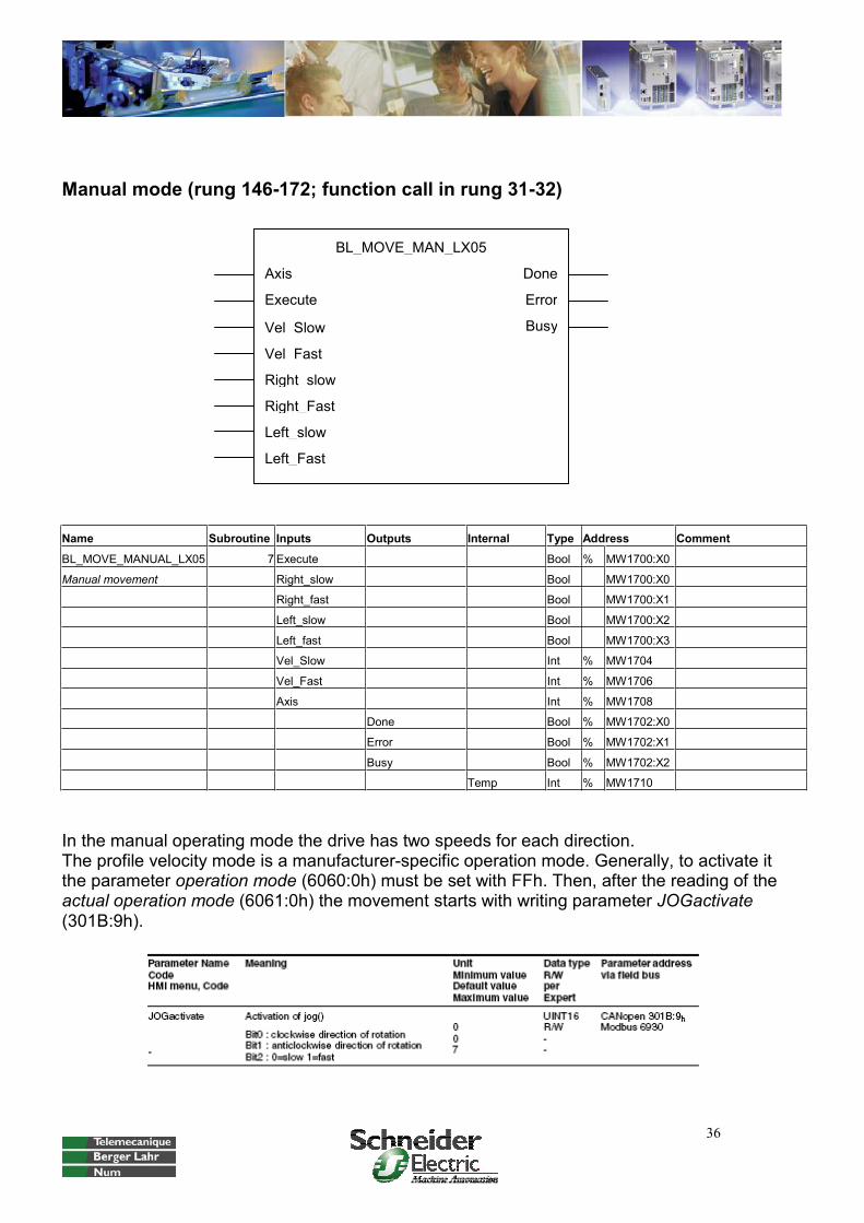
Manual mode (rung 146-172; function call in rung 31-32)
Name Subroutine Inputs Outputs Internal Type Address Comment
BL_MOVE_MANUAL_LX05 7 Execute Bool % MW1700:X0
Manual movement Right_slow Bool MW1700:X0
Right_fast Bool MW1700:X1
Left_slow Bool MW1700:X2
Left_fast Bool MW1700:X3
Vel_Slow Int % MW1704
Vel_Fast Int % MW1706
Axis Int % MW1708
Done Bool % MW1702:X0
Error Bool % MW1702:X1
Busy Bool % MW1702:X2
Temp Int % MW1710
In the manual operating mode the drive has two speeds for each direction. The profile velocity mode is a manufacturer-specific operation mode. Generally, to activate it the parameter operation mode (6060:0h) must be set with FFh. Then, after the reading of the actual operation mode (6061:0h) the movement starts with writing parameter JOGactivate(301B:9h).
Axis
Execute
Vel_Slow
Done
Error
Busy
BL_MOVE_MAN_LX05
Vel_Fast
Right_slow
Right_Fast
Left_slow
Left_Fast

37
In the program example the function block BL_MOVE_MAN_LX05 is called in rung 31-32.
The subroutine starts in rung 146. Rung 147 is the initialization of the internal and output signals. In rung 148-151 the slow speed (3029:4h) is set, in rung 152-155 the fast speed(3029:5h). The operation mode must be started with writing parameter 6060:0h with FFh (rung 156-159). After that the operation status must be checked by reading parameter 6061:0h. The contents must be FFh (rung160-163). In rung 164 the movement starts in the right direction. In rung 165 the movement starts in the left direction. Rung 166 is necessary to stop the drive. When the movement has started the signal X_END in the status word is false (rung 167). When all of the four input bits are false and the X_END is true again the operation mode is finished rung 168). Rung 169 is for the error bit. The reset of the function is disabled. This is necessary if the manual should work although an error is active, for example to move the drive in the right direction from left limit switch. With the return in rung 171 the subroutine is finished and the program continues in the main program.
Summary
This application shows one possibility how to activate different operation modes at one drive, using the subroutines and memory words. It would be also possible to activate the modes using a sequence, step counter, … To use more drives is possible, but the software needs to be extended with the input and output variables of the further drives. This application does not use all available operation modes. There are some more, for example the current control mode. To use this example it is also necessary to use the Lexium05 device manual and the Lexium05 CANopen manual.
Designed 16.09.2005 by
Patrick FriedmannBerger Lahr GmbH
Customer Support Center - Technical SupportGewerbestraße 9
D-77749 Hohberg-Niederschopfheim. Tel.: +49 7808 / 943-235
Fax: +49 7808 / 946-58 235 E-Mail: mailto:[email protected]
www.berger-lahr.com