tutorial for simulation of electric actuators - ipcoipco-co.com/pet_journal/presented...
TRANSCRIPT

Tutorial for simulation of electric actuators Dhaoui Mehdi1, Sbita Lassaad2
Electrical Engineering Department, National Engineering School of Gabes (ENIG) Gabes, Tunisia
Street Omar Ibn Elkhattab 6029, Gabes,Tunisia [email protected]
Abstract— Tutorial TSIM_EA simulation (Tutorial SIMulation for Electric Actuators) is an educational simulation tool dedicated to the identification, modeling and control of electric actuators, mainly three phase induction motors. The proposed Tutorial is a set of interactive graphical interfaces allowing the user to easily switch from one menu to another and choose the topic to be studied. Different interfaces are related to program Matlab and Simulink. It has three main themes (Automatic, power electronics and control of machines). It can be used with a PC with at least a 256 MB RAM capacity and with the MATLAB / SIMULINK environment, at least version 7.4.0.
Keywords— Tutorial, Electric Actuators, Simulation, Control, Fuzzy Logic, Neural Networks, Genetic Algorithm.
I. INTRODUCTION
Simulation is an essential step before starting the experimental phase. It is a necessary tool before any practical implementation. The study of any physical system usually requires modeling. This allows to simulate the behavior of the system to various stresses and to understand the mechanism and its operation.
The simulation step thus allows the user to draw at least revealing ideas or partial response, even if they are flawed, what is really happening in the physical system. Thanks to the simulation, we can evaluate our approach and direct our powers based on the results we get.
Tutorial TSIM_EA proposed uses interactive graphical interfaces to easily switch from one menu to another and choose the topic to be studied. Different interfaces are related to MATLAB/Simulink. It has three main themes (Automatic, power electronics and control of machines).
We are interested in this work to the menu of electrical machines. This menu contains three themes structured in a pedagogical way, the identification, modeling and control of induction motor. Other menus are also available to the user; energy optimization and adaptation of the rotor resistance in an asynchronous machine.
Fig 1. General Menu
II. INTERFACES OF ELECTRICAL MACHINES
A. Identification of parameters
The identification of parameters can be obtained by conventional method, by Genetic Algorithm or by Neural Networks.
A.1. Conventional Method To identify the parameters of the induction machine, the
user must:
•••• Choose the method of identification.
•••• Enter the data plate of the machine.
•••• Choose the connection type and class of machine.
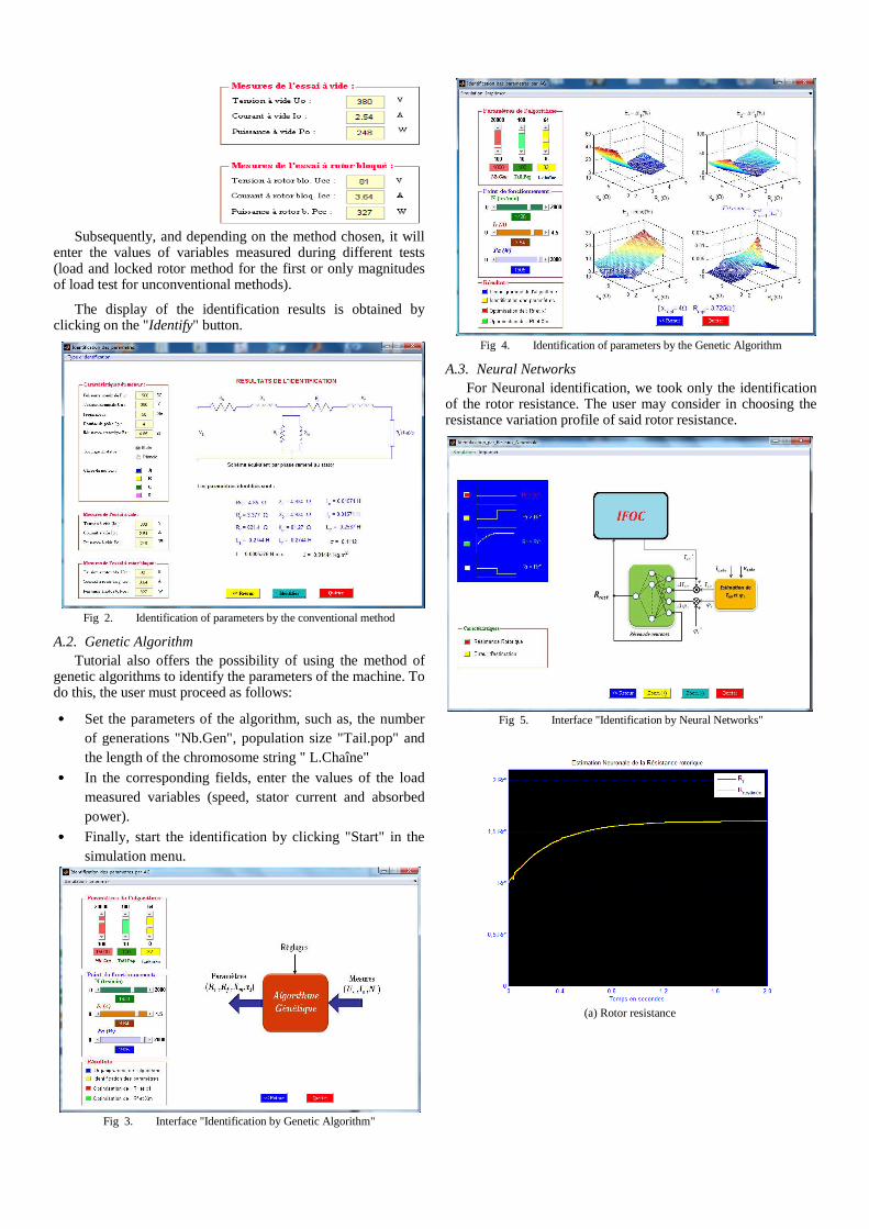
Subsequently, and depending on the method chosen, it will
enter the values of variables measured during different tests (load and locked rotor method for the first or only magnitudes of load test for unconventional methods).
The display of the identification results is obtained by clicking on the "Identify" button.
Fig 2. Identification of parameters by the conventional method
A.2. Genetic Algorithm Tutorial also offers the possibility of using the method of
genetic algorithms to identify the parameters of the machine. To do this, the user must proceed as follows:
•••• Set the parameters of the algorithm, such as, the number of generations "Nb.Gen", population size "Tail.pop" and the length of the chromosome string " L.Chaîne"
•••• In the corresponding fields, enter the values of the load measured variables (speed, stator current and absorbed power).
•••• Finally, start the identification by clicking "Start" in the simulation menu.
Fig 3. Interface "Identification by Genetic Algorithm"
Fig 4. Identification of parameters by the Genetic Algorithm
A.3. Neural Networks For Neuronal identification, we took only the identification
of the rotor resistance. The user may consider in choosing the resistance variation profile of said rotor resistance.
Fig 5. Interface "Identification by Neural Networks"
(a) Rotor resistance

(b) Estimation error
Fig 6. Estimation of rotor resistance
B. Modeling of the machine
Tutorial allows the user to get the machine model under either static or dynamic (Static model, Dynamic Model)
Fig 7. Interface « Modeling the machine »
B.1. Static model The static model is based on the analysis of the equivalent
circuit of the machine in continuous operation. The user must enter the parameters of the machine. For study and display variables brought into play for a given operating point, he must choose the corresponding slip value.
Fig 8. Menu "Static modeling of the machine"
The display of different characteristics is obtained by clicking on "Tracing characteristics."
Fig 9. Display characteristics versus slip
B.2. Dynamic Model The study offers four dynamic model types. Tutorial allows
the user to consider whether some physical phenomena such as saturation and iron losses. It may also involve some simplifying assumptions.
Fig 10. Comparison of nominal and saturated models (eg RMS stator
current)
The simple model does not account for the phenomena mentioned above. It is based on the PARK transformation in a reference system related to the rotating field, to the stator or to rotor.
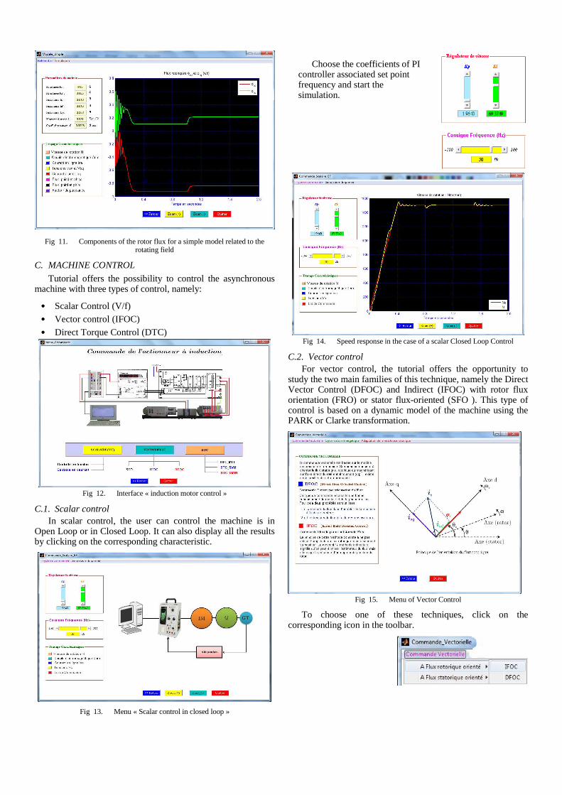
Fig 11. Components of the rotor flux for a simple model related to the rotating field
C. MACHINE CONTROL
Tutorial offers the possibility to control the asynchronous machine with three types of control, namely:
•••• Scalar Control (V/f)
•••• Vector control (IFOC)
•••• Direct Torque Control (DTC)
Fig 12. Interface « induction motor control »
C.1. Scalar control In scalar control, the user can control the machine is in
Open Loop or in Closed Loop. It can also display all the results by clicking on the corresponding characteristic.
Fig 13. Menu « Scalar control in closed loop »
Fig 14. Speed response in the case of a scalar Closed Loop Control
C.2. Vector control For vector control, the tutorial offers the opportunity to
study the two main families of this technique, namely the Direct Vector Control (DFOC) and Indirect (IFOC) with rotor flux orientation (FRO) or stator flux-oriented (SFO ). This type of control is based on a dynamic model of the machine using the PARK or Clarke transformation.
Fig 15. Menu of Vector Control
To choose one of these techniques, click on the corresponding icon in the toolbar.
Choose the coefficients of PI controller associated set point frequency and start the simulation.

Fig 16. Indirect Vector Control menu in Rotor flux oriented
Fig 17. Speed response controlled by the IFOC technical
C.3. Direct Torque Control The direct torque control (DTC) is an alternative of the
vector control. One of the principles of this command is to select at any time of the voltage vector imposed by the power converter to control the torque and flux. This choice is based on the outputs of the hysteresis controllers.
Fig 18. Torque response for DTC control with "sinus-triangle" Modulation
Fig 19. Components (Фrd and Фrq) of the rotor flux for DTC control
D. Energy optimization
In the menu “Energy optimization”, there are two techniques:
• Rotor flux optimization (minimization of total losses)
• stator current optimization (copper loss or total loss minimization)
D.1. Algorithm for rotor flux optimization
This algorithm aims to minimize the total losses actuator by optimizing the rotor flux. The optimal value of the flux, depend on the torque and speed values corresponding to the desired operating point. Both instructions are selected by the user.
Edit the controller parameters, the frequency reference and run the simulation.
Choose the type of modulation to control the associated inverter to the motor, edit the controller parameters and run the simulation.
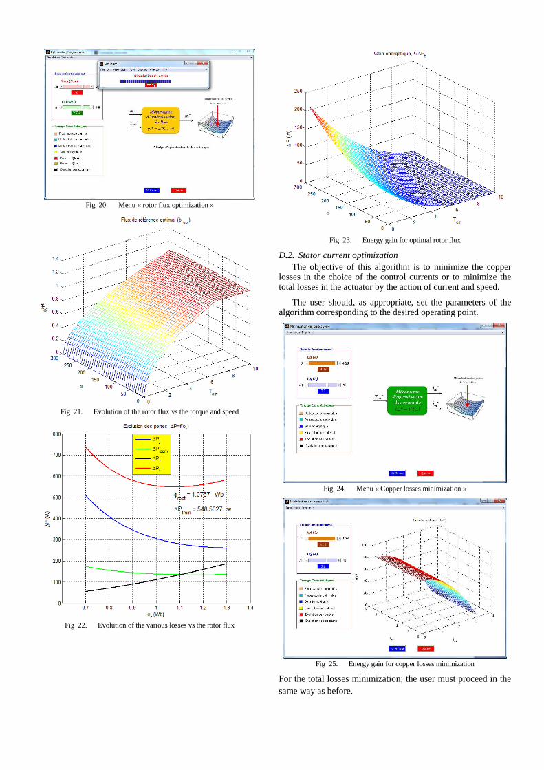
Fig 20. Menu « rotor flux optimization »
Fig 21. Evolution of the rotor flux vs the torque and speed
Fig 22. Evolution of the various losses vs the rotor flux
Fig 23. Energy gain for optimal rotor flux
D.2. Stator current optimization The objective of this algorithm is to minimize the copper
losses in the choice of the control currents or to minimize the total losses in the actuator by the action of current and speed.
The user should, as appropriate, set the parameters of the algorithm corresponding to the desired operating point.
Fig 24. Menu « Copper losses minimization »
Fig 25. Energy gain for copper losses minimization
For the total losses minimization; the user must proceed in the same way as before.
E. Rotor resistance adaptation
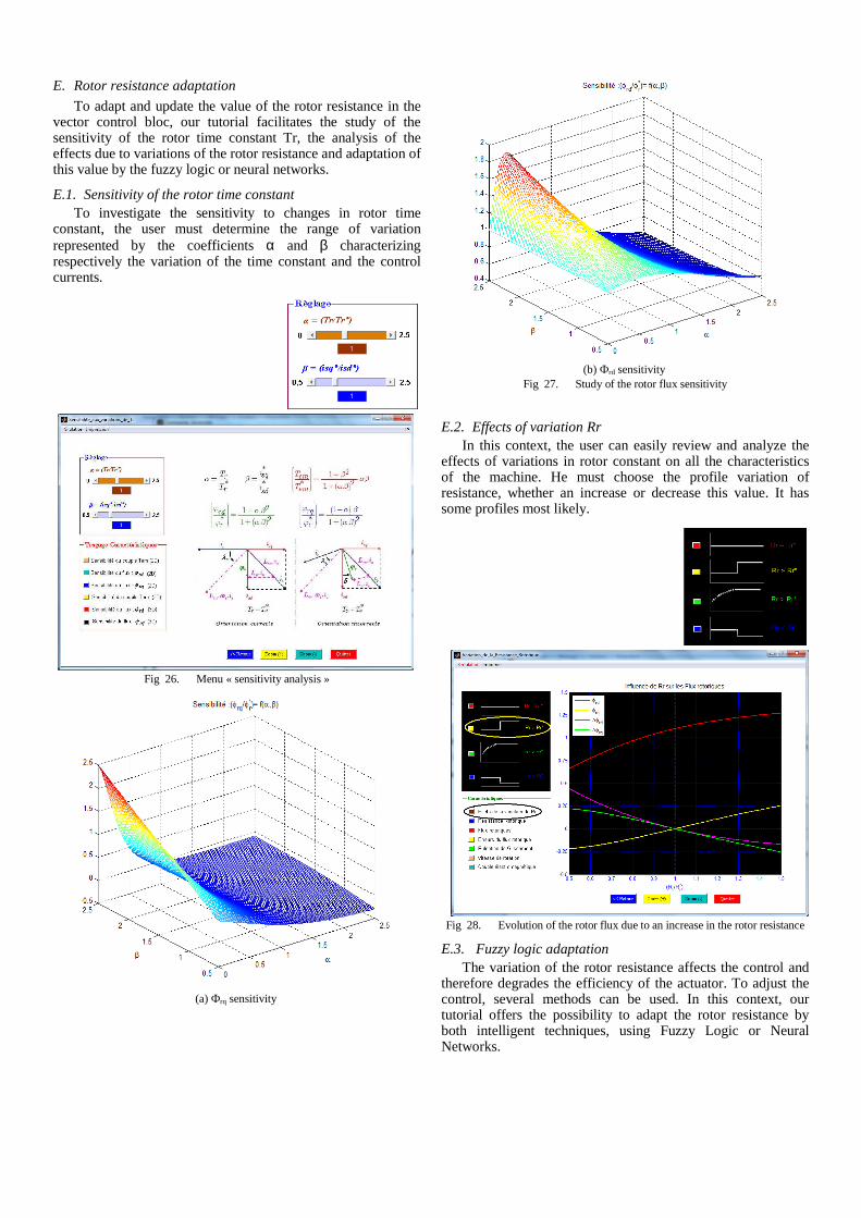
To adapt and update the value of the rotor resistance in the vector control bloc, our tutorial facilitates the study of the sensitivity of the rotor time constant Tr, the analysis of the effects due to variations of the rotor resistance and adaptation of this value by the fuzzy logic or neural networks.
E.1. Sensitivity of the rotor time constant To investigate the sensitivity to changes in rotor time
constant, the user must determine the range of variation represented by the coefficients α and β characterizing respectively the variation of the time constant and the control currents.
Fig 26. Menu « sensitivity analysis »
(a) Фrq sensitivity
(b) Фrd sensitivity
Fig 27. Study of the rotor flux sensitivity
E.2. Effects of variation Rr
In this context, the user can easily review and analyze the effects of variations in rotor constant on all the characteristics of the machine. He must choose the profile variation of resistance, whether an increase or decrease this value. It has some profiles most likely.
Fig 28. Evolution of the rotor flux due to an increase in the rotor resistance
E.3. Fuzzy logic adaptation The variation of the rotor resistance affects the control and
therefore degrades the efficiency of the actuator. To adjust the control, several methods can be used. In this context, our tutorial offers the possibility to adapt the rotor resistance by both intelligent techniques, using Fuzzy Logic or Neural Networks.

Fig 29. Menu « Fuzzy logic adaptation »
(a) Flux errors
(b) slip pulse
Fig 30. Flux errors and rotor slip pulse adaptation in the case of an increase of Rr
E.4. Neural Networks adaptation The problem of adaptation can be also solved using Neural
Networks. On the interface "Neuronal Adaptation of the rotor resistance", the user must follow the same approach of fuzzy logic adaptation.
Fig 31. Menu « Neural Networks adaptation »
III. CONCLUSION
In this paper, the performances of the proposed Tutorial TSIM_EA are tested. Interactive graphical interfaces much easier task for a user wishing to study induction actuator. Indeed, the proposed tutorial, we can both identify, modeling and controlling the actuator using intelligent techniques and then compare the results to those experimental.
REFERENCES [1] D. Mehdi and S. Lassad. A New Method for Losses Minimization in
IFOC Induction Motor Drives. International journal of systems control IJSC, Vol. 1, pp. 93-99, 2010.
[2] F. Aymen, H. Kraiem, M. Dhaoui and L. Sbita. A Recurrent Neural Network Position and High Speed’s Controller of an Induction Motor Drive. International Journal of Research and Reviews in Computer Science, IJRRCS, Vol. 2, n°. 4, pp. 2079-2557, 2011.
[3] H. Kraiem, D. Mehdi and al. Losses Minimization in a DTC-DPWM Induction Motor Drives. International Review on Modeling and Simulations, I.RE.MO.S, Vol. 4. n°.2, pp. 555-561, 2011.
[4] K. Laroussi and al. Implementation of a Fuzzy Logic System to Tune a PI Controller Applied to an Induction Motor", Advances in Electrical and Computer Engineering, Vol. 9, pp. 107-113, 2009.
[5] O. Kuljaca and al. Dynamic focusing of awareness in fuzzy control systems. International Journal of Artificial Intelligence & Applications IJAIA, Vol.2, No.2, pp. 1-19, 2011.
[6] Qu Sun and al. Stable and Optimal Adaptive Fuzzy Control of Complex Systems using Fuzzy Dynamic Model. International journal of Fuzzy Sets and Systems, n° 133, pp. 1 – 17, 2003.
[7] R. Nirali and S.K. Shah. Fuzzy Decision Based Soft Multi Agent Controller for Speed Control of Three Phase Induction Motor. International Journal on Soft Computing IJSC, Vol.2, n°.3, pp. 46-54, 2011.
[8] S. J. Bassi and al. Automatic tuning of proportional–integral–derivative (PID) controller using particle swarm optimization (PSO) algorithm. International Journal of Artificial Intelligence & Applications IJAIA, Vol.2, n°.4, pp. 25-34, 2011.