tutorial eng
TRANSCRIPT

8/6/2019 Tutorial Eng
http://slidepdf.com/reader/full/tutorial-eng 1/57
EAGLE4.0forLinuxâ andWindowsâ
Schematic-Layout-Autorouter
Tutorial
CadSoftComputer,Inc.
www.cadsoftusa.com
Copyright©2000CadSoftAllRightsReserved

8/6/2019 Tutorial Eng
http://slidepdf.com/reader/full/tutorial-eng 2/57
Ifyouhaveanyquestionspleasefeelfreetocontactus:
US Aandothercountries:
Phone: +1(561)2748355,USAalso:1-800-858-8355
Fax: +1(561)2748218
Internet: www.cadsoftusa.com
Email: [email protected]
GermanyandotherEuropeancountries:
Phone: +49(0)86356989-10Hotline: +49(0)86356989-30
Fax: +49(0)86356989-40
Internet: www.cadsoft.de
Email: [email protected]
Andrememberthatweofferafreehotlineforourcustomers!
© Copyright2000CadSoftComputer,Inc.AllrightsreservedworldwideNopartofthispublicationmaybereproduced,storedinaretrievalsystem,ortransmitted,inanyformorbyanymeans,electonic,mechanical,photocopying,recording,scanning,digitizing,orotherwise,withoutthepriorconsenseof CadSoft.
WindowsisaregisteredtrademarkofMicrosoftCorporation.
LinuxisaregisteredtrademarkofLinusTorvalds.

8/6/2019 Tutorial Eng
http://slidepdf.com/reader/full/tutorial-eng 3/57
TableofContents
1WhattoexpectfromthisManual 7
2SystemRequirements 7
3FeaturesofEAGLE 8ProfessionalVersion 8
General 8
LayoutEditor 8
SchematicModule 8
AutorouterModule 9
StandardEdition 9
LightEdition(Freeware) 9
4InstallationandProgramStart 10
Windows 10
Linux 10
5IndividualEAGLESetup 10
6TheConceptoftheEAGLEUserInterface 11
7TypographicConventions 11
SelectingMenuItems 11
MouseClick 11
SeveralInputAlternatives 12
UseofKeyCombinations 12
CommandandParameterInputviatheCommandLine 12
8ControlPanel 15
EAGLEFiles 16EAGLEProjects 16
9LoadFileandSelectMonitorZoom 17
10SelectingLayersforDisplay 18
11SettingupGridandUnit 18
12Wires,Circles,Arcs,Rectangles,andText 19
TheWIRECommand 19
ChangingLineWidth 20
ChangeObjecttoanotherLayer 20
3
EAGLE-Tutorial

8/6/2019 Tutorial Eng
http://slidepdf.com/reader/full/tutorial-eng 4/57
Undo/RedoFunction 21
TheCIRCLECommand 21
TheARCCommand 21
TheRECTCommand 22TheTEXTCommand 22
SpecialTextVariables 23
13UsingLibraries 23
TheADDCommand 23
TheUSECommand 25
TheINVOKECommand 25
14DrawingaSchematic 26
Grid 26
AddingaFrametoaSchematic 26
AddingandChangingText 27
EnteringaSchematic 28
TheNETCommand 30
TheNAMECommand 30
TheLABELCommand 30
TheDELETECommand 31
TheJUNCTIONCommand 31
TheSHOWCommand 31
TheMOVECommand 32
HistoryFunction 32
CompletingtheSchematic 33TheSMASHCommand 33
TheVALUECommand 34
TheElectricalRuleCheck(ERC) 34
GeneratingaBoardfromaSchematic 34
TheBUSCommand 35
15FunctionKeys 36
16AutomaticForward&BackAnnotation 36
17DesigningaPCBoard 37
4
EAGLE-Tutorial

8/6/2019 Tutorial Eng
http://slidepdf.com/reader/full/tutorial-eng 5/57
DesigningaBoardwithoutaSchematic 37
DefiningBoardShape 37
PlacementGrid 38
PlacingComponents 38PlacingSMDPackages 38
ProvidingNames 39
ProvidingValues 39
DefiningSignals 39
DefiningSignalClasses 40
CreatingaBoardfromaSchematic 40
GeneratingaBoardFile 40
ComponentPlacement 41
Autorouter:ABriefExample 41
RoutingManually 42
BoardChanges 42
FurtherUsageoftheLayoutEditor 43
DISPLAYCommand 43
MOVECommand 43
GROUPCommand 43
SPLITCommand 44
CHANGECommand 44
ROUTECommand 45
RIPUPCommand 45
SHOWCommand 45RefreshScreen 45
Undo/RedoFunction 46
InnerLayers 46
SupplyLayers 46
CopperPouring 47
18Autorouter 48
19DesignRuleCheck 49
20Libraries 50
5
EAGLE-Tutorial

8/6/2019 Tutorial Eng
http://slidepdf.com/reader/full/tutorial-eng 6/57
ResistorPackage 50
ResistorSymbol 52
ResistorDevice 52
21OutputofDrawingsandManufacturingData 55OutputaSchematicwiththePRINTCommand 56
GeneratingGerberDatawiththeCAMProcessor 56
22DataExchangewithEAGLEUserLanguage 57
23ScriptFiles-FlexibleInputInterface 57
6
EAGLE-Tutorial

8/6/2019 Tutorial Eng
http://slidepdf.com/reader/full/tutorial-eng 7/57
1 WhattoexpectfromthisManual
ThistutorialprovidesabasicintroductiontotheEAGLEPCB-DesignPackage.
ItcoverstheuseoftheEAGLESchematicEditor,LayoutEditor,andAutorouter.Thisguidewillleadyouthroughtheprograminthenaturalorder,startingwiththeSchematicEditormoduleandworkingthroughtoboarddesignandautorouting.Youwillbenefitmostbygoingthroughtheentiredocument.
Youshouldbefamiliarwiththeuseofthebasicfunctionsofyouroperat-ingsystem.Expressionslike enlargetheeditorwindow willbeusedwithoutfurtherexplanation.
Havingcompletedthistutorialyoushouldbeabletostartworkingonase-riousproject.Whilecreatingyourinitialdesigns,however,youshouldfre-quentlyusethehelpfunctionandtheEAGLEReferenceManualtolearnmoreaboutspecificdetails.Onlythenwillyoubeabletotakefulladvan-tageofEAGLE’scapabilities.
Youwilllearnhowtousemostoftheprogramcommands,althoughnotallofthefeatureswhichmakeEAGLEsopowerfulandflexiblearediscussedinthisintroduction —forexamplethepossibilitiesoftheSET,SCRIPT,andRUNcommands(seehelp).
BeforeyoubeginyoushouldconsulttheREADMEfileandthefileswiththeextension *.txt in eagle/doc.
AlthoughthistutorialisbasedontheWindowsversionofEAGLE,thedif-ferencestoLinuxareminimal.
2 SystemRequirements
EAGLEisapowerfulgraphicseditorfordesigningPC-boardlayoutsandschematics.InordertorunEAGLEthefollowinghardwareisrequired:
• IBM-compatiblecomputer(486andabove)with
• Windows95/98,WindowsNT/2000or
• Linuxbasedonkernel2.x,libc6andX11withaminimumcolordepthof8bpp,
• aharddiskwithaminimunof50Mbytefreememory,
• aminimumgraphicsresolutionof1024x768pixels(800x600withminorrestrictionspossible),
• preferablya3-buttonmouse.
7
EAGLE-Tutorial

8/6/2019 Tutorial Eng
http://slidepdf.com/reader/full/tutorial-eng 8/57
3 FeaturesofEAGLE
ProfessionalVersion
General
• maximumdrawingarea64x64inches
• resolution1/10.000mm(0.1microns)
• mmorinchgrid
• upto255layers,userdefinablecolors
• commandfiles(Scriptfiles)
• C-likeUserLanguagefordataimportandexport
• simplelibraryediting• librarybrowserwithpowerfulsearchfunction
• supportoftechnologyfeature(e.g.74 L00,74 LS00..)
• generationofgraphicsoutputaswellasmanufacturingandtestingoutputwiththeCAMprocessororthehelptheUserLanguage
• printoutsviatheOS'sprinterdrivers
• partlistgenerationwithdatabasesupport( bom.ulp)
• Drag&DropintheControlPanel
• automaticbackupfunction
LayoutEditor
• fullSMDsupport
• fullmultilayersupport(16signallayers)
• DesignRuleCheckforboardlayouts(checkse.g.overlaps,measuresofpadsortracks)
• copperpouring(groundplains)
• packagevariantssupport
SchematicModule
• upto99sheetsperschematic
• Online-Forward&BackAnnotationbetweenschematicandboard
• automaticboardgeneration
• automaticgenerationofsupplysignals
• ElectricalRuleCheck(errorcheckintheschematicandconsistencycheckbetweenschematicandlayout)
8
EAGLE-Tutorial

8/6/2019 Tutorial Eng
http://slidepdf.com/reader/full/tutorial-eng 9/57
AutorouterModule
• fullyintegratedintobasicprogram
• usesthelayout'sDesignRules
•changebetweenmanualandautomaticroutingatanytime• ripup&retryalgorithm
• user-definablestrategybycostfactors
• routinggriddownto0.02mm(about0.8mil)
• noplacementrestrictions
• upto16signallayers(withuserdefinablepreferreddirections)
• upto14supplylayers
• takesintoconsiderationvarioussignalclasses(wirewidth,
minimumdistances)
StandardEdition
ThefollowingrestrictionsapplytotheStandardEditionintheLayoutEditor:
• Thelayoutareaisrestrictedtoamaximumof160x100mm(about6.3x3.9inches).Outsidethisareaitisnotpossibletoplacepackagesanddrawsignals.
• Amaximumnumberof4signallayersareallowed(top,bottom,and2innerlayer).
LightEdition(Freeware)
ThefollowingrestrictionsapplytotheEAGLELightVersion,whichisavailableasFreeware(fortestingandevaluation):
• Theboardareaisrestrictedto100x80mm(about3.9x3.2inches).Outsidethisareaitisnotpossibletoplacepackagesanddraw
signals.• Onlytwosignallayerscanbeused(noinnerlayers).
• Aschematiccanconsistofonlyonesinglesheet.
Largerlayoutsandschematicscanbeprintedwiththe smaller editions.TheCAMprocessorcangeneratemanufacturingdataaswell.
9
EAGLE-Tutorial

8/6/2019 Tutorial Eng
http://slidepdf.com/reader/full/tutorial-eng 10/57
4 InstallationandProgramStart
Windows
InsertthemediaintotheCD-ROMdrive.Selectthedesiredmenuitemdi-rectlyintheCD-ROMstartwindow.
Ifthestartwindowdoesnotautomaticallyappear,double-clickontheCD-ROMsymbolin MyComputer.
Followtheinstructionsonthescreen.
FortheFreewareinstallationyoudonotneeda UserLicenseCertificate.Answerthequestionforavalidlicensebyclicking Runasfreeware.
IfyoudecidetouninstallEAGLE,usethe unInstallShield programwhich
willbeinstalledalongwiththeEAGLEprogram.TheEAGLECD-ROMsuppliesaplayableFreeware.Youcanstartitwith-outinstallingitonyourharddisk.Buttherearesomeminorrestrictionsduetothefact,thatEAGLEcan'twritefilesontheCD-ROM.
Linux
InserttheCDandmounttheCD-ROMdrive.
Choosethecorrespondingdirectory(/english/linux/install)and readtheinstallationnotesinthe README file.WhileinstallingtheprogramyouwillbeaskedifyouwanttorunEAGLEasFreewareorasalicensedver-sion.Choose Runasfreeware,ifyoudon'thaveavalidlicense.
TheEAGLECD-ROMsuppliesaplayableFreeware.YoucanrunitfromCD-ROMdirectly.ThereforyouhavetomounttheCD-ROMdriveas'executable'.Buttherearesomeminorrestrictionsduetothefact,thatEAGLEcan'twritefilesontheCD-ROM.
5 IndividualEAGLESetup
Apartfromthebasicinstallation,EAGLEallowstheusertocustomizecer-tainprogramfeatures,suchastheconfigurationofmenus,functionkeys,orscreencolors.Alotofthesesettingscanbemadeinthe Options menuintheControlPanelorinoneoftheeditorwindows.
Inthespecialcommandfile(scriptfile) eagle.scr presetvaluesfortheSche-matic,Layout,andLibraryEditorscanbeenteredintheformofEAGLE
commands.Thosewhowouldliketousethesepossibilitiesshouldgetac-quaintedwiththeEAGLEcommandlanguage.Thecommandsyntaxisde-scribedintheEAGLEhelp.
10
EAGLE-Tutorial

8/6/2019 Tutorial Eng
http://slidepdf.com/reader/full/tutorial-eng 11/57
Theuserinterfacecanbesetindividually.Clickthe Options/UserinterfacemenuintheControlPanel.Thetutorialpresupposesthatyouareusingthedefaultsettings.
Additionalinformationconcerningconfigurationcanbefoundinthehelp
function.Seetheitems SET , ASSIGN, UserInterface, CHANGE,andProject.
6 TheConceptoftheEAGLEUserInterface
Internally,EAGLEhasbeensetupinsuchaway,thatanyactionisiniti-atedbyacommandstring.Normallytheuseractivatesthesecommandsbyclickingonmenuitemsortoolbaricons.Valuesarenormallyenteredintoappropriatefields.
Theknowledgeoftheinternalcommandlanguageisnotnecessarytosuc-cessfullydesignschematicsandboardswithEAGLE.However,thiscon-ceptoffersfurtherpossibilitieswhichmakeEAGLEaveryflexibletool:
Anycommand,forinstance,canbeenteredintextformatviathecom-mandlineorcanbereadfromafile.Furthermore,commandstringscanbeassignedindividuallytofunctionkeys(ASSIGNcommand).Thisenablestheusere.g.toexecutecommandsequenceswithakeystrokeorafew mouseclicks(seeSCRIPTcommand).
7 TypographicConventions
SelectingMenuItems
Thecharacter ⇒ means,thatamenuselectionistobemade.Forexample
⇒ File/Save
means:clickthe File menuwiththeleftmousebuttonandnextclick Save.
MouseClick
Actionstobecarriedoutwithaclickoftheleftmousebuttonarerepre-sentedwithadot.Forexample:
• MOVE and F1
means:clicktheMOVEcommandwiththeleftmousebuttonandthenpressthefunctionkeyF1.
Actionstobecarriedoutwithadoubleclickoftheleftmousebuttonarerepresentedwithtwodots.Forexample
11
EAGLE-Tutorial

8/6/2019 Tutorial Eng
http://slidepdf.com/reader/full/tutorial-eng 12/57
• • linear.lbr
means:select linear.lbr withadoubleclickoftheleftmousebuttonfromthemenu.
SeveralInputAlternatives
EAGLEcommandscanbeenteredviakeyboard,byclickingiconsorbyclickingmenuitems.
Thefollowingactions,forexample,willexecutetheMOVEcommand:
• Clickingtheicon
• Typing MOVE inthecommandline,followedbytheEnterkey
• PressingthefunctionkeyF7whichisassignedtotheMOVE
command• Selectingthemenuitem ⇒ Edit/Move
Inthistutorialwewillmainlyworkwiththetoolbars.Forthesakeofclar-itythecommandsareshowastext:
• MOVE
means:clicktheMOVEicon
UseofKeyCombinations
A+characterindicatesthatthefirstkeyishelddownwhilepressingthesecondkey.Forexample:
Alt+F1
TheAltkeyishelddownwhilepressingF1,thenreleasebothkeys.
CommandandParameterInputviatheCommandLineActionswhichneedtobeterminatedwiththeenter(i.e.return)keyaresymbolizedwiththecharacter ←.Forexample
USE ←
means:type USE andnextpresstheEnter key.
Anythingthatistobetypedexactlyasitappears,willappearinthetextasfollows:
CHANGEWIDTH0.024←
NormallyEAGLEdoesnotdifferentiatebetweenupperandlowercasecharacters.Thereforeyoucanentertheabovecommandas
12
EAGLE-Tutorial
8/6/2019 Tutorial Eng
http://slidepdf.com/reader/full/tutorial-eng 13/57
changewidth0.024 ←
Youmayabbreviatethekeywords.Theaboveinputmaythereforebesim-plifiedto
chawid0.024 ←
Inthistutorial,however,thefullcommandsareused.
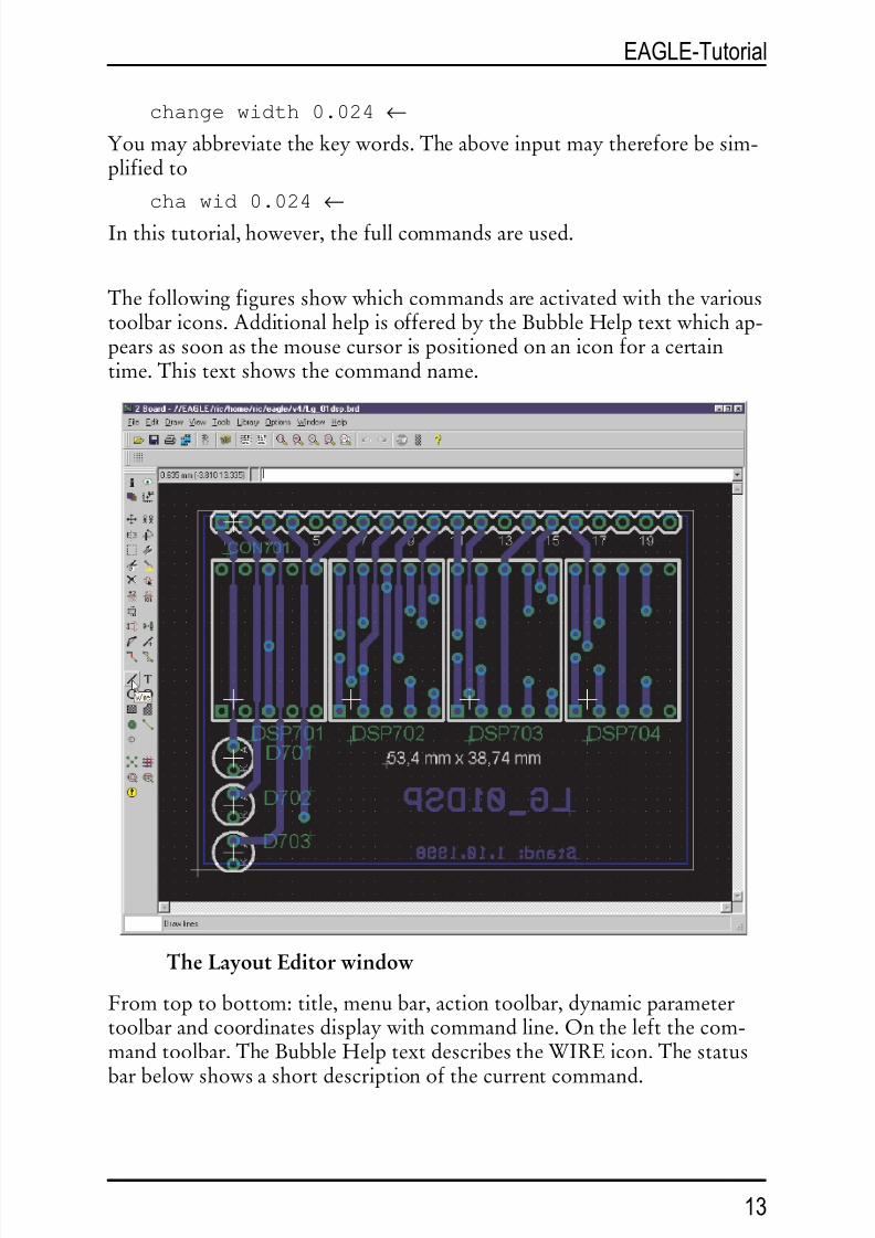
Thefollowingfiguresshowwhichcommandsareactivatedwiththevarioustoolbaricons.AdditionalhelpisofferedbytheBubbleHelptextwhichap-pearsassoonasthemousecursorispositionedonaniconforacertaintime.Thistextshowsthecommandname.
TheLayoutEditorwindow
Fromtoptobottom:title,menubar,actiontoolbar,dynamicparametertoolbarandcoordinatesdisplaywithcommandline.Ontheleftthecom-mandtoolbar.TheBubbleHelptextdescribestheWIREicon.Thestatus
barbelowshowsashortdescriptionofthecurrentcommand.
13
EAGLE-Tutorial

8/6/2019 Tutorial Eng
http://slidepdf.com/reader/full/tutorial-eng 14/5714
EAGLE-Tutorial
Info
Display
Move
Mirror
Group
Cut
Delete
Name
Smash
Pinswap
Split
Wire
Circle
Rectangle
Bus
Junction
ERC
Show
Mark
Copy
Rotate
ChangePaste
Add
Value
Gateswap
Invoke
Text
Arc
Polygon
Net
Label
Info
Display
Move
Mirror
Group
Cut
Delete
NameSmash
Pinswap
Split
Route
Wire
Circle
Rectangle
Via
Hole
Ratsnest
ERC
Errors
Show
Mark
Mirror
Rotate
Change
Paste
Add
Value
Replace
Optimize
Ripup
Text
Arc
Polygon
Signal
Auto
DRC
CommandtoolbaroftheSchematicEditor(left)andtheLayoutEdi-tor(right)

8/6/2019 Tutorial Eng
http://slidepdf.com/reader/full/tutorial-eng 15/57
8 ControlPanel
AfterstartingEAGLE,theControlPanelwillbeopened.Itallowsyoutoloadandsaveprojectsaswellastosetupcertainprogramparameters.Right
mouseclicktoanentryinthe Projects branchofthetreeviewopensacon-textmenuthatallowstostartanewproject.
ThetreeviewallowsaquicksurveyofEAGLE'slibraries.Double-clickanentryinthe Libraries branch.Nowthecontentsofthelibraryisdisplayed.Selectinganobjectshowsashortdescriptivetextontheright.
ControlPanel:Previewofthelibrarycontents
HereyougetanoverviewofUserLanguageprograms,Scriptfiles,andCAMjobs.Tryselectingvariousentries.Ontherightyouwillgetthere-ferringdescription.
TheControlPanelsupportsDrag&Drop.Arightmouseclickonanyentryinthetreeviewopensacontextmenuthatoffersoptionslikeprint,open,copy,etc.
15
EAGLE-Tutorial

8/6/2019 Tutorial Eng
http://slidepdf.com/reader/full/tutorial-eng 16/57
EAGLEFiles
ThefollowingtableliststhemostimportantfiletypesthatcanbeeditedwithEAGLE:
Type Window NameBoard LayoutEditor *.brd
Schematic SchematicEditor *.sch
Library LibraryEditor *.lbr
ScriptFile TextEditor *.scr
UserLanguageProgram TextEditor *.ulp
Anytextfile TextEditor *.*
TheLinuxversiononlyrecognizeslowercaseletterfileextensions!
EAGLEProjects
Letscreateanewprojectfirst.Afterstartingtheprogram,first • the+characterofthe Projects path,thenthe+characteroftheentries examplesand tutorial inthetreeview.Thecontentsofthe tutorial directoryappears.• tutorial withtherightmousebutton.Selecttheoption NewProject inthe
popupmenu.Namethenewproject MyProject,forexample.Thiswayyouarecreatingasubdirectoryof tutorial thatisnamed MyPro- ject.Thisdirectorywillcontainalldatafilesthatbelongtoyourproject.Of courseyoumaydefineadditionalsubdirectories.
Todefinethepathwhereyourprojectdirectorieswillbestored,click⇒Options/Directories andenteritinthe Projects field.
Arightmouseclickontheprojectentryandyoucanopennewschematics,layoutsandlibraries.Eachprojectdirectorycontainsafilenamed eagle.epf
whichstoresproject-specificsettings,windowpositionsetc.Thecurrentlyactiveprojectischecked(green)intheControlPanel.Afterstartingtheprogramagaintheprevioussituationwillberestored.Thelastusedprojectandotheruser-specificsettingsaresavedinthefile ~ /.eaglerc(Linux)or eaglerc.usr (Windows).
Beforestartingthefollowingexampleswewanttocopythefiles demo1.sch,demo2.sch,and demo2.brd intothedirectory MyProject.PresstheCtrlkey,clickthedesiredfileanddragittothe tutorial entry.Re-
leasethemousebuttonnow.Repeatthisfortheotherfiles.Nowopentheschematicfile demo1.sch withadoubleclick.
16
EAGLE-Tutorial

8/6/2019 Tutorial Eng
http://slidepdf.com/reader/full/tutorial-eng 17/57
Ifyouendtheprogramwith Alt+X andstartitagain,youwillgetthepre-vioussettingsandeditorwindows.
9 LoadFileandSelectMonitorZoom
Nowletusstartdoingsomeexercises.StartEAGLE,andwaituntiltheControlPanelappears.Expandtheentry Projects/examples/tutorial/MyProject ofthetreeview.
Nowloadthe demo2.brd file.Youcandothiseitherby • • theentry de-mo2.brd,orbyselectingthefilefromthemenu ⇒ File/Open/Board.Theschematicwiththesamenamewillbeloadedalongwiththeboard.
Enlargetheboardeditorwindow.
Nowclicktheicon tozoomintothedrawing.
Byclicking thedrawingwillbeshowninfullsizetofityourscreen.
Aclickon willzoomout.
Thecommandcontrolledbythe iconismoreversatilethaninotherprograms.Clickit,andthenmarkarectangularareabydraggingthemouse
cursorwhiletheleftmousebuttonispressed.Thenreleasethemousebut-ton,justasyouareusedtofromotherprograms.Themarkedareawillnow bedisplayed.
Ifyouwanttoselectanewcenterwiththesamezoomfactor,simplyclickthesameicon,markthecenterwithaclickandfinallyclickonthetrafficlighticonintheactiontoolbar.
Ifyouwanttoselectanewcenterandanewzoomfactorsimultaneously,clickonthesameicon.Threemouseclickswillgiveyouthedesiredresult:
thefirstclickwilldefinethenewcenterandbothlastclickswilldefinethezoomfactor.Ifthethirdpointisfurtherawayfromthefirst,theprogramwillzoomintothedrawingandviceversa.Tryittofindouthowitworks.
Duringcertainactionsitmayhappenthatobjectsinthedrawingdisappearorgetcorrupted.InthiscaserefreshthescreenbyclickingtheRedrawicon
(alsoF2possible).
Ifyouwanttomovetheselectedwindow,presstheCtrlkeywhilemovingthemouse.
FurtherpossibilitiescanbefoundonthehelppagesoftheWINDOWcommand.Thesecanbecalledupbysimplytypinginthecommandline:
17
EAGLE-Tutorial

8/6/2019 Tutorial Eng
http://slidepdf.com/reader/full/tutorial-eng 18/57
HELPWINDOW ←
10 SelectingLayersforDisplay
EAGLE-Drawingscontainobjectsindifferentdrawinglayers.Inordertoobtainausefulresultseverallayersarecombinedfortheoutput.Forexam-ple,thecombinationofTop,Pad,andVialayersisusedtogenerateafilmforetchingthecomponentsideoftheprinted-circuitboard.ConsequentlythecombinationofBottom,Pad,andVialayersisusedtogeneratethefilmforthesoldersideoftheboard.ThePadlayercontainsthethrough-holesforthecomponentconnectionsandthevialayercontainsthevia-holeswhichareneededwhenasignaltrackchangestoanotherlayer.
Loadtheboard demo2.brd usingthemenu File/Open/Board andclickinthecommandtoolbarontheiconfortheDISPLAYcommand(lookatthetoolbarlayoutonthepreviouspages).Themarkedlayersarecurrentlydis-played.Byclickingonthelayernumberthedisplayofeachlayercanbeswitchedonoroff.The All and None buttonsswitchonoroffalllayers.
Byselecting/deselectinglayer21 tPlace (silkscreenupperside),thelayers23 tOrigins,25 tNames,27 tValues,and51 tDocu areselected/deselected,too.Thesameappliestolayer22 bPlace (silkscreenbottomside).
Veryimportant: Componentsonlayer1 Top canonlybemovedorse-
lectedinthedrawingiflayer23 tOrigins ison.Thesameappliestocompo-nentsonlayer16 Bottom andthelayer24 bOrigins.
PleaseconsultthehelppageoftheLAYERcommandforthemeaningof thedifferentEAGLElayers.
11 SettingupGridandUnit
Schematics shouldalwaysbedrawnonagridof0.1inchessincethelibrar-
iesaredefinedthisway.Thegridfor boards isdeterminedbythecomponentsusedandbythecom-plexityoftheboard.
GridandunitaresetupwiththeGRIDcommandbyclickingontheGRID
icon intheparametertoolbar.Allvaluesaregiveninthecurrentlyse-lectedunit.PleaseconsultthehelppagesoftheGRIDcommandforde-tailedinformation.
18
EAGLE-Tutorial
8/6/2019 Tutorial Eng
http://slidepdf.com/reader/full/tutorial-eng 19/57
12 Wires,Circles,Arcs,Rectangles,andText
Wires,circles,arcs,rectangles,andtextarecreatedwiththeWIRE,CIRCLE,ARC,RECTANGLEandTEXTcommands.Ononehandthese
objectsserveaspuredrawingelementsforsymbols,packages,framesetc.,andontheotherhandtheycanperformspecialfunctions,suchasthedefi-nitionofrestrictedareas.
Firstanewschematicfileistobecreated.Closealloftheeditorwindowsandselect
⇒ File/New/Schematic
fromtheControlPanel.
Anewfilewiththename untitled.sch isnowcreated.Normallyyoushould
neversaveafilewiththename untitled,butshoulduse ⇒ File/Saveas tochooseadifferentname. However,inthistutorialnofileistobesavedatall.
Nowenlargetheeditorwindow.
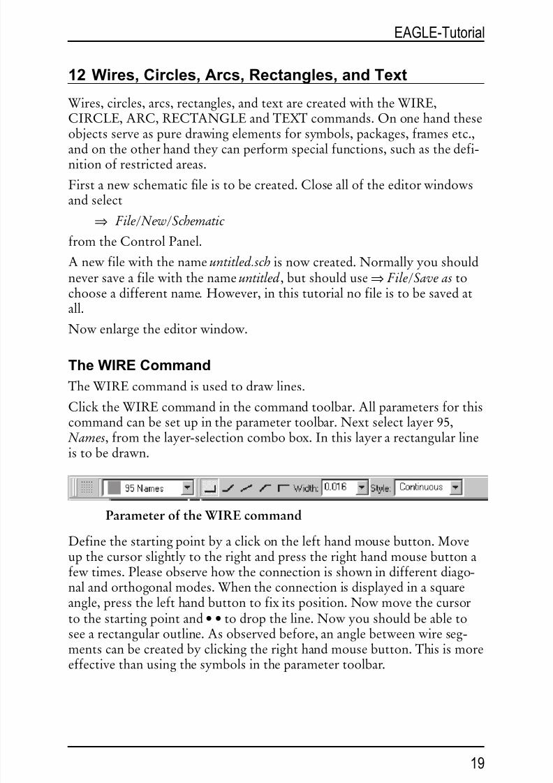
TheWIRECommand
TheWIREcommandisusedtodrawlines.
ClicktheWIREcommandinthecommandtoolbar.Allparametersforthiscommandcanbesetupintheparametertoolbar.Nextselectlayer95, Names,fromthelayer-selectioncombobox.Inthislayerarectangularlineistobedrawn.
ParameteroftheWIREcommand
Definethestartingpointbyaclickonthelefthandmousebutton.Moveupthecursorslightlytotherightandpresstherighthandmousebuttonafewtimes.Pleaseobservehowtheconnectionisshownindifferentdiago-nalandorthogonalmodes.Whentheconnectionisdisplayedinasquareangle,pressthelefthandbuttontofixitsposition.Nowmovethecursortothestartingpointand • • todroptheline.Nowyoushouldbeabletoseearectangularoutline.Asobservedbefore,ananglebetweenwireseg-mentscanbecreatedbyclickingtherighthandmousebutton.Thisismoreeffectivethanusingthesymbolsintheparametertoolbar.
19
EAGLE-Tutorial

8/6/2019 Tutorial Eng
http://slidepdf.com/reader/full/tutorial-eng 20/57
IntheLayoutEditor:
IfthelinesareplacedontheboardlayersTop,Bottom,orRoute2..15EAGLEtreatsthemaselectricallyconductingtracks.Wiresarealsousedtocreateboardoutlines.Let’sstartusingthiscommand.
ChangingLineWidth
AslongastheWIREcommandisactive,youcanselectthelinewidthfromthecomboboxintheparametertoolbarortypeinaspecificvalue,separateforeachsegment.
Tochangethelinewidthofanexistingobject,
• CHANGE iconinthecommandtoolbarandapopupmenuwillopenup.
• WIDTH iconandafurtherpopupmenuwillshowupwherethepresentvalueismarked.
Selectthedesiredvaluebyaclickofthemouse,thenclicktheobjecttobechanged.
TochangealinewidthtoavaluethatisnotshownthemenuoftheCHANGEcommand,youcanusethecommandlinetotypeinthevalue,forexample:
CHANGEWIDTH0.017 ←
andthenclickontheselectedwiresegment.
Tochangethewirestyle•
CHANGEand•
Style.Selectthestyleand•
thewireyouwanttochange.
ChangeObjecttoanotherLayer
Tomoveanobject,forexampleawiresegment,toanotherlayer
• CHANGE
• LAYER
Selectthetargetlayer,forexample94 Symbols,by•
. Then•
OK ,andthen•
ontheselectedobject(s).Notethatsomeobjects,suchasbusornetlines,cannotbemovedtoanotherlayerastheyhaveaspecialmeaning.
20
EAGLE-Tutorial
Attention:DonotusetheWIREcommandtodrawnetorbuslinesin schematics-useNETorBUSinstead!
8/6/2019 Tutorial Eng
http://slidepdf.com/reader/full/tutorial-eng 21/57
Undo/RedoFunction
OneofthemostusefulfeaturesofEAGLEistheunlimitedUndofunc-tion.Clickthelefticonasmanytimesasyouwanttoundopreviousac-tions.Usetherighticontoredotheactionswhichhavebeencancelledby
undo.
TheCIRCLECommand
ToactivateCIRCLE,whichisusedtodrawacircle,
• CIRCLE
EAGLErequirestwomouseclickstodefineacircle.Thefirstclicksetsthecenterofthecircleandthesecondclickdefinestheradius.
Placethecursoratanygridpointand • . Dragthecursorseveralgridpointstotheright.Whenthecirclehasthediameteryouwant, • tofixitandter-minatethecommand.Thelinewidthofthecirclecanbechangedasde-scribedbeforeforwires.Acirclewithlinewidth0willbefilled.
TofindoutmoreabouttheCIRCLEcommandpressF1aslongasthecommandisactivatedortype
HELPCIRCLE ←.Tocancelacommand,clickthestopsigniconoractivateanothercom-mand.PressingtheEsckeygenerallyunlocksanobjectfromthecursor.
TheARCCommand
ToactivatetheARCcommand,whichisusedfordrawingarcs,
• ARC
Anarcisdefinedwiththreemouseclicks:thefirstclickdefinesthestartpoint,thesecondthediameterandthethirdtheendpoint.
Placethecursoratthedesiredstartingpointand •.NowmovethecursorsomegridunitstotherightbutremainonthesameY-coordinate.Acircleappearswhichshowsthediameterofthearc. • andthecirclewillbecomeanarc.Nowyoucanchangethedirectionofthearcwiththerightmousebutton.Clickseveraltimeswiththerightbuttonandyouwillseewhatismeant.Youcanalsoenlargeorminimizethearcbymovingthemouse.Af-terreachingthedesiredform, • tofixthearc.
Practicebydrawingsomearcs.UsethehelpfunctiontofindoutmoreabouttheARCcommand.
21
EAGLE-Tutorial

8/6/2019 Tutorial Eng
http://slidepdf.com/reader/full/tutorial-eng 22/57
TheRECTCommand
ToactivatetheRECTcommand,usedforcreatingfilledrectangles,
• RECT
Todefinearectangletwomouseclicksarerequired:Thefirstonewillde-termineonecornerandtheseconddeterminesthepositionoftheoppositecorner.
Movethecursortothepointwhereacorneroftherectangleshouldbeand•. Movethecursorslightlytotherightandup.Whentherectanglehasreachedthedesiredsize, • tofixit.Therectangleisfilledwiththecolorof thelayerinuse.
UsethehelpfunctiontofindoutmoreabouttheRECTcommand.
TheTEXTCommand
ToactivatetheTEXTcommand,usedforplacingtext,
• TEXT
Nowtypethedesiredtextand • OK . Thenplacethetextwith •. Acopyof thesametextisnowattachedtothecursor.Tostopplacingtextsimplyclickthenextcommandicon.Forplacingadifferenttext,typethetextandterminateitwiththeEnterkey.Thetextwillshowupinthecommandline.
Textscontainingspacesorasemicolonhavetobeenclosedinsinglequotes,likethisone:
'Thisisatext'
Tochangethetextfont:
• CHANGE
• FONT
EAGLEsupportsavector,aproportional,andafixedfont.
Tochangethesizeofatext:
• CHANGE
• SIZE
• Valueinthemenu
and • lowerleftcornerofthetext.Atarotatedtextthepointoforigincanmovetoitsupperrightcorner.Atextisalwaysdisplayedsothatitcanbereadfromthefrontorfromtheright.
22
EAGLE-Tutorial

8/6/2019 Tutorial Eng
http://slidepdf.com/reader/full/tutorial-eng 23/57
Tochangeatext
• CHANGE
• TEXT
and • atthepointoforiginofthetext,theneditthetextand • on OK .Using
• CHANGE
• RATIO
youcanchangethelinewidthinatextinrelationtotheheightofthevec-torfont.
SeehelppageformoreinformationaboutTEXTandCHANGE.
SpecialTextVariables
Ifyouplacethetext
>SHEET
thisstringwillbesubstitutedwiththecurrentsheetnumber,e.g. 1/1.EAGLEoffersanumberofsimilartextvariables,e.g.fordate/timewhichreflectthelatestchangeinthefile(>LAST_DATE_TIME)orthedrawingoutput(>PLOT_DATE_TIME).Librarypartsaredefinedwithtextvari-
ablesforthename(>NAME)andthevalue(>VALUE)ofacomponent.Usetextvariablesonlyinlibraries.
13 UsingLibraries
EAGLEcomeswithalotoflibraryfilesthatcontainthrough-holeandsur-facemountdevices.ThetreeviewinEAGLE'sControlPanelandthefilelibrary.txt (in eagle/doc)offerdetailedinformationaboutthecontentsof
thelibraries.Inthissectionyouwilllearnhowtoinsertschematicsymbolsintoadraw-ingandhowtousethem.
Openanewschematictostartwithablankdrawingarea⇒ File/New/Schematic.
TheADDCommand
Toselectsymbolsfromalibrary, • ADD inthecommandtoolbar,anda
windowpopsup.Nowyoucanenteronormoresearchpatternsinthe Search field.Youmayusethenameofadeviceoranywordofthedevicedescription.Wildcards
23
EAGLE-Tutorial

8/6/2019 Tutorial Eng
http://slidepdf.com/reader/full/tutorial-eng 24/57
like*and?areallowed.
Wewanttoplace,forexample,thedevice74LS00.EnterintheSearchfield:
74*00* or 74LS00*
*isthewildcardofthetechnologyand/orthepackagevariant.Thesearchresultshowsthedeviceinvarioustechnologiesandpackagevariants.Selectthedesireddeviceand • OK .Nowyoucanplaceitintheschematic.
Placethecursorslightlytotheleftofthedisplaycenterand •. Movethecursortotheright,andplaceasecondgatewiththenextmouseclick.Placefourgatesaroundthecenterofthedrawingareainthisway.
Nowplaceafifthgatesomewherenearby.PleasenotethatEAGLEhasnamedthefirstfourgatesIC1A..IC1D,whereasthefifthgatehasbeennamedIC2A,sincethisgaterequiresasecondIC.
Ifyounowshowthelayer93, Pins,eitherasdescribedbeforeorbytyping
DISPLAYPINS ←
inthecommandline,furtherpinparametersaredisplayedingreen.Zoominonthedrawing,sothatagateisshownonalargescale.YouwillseethatthepinsaremarkedasInput(In)orOutput(Out),andthatanumbershowstheSwaplevel.ASwaplevelgreaterthan0indicatesthatthispincanbeswappedwithanotherpinofthesamedevicewhichhasthesame
Swaplevelassignment(seecommandPINSWAP).Apinwithaswaplevelof1,forexample,canbeswappedwithanyotherpinthathasaswaplevelof 1.Swaplevel0meansthatthispincannotbeswapped.
Thelayer93,Pins,isnotusuallyprinted(PRINTcommand).
AslongastheADDcommandisstillactive,agatesymbolwillbeattachedtothecursor.
NowusetheZoom-iniconortheF4keytoviewalargerportionoftheschematiconthedisplay.ThenpresstheEsckeytotheselectionwindow
oftheADDcommand.Enterthefollowingpatterninthe Search field:
555N or 555*
Selectthedevice555Nwith • •,rotateit180degreeswithtwomousebut-tonclicks,andplaceitsomewhereonthedrawingareawiththeleftmousebutton.
Repeatthiswithothersymbols.YouwillfindoutthatthelibrariescontainsymbolsdrawnintheEuropeanandtheAmericanway.Choosewhatever
youprefer. WhiletheADDcommandisactive,youcanreturntotheADDmenuby
24
EAGLE-Tutorial

8/6/2019 Tutorial Eng
http://slidepdf.com/reader/full/tutorial-eng 25/57
pressingtheEsckey.PresstheEsckeyagainandthecommandwillbecancelled.
AnotherwaytoplacedevicesintheschematicistodragthemfromthetreeviewintheControlPanelintotheSchematicEditorwindow.Arrangethe
windowsinawaythatyoucanseebothonthescreen.Select,forexample,thedevice555Nfrom linear.lbr inthetreeview( Libraries branch).UseDrag&DroptomovethedeviceintotheSchematicEditor.Ifyouselectadevicethatsupportsmorethanonepackageortechnologyvariant,youwillbeaskedtoselectthevariantinamenubeforedroppingit.
EAGLE,bydefault,assumesthatallactivecomponentswillbeattachedtothe samepowersourceandground.Thepowerpinsarethereforenotshown,and areautomaticallyconnectedtothePowerSourceandGroundwhengenerating aboard(unlesstheuserconnectsthemtoothersignals).
MostoftheEAGLElibrarydevices,whichhaveonlyoneVCCandoneGND pin,aredefinedsothatthepowerpins,bydefault,arenotvisible.InsomecasesitmakessensetomakethepowerpinsinanICvisible,asinthe555 storedinthelinearlibrary.Insuchacaseconnectthepowerpinswiththeap- propriatenets.
ThehelpfunctioninEAGLEoffersinformationaboutfurtheroptionsof thecommandsADDandUPDATEconcerningtheupdateoflibraryob-jectsinschematicandlayoutwiththeirrespectivepartsofthecurrent
libraries.
TheUSECommand
ThedefaultsettingcausestheADDcommandtosearchinalllibrariesthatareavailableinthegivenlibrariesdirectories(⇒ Options/Directories/Li- braries intheControlPanel).YoucanexcludelibrariesfromthesearchfunctionbyclickingthegreenmarkerintheControlPanel'streeview, Libraries branch.Greenmeansinuse,graynotused.
ThisisexactlythefunctionoftheUSEcommandyoucanalsotypeonthecommandline.Thesyntaxisdescribedinthehelpfunction.
TheINVOKECommand
TheINVOKEcommandcanbeusedtoallowtheconnectionofactivecomponentstoapowersourceotherthanVCCandGND.Todemon-strateitsuse
• INVOKE
• thegate IC2A
Apopupmenuappears.
25
EAGLE-Tutorial

8/6/2019 Tutorial Eng
http://slidepdf.com/reader/full/tutorial-eng 26/57
• • PWRN andthepowerpinsforIC2areattachedtothecursor.Youcannowplacethemanywherewitha • andconnectthemtoanynet.
AnotherfeatureoftheINVOKEcommandallowsyoutoalterthese-quenceofthereferencedesignatorsbeforeEAGLEautomaticallymakesan
assignment.AssumingtheINVOKEcommandisstillactive, • IC2A, andthepopupmenuappears.TheasteriskassignedtogateAindicatesthatthegatehasbeenused;thosewithoutanasteriskareavailableforuse.
IfyouwantIC2CtobeplacedbeforeIC2B, • • C inthepopupmenu.Themenucloses,andIC2Cisattachedtothecursortobeplacedwitha •.OnceIC2Cisplaced,EAGLEwilluseuptheremaininggatesinthatpack-agebeforeassigninganadditionalpackage.
Ifyouwanttoplacegatesovermorethanonesheet,usetheINVOKE
commandonthenewsheetandtypeintheelement'snameinthecom-mandline.Nowtheinvokemenupopsup.
Don’thesitatetoexperimentwithdifferentlibrariesandwithplacingandrotatingschematicsymbols.
Youcanplacedevicesinadrawingfromasmanylibrariesasyouwant.De- vicesaresavedintheschematicorboardfilesintheirentirety. Whenpassing onafile,thereisnoneedtosupplythelibrarieswiththem.
14 DrawingaSchematic
Inthissectionyouwilllearnhownetsandbusesareusedinadrawing.Youwillthenbeabletocreateaschematic.
Tocreateanemptyschematic,openanewdrawingandenlargetheeditorwindow.
Grid
Thestandardgridforschematicsis0.1inches.Symbolsshouldbeplacedonthis gridoramultipleofit,sinceotherwiseitcanhappenthatnetscannotbecon-nectedtothepins.
AddingaFrametoaSchematic
Asastart,selectadrawingframefromthelibrary frames.lbr, whichcon-tainspredefinedframesinmiscellaneousformats.
• ADD,andentertheword letter or frame inthe search field.Selectasuitable
frameand • • forexample LETTER_P. Aframewhichfitsonaletterfor-matpage(portrait)isnowattachedtothecursor.
26
EAGLE-Tutorial

8/6/2019 Tutorial Eng
http://slidepdf.com/reader/full/tutorial-eng 27/57
Ifyoucannotseeitcompletely,pressfunctionkeyF4untilitmatchesyourscreen,thenplaceitwithaclickofthelefthandmousebuttonsothatitslowerleftcornerisplacedonthecoordinates(X=0,Y=0).
Nowafurtherframeisattachedtothecursor.Clicktheiconwiththestop
signtoterminatetheADDcommand.Press:Alt+F2
toshowtheframeinfullsizeorclicktheZoom-to-fiticonintheactiontoolbar.
AddingandChangingText
Youcanaddlines,textandotherobjectstopredefinedframesandtextfieldsinthelibrary.Oryoucandesignandsaveyourownframes.
Variabletexts,e.g.theprojecttitleortherevisionnumber,canbeinserteddirectlyintheSchematicEditorwhereyouarenow.
Framesaresavedassymbolsinthelibrary,thereforeitmakessensetowritethetextinlayer94 Symbols.
Nowbringtheframetextfieldintotheeditorwindowsothatitiscom-pletelyvisible.NextclicktheiconfortheTEXTcommandandenterthefollowingtext
CadSoftAfterclickingtheOKbutton,thetextisattachedtothecursorandcanbeplacedwiththeleftmousebutton.Movethetextintheupperemptylineofthetextfieldandplaceitwitha •. Afurthercopyofthetext,whichwilldisappearassoonasanothercommandisactivatedorthestopsigniconisclicked,isstillattachedtothecursor.
IfyoudidnotdefinethesizeofthetextwhiletheTEXTcommandwasac-tive,youcanusetheCHANGEcommandtosetittoanothervalue:
•CHANGE
Fromthemenuselect:
• SIZE
andafurtherwindowopensinwhichthepresentlyselectedtextheightisshown.
• 0.15
andmovethecursortothelowerleftcornerofthetext CadSoft.Clicktheleftmousebuttonandthetextheightwillbechangedto0.15inches. JustincaseyouwouldliketosetasizenotpresentintheCHANGESIZEmenu,like.0.17,simplytype:
27
EAGLE-Tutorial

8/6/2019 Tutorial Eng
http://slidepdf.com/reader/full/tutorial-eng 28/57

8/6/2019 Tutorial Eng
http://slidepdf.com/reader/full/tutorial-eng 29/57
Schematic demo1.sch
29
EAGLE-Tutorial
8/6/2019 Tutorial Eng
http://slidepdf.com/reader/full/tutorial-eng 30/57
OnceyouhaveplacedthepartsyoucanrelocatethemwiththeMOVEcommand.ActivatetheMOVEcommandbyclickingtheappropriateiconinthecommandtoolbar,thenmovethecursortothepartyouwanttomoveand • . EAGLEwillhighlightthepart,toletyouknowthatitisat-
tachedtothecursorandreadytoberelocated.Relocatethepart,and • toplaceitinitsnewlocation.TheMOVEcom-mandisstillactiveandreadytomovethenextpart.Presstherightmousebuttonifyouwanttorotateapart.
Whenyouhavelocatedtheparts,startconnectingthemusingtheNETcommand.
TheNETCommand
Anetisonlyconnectedtoapinifitisplacedontheconnectionpointof thepin.Displaythelayer93, Pins,withtheDISPLAYcommandtolocatetheseconnectionpoints.Theyaremarkedwithagreencircle.
EAGLEautomaticallynameselectricalconnections(nets).Inourexampledemo1.sch thenetlinesatC5pin+,U1pin3(VI),andJP2pin2havethe
samename.Thepinsareconnectedtothesamenet,althoughthenetlinesarenotdrawcontinuously.
Asmentionedbefore,netswiththesamenamedefineanelectricalconnection.
TheNAMECommand
EAGLEautomaticallyallocatesnamessuchasB$..forbuses,P$..forpinsandN$..fornets.
• NAME andthen • thenetconnectedtoIC1pinOSC1(16).Apopup
menushowsthepredefinednameofthenet.TypeinOSC1
and • OK .Thenetimmediatelynowhasthisname.
Thenamesofcomponentsandbussescanbechangedinthesameway.
TheLABELCommand
TheLABELcommandallowsyoutoplacebusornetnamesonaschematic
inanylocation.• LABEL,locatethecursoronthenetMCLR/PGMand • .
30
EAGLE-Tutorial
Attention:DonotusetheWIREcommand!
8/6/2019 Tutorial Eng
http://slidepdf.com/reader/full/tutorial-eng 31/57
Thenameofthenetisattachedtothecursorandyoucanplaceitinanylo-cation.Youcanalsorotatethelabelwiththerightmousebutton.Locatethelabelapproximatelyasshowninthefigureand • tofixitsposition(nearJP1pin2).
Ifnetorbusnamesarechanged,therelevantlabelsarealsochanged.LabeltextisnotchangedwiththeCHANGETEXTcommandbutwiththeNAMEcommand.
CHANGEFONTorCHANGESIZEchangesthefontorthetextsize.
TheDELETECommand
Youcandeleteobjectswiththiscommand.Ifitisappliedtonets,wiresorbusses,asinglesegmentisdeletedatatime.Tousethiscommand,•
DELETE inthecommandtoolbar,takethecursortotheobjectthatistobedeleted,and •.
UNDOandREDOworkhereaswell.GROUP,DELETEandarightmouseclickdeletewholegroups.
TheJUNCTIONCommand
Droppinganetonanothernetlinegeneratesaconnectionbetweenthesetwonets.Theconnectionwillberepresentedbyajunction,thatwillbeset
automatically.Automaticsettingofjunctionscanbeswitchedoffwiththeoption Autosetjunctions (⇒ Options/Set/Misc).
InthiscasetheJUNCTIONcommandisusedtodrawaconnectingnodeattheintersectionofnetswhicharetobeconnectedtoeachother.
• JUNCTION andanodeisattachedtothecursor.Locatethenodeatthejunctionoftwonetlinesand • tofixitintoplace.
TheSHOWCommand
ThisisagoodtimetodemonstratethefunctionoftheSHOWcommand.Thiscommandisusedtoshownamesandotherdetailsofelementsandob-jects.Completesignalsandnetscanbehighlighted,aswellascomponents.
ToshowforexamplethenetV+, • SHOW inthecommandtoolbarthenmovethecursortotheconnectionpointofU1pinVI(3)and •.
PleasenoticethatEAGLEhighlightsthenetwiresandeachpinconnectedbythisnet,aswellasthepinnameofeachparttowhichitisconnected.Inaddition,thesignalislistedas
Net:V+
inthestatusbar.
31
EAGLE-Tutorial

8/6/2019 Tutorial Eng
http://slidepdf.com/reader/full/tutorial-eng 32/57
WhiletheSHOWcommandisactivethenetremainshighlightedalthoughyouarepanningthewindowbypressingtheCtrlkeyandmovingthemouseorusingtheWINDOWcommand.DeactivatetheSHOWcom-mandbyclickingthestopsigniconanduseWINDOWREFRESH(F2).
Nowtheobjectsarenolongerhighlighted.Toshowanobjectwithaspecificname, • SHOW andtypethename(forexample D0 ←)inthecommandline.YoucansubsequentlytypeothernameswithouttheneedtoreactivatetheSHOWcommand.Thiswayyoucanmarkonenetaftertheother.
Doyouwishtohighlightseveralnetsatthesametime,enterinthecom-mandline:
SHOWRA4 ←
SHOWRA3 ←
SHOWRA2 ←
TheMOVECommand
Inordertoavoidmistakeswhenplacingandmovingnetsyouhavetoun-derstandthefollowingeffectsoftheMOVEcommand:
Noelectricalconnectionwillbegeneratedifyoumoveanetlineoverapin(usingtheMOVEcommand).Ontheotherhand:ifyoumoveapinoveran-otherpinoroveranetline,anelectricalconnectionwillbegenerated,andanetlinewillbeattachedtothepinwhenthecomponentismovedfurther.Re-membertheUNDOcommandifyouwanttodetachthenetline.
ChecktheconnectionswiththeSHOWcommand,asmentionedbefore.AdditionalonecanexportanetorpinlistwiththeEXPORTcommand.
HistoryFunction
Withthekeys up-arrow and down-arrow youcanrecallthelastkeyboardinstructionintothecommandlineandexecuteitwiththeEnterkey.TheEsckeywilldeletethecommandline.
UseAlt+F2toshowthewholeschematiconthescreen,thentype:
SHOWR1 ←
SHOWC1 ←
SHOWIC1 ←
QuittheSHOWcommandbyclickingthestopsignicon. Redrawthe
screen,e.g.withF2andpressthe up-arrow and down-arrow keysseveraltimes.Asyoucansee,youcanscrollthroughthelistoftherecentlyusedcommands.Assoonasthedesiredcommandappearsinthecommandline
32
EAGLE-Tutorial

8/6/2019 Tutorial Eng
http://slidepdf.com/reader/full/tutorial-eng 33/57
presstheEnterkey.
CompletingtheSchematic
UsetheADDcommandtoaddtheremainingcomponentsandthesym-bolsforVCC,V+,andGNDfrom supply.lbr (searchpattern: supply).SupplysymbolsrepresentthepowersignalsinyourschematicandcausetheERC(ElectricalRuleCheck)tousespecialchecksforthem.
RememberthatyoucanusetheMOVEcommandtomoveobjectsaroundandthatyoucanrotateelementsattachedtothemousewitharightmouseclick.
UsingtheNETcommand,connectthepinsofthecomponentsaccordingtotheschematicandconnectthesupplysymbolstotherelatedpins.Use
therightmousebuttontoalternatebetweentheorthogonalanddiagonalmodeswhileusingtheNETcommand.Use • tofixasegment.
Ifyouplaceanetexactlyonaconnectionpoint,thenetisterminatedatthislocation.
TheSMASHCommand
Youwillnoticethatwhenyourotatediodesandresistorsfromthehori-zontaltotheverticalposition,theirreferencedesignatorsandvaluetexts
rotatewiththepart.EAGLEprovidesaSMASHcommandthatallowsyoutoMOVEandROTATEthenameandvaluetextsindependentlyofthesymbol.
Toactivatethecommand
• SMASH
Locatethecursoronthediodesymboland •. Thisseparatesthetextfromthesymbol.Nowclickthe MOVE icon,movethecursortothename D1 forthediode,and •.
Thetextselectionpointismarkedasacrossandresides,dependingontherotation,onthelowerleftortheupperrightcorner.
Thenameisnowattachedtothecursor.Itcanbemovedtoabetterloca-tionandrotatedwiththerightmousebutton.WhenyouhaverotatedandrelocatedD1, • tofixitslocation.
IfyouwanttochangethesizeofnameandvaluetextswhichhavebeenseparatedfromthepartwiththeSMASHcommand,usetheCHANGESIZEcommand(clicktheCHANGEiconandselect Size fromthemenu).
33
EAGLE-Tutorial

8/6/2019 Tutorial Eng
http://slidepdf.com/reader/full/tutorial-eng 34/57
TheVALUECommand
EAGLEallowsyoutodefineortochangethevalueelementslikeresistorsorcapacitors.InthecaseofICsthevalueinformsyouabouttheelementtype(e.g.74LS00N).
• VALUE
• theresistor,
typethenewvalue, 2.2k, • OK ,andthenewvalueisnowdisplayed.
YoucanusetheNAMEcommandtochangethenamesofresistors,capaci-tors,ICs,netsandbusesaccordingly.Youcanchangethenetnamesbutyoudon’thaveto,unlessyouwanttogetadescriptivenetlist.
TheElectricalRuleCheck(ERC)Ifyouhaven’tenteredthecompleteschematicyourselfyoucannowloadthefile demo1.sch.
TheERCcommandisusedtotestschematicsforelectricalerrors.
Theresultsarewarningsanderrormessagesthataregeneratedandwrittenintoafilewhichhasthesamefilenameasthedrawingbuttheextension*.erc.Thisfileisautomaticallydisplayedinatexteditorwindowifmes-sagesweregenerated.TousethecommandclicktheERCiconinthecom-
mandtoolbar.Pleasenotethat theERCcanonlydiscoverpossibleerrorsources.Itisupto youtoproperlyinterprettheERCmessages!
IfyouwanttolearnmoreabouttheERCcommand,type
HELPERC ←
inthecommandline.
GeneratingaBoardfromaSchematicAfterloadingaschematicfromwhichyouwouldliketodesignaboard,clickontheBOARDiconintheactiontoolbar:
Aboardfilewillbegeneratedinwhichthepackagesarepositionednexttoanemptyboard.
Afurtherdescriptionfollowsinthechapter DesigningaPCBoard.
Butnowwewanttointroduceanotherimportantcommandthatisneces-sarytodesignschematicsfirst.
34
EAGLE-Tutorial
8/6/2019 Tutorial Eng
http://slidepdf.com/reader/full/tutorial-eng 35/57
TheBUSCommand
Loadtheschematic bus.sch fromthe /eagle/examples/tutorial directory.
Aschematicwithabusstructureappears.Abushastobedrawnwiththe
BUScommand.Itisnamedautomatically(B$1..).Abushasnologicalsignificance.Itisadrawingelementonly.Logicalcon-nections(nets)areonlydefinedwiththeNETcommand.Netswiththesamenameareidenticaleveniftheyareondifferentpagesofaschematicoropticallynotconnected.
Thebusnamedeterminesthesignalscontainedinthebus.InourexamplethebuscontainsthesignalsVALVE0toVALVE11andasignalnamedEN.Thereforethebushasbeennamed EN,VALVE[0..11] withtheNAMEcommand.
Thebusinourexamplehasnotbeenfinished,yet.Therearestillsomecon-nectionstodraw.StarttoconnectthefollowingsignalstoIC7byselectingtheNETcommandandclickingonthebusline:
ENIC7Pin14ENVALVE0IC7Pin16INAVALVE1IC7Pin15INBVALVE2IC7Pin10INCVALVE3IC7Pin9IND
•NET inthecommandotoolbarandmovethecursoroverthebus,onegridlineoverthepinIC7-14.Thenetconnectiontothebusmustoriginate
fromthebusandbedrawntothecomponentpin,ifyouwanttousethisconvenientwaytonameit. • tosetthestartingpointofthenet,andapopupmenuwillappearwiththenetnamesforthebus. • EN toselectnetEN,andmovethecursortoIC7-14,usingtherightmousebuttontochangethelineuntilitisdrawnliketheothernetlinesinthisarea. • thepin'sconnectionpointtofinishthenetline.
RepeatthisactionforVALVE0..VALVE3.
UsetheLABELcommandtomakethenetnamesvisibleintheschematic.
Ifyouwanttocancelanaction,clicktheUNDOicon,orusetheF9key.EitherbyclickingontheREDOiconorbyuseoftheF10keyyoucanper-formthecancelledactiononceagain.
UsetheMOVEcommandtomoveindividualbussegments.Selectaseg-mentneartotheendinordertomovetheendpoint.Selectasegmentsomewhereinthemiddle,tomoveittoaparallellocation.YoucandeleteindividualsegmentswithDELETE.
Thecursortakesontheformoffourarrowswhenyouwanttoselectanobject whoseoriginisveryclosetotheoriginofanotherobject.Inthissortofcase,
35
EAGLE-Tutorial

8/6/2019 Tutorial Eng
http://slidepdf.com/reader/full/tutorial-eng 36/57

8/6/2019 Tutorial Eng
http://slidepdf.com/reader/full/tutorial-eng 37/57
promptsyoutousetheSchematicEditor.
TomonitortheForward&BackAnnotationloadthe demo2.sch file.Theboard demo2.brd willbeloadedautomaticallyintotheLayoutEditor.
Nowsizebothofthewindowssothatyoucanseethembothonthescreen.ChangesomenamesandvalueswiththeNAMEandVALUEcom-mands.Youwillnoticethatthenamesandvalueschangeinbothwindows.ExperimentalsowiththeDELETEcommandandremembertheUNDOandREDOcommands.
17 DesigningaPCBoard
InthissectionyouwillcreateasmallPCBdesignandmodifyanexisting
designusingtheLayoutEditor.First,youwillcreateaboardwithoutaschematic.ThissectionisusefulmainlyforthoseuserswhohavenoSche-maticModule.IfyouhavetheSchematicModuleyouwouldnormallynothavetodealwiththestepsdescribedinthefollowingsection.Youshould,however,readthroughthissectionasitdealswithsomegenerallyusefulpoints.
DesigningaBoardwithoutaSchematic
Openanewfile(⇒
File/New/Board intheControlPanel)andenlargetheeditorwindow.
DefiningBoardShape
Thefirstthingwewilldoisdefinetheshapeoftheboard.Beforedefiningtheshape,wemustestablishtheunitofmeasurementwewillbeusingtodrawtheboardoutline.Wewanttousethedefaultgridwhichcanbecho-senbyclickingtheGRIDiconintheparametertoolbar.Then • the Defaultbuttonand • OK .
TheboardoutlinesmustbedrawnwiththeWIREcommandinlayer20, Dimension: • WIRE,andselectlayer20fromthecomboboxintheparame-tertoolbar.
Positionthecursoratthezeropointofthecoordinates,and • todeterminethestartingpointoftheoutline.Movethecursorslightlytotheright,clicktherightmousebuttonuntilbothlinesareorthogonal(90degrees),andpositionthecursornearthecoordinates (4.003.00).
Fixtheoutlineatthispointwith • andmovethecursorbacktothecoordi-nates’zeropoint.
Bydouble-clickingtheleftmousebuttonyouwillterminatetheWIRE
37
EAGLE-Tutorial

8/6/2019 Tutorial Eng
http://slidepdf.com/reader/full/tutorial-eng 38/57
command.Theboardoutlinesarenowdefined.
UsingtheMOVEcommand,theedgescanbemoved,oruseUNDOandREDOtorecallthepreviousactionsandperhapsmakechanges.
Alt+F2, orclickingtheZoom-to-fiticon,willfittheboardintothescreen.
PlacementGrid
Beforeplacingcomponents,itisimportanttosetupthegridforcompo-nentplacement.Thecomponentplacementgridmaybedifferentfromthegridusedfordrawingtheboardshape,andisalmostalwaysdifferentfromthegridusedforroutinginterconnectwires.Forthefollowingexercisewewillusethedefaultgridof0.05,incheswhichisalreadyset.
PlacingComponents
• ADD inthecommandtoolbarandsearchfor DIL14.
Double-clickona14-pinDILpackageentry.Nowitisattachedtothecur-sor.Itcanberotatedwiththerightmousebuttonandthenplacedwiththeleftmousebutton.PlacetwoDIL14packages.
UsetheF3andF4keytozoominandout.
Ifyouliketouseanotherpackagethanthepredefinedone(e.g.asmdin-
steadofathrough-holepackage),youcanusetheREPLACEcommand.Fordetailedinformationspleasetakealookintothehelpfunction.
PlacingSMDPackages
NowuseADDtoplacetwo1210packagesontheboard(searchpattern: R1210).Ifyouknowthepackagename,youcantype
ADDR1210 ←
or
ADDR1210@smd-ipc
inthecommandlinetofetchthepackagefromacertainlibrary.
TheSMDpadsappearinred,whichmeans,thattheyareonthelayer1,Top,oftheboard.TotransferthemtotheBottomlayerusetheMIRROR command.ClickontheMIRRORiconinthecommandtoolbarand • onthepackage.
AslongastheMIRRORcommandisactive,youcanmovepackagestotheothersideoftheboard.Forthenextexercisethepackagesshouldbeplaced
ontheToplayer(red).
38
EAGLE-Tutorial

8/6/2019 Tutorial Eng
http://slidepdf.com/reader/full/tutorial-eng 39/57
ProvidingNames
Toassignanametothepackagesjustplaced:
• NAME inthecommandtoolbar.
Movethecursorneartheoriginpoint(markedwithacross)ofthefirstDIL14and • . Apopupwindowappears.Type
IC1 ←
andthenewnameisassignedtothepackage.RepeatthisprocesstonametheremainingpackagesIC2,R1,andR2.
ProvidingValues
Toassignvaluestoanelement:
• VALUE inthecommandtoolbar.
MovethecursorneartheoriginofIC1and• .
Apopupwindowappears.Type
CD4001 ←
andIC1nowhasthevalue CD4001.UsingtheVALUEcommandassignCD4002 toIC2, 100k toR1,and 22k toR2.
DefiningSignals
Thenextstepistodefinesignalsandestablishtheirconnectionsusingair-wires(rubberbands).First,connectthegroundpads:
• SIGNAL andtype
GND ←
• onpad7ofIC1(IC1-7)andmovethecursortoIC2-7and • • totermi-natetheGNDairwire.
ThetwopadsarenowconnectedtotheGNDsignal.NextwewillconnectVCC.Type
VCC ←
• onIC1-14,movethecursortoIC2-14and • • toterminatetheVCCairwire.
Definefurthersignalsusingthesameprocedure.
Ifyoudon’twanttospecifynamesforthesignalsatthistime • apadto
startasignaland • • apadtoterminateit(orclickthestopsignicon).EAGLEwillthengeneratenetnamesautomaticallywhichcanbechangedwiththeNAMEcommand.
39
EAGLE-Tutorial

8/6/2019 Tutorial Eng
http://slidepdf.com/reader/full/tutorial-eng 40/57
EAGLEterminology: Padsarethrough-holesforconventionalcomponents(usedinpackages).Pinsareconnectionpointsforschematicsymbols.Smd’s arethepadsofsurfacemounteddevices(usedinpackages).
AirwirescanbedeletedwiththeDELETEcommandifyoudon’tworkun-
derForward&BackAnnotationcontrol(insuchacaseyouhavetodeleteasignalbydeletingtherelatednetsintheschematic).
PleasenotethatUNDOandREDOfunctionunderthecontroloftheForward&BackAnnotation,too.
DefiningSignalClasses
TheCLASScommandallowsyoutodefinesignalclassesandtoassigncer-tainvaluesconcerningwirewidthandminimumdistancetoothersignals,
andminimumdrilldiameterforviastoeachclass.Forexample,powersupplysignalsmayberoutedwithahigherwirewidth(highercurrent)orahighervalueforclearance(highervoltage).Thevalueforwirewidthwillbepresetifyoustartroutingthissignalinthelayout.Theautorouterusesthesevaluesforrouting,too.
Thedefaultvalueis0forallattributes(noclassesdefined).ThismeansthevaluessetintheDesignRulesarevalidforallsignals.
Variousclassesareusedintheboardfile hexapodu.brd.
CreatingaBoardfromaSchematic
IfyouhavetheSchematicModuleandtheschematicisalreadydrawn,youonlyneedafewstepstogetthesameresultasthatdescribedintheprevi-oussection.
GeneratingaBoardFile
Loadthefile demo1.sch andclickontheBOARDicon:
Withthiscommandyoucreateaboardfilewiththesamenameastheloadedschematic(demo1.brd).Answerthe Createfile? questionwith • OK .MaximizetheLayoutEditorwindow.
Thewhiteframeontherightofthewindowsymbolizestheboardoutlines.Itismadeupofwiresinthelayer20, Dimension.
•
MOVE,and•
therightverticaledgeoftheboardshapesomewhereinthemiddle.Movethecursoralittletotheleftand • .
Youhavenowreducedthesizeoftheboard.Youcanchangetheboardsize
40
EAGLE-Tutorial
8/6/2019 Tutorial Eng
http://slidepdf.com/reader/full/tutorial-eng 41/57

8/6/2019 Tutorial Eng
http://slidepdf.com/reader/full/tutorial-eng 42/57
Ifyouwouldliketochangeallroutedtracksintoairwires, • theRIPUPiconandthen • thetrafficlighticon.Confirmthequestion Ripupallsig-nals? with • OK .
YoucanstarttheAutorouteratanytime,regardlessofwhetherthereare
routedtracksoronlyairwiresontheboard.Typically,supplysignalsandothercriticalsignalpathsareroutedmanually,beforetheAutorouterisused.
RoutingManually
TheROUTEcommandchangestheairwiresintoroutedtracks.
• ROUTE inthecommandtoolbar.
• startingpointofanairwire.
AsfortheWIREcommand,furtherparameters,suchaswidthortargetlayer,canbeenteredwithhelpoftheparametertoolbar.
AllvaluesrelatetothecurrentunitselectedwiththeGRIDcommand.
Movethecursortoroutethesignal, • tofixthecurrentsegment. • • tofixthelastsegmentandendtherouteoperationforthewholesignal.
SincetheROUTEcommandisstillactive,youcanimmediatelystartrout-inganewsignal.
WhiletheROUTEcommandisactiveyoucanselecttheanglebetweentwowiresegmentswiththerighthandmousebutton.
Ifyouchangethetargetlayerduringtheroutingprocessbyselectingitfromthecomboboxintheparametertoolbar,thefollowingwiresegmentswillbedrawnonthenewlayer.Thenecessaryvia-holewillbegeneratedautomaticallybyEAGLE.
BoardChanges
Onceyouhavecompletedtheroutingoftheboardyoucanmakechanges,e.g.youcan:
• moveandarrangewiresegmentsandcomponentswithMOVEandSPLIT,
• usetheRIPUPcommandtochangeroutedtrackstoairwires,
• useDELETEtoerasesignals(onlywithoutForward&Backannotation),
• replacepackagevariantswithCHANGEPACKAGEorREPLACE
(withoutschematic).In demo3.brd thepackageofIC1hasbeenreplacedbyaSMDpackage.
YoucanstarttheAutorouteranytimeyouwant,whethermanuallyrouted
42
EAGLE-Tutorial

8/6/2019 Tutorial Eng
http://slidepdf.com/reader/full/tutorial-eng 43/57
tracksexistornot.TheroutedtrackswillnotbetouchedbytheAutor-outer.Typically,thepowersignalpathsandothercriticalsignalsareroutedmanually,beforetheboardispassedontotheAutorouter.
FurtherUsageoftheLayoutEditor Inthissectionyouwillmodifyarouteddemoboard.Loadthefiledemo2.brd,andenlargetheeditorwindow.
Nextafewimportantcommandswillberepeated.
DISPLAYCommand
Itisofteneasiertomaintainagoodoverviewifsomeinformationisnotshown.
• DISPLAY
andselectwithyourmousethelayer21, tPlace.Thislayercontainsinfor-mationforthetopsidesilkscreenoftheboard.Byselectingordeselectingit,thelayers23 tOrigins,25 tNames,27 tValues,and51 tDocu willbeshownorhidden.
Toactivatethischange, • OK .
MOVECommand WiththeMOVEcommandyoucanmoveforinstancewires(linesorsignaltracks).Selectingawiresegmentnearanendpointwillmovetheendpointofthewire.Selectingthewireinthemiddlewillmoveitinparallel.
Youcanalsomovevias(through-holeswhichconnectTopandBottomlayertracks).Whenmovingvias,theattachedwiresarealsomoved.
TomovecomponentsplacedontheToplayer,layer23 tOrigins hastobedisplayed.ThesameappliestocomponentsplacedontheBottomlayerand
layer24 bOrigins.AslongastheMOVEcommandisactive,youcanrotatetheobjectwiththerightmousebutton.
GROUPCommand
OneofthemostusefulcommandsofEAGLEistheGROUPcommand.Itallowsyoutoselectseveralobjects,changetheirattributesandmove,ro-tateormirrorthemallatonce.TousetheGROUPcommand
• GROUP
Then,byclickingandreleasingtheleftmousebutton,drawapolygon
43
EAGLE-Tutorial

8/6/2019 Tutorial Eng
http://slidepdf.com/reader/full/tutorial-eng 44/57
aroundagroupofobjectsandclosethepolygonbypressingtherightmousebutton(don’tusethePOLYGONcommand).Theselectedobjectsarenowhighlighted.
Pleasemakesurethatyouonlyselectobjectswhichareinavisiblelayer.Pack-
agesonthe Toplayercanonlybeselectediflayer23 tOrigins isvisible,and packagesatthe Bottomlayercanonlybeselectediflayer24 bOrigins isvisible.UsetheDISPLAYcommandtoshoworhidelayers.
NextselecttheMOVEcommandandusethe right mousebuttontoattachthegrouptothecursor.Thiswayyoucanmovealltheobjectssimultane-ously,rotatethemwiththerightmousebuttonandfixthemwiththeleftmousebutton.
AfteragrouphasbeendefinedwiththeGROUPcommand,theattributes
ofthecontainedobjectscanbechangedwiththeCHANGEcommand.Se-lectagroupthatcontainssomewires, • CHANGE inthecommandtoolbar, •
Width,and • 0.032.Thenclickthe right mousebuttonsomewhereintheeditorwindow.YoucanreversetheactionwiththeUNDOcommand.
ArectangulargroupcanbedefinedbyselectingtheGROUPicon,clickingonecorneroftheareaofinterest,keepingthemousebuttonpressedanddraggingthemousebuttonuntiltherectanglecontainsthedesiredobjects.
SPLITCommand
WiththeSPLITcommandyouaddabendinawire.
• SPLIT inthecommandtoolbar
• onawiresegmentnearitstargetpoint
Dragthewireonthescreenabit.Youwillseethatthelongersegmentre-mainsasadirectlinetotheselectedpoint,whiletheshortersegmentsplitsintotwo.Theangleofthetwonewsegmentsiscontrolledwiththerightmousebutton. • fixesthewiresegments.
CHANGECommand
UsetheCHANGEcommand,tochangethewidthofwiresortomoveawiretoanotherlayer.Tochangethewidthofthewire:
• CHANGE
• WIDTH inthepopupmenu
• thevalueforthenewwidth
Thenmovethecursortothewiresegmenttobechangedand •.Tochangethewidthtoavaluenotpresentinthemenu,e.g.to0.23inches,type
44
EAGLE-Tutorial

8/6/2019 Tutorial Eng
http://slidepdf.com/reader/full/tutorial-eng 45/57
CHANGEWIDTH.23 ←
inthecommandlineandclickthewiresegment.
Tomoveawiresegmenttoanotherlayer:
•CHANGE
• LAYER
• desiredlayer
• wiresegment
Incaseaviaisneededtocompletethesignalpath,EAGLEwillautomati-callyinsertit.Ifaviabecomesredundant,EAGLEwillautomaticallyre-moveit.
ROUTECommand
UsetheROUTEcommandtochangeanairwireintoawire.Youcanfixthepositionofawiresegmentwith • ,thenchangedirectionandfixthenextsegment untiltheairwireiscompleted.
RIPUPCommand
IfyouwouldliketoturnforexampletheroutedsignaltracksGNDandVCCintoairwires(thisprocessiscalled ripup),clicktheRIPUPiconinthecommandtoolbarandtype:
GNDVCC ←
PressingF9twicereversestheaction.
IfyouwouldliketoripupallsignalsexceptGNDandVCC,type:
!GNDVCC ←
aftertheRIPUPcommandhasbeenactivated.
SHOWCommand
UsetheSHOWcommandtohighlightairwires,wiresorcomponents.ClickontheZoom-to-fiticonandthentheSHOWicon.Thentype:
IC1 ←
tolocateIC1.
RefreshScreen
UsetheF2keytorefreshthescreencontentsorclicktheRedrawicon.
45
EAGLE-Tutorial

8/6/2019 Tutorial Eng
http://slidepdf.com/reader/full/tutorial-eng 46/57
Undo/RedoFunction
AllactionsmentionedcanbereversedwiththeUNDOiconintheactiontoolbar(F9)andrepeatedwiththeREDOicon(F10).
InnerLayers
Innerlayers(Route2...15)canbeusedforroutinginthesamewayastheTopandBottomlayers.
Thisisnotpossibleinthefreeware(lightedition).
SupplyLayers
Onlypossibleinstandardandprofessionaledition!
Innerlayers(Route2..15)canbeusedasasignalorgroundplanesimplybyrenamingthelayer $signalname, whenallsignalswiththatnamewillthenbeconnectedtothislayer.Todemonstratethisfeatureloadtheboardfiledemo2.brd andtype:
SHOWGND ←
TheGNDsignalwillbehighlighted.
Thentype:
RIPUPGND ←
ThesignalGNDwillnowbedisplayedasairwiresonly.
Nowwewilldefinelayer2asthegroundlayerbynamingit $GND (thenameofthesignalmustbeprecededwiththe$):
LAYER2$GND ←
YoucanalsoselectLayer2 Route2 intheDISPLAYmenu,clicktheChange button,activatetheoption SupplyLayer andtypeinthenameGND.
ClicktheRATSNESTicontomaketheairwiresofthesignalGNDdisappear.
Tohavealookattheresultswitchofalllayersexceptforthe$GNDlayer.ThiscanbeachievedbyclickingontheDISPLAYicon,orsimplybytyp-ingthefollowingcommandonthecommandline:
DISPLAYNONE$GND ←
Rememberyoucanuselowercasecharactersandabbreviatekeywords.Soyoucantype
disnone$gnd ←
Nowtype
46
EAGLE-Tutorial
8/6/2019 Tutorial Eng
http://slidepdf.com/reader/full/tutorial-eng 47/57
SHOWGND ←
andthethermalsymbolswhichconnecttheGNDsignaltothesupplylayerarehighlighted.Theannulus(round)symbolsisolatethethrough-holesnotbelongingtotheGNDsignal.
InourexampletheelementsC1andC2don'thaveaconnectiontothein-nerlayeryet.YouhavetoROUTEashorttrackoutofthesmdandplaceaVIAonthetracksend.Nowtheconnectiontotheinnerlayerismade.
Supplylayersdefinedwith$nameareplottedinversely,i.e.,objectswiththecolorofthesupplylayerdefinecopper-freeareas.Thethermalsymbolsconnectthegroundplanewiththethrough-holeusingfourconductingpaths.
CopperPouring
ThePOLYGONcommandenablesyoutodefineareaswhichbelongtoasignal,connectingalloftherelatedpadstothissignalwiththermalsym-bols.Suchasignalretainsauser-defineddistancetoanyothersignalpath. Youcandesignlayersthatcontainmultiplepolygonssuchasdifferentgroundareas,andyoucandesignpolygonsonmultiplelayers.
TodemonstratethisfeatureofEAGLE,let’sfilltheToplayerofaboardwiththeGNDsignal.Reloadtheboard demo2.brd onceagain,enlargethewindow,andripuptheGNDsignal:
RIPUPGND ←
UsetheDISPLAYcommandtoswitchonthelayer1Top, 17 Pads, 18Vias, and20 Dimension.Usethebutton None, inthemenu,toswitchoff thedisplayofallotherlayersfirst.
ClickthePOLYGONiconinthecommandtoolbarandtype:
GND ←
toprovidethename GND forthepolygontobedefined.OnlythenwillitbelongtotheGNDsignal.
SelecttheLayer Top fromthecomboboxintheparametertoolbar.Then:
• lefthanduppercorneroftheboardoutlines,
• righthanduppercorner,
• righthandlowercorner,
• • lefthandlowercorner.
Thedoubleclickclosesthepolygon.
Tostartthecalculationofthefilledarea,clicktheRATSNESTicon.Sincethisisaverycomplexoperationitcantakesometime.
47
EAGLE-Tutorial

8/6/2019 Tutorial Eng
http://slidepdf.com/reader/full/tutorial-eng 48/57
Asbefore,thepadsbelongingtotheGNDsignalareconnectedwithther-malsymbols.Checkthiswith:
SHOWGND ←
Inthiscaseeverythingshowninthelayercoloriscopper,sincethislayerisnotplottedinversely(onlysupplylayersdefinedwith $name).
Afteraboardhasbeenloaded,polygonsaredisplayedwiththeiroutlines.The filledareasaredisplayedonlyaftertheRATSNESTcommandhasbeenexe-cuted.Inversely,theRIPUPcommandandasingleclickontheedgeofapoly- gonresultsintheoutlinedisplayofthisparticularpolygon.
CallupthehelpfunctiontofindoutmoreaboutthePOLYGONcom-mand.
18 Autorouter
NoAutorouteronearthwilllayyourboardoutexactlyasyouwouldlike.Butitcanfreeyouofalotofboringwork.Inthissectionwewanttodem-onstratethatyoucaneasilycombinemanualandautomatedrouting.
Loadtheboard hexapodu.brd.
Switchofflayer21 tPlace usingtheDISPLAYcommand,sothatthecom-ponentsarenotshownanymore.
ThisboardcontainsmanuallyroutedsignalsnamedAC1andAC2.Rectan-glesinthelayers41, tRestrict,and42, bRestrict,havebeenusedtocreatere-strictedareasfortheAutorouter.WithintheseareastheAutorouterisnotallowedtoroutetracksontheToporBottomlayers.ComponentB1iscoveredbyarestrictedareadrawninlayer43, vRestrict.ThismeanstheAutoroutermustnotsetviasthere.
StarttheAutorouterbyclickingtheAUTOiconinthecommandtoolbar.
Apopupmenuappearswhereyoucanenterindividualsettings(seehelp).
Youshouldchoosearoutinggridof10mil(0.254mm)for hexapodu.brd.
Youcanalsoloadtheautorouterparametersforthisfilefromthecontrolfile hexapodu.ctl byclickingthe Load.. button.
Aswewanttoroutealloftheunroutedsignals • OK .
Incaseyoudon’twanttochangethesettingsoftheAutorouteryoucanstartitbytyping:
AUTO; ←
inthecommandline.Themenuisskippedinthiscase.
Watchthestatusmessagesappearinginthestatusbar.Theyinformyou,
48
EAGLE-Tutorial

8/6/2019 Tutorial Eng
http://slidepdf.com/reader/full/tutorial-eng 49/57
forinstance,ofhowmanysignalshavebeenrouted,orofhowmanyviashavebeenplacedatthemoment.YouwillnoticethatthenumberofviasgoesdownduringtheOptimizepasses.
IfyouwanttointerrupttheAutorouterclickonthestopicon.
Aprotocoloftheroutingrunisstoredinthefile hexapodu.pro.Loaditintoatexteditorwindowtohavealookatit.
TheboardroutedbytheAutoroutercanbeeditedlikeanyotherboard.Shouldtheroutingresultbelessthan100%,youcanripupafewcriticalsignalsandroutesomeoftheremainingairwiresmanually.Ifyouwanttorestoretheoriginalstatus,turnroutedtracksintoairwires(withtheexcep-tionofAC1andAC2)withthecommand
RIPUP!AC1AC2 ←
19 DesignRuleCheck
WhenstartingthelayoutdevelopmentyoushouldalreadythinkabouttheDesignRules.Rulesthathavetobeconfirmedwiththeboardmanufac-tureraswell.YoucandefinethemwiththehelpoftheDRCdialog.ClicktheDRCiconandverifyorchangethedefaultvalues.Aclickintooneof theparameterfieldsshowsadescribingpicture. • Apply tosavetheDesign
Rulesintheboardfile. OK startstheDesignRuleCheck.The Select buttonallowsyoutoselectacertainareaofthelayouttobechecked.Simplydragarectanglewiththemousearoundthearea.
TheDRCcommandchecksiftheboardcorrespondswiththeuser-definedDesignRules.
Loadthefile demo3.brd.Torunthetest,clickontheDRCiconinthecommandtoolbar.AmenuappearswhichallowsyoutosetupyourDesignRules. • OK tostarttheDRC.
Afterfinishingthechecksthestatusbarshouldshowthemessage Noerrors.NowyoucanbesuretheboardmatchesyourDesignRules.
Movearedwireacrossafewotherredwires.ThenstarttheDRConceagainbytyping
DRC; ←
ThesemicolonpreventstheDRCmenufromappearing.
Thestatusbarshowsthenumberoferrors.Anerrorswindowwillopenautomaticallyshowinganerrorlist.Assoonasyouhavecorrectedtheer-
rorsinthelayout,youcandeletethembyclickingthebutton Delall .PressF1,tofindoutmoreabouttheERRORScommand.
49
EAGLE-Tutorial
8/6/2019 Tutorial Eng
http://slidepdf.com/reader/full/tutorial-eng 50/57
IfyoufindobjectsinyourboardwhichcannotbedeletedwiththeDELETEcommanditmightbetheresultofaDRC.TypeERRORSCLEARtodeletethem.
20 Libraries
Thecomponentsyouareaddingtoschematicsandboardsarestoredinli-braries.TheLibraryEditorhasthesameuserinterfaceastheSchematicandtheLayoutEditor.Therefore,youonlyneedtoknowafewadditionalcommandsfordefiningyourowncomponents.
Alibrarynormallyconsistsofthreebasicelements:
• Package:Thefootprintinthelayout
• Symbol:Thedrawingfortheschematic• Device:Therealcomponent,consistingofsymbolsandpackages
Hereashortexampleforlibrarycreation:
Openanewlibraryfileviathemenu File/New/Library intheControlPanel.TheLibraryEditorwindowsopens.
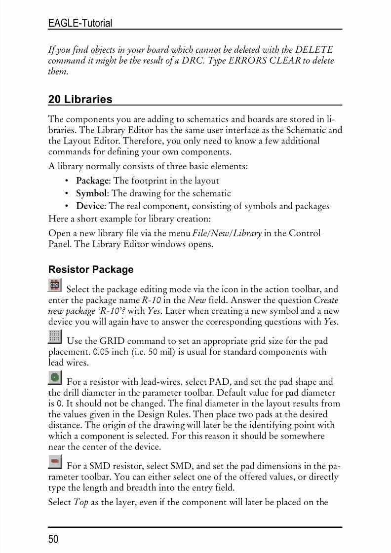
ResistorPackage
Selectthepackageeditingmodeviatheiconintheactiontoolbar,andenterthepackagename R-10 inthe New field.Answerthequestion Createnewpackage‘R-10’? with Yes.Laterwhencreatinganewsymbolandanew deviceyouwillagainhavetoanswerthecorrespondingquestionswith Yes.
UsetheGRIDcommandtosetanappropriategridsizeforthepadplacement.0.05inch(i.e.50mil)isusualforstandardcomponentswithleadwires.
Foraresistorwithlead-wires,select PAD,andsetthepadshapeandthedrilldiameterintheparametertoolbar.Defaultvalueforpaddiameteris0.Itshouldnotbechanged.ThefinaldiameterinthelayoutresultsfromthevaluesgivenintheDesignRules. Thenplacetwopadsatthedesireddistance.Theoriginofthedrawingwilllaterbetheidentifyingpointwithwhichacomponentisselected.Forthisreasonitshouldbesomewherenearthecenterofthedevice.
ForaSMDresistor,selectSMD,andsetthepaddimensionsinthepa-rametertoolbar.Youcaneitherselectoneoftheofferedvalues,ordirectly
typethelengthandbreadthintotheentryfield.
Select Top asthelayer,evenifthecomponentwilllaterbeplacedonthe
50
EAGLE-Tutorial

8/6/2019 Tutorial Eng
http://slidepdf.com/reader/full/tutorial-eng 51/57
undersideoftheboard.SMDcomponentsarelocatedontheothersideofaboardusingtheMIRRORcommand.Thismovestheelementsinallthet..-layersintothecorresponding b..-layers.
PlacethetwoSMDpads(whichinEAGLEarejustcalledSMDs)atthede-
sireddistance.TouseroundSMDs(BGAs)defineasquareonefirst,thenCHANGEthevaluefor Roundness =100%.
Youcannowenterthenames,suchas 1 and 2,forthepadsorSMDsusingtheNAMEcommand.
Adifferentprocedureishoweverrecommendedforcomponentswithmanysequentiallynumberedpads:
SelectthePADcommand,typeinthenameofthefirstpad,e.g. '1' (thein-vertedcommasmustalsobeentered),thenplacethepadsinsequence.
NowusetheWIREcommandtodrawthesilkscreensymbolinlayer21 tPlace.Thislayercontainswhatwillbeprintedontheboard.Itisuptoyouhowmuchdetailyougivetothesymbol.Setafinergridsizeifithelps.
Taketheinformationprovidedin library.txt (in eagle/doc)asaguidelineforthedesignofcomponents.YoumayalsousetheARC,CIRCLE,RECTandPOLYGONcommandtodrawsilkscreensymbols.
Pleasetakecareinlayer21 tPlace nottocoveranyareasthathavetobesol-dered.Inlayer51 tDocu amorerealisticappearancecanbegivenwhichisnotsubjecttothislimitation.Layer51 tDocu isnotusedtoprintontotheboarditself,butisasupplementtothegraphicalpresentationwhichmightbeusedforprintdocumentation.Intheexampleoftheresistor,thesymbolcanbedrawninlayer21 tPlace,butthewires,whichgooverthepads,aredrawninlayer51 tDocu.
WiththeTEXTcommandyouplacethetexts >NAME inlayer25
tNames and >VALUE inlayer27 tValues inthoseplaceswhereintheboardtheactualnameandtheactualvaluearetoappear.
SMASHandMOVEcanbeusedlatertochangethepositionofthistextrelativetothepackagesymbolontheboard.
TheCHANGEcommandcanbeusedatalaterstagetoalterobjectpropertiessuchasthestrokethicknessoftexts( ratio),textheight,orthelayerinwhichtheobjectislocated.
Ifyouwanttochangethepropertiesofseveralobjectsatonego,defineagroupwiththeGROUPcommand,clicktheCHANGEcommand,selecttheparameterandthevalue,andclickintothegroupwiththe right mouse
51
EAGLE-Tutorial

8/6/2019 Tutorial Eng
http://slidepdf.com/reader/full/tutorial-eng 52/57
button.
Example:UseGROUPtodefineagroupthatcontainsbothpads,thenselectCHANGEandSHAPE/SQUARE.Clickonthedrawingsurfacewiththerightmousebutton.Theshapeofbothpadschanges.
TheDESCRIPTIONcommandallowsaninfotextaboutthepackage.Thistextandthepackage'snamewillbetakeninconsiderationbythesearchfunctionoftheADDcommand.
ResistorSymbol
Selectthesymboleditingmode,andenterthesymbolname R inthe New field.Thisnameonlyhasameaninginternaltotheprogram,anddoes
notappearintheschematic.Nowcheckthat0.1inchissetasthegridsize.Thepinsinthesymbol mustbeplacedonthisgrid,sincethisiswhatEAGLEexpects.
SelectthePINcommand.Youcannowsetthepropertiesofthesepinsintheparametertoolbar,beforeplacingthemwiththeleftmousebutton.AllthesepropertiescanbechangedatalaterstagewiththeCHANGEcommand.Groupscanagainbedefined(GROUP)whosepropertiescanthenbealteredwithCHANGEandthe right mousebutton.Seehelpfunc-
tionforfurtherdetails.TheNAMEcommandallowsyoutonamepinsaftertheyhavebeen
placed.
Theschematicsymbolisdrawninlayer94 Symbols usingWIREandtheotherdrawingcommands.Placethetexts >NAME and >VALUEinthelayer95 Names and96 Values (TEXTcommand).Placethemwherethenameandvalueofthecomponentaretoappearintheschematic.
Forfineadjustmentchooseafinergrid.ThiscanbedonewhiletheTEXTcommandisactive.Afterwardschangethegridtodefaultvalue0.1inchagain.
ResistorDevice
Createthenewdevice R-10 withthisicon.WhenyoulaterusetheADDcommandtofetchthecomponentintotheschematic,youwillselectitbyusingthisname.Itisonlyacoincidencethatinthiscasethenameof
thepackageandthenameofthedevicearethesame.Todefinedevicesthatareavailableinseveraltechnologiesandpackagevari-antsyouhavetousewildcardsinthedevicenametodeterminethe
52
EAGLE-Tutorial
8/6/2019 Tutorial Eng
http://slidepdf.com/reader/full/tutorial-eng 53/57
positionofthesenames.* representsthepositionofthetechnologyname, ? thepackagename.De-finingforexampleadevicelikea7400intwotechnologies(L, LS)thecor-rectdevicenameis 74*00.Thenameofthepackagevariantwillbeaddedat
theendofthenameautomatically.Ifyouwishtoseethepackagevariant'sname,forexample,atthebeginningofthedevicenameyouhavetousethe?likethis: ?74*00.
Clickthe New buttonontherightlowerareaoftheDeviceEditorwindow toassignapackage.Forourexample,pleasechoosethepackage R-10.Toallowfurtherpackagevariantsclick New again.
ThePREFIXcommandisusedtospecifyaprefixforaname.Thenameitselfwillinitiallybeautomaticallyallocatedintheschematic.Foraresistorthiswould,naturallyenough,be R.TheresistorswillthenbeidentifiedasR1,R2,R3etc..ThenamescanbealteredatanytimewiththeNAMEcommand.
YoucanspecifywiththeVALUEcommandwhetherthedevice’svaluecanbealteredintheschematicorintheboard.Valuemustbe On forresistors.Forotherdevicesitmaybewisetosetvalue Off .
ThepreviouslydefinedresistorsymbolisfetchedintothedevicewiththeADDcommand.
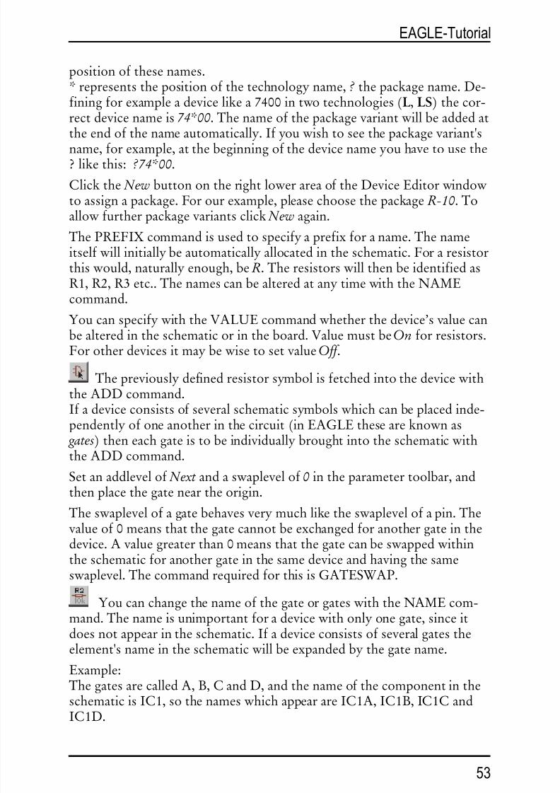
Ifadeviceconsistsofseveralschematicsymbolswhichcanbeplacedinde-pendentlyofoneanotherinthecircuit(inEAGLEtheseareknownas gates)theneachgateistobeindividuallybroughtintotheschematicwiththeADDcommand.
Setanaddlevelof Next andaswaplevelof 0 intheparametertoolbar,andthenplacethegateneartheorigin.
Theswaplevelofagatebehavesverymuchliketheswaplevelofapin.Thevalueof0meansthatthegatecannotbeexchangedforanothergateinthedevice.Avaluegreaterthan0meansthatthegatecanbeswappedwithin
theschematicforanothergateinthesamedeviceandhavingthesameswaplevel.ThecommandrequiredforthisisGATESWAP.
YoucanchangethenameofthegateorgateswiththeNAMEcom-mand.Thenameisunimportantforadevicewithonlyonegate,sinceitdoesnotappearintheschematic.Ifadeviceconsistsofseveralgatestheelement'snameintheschematicwillbeexpandedbythegatename.
Example:ThegatesarecalledA,B,CandD,andthenameofthecomponentintheschematicisIC1,sothenameswhichappearareIC1A,IC1B,IC1CandIC1D.
53
EAGLE-Tutorial

8/6/2019 Tutorial Eng
http://slidepdf.com/reader/full/tutorial-eng 54/57
WiththeCONNECTcommandyouspecifywhichpinsaretakentowhichpackagepads.
Clickthe Connect buttonnow.
TheConnectwindow
InthisexampletheresistorgatehasbeennamedG$1automatically.ThisisthereasonwhyyouseethepinnameG$1.1andG$1.2inthecolumn Pins.Thecolumn Pad showsthepadsplacedinthepackage.Clickonapinandapadentryandclickthe Connect button.Ifyouwanttodisconnectapinfromapad,selectthepairinthe Connection columnandclick Disconnect.OK endstheCONNECTcommandandclosesthewindow.
YoucanenterinformationconcerningthedeviceafterclickingtheDESCRIPTIONcommand.TheenteredtextwillbedisplayedintheCon-trolPanel,whenyouselectthedeviceinthetreeview.ItwillalsobecheckedbythesearchfunctionoftheADDcommand.
Nowthedefinitionoftheresistoriscomplete.Youcanuseitinasche-maticnow.
54
EAGLE-Tutorial

8/6/2019 Tutorial Eng
http://slidepdf.com/reader/full/tutorial-eng 55/57
TheDeviceEditor
21 OutputofDrawingsandManufacturingDataEAGLEcanoutputdrawings,forexamplefordocumentationpurposes,usingthePRINTcommand.Thiscommandcanbefoundinthe File menusoftheSchematicorLayoutEditor.
YoucanusetheprintersdefinedunderWindowswiththiscommand.TheLinuxversiongeneratesPostscriptfilesthatcanbesentto lpr ortoafile.
Aprintoutofthedrawingintheactiveeditorwindowwiththeactuallayersettings(DISPLAYcommand)willbegenerated.
FilmandmanufacturingdataaregeneratedwiththeCAMProcessor.StartitwiththeiconintheactiontoolbaroftheLayoutEditorwindow.
TheCAMProcessorusesitsowndrivers,whichcanbedefinedormodifiedbytheuser(seefile eagle.def indirectory eagle/bin).
Dataforabillofmaterial,formounting,millingortestingmachinesetc.canbegeneratedwiththehelpofEAGLEUserLanguagePrograms.Infor-mationaboutULP'scanbefoundinthefileheadersorwiththehelpofthedescriptionsintheControlPanel.
55
EAGLE-Tutorial

8/6/2019 Tutorial Eng
http://slidepdf.com/reader/full/tutorial-eng 56/57
OutputaSchematicwiththePRINTCommand
Theschematic demo1.sch istobeprintedinblack/whiteandfullformatononepage.
Loadthefile demo1.sch andclickthePRINTiconintheactiontoolbar.Checktheboxes Black, Solid and Rotate (asthedrawingisinlandscapefor-mat).Theboxes Mirror and Upsidedown arenotmarked.
Forboth Scalefactor and Pagelimit typein 1.Thisspecifiesthatthedraw-ingistobeoutputatascalefactorof1,provideditfitsontoonepage.If not,EAGLEchangesthescalefactor,sothatthedrawingdoesfitontoonepage.With Pagelimit 0thedrawingwillalwaysbeprintedwiththesetscalefactor.
Theprintercanbeselectedbyusingthebutton Printer.
Thebutton Page leadsyoutothepagesetupparameters.Ifthebox Captionischecked,thedrawingwillbeprintedwithafooter,containingthefilename,date,time,andscalefactor.
GeneratingGerberDatawiththeCAMProcessor
Thesamestepsareusuallyrequiredforeachboardwheneverfilmsandmanufacturingdataaregenerated.ThisprocesscanbedefinedasaCAMProcessorjob.
Thefile gerber.cam,whichcanbefoundinthedefaultsubdirectoryforCAMjobs,automatestheoutputofGerberdatafordoublesidedboards.
Attention: TheprocessdescribedcanonlybeusedforGerberphotoplotters with flexible aperturewheels,notforphotoplotterswithfixedaperturewheels.
Pleasecontactyourboardhousetoconfirmwhichdataareneeded.
LoadthejobintotheCAMProcessor,eitherbydouble-clickingtheentrywiththename gerber.cam intheControlPanel'streeview(CAMJobs),or
byclickingtheCAMProcessoriconintheLayoutEditorwindowandse-lecting gerber.cam inthefiledialog(⇒ File/Open/Job).
IncaseyouhavestartedtheCAMprocessorfromtheControlPanel,loadtheboardfile demo3.brd:
⇒ File/Open/Board and • • demo3.brd
Clickthebutton ProcessJob andconfirmbothprompts Deletename.$$$...and Morethan... with • OK .
Nowallofthenecessaryfileswillbewrittenintothe Project directory
(wherethedrawingandboardfilesforthisprojectarelocated).
Thefileshavethefollowingmeanings:
56
EAGLE-Tutorial

8/6/2019 Tutorial Eng
http://slidepdf.com/reader/full/tutorial-eng 57/57
demo3.cmp Componentside
demo3.sol Solderside
demo3.plc Silkscreenforcomponentside
demo3.stc Solderingmaskforthecomponentsidedemo3.sts Solderingmaskforthesolderside
demo3.whl Aperturewheelfile
demo3.gpi Informationfile,notrelevant
demo3.$$$ Temporaryfile,tobedeleted
Thefirstsixfilesneedtobesenttoyourboardmanufacturer.
Drillingdatacanbegeneratedaccordinglybyusingthejob excellon.cam.
BeforeyoustarttheCAMprocessoryouhavetogeneratea Rackfile whichcontainsatoollistforthedrillingmachine.Togenerateit,starttheUserLanguageprogram drillcfg.ulp withtheRUNcommandintheLayoutEdi-torwindow.TheULPgeneratesafile boardname.drl thatwillbereadbytheCAMProcessor.
FurtherinformationcanbefoundontheCAMProcessorhelppages.
22 DataExchangewithEAGLEUserLanguage
EAGLEcomeswithanintegratedC-likeUserLanguageinterpreterwhichhasaccesstovirtuallyalldata(inEAGLEorexternalfiles).UserLanguageprogramscancreateanyfiletypeandthereforegenerateanydataformatusedbyothersoftwareorhardware.Agoodexampleisthefile bom.ulpwhichgeneratesabillofmaterial.
Pleasehavealookatthefileswiththeextension *.ulp andtheUserLan-guagesectionofthehelpfunctiontogetabetterideaofthepossibilitiesin-herentintheprogram.
AdditionalUserLanguageprogramscanbefoundonourwebpages:http:wwwcadsoftusacomdownloadhtm (UserFilesdirectory).
23 ScriptFiles-FlexibleInputInterface
ScriptfilesaretextfileswhichcancontainanyEAGLEcommand(see
EAGLE-Tutorial