tutorial - automationdirect 41 tutorial • determine how the pushbuttons, leds, plc messages, and...
TRANSCRIPT

44444TTTTTutorialutorialutorialutorialutorial
In this chapter....— EZText Panel Setup— Installing EZText Programming Software— Installation Screens— Tutorial
Plan the Project using Application WorksheetsCreate the Project using EZText Programming SoftwareConfigure a PLC
40 EZ-TEXT-M
TUTORIAL
SETUP ModeIn order to download the program to theEZText Panel using the EZText PanelProgramming Software, you must be in theSetup Mode. Setup Mode is also where youwill adjust the display contrast of theEZText Panel.
The EZText Panel will start up in the RUN Mode. To access the SETUP Mode,follow these steps:
1. Press the UP Arrow Pushbutton and hold while simultaneouslypressing the DOWN Arrow Pushbutton to enter the SETUP Mode.
2. At any time you may press the Escape (esc) button to go back toRUN Mode. You will be taken back to the start of the Local Messagemenu (cursor is placed at root level when you return from setup).
Adjust Display ContrastYou may only adjust the Display Contrast when in Setup Mode. To adjust thedisplay contrast use the UP and DOWN arrows to increase or decrease thecontrast.
Internal Software and Hardware RevisionsWhile in SETUP Mode the Panel Hardware Revision, Driver Revision, BootRevision, and Exec (Firmware) Revision numbers will display on the panel.
Preparing for ConfigurationIf you prepare and plan ahead of time, your use of the EZText PanelProgramming software will be successful. Below are a few important steps totake to prepare to program your application.
• Prepare your personal computer and ensure proper installation of theEZText Panel Programming Software
• Know your operator interface requirements. Determine the type ofEZText Panel and the number of EZText Panels required by yourapplication
• Know your PLC type and available resources, such as, programmingtools, CPU capabilities, user memory, etc.
• Verify type of communications port, as well as protocol used.Determine the CPU link(s) available for connecting an EZText Panel(RS-232/RS-422, baud rate, parity, stop bits.)
EZText Panel Setup
SETUP MODEDRV. REV.:

41EZ-TEXT-M
TUTORIAL
• Determine how the pushbuttons, LEDs, PLC Messages, and LocalMessages will be assigned in your panels with respect to yourmachine or process.
• To prepare your application, use the application worksheets providedin appendix A of this manual. The example worksheets will helpyou understand how the EZText Panel program is configured. Blankworksheets can be used in planning, implementing, and using yourEZText Panels.
Installing EZText Programming SoftwareEZText Panels are configured with software running on an IBM or compatiblepersonal computer. This software is available through Automationdirect.com,part number EZ-TEXTEDIT. The software is used to download yourconfiguration before connecting the panel and communicating with a PLC. HelpTopics are provided to help you configure your panel. You design and configureyour EZText Panel program off-line and save it to disk. The program may thenbe transferred to the EZText Panel. To install EZText Programming Software,perform the following steps:
• Place the CD into your CD ROM Drive.
• From Windows click on the Start Button, and then click onRun from the menu. The Run dialog box will pop up.
• At the prompt type D:\ (or your CD Drive)\setup.exe or clickon the Browse Button and find the Setup.exe file forEZText Programming Software.
• Click on the OK button to begin the installation. TheEZText Programming Software Installation Screen willappear.
• Follow the onscreen prompts to load the software.

42 EZ-TEXT-M
TUTORIAL
This is the final installation screen. Hereyou select the destination folder whereyour software program will be installed.The default destination location is C:\Program Files\EZText. If you wish to selectanother destination, click on the Browsebutton.
To complete the installation, click on Next>button. That’s all there is to it! The EZTextIcon shown above will appear on yourdesktop. Simply click on it to open theProgramming Software!
➥
➥This icon willappear on yourdesktop afterinstallation.
EZTEZTEZTEZTEZTeeeeextxtxtxtxtPrPrPrPrProgrammingogrammingogrammingogrammingogrammingSoftware IconSoftware IconSoftware IconSoftware IconSoftware Icon
➡
➡
Installation Screens

43EZ-TEXT-M
TUTORIAL
The following is a project tutorial. It will take you through the process of creatinga new project, configuring buttons, creating messages, and transferring aproject to the EZText Panel. This should help familiarize you with the EZTextProgramming Software.
Let’s start by filling out the application worksheet found in Appendix A. Fortutorial purposes, we have already filled in the information. For your project,make copies of the forms in Appendix A. Follow steps 1 through 4 as shownbelow to fill out the application worksheet for the EZText Demo Project.
Tutorial — Plan the Project using Application Worksheets
1 Fill in the Project andPLC information.
2 Assign a PLC Word(V40600) to the buttonsand to the PanelAcknowledge (if usingPanel Set/ PLC Releasefor Button Action). Seenext page.
3 Assign a PLC Word(V40601) to the LEDControl (if using By PLC)and PLC Button Release(if using Panel Set & PLCRelease Button Action).See next page.
4 Assign a PLC Wordfor each PLCMessage Line.
1
3
2
4

44 EZ-TEXT-M
TUTORIAL
This is a copy of page 29 from Chapter 3, Learning the Features. Shown hereare the bit addresses for the Button PLC Word (V40600) and LED PLC Word(V40601) in this tutorial.
Please note that any unused bit address SHOULD NOT BE USED in yourPLC program. The EZText Panel will control the unused bits.

45EZ-TEXT-M
TUTORIAL
For the next part of our project planning, we’ll create four Local Messagesusing the Local Message Worksheet. These messages will be configured laterin our EZText Demo Project using the EZText Programming Software.
1 Add a Folderat Level 1
2 Add a Messageunder the Folderat Level 2
3 Add anotherMessage at Level2. This Message isa READ Only withone data pointDATA1).
4 Add anotherMessage at Level 2.This Message is aREAD/WRITE fordata entry with onedata point (DATA1)with a min. andmax. value range.
4
3
2
1
46 EZ-TEXT-M
TUTORIAL
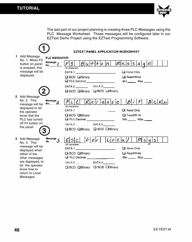
The last part of our project planning is creating three PLC Messages using thePLC Message Worksheet. These messages will be configured later in ourEZText Demo Project using the EZText Programming Software.
1
2
3
1 Add MessageNo. 1. When F3button on panelis pressed, thismessage will bedisplayed.
2 Add MessageNo. 2. Thismessage will bedisplayed to letthe operatorknow that thePLC has turnedoff F4 button onthe panel.
3 Add MessageNo. 3. Thismessage will bedisplayed wheneither of theother messagesare displayed, tolet the operatorknow how toreturn to LocalMessages.
47EZ-TEXT-M
TUTORIAL
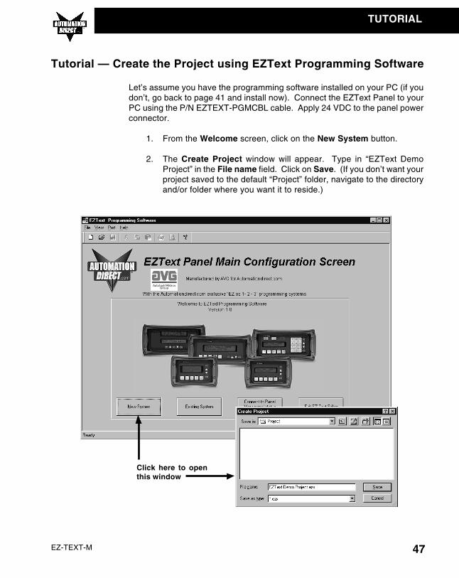
Let’s assume you have the programming software installed on your PC (if youdon’t, go back to page 41 and install now). Connect the EZText Panel to yourPC using the P/N EZTEXT-PGMCBL cable. Apply 24 VDC to the panel powerconnector.
1. From the Welcome screen, click on the New System button.
2. The Create Project window will appear. Type in “EZText DemoProject” in the File name field. Click on Save. (If you don’t want yourproject saved to the default “Project” folder, navigate to the directoryand/or folder where you want it to reside.)
Tutorial — Create the Project using EZText Programming Software
Click here to openthis window

48 EZ-TEXT-M
TUTORIAL
3. In Step 1, Select Panel, you will start your project by selecting thepanel type you are using.
a. From the Main Configuration Screen, click on the Select PanelType button.
b. The Select Panel dialog box will open. Under Panel Type, clickon the panel type you are using to highlight it. A picture of thepanel will appear under Panel Preview, and key features of thepanel are displayed under Panel Attributes.
c. Click on the OK button to select and close the dialog box.
4. In Step 2, Select PLC, you will choose the type PLC you are using.
a. Click on the DOWN arrow next to the Select PLC field to view thedrop down menu of available PLCs. Click on the PLC Type toselect.
Click here to openthis window
Click here toselect
49EZ-TEXT-M
TUTORIAL
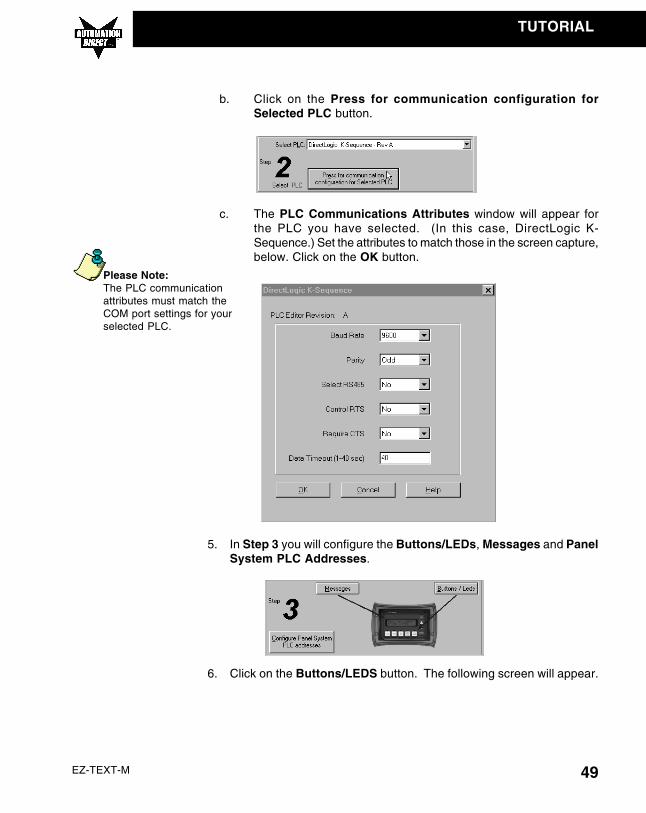
b. Click on the Press for communication configuration forSelected PLC button.
c. The PLC Communications Attributes window will appear forthe PLC you have selected. (In this case, DirectLogic K-Sequence.) Set the attributes to match those in the screen capture,below. Click on the OK button.
5. In Step 3 you will configure the Buttons/LEDs, Messages and PanelSystem PLC Addresses.
6. Click on the Buttons/LEDS button. The following screen will appear.
Please Note:The PLC communicationattributes must match theCOM port settings for yourselected PLC.

50 EZ-TEXT-M
TUTORIAL
a. Under LED Control, click on the down arrow to view controlchoices. Select By Button for LED 1, LED 3 and LED 4. SelectBy PLC for LED 2, and By Button & Flash for LED 5 (selectionsshould be as shown in the screen capture above).
b. Under Button Action, click on the down arrow to view controlchoices. Select Alternate for F1 and F5, Momentary for F2 andF3, and Panel Set & PLC Release for F4.
c. Assign a PLC Word for the LEDs and the Buttons. These PLCWords should be a BIT Register.
d. Click on OK to accept and exit the screen.
LED Control
Button Action
LED PLC Word
Button PLC Word
51EZ-TEXT-M
TUTORIAL
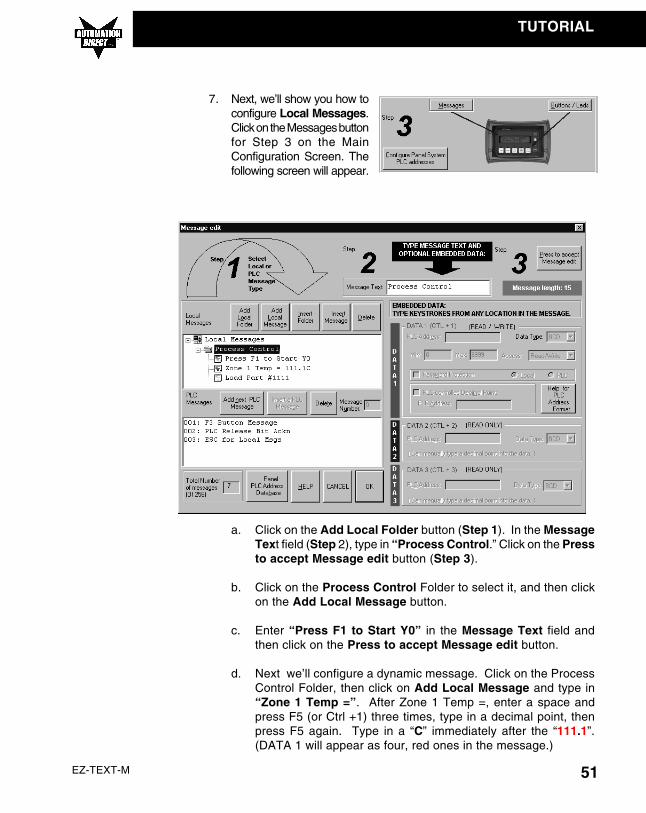
7. Next, we’ll show you how toconfigure Local Messages.Click on the Messages buttonfor Step 3 on the MainConfiguration Screen. Thefollowing screen will appear.
a. Click on the Add Local Folder button (Step 1). In the MessageText field (Step 2), type in “Process Control.” Click on the Pressto accept Message edit button (Step 3).
b. Click on the Process Control Folder to select it, and then clickon the Add Local Message button.
c. Enter “Press F1 to Start Y0” in the Message Text field andthen click on the Press to accept Message edit button.
d. Next we’ll configure a dynamic message. Click on the ProcessControl Folder, then click on Add Local Message and type in“Zone 1 Temp =”. After Zone 1 Temp =, enter a space andpress F5 (or Ctrl +1) three times, type in a decimal point, thenpress F5 again. Type in a “C” immediately after the “111.1”.(DATA 1 will appear as four, red ones in the message.)

52 EZ-TEXT-M
TUTORIAL
e. Under the DATA 1 section of the screen shown above, type in“V2010” in the PLC Address field. The Data Type should beset to BCD, and Access should be Read Only.
f. Click on the Press to accept Message edit button.
g. The last Local Message to be configured will be an Interactivemessage (DATA 1).
h. Click on the Process Control Folder, then click on Add LocalMessage.
i. In the Message Text field, typein “Load Part #”, leave a space,and then press F5, or Ctrl + 1, fourtimes. (DATA 1 will appear in theMessage Text field as four, redones.)
j. The DATA 1 configuration area is now available (no longer grayedout.) Next to PLC Address, type in “V2011”. Data Type shouldbe BCD. Access is Read/Write. Set the Min. value to “1200”and the Max. value to “1999” (settings are shown in the screencapture, above.) This will limit what value can be entered by theoperator.
k. Click on the Press to accept Message edit button to save it.

53EZ-TEXT-M
TUTORIAL
8. To create PLC Messages 001, 002, and 003 as shown in the screencapture above, perform the following steps:
a. Click on the Add next PLC Message button.
b. Type in the Message Text field, “F3 Button Message”.
c. Click on the Press to accept Message edit button to save it.
d. Click on the Add next PLC Message button.
e. Type in the Message Text field, “PLC Release Bit Ackn”.
f. Click on the Press to accept Message edit button to save it.
g. Click on the Add next PLC Message button.
h. Type in the Message Text field, “ESC for Local Msgs”.
i. Click on the Press to accept Message edit button to save it.
9. You are now finished configuring the messages for this tutorial, clickon OK to exit the Message Edit screen.
10. The final part of Step 3 isto configure the panelsystem PLC addresses.To configure PLCaddresses, click on theConfigure Panel SystemPLC addresses button.

54 EZ-TEXT-M
TUTORIAL
11. The Panel System PLC Address Setup screen will appear. Entersettings as follows:
a. Type in “V3000” in the Line One field. Select BCD as the DATAType. Type in “V3001” in the Line Two field. Select BCD as theDATA Type.
b. The panel beeper is defaulted to Yes. If you do not want to hearthe beeper each time a button is pressed, select No under EnableBeeper.
c. Click on the OK button to save and exit.
12. You are now ready to write the project to the EZText Panel.
13. Click on the Write to Panel button on the Main Configuration Screen.
PLC Messages Setup
Enable Beeper
55EZ-TEXT-M
TUTORIAL
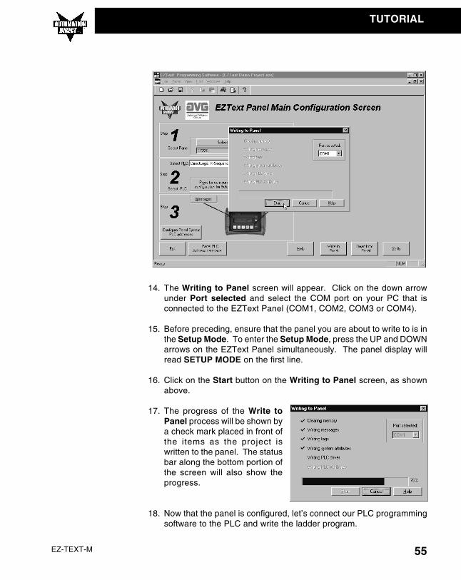
14. The Writing to Panel screen will appear. Click on the down arrowunder Port selected and select the COM port on your PC that isconnected to the EZText Panel (COM1, COM2, COM3 or COM4).
15. Before preceding, ensure that the panel you are about to write to is inthe Setup Mode. To enter the Setup Mode, press the UP and DOWNarrows on the EZText Panel simultaneously. The panel display willread SETUP MODE on the first line.
16. Click on the Start button on the Writing to Panel screen, as shownabove.
17. The progress of the Write toPanel process will be shown bya check mark placed in front ofthe items as the project iswritten to the panel. The statusbar along the bottom portion ofthe screen will also show theprogress.
18. Now that the panel is configured, let’s connect our PLC programmingsoftware to the PLC and write the ladder program.

56 EZ-TEXT-M
TUTORIAL
Tutorial — Configure a PLC
For the purposes of this tutorial, we will be using a DirectLogic® DL05 PLC.To configure the PLC we are using DirectSOFT® Programming Software. Thepurpose of this part of the tutorial is to show you how to configure your PLC tocommunicate with an EZText Panel.
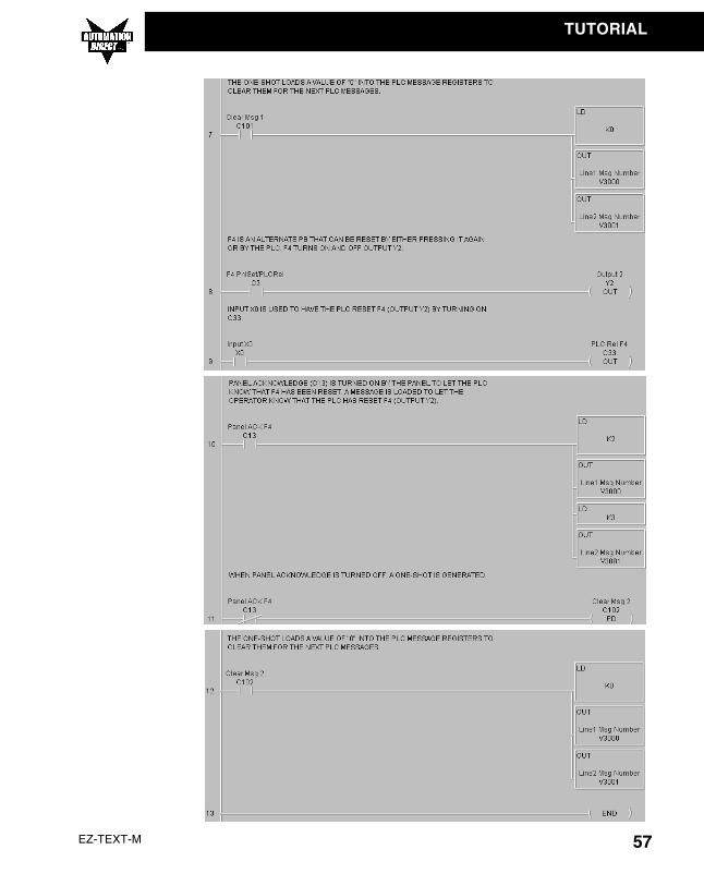
1. Connect to the PLC with DirectSOFT.
2. Enter the following ladder logic.
57EZ-TEXT-M
TUTORIAL

58 EZ-TEXT-M
TUTORIAL
3. Save the Program to the PLC and to disk (EZTextDemoProject).
4. Place the PLC in Run Mode.
The PLC is now configured and running. Now, to test our project, connect thePanel to PLC communications cable (P/N EZ-2CBL), to the panel port and thePLC port.
1. Press the esc (escape) button on the EZText panel. The LocalMessage (folder), “+ Process Control”, will be displayed on the firstline.
2. Press the enter button to open the folder. Level 2 Local Message“Press F1 to Start Y0” will be displayed. Use the ����������(arrow) buttonsto scroll through the messages. Press the esc button to go back tothe Folder Level 1.
3. Press F1 to turn ON or OFF Y0.
4. Press F2 to turn ON Y1 for 5 seconds.
5. Press F3 to display PLC Message No. 1.
6. Press F4 to turn ON Y2. Either press F4 again to turn it OFF, or turnON X0 in the PLC. If the PLC turns OFF F4, a message will bedisplayed.
7. Press F5 to see an alternate button with flashing LED.
CONGRATULATIONS! You have now successfully configured an EZText Panel!