tutorial 10. using multiple rotating reference framesbarbertj/cfd training/fluent 12/tut...using...
TRANSCRIPT
Tutorial 10. Using Multiple Rotating Reference Frames
Introduction
Many engineering problems involve rotating flow domains. One example is the centrifugalblower unit that is typically used in automotive climate control systems. For problemswhere all the moving parts (fan blades, hub and shaft surfaces, etc.) are rotating ata prescribed angular velocity, and the stationary walls (e.g., shrouds, duct walls) aresurfaces of revolution with respect to the axis of rotation, the entire domain can bereferred to as a single rotating frame of reference. However, when each of the severalparts is rotating about a different axis of rotation, or about the same axis at differentspeeds, or when the stationary walls are not surfaces of revolution (such as the volutearound a centrifugal blower wheel), a single rotating coordinate system is not sufficientto “immobilize” the computational domain so as to predict a steady-state flow field.
In ANSYS FLUENT, the flow features associated with multiple rotating parts can beanalyzed using the multiple reference frame (MRF) capability. This model is powerfulin that multiple rotating reference frames can be included in a single domain. Theresulting flow field is representative of a snapshot of the transient flow field in which therotating parts are moving. However, in many cases the interface can be chosen in sucha way that the flow field at this location is independent of the orientation of the movingparts. In other words, if an interface can be drawn on which there is little or no angulardependence, the model can be a reliable tool for simulating time-averaged flow fields. Itis therefore very useful in complicated situations where one or more rotating parts arepresent.
This tutorial illustrates the procedure for setting up and solving a problem using theMRF capability. As an example, the flow field on a 2D section of a centrifugal blowerwill be calculated. The example will be limited to a single rotating reference frame.
This tutorial demonstrates how to do the following:
• Specify different frames of reference for different fluid zones.
• Set the relative velocity of each wall.
• Calculate a solution using the pressure-based solver.
Release 12.0 c© ANSYS, Inc. March 12, 2009 10-1
Using Multiple Rotating Reference Frames
Prerequisites
This tutorial is written with the assumption that you have completed Tutorial 1, andthat you are familiar with the ANSYS FLUENT navigation pane and menu structure.Some steps in the setup and solution procedure will not be shown explicitly.
In general, to solve problems using the MRF feature, you should be familiar with theconcept of creating multiple fluid zones in your mesh generator.
Problem Description
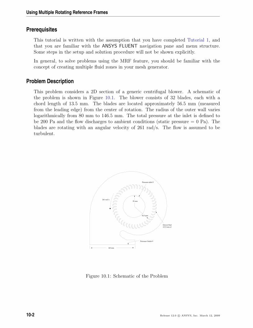
This problem considers a 2D section of a generic centrifugal blower. A schematic ofthe problem is shown in Figure 10.1. The blower consists of 32 blades, each with achord length of 13.5 mm. The blades are located approximately 56.5 mm (measuredfrom the leading edge) from the center of rotation. The radius of the outer wall varieslogarithmically from 80 mm to 146.5 mm. The total pressure at the inlet is defined tobe 200 Pa and the flow discharges to ambient conditions (static pressure = 0 Pa). Theblades are rotating with an angular velocity of 261 rad/s. The flow is assumed to beturbulent.
t
145 mm
261 rad/s35 mm
56.5 mm
Pressure-inlet-5
blower blades(13.5 mm chord length)
Pressure-Outlet-9
Figure 10.1: Schematic of the Problem
10-2 Release 12.0 c© ANSYS, Inc. March 12, 2009
Using Multiple Rotating Reference Frames
Setup and Solution
Preparation
1. Download multiple_rotating.zip from the User Services Center to your workingfolder (as described in Tutorial 1).
2. Unzip multiple_rotating.zip.
The file, blower.msh can be found in the multiple rotating folder created afterunzipping the file.
3. Use FLUENT Launcher to start the 2D version of ANSYS FLUENT.
For more information about FLUENT Launcher, see Section 1.1.2 in the separateUser’s Guide.
Note: The Display Options are enabled by default. Therefore, once you read in the mesh,it will be displayed in the embedded graphics window.
Step 1: Mesh
1. Read the mesh file (blower.msh) in the ANSYS FLUENT serial solver.
File −→ Read −→Mesh...
The mesh file is opened in the serial solver because the Smooth/Swap... operationis available only in serial ANSYS FLUENT.
Step 2: General Settings
General
1. Check the mesh.
General −→ Check
ANSYS FLUENT will perform various checks on the mesh and will report the progressin the console. Make sure that the reported minimum volume is a positive number.
Release 12.0 c© ANSYS, Inc. March 12, 2009 10-3
Using Multiple Rotating Reference Frames
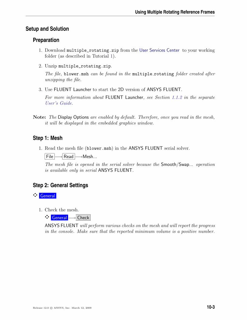
2. Smooth and swap the mesh.
Mesh −→Smooth/Swap...
The smooth and swap function is available only in serial ANSYS FLUENT. If youwant to solve using ANSYS FLUENT parallel, you can do so only after node smooth-ing and face swapping. Node smoothing and face swapping will improve the meshquality. This step is recommended for triangular and tetrahedral meshes.
(a) Retain the default smoothing parameters and click Smooth.
(b) Click Swap repeatedly until the Number Swapped in the Swap Info group boxis zero.
(c) Close the Smooth/Swap Mesh dialog box.
3. Check the mesh.
General −→ Check
Note: It is a good practice to check the mesh after you manipulate it (i.e., scale,convert to polyhedra, merge, separate, fuse, add zones, or smooth and swap.)This will ensure that the quality of the mesh has not been compromised.
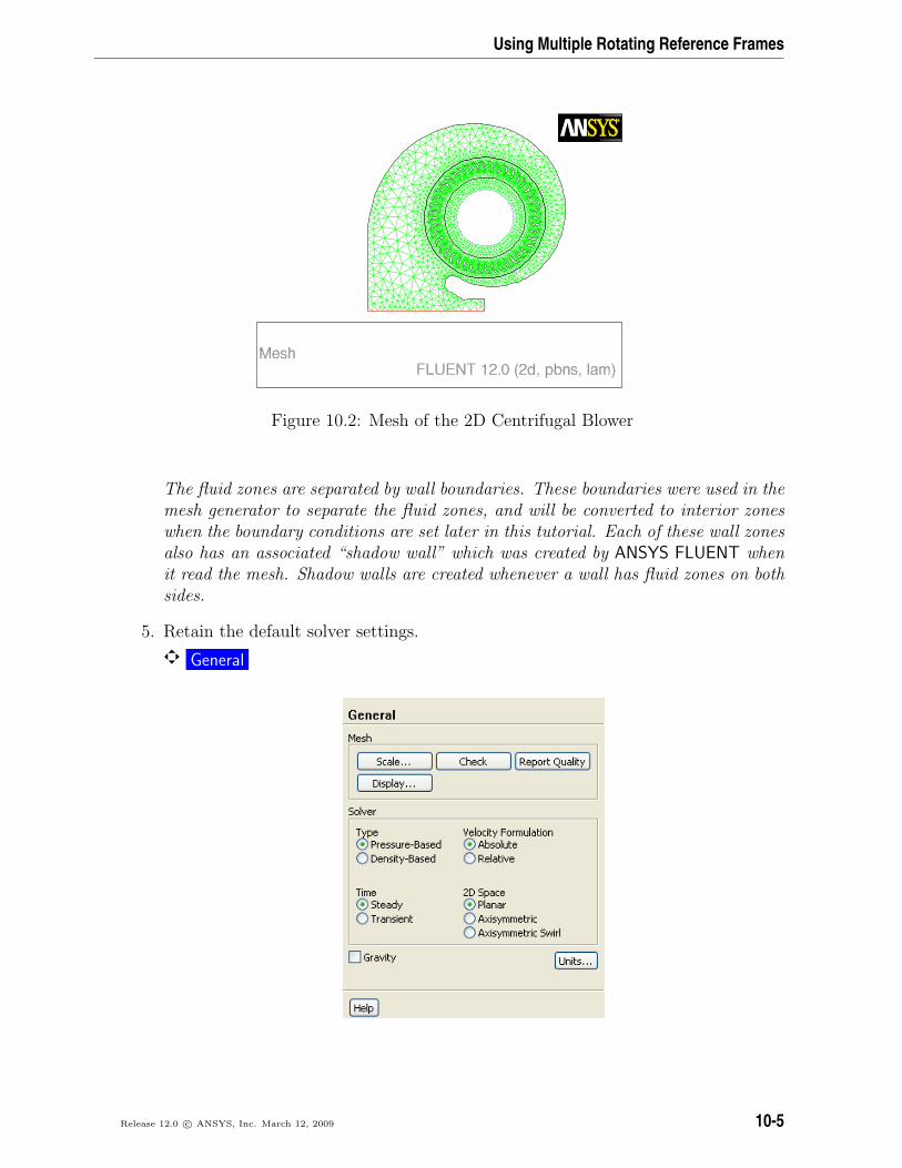
4. Examine the mesh (Figure 10.2).
The mesh consists of three fluid zones, fluid-13, fluid-14, and fluid-18. These arereported in the console when the mesh is read. In the Mesh Display dialog box, thefluid zones are reported as interior zones interior-61, interior-62 and interior-66. Ina later step, you will learn how to associate a fluid zone with an interior zone. Thefluid zone containing the blades will be solved in a rotational reference frame.
10-4 Release 12.0 c© ANSYS, Inc. March 12, 2009
Using Multiple Rotating Reference Frames
Figure 10.2: Mesh of the 2D Centrifugal Blower
The fluid zones are separated by wall boundaries. These boundaries were used in themesh generator to separate the fluid zones, and will be converted to interior zoneswhen the boundary conditions are set later in this tutorial. Each of these wall zonesalso has an associated “shadow wall” which was created by ANSYS FLUENT whenit read the mesh. Shadow walls are created whenever a wall has fluid zones on bothsides.
5. Retain the default solver settings.
General
Release 12.0 c© ANSYS, Inc. March 12, 2009 10-5
Using Multiple Rotating Reference Frames
Step 3: Models
Models
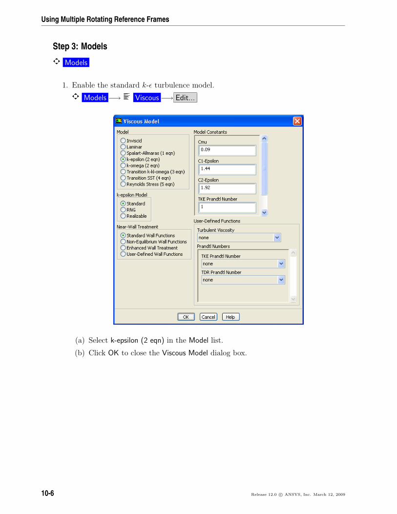
1. Enable the standard k-ε turbulence model.
Models −→ Viscous −→ Edit...
(a) Select k-epsilon (2 eqn) in the Model list.
(b) Click OK to close the Viscous Model dialog box.
10-6 Release 12.0 c© ANSYS, Inc. March 12, 2009
Using Multiple Rotating Reference Frames
Step 4: Materials
Materials
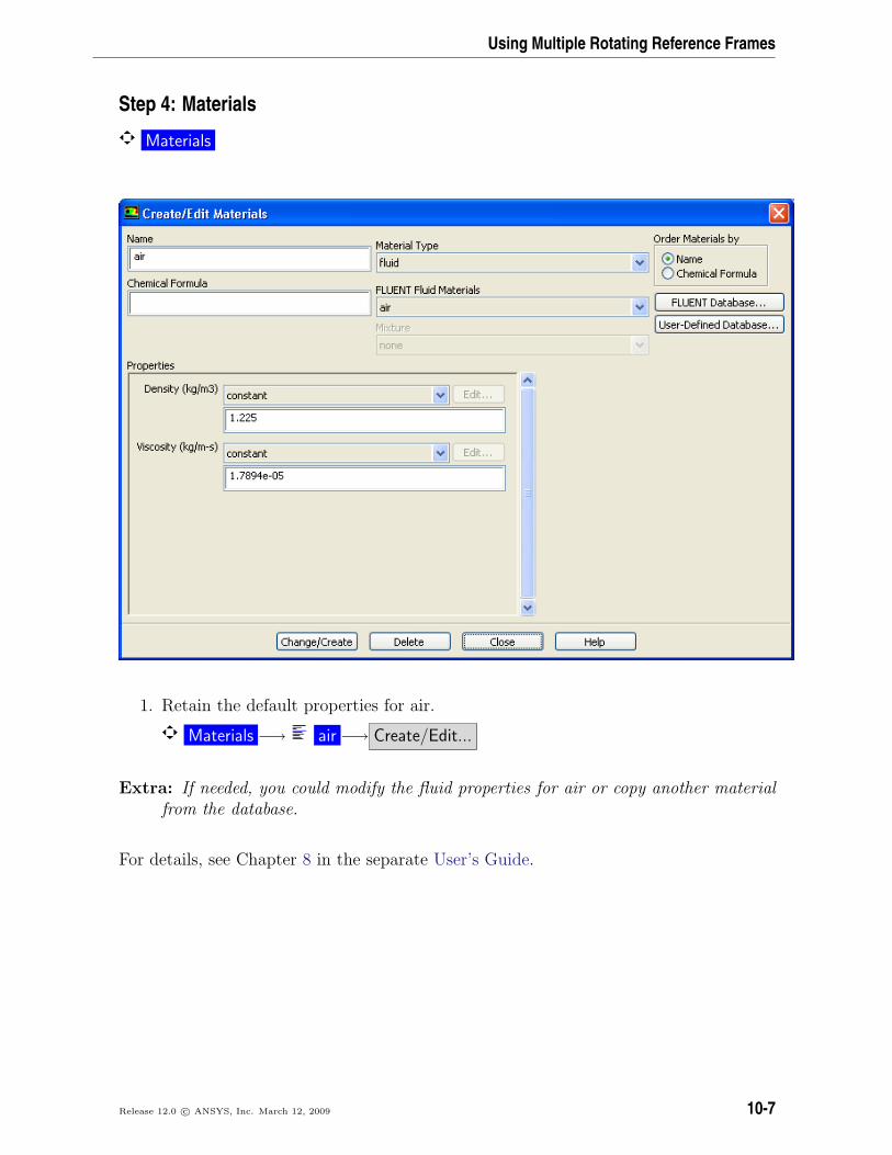
1. Retain the default properties for air.
Materials −→ air −→ Create/Edit...
Extra: If needed, you could modify the fluid properties for air or copy another materialfrom the database.
For details, see Chapter 8 in the separate User’s Guide.
Release 12.0 c© ANSYS, Inc. March 12, 2009 10-7
Using Multiple Rotating Reference Frames
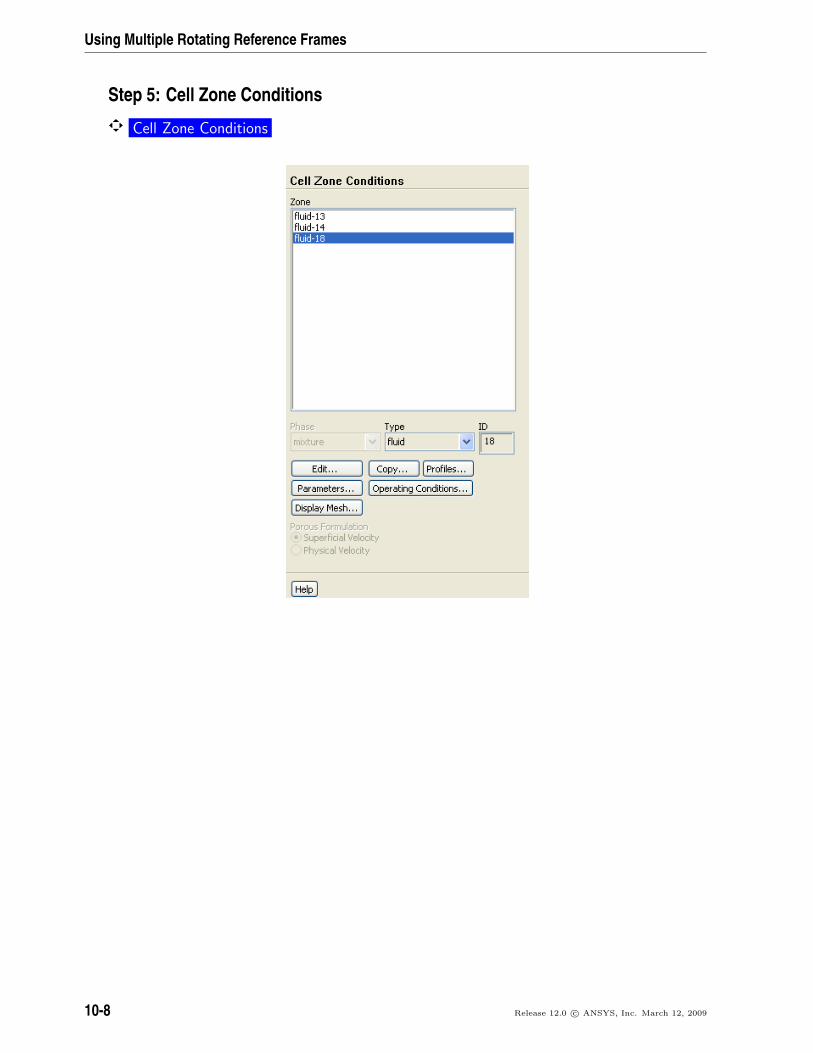
Step 5: Cell Zone Conditions
Cell Zone Conditions
10-8 Release 12.0 c© ANSYS, Inc. March 12, 2009
Using Multiple Rotating Reference Frames
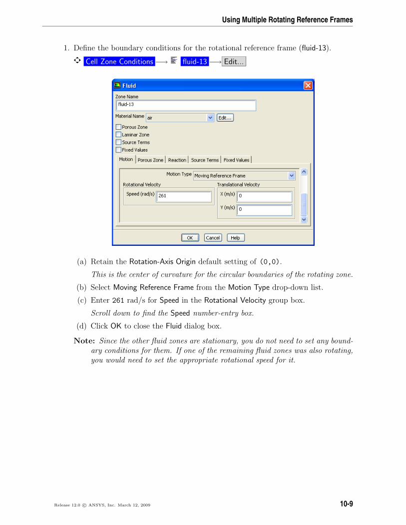
1. Define the boundary conditions for the rotational reference frame (fluid-13).
Cell Zone Conditions −→ fluid-13 −→ Edit...
(a) Retain the Rotation-Axis Origin default setting of (0,0).
This is the center of curvature for the circular boundaries of the rotating zone.
(b) Select Moving Reference Frame from the Motion Type drop-down list.
(c) Enter 261 rad/s for Speed in the Rotational Velocity group box.
Scroll down to find the Speed number-entry box.
(d) Click OK to close the Fluid dialog box.
Note: Since the other fluid zones are stationary, you do not need to set any bound-ary conditions for them. If one of the remaining fluid zones was also rotating,you would need to set the appropriate rotational speed for it.
Release 12.0 c© ANSYS, Inc. March 12, 2009 10-9
Using Multiple Rotating Reference Frames
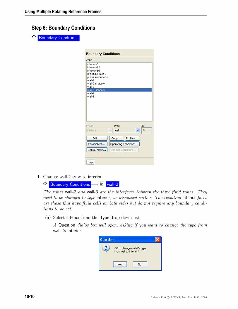
Step 6: Boundary Conditions
Boundary Conditions
1. Change wall-2 type to interior.
Boundary Conditions −→ wall-2
The zones wall-2 and wall-3 are the interfaces between the three fluid zones. Theyneed to be changed to type interior, as discussed earlier. The resulting interior facesare those that have fluid cells on both sides but do not require any boundary condi-tions to be set.
(a) Select interior from the Type drop-down list.
A Question dialog box will open, asking if you want to change the type fromwall to interior.
10-10 Release 12.0 c© ANSYS, Inc. March 12, 2009
Using Multiple Rotating Reference Frames
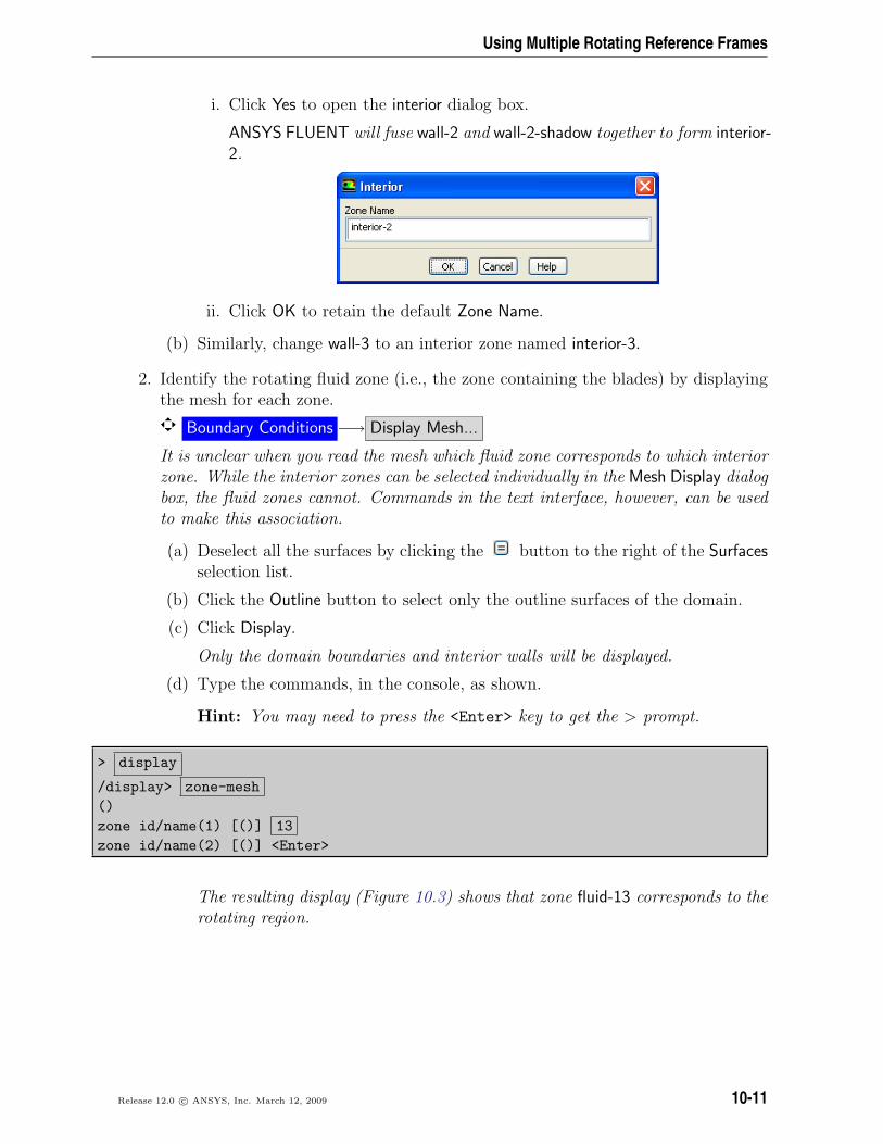
i. Click Yes to open the interior dialog box.
ANSYS FLUENT will fuse wall-2 and wall-2-shadow together to form interior-2.
ii. Click OK to retain the default Zone Name.
(b) Similarly, change wall-3 to an interior zone named interior-3.
2. Identify the rotating fluid zone (i.e., the zone containing the blades) by displayingthe mesh for each zone.
Boundary Conditions −→ Display Mesh...
It is unclear when you read the mesh which fluid zone corresponds to which interiorzone. While the interior zones can be selected individually in the Mesh Display dialogbox, the fluid zones cannot. Commands in the text interface, however, can be usedto make this association.
(a) Deselect all the surfaces by clicking the button to the right of the Surfacesselection list.
(b) Click the Outline button to select only the outline surfaces of the domain.
(c) Click Display.
Only the domain boundaries and interior walls will be displayed.
(d) Type the commands, in the console, as shown.
Hint: You may need to press the <Enter> key to get the > prompt.
> display
/display> zone-mesh()zone id/name(1) [()] 13zone id/name(2) [()] <Enter>
The resulting display (Figure 10.3) shows that zone fluid-13 corresponds to therotating region.
Release 12.0 c© ANSYS, Inc. March 12, 2009 10-11
Using Multiple Rotating Reference Frames
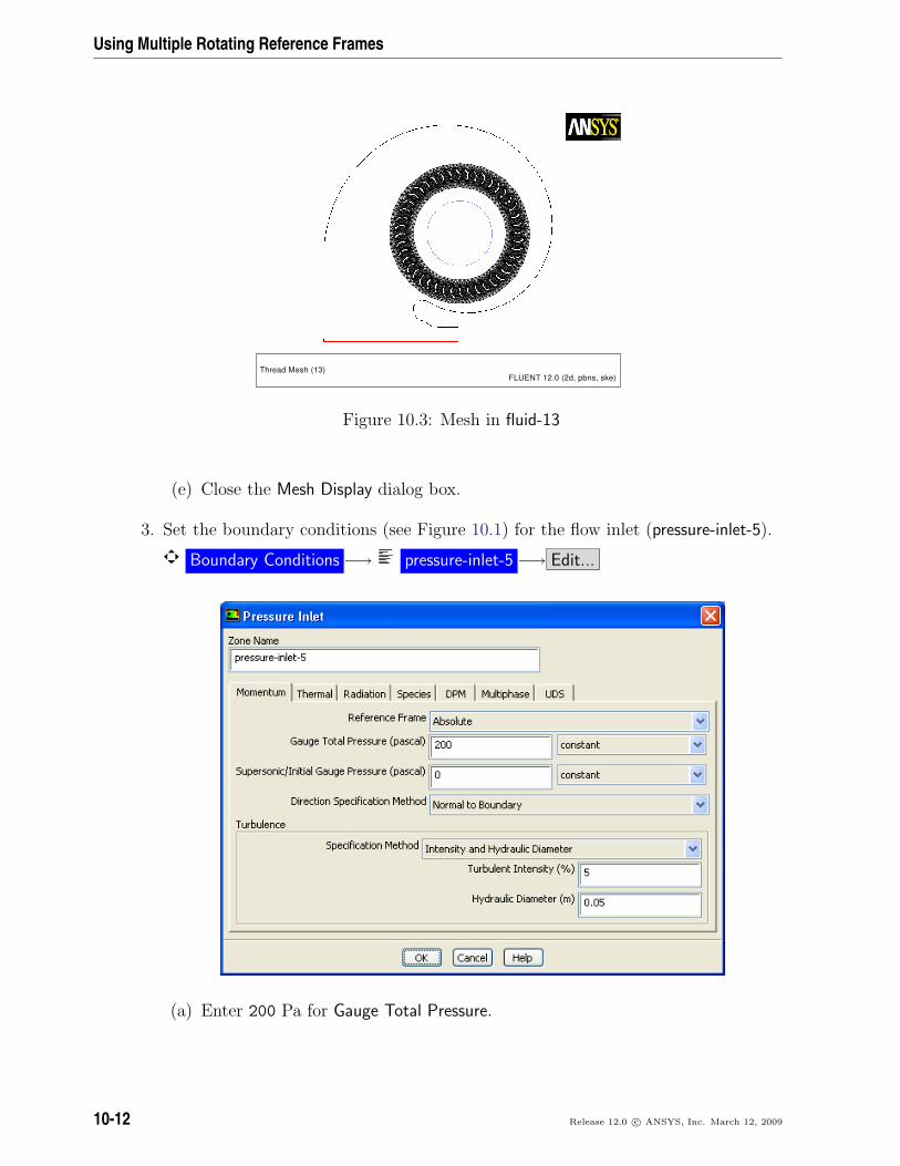
Thread Mesh (13)FLUENT 12.0 (2d, pbns, ske)
Figure 10.3: Mesh in fluid-13
(e) Close the Mesh Display dialog box.
3. Set the boundary conditions (see Figure 10.1) for the flow inlet (pressure-inlet-5).
Boundary Conditions −→ pressure-inlet-5 −→ Edit...
(a) Enter 200 Pa for Gauge Total Pressure.
10-12 Release 12.0 c© ANSYS, Inc. March 12, 2009
Using Multiple Rotating Reference Frames
(b) Select Intensity and Hydraulic Diameter from the Specification Method drop-down list.
(c) Enter 5 % for Turbulent Intensity.
(d) Enter 0.05 m for Hydraulic Diameter.
(e) Click OK to close the Pressure Inlet dialog box.
Note: All pressures that you specify in ANSYS FLUENT are gauge pressures, rela-tive to the operating pressure specified in the Operating Conditions dialog box.By default, the operating pressure is 101325 Pa.
For details, see Section 8.14 in the separate User’s Guide.
4. Set the backflow turbulence parameters for the flow outlet (pressure-outlet-9) to thesame values used for pressure-inlet-5.
Note: The backflow values are used only if reversed flow occurs at the outlet, but itis a good idea to use reasonable values, even if you do not expect any backflowto occur.
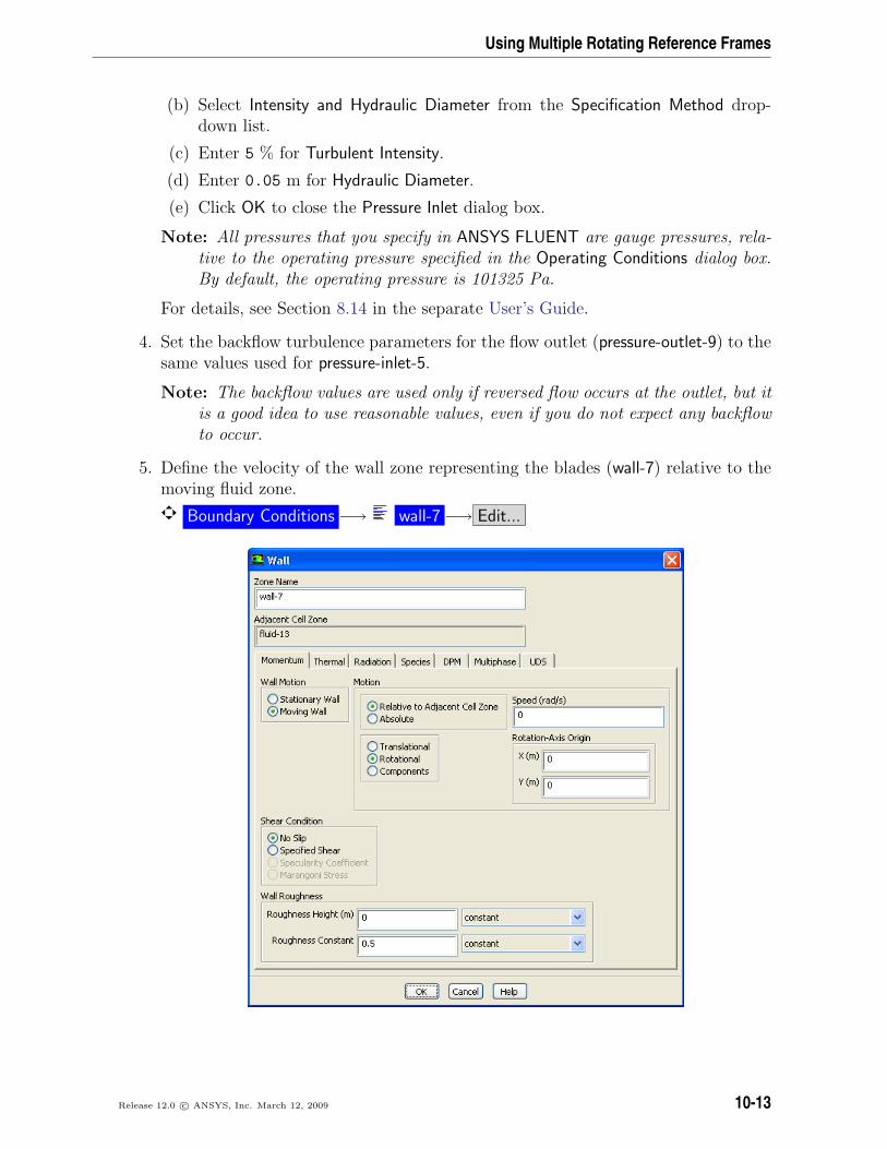
5. Define the velocity of the wall zone representing the blades (wall-7) relative to themoving fluid zone.
Boundary Conditions −→ wall-7 −→ Edit...
Release 12.0 c© ANSYS, Inc. March 12, 2009 10-13
Using Multiple Rotating Reference Frames
With fluid-13 set to a rotating reference frame, wall-7 becomes a moving wall.
(a) Select Moving Wall in the Wall Motion list.
The Wall dialog box will expand to show the wall motion parameters.
(b) Retain the default selection of Relative to Adjacent Cell Zone and select Rota-tional in the Motion group box.
(c) Retain the default value of 0 rad/s for (relative) Speed.
(d) Click OK to close the Wall dialog box.
The Rotation-Axis Origin should be located at x = 0 m and y = 0 m. Withthese settings, the blades will move at the same speed as the surrounding fluid.
Step 7: Solution
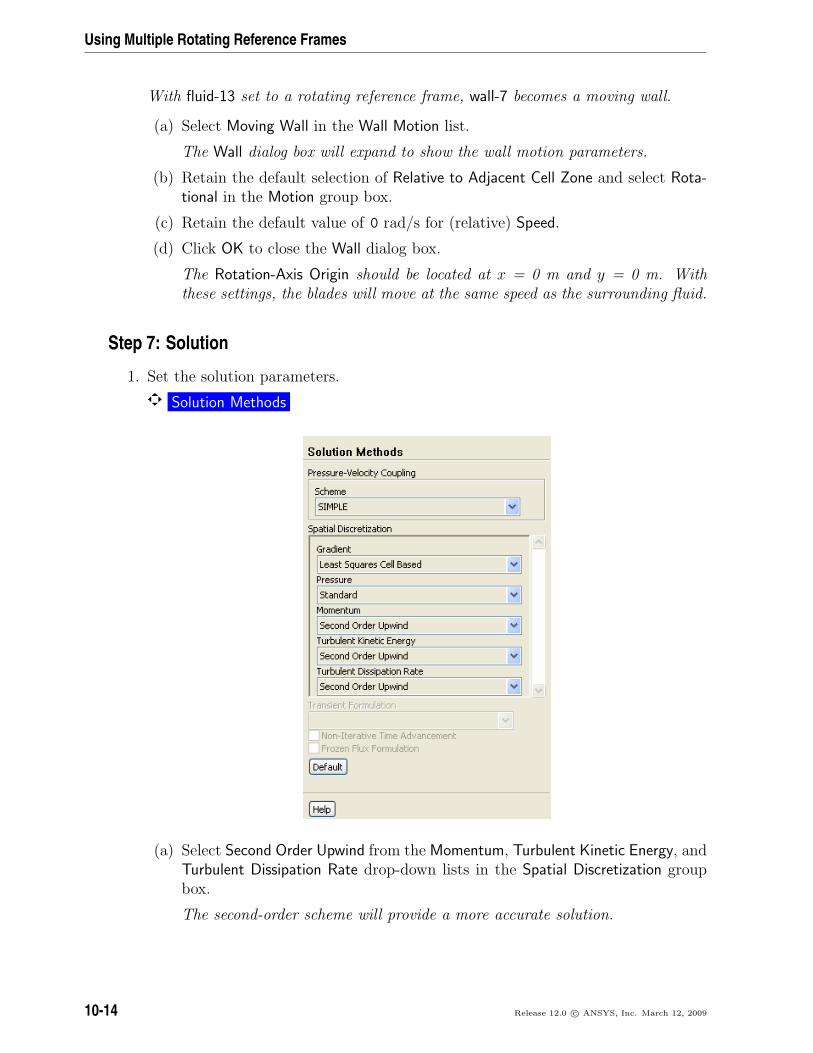
1. Set the solution parameters.
Solution Methods
(a) Select Second Order Upwind from the Momentum, Turbulent Kinetic Energy, andTurbulent Dissipation Rate drop-down lists in the Spatial Discretization groupbox.
The second-order scheme will provide a more accurate solution.
10-14 Release 12.0 c© ANSYS, Inc. March 12, 2009
Using Multiple Rotating Reference Frames
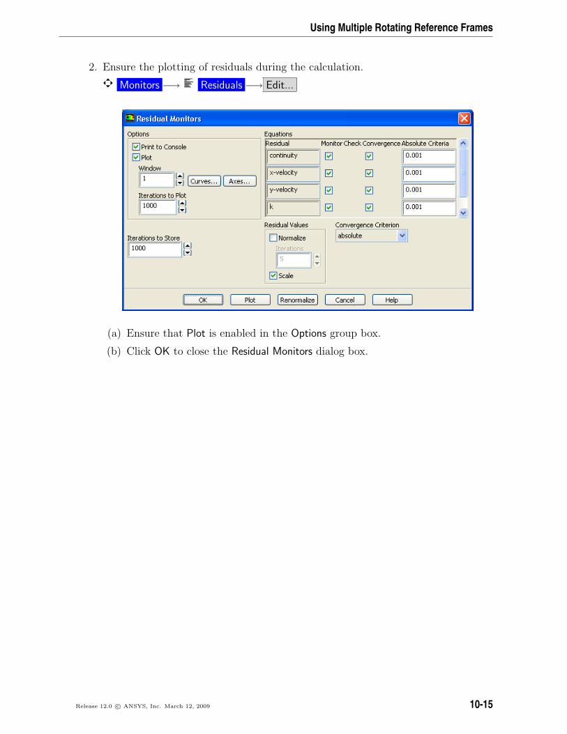
2. Ensure the plotting of residuals during the calculation.
Monitors −→ Residuals −→ Edit...
(a) Ensure that Plot is enabled in the Options group box.
(b) Click OK to close the Residual Monitors dialog box.
Release 12.0 c© ANSYS, Inc. March 12, 2009 10-15

Using Multiple Rotating Reference Frames
3. Initialize the solution using the boundary conditions set at pressure-inlet-5.
Solution Initialization
(a) Select pressure-inlet-5 from the Compute from drop-down list.
(b) Select Absolute in the Reference Frame list.
(c) Click Initialize to initialize the solution.
Note: In this tutorial, you chose an Absolute reference frame for initializing thesolution. In certain cases, Relative to Cell Zone may help the solution convergefaster.
For guidelines, see Section 26.9 in the separate User’s Guide.
4. Save the case file (blower.cas.gz).
File −→ Write −→Case...
10-16 Release 12.0 c© ANSYS, Inc. March 12, 2009
Using Multiple Rotating Reference Frames
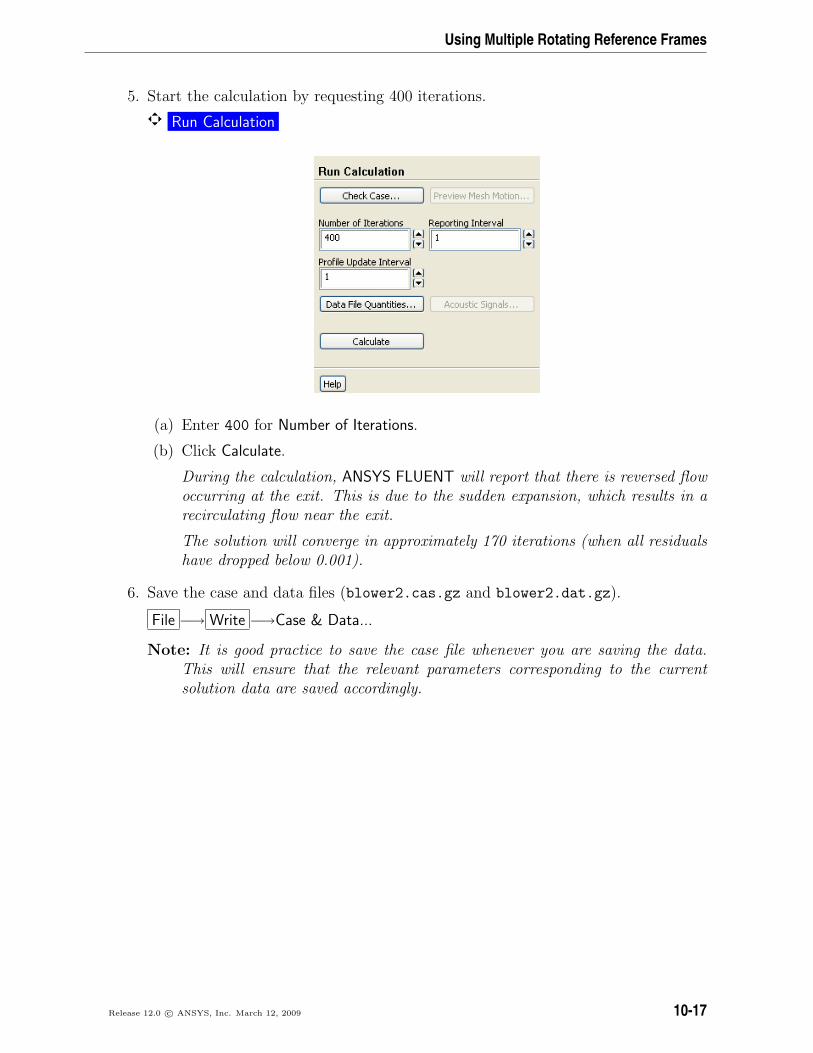
5. Start the calculation by requesting 400 iterations.
Run Calculation
(a) Enter 400 for Number of Iterations.
(b) Click Calculate.
During the calculation, ANSYS FLUENT will report that there is reversed flowoccurring at the exit. This is due to the sudden expansion, which results in arecirculating flow near the exit.
The solution will converge in approximately 170 iterations (when all residualshave dropped below 0.001).
6. Save the case and data files (blower2.cas.gz and blower2.dat.gz).
File −→ Write −→Case & Data...
Note: It is good practice to save the case file whenever you are saving the data.This will ensure that the relevant parameters corresponding to the currentsolution data are saved accordingly.
Release 12.0 c© ANSYS, Inc. March 12, 2009 10-17
Using Multiple Rotating Reference Frames
Step 8: Postprocessing
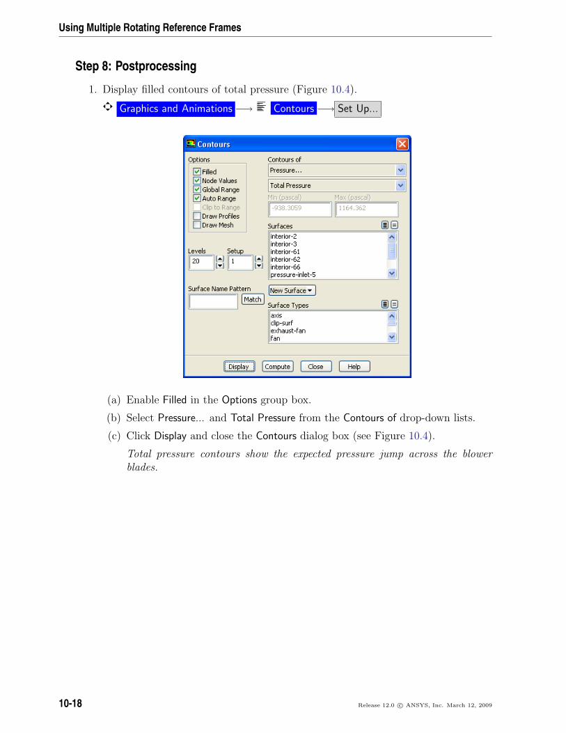
1. Display filled contours of total pressure (Figure 10.4).
Graphics and Animations −→ Contours −→ Set Up...
(a) Enable Filled in the Options group box.
(b) Select Pressure... and Total Pressure from the Contours of drop-down lists.
(c) Click Display and close the Contours dialog box (see Figure 10.4).
Total pressure contours show the expected pressure jump across the blowerblades.
10-18 Release 12.0 c© ANSYS, Inc. March 12, 2009
Using Multiple Rotating Reference Frames
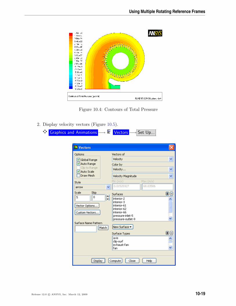
Figure 10.4: Contours of Total Pressure
2. Display velocity vectors (Figure 10.5).
Graphics and Animations −→ Vectors −→ Set Up...
Release 12.0 c© ANSYS, Inc. March 12, 2009 10-19
Using Multiple Rotating Reference Frames
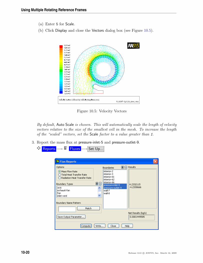
(a) Enter 5 for Scale.
(b) Click Display and close the Vectors dialog box (see Figure 10.5).
Figure 10.5: Velocity Vectors
By default, Auto Scale is chosen. This will automatically scale the length of velocityvectors relative to the size of the smallest cell in the mesh. To increase the lengthof the “scaled” vectors, set the Scale factor to a value greater than 1.
3. Report the mass flux at pressure-inlet-5 and pressure-outlet-9.
Reports −→ Fluxes −→ Set Up...
10-20 Release 12.0 c© ANSYS, Inc. March 12, 2009
Using Multiple Rotating Reference Frames
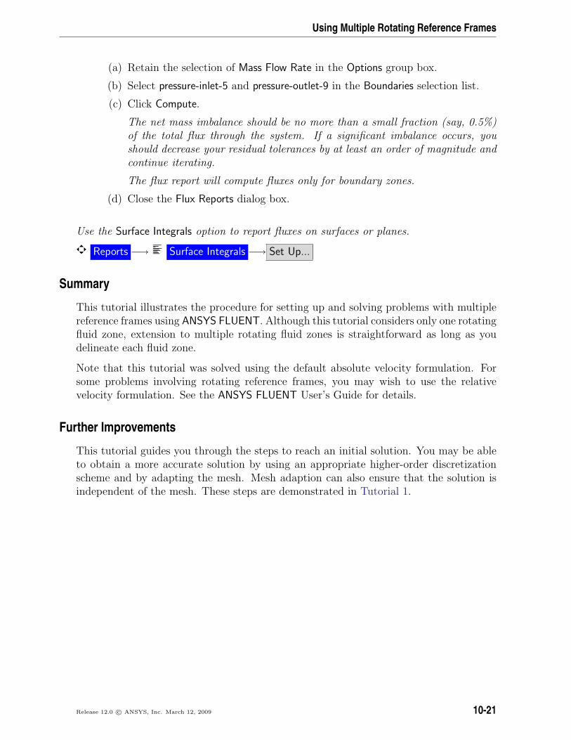
(a) Retain the selection of Mass Flow Rate in the Options group box.
(b) Select pressure-inlet-5 and pressure-outlet-9 in the Boundaries selection list.
(c) Click Compute.
The net mass imbalance should be no more than a small fraction (say, 0.5%)of the total flux through the system. If a significant imbalance occurs, youshould decrease your residual tolerances by at least an order of magnitude andcontinue iterating.
The flux report will compute fluxes only for boundary zones.
(d) Close the Flux Reports dialog box.
Use the Surface Integrals option to report fluxes on surfaces or planes.
Reports −→ Surface Integrals −→ Set Up...
Summary
This tutorial illustrates the procedure for setting up and solving problems with multiplereference frames using ANSYS FLUENT. Although this tutorial considers only one rotatingfluid zone, extension to multiple rotating fluid zones is straightforward as long as youdelineate each fluid zone.
Note that this tutorial was solved using the default absolute velocity formulation. Forsome problems involving rotating reference frames, you may wish to use the relativevelocity formulation. See the ANSYS FLUENT User’s Guide for details.
Further Improvements
This tutorial guides you through the steps to reach an initial solution. You may be ableto obtain a more accurate solution by using an appropriate higher-order discretizationscheme and by adapting the mesh. Mesh adaption can also ensure that the solution isindependent of the mesh. These steps are demonstrated in Tutorial 1.
Release 12.0 c© ANSYS, Inc. March 12, 2009 10-21

Using Multiple Rotating Reference Frames
10-22 Release 12.0 c© ANSYS, Inc. March 12, 2009