tustp 2003 by angel bustamante may 20, 2003 by angel bustamante may 20, 2003 doe project: design and...
TRANSCRIPT

TUSTP 2003TUSTP 2003TUSTP 2003TUSTP 2003
By By Angel BustamanteAngel Bustamante
May 20, 2003May 20, 2003
By By Angel BustamanteAngel Bustamante
May 20, 2003May 20, 2003
DOE Project:DOE Project:Design and Performance of Design and Performance of
Multiphase Distribution ManifoldMultiphase Distribution Manifold
DOE Project:DOE Project:Design and Performance of Design and Performance of
Multiphase Distribution ManifoldMultiphase Distribution Manifold

Introduction
Objectives
Experimental Program
Manifold Design
Future work
TopicsTopicsTopicsTopics

IntroductionIntroductionIntroductionIntroduction
Wells connected to a manifold have a different liquid and Wells connected to a manifold have a different liquid and
gas flowrategas flowrate
Provide and guarantee equal split of gas and liquid flow Provide and guarantee equal split of gas and liquid flow
for downstream separatorsfor downstream separators
Protect downstream metering equipment and provide Protect downstream metering equipment and provide
high accuracy of metering high accuracy of metering
Multiphase distribution manifold, as a flow conditioning Multiphase distribution manifold, as a flow conditioning device:device:
ObjectivesObjectivesObjectivesObjectives
Develop a lab prototype multiphase distribution manifold Develop a lab prototype multiphase distribution manifold
Acquire systematic experimental data for performanceAcquire systematic experimental data for performance evaluationevaluation
Develop a mechanistic model Develop a mechanistic model Design tool Design tool
Performance evaluationPerformance evaluation
System optimizationSystem optimization

Experimental ProgramExperimental ProgramExperimental ProgramExperimental Program
Experimental Facility
Test Matrix
Results
System Operational Envelope
Manifold Operational Envelope
Liquid and Gas Split Ratios
Manifold Resistance Coefficient (Kl)
Transient Performance

Experimental FacilityExperimental FacilityExperimental FacilityExperimental Facility
Liquid Outletsto Micromotion
GLCC # 1
Gas Outlets
Vortex Meter
Vortex Meter
Distribution Manifold
Slug Damper
Rotameters
Liquid line
Gas line
GLCC # 2

Flow Configurations
1 2 3 4
L GL LCASE 1
1 2 3 4
L LL GCASE 2
1 2 3 4
L GL GCASE 3
1 2 3 4
L LG GCASE 4
1 2 3 4
G GL LCASE 5
1 2 3 4
L GG GCASE 6
1 2 3 4
G GL GCASE 7
Test Matrix Test Matrix
Test Matrix Test Matrix
Vsg: 10.5 fts/s to 30.5 ft/s, Vsl: 1.0 ft/s to 2.75 ft/s
1 2 3 4
CASE 8 L/G L/GL/G L/G
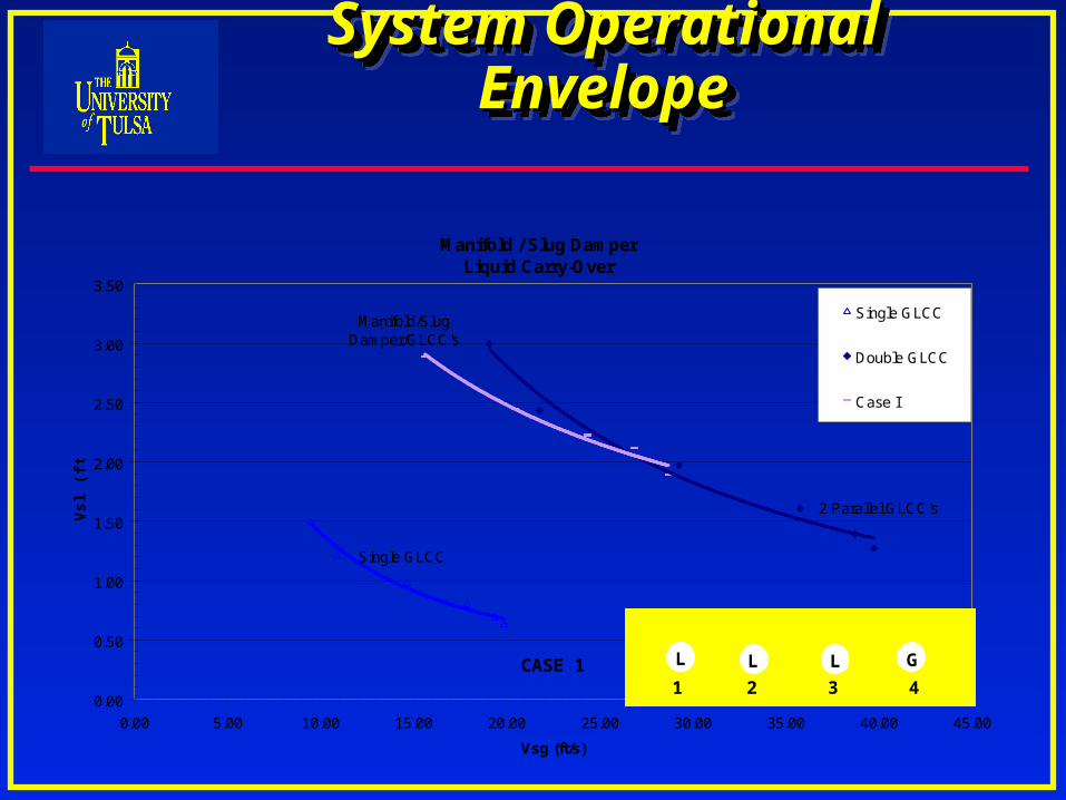
Manifold / Slug DamperLiquid Carry-Over
0.00
0.50
1.00
1.50
2.00
2.50
3.00
3.50
0.00 5.00 10.00 15.00 20.00 25.00 30.00 35.00 40.00 45.00
Vsg (ft/s)
Vs
l (ft
/s)
Single GLCC
Double GLCC
Case I
Single GLCC
2 Parallel GLCC's
Manifold/Slug Damper/GLCC's
System Operational EnvelopeSystem Operational EnvelopeSystem Operational EnvelopeSystem Operational Envelope
1 2 3 4
L GL LCASE 1

Manifold / Slug DamperLiquid Carry-Over
0.00
0.50
1.00
1.50
2.00
2.50
3.00
3.50
0.00 5.00 10.00 15.00 20.00 25.00 30.00 35.00 40.00 45.00
Vsg (ft/s)
Vs
l (ft
/s)
Single GLCC
Double GLCC
Case II
Single GLCC
2 Parallel GLCC's
Manifold/Slug Damper/GLCC
's
1 2 3 4
L LL GCASE 2
System Operational EnvelopeSystem Operational EnvelopeSystem Operational EnvelopeSystem Operational Envelope

Manifold / Slug DamperLiquid Carry-Over
0.00
0.50
1.00
1.50
2.00
2.50
3.00
3.50
0.00 5.00 10.00 15.00 20.00 25.00 30.00 35.00 40.00 45.00
Vsg (ft/s)
Vs
l (ft
/s)
Single GLCC
Double GLCC
Case III
Single GLCC
2 Parallel GLCC's
Manifold/Slug Damper/GLCC
1 2 3 4
L GL GCASE 3
System Operational EnvelopeSystem Operational EnvelopeSystem Operational EnvelopeSystem Operational Envelope

Manifold / Slug DamperLiquid Carry-Over
0.00
0.50
1.00
1.50
2.00
2.50
3.00
3.50
0.00 5.00 10.00 15.00 20.00 25.00 30.00 35.00 40.00 45.00
Vsg (ft/s)
Vs
l (ft
/s)
Single GLCC
Double GLCC
Case VI
Single GLCC
2 Parallel GLCC's
Manifold/Slug Damper/GLCC
's
1 2 3 4
L GG GCASE 6
System Operational EnvelopeSystem Operational EnvelopeSystem Operational EnvelopeSystem Operational Envelope

Manifold / Slug DamperLiquid Carry-Over
0.00
0.50
1.00
1.50
2.00
2.50
3.00
3.50
0.00 5.00 10.00 15.00 20.00 25.00 30.00 35.00 40.00 45.00
Vsg (ft/s)
Vs
l (ft
/s)
Single GLCC
Double GLCC
Case VII
Single GLCC
2 Parallel GLCC's
Manifold/Slug Damper/GLCC'
s
1 2 3 4
G GL GCASE 7
System Operational EnvelopeSystem Operational EnvelopeSystem Operational EnvelopeSystem Operational Envelope

Manifold / Slug DamperLiquid Carry-Over
0.00
0.50
1.00
1.50
2.00
2.50
3.00
3.50
0.00 5.00 10.00 15.00 20.00 25.00 30.00 35.00 40.00 45.00
Vsg (ft/s)
Vs
l (ft
/s)
Single GLCC
Double GLCC
Case VIII Equal Flow
Single GLCC
2 Parallel GLCC's
Manifold/Slug Damper/GLC
C's
1 2 3 4
CASE 8 L/G L/GL/G L/G
THE SAME ENVELOPE APPLIES TO CASES IV AND V
1 2 3 4
L LG G
CASE 4
1 2 3 4
G GL L
CASE 5
System Operational EnvelopeSystem Operational EnvelopeSystem Operational EnvelopeSystem Operational Envelope

Manifold Operational EnvelopeManifold Operational EnvelopeManifold Operational EnvelopeManifold Operational Envelope
Manifold Operational Envelope for Liquid Carry-Over
0.0
0.5
1.0
1.5
2.0
2.5
3.0
5 10 15 20 25 30 35
Vsg (ft/s)
Vs
l (ft
/s)
Case I
Case II
Case III
Case IV
Case V
Case VI
Case VII
Case VIII Equal Flow
Manifold Operational Envelope for Liquid Carry-Over
0.0
0.5
1.0
1.5
2.0
2.5
3.0
3.5
5 10 15 20 25 30 35 40 45
Vsg (ft/s)
Vs
l (ft
/s)
Case I
Case II
Case III
Case IV
Case V
Case VI
Case VII
Case VIII Equal Flow
Single GLCC
2 Parallel GLCC's
Manifold/Slug Damper/GLCC's

Liquid Split ( GLCC# 2 over Total Flow) v.s. GVF
0.40
0.50
0.60
0.70
0.80
0.90
1.00
0.75 0.8 0.85 0.9 0.95 1
GVF
Liq
uid
Sp
lit
Case I
Case III
Case VI1 2 3 4
L GL LCASE 1
1 2 3 4
L GL GCASE 3
1 2 3 4
L GG GCASE 6
Liquid Split RatiosLiquid Split RatiosLiquid Split RatiosLiquid Split Ratios

Liquid Split ( GLCC# 2 over Total Flow) v.s. GVF
0.40
0.50
0.60
0.70
0.80
0.90
1.00
0.75 0.8 0.85 0.9 0.95 1
GVF
Liq
uid
Sp
lit
Case IV
Case V
Case VIIIEqual Flow
1 2 3 4
L LG GCASE 4
1 2 3 4
G GL LCASE 5
1 2 3 4
CASE 8 L/G L/GL/G L/G
Liquid Split RatiosLiquid Split RatiosLiquid Split RatiosLiquid Split Ratios

Liquid Split ( GLCC# 2 over Total Flow) v.s. GVF
0.40
0.50
0.60
0.70
0.80
0.90
1.00
0.75 0.8 0.85 0.9 0.95 1
GVF
Liq
uid
Sp
lit
Case II
Case VII 1 2 3 4
L LL GCASE 2
1 2 3 4
G GL GCASE 7
Liquid Split RatiosLiquid Split RatiosLiquid Split RatiosLiquid Split Ratios
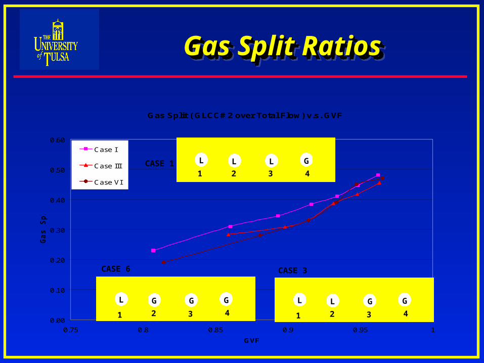
Gas Split ( GLCC# 2 over Total Flow) v.s. GVF
0.00
0.10
0.20
0.30
0.40
0.50
0.60
0.75 0.8 0.85 0.9 0.95 1
GVF
Ga
s S
pli
t
Case I
Case III
Case VI1 2 3 4
L GL LCASE 1
1 2 3 4
L GL G
CASE 3
1 2 3 4
L GG G
CASE 6
Gas Split RatiosGas Split RatiosGas Split RatiosGas Split Ratios

Gas Split ( GLCC# 2 over Total Flow) v.s. GVF
0.00
0.10
0.20
0.30
0.40
0.50
0.60
0.75 0.8 0.85 0.9 0.95 1
GVF
Ga
s S
pli
t
Case IV
Case V
Case VIIIEqual Flow
1 2 3 4
L LG GCASE 4
1 2 3 4
G GL LCASE 5
1 2 3 4
CASE 8 L/G L/GL/G L/G
Gas Split RatiosGas Split RatiosGas Split RatiosGas Split Ratios
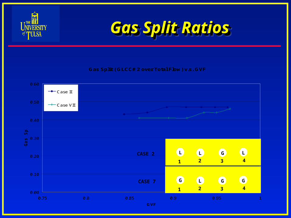
Gas Split ( GLCC# 2 over Total Flow) v.s. GVF
0.00
0.10
0.20
0.30
0.40
0.50
0.60
0.75 0.8 0.85 0.9 0.95 1
GVF
Ga
s S
pli
t
Case II
Case VII
1 2 3 4
L LL GCASE 2
1 2 3 4
G GL GCASE 7
Gas Split RatiosGas Split RatiosGas Split RatiosGas Split Ratios
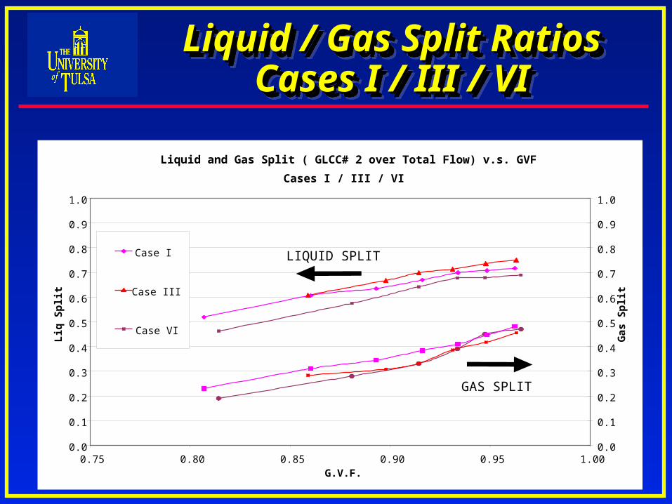
Liquid / Gas Split RatiosLiquid / Gas Split RatiosCases I / III / VICases I / III / VI
Liquid / Gas Split RatiosLiquid / Gas Split RatiosCases I / III / VICases I / III / VI
Liquid and Gas Split ( GLCC# 2 over Total Flow) v.s. GVF
Cases I / III / VI
0.0
0.1
0.2
0.3
0.4
0.5
0.6
0.7
0.8
0.9
1.0
0.75 0.80 0.85 0.90 0.95 1.00G.V.F.
Liq
Sp
lit
0.0
0.1
0.2
0.3
0.4
0.5
0.6
0.7
0.8
0.9
1.0
Gas
Sp
lit
Case I
Case III
Case VI
LIQUID SPLIT
GAS SPLIT

Resistance Coefficient (Kl) for Manifold
Manifold Resistance CoefficientManifold Resistance CoefficientManifold Resistance CoefficientManifold Resistance Coefficient
LIQ
WELLWELL
LIQ
WELLWELL
hh h h
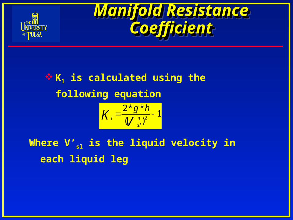
Kl is calculated using the following equation
1)(
**22'
VK
sll
hg
Where V’sl is the liquid velocity in each liquid leg
Manifold Resistance CoefficientManifold Resistance CoefficientManifold Resistance CoefficientManifold Resistance Coefficient
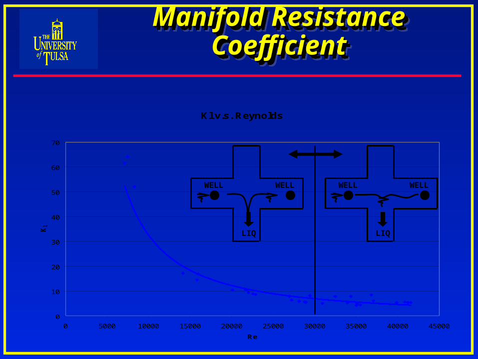
Kl v.s. Reynolds
0
10
20
30
40
50
60
70
0 5000 10000 15000 20000 25000 30000 35000 40000 45000
Re
Kl
LIQ
WELLWELL
LIQ
WELLWELL
Manifold Resistance CoefficientManifold Resistance CoefficientManifold Resistance CoefficientManifold Resistance Coefficient
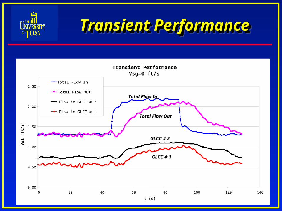
Transient PerformanceTransient PerformanceTransient PerformanceTransient Performance
Transient PerformanceVsg=0 ft/s
0.00
0.50
1.00
1.50
2.00
2.50
0 20 40 60 80 100 120 140
t (s)
Vsl
(ft
/s)
Total Flow In
Total Flow Out
Flow in GLCC # 2
Flow in GLCC # 1
Total Flow InTotal Flow In
Total Flow OutTotal Flow Out
GLCC # 1GLCC # 1
GLCC # 2GLCC # 2

Transient PerformanceVsg=6.7 ft/s
0.00
0.50
1.00
1.50
2.00
2.50
0 50 100 150 200
t (s)
Vs
l (f
t/s
)
Total Flow In
Total Flow Out
Flow in GLCC # 2
Flow in GLCC # 1
Transient PerformanceTransient PerformanceTransient PerformanceTransient Performance
Total Flow InTotal Flow In
Total Flow OutTotal Flow Out
GLCC # 1GLCC # 1
GLCC # 2GLCC # 2

Manifold DesignManifold DesignManifold DesignManifold Design
Diameter
Manifold
Outlets
Inlet Wells Arrangement
Design Example

Manifold SizingManifold SizingManifold SizingManifold Sizing
The Design Code is based on simplified Kelvin-Helmholtz stability analysis
The stabilizing gravity force acting on the wave is,
gCoshh GLGG '
The pressure suction force causing wave growth is given by,
22''
2
1GGG vvPP

Manifold SizingManifold SizingManifold SizingManifold Sizing
Two criteria were evaluated to determine the manifold
diameter
Criterion 1: Diameter is calculated only considering
each section separately

Manifold SizingManifold SizingManifold SizingManifold Sizing
Criterion 2: Diameter is calculated considering the
effect of one well on its neighbors

Outlets SizingOutlets SizingOutlets SizingOutlets Sizing
Liquid Outlets
1
2
lL K
ghV
L
L
V
QA
Gas Outlets
1
2
2
VKg
P
G
G
V
QA

Wells ArrangementWells ArrangementWells ArrangementWells Arrangement
Based on experimental results, two modifications were
proposed to Avila-Gomez model
Proposal 1: Make well arrangement based on ratio
Qmixture/Ql
Proposal 2: Make well arrangement locating wells with
high gas flow rates in middle section of manifold.

Design ExampleDesign ExampleDesign ExampleDesign Example
Example of manifold with seven wells connected

Design CodeDesign CodeDesign CodeDesign Code
Auto-arrangement considering proposal # 1

Design CodeDesign CodeDesign CodeDesign Code
Auto-arrangement considering proposal # 2
Future WorkFuture WorkFuture WorkFuture Work
Design Code

Safety TipSafety TipSafety TipSafety Tip

QUESTIONSQUESTIONSQUESTIONSQUESTIONS
?