turbopro™ pro-t™ insertion turbine volumetric and mass flow
TRANSCRIPT
101 CAL-BENCH Instruction Manual Chapter 1 Introduction
8/15/2011 1-1
VorTek Pro-T™ Model
Turbo-Pro™ Insertion Turbine
Volumetric and Mass Flow Meters
Document Number M-000-00020
Rev 08/2011
8475 W I-25 Frontage Rd Suite 300
Longmont, CO 80504 (303) 682-9999 (888) 386-7835 Fax (303) 682-4368
http://www.vortekinst.com

This flow meter is not intended for oxygen service. VorTek Instruments, LLC is not liable for any damage or personal injury, whatsoever, resulting from the use of VorTek Instruments insertion turbine flow meters for oxygen gas. If oxygen ser-vice is required please consult factory.
© COPYRIGHT VORTEK INSTRUMENTS 2011 No part of this publication may be copied or distributed, transmitted, transcribed, stored in a retrieval system, or translated into any human or computer language, in any form or by any means, electronic, mechanical, manual, or otherwise, or disclosed to third parties without the express written permission of VorTek Instruments. The information contained in this manual is subject to change without notice. TRADEMARKS Pro-T™ is a trademark of VorTek Instruments, LLC. Other product and company names listed in this manual are trademarks or trade names of their respective manufacturers.

Pro-T™ Multi-Variable Turbine Mass Flow Meters ........................... 1-1 Using this Manual ......................................................................... 1-2 Note and Safety Information ......................................................... 1-3 Receipt of System Components .................................................... 1-3 Technical Assistance ..................................................................... 1-3 How the Pro-T™ Turbine Mass Flow Meter Operates ........................ 1-4 Velocity Measurement .................................................................. 1-4 Flow Velocity Range ..................................................................... 1-4 Temperature Measurement ............................................................ 1-5 Pressure Measurement ................................................................... 1-5 Flow Meter Configuration ................................................................... 1-5 Multivariable Options ................................................................... 1-5 Line Size / Process Connections ................................................... 1-6 Flow Meter Electronics ................................................................. 1-6
Installation Overview ........................................................................... 2-1 Flow Meter Installation Requirements .......................................... 2-1 Unobstructed Flow Requirements ................................................. 2-2 Insertion Flow Meter Installation ........................................................ 2-3 Cold Tap Guidelines...................................................................... 2-4 Hot Tap Guidelines ....................................................................... 2-5 Flow Meter Insertion ........................................................................... 2-7 Installing Meters with a Compression Connection ....................... 2-8 Installing Meters with a Packing Gland Connection ................... 2-10 Installing Meters (Packing Gland), No Insertion Tool ................ 2-13 Display/Keypad Adjustment ....................................................... 2-15 Loop Power Flow Meter Wiring Connections ................................... 2-16 Input Power Connections ............................................................ 2-16 4-20 mA Output Connections ..................................................... 2-17 Pulse Output Connections ........................................................... 2-18 Frequency Output Connections ................................................... 2-19 Optional Backlight Connections ................................................. 2-19 Remote Electronics Wiring ......................................................... 2-20 High Power Flow Meter Wiring Connections ................................... 2-22 Input Power Connections ............................................................ 2-22 4-20 mA Output Connections ..................................................... 2-24 Frequency Output Connections ................................................... 2-25 Pulse Output Connections ........................................................... 2-26 Alarm Output Connections .......................................................... 2-28 Remote Electronics Wiring ......................................................... 2-29 Optional Input Electronics Wiring .............................................. 2-30 Optional Energy EMS RTD Input Wiring .................................. 2-30 Optional External 4-20 mA Input Wiring ................................... 2-31 Optional Contact Closure Input Wiring ...................................... 2-32
Flow Meter Display/Keypad ................................................................ 3-1 Start Up ................................................................................................ 3-2 Using the Setup Menus ........................................................................ 3-4 Programming the Flow Meter ....................................................... 3-5 Output Menu ................................................................................. 3-6 Display Menu ................................................................................ 3-8 Alarms Menu ................................................................................. 3-9 Totalizer #1 Menu ....................................................................... 3-10 Totalizer #2 Menu ....................................................................... 3-11
Energy Menu ....................................................................... 3-12 Fluid Menu .................................................................................. 3-13 Units Menu .................................................................................. 3-14 Time and Date Menu ................................................................... 3-15 Diagnostics Menu ........................................................................ 3-16 Calibration Menu ......................................................................... 3-17 Password Menu ........................................................................... 3-18
HART Communications ...................................................................... 4-1 Wiring ........................................................................................... 4-1 HART Commands with the DD Menu .......................................... 4-3 HART Commands with Generic DD Menu .................................. 4-8 MODBUS Communications .............................................................. 4-11 Wiring ......................................................................................... 4-11 Menu Items .................................................................................. 4-12 Register Definitions ..................................................................... 4-14
Hidden Diagnostics Menus .................................................................. 5-1 Level One Hidden Diagnostics Values ......................................... 5-3 Level Two Hidden Diagnostics Values ......................................... 5-4 Analog Output Calibration .................................................................. 5-7 Troubleshooting the Flow Meter ......................................................... 5-8 First Check Items .......................................................................... 5-8 Record Values ............................................................................... 5-8 Determine the Fault ............................................................................. 5-9 Symptom: Output at no Flow ........................................................ 5-9 Symptom: Erratic Output .............................................................. 5-9 Symptom: No Output .................................................................. 5-11 Symptom: Meter Displays Temperature Fault ............................ 5-12 Symptom: Meter Displays Pressure Fault ................................... 5-13 Electronics Assembly Replacement ................................................... 5-14 Returning Equipment to the Factory .................................................. 5-15

1-1. Insertion Turbine Multivariable Mass Flow Meters ............... 1-1 2-1. Recommended Pipe Length Required for Installation ............ 2-2 2-2. Hot Tap Sequence ................................................................... 2-6 2-3. Insertion Calculation (Compression Type) ............................. 2-8 2-4. Flow Meter with Compression Type Fitting ........................... 2-9 2-5. Insertion Calculation (Meters with Insertion Tool) .............. 2-10 2-6. Flow Meter with Permanent Insertion Tool .......................... 2-11 2-7. Flow Meter with Removable Insertion Tool ......................... 2-12 2-8. Insertion Calculation (Meters without Insertion Tool) ......... 2-13 2-9. Display/Keypad Viewing Adjustment .................................. 2-15 2-10. Loop Power Wiring Terminals ............................................. 2-16 2-11. DC Power Connections ......................................................... 2-16 2-12. Load Resistance Versus Input Voltage ................................. 2-17 2-13. Isolated Pulse Output Using External Power Supply ........... 2-18 2-14. Non-Isolated Pulse Output Using External Power Supply ... 2-18 2-15. Isolated Frequency Output Using External Power Supply ... 2-19 2-16. Non-Isolated Freq. Output Using External Power Supply .... 2-19 2-17. Backlight Using External Power Supply .............................. 2-19 2-18. Loop Power Volumetric Flowmeter Junction Box ............... 2-20 2-19. Loop Power Mass Flowmeter Junction Box ......................... 2-21 2-20. AC Wiring Terminals ........................................................... 2-22 2-21. AC Power Connections ......................................................... 2-22 2-22. DC Wiring Terminals ........................................................... 2-23 2-23. DC Power Connections ......................................................... 2-23 2-24. Load Resistance Versus Input Voltage ................................. 2-24 2-25. Isolated 4-20 Output Using External Power Supply ............. 2-24 2-26. Non-Isolated 4-20 Output Using Input Power Supply .......... 2-25 2-27. Isolated 4-20 Output Using Meter Power Supply (AC only) 2-25 2-28. Isolated Frequency Output Using External Power Supply ... 2-26 2-29. Non-Isolated Freq. Output Using Input Power Supply ......... 2-26 2-30. Isolated Freq. Output Using Meter Power Sup. (AC only) ... 2-26 2-31. Isolated Pulse Output Using External Power Supply ........... 2-27 2-32. Non-Isolated Pulse Output Using Input Power Supply ........ 2-27 2-33. Isolated Pulse Output Using Meter Power Sup. (AC only) .. 2-27 2-34. Isolated Alarm Output Using External Power Supply .......... 2-28 2-35 Non-Isolated Alarm Output Using Meter Power Supply ...... 2-28 2-36 Isolated Alarm Output Using Meter Power Sup. (AC only) 2-29 2-37 High Power Flow Meter Junction Box ................................ 2-29 2-38. Optional Energy EMS RTD Input Wiring ............................ 2-30 2-39. External 4-20 mA Input Wiring – External Power Supply ... 2-31 2-40. External 4-20 mA Input Wiring – DC Powered Meter ......... 2-31 2-41. External 4-20 mA Input Wiring – AC Powered Meter ......... 2-32 2-42. Optional External Contact Closure Input Wiring ................. 2-32 3-1. Flow Meter Display / Keypad…………………………….....3-1 4-1. Loop Powered Meter Wiring (HART) .................................... 4-1 4-2. DC Powered Meter Wiring (HART) ...................................... 4-2

4-3. AC Powered Meter Wiring (HART) ...................................... 4-2 4-4. RS-485 Wiring (MODBUS) ................................................... 4-7
1-1. Measurable Range .................................................................. 1-4 4-1. Byte Order (MODBUS) .......................................................... 4-9 4-2. Register Definitions (MODBUS) ......................................... 4-11


The VorTek Instruments’ Pro-T™ Insertion Turbine Flow Meters pro-vide a reliable solution for process flow measurement. From a single en-try point in the pipeline, Pro-T™ meters offer precise measurements of mass or volumetric flow rates.
Mass flow meters utilize three primary sensing elements: a rotating turbine velocity sensor, an RTD temperature sensor, and a solid state pressure sensor to measure the mass flow rate of gases, liquids, and steam. Meters are available as loop powered devices or with up to three 4-20 mA analog output signals for monitoring your choice of the six process variables (energy flow, mass flow, volumetric flow, temperature, pressure and fluid density). The Energy Monitoring option permits real-time calculation of energy consumption for a facility or process.
The primary sensing element of a volumetric flow meter is a rotating tur-bine velocity sensor. Meters are loop powered. The analog 4-20 mA output signal offers your choice of volumetric or mass flow rate. Mass flow rate is based on a constant value for fluid density stored in the in-strument’s memory.
Both the mass and volumetric flow meters can be ordered with a local keypad/display which provides instantaneous flow rate, total, and process parameters in engineering units. A pulse output signal for remote totali-zation and MODBUS or HART communications are also available. Pro-T™ digital electronics allows for easy reconfiguration for most gases, liquids and steam. The VorTek Model Pro-T™ Meters’ simple installa-tion combines with an easy-to-use interface that provides quick set up, long term reliability and accurate mass flow measurement over a wide range of flows, pressures and temperatures.
This manual provides information needed to install and operate the Pro-T™ Insertion Turbine Flow Meters. • Chapter 1 includes the introduction and product description
• Chapter 2 provides information needed for installation
• Chapter 3 describes system operation and programming
• Chapter 4 provides information on HART and MODBUS protocols
• Chapter 5 covers troubleshooting and repair Appendix A - Product Specifications, Appendix B – Flow Meter Calcu-lations, Appendix C – Glossary of Terms
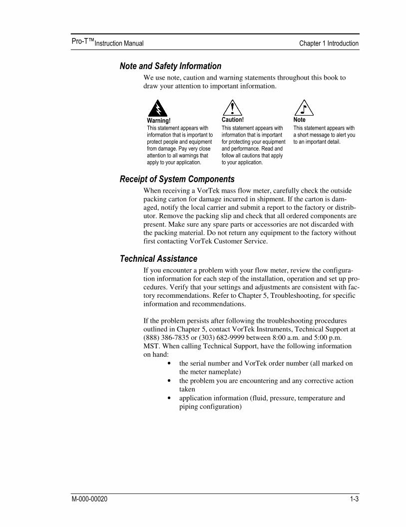
We use note, caution and warning statements throughout this book to draw your attention to important information.
When receiving a VorTek mass flow meter, carefully check the outside packing carton for damage incurred in shipment. If the carton is dam-aged, notify the local carrier and submit a report to the factory or distrib-utor. Remove the packing slip and check that all ordered components are present. Make sure any spare parts or accessories are not discarded with the packing material. Do not return any equipment to the factory without first contacting VorTek Customer Service.
If you encounter a problem with your flow meter, review the configura-tion information for each step of the installation, operation and set up pro-cedures. Verify that your settings and adjustments are consistent with fac-tory recommendations. Refer to Chapter 5, Troubleshooting, for specific information and recommendations.
If the problem persists after following the troubleshooting procedures outlined in Chapter 5, contact VorTek Instruments, Technical Support at (888) 386-7835 or (303) 682-9999 between 8:00 a.m. and 5:00 p.m. MST. When calling Technical Support, have the following information on hand:
• the serial number and VorTek order number (all marked on the meter nameplate)
• the problem you are encountering and any corrective action taken
• application information (fluid, pressure, temperature and piping configuration)
VorTek Model Pro-T™ Multivariable Insertion Turbine Mass Flow Me-ters are designed to monitor mass flow rate by directly measuring three variables–fluid velocity, temperature and pressure. The built-in flow computer calculates the mass flow rate and volumetric flow rate based on these three direct measurements. To measure fluid velocity, the flow me-ter incorporates a rotating turbine in the flow stream. The rotation is converted into an electrical output which is proportional to fluid velocity. Temperature is measured using a platinum resistance temperature detec-tor (PRTD) and pressure measurement is achieved using a solid-state pressure transducer.
Fluid passing through the turbine causes its rotor to spin. The rotor is fabricated from 17-4PH stainless steel which is slightly magnetic, and is positioned in close proximity to a passive magnetic pickup coil. As each blade rotates by the pickup coil, a small sinusoidal voltage is generated. This sinusoidal voltage is then amplified, fil-tered, and shaped by the measurement electronics. The frequency of the signal is proportional to the flowing velocity.
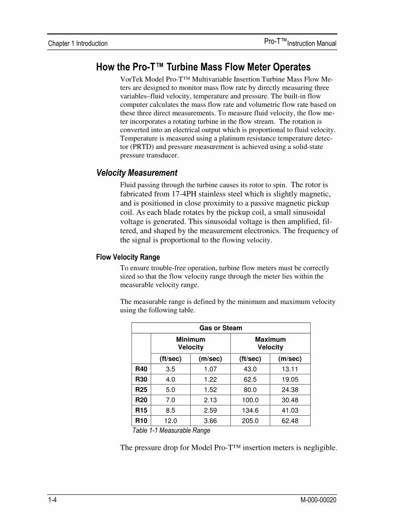
To ensure trouble-free operation, turbine flow meters must be correctly sized so that the flow velocity range through the meter lies within the measurable velocity range. The measurable range is defined by the minimum and maximum velocity using the following table.
Gas or Steam
Minimum Velocity
Maximum Velocity
(ft/sec) (m/sec) (ft/sec) (m/sec)
R40 3.5 1.07 43.0 13.11
R30 4.0 1.22 62.5 19.05
R25 5.0 1.52 80.0 24.38
R20 7.0 2.13 100.0 30.48
R15 8.5 2.59 134.6 41.03
R10 12.0 3.66 205.0 62.48
The pressure drop for Model Pro-T™ insertion meters is negligible.

Pro-T Flow Meters use a 1000 ohm platinum resistance temperature detec-tor (PRTD) to measure fluid temperature.
Pro-T Flow Meters incorporate a solid-state pressure transducer isolated by a 316L stainless steel diaphragm. The transducer itself is micro-machined silicon, fabricated using integrated circuit processing technol-ogy. A nine-point pressure/temperature calibration is performed on every sensor. Digital compensation allows these transducers to operate within a 0.3% of full scale accuracy band within the entire ambient temperature range of -40°F to 140°F (-40 to 60°C). Thermal isolation of the pressure transducer ensures the same accuracy across the allowable process fluid temperature range of -200°F to 750°F (-128 to 400°C).
The Pro-T™ Insertion Turbine Mass Flow Meter has a sensing head which contains the turbine rotor, temperature sensor, and pressure tap. The pressure sensor is located in the pressure transducer housing be-tween the stem and electronics housing. The meter is installed through a full port block valve and mounting adap-ter having a clear, cylindrical port diameter of 1.875” diameter. It can be installed during system downtime or using standard “Hot Tap” proce-dures. The meter directly monitors the velocity at a point in the cross-sectional area of a pipe, duct, or stack. The velocity at a point in the pipe varies as a function of the Reynolds number. When a fluid flows through a pipe, the velocity generated is not constant across the diameter. The fluid ve-locity varies across the diameter of the pipe creating a “Velocity Profile”. That is, velocities near the center of the pipe are faster than those nearer to the wall. In addition, the velocity profile varies in concert with flow rate from the lowest to the highest flows. Mathematical descriptions of this profile have been developed for over 100 years. By knowing the ve-locity profile and the flow rate at a single point, the average flow rate can be determined. The accuracy of the flow rate computation depends on adherence to the piping installation requirements given in Chapter 2. If adherence to those guidelines cannot be met, contact the factory for spe-cific installation advice.
The Pro-T™ model is available with the following options: V, volumetric flowmeter; VT, velocity and temperature sensors; VTP, velocity, temperature, and pressure sensors; VT-EM energy output op-tions; VTP-EM, energy options with pressure; VT-EP, external pressure transmitter input.
The Pro-T™ Insertion model can be used in line sizes 2 inch and greater and is built with a compression fitting or packing gland design using 2 inch NPT, or 2 inch flanged connections (ANSI 150, 300, 600, PN16, 40, or 64 class flanges). The packing gland design can be ordered with a permanent or removable retractor.
Pro-T™ Flow Meter electronics are available mounted directly to the flow meter, or remotely mounted. The electronics housing may be used indoors or outdoors, including wet environments. Available input power options are: DC loop powered (2-wire), DC powered, or AC powered. Three analog output signals are available for your choice of three of the six process variables: energy flow rate, mass flow rate, volumetric flow rate, temperature, pressure or fluid density. A pulse output signal for remote totalization and MODBUS or HART communications are also available.
Pro-T™ Flow Meters include a local 2 x 16 character LCD display housed within the enclosure. Local operation and reconfiguration is ac-complished using six pushbuttons operated via finger touch. For hazard-ous locations, the six buttons can be operated with the electronics enclo-sure sealed using a hand-held magnet, thereby not compromising the in-tegrity of the hazardous location certification. The electronics include nonvolatile memory that stores all configuration information. The nonvolatile memory allows the flow meter to function immediately upon power up, or after an interruption in power. All flowmeters are calibrated. The instrument is configured for the custom-er’s flow application.
VorTek’s Pro-T™ Insertion Turbine Flow Meter installations are simple and straightforward. After reviewing the installation requirements given below, see page 2-3 for Pro-T™ installation instructions. Wiring instruc-tions begin on page 2-16.
Before installing the flow meter, verify the installation site allows for these considerations:
1. Line pressure and temperature will not exceed the flow meter rating.
2. The location meets the required minimum number of pipe di-
ameters upstream and downstream of the sensor head as illu-strated in Figure 2-1.
3. Safe and convenient access with adequate overhead clear-
ance for maintenance purposes.
4. Verify that the cable entry into the instrument meets the specific standard required for hazardous area installations.
5. For remote installations, verify the supplied cable length is
sufficient to connect the flow meter sensor to the remote electronics.
Also, before installation check your flow system for anomalies such as:
• leaks
• valves or restrictions in the flow path that could create distur-bances in the flow profile that might cause unexpected flow rate indications
• avoid areas where high RF, EMI, or other electrical interference may be present. Devices such as VFD’s (variable frequency drives), large AC motors, etc.

2
Select an installation site that will minimize possible distortion in the flow profile. Valves, elbows, control valves and other piping components may cause flow disturbances. Check your specific piping condition against the examples shown below. In order to achieve accurate and repeatable per-formance install the flow meter using the recommended number of straight run pipe diameters upstream and downstream of the sensor. Note: For liquid applications in vertical pipes, avoid installing with flow in the downward direction because the pipe may not be full at all points. Choose to install the meter with flow in the upward direction if possible.
Minimum Required Upstream Diameters
Minimum Required Downstream Diameters
No Flow Conditioner
With Flow Conditioner
No Flow Conditioner
With Flow Conditioner
Example A A C C´ B B 1 10 D 5 D 3 D 2 D 5 D 4 D 2 15 D 11 D 6 D 5 D 5 D 4 D 3 30 D 12 D 7 D 5 D 5 D 4 D 4 10 D 8 D 5 D 3 D 5 D 4 D 5 30 D 13 D 7 D 6 D 5 D 4 D
D = Internal diameter of channel. N/A = Not applicable

Prepare the pipeline for installation using either a cold tap or hot tap me-thod described on the following pages. Refer to a standard code for all pipe tapping operations. The following tapping instructions are general in nature and intended for guideline purposes only. Before installing the me-ter, review the mounting position and isolation value requirements given below.
Allow clearance between the electronics enclosure top and any other ob-struction when the meter is fully retracted.
An isolation valve is available as an option with Pro-T™ meters. If you supply the isolation valve, it must meet the following requirements:
1. A minimum valve
bore diameter of 1.875 inches is re-quired, and the valve’s body size should be two inches. Normally, gate valves are used.
2. Verify that the
valve’s body and flange rating are within the flow meter’s maximum operating pressure and tempera-ture.
3. Choose an isolation valve with at least two inches existing between
the flange face and the gate portion of the valve. This ensures that the flow meter’s sensor head will not interfere with the operation of the isolation valve.
1.875-inch min. valve bore
2-inch min.
2-inch valve size
Isolation Valve Requirements
4
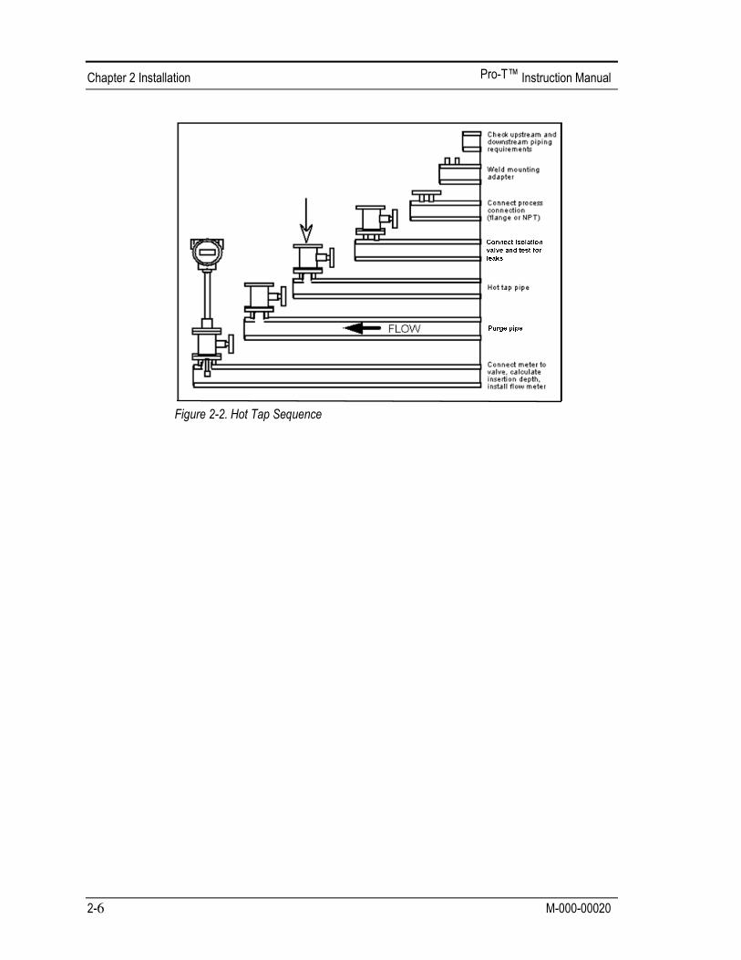
Refer to a standard code for all pipe tapping operations. The following tapping instructions are general in nature and intended for guideline pur-poses only. 1. Turn off the flow of process gas, liquid or steam. Verify that the line
is not pressurized. 2. Confirm that the installation site meets the minimum upstream and
downstream pipe diameter requirements. See Figure 2-1. 3. Use a cutting torch or sharp cutting tool to tap into the pipe. The pipe
opening must be at least 1.875 inches in diameter. (Do not attempt to insert the sensor probe through a smaller hole.)
4. Remove all burrs from the tap. Rough edges may cause flow profile
distortions that could affect flow meter accuracy. Also, obstructions could damage the sensor assembly when inserting into the pipe.
5. After cutting, measure the thickness of the cut-out and record this
number for calculating the insertion depth. 6. Weld the flow meter pipe connection
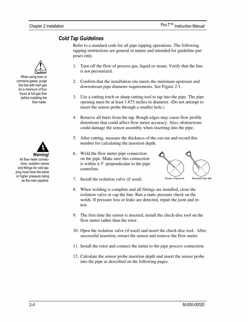
on the pipe. Make sure this connection is within ± 5° perpendicular to the pipe centerline.
7. Install the isolation valve (if used). 8. When welding is complete and all fittings are installed, close the
isolation valve or cap the line. Run a static pressure check on the welds. If pressure loss or leaks are detected, repair the joint and re-test.
9. The first time the sensor is inserted, install the check-disc tool on the
flow meter rather than the rotor. 10. Open the isolation valve (if used) and insert the check-disc tool. After
successful insertion, retract the sensor and remove the flow meter.
11. Install the rotor and connect the meter to the pipe process connection. 12. Calculate the sensor probe insertion depth and insert the sensor probe
into the pipe as described on the following pages.
Refer to a standard code for all pipe tapping operations. The following tapping instructions are general in nature and intended for guideline pur-poses only. 1. Confirm that the installation site meets the minimum upstream and
downstream pipe diameter requirements. 2. Weld a two inch mounting adapter on the pipe. Make sure the mount-
ing adapter is within ± 5° perpendicular to the pipe centerline (see previous page). The pipe opening must be at least 1.875 inches in di-ameter.
3. Connect a two inch process connection on the mounting adapter. 4. Connect an isolation valve on the process connection. The valve’s full
open bore must be at least 1.875 inches in diameter. 5. Run a static pressure check on the welds. If pressure loss or leaks are
detected, repair the joint and re-test. 6. Connect the hot tapping equipment to the isolation valve, open the
isolation valve and drill at least a 1.875 inch diameter hole.
7. Retract the drill, close the isolation valve, and remove the hot tapping equipment.
8. The first time the sensor is installed, install the check-disc tool on the flow meter rather than the rotor.
9. Open the isolation valve and insert the check-disc tool. After success-ful insertion, retract the sensor, close the isolation valve and remove the flow meter.
10. Install the rotor, connect the flow meter to the isolation valve and open the isolation valve.
11. Calculate the sensor probe insertion depth and insert the sensor probe into the pipe as described on the following pages.
6

The sensor head must be properly positioned in the pipe. For this reason, it is important that insertion length calculations are carefully followed. A sensor probe inserted at the wrong depth in the pipe will result in inaccu-rate readings. Insertion flow meters are applicable to pipes 2 inches and larger. For pipe sizes 10 inches and smaller, the centerline of the meter’s sensing head is located at the pipe’s centerline. For pipe sizes larger than 10 inches, the centerline of the sensing head is located 5 inches from the in-side wall of the pipe.
Insertion flow meters are available in three probe lengths: Standard Probe configuration is used with most flow meter process connections. The length, S, of the stem is 28.67 inches. Compact Probe configuration is used with compression fitting process connections. The length, S, of the stem is 12.3 inches.
12-Inch Extended Probe configuration is used with exceptionally lengthy flow meter process connections. The length, S, of the stem is 40.67 inch-es.
Depending on your flow meter’s process connection, use the applicable insertion length formula and installation procedure as follows:
• Flow meters with a compression type connection (NPT or flanged)
follow the instructions beginning on page 2-8. • Flow meters with a packing gland type connection (NPT or flanged)
configured with an insertion tool, follow the instructions beginning on page 2-10.
• Flow meters with a packing gland type connection (NPT or flanged) without an insertion tool, follow the instructions beginning on page 2-13.

8
Use the following formula to determine insertion length for flow meters (NPT and flanged) with a compression process connection. The installa-tion procedure is given on the next page.
Insertion Length Formula I = S – F – R – t
Where:
I = Insertion length. S = Stem length – the distance from the center of the sensor head to the base of the
enclosure adapter (S = 28.67 inches for standard probes; S = 12.3inches for compact; S = 40.67 inches for 12-inch extended).
F = Distance from the raised face of the flange or top of NPT stem housing to the outside of the pipe wall.
R = Pipe inside diameter ÷ 2 for pipes ten inches and smaller. R = Five inches for pipe diameters larger than ten inches. t = Thickness of the pipe wall. (Measure the disk cut-out from the tapping proce-
dure or check a piping handbook for thickness.)
To install a Pro-T™ meter with a standard probe (S = 28.67 inches) into a 14 inch schedule 40 pipe, the following measurements are taken:
F=3 inches R=5 inches t=0.438 inches
The insertion length for this example is 20.23 inches. Insert the stem through the fitting until an insertion length of 20.23 inches is measured with a ruler. *All dimensions are in inches
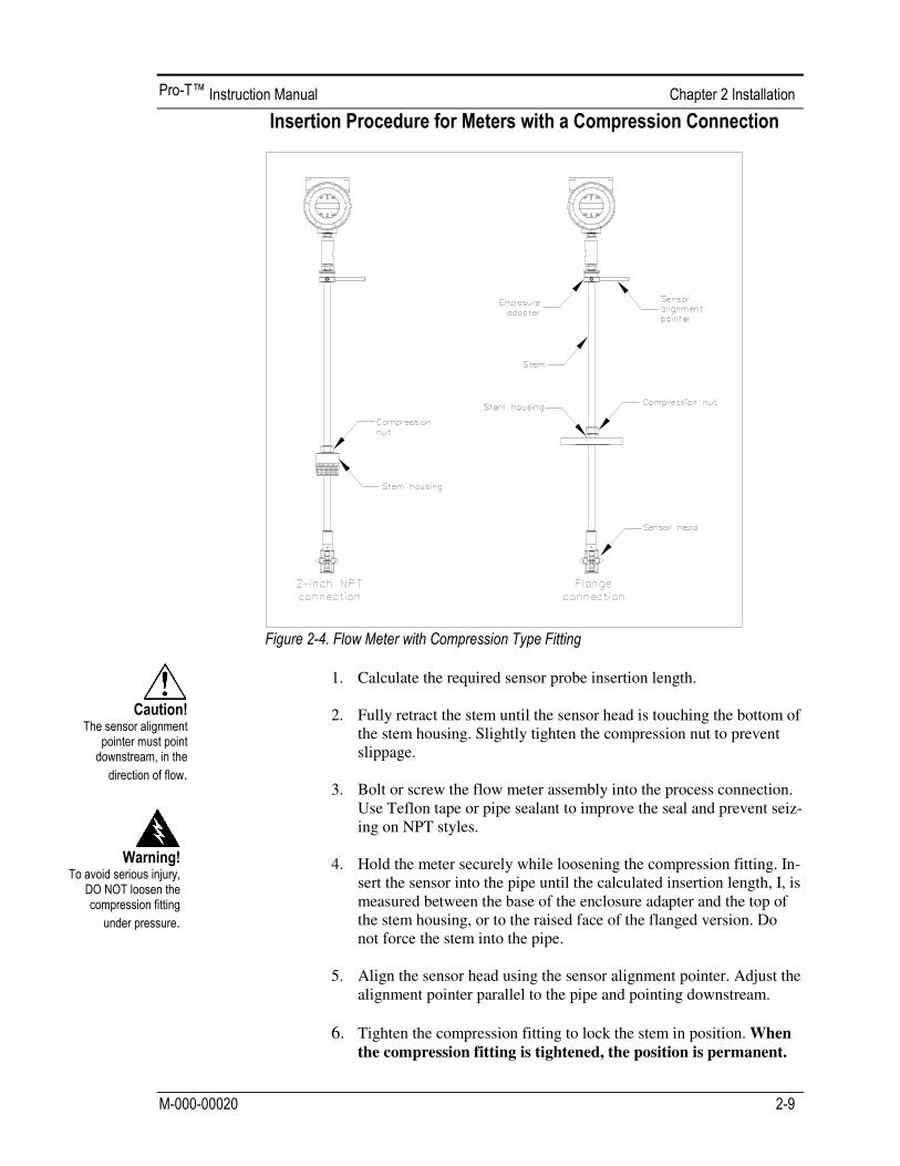
1. Calculate the required sensor probe insertion length.
2. Fully retract the stem until the sensor head is touching the bottom of
the stem housing. Slightly tighten the compression nut to prevent slippage.
3. Bolt or screw the flow meter assembly into the process connection.
Use Teflon tape or pipe sealant to improve the seal and prevent seiz-ing on NPT styles.
4. Hold the meter securely while loosening the compression fitting. In-
sert the sensor into the pipe until the calculated insertion length, I, is measured between the base of the enclosure adapter and the top of the stem housing, or to the raised face of the flanged version. Do not force the stem into the pipe.
5. Align the sensor head using the sensor alignment pointer. Adjust the
alignment pointer parallel to the pipe and pointing downstream.
6. Tighten the compression fitting to lock the stem in position. When the compression fitting is tightened, the position is permanent.
10
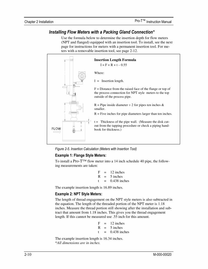
Use the formula below to determine the insertion depth for flow meters (NPT and flanged) equipped with an insertion tool. To install, see the next page for instructions for meters with a permanent insertion tool. For me-ters with a removable insertion tool, see page 2-12.
Insertion Length Formula
I = F + R + t – 0.55
Where:
I = Insertion length.
F = Distance from the raised face of the flange or top of the process connection for NPT style meters to the top outside of the process pipe.
R = Pipe inside diameter ÷ 2 for pipes ten inches & smaller.
R = Five inches for pipe diameters larger than ten inches.
t = Thickness of the pipe wall. (Measure the disk cut-out from the tapping procedure or check a piping hand-book for thickness.)
To install a Pro-T™ flow meter into a 14 inch schedule 40 pipe, the follow-ing measurements are taken:
F = 12 inches R = 5 inches t = 0.438 inches
The example insertion length is 16.89 inches.
The length of thread engagement on the NPT style meters is also subtracted in the equation. The length of the threaded portion of the NPT meter is 1.18 inches. Measure the thread portion still showing after the installation and sub-tract that amount from 1.18 inches. This gives you the thread engagement length. If this cannot be measured use .55 inch for this amount.
F = 12 inches R = 5 inches t = 0.438 inches
The example insertion length is 16.34 inches. *All dimensions are in inches.

1. Calculate the required sensor probe insertion length (see previous
page). Measure from the depth marker arrow down the stanchion and scribe a mark at the calculated insertion depth.
2. Fully retract the flow meter until the sensor head is touching the bot-
tom of the stem housing. Attach the meter assembly to the two inch full-port isolation valve, if used. Use Teflon tape or pipe sealant to improve seal and prevent seizing on NPT style.
3. Loosen the two packing gland nuts on the stem housing of the meter.
Loosen the stem lock bolt adjacent to the sensor alignment pointer. Align the sensor head using the sensor alignment pointer. Adjust the alignment pointer parallel to the pipe and pointing downstream. Tighten the stem lock bolt to secure the sensor position.
4. Slowly open the isolation valve to the full open position. If necessary,
slightly tighten the two packing gland nuts to reduce the leakage around the stem.
5. Turn the insertion tool handle clockwise to insert the sensor head into
the pipe. Continue until the top of the upper retractor bracket aligns with the insertion length position scribed on the stanchion. Do not force the stem into the pipe.
6. Tighten the packing gland nuts to stop leakage around the stem. Do not torque over 20 ft-lb.

12
1. Calculate the required sensor probe insertion length. Measure from
the depth marker arrow down the stanchion and scribe a mark at the calculated insertion depth.
2. Fully retract the flow meter until the sensor head is touching the bot-
tom of the stem housing. Attach the meter assembly to the two inch full-port isolation valve, if used. Use Teflon tape or pipe sealant to improve seal and prevent seizing on NPT style.
3. Remove the two top stem clamp nuts and loosen two stem clamp
bolts. Slide the stem clamp away to expose the packing gland nuts. 4. Loosen the two packing gland nuts. Loosen the stem lock bolt adja-
cent to the sensor alignment pointer. Align the sensor head using the sensor alignment pointer. Adjust the alignment pointer parallel to the pipe and pointing downstream. Tighten the stem lock bolt to secure the sensor position.
5. Slowly open the isolation valve to the full open position. If necessary,
slightly tighten the two packing gland nuts to reduce the leakage around the stem.
6. Turn the insertion tool handle clockwise to insert the stem into the
pipe. Continue until the top of the upper retractor bracket lines up with the insertion length mark scribed on the stanchion. Do not force the stem into the pipe.
7. Tighten the packing gland nuts to stop leakage around the stem. Do not torque over 20 ft-lbs.
8. Slide the stem clamp back into position. Torque stem clamp bolts to 15
ft-lbs. Replace the stem clamp nuts and torque to 10-15 ft-lbs.
9. To separate the insertion tool from the flow meter, remove four socket head cap bolts securing the upper and lower retractor brackets. Remove the insertion tool.
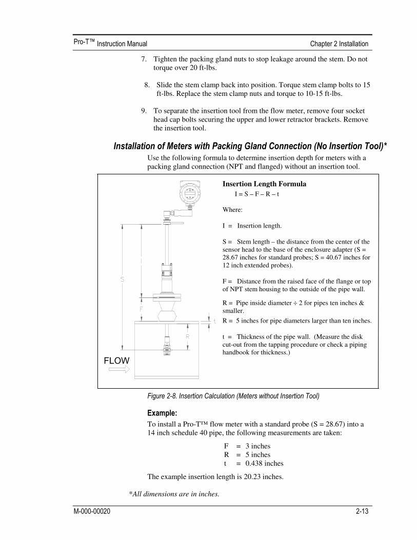
Use the following formula to determine insertion depth for meters with a packing gland connection (NPT and flanged) without an insertion tool.
Insertion Length Formula
I = S – F – R – t Where:
I = Insertion length.
S = Stem length – the distance from the center of the sensor head to the base of the enclosure adapter (S = 28.67 inches for standard probes; S = 40.67 inches for 12 inch extended probes).
F = Distance from the raised face of the flange or top of NPT stem housing to the outside of the pipe wall.
R = Pipe inside diameter ÷ 2 for pipes ten inches & smaller.
R = 5 inches for pipe diameters larger than ten inches.
t = Thickness of the pipe wall. (Measure the disk cut-out from the tapping procedure or check a piping handbook for thickness.)
To install a Pro-T™ flow meter with a standard probe (S = 28.67) into a 14 inch schedule 40 pipe, the following measurements are taken:
F = 3 inches R = 5 inches t = 0.438 inches
The example insertion length is 20.23 inches.
*All dimensions are in inches.
!"#$

14
1. Calculate the required sensor probe insertion length. 2. Fully retract the stem until the sensor head is touching the bottom of the
stem housing. Remove the two top stem clamp nuts and loosen two stem clamp bolts. Slide the stem clamp away to expose the packing gland nuts. Loosen the two packing gland nuts.
3. Align the sensor head using the sensor alignment pointer. Adjust the
alignment pointer parallel to the pipe and pointing downstream. 4. Insert the sensor head into the pipe until insertion length, I, is
achieved. Do not force the stem into the pipe. 5. Tighten the packing gland nuts to stop leakage around the stem. Do
not torque over 20 ft-lbs. 6. Slide the stem clamp back into position. Torque stem clamp bolts to
15 ft-lbs. Replace the stem clamp nuts and torque to 10-15 ft-lbs.
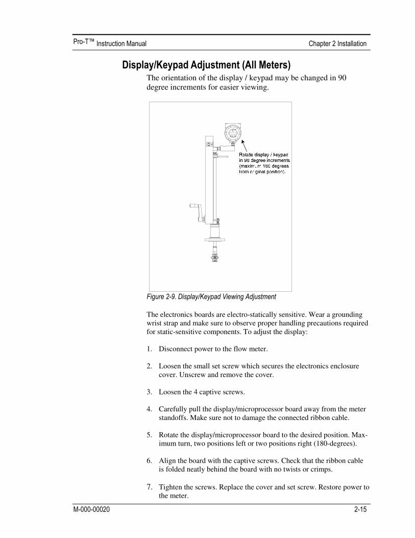
The orientation of the display / keypad may be changed in 90 degree increments for easier viewing.
The electronics boards are electro-statically sensitive. Wear a grounding wrist strap and make sure to observe proper handling precautions required for static-sensitive components. To adjust the display: 1. Disconnect power to the flow meter. 2. Loosen the small set screw which secures the electronics enclosure
cover. Unscrew and remove the cover. 3. Loosen the 4 captive screws. 4. Carefully pull the display/microprocessor board away from the meter
standoffs. Make sure not to damage the connected ribbon cable. 5. Rotate the display/microprocessor board to the desired position. Max-
imum turn, two positions left or two positions right (180-degrees). 6. Align the board with the captive screws. Check that the ribbon cable
is folded neatly behind the board with no twists or crimps.
7. Tighten the screws. Replace the cover and set screw. Restore power to the meter.
16
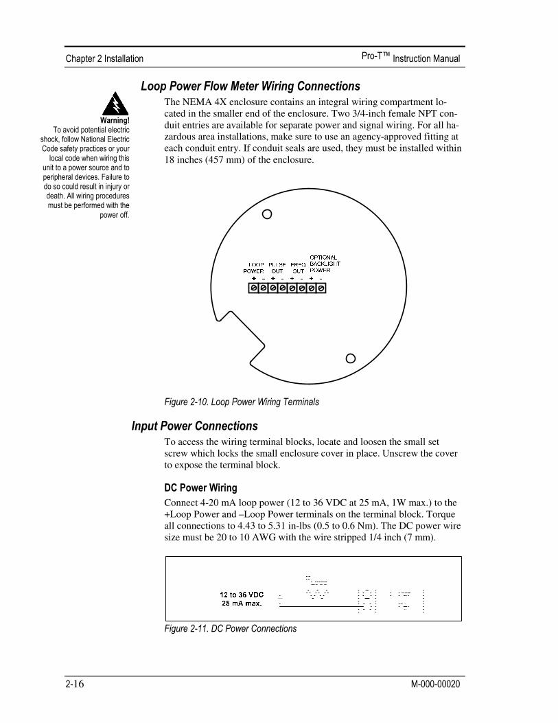
The NEMA 4X enclosure contains an integral wiring compartment lo-cated in the smaller end of the enclosure. Two 3/4-inch female NPT con-duit entries are available for separate power and signal wiring. For all ha-zardous area installations, make sure to use an agency-approved fitting at each conduit entry. If conduit seals are used, they must be installed within 18 inches (457 mm) of the enclosure.
To access the wiring terminal blocks, locate and loosen the small set screw which locks the small enclosure cover in place. Unscrew the cover to expose the terminal block.
Connect 4-20 mA loop power (12 to 36 VDC at 25 mA, 1W max.) to the +Loop Power and –Loop Power terminals on the terminal block. Torque all connections to 4.43 to 5.31 in-lbs (0.5 to 0.6 Nm). The DC power wire size must be 20 to 10 AWG with the wire stripped 1/4 inch (7 mm).
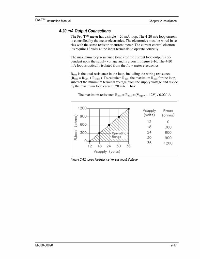
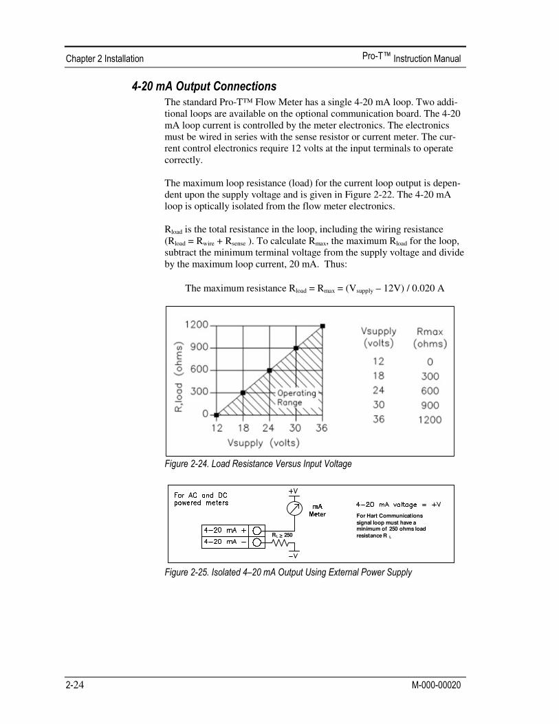
The Pro-T™ meter has a single 4-20 mA loop. The 4-20 mA loop current is controlled by the meter electronics. The electronics must be wired in se-ries with the sense resistor or current meter. The current control electron-ics require 12 volts at the input terminals to operate correctly. The maximum loop resistance (load) for the current loop output is de-pendent upon the supply voltage and is given in Figure 2-16. The 4-20 mA loop is optically isolated from the flow meter electronics. Rload is the total resistance in the loop, including the wiring resistance (Rload = Rwire + Rsense ). To calculate Rmax, the maximum Rload for the loop, subtract the minimum terminal voltage from the supply voltage and divide by the maximum loop current, 20 mA. Thus:
The maximum resistance Rload = Rmax = (Vsupply – 12V) / 0.020 A

18
The pulse output is used for a remote counter. When the preset volume or mass (defined in the totalizer settings, see page 3-10) has passed the me-ter, the output provides a 50 millisecond square pulse. The pulse output requires a separate 5 to 36 VDC power supply. The pulse output optical relay is a normally-open single-pole relay. The relay has a nominal 200 volt/160 ohm rating. This means that it has a nominal on-resistance of 160 ohms, and the largest voltage that it can withstand across the output terminals is 200 volts. However, there are current and power specifications that must be observed. The relay can conduct a cur-rent up to 40 mA and can dissipate up to 320 mW. The relay output is iso-lated from the meter electronics and power supply.
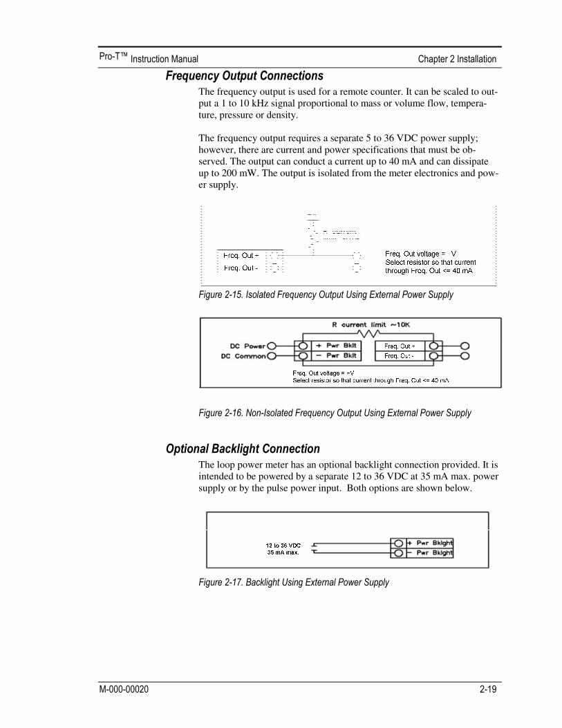
The frequency output is used for a remote counter. It can be scaled to out-put a 1 to 10 kHz signal proportional to mass or volume flow, tempera-ture, pressure or density. The frequency output requires a separate 5 to 36 VDC power supply; however, there are current and power specifications that must be ob-served. The output can conduct a current up to 40 mA and can dissipate up to 200 mW. The output is isolated from the meter electronics and pow-er supply.
The loop power meter has an optional backlight connection provided. It is intended to be powered by a separate 12 to 36 VDC at 35 mA max. power supply or by the pulse power input. Both options are shown below.

20
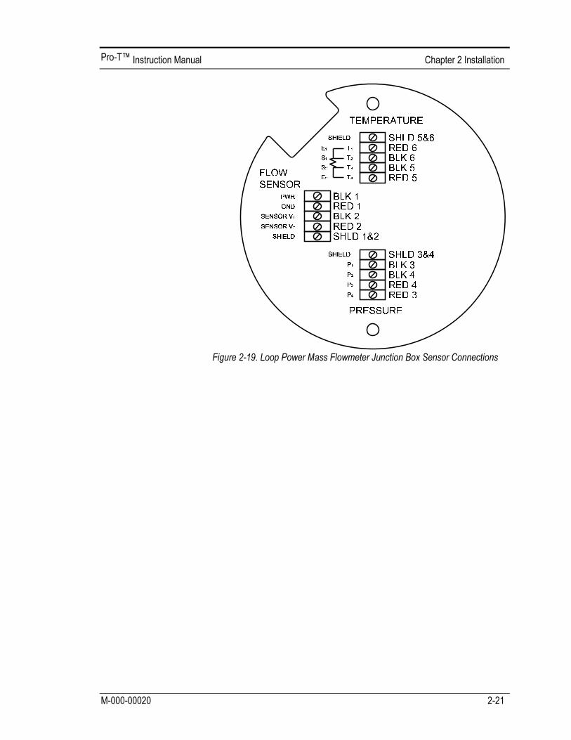
The remote electronics enclosure should be mounted in a convenient, easy to reach location. For hazardous location installations, make sure to ob-serve agency requirements for installation. Allow some slack in the inter-face cable between the junction box and the remote electronics enclosure. To prevent damage to the wiring connections, do not put stress on the terminations at any time. The meter is shipped with temporary strain relief glands at each end of the cable. Disconnect the cable from the meter’s terminal block inside the junction box–not at the remote electronics enclosure. Remove both glands and install appropriate conduit entry glands and conduit. When installa-tion is complete, re-connect each labeled wire to the corresponding ter-minal position on the junction box terminal block. Make sure to connect each wire pair’s shield. Note: incorrect connection will cause the meter to malfunction.
Note: Numeric code in junction box label matches wire labels.

22
The NEMA 4X enclosure contains an integral wiring compartment lo-cated in the smaller end of the enclosure. Two 3/4-inch female NPT con-duit entries are available for separate power and signal wiring. For all ha-zardous area installations, make sure to use an agency-approved fitting at each conduit entry. If conduit seals are used, they must be installed within 18 inches (457 mm) of the enclosure.
To access the wiring terminal blocks, locate and loosen the small set screw which locks the small enclosure cover in place. Unscrew the cover to expose the terminal block.
The AC power wire size must be 20 to 10 AWG with the wire stripped 1/4 inch (7 mm). The wire insulation temperature must meet or exceed 85°C (185°F). Connect 100 to 240 VAC (5 W maximum) to the Hot and Neutral terminals on the terminal block. Connect the ground wire to the safety ground lug ( ). Torque all connections to 4.43 to 5.31 in-lbs (0.5 to 0.6 Nm). Use a separate conduit entry for signal lines to reduce the pos-sibility of AC noise interference.
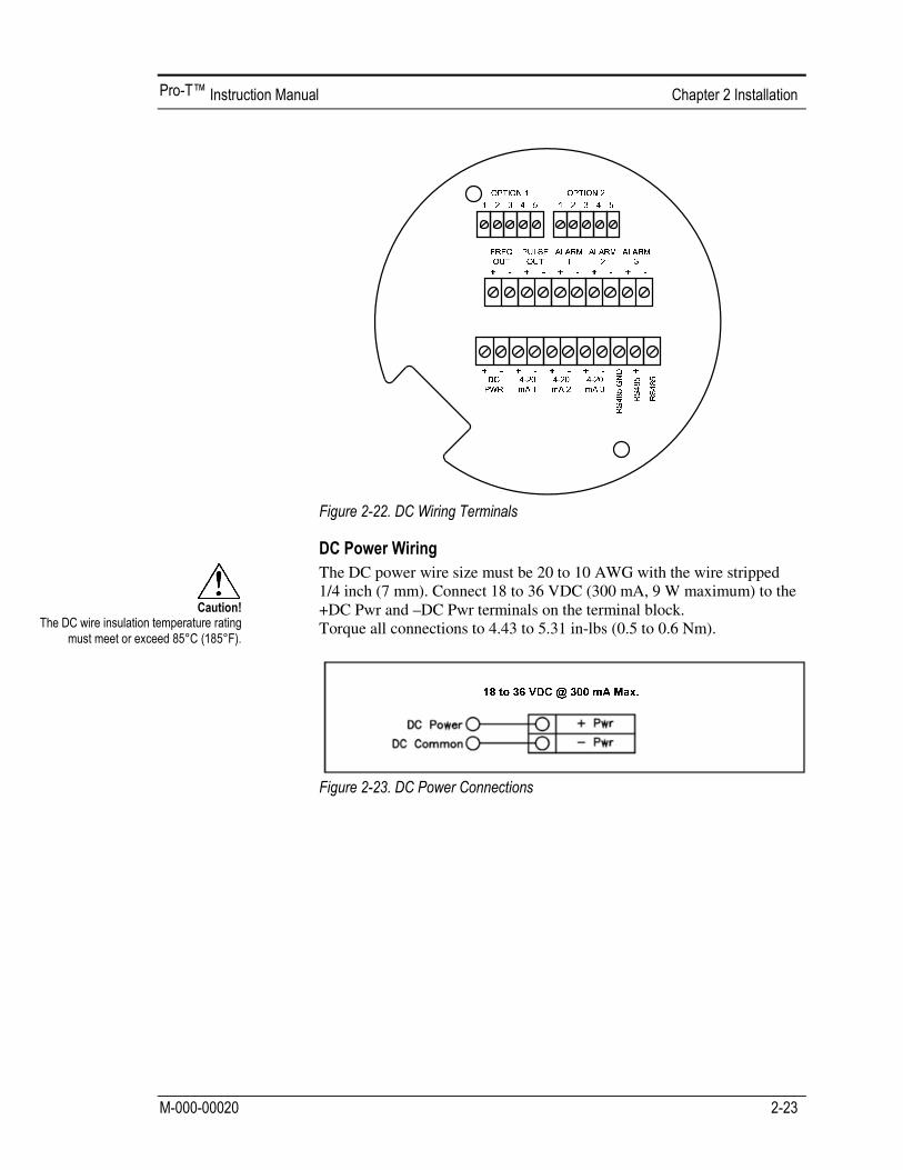
The DC power wire size must be 20 to 10 AWG with the wire stripped 1/4 inch (7 mm). Connect 18 to 36 VDC (300 mA, 9 W maximum) to the +DC Pwr and –DC Pwr terminals on the terminal block. Torque all connections to 4.43 to 5.31 in-lbs (0.5 to 0.6 Nm).
24
The standard Pro-T™ Flow Meter has a single 4-20 mA loop. Two addi-tional loops are available on the optional communication board. The 4-20 mA loop current is controlled by the meter electronics. The electronics must be wired in series with the sense resistor or current meter. The cur-rent control electronics require 12 volts at the input terminals to operate correctly. The maximum loop resistance (load) for the current loop output is depen-dent upon the supply voltage and is given in Figure 2-22. The 4-20 mA loop is optically isolated from the flow meter electronics. Rload is the total resistance in the loop, including the wiring resistance (Rload = Rwire + Rsense ). To calculate Rmax, the maximum Rload for the loop, subtract the minimum terminal voltage from the supply voltage and divide by the maximum loop current, 20 mA. Thus:
The maximum resistance Rload = Rmax = (Vsupply – 12V) / 0.020 A
For Hart Communications signal loop must have a minimum of 250 ohms load resistance R LRL > 250
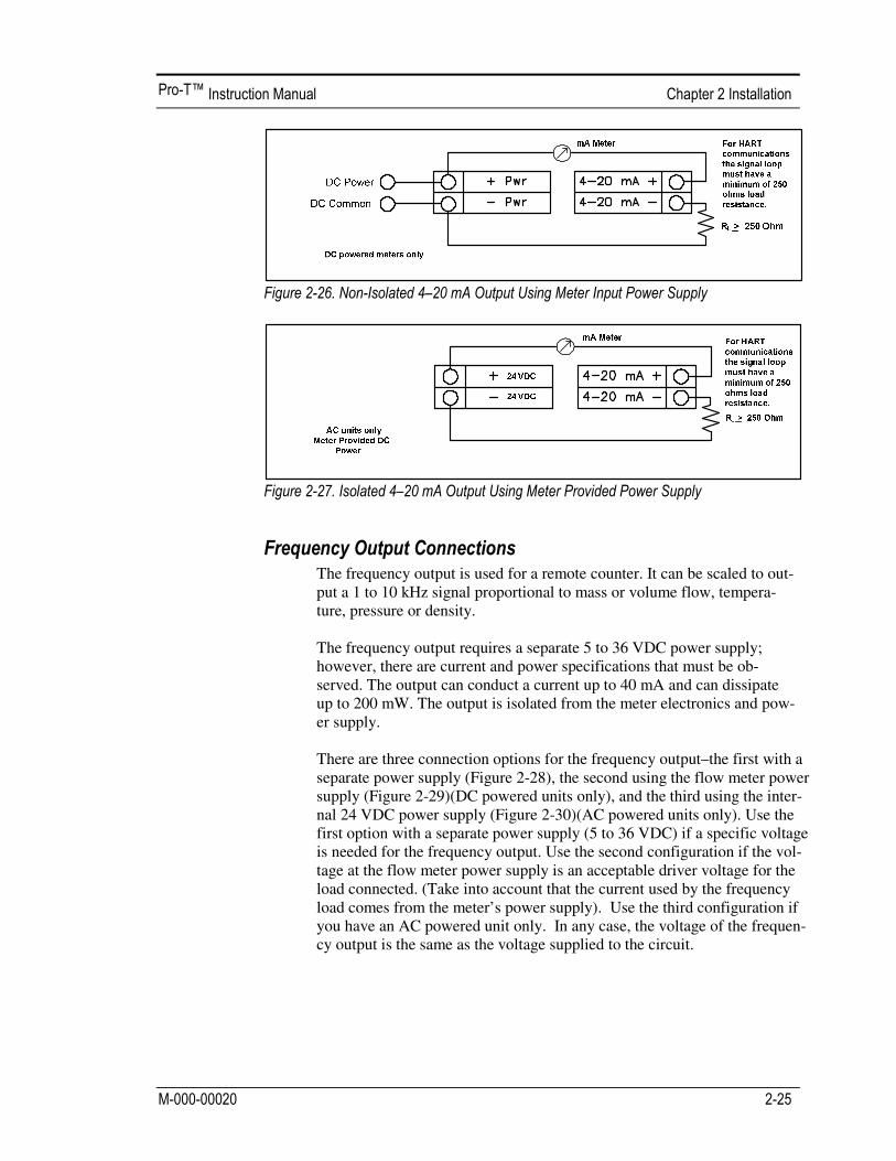
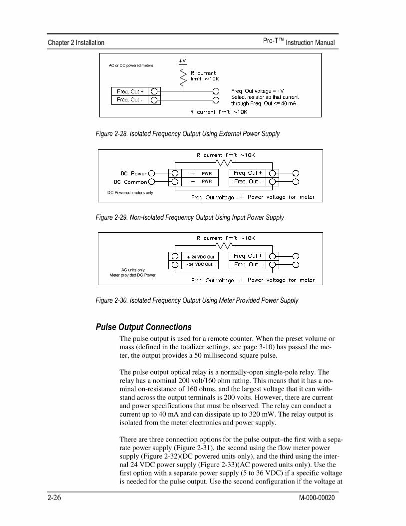
The frequency output is used for a remote counter. It can be scaled to out-put a 1 to 10 kHz signal proportional to mass or volume flow, tempera-ture, pressure or density. The frequency output requires a separate 5 to 36 VDC power supply; however, there are current and power specifications that must be ob-served. The output can conduct a current up to 40 mA and can dissipate up to 200 mW. The output is isolated from the meter electronics and pow-er supply. There are three connection options for the frequency output–the first with a separate power supply (Figure 2-28), the second using the flow meter power supply (Figure 2-29)(DC powered units only), and the third using the inter-nal 24 VDC power supply (Figure 2-30)(AC powered units only). Use the first option with a separate power supply (5 to 36 VDC) if a specific voltage is needed for the frequency output. Use the second configuration if the vol-tage at the flow meter power supply is an acceptable driver voltage for the load connected. (Take into account that the current used by the frequency load comes from the meter’s power supply). Use the third configuration if you have an AC powered unit only. In any case, the voltage of the frequen-cy output is the same as the voltage supplied to the circuit.
26
AC or DC powered meters
PWR
PWR
DC Powered meters only
+ 24 VDC Out
- 24 VDC Out
AC units onlyMeter provided DC Power
The pulse output is used for a remote counter. When the preset volume or mass (defined in the totalizer settings, see page 3-10) has passed the me-ter, the output provides a 50 millisecond square pulse. The pulse output optical relay is a normally-open single-pole relay. The relay has a nominal 200 volt/160 ohm rating. This means that it has a no-minal on-resistance of 160 ohms, and the largest voltage that it can with-stand across the output terminals is 200 volts. However, there are current and power specifications that must be observed. The relay can conduct a current up to 40 mA and can dissipate up to 320 mW. The relay output is isolated from the meter electronics and power supply. There are three connection options for the pulse output–the first with a sepa-rate power supply (Figure 2-31), the second using the flow meter power supply (Figure 2-32)(DC powered units only), and the third using the inter-nal 24 VDC power supply (Figure 2-33)(AC powered units only). Use the first option with a separate power supply (5 to 36 VDC) if a specific voltage is needed for the pulse output. Use the second configuration if the voltage at
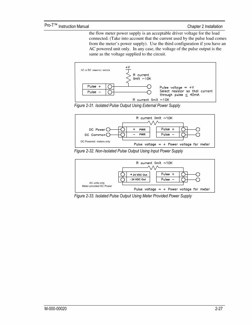
the flow meter power supply is an acceptable driver voltage for the load connected. (Take into account that the current used by the pulse load comes from the meter’s power supply). Use the third configuration if you have an AC powered unit only. In any case, the voltage of the pulse output is the same as the voltage supplied to the circuit.
28
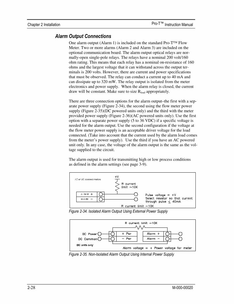
One alarm output (Alarm 1) is included on the standard Pro-T™ Flow Meter. Two or more alarms (Alarm 2 and Alarm 3) are included on the optional communication board. The alarm output optical relays are nor-mally-open single-pole relays. The relays have a nominal 200 volt/160 ohm rating. This means that each relay has a nominal on-resistance of 160 ohms and the largest voltage that it can withstand across the output ter-minals is 200 volts. However, there are current and power specifications that must be observed. The relay can conduct a current up to 40 mA and can dissipate up to 320 mW. The relay output is isolated from the meter electronics and power supply. When the alarm relay is closed, the current draw will be constant. Make sure to size Rload appropriately. There are three connection options for the alarm output–the first with a sep-arate power supply (Figure 2-34), the second using the flow meter power supply (Figure 2-35)(DC powered units only) and the third with the meter provided power supply (Figure 2-36)(AC powered units only). Use the first option with a separate power supply (5 to 36 VDC) if a specific voltage is needed for the alarm output. Use the second configuration if the voltage at the flow meter power supply is an acceptable driver voltage for the load connected. (Take into account that the current used by the alarm load comes from the meter’s power supply). Use the third if you have an AC powered unit only. In any case, the voltage of the alarm output is the same as the vol-tage supplied to the circuit. The alarm output is used for transmitting high or low process conditions as defined in the alarm settings (see page 3-9).

The remote electronics enclosure should be mounted in a convenient, easy to reach location. For hazardous location installations, make sure to ob-serve agency requirements for installation. Allow some slack in the inter-face cable between the junction box and the remote electronics enclosure. To prevent damage to the wiring connections, do not put stress on the terminations at any time. The meter is shipped with temporary strain relief glands at each end of the cable. Disconnect the cable from the meter’s terminal block inside the junction box–not at the remote electronics enclosure. Remove both glands and install appropriate conduit entry glands and conduit. When installa-tion is complete, re-connect each labeled wire to the corresponding ter-minal position on the junction box terminal block. Make sure to connect each wire pair’s shield. Note: incorrect connection will cause the meter to malfunction.
Note: Numeric code in junction box label matches wire labels.
30
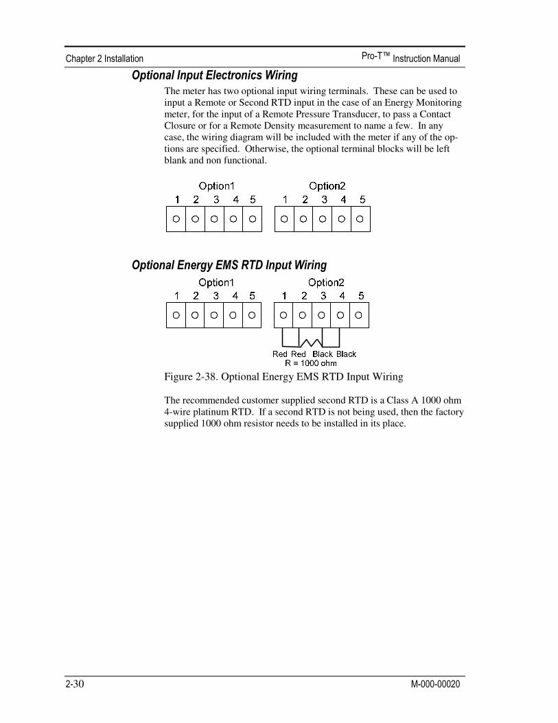
The meter has two optional input wiring terminals. These can be used to input a Remote or Second RTD input in the case of an Energy Monitoring meter, for the input of a Remote Pressure Transducer, to pass a Contact Closure or for a Remote Density measurement to name a few. In any case, the wiring diagram will be included with the meter if any of the op-tions are specified. Otherwise, the optional terminal blocks will be left blank and non functional.
Figure 2-38. Optional Energy EMS RTD Input Wiring The recommended customer supplied second RTD is a Class A 1000 ohm 4-wire platinum RTD. If a second RTD is not being used, then the factory supplied 1000 ohm resistor needs to be installed in its place.

The meter is set to have Option 1 used for the external input. Program-ming menus that pertain to the optional 4-20 mA input are located in the Hidden Diagnostics Menu in Chapter 5.
Follow the above diagram to wire the external 4-20 mA input into the flow meter using an external power supply.
Follow the above diagram to wire the external 4-20 mA input into the flow meter using power supplied to the input of a DC powered meter.

32
Follow the above diagram to wire the external 4-20 mA input into the flow meter using power from the 24 VDC output of an AC powered me-ter.
Follow the above diagram to wire an external switch input into the flow meter. The meter is configured to have Option 1 used for the external in-put. If the above switch is used to remotely reset the totalizer a pushbut-ton switch with a momentary contact closure is recommended.

After installing the Pro-T™ Insertion Turbine Flow Meter, you are ready to begin operation. The sections in this chapter explain the display/keypad commands, meter start-up and programming. The meter is ready to operate at start up without any special pro-gramming. To enter parameters and system settings unique to your operation, see the following pages for instructions on using the setup menus.
The flow meter’s digital electronics allow you to set, adjust and monitor system parameters and performance. A full range of commands are available through the display/keypad. The LCD display gives 2 x 16 characters for flow monitoring and pro-gramming. The six push-buttons can be operated with the enclo-sure cover removed. Or, the explosion-proof cover can remain in place and the keypad operated with a hand-held magnet posi-tioned at the side of the enclosure as shown in the illustration at the left.
VorTek
Instruments, LLC
Pro-VTM

To begin flow meter operation:
1. Verify the flow meter is installed and wired as described in Chapter 2.
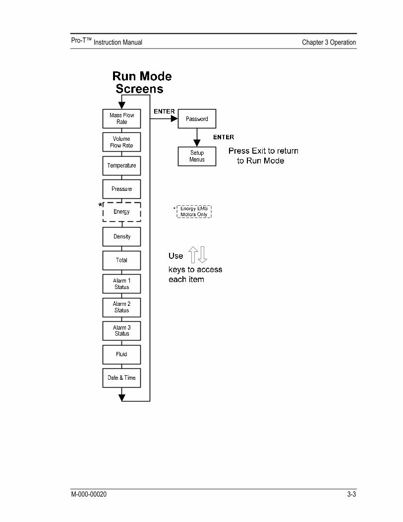
2. Apply power to the meter. At start up, the unit runs a series of self-tests that check the RAM, ROM, EPROM and all flow sensing com-ponents. After completing the self-test sequence, the Run Mode
screens appear.
3. The Run Mode displays flow information as determined by system settings. Some screens depicted on the next page may not be dis-played based on these settings. Press the arrow keys to view the Run Mode screens.
4. Press the key from any Run Mode screen to access the Setup Menus. Use the Setup Menus to configure the meter’s multi-parameter features to fit your application.
EXIT


1. Enter the Setup Menu by pressing the key until prompted for a password. (All
outputs are disabled while using the Setup Menus.) 2. Use the keys to select the password characters (1234 is the factory-set
password). When the password is correctly displayed, press to continue. 3. Use the Setup Menus described on the following pages to customize the multi-
parameter features of your Pro-T™ Flow Meter. (The entire lower display line is available for entering parameters.) Some items depicted in the graphic on the preceding page may not be displayed based on flow meter configuration settings
4. To activate a parameter, press . Use the keys to make selections. Press to continue. Press to save or discard changes and return to Run Mode.
5. Program the UNITS menu first because later menus will be based on the units
selected.

The following shows how to set Output 1 to measure mass flow with 4 mA = 0 lb/hr and 20 mA = 100 lb/hr with a time constant of 5 seconds. (All outputs are disabled while using the Setup Menus.)
1. Use keys to move to the Units Menu (see page 3-12). 2. Press key until Mass Flow Unit appears. Press ENTER. 3. Press key until lb appears in the numerator. Press key to move the underline cursor to the
denominator. Press the key until hr appears in the denominator. Press ENTER to select. 4. Press key until Units Menu appears.
1. Use keys to move to the Output Menu. 2. Press the key until 4-20 mA Output 1 appears. 3. Press key to access Measure selections. Press ENTER and press the key to select Mass. Press ENTER. 4. Press key to set the 4 mA point in the units you have selected for mass of lb/hr. Press ENTER and
use keys to set 0 or 0.0. Press ENTER. 5. Press key to set the 20 mA point. Press ENTER and use keys to set 100 or 100.0. Press ENTER. 6. Press key to select the Time Constant. Press ENTER and use keys to select 5. Press ENTER. 7. Press the EXIT key and answer YES to permanently save your changes.

Use the Display Menu to set the cycle time for automatic screen sequencing used in the Run Mode, change the precision of displayed values, smooth the values or enable or disable each item displayed in the Run Mode screens.
The following shows how to remove the temperature screen from the Run Mode screens. Note: all outputs are disabled while using the Setup Menus. 1. Use keys to move to the Display Menu. 2. Press key until Mf Vf Pr Te De T appears. 3. Press ENTER to select. Press key until the cursor is positioned below Te. 4. Press key until N appears. Press ENTER to select. 5. Press EXIT and then ENTER to save changes and return to the Run Mode.

The following shows how to set Relay Alarm 1 to activate if the mass flow rate is greater than 100 lb/hr. You can check the alarm configuration in the Run Mode by pressing the keys until Alarm [1] appears. The lower line displays the mass flow rate at which the alarm activates. Note: all outputs are disabled while using the Setup Menus.
1. Use keys to move to the Units Menu (see to page 3-12). 2. Press key until Mass Flow Unit appears. Press ENTER. 3. Press key until lb appears in the numerator. Press key to move the underline cursor to the
denominator. Press the key until hr appears in the denominator. Press ENTER to select. 4. Press key until Units Menu appears.
1. Use keys to move to the Alarms Menu. 2. Press the key until Relay Alarm 1 appears. 3. Press key to access Measure selections. Press ENTER and use the key to select Mass. Press ENTER. 4. Press key to select the alarm Mode. Press ENTER and use key to select HIGH Alarm. Press ENTER. 5. Press key to select the value that must be exceeded before the alarm activates. Press ENTER and use
keys to set 100 or 100.0. Press ENTER. 6. Press the EXIT key to save your changes. (Alarm changes are always permanently saved.)
(Up to three relay alarm outputs are available depending on meter configuration.)

Use the Totalizer Menu to configure and monitor the totalizer. The totalizer output is a 50 millisecond (.05 second) positive pulse (relay closed for 50 milliseconds). The totalizer cannot operate faster than one pulse every 100 millisecond (.1 second). A good rule to follow is to set the unit per pulse value equal to the maximum flow in the same units per second. This will limit the pulse to no faster than one pulse every second.
The following shows how to set the totalizer to track mass flow in kg/sec. (All outputs are disabled while using the Setup Menus.)
1. Use keys to move to the Units Menu (see to page 3-12). 2. Press key until Mass Flow Unit appears. Press ENTER. 3. Press key until kg appears in the numerator. Press key to move the underline cursor to the
denominator. Press the key until sec appears in the denominator. Press ENTER to select. 4. Press key until Units Menu appears.
1. Use keys to move to the Totalizer Menu. 2. Press the key until Totaling appears. 3. Press ENTER and press the key to select Mass. Press ENTER. 4. Press key to set the pulse output in the units you have selected for mass flow of kg/sec. Press
ENTER and use keys to set the pulse value equal to the maximum flow in the same units per second. Press ENTER.
5. To reset the totalizer, press key until Reset Total? appears. Press ENTER and the key to reset the totalizer if desired. Press ENTER.
6. Press the EXIT key and answer YES to permanently save your changes.

Use the Totalizer #2 to Monitor Flow or Energy. Note that Totalizer #2 does not operate a relay, it is for monitoring only.

Configuration: There are several possibilities regarding the measurement of water or steam energy given the location of the meter and the use of a second RTD. The table below summarizes the possibilities:
Fluid Meter Location Second RTD Measurement
Water “Sent” Flow Line “Return Flow Line Change in Energy
Water “Return” Flow Line “Sent” Flow Line Change in Energy
Water “Sent” Flow Line None Outgoing Energy
Steam “Sent” Flow Line “Return” Flow Line (condensate)
Change in Energy
Steam “Sent” Flow Line None Outgoing Energy
As above, you must properly configure the meter in the Energy Menu. 1. Loc in Sent Flow? Select Yes or No based on where the meter is located. Refer to the above
table 2. Heating System? Select Yes for a hot water system used for heating. Select No for a chilled
water system used for cooling. Always select Yes for a steam system. 3. % Returned. Select a number between 0% and 100%. Estimate the amount of water that returns.
It is usually 100%, or can be less than 100% if historical data shows the amount of makeup water used. If a second RTD is not used, set to 0%. When 0% is selected, the energy calculation represents the outgoing energy only (no return energy is subtracted). NOTE: the meter ships from the factory assuming 0% return and has a 1000 ohm resistor installed in the RTD #2 wiring location. This needs to be removed if the meter is to be used in a manner other than with 0% return and with the customer supplied RTD in its place.

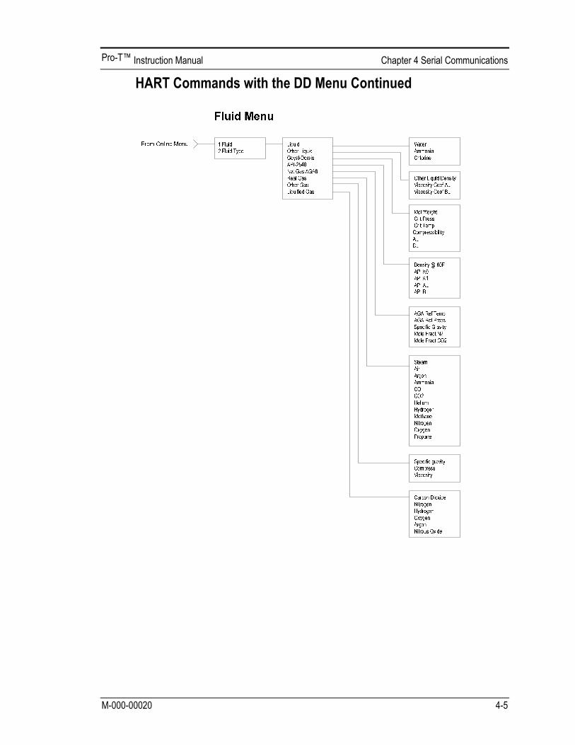
Use the Fluid Menu to configure the flow meter for use with common gases, liquids and steam. Your flow meter is pre-programmed at the factory for your application’s process fluid. Reference Richard W. Miller, Flow Measurement Engineering Handbook (Third Edition, 1996), page 2-75 for definition and use of the Goyal-Doraiswamy equation and page 2-76 for the definition and use of the API 2540 equation. Also, see Appendix C for Fluid Calculation equations. The units of measurement used in the Fluid Menu are preset and are as follows: Mole Weight = lbm/(lbm·mol), CRIT PRESS = psia, CRIT TEMP = °R, Density = Kg/m3 and Viscosity = cP (centipoise).
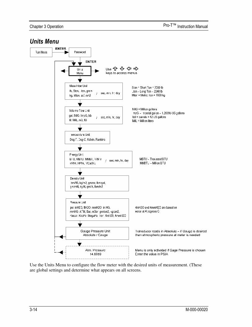
Use the Units Menu to configure the flow meter with the desired units of measurement. (These are global settings and determine what appears on all screens.

Use the Time and Date Menu to enter the correct time and date into the flow meter’s memory. The parameters are used in the Run Mode and the alarm and system log files. Note: Time is displayed in AM/PM format, but military format is used to set the time. For example, 1:00 PM is entered as 13:00:00 in the Set Time menu.
How to set the time to 12:00:00. You can check the time in the Run Mode by pressing the keys until the Time & Date screen appears. Note: all outputs are disabled while using the Setup Menus. 1. Use keys to move to the Time and Date Menu. 2. Press key until Set Time appears. Press ENTER. 3. Press key until 1 appears. Press key to move the underline cursor to the next digit.
Press the key until 2 appears. Continue sequence until all desired parameters are en-tered. Press ENTER to return to the Time and Date Menu.
4. Press to return to the Run Mode.

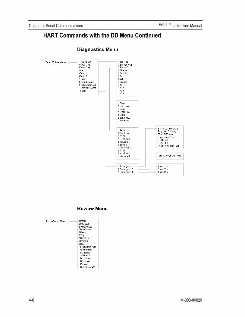
Use the Diagnostics Menu to simulate operation and review the system files. The system log files contain time/date stamped messages including: power on, power off, programming time outs, parameter faults, incorrect password entry and other various information relative to system operation and programming.
The simulated inputs are for testing the meter to verify that the programming is correct. They are also used to enter nominal operating temperature and pressure for the V only model. Simulated turbine frequency allows you to enter any value for the sensor input in Hz. The meter will calculate a flow rate based on the corresponding value and update all analog outputs (the totalizer display and output is not affected by a simulated frequency). The simulated pressure and temperature settings work the same way. The meter will output these new values and will use them to calculate a new density for mass flow measurement. Note: when your diagnostic work is complete, make sure to return the values to zero to allow the electronics to use the actual transducer values. For the V only model keep the temperature and pressure at nominal operating conditions.

If the meter display indicates a temperature or pressure fault, a substitute value can be entered to allow flow calculations to continue at a fixed value until the source of the fault is identified and corrected. The units of measure of the displayed values are the same as the units configured for the flow meter.
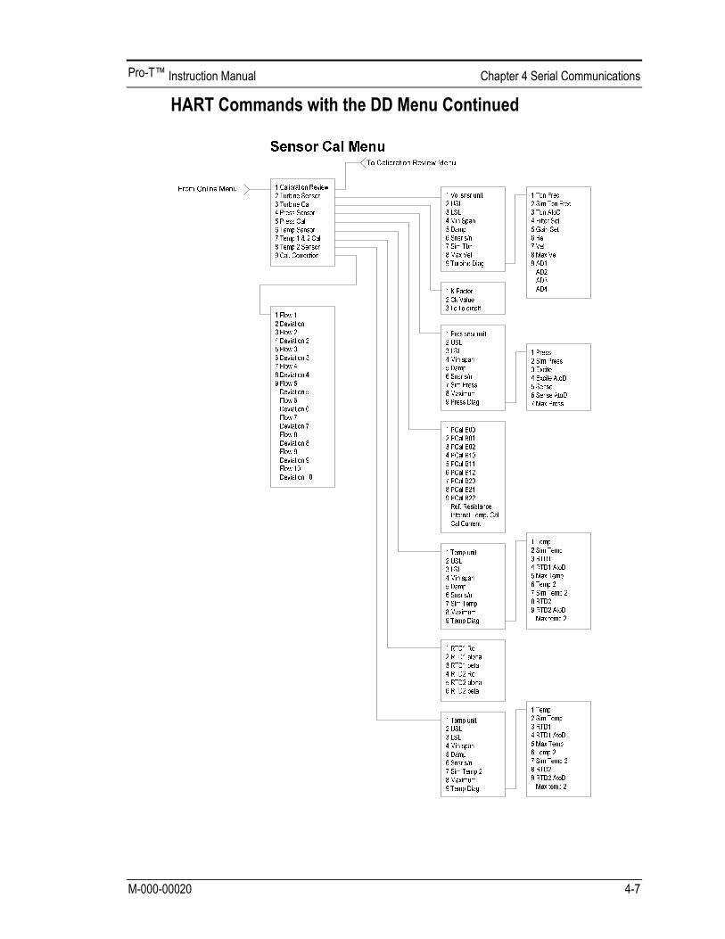
The Calibration Menu contains the calibration coefficients for the flow meter. These values should by changed only by properly trained personnel. The Low Flow Cutoff is set at the factory. Consult the factory for help with these settings if the meter is showing erratic flow rate.
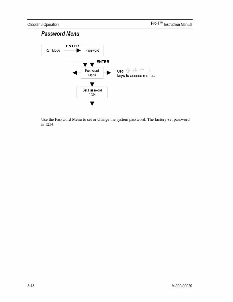
Use the Password Menu to set or change the system password. The factory-set password is 1234.

The HART Communications Protocol (Highway Addressable Remote Trans-ducer Protocol) is a bidirectional digital serial communications protocol. The HART signal is based on the Bell 202 standard and is superimposed on 4-20 mA Output 1. Peer-to-peer (analog / digital) and multi-drop (digital only) modes are supported.
The diagrams below detail the proper connections required for HART communications:

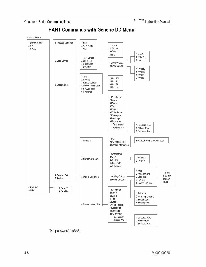
Use password 16363.
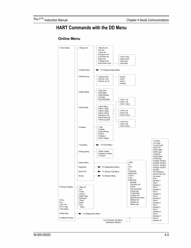
Online Menu

Use password 16363.
Sequence Description Access Notes 1,1,1 Snsr View Primary variable value 1,1,2 AI % Rnge View Analog output % range 1,1,3 AO1 View Analog output, mA 1,2,1 Test Device N/A Not used 1,2,2,1 4 mA View Loop test, fix analog output at 4 mA 1,2,2,2 20 mA View Loop test, fix analog output at 20 mA 1,2,2,3 Other Edit Loop test, fix analog output at mA value entered 1,2,2,4 End Exit loop test 1,2,3,1,1 4 mA N/A Not used, apply values 1,2,3,1,2 20 mA N/A Not used, apply values 1,2,3,1,3 Exit Exit apply values 1,2,3,2,1 PV LRV Edit Primary variable lower range value 1,2,3,2,2 PV URV Edit Primary variable upper range value 1,2,3,2,3 PV USL View Primary variable upper sensor limit 1,2,3,2,4 PV LSL View Primary variable lower sensor limit 1,2,4 D/A Trim Edit Calibrate electronics 4mA and 20mAvalues 1,3,1 Tag Edit Tag 1,3,2 PV unit Edit Primary variable units 1,3,3,1 PV LRV Edit Primary variable lower range value 1,3,3,2 PV URV Edit Primary variable upper range value 1,3,3,3 PV LSL View Primary variable upper sensor limit 1,3,3,4 PV USL View Primary variable lower sensor limit 1,3,4,1 Distributor N/A Not used 1,3,4,2 Model N/A Not used 1,3,4,3 Dev id View Device identification 1,3,4,4 Tag Edit Tag 1,3,4,5 Date Edit Date 1,3,4,6 Write Protect View Write protect 1,3,4,7 Descriptor Edit Turbine flowmeter 1,3,4,8 Message Edit 32 character alphanumeric message 1,3,4,9 PV snsr s/n View Primary variable sensor serial number 1,3,4,menu Final assy # Edit Final assembly number 1,3,4,menu,1 Universal Rev View Universal revision 1,3,4,menu,2 Fld dev Rev View Field device revision 1,3,4,menu,3 Software Rev View Software revision 1,3,5 PV Xfer fnctn View Linear 1,3,6 PV Damp Edit Primary variable damping (time constant) in seconds 1,4,1,1 PV View Primary variable value 1,4,1,2 PV Sensor Unit Edit Primary variable units 1,4,1,3 Sensor Information View PV LSL, PV USL, PV Min span 1,4,2,1 Snsr Damp Edit Primary variable damping (time constant) in seconds 1,4,2,2,1 PV LRV Edit Primary variable low range value 1,4,2,2,2 PV URV Edit Primary variable upper range value 1,4,2,3,1 PV LRV Edit Primary variable low range value 1,4,2,3,2 PV URV Edit Primary variable upper range value 1,4,2,4 Xfer Fnctn View Linear 1,4,2,5 AI % rnge View Analog output % range 1,4,3,1,1 AO1 View Analog output, mA 1,4,3,1,2 AO alarm typ N/A Not used
Continued on next page

Sequence Description Access Notes 1,4,3,1,3,1 4 mA View Loop test, fix analog output at 4 mA 1,4,3,1,3,2 20 mA View Loop test, fix analog output at 20 mA 1,4,3,1,3,3 Other Edit Loop test, fix analog output at mA value entered 1,4,3,1,3,4 End Exit loop test 1,4,3,1,4 D/A trim Edit Calibrate electronics 4mA and 20mAvalues 1,4,3,1,5 Scaled D/A trim N/A Not used 1,4,3,2,1 Poll addr Edit Poll address 1,4,3,2,2 Num req. preams View Number of required preambles 1,4,3,2,3 Burst mode N/A Not used 1,4,3,2,4 Burst option N/A Not used 1,4,4,1 Distributor N/A Not used 1,4,4,2 Model N/A Not used 1,4,4,3 Dev id View Device identification 1,4,4,4 Tag Edit Tag 1,4,4,5 Date Edit Date 1,4,4,6 Write Protect View Write protect 1,4,4,7 Descriptor Edit Turbine flowmeter 1,4,4,8 Message Edit 32 character alphanumeric message 1,4,4,9 PV snsr s/n View Primary variable sensor serial number 1,4,4,menu Final assy # Edit Final assembly number 1,4,4,menu,1 Universal Rev View Universal revision 1,4,4,menu,2 Fld dev Rev View Field device revision 1,4,4,menu,3 Software Rev View Software revision 1,5 Review N/A Not used 2 PV View Primary variable value 3 PV AO View Analog output, mA 4,1 PV LRV Edit Primary variable lower range value 4,2 PV URV Edit Primary variable upper range value 5,1 PV LRV Edit Primary variable lower range value 5,2 PV URV Edit Primary variable upper range value
VorTek Pro-T™ Mass Flow Meters with Modbus communication protocol and
firmware version 4.00.58 and above.
This document describes the preliminary implementation of the Modbus
communication protocol for use in monitoring common process variables in the
VorTek Pro-T™ Insertion Turbine flow meter. The physical layer utilizes the
half-duplex RS-485 port, and the Modbus protocol.
The following documents are available online from www.modbus.org.
Modbus Application Protocol Specification V1.1
Modbus Over Serial Line Specification & Implementation Guide V1.0
Modicon Modbus Protocol Reference Guide PI–MBUS–300 Rev. J
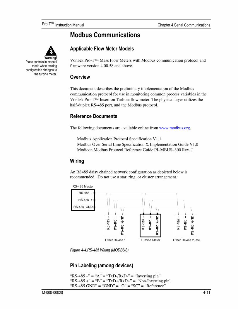
An RS485 daisy chained network configuration as depicted below is recommended. Do not use a star, ring, or cluster arrangement.
“RS-485 –” = “A” = “TxD-/RxD-” = “Inverting pin” “RS-485 +” = “B” = “TxD+/RxD+” = “Non-Inverting pin” “RS-485 GND” = “GND” = “G” = “SC” = “Reference”

The following menu items are in the Output Menu and allow selection and
control of the Modbus communication protocol.
When the Modbus protocol is selected, the Modbus address is equal to the
user programmable device address if it is in the range 1…247, in
accordance with the Modbus specification. If the device address is zero or
is greater than 247, then the Modbus address is internally set to 1.
The Comm Protocol menu allows selection of “Modbus RTU Even,” “Modbus RTU Odd,” or “Modbus RTU None2,” or “Modbus RTU None1,” (non-standard Modbus) with Even, Odd and None referring to the parity selection. When even or odd parity is selected, the unit is configured for 8 data bits, 1 parity bit and 1 stop bit; with no parity, the number of stop bits is 1 (non-standard) or 2. When changing the protocol, the change is made as soon as the Enter key is pressed.
The Modbus Units menu is to control what units, where applicable, the meter’s
variables will be displayed in. Internal – these are the base units of the meter, °F,
psia, lbm/sec , ft3
/sec, Btu/sec , lbm/ft3
Display – variables are displayed in user
selected display unit.
The byte order within registers and the order in which multiple registers
containing floating point or long integer data are transmitted may be changed
with this menu item. According to the Modbus specification, the most
significant byte of a register is transmitted first, followed by the least significant
byte. The Modbus specification does not prescribe the order in which registers
are transmitted when multiple registers represent values longer than 16 bits.
Using this menu item, the order in which registers representing floating point or
long integer data and/or the byte order within the registers may be reversed for
compatibility with some PLCs and PC software.
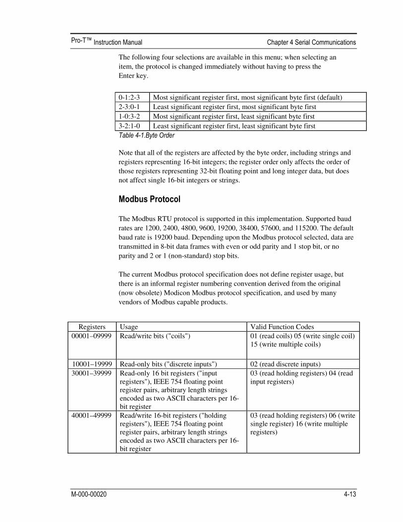
The following four selections are available in this menu; when selecting an
item, the protocol is changed immediately without having to press the
Enter key.
0-1:2-3 Most significant register first, most significant byte first (default)
2-3:0-1 Least significant register first, most significant byte first
1-0:3-2 Most significant register first, least significant byte first
3-2:1-0 Least significant register first, least significant byte first
Note that all of the registers are affected by the byte order, including strings and
registers representing 16-bit integers; the register order only affects the order of
those registers representing 32-bit floating point and long integer data, but does
not affect single 16-bit integers or strings.
The Modbus RTU protocol is supported in this implementation. Supported baud
rates are 1200, 2400, 4800, 9600, 19200, 38400, 57600, and 115200. The default
baud rate is 19200 baud. Depending upon the Modbus protocol selected, data are
transmitted in 8-bit data frames with even or odd parity and 1 stop bit, or no
parity and 2 or 1 (non-standard) stop bits.
The current Modbus protocol specification does not define register usage, but
there is an informal register numbering convention derived from the original
(now obsolete) Modicon Modbus protocol specification, and used by many
vendors of Modbus capable products.
Registers Usage Valid Function Codes
00001–09999 Read/write bits ("coils") 01 (read coils) 05 (write single coil) 15 (write multiple coils)
10001–19999 Read-only bits ("discrete inputs") 02 (read discrete inputs)
30001–39999 Read-only 16 bit registers ("input registers"), IEEE 754 floating point register pairs, arbitrary length strings encoded as two ASCII characters per 16-bit register
03 (read holding registers) 04 (read input registers)
40001–49999 Read/write 16-bit registers ("holding registers"), IEEE 754 floating point register pairs, arbitrary length strings encoded as two ASCII characters per 16-bit register
03 (read holding registers) 06 (write single register) 16 (write multiple registers)
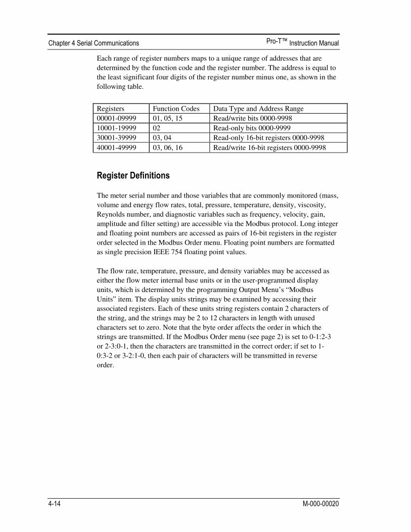
Each range of register numbers maps to a unique range of addresses that are
determined by the function code and the register number. The address is equal to
the least significant four digits of the register number minus one, as shown in the
following table.
Registers Function Codes Data Type and Address Range
00001-09999 01, 05, 15 Read/write bits 0000-9998
10001-19999 02 Read-only bits 0000-9999
30001-39999 03, 04 Read-only 16-bit registers 0000-9998
40001-49999 03, 06, 16 Read/write 16-bit registers 0000-9998
The meter serial number and those variables that are commonly monitored (mass,
volume and energy flow rates, total, pressure, temperature, density, viscosity,
Reynolds number, and diagnostic variables such as frequency, velocity, gain,
amplitude and filter setting) are accessible via the Modbus protocol. Long integer
and floating point numbers are accessed as pairs of 16-bit registers in the register
order selected in the Modbus Order menu. Floating point numbers are formatted
as single precision IEEE 754 floating point values.
The flow rate, temperature, pressure, and density variables may be accessed as
either the flow meter internal base units or in the user-programmed display
units, which is determined by the programming Output Menu’s “Modbus
Units” item. The display units strings may be examined by accessing their
associated registers. Each of these units string registers contain 2 characters of
the string, and the strings may be 2 to 12 characters in length with unused
characters set to zero. Note that the byte order affects the order in which the
strings are transmitted. If the Modbus Order menu (see page 2) is set to 0-1:2-3
or 2-3:0-1, then the characters are transmitted in the correct order; if set to 1-
0:3-2 or 3-2:1-0, then each pair of characters will be transmitted in reverse
order.
Registers Variable Data type Units Function
code Addresses
65100-65101 Serial number unsigned long — 03, 04
30525-30526 Totalizer unsigned long display units* 03, 04 524-525
32037-32042 Totalizer units string — 03, 04 2036-2041
30009-30010 Mass flow float display units* 03, 04 8-9
30007-30008 Volume flow float display units* 03, 04 6-7
30005-30006 Pressure float display units* 03, 04 4-5
30001-30002 Temperature float display units* 03, 04 0-1
30029-30030 Velocity float ft/sec 03, 04 28-29
30015-30016 Density float display units* 03, 04 14-15
30013-30014 Viscosity float cP 03, 04 12-13
30031-30032 Reynolds number float — 03, 04 30-31
30025-30026 Turbine frequency float Hz 03, 04 24-25
34532 Gain char — 03, 04 4531
30085-30086 Turbine amplitude float Vrms 03, 04 84-85
30027-30028 Filter setting float Hz 03, 04 26-27
The following registers are available with the energy meter firmware:
Registers Variable Data type Units Function code
Addresses
30527-30528 Totalizer #2 unsigned long display units* 03, 04 526-527
32043-32048 Totalizer #2 units string — 03, 04 2042-2047
30003-30004 Temperature #2 float display units* 03, 04 2-3
30011-30012 Energy flow float display units* 03, 04 10-11
The following registers contain the display units strings:
Registers Variable Data type Units Function code Addresses
32007-32012 Volume flow units string — 03, 04 2006-2011
32001-32006 Mass flow units string — 03, 04 2000-2005
32025-32030 Temperature units string — 03, 04 2024-2029
32019-32024 Pressure units string — 03, 04 2018-2023
32031-32036 Density units string — 03, 04 2030-2035
32013-32017 Energy flow units string — 03, 04 2012-2017
Function codes 03 (read holding registers) and 04 (read input registers) are the
only codes supported for reading these registers, and function codes for writing
holding registers are not implemented. We recommend that the floating point and
long integer registers be read in a single operation with the number of registers
being a multiple of two. If these data are read in two separate operations, each
reading a single 16-bit register, then the value will likely be invalid.

The floating point registers with values in display units are scaled to the same
units as are displayed, but are instantaneous values that are not smoothed. If
display smoothing is enabled (non-zero value entered in the Display TC item
in the Display Menu), then the register values will not agree exactly with the
displayed values.
The Read Exception Status command (function code 07) returns the exception
status byte, which is defined as follows. This byte may be cleared by setting
“coil” register #00003 (function code 5, address 2, data = 0xff00).
Bit(s) Definition
0-1 Byte order (see Modbus Order on page 2)
0 = 3-2:1-0 1 = 2-3:0-1 2 = 1-0:3-2 3 = 0-1:2-3
2 Temperature sensor fault
3 Pressure sensor fault
4 A/D converter fault
5 Period overflow
6 Pulse overflow
7 Configuration changed
The status of the three alarms may be monitored via the Modbus Read Discrete
Input command (function code 02). The value returned indicates the state of the
alarm, and will be 1 only if the alarm is enabled and active. A zero value is
transmitted for alarms that are either disabled or inactive,
Registers Variable Function Code Address
10001 Alarm #1 state 02 0
10002 Alarm #2 state 02 1
10003 Alarm #3 state 02 2

The only writeable registers in this implementation are the Reset Exception
Status, Reset Meter and Reset Totalizer functions, which are implemented as
”coils” which may be written with the Write Single Coil command (function
code 05) to address 8 through 10, respectively, (register #00009 through #00011).
The value sent with this command must be either 0x0000 or 0xff00, or the meter
will respond with an error message; the totalizer will be reset or exception status
cleared only with a value of 0xff00.
If an error is detected in the message received by the unit, the function code
in the response is the received function code with the most significant bit set,
and the data field will contain the exception code byte, as follows:
If the first byte of a message is not equal to the unit’s Modbus address, if the
unit detects a parity error in any character in the received message (with even or
odd parity enabled), or if the message CRC is incorrect, the unit will not
respond.
The start address is equal to the desired first register number minus one. The
addresses derived from the start address and the number of registers must all be
mapped to valid defined registers, or an invalid data address exception will occur.
Exception
Code Description
01 Invalid function code — function code not supported by device
02 Invalid data address — address defined by the start address and number of registers
is out of range
03 Invalid data value — number of registers = 0 or >125 or incorrect data with the Write
Single Coil command

Read the exception status byte from the device with address 1:
01 07 41 E2
01 Device address 07 Function code, 04 = read exception status
A typical response from the device is as follows:
01 07 03 62 31
01 Device address 07 Function code 03 Exception status byte 62 31 CRC
Request the first 12 registers from device with address 1:
01 04 00 00 00 0C F0 0F
01 Device address 04 Function code, 04 = read input register 00 00 Starting address 00 0C Number of registers = 12 F0 0F CRC
A typical response from the device is as follows: *note these are the older register definitions
01 04 18 00 00 03 E8 00 00 7A 02 6C 62 00 00 41 BA 87 F2 3E BF FC 6F 42 12 EC 8B 4D D1
01 Device address 04 Function code 18 Number of data bytes = 24 00 00 03 E8 Serial number = 1000 (unsigned long) 00 00 7A 02 Totalizer = 31234 lbm (unsigned long) 6C 62 00 00 Totalizer units = “lb” (string, unused characters are 0) 41 BA 87 F2 Mass flow rate = 23.3164 lbm/sec (float)
3E BF FC 6F Volume flow rate = 0.3750 ft3
/sec (float) 42 12 EC 8B Pressure = 36.731 psia (float) 4D D1 CRC
An attempt to read register(s) that don’t exist 01 04 00 00 00 50 F1 D2
01 Device address
04 Function code 4 = read input register 00 00 Starting address 00 50 Number of registers = 80 F0 36 CRC
results in an error response as follows:
01 84 02 C2 C1
01 Device address 84 Function code with most significant bit set indicates error response 02 Exception code 2 = invalid data address C2 C1 CRC
Request the state all three alarms:
01 02 00 00 00 03 38 0B
01 Device address 02 Function code 2 = read discrete inputs 00 00 Starting address 00 03 Number of inputs = 3 38 0B CRC
and the unit responds with:
01 02 01 02 20 49
01 Device address 02 Function code 01 Number of data bytes = 1 02 Alarm #2 on, alarms #1 and #3 off 20 49 CRC
To reset the totalizer:
01 05 00 00 FF 00 8C 3A
01 Device address 05 Function code 5 = write single coil 00 09 Coil address = 9 FF 00 Data to reset totalizer 8C 3A CRC (not the correct CRC EJS-02-06-07)

The unit responds with an identical message to that transmitted, and the totalizer
is reset. If the “coil” is turned off as in the following message, the response is
also identical to the transmitted message, but the totalizer is not affected.
01 05 00 00 00 00 CD CA
01 Device address 05 Function code 5 = write single coil 00 00 Coil address = 0 00 00 Data to “turn off coil” does not reset totalizer CD CA CRC

The menus shown on the following page can be accessed using the password 16363, then moving to the display that reads “Diagnostics Menu” and pressing ENTER (rather than one of the arrow keys). Use the right arrow key to move to the second column. Press EXIT to move from the second column back to the first, press EXIT while in the first column to return to the setup menus. Caution: password 16363 will allow full access to the configuration and should be used carefully to avoid changes that can adversely alter the function of the meter. Each of the menus on the following page will first be defined followed by specific troubleshooting steps.
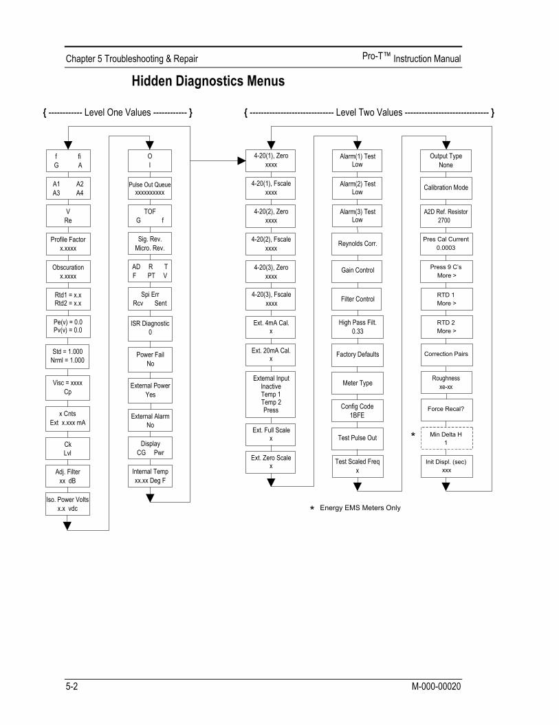

• f = Turbine frequency (Hz).
• fi = Adaptive filter – should be approximately 25% higher than the turbine frequency, this is a low-pass filter. If the meter is using the Filter Control (see below) in the manual mode, fi will be displayed as fm.
• G = Gain (applied to turbine signal amplitude). Gain defaults to 1.0 and can be changed using the Gain Control (see below).
• A = Amplitude of turbine signal in Volts rms.
• A1, A2, A3, A4 = A/D counts representing the turbine signal amplitude. Each stage (A1-A4) cannot exceed 512. Beginning with stage A1, the A/D counts increase as the flow increases. When stage A1 reaches 512, it will shift to stage A2. This will continue as the flow rate increases until all 4 stages read 512 at high flow rates. Higher flow rates (stronger signal strength) will result in more stages reading 512.
• V = Calculated average pipe velocity (ft/sec).
• Re = Calculated Reynolds number.
• Profile Factor = Factory use only.
• Obscuration Factor = Factory use only.
• RTD1 = Resistance value of integral RTD in ohms.
• RTD2 = Optional RTD resistance value in ohms.
• Pe(v) = Pressure transducer excitation voltage
• Pv(v) = Pressure transducer sense voltage.
• Stnd = Density of fluid at standard conditions.
• Nrml = Density of fluid at normal conditions.
• Viscosity = Calculated viscosity of flowing fluid.
• x Cnts = A/D counts from the external 4-20 mA input.
• Ext x.xxx mA = Calculated external 4-20 mA input from the digital counts.
• Ck = Calculated Ck at current operating conditions. Ck is a variable in the equation that relates signal strength, density, and velocity for a given application. It is used for noise rejection purposes. Ck directly controls the fi value (see above). If the Ck is set too low (in the calibration menu), then the fi value will be too low and the turbine signal will be rejected resulting in zero flow rate being displayed. The calculated Ck value in this menu can be compared to the actual Ck setting in the calibration menu to help determine if the Ck setting is correct.

• Lvl = Threshold level. If the Low Flow Cutoff in the calibration menu is set above this value, the meter will read zero flow. The Lvl level can be checked at no flow. At no flow, the Lvl must be below the Low Flow Cutoff setting or the meter will have an output at no flow.
• Adj. Flilter = Adjustable filter. Displays the filtering in decibels. Normally reads zero. If this value is consistently -5 or -10, for example, the Ck or density setting may be wrong.
• Iso. Power Volts = Nominally 2.7 VDC, if less than this check the flow meter input power.
• O,I = Factory use only.
• Pulse Out Queue = Pulse output queue. This value will accumulate if the totalizer is accumulating faster than the pulse output hardware can function. The queue will allow the pulses to “catch up” later if the flow rate decreases. A better practice is to slow down the totalizer pulse by increasing the value in the (unit)/pulse setting in the totalizer menu.
• TOF, G, f = Factory use only.
• Sig. Rev = Signal board hardware and firmware revision.
• Miro Rev = Microprocessor board hardware and firmware revision.
• AD, R, T, F, PT, V = Factory use only.
• SPI Err, Rcv, Sent = Factory use only.
• ISR Diagnostic = Factory use only.
• Power Fail = Factory use only.
• External Power = Factory use only.
• External Alarm = Factory use only.
• Display CG, PWR = Factory use only.
• Internal Temperature = Electronics temperature.
• 4-20(1) Zero = Analog counts to calibrate zero on analog output 1.
• 4-20(1) FScale = Analog counts to cal. full scale on analog output 1.
• 4-20(2) Zero = Analog counts to calibrate zero on analog output 2.
• 4-20(2) FScale = Analog counts to cal. full scale on analog output 2.
• 4-20(3) Zero = Analog counts to calibrate zero on analog output 3.
• 4-20(3) FScale = Analog counts to cal. full scale on analog output 3.
• Ext. 4 mA Cal. = Enter 0 for auto calibration or enter factory supplied A/D counts. Note: You must connect a known 4.00 mA input if you are going to calibrate the unit.
• Ext. 20 mA Cal. = Enter 0 for auto calibration or enter factory supplied A/D counts. Note: You must connect a known 20.00 mA input if you are going to calibrate the unit.
• External Input = Enter what the external 4-20 mA input represents, i.e. Temperature 1, Temperature 2, or Pressure. The meter will use this for its internal calculations.
• Ext. Full Scale = Enter the full scale units that correlate to the 20 mA point. Note: It must be in the units for the selected input type such as Deg F, Deg C, PSIA, Bar A, etc.
• Ext. Zero Scale = Same as above but for the 4 mA point.
• Alarm (1) Test = Used as a test to verify that the alarm circuit is functioning. When low is selected the alarm will initiate a low alarm on the output. When High is selected it will give a high alarm on the output.
• Alarm (2) Test = Used as a test to verify that the alarm circuit is functioning. When low is selected the alarm will initiate a low alarm on the output. When High is selected it will give a high alarm on the output.
• Alarm (3) Test = Used as a test to verify that the alarm circuit is functioning. When low is selected the alarm will initiate a low alarm on the output. When High is selected it will give a high alarm on the output.
• Reynolds Corr. = Reynolds number correction for the flow profile.
• Gain Control = Manual gain control (factory use only). Leave set at 1.
• Filter control = Manual filter control. This value can be changed to any number to force the fi value to a constant. A value of zero activates the automatic filter control which sets fi at a level that floats above the f value.
• High Pass Filter = Filter setting – Factory use only
• Factory Defaults = Reset factory defaults. If you change this to Yes and press Enter, all the factory configuration is lost and you must reconfigure the entire program. Consult the factory before performing this process, it is required only in very rare cases.

• Config Code = Factory use only.
• Test Pulse Out = Force totalizer pulse. Set to Yes and press enter to send one pulse. Very useful to test totalizer counting equipment.
• Test Scaled Freq = Enter a frequency value in order to test the scaled frequency output. Return to 0 to stop the test.
• Output Type = Factory use only.
• Calibration Mode = Factory use only.
• A2D Ref. Resistor = Factory use only.
• Pressure Cal Current = Calibration value for the electronics and pressure transducer combination. Consult Factory for value.
• Pressure 9Cs = Nine pressure coefficients unique to the pressure transducer. Use the RIGHT ARROW to access all nine coefficients.
o Press. Max psi = Based on installed sensor.
• Press. Min psi = 0 psiaRTD1. Press the RIGHT ARROW to access:
o Ro = RTD resistance at 0°C (1000 ohms).
o A = RTD coefficient A (.0039083).
o B = RTD coefficient B (-5.775e-07).
o RTD1 Max Deg. F = 500
o RTD1 Min Deg. F = -330
• RTD2 = Second RTD configuration, for special applications only.
• Correction Pairs
o ft3/sec (1 through 10)
o %Dev. (1 through 10)
• Roughness = Factory use only.
• Force Recal? = Factory use only.
• Min. Delta H – Energy EMS meters only. Sets the deadband for totalization to begin. Must be greater than this number (1 default) to initiate the totalizer.
• Init Displ. (sec) = Enter a value in seconds to initialize the display every xxx seconds. Enter a value of 0 to disable initializing the display.

To check the 4–20 mA circuit, connect a DVM in series with the output loop. Select zero or full scale (from the second column of the hidden diagnostics) and then actuate the enter key twice. This action will cause the meter to output its 4 mA or 20 mA conditions. If the DVM indicates a current greater than ± 0.006 mA from 4 or 20, adjust the setting up or down until the output is calibrated. Note: these settings are not for adjusting the output zero and span to match a flow range, that function is located in the Output Menu.

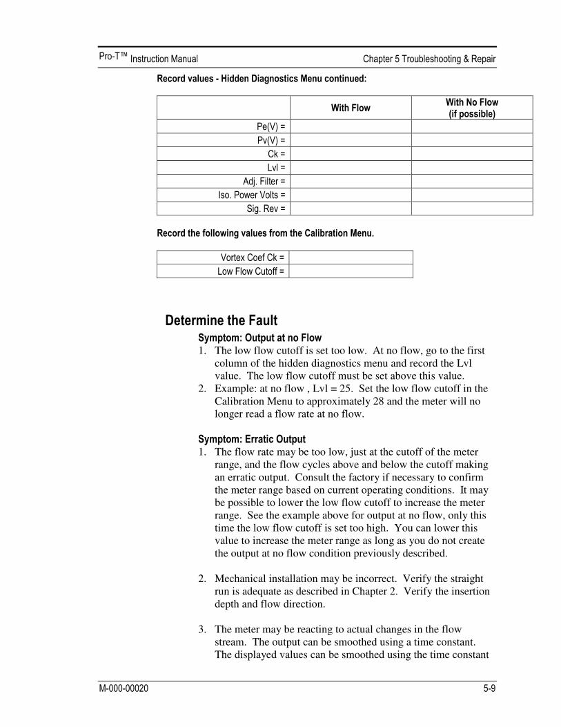
1. The low flow cutoff is set too low. At no flow, go to the first
column of the hidden diagnostics menu and record the Lvl value. The low flow cutoff must be set above this value.
2. Example: at no flow , Lvl = 25. Set the low flow cutoff in the Calibration Menu to approximately 28 and the meter will no longer read a flow rate at no flow.
1. The flow rate may be too low, just at the cutoff of the meter
range, and the flow cycles above and below the cutoff making an erratic output. Consult the factory if necessary to confirm the meter range based on current operating conditions. It may be possible to lower the low flow cutoff to increase the meter range. See the example above for output at no flow, only this time the low flow cutoff is set too high. You can lower this value to increase the meter range as long as you do not create the output at no flow condition previously described.
2. Mechanical installation may be incorrect. Verify the straight
run is adequate as described in Chapter 2. Verify the insertion depth and flow direction.
3. The meter may be reacting to actual changes in the flow
stream. The output can be smoothed using a time constant. The displayed values can be smoothed using the time constant

in the Display Menu. The analog outputs can be smoothed using the time constant in the Output Menu. A time constant of 1 will result in the change in value reaching 63% of its final value in one second. A time constant of 4 is 22%, 10 is 9.5% and 50 is 1.9% of the final value in one second. The time constant equation is shown below (TC = Time Constant).
4. The coefficient Ck may be incorrectly set. The Ck is a value in the equation used to determine if a frequency represents a valid turbine signal given the fluid density and signal amplitude. In practice, the Ck value controls the adaptive filter, fi, setting. During flow, view the f and fi values in the first column of the hidden diagnostics. The fi value should be approximately 10-20 % higher than the f value. If you raise the Ck setting in the Calibration Menu, then the fi value will increase. The fi is a low pass filter, so by increasing it or lowering it, you can alter the range of frequencies that the meter will accept. If the turbine signal is strong, the fi value will increase to a large number – this is correct.
% change to final value in one second = 100 (1 – e(-1/TC))
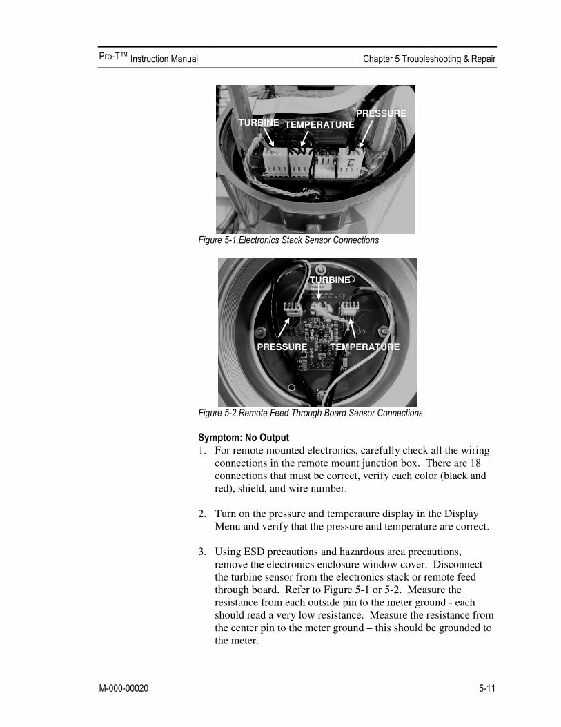
1. 2.
3.
For remote mounted electronics, carefully check all the wiring connections in the remote mount junction box. There are 18 connections that must be correct, verify each color (black and red), shield, and wire number. Turn on the pressure and temperature display in the Display Menu and verify that the pressure and temperature are correct. Using ESD precautions and hazardous area precautions, remove the electronics enclosure window cover. Disconnect the turbine sensor from the electronics stack or remote feed through board. Refer to Figure 5-1 or 5-2. Measure the resistance from each outside pin to the meter ground should read a very low resistance. Measure the resistance from the center pin to the meter ground – this should be grounded to the meter.
TURBINE TEMPERATURE
PRESSURE
TURBINE
TEMPERATURE PRESSURE
For remote mounted electronics, carefully check all the wiring connections in the remote mount junction box. There are 18 connections that must be correct, verify each color (black and
Turn on the pressure and temperature display in the Display perature are correct.
Using ESD precautions and hazardous area precautions, remove the electronics enclosure window cover. Disconnect
electronics stack or remote feed Measure the
sistance from each outside pin to the meter ground - each . Measure the resistance from
this should be grounded to

With the sensor still disconnected, go to the first column of the hidden diagnostics and display the finger on the three exposed pins on the analog board. The meter should read electrical noise, 60 Hz for ereadings are correct, re
4. Verify all meter configuration and troubleshooting steps
previously described. There are many possible causes of this problem, consult factory if necessary.
1. For remote mounted electronics, carefully check all the wiring
connections in the remote mount junction box. There are 18 connections that must be correct, verify each color (black and red), shield, and wire number.
2. Go to the first colu
resistance of the rtd1. It should be about 1080 ohms at room temperature.
3. Using ESD precautions and hazardous area precautions,
remove the electronics enclosure window cover. Disconnect the temperature sensor ffeed through boardresistance across the outside pins of the temperature sensor connector. It should read approximately 1080 ohms at room temperature (higher resistance at
With the sensor still disconnected, go to the first column of the hidden diagnostics and display the turbine frequency, f. Hold a finger on the three exposed pins on the analog board. The meter should read electrical noise, 60 Hz for example. If all readings are correct, re-install turbine sensor wires.
Verify all meter configuration and troubleshooting steps previously described. There are many possible causes of this problem, consult factory if necessary.
For remote mounted electronics, carefully check all the wiring connections in the remote mount junction box. There are 18 connections that must be correct, verify each color (black and red), shield, and wire number.
Go to the first column of the hidden diagnostics and check the resistance of the rtd1. It should be about 1080 ohms at room temperature.
Using ESD precautions and hazardous area precautions, remove the electronics enclosure window cover. Disconnect the temperature sensor from the electronics stack or the remote feed through board. Refer to Figure 5-1 or 5-2. Measure the resistance across the outside pins of the temperature sensor connector. It should read approximately 1080 ohms at room temperature (higher resistance at higher temperatures).
OUTSIDE
OUTSIDE
INSIDE
With the sensor still disconnected, go to the first column of the frequency, f. Hold a
finger on the three exposed pins on the analog board. The xample. If all
Verify all meter configuration and troubleshooting steps previously described. There are many possible causes of this
For remote mounted electronics, carefully check all the wiring connections in the remote mount junction box. There are 18 connections that must be correct, verify each color (black and
mn of the hidden diagnostics and check the resistance of the rtd1. It should be about 1080 ohms at room
Using ESD precautions and hazardous area precautions, remove the electronics enclosure window cover. Disconnect
electronics stack or the remote Measure the
resistance across the outside pins of the temperature sensor connector. It should read approximately 1080 ohms at room
higher temperatures).
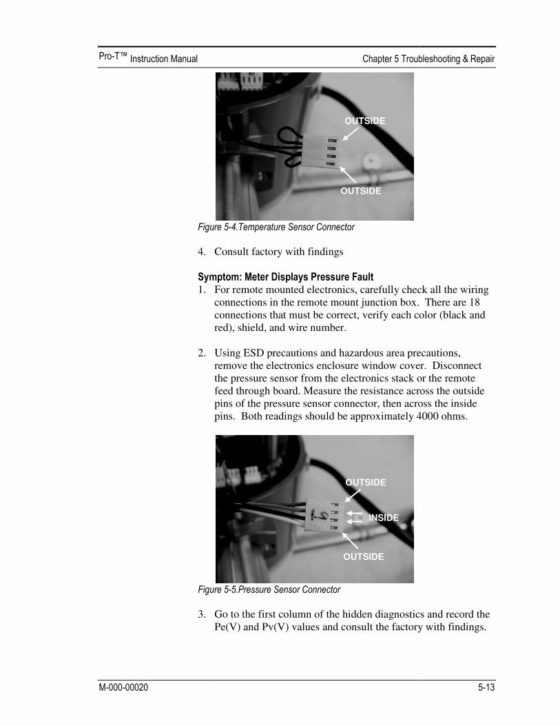
4. 1. 2.
3.
Consult factory with findings
For remote mounted electronics, carefully check all the wiring connections in the remote mount junction box. There are 18 connections that must be correct, verify each color (black and red), shield, and wire number. Using ESD precautions and hazardous area precautions, remove the electronics enclosure window cover. Disconnect the pressure sensor from the electronics stack or the remote feed through board. Measure the resistance across the outside pins of the pressure sensor connector, then across the inside pins. Both readings should be approximately 4000 ohms.
Go to the first column of the hidden diagnostics and record the Pe(V) and Pv(V) values and consult the factory with findings.
OUTSIDE
OUTSIDE
OUTSIDE
OUTSIDE
INSIDE
For remote mounted electronics, carefully check all the wiring junction box. There are 18
connections that must be correct, verify each color (black and
Using ESD precautions and hazardous area precautions, remove the electronics enclosure window cover. Disconnect
electronics stack or the remote . Measure the resistance across the outside sensor connector, then across the inside
pins. Both readings should be approximately 4000 ohms.
Go to the first column of the hidden diagnostics and record the alues and consult the factory with findings.

The electronics boards are electrostatically sensitive. Wear a grounding wrist strap and make sure to observe proper handling precautions required for static-sensitive components. 1. Turn off power to the unit. 2. Locate and loosen the small set screw which locks the larger
enclosure cover in place. Unscrew the cover to expose the electronics stack.
3. Locate the sensor harnesses which come up from the neck of
the flow meter and attaches to the circuit boards. Make note of the location of each sensor connection. Refer to figures 5-1 and 5-2. The turbine sensor connection is on the left, the temperature sensor connection (if present) is second form the left, and the pressure sensor connection (if present) is the right most connector. Use small pliers to pull the sensor wiring connectors off of the circuit boards.
4. Locate and loosen the small set screw which locks the smaller enclosure cover in place. Unscrew the cover to expose the field wiring strip. Tag and remove the field wires.
5. Remove the screws that hold the black wiring label in place,
remove the label. 6. Locate the 4 Phillips head screws which are spaced at 90-
degrees around the terminal board. These screws hold the electronics stack in the enclosure. Loosen these screws (Note: that these are captive screws, they will stay inside the enclosure).
7. Carefully remove the electronics stack from the opposite side
of the enclosure. If the electronics stack will not come out, gently tap the terminal strip with the screw driver handle. This will loosen the rubber sealing gasket on the other side of the enclosure wall. Be careful that the stack does not hang up on the loose sensor harnesses.
8. Repeat steps 1 through 6 in reverse order to install the new
electronics stack.

Before returning any Pro-T flow meter to the factory, you must request a Return Material Authorization (RMA) number. To obtain an RMA number and the correct shipping address, contact Customer Service at:
888-386-7835 or 303-682-9999 in the USA,
When contacting Customer Service, be sure to have the meter serial number and model code. Please see the Meter Troubleshooting Checklist for additional items which may help with problem isolation. When requesting further troubleshooting guidance, please record the values on the checklist at no flow and during flow if possible.


Accuracy
Process Variables
Pro-T™ Insertion Meters(1)
Liquid, Gas & Steam
Mass Flow Rate
±2% of rate(2) over a 30:1 range(3)
Volumetric Flow Rate
±1.5% of rate over a 30:1 range(3)
Temperature ± 2° F
(± 1° C)
Pressure 0.3% of
transducer full scale Density
0.5% of reading(2)
Notes: (1) Accuracies stated are for the total mass flow through the pipe. (2) Over 50 to 100% of the pressure transducer’s full scale. (3) Nominal rangeability is stated. Precise rangeability depends on fluid and pipe size.
Repeatability Mass Flow Rate: 0.2% of rate. Volumetric Flow Rate: 0.1% of rate. Temperature: ± 0.2° F (± 0.1° C). Pressure: 0.05% of full scale. Density: 0.1% of reading. Stability Over 12 Months Mass Flow Rate: 0.2% of rate maximum. Volumetric Flow Rate: Negligible error. Temperature: ± 0.1° F (± 0.5° C) maximum. Pressure: 0.1% of full scale maximum. Density: 0.1% of reading maximum. Response Time Adjustable from 1 to 100 seconds. Material Capability Any gas, liquid or steam compatible with 316L stainless steel. Not
recommended for multi-phase fluids. Flow Rates Typical mass flow ranges are given in the following tables. Precise
flow depends on the fluid and pipe size. Consult factory for sizing program.
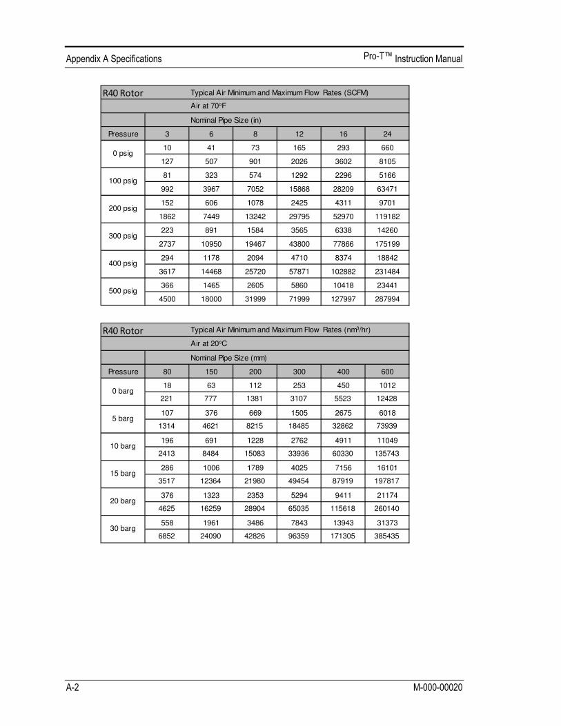
Typical Air Minimum and Maximum Flow Rates (SCFM)
Air at 70oF
Nominal Pipe Size (in)
Pressure 3 6 8 12 16 24
10 41 73 165 293 660
127 507 901 2026 3602 8105
81 323 574 1292 2296 5166
992 3967 7052 15868 28209 63471
152 606 1078 2425 4311 9701
1862 7449 13242 29795 52970 119182
223 891 1584 3565 6338 14260
2737 10950 19467 43800 77866 175199
294 1178 2094 4710 8374 18842
3617 14468 25720 57871 102882 231484
366 1465 2605 5860 10418 23441
4500 18000 31999 71999 127997 287994
400 psig
0 psig
500 psig
100 psig
200 psig
300 psig
Typical Air Minimum and Maximum Flow Rates (nm3/hr)
Air at 20oC
Nominal Pipe Size (mm)
Pressure 80 150 200 300 400 600
18 63 112 253 450 1012
221 777 1381 3107 5523 12428
107 376 669 1505 2675 6018
1314 4621 8215 18485 32862 73939
196 691 1228 2762 4911 11049
2413 8484 15083 33936 60330 135743
286 1006 1789 4025 7156 16101
3517 12364 21980 49454 87919 197817
376 1323 2353 5294 9411 21174
4625 16259 28904 65035 115618 260140
558 1961 3486 7843 13943 31373
6852 24090 42826 96359 171305 385435
0 barg
5 barg
10 barg
15 barg
20 barg
30 barg
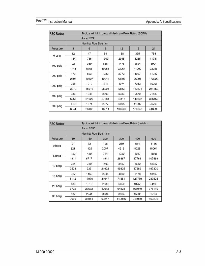
Typical Air Minimum and Maximum Flow Rates (SCFM)
Air at 70oF
Nominal Pipe Size (in)
Pressure 3 6 8 12 16 24
12 47 84 188 335 754
184 736 1309 2945 5236 11781
92 369 656 1476 2624 5904
1441 5766 10251 23064 41002 92255
173 693 1232 2772 4927 11087
2707 10827 19248 43307 76991 173229
255 1019 1811 4074 7243 16298
3979 15916 28294 63663 113178 254650
336 1346 2393 5383 9570 21533
5257 21029 37384 84115 149537 336459
419 1674 2977 6698 11907 26790
6541 26162 46511 104649 186043 418596
0 psig
100 psig
200 psig
300 psig
400 psig
500 psig
Typical Air Minimum and Maximum Flow Rates (nm3/hr)
Air at 20oC
Nominal Pipe Size (mm)
Pressure 80 150 200 300 400 600
21 72 128 289 514 1156
321 1129 2007 4516 8028 18064
122 430 764 1720 3057 6878
1911 6717 11941 26867 47764 107469
224 789 1403 3157 5612 12627
3508 12331 21922 49325 87689 197300
327 1150 2045 4600 8178 18402
5112 17970 31947 71881 127789 287525
430 1512 2689 6050 10755 24199
6722 23632 42012 94528 168049 378110
637 2241 3984 8964 15935 35854
9960 35014 62247 140056 248989 560226
0 barg
5 barg
10 barg
15 barg
20 barg
30 barg
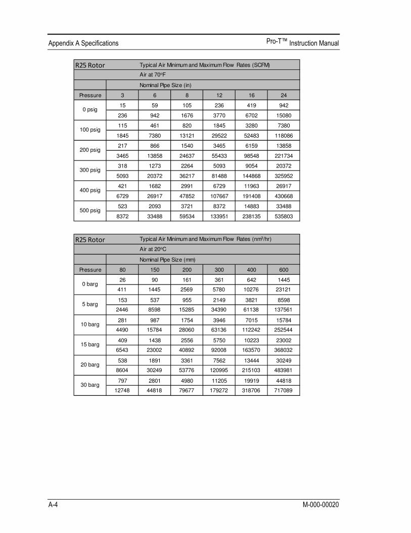
Typical Air Minimum and Maximum Flow Rates (SCFM)
Air at 70oF
Nominal Pipe Size (in)
Pressure 3 6 8 12 16 24
15 59 105 236 419 942
236 942 1676 3770 6702 15080
115 461 820 1845 3280 7380
1845 7380 13121 29522 52483 118086
217 866 1540 3465 6159 13858
3465 13858 24637 55433 98548 221734
318 1273 2264 5093 9054 20372
5093 20372 36217 81488 144868 325952
421 1682 2991 6729 11963 26917
6729 26917 47852 107667 191408 430668
523 2093 3721 8372 14883 33488
8372 33488 59534 133951 238135 535803
0 psig
100 psig
200 psig
300 psig
400 psig
500 psig
Typical Air Minimum and Maximum Flow Rates (nm3/hr)
Air at 20oC
Nominal Pipe Size (mm)
Pressure 80 150 200 300 400 600
26 90 161 361 642 1445
411 1445 2569 5780 10276 23121
153 537 955 2149 3821 8598
2446 8598 15285 34390 61138 137561
281 987 1754 3946 7015 15784
4490 15784 28060 63136 112242 252544
409 1438 2556 5750 10223 23002
6543 23002 40892 92008 163570 368032
538 1891 3361 7562 13444 30249
8604 30249 53776 120995 215103 483981
797 2801 4980 11205 19919 44818
12748 44818 79677 179272 318706 717089
0 barg
5 barg
10 barg
15 barg
20 barg
30 barg

Typical Air Minimum and Maximum Flow Rates (SCFM)
Air at 70oF
Nominal Pipe Size (in)
Pressure 3 6 8 12 16 24
21 82 147 330 586 1319
295 1178 2094 4712 8378 18850
161 646 1148 2583 4592 10333
2306 9225 16401 36902 65603 147608
303 1213 2156 4850 8623 19402
4331 17323 30796 69292 123185 277167
446 1783 3169 7130 12676 28521
6366 25465 45271 101860 181085 407440
589 2355 4187 9421 16748 37683
8411 33646 59815 134584 239260 538335
733 2930 5209 11721 20837 46883
10465 41860 74417 167438 297668 669754
0 psig
100 psig
200 psig
300 psig
400 psig
500 psig
Typical Air Minimum and Maximum Flow Rates (nm3/hr)
Air at 20oC
Nominal Pipe Size (mm)
Pressure 80 150 200 300 400 600
36 126 225 506 899 2023
514 1806 3211 7225 12845 28902
214 752 1337 3009 5350 12037
3057 10747 19106 42988 76423 171951
393 1381 2455 5524 9821 22098
5612 19730 35076 78920 140302 315681
572 2013 3578 8051 14312 32203
8178 28752 51116 115010 204462 460040
753 2647 4705 10587 18821 42348
10755 37811 67220 151244 268878 604976
1115 3922 6972 15686 27887 62745
15935 56023 99596 224090 398383 896361
0 barg
5 barg
10 barg
15 barg
20 barg
30 barg

Typical Air Minimum and Maximum Flow Rates (SCFM)
Air at 70oF
Nominal Pipe Size (in)
Pressure 3 6 8 12 16 24
25 100 178 401 712 1602
396 1586 2819 6343 11276 25372
196 784 1394 3137 5576 12547
3104 12418 22076 49670 88302 198680
368 1472 2618 5890 10471 23559
5829 23317 41452 93267 165808 373067
541 2165 3848 8658 15392 34632
8569 34276 60935 137104 243740 548415
715 2860 5084 11440 20337 45758
11322 45287 80511 181150 322044 724599
890 3558 6325 14232 25302 56929
14086 56343 100165 225372 400662 901489
0 psig
100 psig
200 psig
300 psig
400 psig
500 psig
Typical Air Minimum and Maximum Flow Rates (nm3/hr)
Air at 20oC
Nominal Pipe Size (mm)
Pressure 80 150 200 300 400 600
44 154 273 614 1092 2457
692 2431 4322 9725 17290 38902
260 913 1624 3654 6496 14616
4115 14465 25716 57862 102865 231446
477 1677 2981 6708 11926 26833
7554 26557 47212 106226 188847 424906
695 2444 4345 9776 17379 39103
11008 38701 68802 154803 275206 619214
914 3214 5714 12856 22855 51423
14476 50894 90478 203575 361910 814298
1355 4762 8466 19048 33863 76191
21449 75406 134056 301625 536223 1206502
0 barg
5 barg
10 barg
15 barg
20 barg
30 barg

Typical Air Minimum and Maximum Flow Rates (SCFM)
Air at 70oF
Nominal Pipe Size (in)
Pressure 3 6 8 12 16 24
35 141 251 565 1005 2262
604 2415 4294 9660 17174 38642
277 1107 1968 4428 7872 17713
4728 18912 33622 75649 134487 302596
520 2079 3696 8315 14782 33260
8878 35512 63133 142048 252530 568193
764 3056 5433 12223 21730 48893
13051 52203 92806 208813 371224 835253
1009 4038 7178 16150 28711 64600
17244 68974 122621 275897 490483 1103586
1256 5023 8930 20093 35720 80370
21453 85812 152555 343249 610220 1372995
0 psig
100 psig
200 psig
300 psig
400 psig
500 psig
Typical Air Minimum and Maximum Flow Rates (nm3/hr)
Air at 20oC
Nominal Pipe Size (mm)
Pressure 80 150 200 300 400 600
62 217 385 867 1541 3468
1053 3703 6583 14812 26333 59249
367 1290 2293 5159 9171 20634
6267 22031 39167 88125 156667 352500
673 2368 4209 9470 16836 37882
11505 40447 71905 161786 287620 647145
981 3450 6134 13801 24535 55205
16766 58943 104787 235770 419147 943082
1291 4537 8066 18149 32265 72597
22048 77513 137800 310050 551201 1240202
1912 6723 11951 26891 47806 107563
32667 114846 204171 459385 816684 1837540
0 barg
5 barg
10 barg
15 barg
20 barg
30 barg
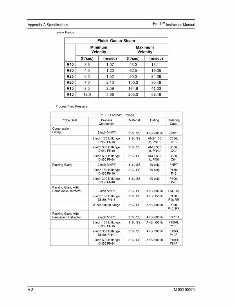
Linear Range
Fluid: Gas or Steam
Minimum Velocity
Maximum Velocity
(ft/sec) (m/sec) (ft/sec) (m/sec)
R40 3.5 1.07 43.0 13.11
R30 4.0 1.22 62.5 19.05
R25 5.0 1.52 80.0 24.38
R20 7.0 2.13 100.0 30.48
R15 8.5 2.59 134.6 41.03
R10 12.0 3.66 205.0 62.48 Process Fluid Pressure
Pro-T™ Pressure Ratings
Probe Seal Process Connection
Material Rating Ordering Code
Compression Fitting
2-inch MNPT
316L SS
ANSI 600 lb
CNPT
2-inch 150 lb flange, DN50 PN16
316L SS ANSI 150 lb, PN16
C150, C16
2-inch 300 lb flange, DN50 PN40
316L SS ANSI 300 lb, PN40
C300, C40
2-inch 600 lb flange, DN50 PN64
316L SS ANSI 600 lb, PN64
C600, C64
Packing Gland 2-inch MNPT 316L SS 50 psig PNPT
2-inch 150 lb flange, DN50 PN16
316L SS 50 psig P150, P16
2-inch 300 lb flange, DN50 PN40
316L SS 50 psig P300, P40
Packing Gland with Removable Retractor
2-inch MNPT
316L SS
ANSI 300 lb
PM, RR
2-inch 150 lb flange, DN50, PN16
316L SS ANSI 150 lb P150, P16,RR
2-inch 300 lb flange 316L SS ANSI 300 lb P300, P40, RR
Packing Gland with Permanent Retractor
2-inch MNPT
316L SS
ANSI 600 lb
PNPTR
2-inch 150 lb flange, DN50 PN16
316L SS ANSI 150 lb P150R, P16R
2-inch 300 lb flange, DN50, PN40
316L SS ANSI 300 lb P300R, P40R
2-inch 600 lb flange, DN50 PN64
316L SS ANSI 600 lb P600R, P64R
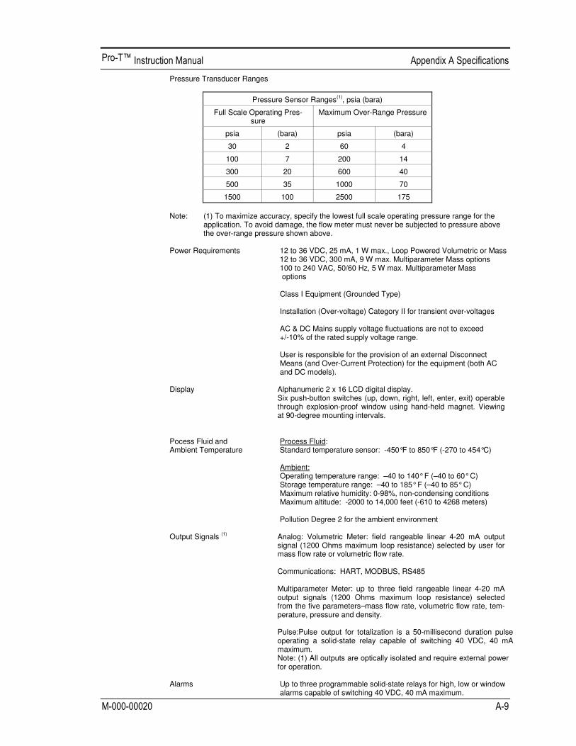
Pressure Transducer Ranges
Pressure Sensor Ranges(1), psia (bara)
Full Scale Operating Pres-sure
Maximum Over-Range Pressure
psia (bara) psia (bara)
30 2 60 4
100 7 200 14
300 20 600 40
500 35 1000 70
1500 100 2500 175
Note: (1) To maximize accuracy, specify the lowest full scale operating pressure range for the
application. To avoid damage, the flow meter must never be subjected to pressure above the over-range pressure shown above.
Power Requirements 12 to 36 VDC, 25 mA, 1 W max., Loop Powered Volumetric or Mass 12 to 36 VDC, 300 mA, 9 W max. Multiparameter Mass options 100 to 240 VAC, 50/60 Hz, 5 W max. Multiparameter Mass options Class I Equipment (Grounded Type) Installation (Over-voltage) Category II for transient over-voltages AC & DC Mains supply voltage fluctuations are not to exceed +/-10% of the rated supply voltage range. User is responsible for the provision of an external Disconnect
Means (and Over-Current Protection) for the equipment (both AC and DC models).
Display Alphanumeric 2 x 16 LCD digital display. Six push-button switches (up, down, right, left, enter, exit) operable
through explosion-proof window using hand-held magnet. Viewing at 90-degree mounting intervals.
Pocess Fluid and Process Fluid: Ambient Temperature Standard temperature sensor: -450°F to 850°F (-270 to 454°C) Ambient: Operating temperature range: –40 to 140° F (–40 to 60° C) Storage temperature range: –40 to 185° F (–40 to 85° C) Maximum relative humidity: 0-98%, non-condensing conditions Maximum altitude: -2000 to 14,000 feet (-610 to 4268 meters) Pollution Degree 2 for the ambient environment Output Signals (1) Analog: Volumetric Meter: field rangeable linear 4-20 mA output
signal (1200 Ohms maximum loop resistance) selected by user for mass flow rate or volumetric flow rate.
Communications: HART, MODBUS, RS485 Multiparameter Meter: up to three field rangeable linear 4-20 mA
output signals (1200 Ohms maximum loop resistance) selected from the five parameters–mass flow rate, volumetric flow rate, tem-perature, pressure and density.
Pulse:Pulse output for totalization is a 50-millisecond duration pulse
operating a solid-state relay capable of switching 40 VDC, 40 mA maximum.
Note: (1) All outputs are optically isolated and require external power for operation.
Alarms Up to three programmable solid-state relays for high, low or window
alarms capable of switching 40 VDC, 40 mA maximum.
Totalizer Based on user-determined flow units, six significant figures in scien-
tific notation. Total stored in non-volatile memory. Wetted Materials 316L stainless steel. 302 stainless steel. 17-4 PH stainless steel. Tungsten carbide. Sapphire Teflon® packing gland below 500° F (260° C). Graphite packing gland above 500° F (260° C). Enclosure Protection Classification NEMA 4X and IP66 cast enclosure. Electrical Ports Two 3/4-inch female NPT ports. Mounting Connections Permanent installation: 2-inch MNPT; 150, 300, 600 lb ANSI flange,
PN16, PN40, PN64 flange with compression fitting probe seal. Hot Tap(1) Installation: 2-inch MNPT; 150, 300, 600 lb ANSI flange,
PN16, PN40, PN64 flange and optional retractor with packing gland probe seal.
Note: (1) Removable under line pressure. Mounting Position Meter must be perpendicular within ± 5° of the pipe centerline. Certifications Material Certificate – US Mill certs on all pressure retaining parts Pressure Test Certificate Certificate of Conformance NACE Certification (MR0175) Approvals FM / FMC, ATEX, IECEX approvals pending

Pro-T Insertion Multivariable Mass
Turbine Flow Meter
V
VT
VTP
VT-EMS
VTP-EMS
SL Standard Length
CL Compact Length
EL Extended Length
L
R ( )
DD Digital Display and Programming Buttons
ND No Display
DCL
DCH
AC
1AHL
1AH
1AM
3AH
3AM
ST
MT
HT
P0
P1
P2
P3
P4
P5
Feature 9: Process Connections
CNPT Compression, 2 inch NPT PNPTR-EL Packing Gland, 2 inch NPT, Retractor (use w ith EL probe)
C150 Compression, 2 inch 150# Flange P150R Packing Gland, 2 inch 150# Flange, Retractor
C16 Compression, DN50 PN16 Flange P150R-EL Packing Gland, 2 inch 150# Flange, Retractor (EL probe)
C300 Compression, 2 inch 300# Flange P16R Packing Gland, DN50 PN16 Flange, Retractor
C40 Compression, DN50 PN40 Flange P16R-EL Packing Gland, DN50 PN16 Flange, Retractor (EL probe)
C600 Compression, 2 inch 600# Flange P300R Packing Gland, 2 inch 300# Flange, Retractor
C64 Compression, DN50 PN64 Flange P300R-EL Packing Gland, 2 inch 300# Flange, Retractor (EL probe)
PNPT Packing Gland*, 2 inch NPT P40R Packing Gland, DN50 PN40 Flange, Retractor
P150 Packing Gland*, 2 inch 150# Flange P40R-EL Packing Gland, DN50 PN40 Flange, Retractor (EL probe)
P16 Packing Gland*, DN50 PN16 Flange P600R Packing Gland, 2 inch 600# Flange, Retractor
P300 Packing Gland*, 2 inch 300# Flange P600R-EL Packing Gland, 2 inch 600# Flange, Retractor (EL probe)
P40 Packing Gland*, DN50 PN40 Flange P64R Packing Gland, DN50 PN64 Flange, Retractor
PNPTR Packing Gland, 2 inch NPT, Retractor P64R-EL Packing Gland, DN50 PN64 Flange, Retractor (EL probe)* One removable retractor must be o rdered if the process pressure is >50 psig.
R40
R30
R25
R20
R15
R10
Loop pow ered option - one analog output (4-20 mA), one alarm, one pulse, HART, DCL input pow er only
Feature 6: Output Signal
Feature 4: Dipsplay Option
Feature 3: Electronics Enclosure
Pro-T
Feature 5: Input Power
Volumetric Flow Meter for liquid, gas and steam
Velocity and Temperature Sensors
Remote Electronics NEMA 4X, IP66, Specify cable length in parentheses
Parent Number Code
Velocity, Temperature and Pressure Sensors
Energy output options
Energy options w ith Pressure Sensor
Feature 2: Probe Length
Feature 1 : Multivariable Options
NEMA 4X, IP66 Enclosure
One analog output (4-20 mA), one alarm, one pulse, MODBUS Communication Protocol, DCH or AC option only
Three analog outputs (4-20 mA), three alarms, one pulse, MODBUS (VT,VTP only), DCH or AC option only
Standard Temperature
Medium Temperature
Process temperature -60° to 400°F (-50° to 200°C)
Maximum 500 psia (34 bara), Proof 1000 psia (64 bara)
Process temperature -60° to 200°F (-50° to 95°C)
High Temperature
Maximum 100 psia (7 bara), Proof 200 psia (14 bara)
Three analog outputs (4-20 mA), three alarms, one pulse, HART (VT,VTP only), DCH or AC option only
Feature 7: Temperature Options
Maximum 30 psia (2 bara), Proof 60 psia (4 bara)
Process temperature -400 to 800°F (-240 to 425°C)
Feature 8: Pressure Options
Gas or Steam, Vuse = 7.0 ft/sec, Vmin = 23.1 f t/sec, Vmax = 100 ft/sec, 20° pitch
Gas or Steam, Vuse = 8.5 ft/sec, Vmin = 31.4 f t/sec, Vmax = 134.6 f t/sec, 15° pitch
Gas or Steam, Vuse = 12.0 f t/sec, Vmin = 47.8 f t/sec, Vmax = 205 f t/sec, 10° pitch
Model Number Information - Pro-TTM
Insertion Mass Turbine Flowmeter
Feature 10: Rotor Options
Gas or Steam, Vuse = 3.5 ft/sec, Vmin = 10 ft/sec, Vmax = 43 f t/sec, 40° pitch
Gas or Steam, Vuse = 4.0 ft/sec, Vmin = 14.6 f t/sec, Vmax = 62.5 ft/sec, 30° pitch
Gas or Steam, Vuse = 5.0 ft/sec, Vmin = 18.2 f t/sec, Vmax = 80 ft/sec, 25° pitch
One analog output (4-20 mA), one alarm, one pulse, HART Communication Protocol, DCH or AC option only
No Pressure Sensor
12-36 VDC, 25mA, 1W max. required on loop pow ered meters, 1AHL only
12-36 VDC, 300mA, 9W max. - use w ith 1AH, 1AM, 3AH, 3AM
100-240 VAC, 50/60 Hz line pow er, 5W max. - use w ith 1AH, 1AM, 3AH, 3AM
Maximum 1500 psia (100 bara), Proof 2500 psia (175 bara)
Maximum 300 psia (20 bara), Proof 600 psia (41 bara)

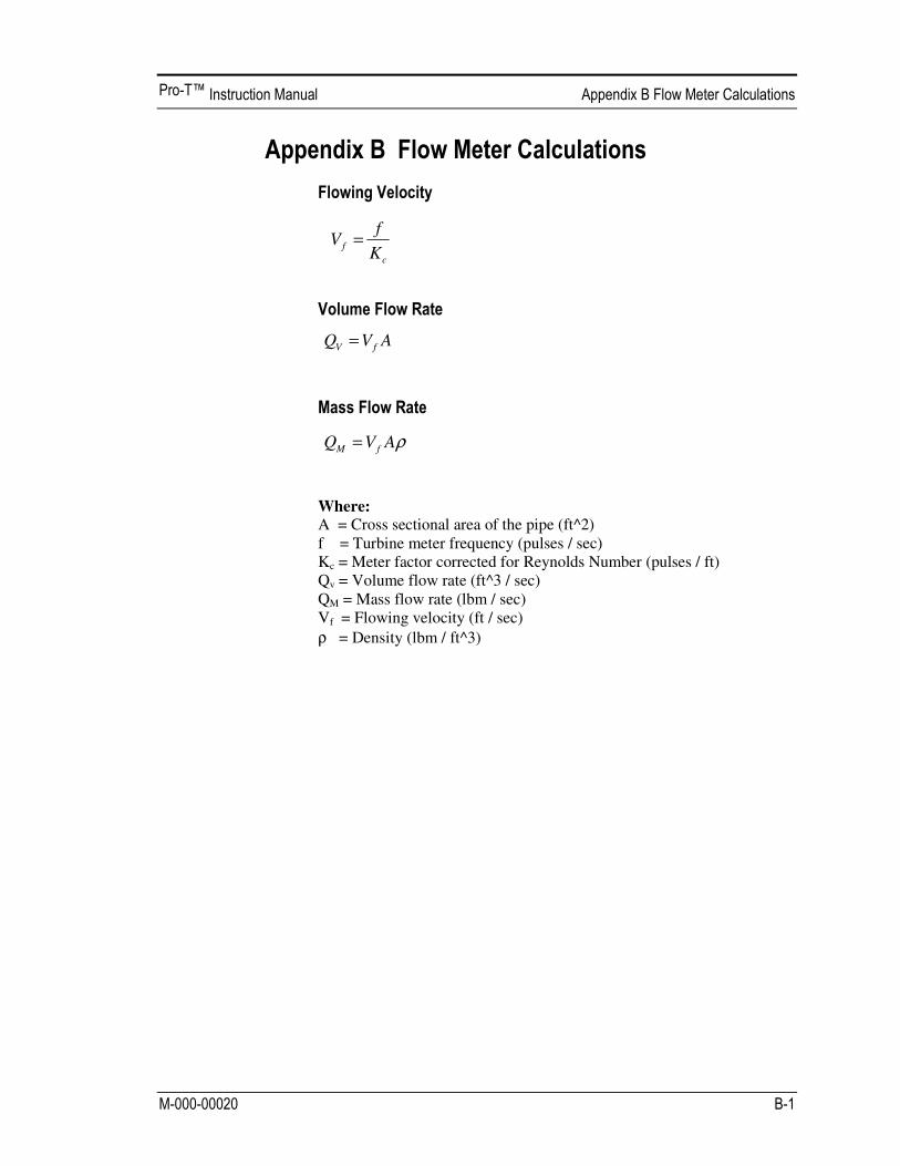
Where:
A = Cross sectional area of the pipe (ft^2) f = Turbine meter frequency (pulses / sec) Kc = Meter factor corrected for Reynolds Number (pulses / ft) Qv = Volume flow rate (ft^3 / sec) QM = Mass flow rate (lbm / sec) Vf = Flowing velocity (ft / sec)
! = Density (lbm / ft^3)
c
fK
fV =
AVQ fV =
!AVQ fM =

When “Steam T & P” is selected in the “Real Gas” selection of the Fluid Menu, the calculations are based on the equations below.
The density of steam is calculated from the formula given by Keenan and Keys. The given equation is for the volume of the steam.
Where tau is 1/ temperature in Kelvin. The density can be found from 1/(v/ standard density of water).
The viscosity is based on an equation given by Keenan and Keys.
Where T is the temperature in Kelvin
Bp
Tv +
•=
04.555.4
12123
13
033
2
4
01
2
00 )()()( pgBpgBpgBBB "#"+"+= $$$$$$280870
0 1062.264189.1 $$ ""#=B
251 106246.1546.82)( $$$ ""#"=g
252 102697.121828.0)( $$ ""#=g
246443 10768.610635.3)( $$ ""#"=
#g
T
Tpoise
/8.4461
10501.1)(
5
+
"=
#
%

Use this formula to determine the settings for “Real Gas; Gas” selections and “Other Gas” selections entered in the Fluid Menu. The calculations for gas were taken from Richard W. Miller, Flow Measurement Engi-neering Handbook (Third Edition, 1996).
The density for real gases is calculated from the equation:
Where G is the specific gravity, Mw is the molecular weight of
air, pf is the flowing pressure, Z is flowing compressibility, Ro is
the universal gas constant, and T is the flowing temperature.
The specific gravity, and Ro are known and are stored in a table used by the Turbine meter. The hard coefficient to find is the compressibility, Z. Z is found using the Redlich-Kwong Equation (Miller page 2-18). The Redlich-Kwong Equation uses the reduced temperature and pressure to calculate the compressibility factor. The equations are non linear and an iterative solution is used. The Turbine program uses Newton’s Me-thod on the Redlich-Kwong equations to iteratively find the compressi-bility factor. The critical temperature and pressure used in the Redlich-Kwong equation are stored in the fluid data table with the other coeffi-cients.
The viscosity for real gases is calculated using the exponential equation for two known viscosities. The equation is: Where a and n are found from two known viscosities at two temperatures.
and
ff
fAirw
TRZ
pGM
0
,=!
nKcP aT=µ
)/ln(
])/()ln[(
12
12
KK
cPcP
TTn
µµ=
n
K
cP
Ta
1
1)(µ=

Use this formula to determine the settings for “Goyal-Dorais” selections and “Other Liquid” selections entered in the Fluid Menu. The liquid cal-culations were taken from Richard W. Miller, Flow Measurement Engi-neering Handbook (Third Edition, 1996).
The liquid density is found using the Goyal-Doraiswamy Equation. Goy-al-Doraiswamy uses the critical compressibility, critical pressure and critical temperature, along with the molecular weight to find the density. The equation for specific gravity is: The specific gravity can then be converted into density.
The liquid viscosity is found by Andrade's equation. This uses two vis-cosities at different temperatures to extrapolate the viscosity. Andrade's equation:
To find A and B The temperatures are all in degrees Rankin. Do not believe the subscript R means they are reduced temperatures.
#=
C
f
cc
cF
T
T
ZT
MwpG 01102.0
008.0773.0
R
LL
T
BA
deg
exp=µ
1deg2deg
212deg1deg )/ln(
RR
RR
LTT
TTB
#=
µµ
)/exp( 1deg
1
RL
LTB
Aµ
=

A Cross sectional area. ACFM Actual Cubic Feet Per Minute (volumetric flow rate). ASME American Society of Mechanical Engineers. BTU British Thermal Unit, an energy measurement. Cenelec European Electrical Code. Compressibility A factor used to correct for the non-ideal changes in Factor a fluid’s density due to changes in temperature
and/or pressure. CSA Canadian Standards Association. D Diameter of a flow channel.
f Frequency generated by a turbine flow meter, usually in Hz. Flow Channel A pipe, duct, stack, or channel containing flowing fluid. Flow Profile A map of the fluid velocity vector (usually non-
uniform) in a cross-sectional plane of a flow channel (usually along a diameter).
FM Factory Mutual. Ft Foot, 12 inches, a measure of length. Ft^2 Square feet, measure of area. Ft^3 Cubic feet, measure of volume. GPM Gallons Per Minute. Hz Hertz, cycles per second.
Insertion Flow Meter A flow meter which is inserted into a hole in the us-
er’s pipeline. Joule A unit of energy equal to one watt for one second. Al-
so equal to a Newton-meter.

LCD Liquid crystal display.
m Mass flow rate.
mA Milli-amp, one thousandth of an ampere of current. µ Viscosity, a measure of a fluid’s resistance to shear stress.
Honey has high viscosity, alcohol has low viscosity.
!P Permanent pressure loss.
P Line pressure (psia or bar absolute).
" act The density of a fluid at the actual temperature and pressure operating conditions.
" std The density of a fluid at standard conditions (usually 14.7 psia and 20° C).
Permanent Unrecoverable drop in pressure. Pressure Loss Pitch The angle of the blades of a turbine rotor. PRTD An resistance temperature detector (RTD) with plati-
num as its element. Used because of high stability. psia Pounds per square inch absolute (equals psig + atmospheric pressure). Atmospheric
pressure is typically 14.696 psi at sea level. psig Pounds per square inch gauge.
PV Liquid vapor pressure at flowing conditions (psia or bar absolute).
Q Flow rate, usually volumetric. Rangeability Highest measurable flow rate divided by the lowest
measurable flow rate. Reynolds Number A dimensionless number equal to the density of a fluid or Re times the velocity of the fluid times the diameter of the
fluid channel, divided by the fluid viscosity (i.e., Re = "VD/µ). The Reynolds number is an important num-ber for turbine flow meters because it is used to de-termine the minimum measurable flow rate. It is the

ratio of the inertial forces to the viscous forces in a flowing fluid.
Rotor The velocity sensing element of a turbine flow meter.
Rotors are manufactured with the blades at a certain pitch. The pitch of the rotor blades determine the maximum velocity the turbine flow meter can be used in.
RTD Resistance temperature detector, a sensor whose
resistance increases as the temperature rises. scfm Standard cubic feet per minute (flow rate converted
to standard conditions, usually 14.696 psia and 68° F).
Totalizer An electronic counter which records the total accu-
mulated flow over a certain range of time. Traverse The act of moving a measuring point across the
width of a flow channel.
Uncertainty The closeness of agreement between the result of a
measurement and the true value of the measurement. V Velocity or voltage. VAC Volts, alternating current. VDC Volts, direct current.