turbomachinery machines 15me53.pdf · 2020-03-28 · definition of a turbo machine a turbo machine...
TRANSCRIPT

TRINITY INSTITUTE OF TECHNOLOGY
AND RESEARCH
BHOPAL
TURBOMACHINERY
NOTES
B.TECH VI SEM
TURBOMACHINE NOTES
TURBO MACHINES
Introduction: Definition of turbo machine, parts of turbo machines, Comparison
with positive displacement machines, Classification, Dimensionless parameters and
their significance, Effect of Reynolds number, Unit and specific quantities, model
studies. (Note: Since dimensional analysis is covered in Fluid Mechanics subject,
questions on dimensional analysis may not be given. However, dimensional
parameters and model studies may be given more weightage.)
Thermodynamics of fluid flow: Application of first and second law of
thermodynamics to turbo machines, Efficiencies of turbo machines, Static and
Stagnation states, Incompressible fluids and perfect gases, overall isentropic
efficiency, stage efficiency (their comparison) and polytropic efficiency for both
compression and expansion processes. Reheat factor for expansion process. expansion process
Energy exchange in Turbo machines: Euler’s turbine equation, Alternate form of
Euler’s turbine equation, Velocity triangles for different values of degree of
reaction, Components of energy transfer, Degree of Reaction, utilization factor,
Relation between degree of reaction and Utilization factor, Problems.
General Analysis of Turbo machines: Radial flow compressors and pumps –
general analysis, Expression for degree of reaction, velocity triangles, Effect of
blade discharge angle on energy transfer and degree of reaction, Effect of blade
discharge angle on performance, Theoretical head – capacity relationship, General
analysis of axial flow pumps and
compressors, degree of reaction, velocity triangles, Problems
Steam Turbines: Classification, Single stage impulse turbine, condition for
maximum blade efficiency, stage efficiency, Need and methods of compounding,
Multi-stage impulse turbine, expression for maximum utilization factor.
Reaction turbine – Parsons’s turbine, condition for maximum utilization factor,
reaction staging. Problems. 10 Hours
Hydraulic Turbines: Classification, various efficiencies. Pelton turbine – velocity
triangles, design parameters, Maximum efficiency. Francis turbine - velocity
triangles, design parameters, runner shapes for different blade speeds. Draft tubes-
Types and functions. Kaplan and Propeller turbines – velocity triangles, design
parameters. Problems.
Centrifugal Pumps: Classification and parts of centrifugal pump, different heads
and efficiencies of centrifugal pump, Minimum speed for starting the flow,
Maximum suction lift, Net positive suction head, Cavitation, Need for priming,
Pumps in series and parallel. Problems.
Centrifugal Compressors: Stage velocity triangles, slip factor, power input factor,
Stage work, Pressure developed, stage efficiency and surging and problems. Axial
flow Compressors: Expression for pressure ratio developed in a stage, work done
factor, efficiencies and stalling. Problems

TEXT BOOKS:
1. An Introduction to Energy Conversion, Volume III, Turbo machinery, V.
Kadambi and Manohar Prasad, New Age International Publishers, reprint 2008.
2. Turbines, Compressors & Fans, S. M. Yahya, Tata McGraw Hill Co. Ltd., 2nd edition, 2002
3. Turbomachines, B. U Pai , Wiley First Edition 2013.
REFERENCES
Principals of Turbo machines, D. G. Shepherd, The Macmillan Company (1964).
1. Fluid Mechanics & Thermodynamics of Turbo machines, S. L. Dixon, Elsevier (2005).
2. Turbo machine, B.K.Venkanna PHI, New Delhi 2009.
3. Text Book of Turbo machines, M. S. Govindgouda and A. M. Nagaraj, M. M.
Publications, 4Th Ed, 2008.
MODULE: 1
INTRODUCTION
Definition of a Turbo machine
A turbo machine is a device in which energy transfer occurs between a flowing fluid and
rotating element due to dynamic action. This results in change of pressure and momentum of the fluid.
Parts of a turbo machine
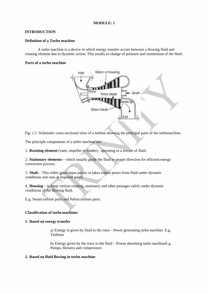
Fig: 1.1. Schematic cross-sectional view of a turbine showing the principal parts of the turbomachine.
The principle components of a turbo machine are:
1. Rotating element (vane, impeller or blades)– operating in a stream of fluid.
2. Stationary elements – which usually guide the fluid in proper direction for efficient energy
conversion process.
3. Shaft – This either gives input power or takes output power from fluid under dynamic
conditions and runs at required speed.
4. Housing – to keep various rotating, stationery and other passages safely under dynamic
conditions of the flowing fluid.
E.g. Steam turbine parts and Pelton turbine parts.
Classification of turbo machines
1. Based on energy transfer
a) Energy is given by fluid to the rotor - Power generating turbo machine E.g.
Turbines
b) Energy given by the rotor to the fluid – Power absorbing turbo machineE.g.
Pumps, blowers and compressors
2. Based on fluid flowing in turbo machine
a) Water
b) Air
c) Steam
d) Hot gases
e) Liquids like petrol etc.
3. Based on direction of flow through the impeller or vanes or blades, with reference to the
axis of shaft rotation
a) Axial flow – Axial pump, compressor or turbine
b) Mixed flow – Mixed flow pump, Francis turbine
c) Radial flow – Centrifugal pump or compressor
d) Tangential flow – Pelton water turbine
4. Based on condition of fluid in turbo machine
a) Impulse type (constant pressure) E.g. Pelton water turbine
b) Reaction type (variable pressure) E.g. Francis reaction turbines
5. Based on position of rotating shaft a)
Horizontal shaft – Steam turbines
b) Vertical shaft – Kaplan water turbines c)
Inclined shaft – Modern bulb micro
Comparison between positive displacement machines andTurbo machines
Comparison between positive displacement machines andTurbo machines
Turbo machines Positive displacement machines
It creates Thermodynamic & Dynamic It creates Thermodynamic &Mechanical
action b/w rotating element & flowing fluid, action b/w moving member&static fluid,
energy transfer takes place if pressure and energy transfer takes place with displacement
momentum changes of fluid
It involves a steady flow of fluid & rotating It involves a unsteady flow of fluid &
motion of mechanical element reciprocating motion
They operate at high rotational speed They operate at low speed
Change of phase during fluid flow causes Change of phase during fluid flow causes
serious problems in turbomachine less problems in Positive displacement machines
Efficiency is usually less Efficiency is higher
It is simple in design It is complex in design
Due to rotary motion vibration problems are Due to reciprocating motion vibration
less problems are more
E.g. Hydraulic turbines, Gas turbines, Steam E.g. I.C engines, Reciprocating air
turbines etc. compressor, pumps etc.

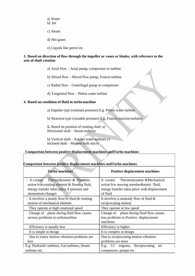
Effect of Reynolds Number
Just like flow in pipes with friction, with decreasing Reynolds number, the loss factor
increases at first slowly, thenmore and more rapidly in Turbo machines.
The majority of ordinary turbo machines, (handling water, air, steam or gas) are found to operate in
fully rough region.
The critical Reynolds number, at which the flow becomes fully rough, varies with the size of the
machine (it dependson relative roughness) and its exact location for a given machine is difficult to
predict.
The understanding of boundary layer and its separation is of importance in losseffects. The graph
shows the loss factor in head and efficiency of a moderate size centrifugal pump
Unit Quantities
Unit quantities are unit flow, unit power and unit speed which are under considerations of unit
meter in connection with hydraulic turbines. In other words, the unit quantities are defined for the
head of 1m.


Dimensionless groups and their significance
The Performance of a turbomachine like pumps, water turbines, fans or blowers for incompressible
flow can beexpressed as a function of:
(i) Density of the fluid
(ii) Speed of the rotor N
(iii) Characteristic diameter D
(iv) Discharge Q
(v) Gravity head (gH)
(vi) Power developed P and
(vii) Viscosity μ.
Obtain dimensionless groups and explain their significance.
Solution
Using Buckingham p theorem
Turbo machine = f [ , N, D, Q, gH, P, μ]
Performance
Taking N, D as repeating variables and grouping with other variables as non dimensional groups
The above equation is the specific speedequation foe a turbine. It is defined as a “speed of a
geometrically similar machine which produces 1 KW power under a head of 1m”
Application of First and Second Laws to Turbo Machines
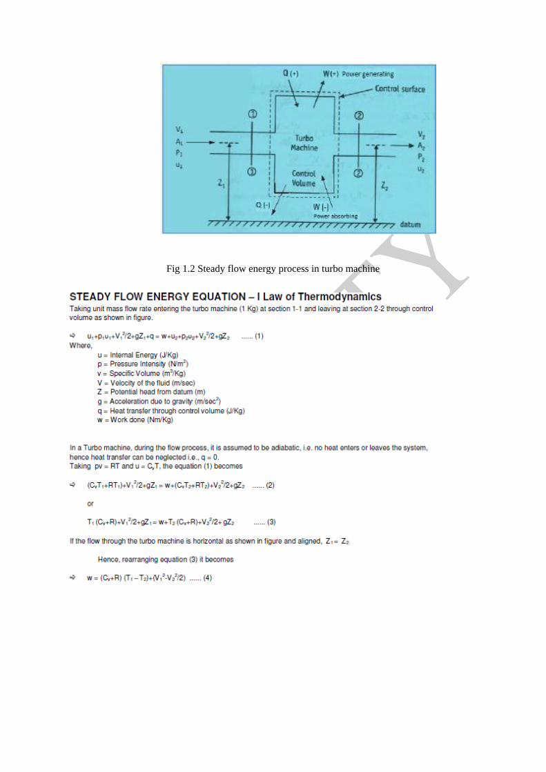
Fig 1.2 Steady flow energy process in turbo machine
THERMODYNAMICS OF FLUID FLOW
Static and Stagnation states
Turbomachines involve the use of compressible and incompressible fluids. In compressible
TM’s fluid move with velocities more than Mach one at many locations. In incompressible TM’s the
fluid velocities are generally low, however, K.E. and P.E. of the moving fluid are very large and
cannot be neglected To formulate equations based on actual state of the fluid based on laws of
thermodynamics two states are used.
The states are static state and stagnation states.
Static State
If the measuring instrument is static with respect to the fluid, the measuredquantity is known
as static property. The measured static property could bepressure, velocity temperature, enthalpy etc.
The state of the particle fixed by aset of static properties is called static state.
Stagnation State
It is defined as the terminal state of a fictitious, isentropic work-free and steadyflow process during
which the final macroscopic P.E. and K.E. of the fluid particleare reduced to zero.
Real process does not lead to stagnation state because no real process isisentropic. Stagnation
property changes provide ideal value against which the realmachine performance can be compared. It
is possible to obtain stagnationproperties in terms of static properties by using the definition of
stagnation state.Consider the steady flow process given by the first law of thermodynamics.

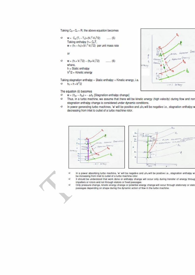
The adiabatic efficiency of a TM can be calculated from the h-s diagram for both the expansion and
compression process. The ideal using work input or output can be using either static or stagnation
states.
(a) Power Generating Turbomachines (PGTM)
Actual work output for PGTM= ℎ01 − ℎ02
The proper equation is determined by the conditions of Turbomachine in question.
For example in a turbine if the inlet Ke is negligible and exit Ke is used forproduction of mechanical
energy somewhere else, then static to total definition isused. If the exit Ke is wasted then static to
static definition is used.
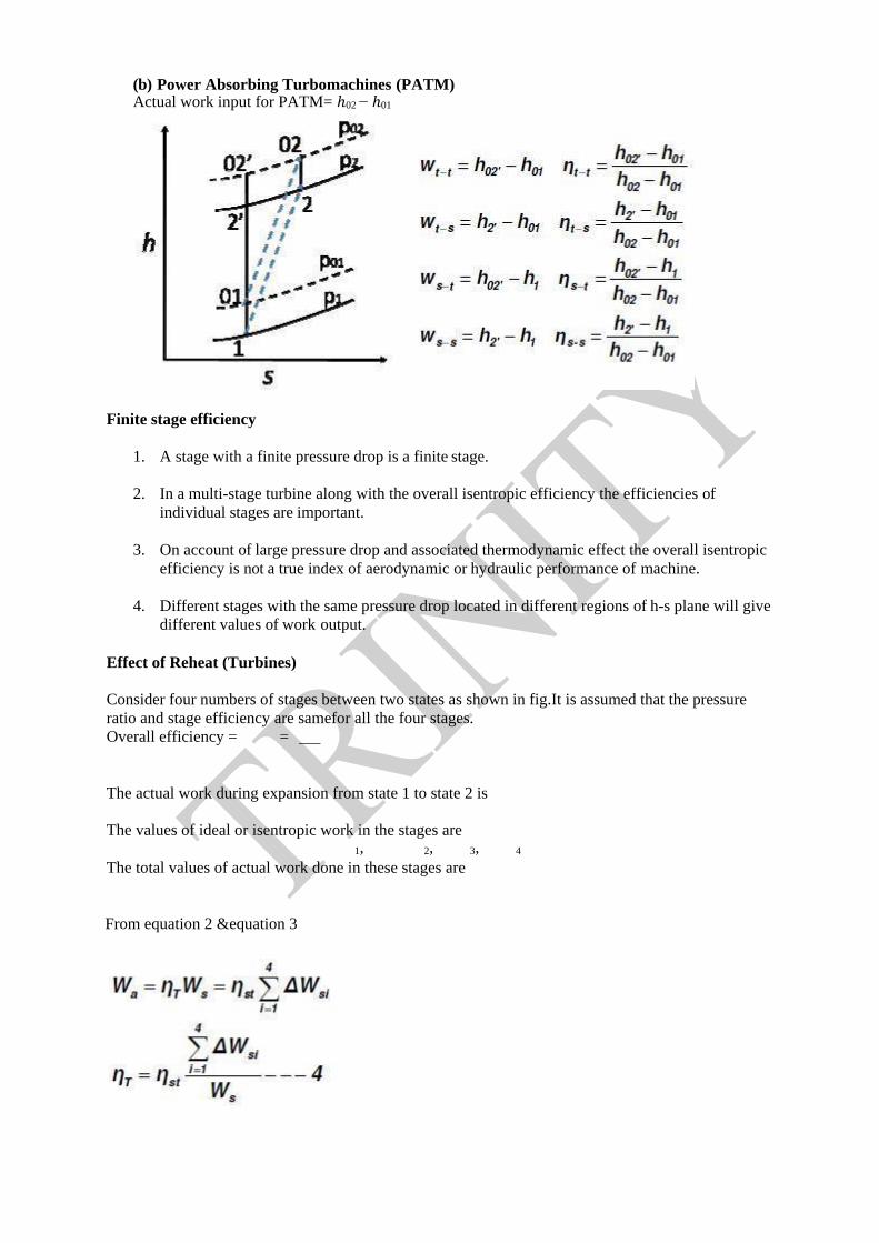
(b) Power Absorbing Turbomachines (PATM) Actual work input for PATM= ℎ02 − ℎ01
Finite stage efficiency
1. A stage with a finite pressure drop is a finite stage.
2. In a multi-stage turbine along with the overall isentropic efficiency the efficiencies of
individual stages are important.
3. On account of large pressure drop and associated thermodynamic effect the overall isentropic
efficiency is not a true index of aerodynamic or hydraulic performance of machine.
4. Different stages with the same pressure drop located in different regions of h-s plane will give
different values of work output.
Effect of Reheat (Turbines)
Consider four numbers of stages between two states as shown in fig.It is assumed that the pressure
ratio and stage efficiency are samefor all the four stages.
Overall efficiency = =
The actual work during expansion from state 1 to state 2 is
The values of ideal or isentropic work in the stages are
1, 2, 3, 4
The total values of actual work done in these stages are
From equation 2 &equation 3

Infinitesimal stage efficiency or Polytropic efficiency(Turbines)
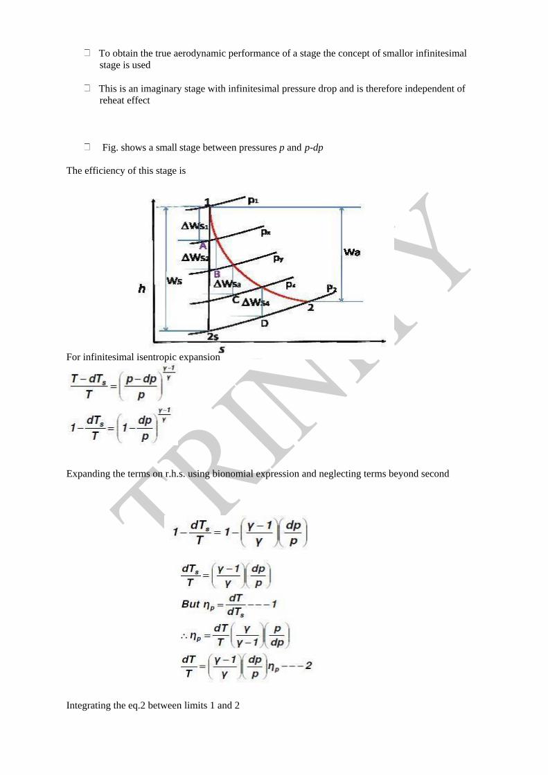
To obtain the true aerodynamic performance of a stage the concept of smallor infinitesimal
stage is used
This is an imaginary stage with infinitesimal pressure drop and is therefore independent of
reheat effect
Fig. shows a small stage between pressures p and p-dp
The efficiency of this stage is
For infinitesimal isentropic expansion
Expanding the terms on r.h.s. using bionomial expression and neglecting terms beyond second
Integrating the eq.2 between limits 1 and 2

The irreversible adiabatic (actual) expansion process can be considered as equivalent to a
polytropic process with index n.
The index of expansion in actual process is
When ηp=1, n=γ the expansion line coincides with the isentropic expansion. The efficiency of a
finite stage can now be expressed in terms of small stage efficiency. Taking static values of Tand p
and assuming perfect gas

Equations 7 and 8 can give the efficiencies of various finite expansion processes with different values
of pressure ratio and small stage efficiency
Finite stage efficiency (Compressor)
A compressor with a finite pressure rise is known as a finite stage
Stage work is a function of initial temperature and pressure ratio
For the same pressure ratio, a stage requires a higher value of work with higher temperature
Thus compressor stages in the higher temperature region suffer on account of this The
above factors have a cumulative effect on the efficiency of multistage compressor
Effect of preheat (Compressor)
Consider a compressor with four stages as shown. It is assumed that all the stages have the same
efficiencies and pressure ratios.
The overall efficiency of the compressor is = WS⁄Wa
This makes the overall efficiency of the compressor smaller than stage efficiency
<
This is due to the thermodynamic effect called pr-heating the gas is not intentionally heated(
preheated) at the end of each compression stage.Thepreheat in small constant pressure processes is
only an internal phenomena and the compression process still remains an adiabatic process.

Infinitesimal or Polytropic Efficiency (Compressor)

A finite compressor stage can be made up of infinite number of small stages
Each of these infinitesimal stages have an efficiency efficiency or infinitesimal stage
efficiency
It is independent of thermodynamic effect and is therefore the aerodynamic performance of
the compressor
Consider a stage in which air is compressed from state 1 to state 2. It also shows an infinite
stage operating between pressures +
Substituting the value of dTs into equation 1

Integrating eq.2 between state 1 to 2
Assuming the irreversible adiabatic compression as equivalent to a polytropic process with index n,
equation 3 can be written as
The efficiency of finite compressor stage can be related to small stage efficiency. The actual
temperature rise is given by

Module: 2
ENERGY EXCHANGE IN TURBOMACHINES
Euler’s turbine equation

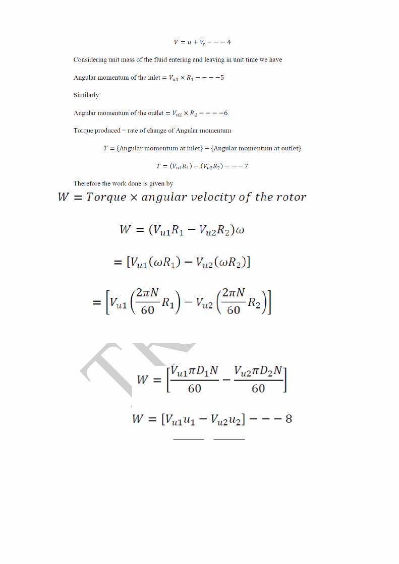

Alternate form of Euler’s turbine equation
Inlet and Outlet Velocity Triangles
Referring to velocity triangles
1 – Inlet, 2 – outlet
V1 = Absolute velocity of the fluid at inlet (before entering the rotor vanes)
Vr1 = Relative velocity of the fluid at rotor inlet
Vu1 = Tangential component of absolute velocity
OR
Whirl component of velocity at inlet
Vf1 = Flow component of absolute velocity at inlet
Vru1 = Whirl component of relative velocity at inlet
U1 = Linear rotor vane velocity at inlet
1= Absolute jet angle at inlet
1 = Vane (blade) angle at inlet
Referring to outlet velocity triangle
2 – Outlet
V2 = Absolute velocity of the fluid at outlet after leaving the rotorvanes.

Vr2 = Relative velocity of the fluid rotor outlet (Just about to leavethe rotor)
Vu2 = Whirl component of absolute velocity at outlet
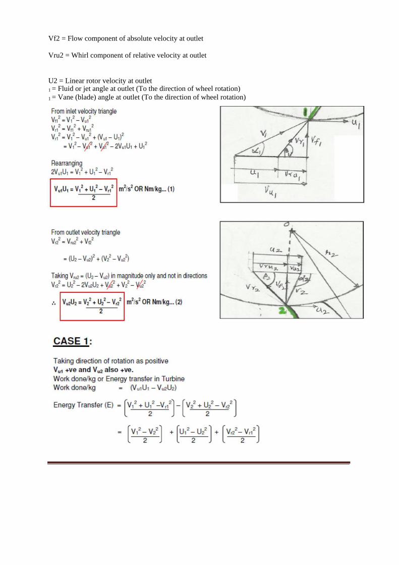
Vf2 = Flow component of absolute velocity at outlet
Vru2 = Whirl component of relative velocity at outlet
U2 = Linear rotor velocity at outlet
1 = Fluid or jet angle at outlet (To the direction of wheel rotation)
1 = Vane (blade) angle at outlet (To the direction of wheel rotation)

Degree of Reaction R
Degree of Reaction R is the ratio of Energy Transfer due toStatic Enthalpy change to Total
Energy Transfer due to Total Enthalpy change in a rotor.
∆h

When S = Static energy felt by rotor
KE = Kinetic energy change in rotor (in terms of V1 and V2, Absolute velocities)
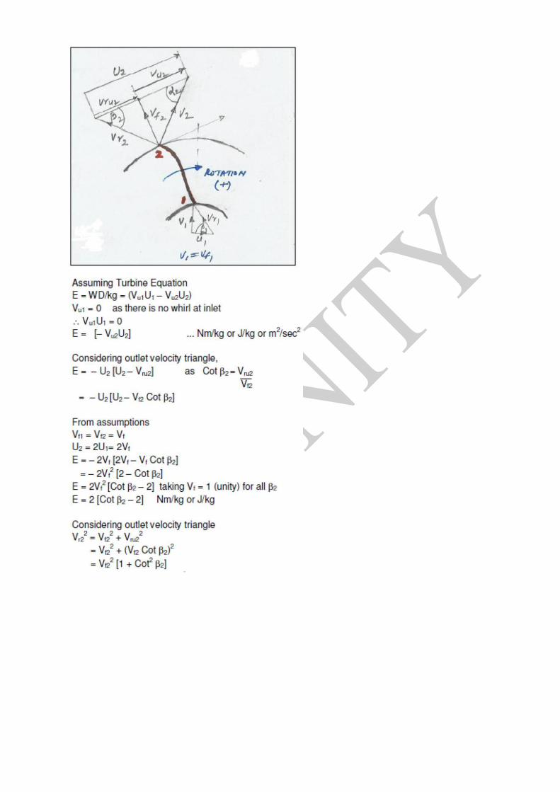
Effect of Blade Discharge Angle on Energy Transfer E and Degree of Reaction R
Consider an outward radial flow turbo machine as shown in figure, where 1 is inlet, 2 is
outlet
Assumptions
1) Radial velocity of flow is constant, i.e.
Vf1 = Vf2 = Vf
2) No whirl component at inlet
Vu1 = 0
3) Diameter at outlet is twice as at inlet, i.e.
D2 = 2D1or U2 = 2U1
4) Blade angle at inlet = 450, V1= Vf1= U1
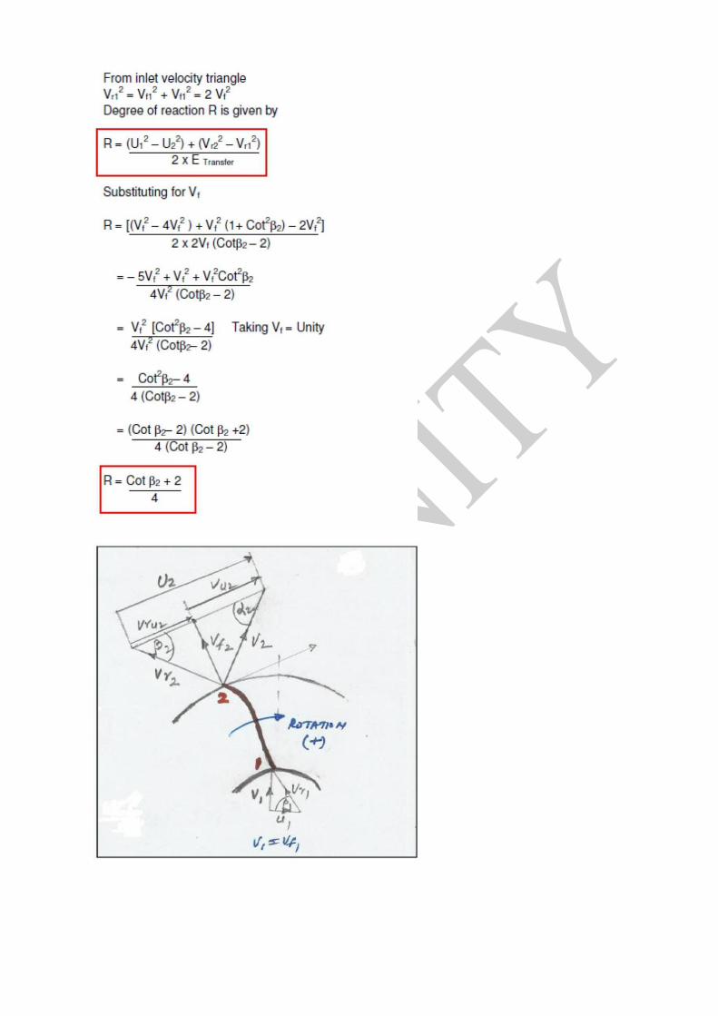

Degree of Reaction R
From velocity triangle at outlet for various
1. When b2 < 900 backward curves vane
Vu2 < U2
R < 1 > 0.5
2. For Radial blades b2 = 900
Vu2 = U2
R = 1 – ½ = 0.5
3. For forward curved vanes b2 > 900
Vu2 > U2
R < 0.5
GENERAL ANALYSIS OF TURBOMACHINES
Axial flow compressors and pumps
Axial flow compressors and pumps are power absorbing turbomachines. These machines
absorb external power and thereby increase the enthalpy of the flowing fluid. Axial flow
turbomachines use large quantity of fluid compared to mixed and centrifugal type of turbomachines.
However, the pressure rise per stage is lower in case of axial flow turbomachines than mixed and
centrifugal flow turbomachines. Axial flow compressors are used in aircraft engines, stand alone
power generationunits, marine engines etc.
Design of axial flow compressors is more critical than the design of turbines(power
generating turbomachines). The reason is that, in compressors the flowmoves in the direction of
increasing pressure (adverse pressure gradient). If theflow is pressurized by supplying more power,
the boundary layers attached to theblades and casing get detached and reverse flow starts which lead
to flowinstability leading to possible failure of the machine. However, in turbines the fluidmoves in
the decreasing pressure (favorable pressure gradient). To transfer agiven amount of energy more
number of stages is required in compressors than inturbines. Generally, the fluid turning angles are
limited to 20˚ in compressors andare 150˚ to 165˚ in case of turbines. Thus the pressure rise per stage
is limited incase of compressors. Fluid flows in direction of increasing pressure, this increasesthe
density of the fluid, and thus the height of the blade decreases from the entranceto the exit. Axial flow
compressors have inlet guide vanes at the entrance anddiffuser at the exit.
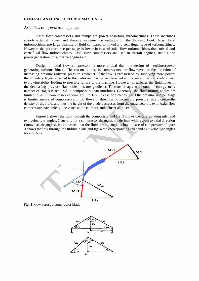
Figure 1 shows the flow through the compressor and fig. 2 shows thecorresponding inlet and
exit velocity triangles. Generally for a compressor theangles are defined with respect to axial direction
(known as air angles). It can beseen that the fluid turning angle is low in case of compressors. Figure
3 shows theflow through the turbine blade and fig. 4 the corresponding inlet and exit velocitytriangles
for a turbine.
Fig. 1 Flow across a compressor blade

Fig. 2 Inlet and exit velocity triangles
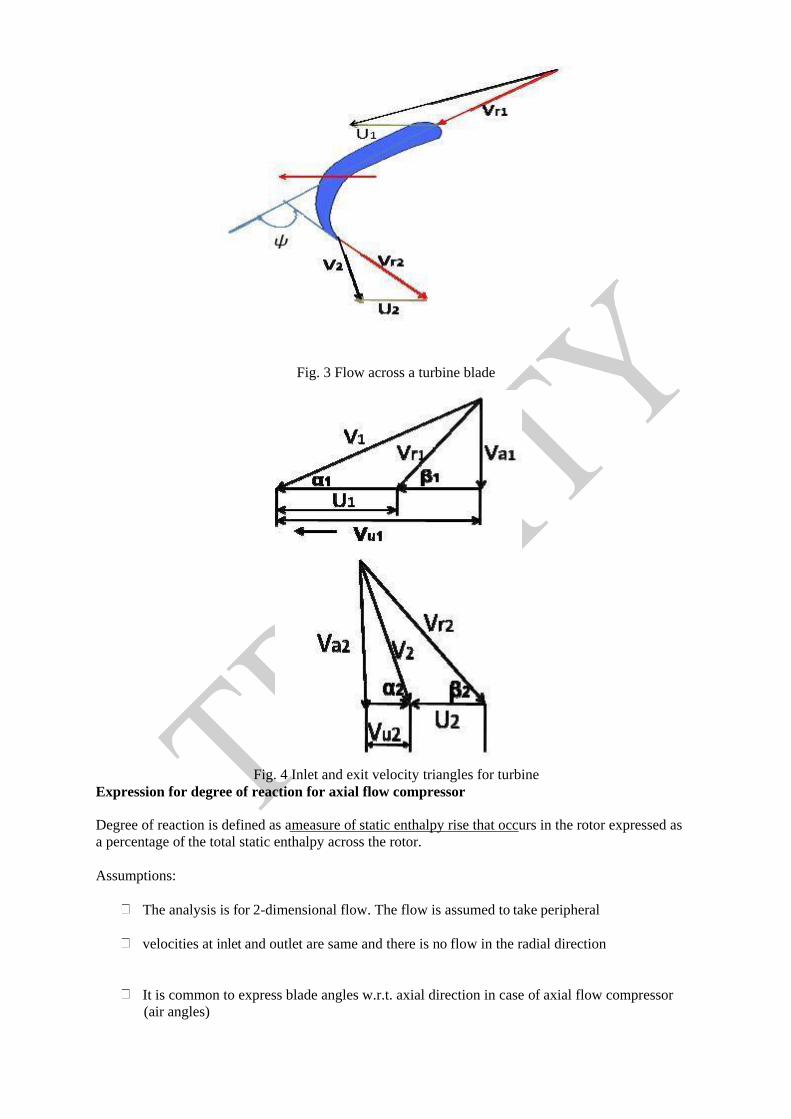
Fig. 3 Flow across a turbine blade
Fig. 4 Inlet and exit velocity triangles for turbine
Expression for degree of reaction for axial flow compressor
Degree of reaction is defined as a measure of static enthalpy rise that occurs in the rotor expressed as
a percentage of the total static enthalpy across the rotor.
Assumptions:
The analysis is for 2-dimensional flow. The flow is assumed to take peripheral
velocities at inlet and outlet are same and there is no flow in the radial direction
It is common to express blade angles w.r.t. axial direction in case of axial flow compressor
(air angles)

Axial velocity is assumed to remain constant

Figure 2 shows the inlet and exit velocity triangles for axial flow compressors. The
work done on the compressor = change in stagnation enthalpy
For an axial flows TM, from inlet velocity triangle
Similar from the exit velocity triangle
Equating equ. 2 and equ 3 and simplifying
Substuting eq. 6 and eq.7 in eq. 5
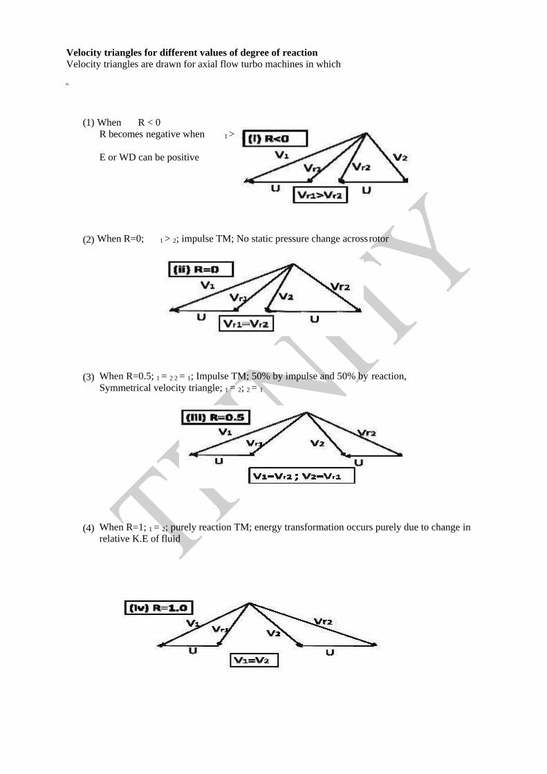
Velocity triangles for different values of degree of reaction
Velocity triangles are drawn for axial flow turbo machines in which
=
(1) When R < 0
R becomes negative when 1 >
E or WD can be positive
(2) When R=0; 1 > 2; impulse TM; No static pressure change across rotor
(3) When R=0.5; 1 = 2 2 = 1; Impulse TM; 50% by impulse and 50% by reaction, Symmetrical velocity triangle; 1 = 2; 2 = 1
(4) When R=1; 1 = 2; purely reaction TM; energy transformation occurs purely due to change in relative K.E of fluid
2
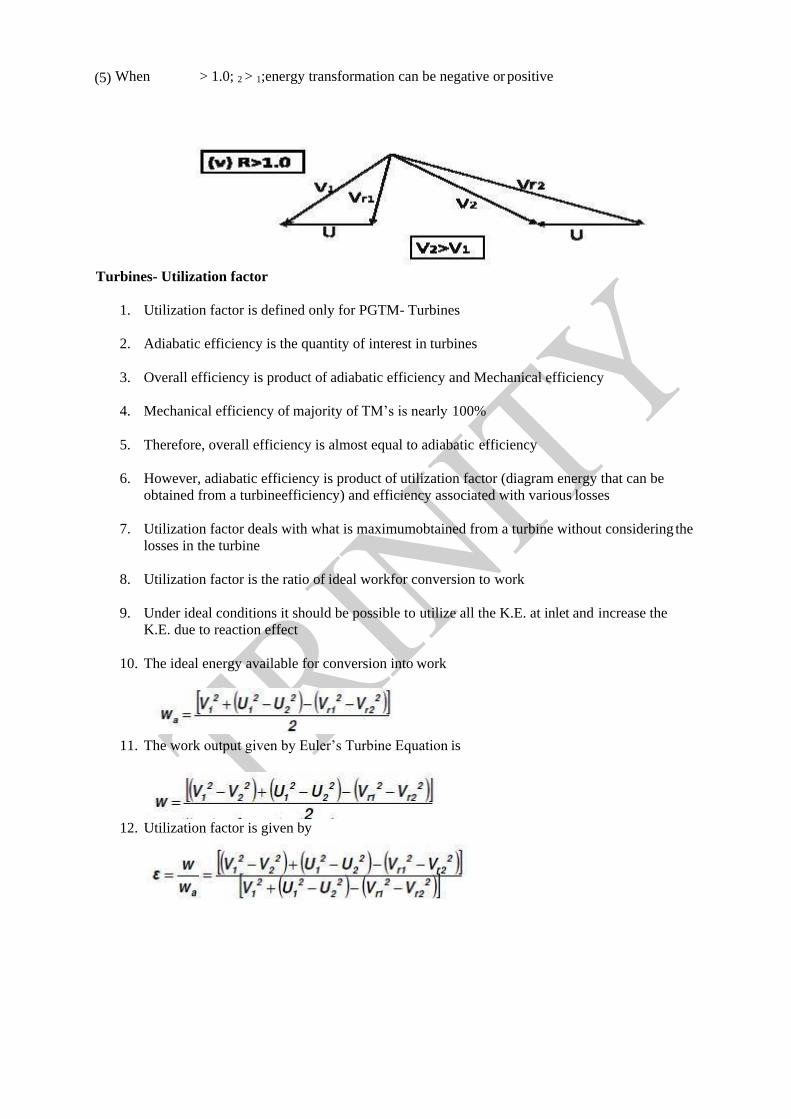
(5) When > 1.0; 2 > 1;energy transformation can be negative or positive
Turbines- Utilization factor
1. Utilization factor is defined only for PGTM- Turbines
2. Adiabatic efficiency is the quantity of interest in turbines
3. Overall efficiency is product of adiabatic efficiency and Mechanical efficiency
4. Mechanical efficiency of majority of TM’s is nearly 100%
5. Therefore, overall efficiency is almost equal to adiabatic efficiency
6. However, adiabatic efficiency is product of utilization factor (diagram energy that can be
obtained from a turbineefficiency) and efficiency associated with various losses
7. Utilization factor deals with what is maximumobtained from a turbine without considering the
losses in the turbine
8. Utilization factor is the ratio of ideal workfor conversion to work
9. Under ideal conditions it should be possible to utilize all the K.E. at inlet and increase the
K.E. due to reaction effect
10. The ideal energy available for conversion into work
11. The work output given by Euler’s Turbine Equation is
12. Utilization factor is given by
13. Utilization factor for modern TM’s is between 90% to 95%
Relation between utilization factor and degree of reaction
Utilization factor is given by
The degree of reaction is given by
Substituting the value of X in the expression for utilization factor andsimplifying
The above equation is valid for single rotor under the conditions where Euler’s turbine equations are
valid. The above equation is invalid when R = 1. The above equation is valid in the following range of
R = 0 ≤ R < 1.
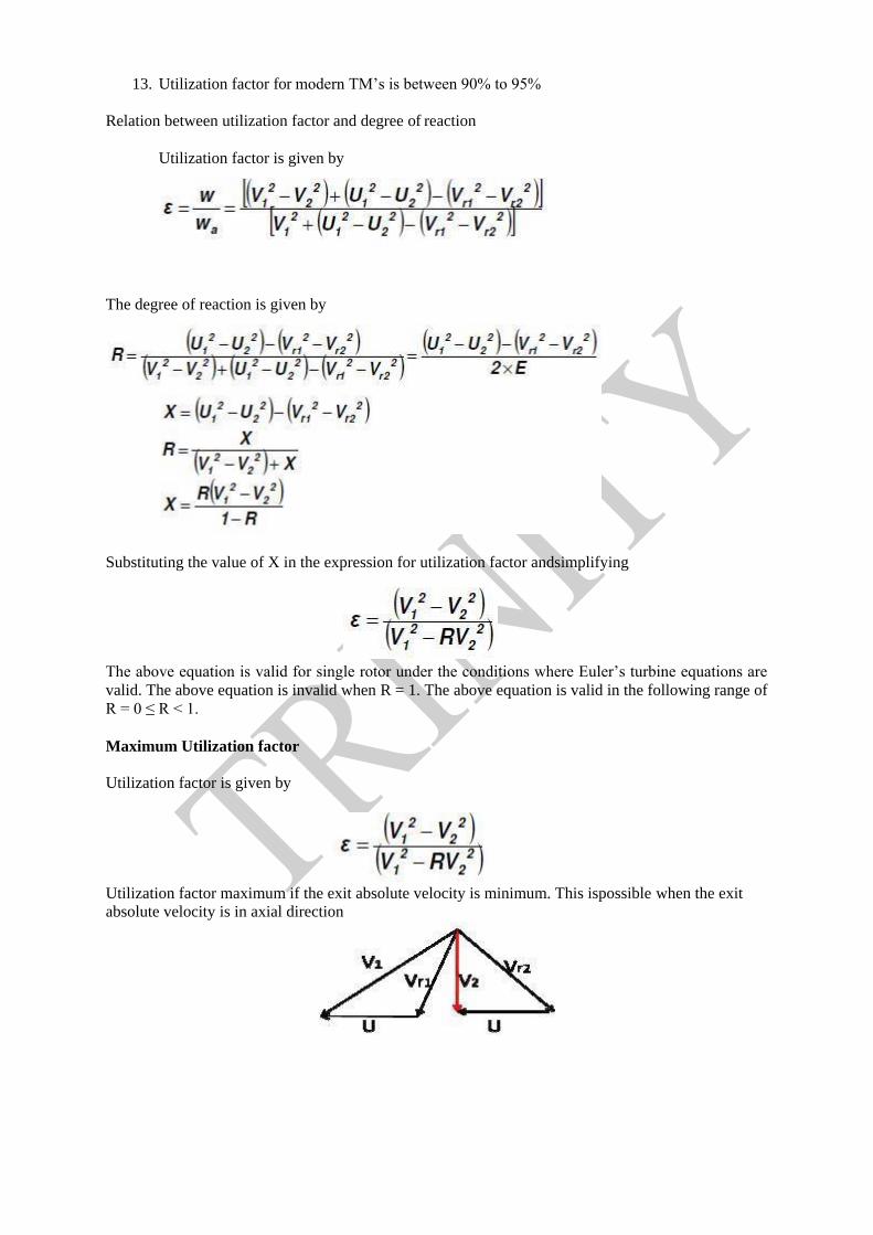
Maximum Utilization factor
Utilization factor is given by
Utilization factor maximum if the exit absolute velocity is minimum. This ispossible when the exit
absolute velocity is in axial direction

Maximum utilization factor is given by
Maximum Utilization factor for impulse turbine
For an impulse turbine R = 0,thus = 2 × 1
From the velocity triangles OAB and OBD aresimilar.
Thus AB = U
1is made as small as possible(150 200)
Maximum Utilization factor for 50% reaction turbines
50% reaction turbines have; 1 = 2 2 = 1; 1 = 2; 2 = 1and for maximum utilization 2 must be in axial
direction. The corresponding velocity triangles are
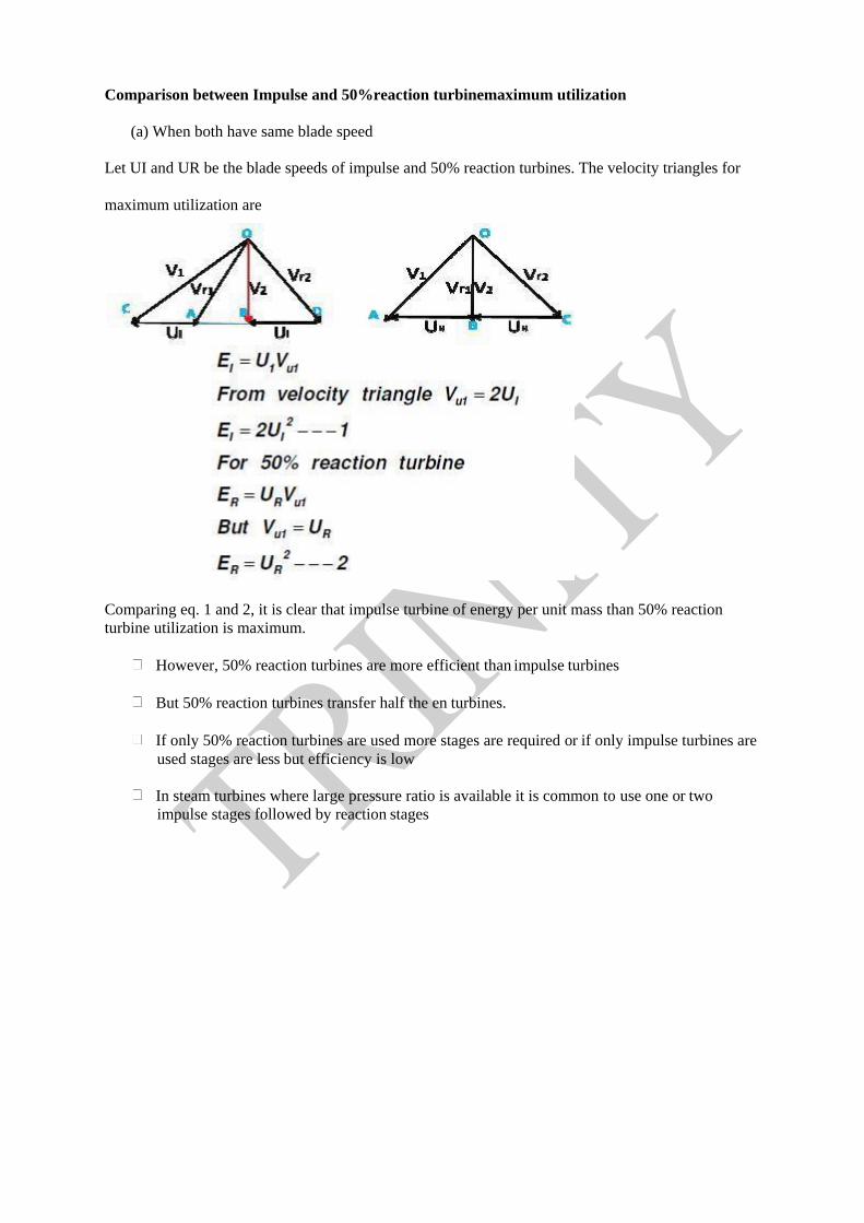
Comparison between Impulse and 50%reaction turbinemaximum utilization
(a) When both have same blade speed
Let UI and UR be the blade speeds of impulse and 50% reaction turbines. The velocity triangles for
maximum utilization are
Comparing eq. 1 and 2, it is clear that impulse turbine of energy per unit mass than 50% reaction
turbine utilization is maximum.
However, 50% reaction turbines are more efficient than impulse turbines
But 50% reaction turbines transfer half the en turbines.
If only 50% reaction turbines are used more stages are required or if only impulse turbines are
used stages are less but efficiency is low
In steam turbines where large pressure ratio is available it is common to use one or two
impulse stages followed by reaction stages
Module: 3
STEAM TURBINES
Introduction:
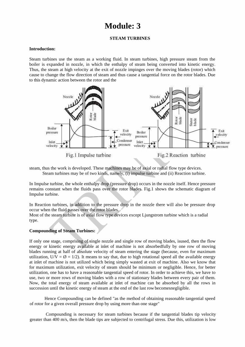
Steam turbines use the steam as a working fluid. In steam turbines, high pressure steam from the
boiler is expanded in nozzle, in which the enthalpy of steam being converted into kinetic energy.
Thus, the steam at high velocity at the exit of nozzle impinges over the moving blades (rotor) which
cause to change the flow direction of steam and thus cause a tangential force on the rotor blades. Due
to this dynamic action between the rotor and the
steam, thus the work is developed. These machines may be of axial or radial flow type devices.
Steam turbines may be of two kinds, namely, (i) impulse turbine and (ii) Reaction turbine.
In Impulse turbine, the whole enthalpy drop (pressure drop) occurs in the nozzle itself. Hence pressure
remains constant when the fluids pass over the rotor blades. Fig.1 shows the schematic diagram of
Impulse turbine.
In Reaction turbines, in addition to the pressure drop in the nozzle there will also be pressure drop
occur when the fluid passes over the rotor blades.
Most of the steam turbine is of axial flow type devices except Ljungstrom turbine which is a radial
type.
Compounding of Steam Turbines:
If only one stage, comprising of single nozzle and single row of moving blades, isused, then the flow
energy or kinetic energy available at inlet of machine is not absorbedfully by one row of moving
blades running at half of absolute velocity of steam entering the stage (because, even for maximum
utilization, U/V = Ø = 1/2). It means to say that, due to high rotational speed all the available energy
at inlet of machine is not utilized which being simply wasted at exit of machine. Also we know that
for maximum utilization, exit velocity of steam should be minimum or negligible. Hence, for better
utilization, one has to have a reasonable tangential speed of rotor. In order to achieve this, we have to
use, two or more rows of moving blades with a row of stationary blades between every pair of them.
Now, the total energy of steam available at inlet of machine can be absorbed by all the rows in
succession until the kinetic energy of steam at the end of the last row becomesnegligible.
Hence Compounding can be defined "as the method of obtaining reasonable tangential speed
of rotor for a given overall pressure drop by using more than one stage"
Compounding is necessary for steam turbines because if the tangential blades tip velocity
greater than 400 m/s, then the blade tips are subjected to centrifugal stress. Due this, utilization is low

hence the efficiency of the stage is also low. Compounding can be done by the following methods,
namely, (i) Velocity compounding, (ii) Pressure compounding or Rateau stage (iii) Pressure-Velocity
compounding and (iv) Impulse- Reaction staging.

1. Velocity Compounding (Curtis Stage) of Impulse Turbine :
This consists of set of nozzles, rows of moving blades (rotor) &a row of stationary blades
(stator). Fig.3 shows the corresponding velocity compounding Impulse Turbine.
The function of stationary blades is to direct the steam coming from the first moving row to the next
moving row without appreciable change in velocity. All the kinetic energyavailable at the nozzle exit
is successively absorbed by all the moving rows&the steam is sent from the last moving row with low
velocity to achieve high utilization. The turbine works under this type of compounding stage is called
velocity compounded turbine.E.g.Curtis stage steam turbine
2. Pressure Compounded (Rateau Stage ) Impulse Turbine :
A number of simple impulse stages arranged in series is called as pressure compounding. In this
case, the turbine is provided with rows of fixed blades which actas a nozzle at the entry of each rows
of moving blades. The total pressure drop of steam does not take place in a single nozzle but divided
among all the rows of fixed blades which act as nozzle for the next moving rows. Fig.4 shows the
corresponding pressure compounding Impulse turbine.
Pressure compounding leads to higher efficiencies because very high flow velocities are avoided
through the use of purely convergent nozzles. For maximum utilization, the absolute
velocity of steam at the outlet of the last rotor must be axially directed. It is usual in large turbines to
have pressure compounded or reaction stages after the velocity compounded stage.
3. Pressure -Velocity Compounding:
In this method, high rotor speeds are reduced without sacrificing the efficiency or the output.
Pressure drop from the chest pressure to the condenser pressure occurs at two stages. This type of
arrangement is very popular due to simple construction as compared to pressure compounding steam
turbine.
Pressure-Velocity compounding arrangement for two stages is as shown in Fig.5. First and second
stage taken separately are identical to a velocity compounding consists of a set of nozzles and rows of
moving blades fixed to the shaft and rows of fixed blades to casing. The entire expansion takes place
in the nozzles. The high velocity steam parts with only portion of the kinetic energy in the first set of
the moving blades and then passed on to fixed blades where only change in direction of jet takes place
without appreciable loss in velocity. This jet then passes on to another set of moving vanes where

further drop in kinetic energy occurs. This type of turbine is also called CurtisTurbine.

4. Impulse- Reaction Turbine:
In this type of turbine there is application of both principles namely impulse and reaction.
This type of turbine is shown in Fig.6. The fixed blades in this arrangement corresponding to the
nozzles referred in the impulse turbine. Instead of a set of nozzles, steam is admitted for whole of the
circumference. In passing through the first row of fixed blades, the steam undergoes a small drop in
pressure and its velocity increases. Steam then enters the first row of moving blades as the case in
impulse turbine it suffers a change in direction and therefore momentum. This gives an impulse to the
blades. The pressure drop during this gives rise to reaction in the direction opposite to that of added
velocity. Thus the driving force is vector summation of impulse and reaction.
Normally this turbine is known as Reaction turbine. The steam velocity in this typeof turbine is
comparatively low, the maximum being about equal to blade velocity. This type of turbine is very
successful in practice. It is also called as Parson's Reaction turbine.
Condition for Maximum Utilization Factor or Blade efficiency with Equiangular Blades for
Impulse Turbine:
Condition for maximum utilization factor or blade efficiency with equiangular blades for Impulse
turbine and the influence of blade efficiency on the steam speed in a single stage Impulse turbine can
be obtained by considering corresponding velocity diagrams as shown in Fig.9. Due to the effect of
blade friction loss, the relative velocity at outlet is reduced than the
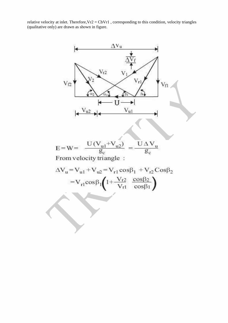
relative velocity at inlet. Therefore,Vr2 = CbVr1 , corresponding to this condition, velocity triangles
(qualitative only) are drawn as shown in figure.


Analysis on Two Stages:
Condition of Maximum Efficiency for Velocity Compounded Impulse Turbine (Curtis
Turbine)
The velocity triangles for first stage and second stage of a Curtis turbine are as shown In
above figure. The speed and the angles should be so selected that the final absolute velocity of steam
leaving the second row is axial, so as to obtain maximum efficiency. The tangential speed of blade
for both the rows is same since all the moving blades are mounted on the same shaft.
In the first row of moving blades, the work done per kg of steam is, W1
=U (Vu1 +Vu2)/gc =UVu1/gc
From I stage velocity triangle, we get, W1 =U (Vr1cosβ +Vr2cos)/g If β1= β2 and Vr1 = Vr2, then,
W1 =2U (Vr1cos β1) /g
W1=2U (V1cosα1 - U) /g
The magnitude of the absolute velocity of steam leaving the first row is same as the velocity of steam
entering the second row of moving blades, if there is no frictional loss (i.e.,V2 =V3 ) but only the
direction is going to be changed.
In the second moving row, work done per kg of steam is,
W2 =U Vu2 /g = U (Vr3cos β3 + Vr4cos ) /g
Again if β3= β4 and Vr3 = Vr4
W2 =2U (Vr3cos β3) /g
W2=2U (V3 cosα3 - U) /g

If no loss in absolute velocity of steam entering from I rotor to the II rotor, then V3= V2 & α3 = α2

W2=2U (V2 cosα2 - U) /g
Also, V2 cosα2 = Vr2cos β2-U= Vr1cosβ1 - U. (Vr1 = Vr2 & β1 = β2)
V2 cosα2 = (V1 cosα2 - U) –U (Vr1cos β1 = V1 cosα1 - U)
V2 cosα2 = V1 cosα1 -2U
W2 = 2U (V1cos α1 - 3U) /g
Total Work done per kg of steam from both the stages is given by
WT =W1 +W2 =2U [V1 cosα1 - 3U+ V1 cosα1 - U]/g
WT =2U [2V1 cosα1- 4U]/g
WT =4U [V1 cosα1- 2U]/g
In general form, the above equation can be expressed as,
W = 2 n U [V1 cosα1 - nU]/g
Where, n = number of stages.
Then the blade efficiency is given by,
And work done in the last row =1/2n of total work
V1 =Absolute velocity of steam entering the first rotor or steam velocity at the exit of the
nozzle, m/s.
α1= Nozzle angle with respect to wheel plane or tangential blade speed at inlet to the first rotor,
degrees.
Vr1 = Relative velocity of fluid at inlet of I stage, m/s.
β1= Rotor or blade angle at inlet of 1 rotor made byV, degree Vr2
= Relative velocity of fluid at outlet of I stage.
β2= Rotor or blade angle at outlet of I rotor made degree
V2 =Absolute velocity of steam leaving the I rotor or stage, m/s α2=
Exit angle of steam made by V2, degree
V3 = Absolute velocity of steam entering the 2 rotor or exit velocity of the steam from the stator
m/s.
α3= Exit angle of stator for 2 rotor, degree
Module: 4
HYDRAULIC TURBINES
Introduction:
Hydraulic (water) turbines are the machines which convert the water energy (Hydro power)
into Mechanical energy. The water energy may be either in the form of potential energy as we find in
dams, reservoirs, or in the form of kinetic energy in flowing water. The shaft of the turbine directly
coupled to the electric generator which converts mechanical energy in to electrical energy. This is
known as “Hydro-Electric power".
Classification of Hydraulic Turbines:
Water turbines are classified into various kinds according to i) the action of water on blades,
ii) based on the direction of fluid flow through the runner and iii) the specific speed of the machine.
(i)Based on a Francis turbine Action of Water on Blades:
These may be classified into:1) Impulse type and 2) Reaction type
In impulse turbine, the pressure of the flowing fluid over the runner is constant andgenerally equal
to an atmospheric pressure. All the available potential energy at inlet willbe completely converted into
which in turn utilized through apurely impulse effect to produce work. Therefore, in impulse turbine,
the available energyat the inlet of a turbine is only the kinetic energy.
In reaction turbine, the turbine casing is filled with water and the water pressurechanges during
flow through the rotor in addition to kinetic energy from nozzle (fixedblades).As a whole, both the
pressure and are available at the inlet ofreaction turbines for producing power.
(ii) Based on the direction of Flow of Fluid through Runner:
Hydraulic machines are classified into:
a) Tangential or peripheral flow
b) Radial inward or outward flow
c) Mixed or diagonal flow
d) Axial flow types.
a) Tangential Flow Machines:
In tangential flow turbines, the water flows along the tangent to the path of rotationof the
runner. Example:Pelton wheel
b) Radial Flow Machines:
In radial flow machine, the water flows along the radial direction and flow remains
normal to the axis of rotation as it passes through the runner. It may be inward flow or outward
flow.
In Inward flow turbines, the water enters at the outer periphery and passes through the runner
inwardly towards the axis of rotation and finally leaves at inner periphery.
Example: Francis turbine. In outward flow machines the flow direction is opposite to the inward
flow machines.

c) Mixed or Diagonal Flow:

In this type of turbine, the flow of fluid may enter at the outer periphery, passes over the
runner inwardly and leaves axially or parallel to the axis of rotation and vice-versa Examples:
Modern Francis turbine, Deriaz turbine d) Axial Flow Devices:
In this type of turbine, the water along the direction parallel to the axis of rotation.
Examples: Kaplan turbine, propeller turbine etc.
(iii) Based on Specific Speed:
Hydraulic turbines are classified into:
(a) Low Specific Speed: Which employs high head in the range of 200m up to 1700 m
This machine requires low discharge. Examples: Pelton wheel. NS = 10 to 30 single jet and
30 to 50 for double jet Pelton wheel.
(b) Medium Specific Speed: Which employs moderate heads in the range of 50m to 200
m. Example: Francis turbine, NS = 60 to 400.
(c) High Specific Speed: Which employs very low heads in the range of 2.5mto 50 m
These require high discharge. Examples: Kaplan, Propeller etc., N = 300 to 1000
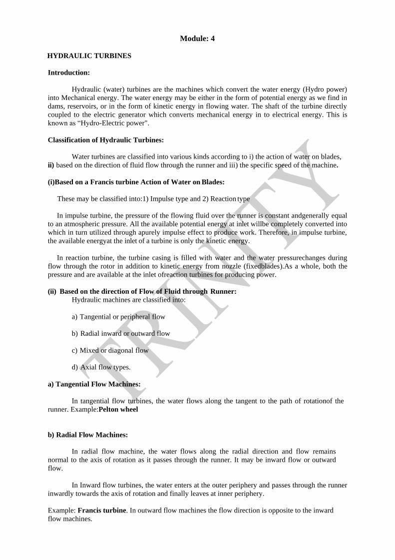
PeltonWheel:
This is a impulse type of tangential flow hydraulic turbine. It mainly posses: (i) Nozzle (ii) runner and
buckets (iii) casing (iv) Brake nozzle. Fig. 1 shows general layout of hydro-electric power plant with
pelton wheel.
The water from the dam is made to flow through the penstock. At the end of the penstock, nozzle is
fitted which convert the potential energy into high kinetic energy. The speed of the jet issuing from
the nozzle can be regulated by operating the spear head by varying the flow area. The high velocity of
jet impinging over the buckets due to which the runner starts rotating because of the impulse effects
and thereby hydraulic energy is converted into mechanical energy. After the runner, the water falls
into tail race. Casing will provide the housing for runner and is open to atmosphere. Brake nozzles are
used to bring the runner from high speed to rest condition whenever it is to be stopped. In order to
achieve this water is made to flow in opposite direction to that of runner.
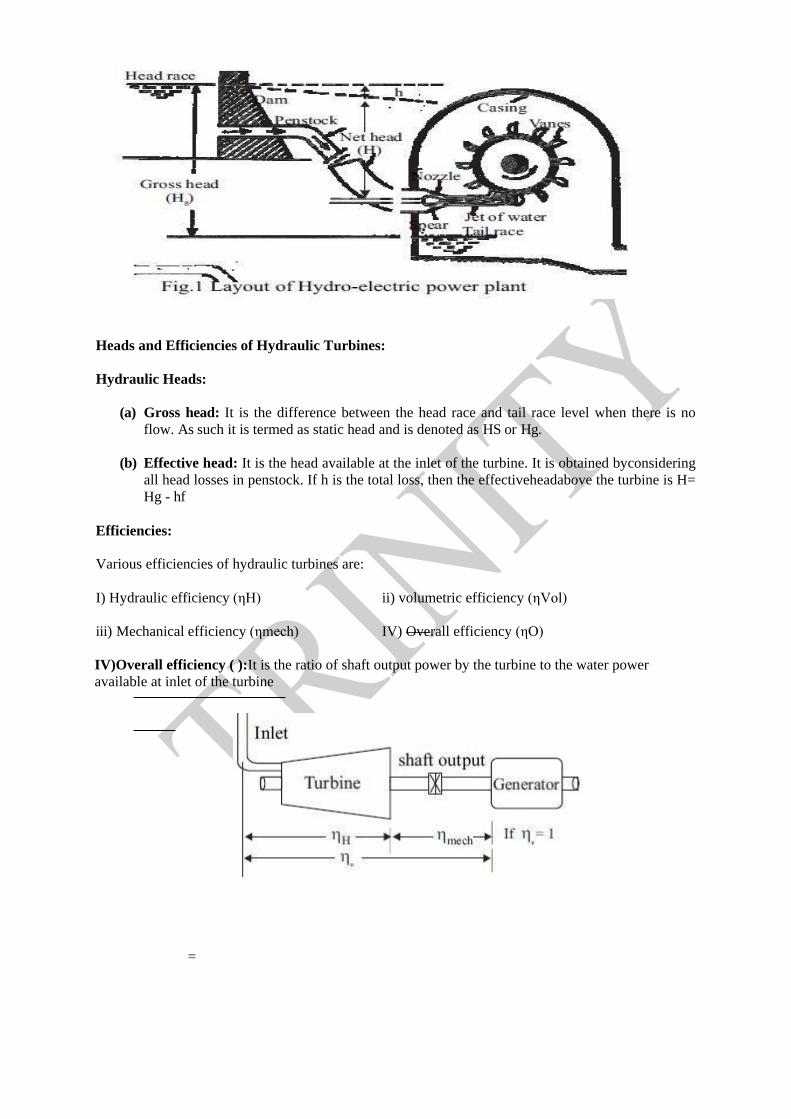
Heads and Efficiencies of Hydraulic Turbines:
Hydraulic Heads:
(a) Gross head: It is the difference between the head race and tail race level when there is no
flow. As such it is termed as static head and is denoted as HS or Hg.
(b) Effective head: It is the head available at the inlet of the turbine. It is obtained byconsidering
all head losses in penstock. If h is the total loss, then the effectiveheadabove the turbine is H=
Hg - hf
Efficiencies:
Various efficiencies of hydraulic turbines are:
I) Hydraulic efficiency (ηH) ii) volumetric efficiency (ηVol)
iii) Mechanical efficiency (ηmech) IV) Overall efficiency (ηO)
IV)Overall efficiency ( ):It is the ratio of shaft output power by the turbine to the water power
available at inlet of the turbine
=
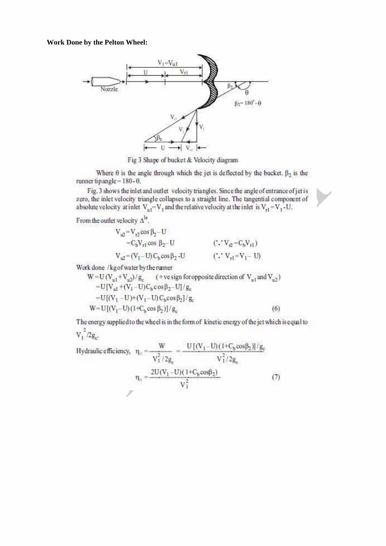
Work Done by the Pelton Wheel:


Reaction Turbine:
In reaction turbines, only part of total head of water at inlet is converted intovelocity head before it
enters the runner and the remaining part of total head is converted in the runner as the water flows
over it. In these machines, the water is completely filled in all the passages of runner. Thus, the
pressure of water gradually changes as it passes through the runner. Hence, for this kind of machines
both pressure energy and kinetic energy are available at inlet. E.g. Francis turbine, Kaplan turbines,
Deriaz turbine.
Francis turbine which is of mixed flow type is as shown in Fig. 4. It is of inward flow type of
turbine in which the water enters the runner radially at the outer periphery and leaves axially at its
center.
This turbine consists of: (i) Scrollcasing (ii) Stayring (iii) Guidevanes (iv) Runner (v) Draft
tube.
(i) Scroll Casing: The water from penstock enters the scroll casing (called spiral casing) which
completely surrounds the runner. The main function of spiral casing is to provide an uniform
distribution of water around the runner and hence to provide constant velocity. In order to provide
constant velocity, the cross sectional area of the casing gradually decreses as the water reaching
runner
(ii) Stay ring: The water from scroll casing enters the speed vane or stay ring. These are fixed blades
and usually half in number of the guide vanes. Their function is to (a)direct the water over the guide

vanes, (b) resist the load on turbine due to internal
pressure of water and these loads is transmitted to
the foundation.
(iii) Guide Vanes: Water after the stay ring passes over to the series of guide vanes or fixed vanes.
They surrounds completely around the turbine runner. Guide vanes functions are to (a) regulate the
quantity of water entering the runner and (b) direct the water on to the runner.
(iv) Runner: The main purpose of the other components is to lead the water to the runner with
minimum loss of energy. The runner of turbine is consists of series of curved blades (16 to 24) evenly
arranged around the circumference in the space between the two plate. The vanes are so shaped that
water enters the runner radially at outer periphery and leaves it axially at its center. The change in
direction of flow from radial to axial when passes over the runner causes the appreciable change in
circumferential force which in turn responsible to develop power.
(v) Draft Tube: The water from the runner flows to the tail race through the draft tube. Adraft is a
pipe or passage of gradually increasing area which connect the exit of the runner to the tail race. It
may be made of cast or plate steel or concrete. The exit end of the draft tube is always submerged
below the level of water in the tail race and must be air-tight.
The draft tube has two purposes:
(a) It permits a negative or suction head established at the runner exit, thus making it possible to
install the turbine above the tail race level without loss of head.
(b) It converts large proportion of velocity energy rejected from the runner into useful pressure
energy
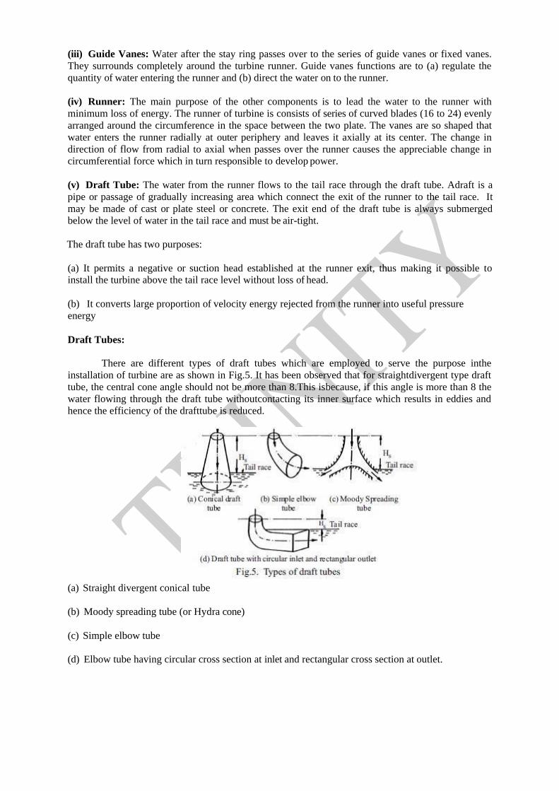
Draft Tubes:
There are different types of draft tubes which are employed to serve the purpose inthe
installation of turbine are as shown in Fig.5. It has been observed that for straightdivergent type draft
tube, the central cone angle should not be more than 8.This isbecause, if this angle is more than 8 the
water flowing through the draft tube withoutcontacting its inner surface which results in eddies and
hence the efficiency of the drafttube is reduced.
(a) Straight divergent conical tube
(b) Moody spreading tube (or Hydra cone)
(c) Simple elbow tube
(d) Elbow tube having circular cross section at inlet and rectangular cross section at outlet.
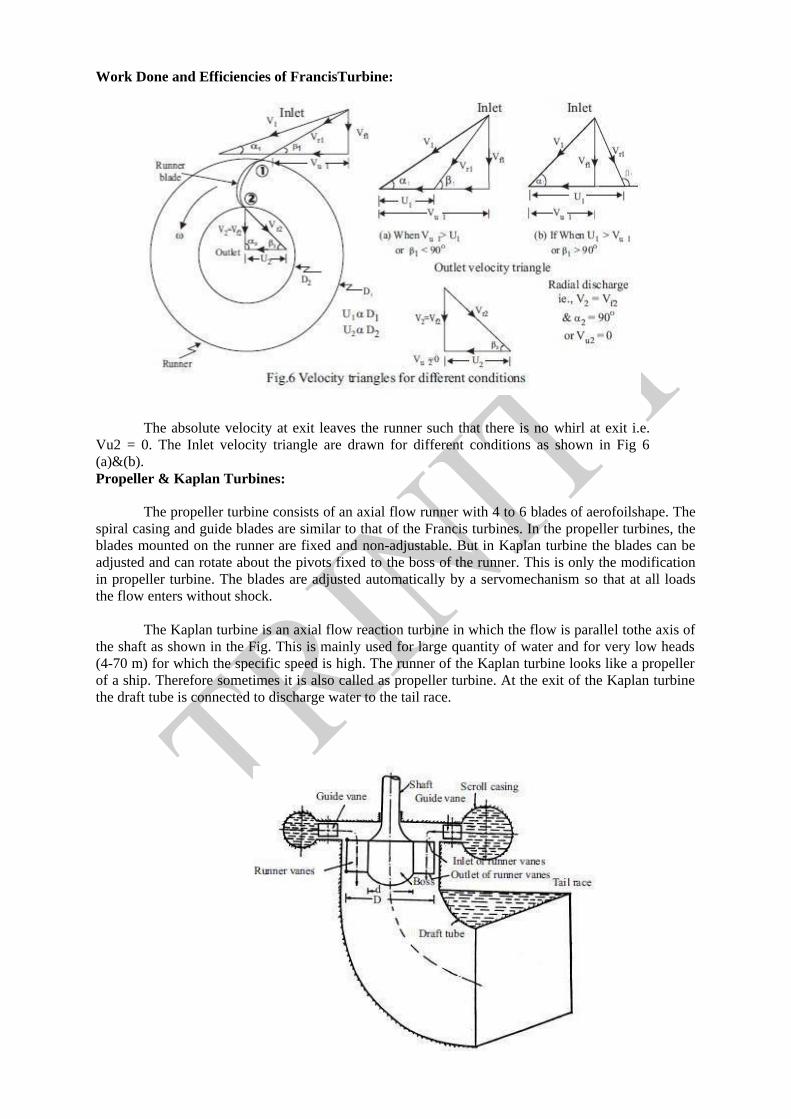
Work Done and Efficiencies of FrancisTurbine:
The absolute velocity at exit leaves the runner such that there is no whirl at exit i.e.
Vu2 = 0. The Inlet velocity triangle are drawn for different conditions as shown in Fig 6
(a)&(b).
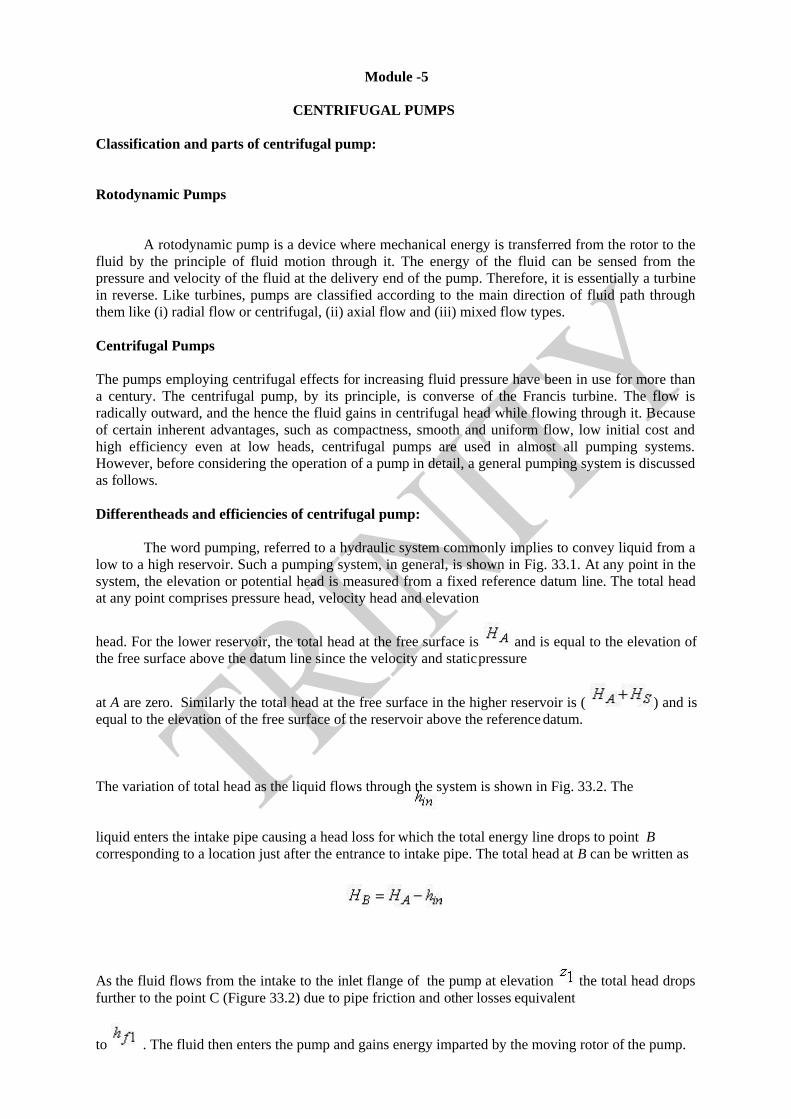
Propeller & Kaplan Turbines:
The propeller turbine consists of an axial flow runner with 4 to 6 blades of aerofoilshape. The
spiral casing and guide blades are similar to that of the Francis turbines. In the propeller turbines, the
blades mounted on the runner are fixed and non-adjustable. But in Kaplan turbine the blades can be
adjusted and can rotate about the pivots fixed to the boss of the runner. This is only the modification
in propeller turbine. The blades are adjusted automatically by a servomechanism so that at all loads
the flow enters without shock.
The Kaplan turbine is an axial flow reaction turbine in which the flow is parallel tothe axis of
the shaft as shown in the Fig. This is mainly used for large quantity of water and for very low heads
(4-70 m) for which the specific speed is high. The runner of the Kaplan turbine looks like a propeller
of a ship. Therefore sometimes it is also called as propeller turbine. At the exit of the Kaplan turbine
the draft tube is connected to discharge water to the tail race.

1) At inlet, the velocity le is as shown in below Fig
2) At the outlet, the discharge is always axial with no whirl velocity component i.e., outlet
velocity triangle just a right angle triangle as shown below Fig.
Module -5
CENTRIFUGAL PUMPS
Classification and parts of centrifugal pump:
Rotodynamic Pumps
A rotodynamic pump is a device where mechanical energy is transferred from the rotor to the
fluid by the principle of fluid motion through it. The energy of the fluid can be sensed from the
pressure and velocity of the fluid at the delivery end of the pump. Therefore, it is essentially a turbine
in reverse. Like turbines, pumps are classified according to the main direction of fluid path through
them like (i) radial flow or centrifugal, (ii) axial flow and (iii) mixed flow types.
Centrifugal Pumps
The pumps employing centrifugal effects for increasing fluid pressure have been in use for more than
a century. The centrifugal pump, by its principle, is converse of the Francis turbine. The flow is
radically outward, and the hence the fluid gains in centrifugal head while flowing through it. Because
of certain inherent advantages, such as compactness, smooth and uniform flow, low initial cost and
high efficiency even at low heads, centrifugal pumps are used in almost all pumping systems.
However, before considering the operation of a pump in detail, a general pumping system is discussed
as follows.
Differentheads and efficiencies of centrifugal pump:
The word pumping, referred to a hydraulic system commonly implies to convey liquid from a
low to a high reservoir. Such a pumping system, in general, is shown in Fig. 33.1. At any point in the
system, the elevation or potential head is measured from a fixed reference datum line. The total head
at any point comprises pressure head, velocity head and elevation
head. For the lower reservoir, the total head at the free surface is and is equal to the elevation of
the free surface above the datum line since the velocity and static pressure
at A are zero. Similarly the total head at the free surface in the higher reservoir is ( ) and is
equal to the elevation of the free surface of the reservoir above the reference datum.
The variation of total head as the liquid flows through the system is shown in Fig. 33.2. The
liquid enters the intake pipe causing a head loss for which the total energy line drops to point B
corresponding to a location just after the entrance to intake pipe. The total head at B can be written as
As the fluid flows from the intake to the inlet flange of the pump at elevation the total head drops
further to the point C (Figure 33.2) due to pipe friction and other losses equivalent
to . The fluid then enters the pump and gains energy imparted by the moving rotor of the pump.

This raises the total head of the fluid to a point D (Figure 33.2) at the pump outlet (Figure 33.1).
In course of flow from the pump outlet to the upper reservoir, friction and other losses
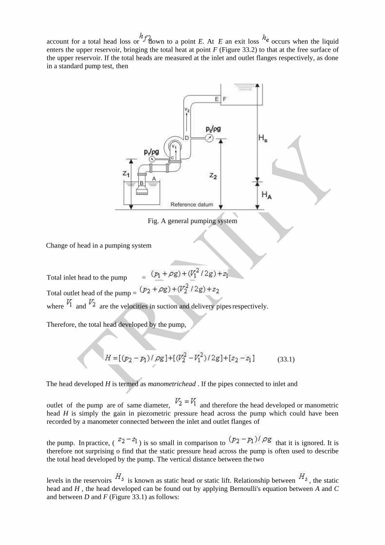
account for a total head loss or down to a point E. At E an exit loss occurs when the liquid
enters the upper reservoir, bringing the total heat at point F (Figure 33.2) to that at the free surface of
the upper reservoir. If the total heads are measured at the inlet and outlet flanges respectively, as done
in a standard pump test, then
Fig. A general pumping system
Change of head in a pumping system
Total inlet head to the pump
Total outlet head of the pump =
where and are the velocities in suction and delivery pipes respectively.
Therefore, the total head developed by the pump,
(33.1)
The head developed H is termed as manometrichead . If the pipes connected to inlet and
outlet of the pump are of same diameter, and therefore the head developed or manometric
head H is simply the gain in piezometric pressure head across the pump which could have been
recorded by a manometer connected between the inlet and outlet flanges of
the pump. In practice, ( ) is so small in comparison to that it is ignored. It is
therefore not surprising o find that the static pressure head across the pump is often used to describe
the total head developed by the pump. The vertical distance between the two
levels in the reservoirs is known as static head or static lift. Relationship between , the static
head and H , the head developed can be found out by applying Bernoulli's equation between A and C
and between D and F (Figure 33.1) as follows:
=

Between D and F ,
substituting from Eq. (33.2) into Eq. (33.3), and then with the help of Eq. (33.1),
we can write
Therefore, we have, the total head developed by the pump = static head + sum of all the losses.
The simplest form of a centrifugal pump is shown in Figure. It consists of three important parts: (i)
the rotor, usually called as impeller, (ii) the volute casing and (iii) the diffuser ring. The impeller is a
rotating solid disc with curved blades standing out vertically from the face of the disc. The impeller
may be single sided double sided A double sided impeller has a relatively small flow capacity.
centrifugal pump
The tips of the blades are sometimes covered by another flat disc to give shrouded blades otherwise
the blade tips are left open and the casing of the pump itself forms the solid outer
wall of the blade passages. The advantage of the shrouded blade is that flow is prevented from leaking
across the blade tips from one passage to another
(a) Single sided impeller (b) Double sided impeller (c) Shrouded impeller Figure 33.4
Types of impellers in a centrifugal pump
As the impeller rotates, the fluid is drawn into the blade passage at the impeller eye, the centre of the
impeller. The inlet pipe is axial and therefore fluid enters the impeller with very little whirl or
tangential component of velocity and flows outwards in the direction of the blades. The fluid receives
energy from the impeller while flowing through it and is discharged with increased pressure and
velocity into the casing. To convert the kinetic energy or fluid at the impeller outlet gradually into
pressure energy, diffuser blades mounted on a diffuser ring are used.
The stationary blade passages so formed have an increasing cross-sectional area which reduces the
flow velocity and hence increases the static pressure of the fluid. Finally, the fluid moves from the
diffuser blades into the volute casing which is a passage of gradually increasing cross-section and also
serves to reduce the velocity of fluid and to convert some of the velocity head into static head.
Sometimes pumps have only volute casing without any diffuser.
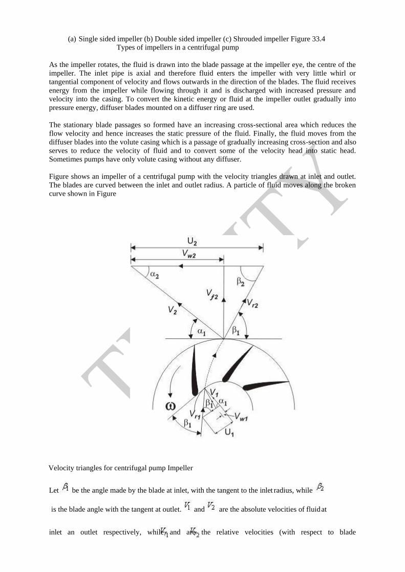
Figure shows an impeller of a centrifugal pump with the velocity triangles drawn at inlet and outlet.
The blades are curved between the inlet and outlet radius. A particle of fluid moves along the broken
curve shown in Figure
Velocity triangles for centrifugal pump Impeller
Let be the angle made by the blade at inlet, with the tangent to the inlet radius, while
is the blade angle with the tangent at outlet. and are the absolute velocities of fluid at
inlet an outlet respectively, while and are the relative velocities (with respect to blade

velocity) at inlet and outlet respectively. Therefore,
Work done on the fluid per unit weight =
A centrifugal pump rarely has any sort of guide vanes at inlet. The fluid therefore approaches the
impeller without appreciable whirl and so the inlet angle of the blades is designed to produce a right-
angled velocity triangle at inlet (as shown in Fig. 34.1). At conditions other
than those for which the impeller was designed, the direction of relative velocity does not coincide
with that of a blade. Consequently, the fluid changes direction abruptly on entering the impeller. In
addition, the eddies give rise to some back flow into the inlet pipe, thus causing fluid to have some
whirl before entering the impeller. However, considering the
operation under design conditions, the inlet whirl velocity and accordingly the inlet
angular momentum of the fluid entering the impeller is set to zero. Therefore, Eq. (34.1) can be
written as
Work done on the fluid per unit weight =
We see from this equation that the work done is independent of the inlet radius. The difference in total
head across the pump known as manometric head, is always less than the
quantity because of the energy dissipated in eddies due to friction.
The ratio of manometric head H and the work head imparted by the rotor on the
fluid (usually known as Euler head) is termed as manometricefficiency . It represents the
effectiveness of the pump in increasing the total energy of the fluid from the energy given to it by the
impeller. Therefore, we can write
The overall efficiency of a pump is defined as
where, Q is the volume flow rate of the fluid through the pump, and P is the shaft power, i.e.
the input power to the shaft. The energy required at the shaft exceeds because of friction
in the bearings and other mechanical parts. Thus a mechanical efficiency is defined as
So that

Cavitation

Need for priming
The action taken to stimulate an economy, usually during a recessionary period, through
government spending, and interest rate and tax reductions. The term "pump priming" is derived from
the operation of older pumps; a suction valve had to be primed with water so that the pump would
function properly. As with these pumps, pump priming assumes that the economy must be primed to
function properly once again. In this regard, government spending is assumed to stimulate private
spending, which in turn should lead to economic expansion.
Slip Factor
Under certain circumstances, the angle at which the fluid leaves the impeller may not be the same as
the actual blade angle. This is due to a phenomenon known as fluid slip, which
finally results in a reduction in the tangential component of fluid velocity at impeller outlet. One
possible explanation for slip is given as follows.
In course of flow through the impeller passage, there occurs a difference in pressure and velocity
between the leading and trailing faces of the impeller blades. On the leading face of a blade there is
relatively a high pressure and low velocity, while on the trailing face, the pressure is lower and hence
the velocity is higher. This results in a circulation around the blade and a non-uniform velocity
distribution at any radius. The mean direction of flow at
outlet, under this situation, changes from the blade angle at outlet to a different angle
as shown in Figure 34.2 Therefore the tangential velocity component at outlet is
reduced to , as shown by the velocity triangles in Figure 34.2, and the difference is
defined as the slip. The slip factor is defined as
CENTRIFUGAL COMPRESSORS
Introduction
Power absorbing Turbo machines used to handle compressible fluids like air, gases etc, can
be broadly classified into: (i) Fans (ii) Blowers and (iii) Compressors. These machinesproduce the
head (pressure) in the expense of mechanical energy input. The pressure rise incentrifugal type
machines are purely due to the centrifugal effects.
A fan usually consists of a single rotor with or without a stator. It causes only a smallpressure
rise as low as a few centimeters of water column. Generally it raises the pressure up to amaximum of
0.07 bar (70 cm WG). In the analysis of the fan, the fluid will be treated asincompressible as the
density change is very small due to small pressure rise. Fans are used forair circulation in buildings,
for ventilation, in automobiles in front of engine for cooling purposesetc.
Blower may consist of one or more stages of compression with its rotors mounted on
acommon shaft. The air is compressed in a series of successive stages and is passed through adiffuser
located near the exit to recover the pressure energy from the large kinetic energy. Theoverall pressure
rise may be in the range of 1.5 to 2.5 bars. Blowers are used in ventilation,power station, workshops
etc.
Compressor is used to produce large pressure rise ranging from 2.5 to 10 bar or more. Asingle
stage compressor can generally produce a pressure rise up to 4 bars. Since the velocities ofair flow are
quite high, the Mach number and compressibility effects may have to be taken intoaccount in
evaluating the stage performance of a compressor.
In general the centrifugal compressor may be known as a fan, blower, supercharger
etc,depending on the need to be served. Broadly speaking, fans are the low-pressure
compressors;blowers are the medium pressure compressors. It is therefore the analysis of one, say
centrifugalcompressor, will also holds good to the other machines like blower, fans.
Important Elements of a Centrifugal Compressor
Fig. shows the essential parts of a typical centrifugal compressor. It mainly consists of
(i) Inlet casing with the converging nozzle (ii) the impeller (iii) the diffuser and (iv) The outletcasing.
The function of the inlet casing with the conversant nozzle is to accelerate the enteringfluid to
the impeller inlet. The inlet nozzle accelerates the fluid from the initial condition (state 0)to the entry
of the Inlet Guide Vanes (IGV) which direct the flow in the desired direction at theinlet of the
impeller (state 1).
The impeller convert the supplied mechanical energy into fluid energy whereby the fluidkinetic
energy and the static pressure rises. An impeller is made of radial blades which arebrazed to the
shroud. It can be made from a single piece consisting of both the inducer and a
Largely radial portion. The inducer receives the flow between the hub and tip diameters (dh anddt ) of
the impeller eye and passes on to the radial portion of the impeller blades. The flowapproaching the
impeller may be with or without swirl. The inlet diameter 4.2 Important
Elements of a Centrifugal CompressorFig. show the essential parts of a typical centrifugal
compressor. It mainly consists of(i) inlet casing with the converging nozzle (ii) the impeller (iii) the
diffuser and (iv) the outletcasing.
The function of the inlet casing with the conversant nozzle is to accelerate the enteringfluid to
the impeller inlet. The inlet nozzle accelerates the fluid from the initial condition (state 0)to the entry
of the Inlet Guide Vanes (IGV) which direct the flow in the desired direction at theinlet of the
impeller (state 1).
The impeller convert the supplied mechanical energy into fluid energy whereby the
fluidkinetic energy and the static pressure rises. An impelbrazed to the shroud. It can be made from a
single piece consisting of both the inducer and alargely radial portion. The inducer receives the flow
between the hub and tip diameters (dhanddt) of the impeller eye and passes on to the radial portion of
the impeller blades. The flowapproaching the impeller may be with or without swirl.
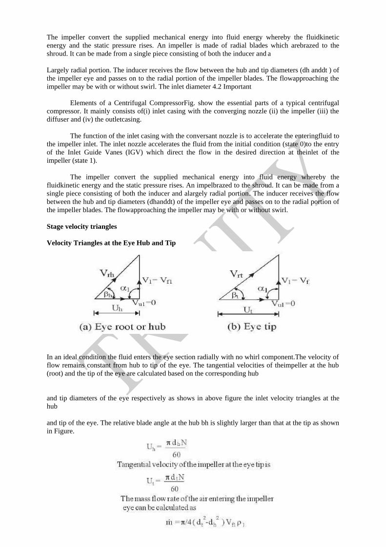
Stage velocity triangles
Velocity Triangles at the Eye Hub and Tip
In an ideal condition the fluid enters the eye section radially with no whirl component.The velocity of
flow remains constant from hub to tip of the eye. The tangential velocities of theimpeller at the hub
(root) and the tip of the eye are calculated based on the corresponding hub
and tip diameters of the eye respectively as shows in above figure the inlet velocity triangles at the
hub
and tip of the eye. The relative blade angle at the hub bh is slightly larger than that at the tip as shown
in Figure.
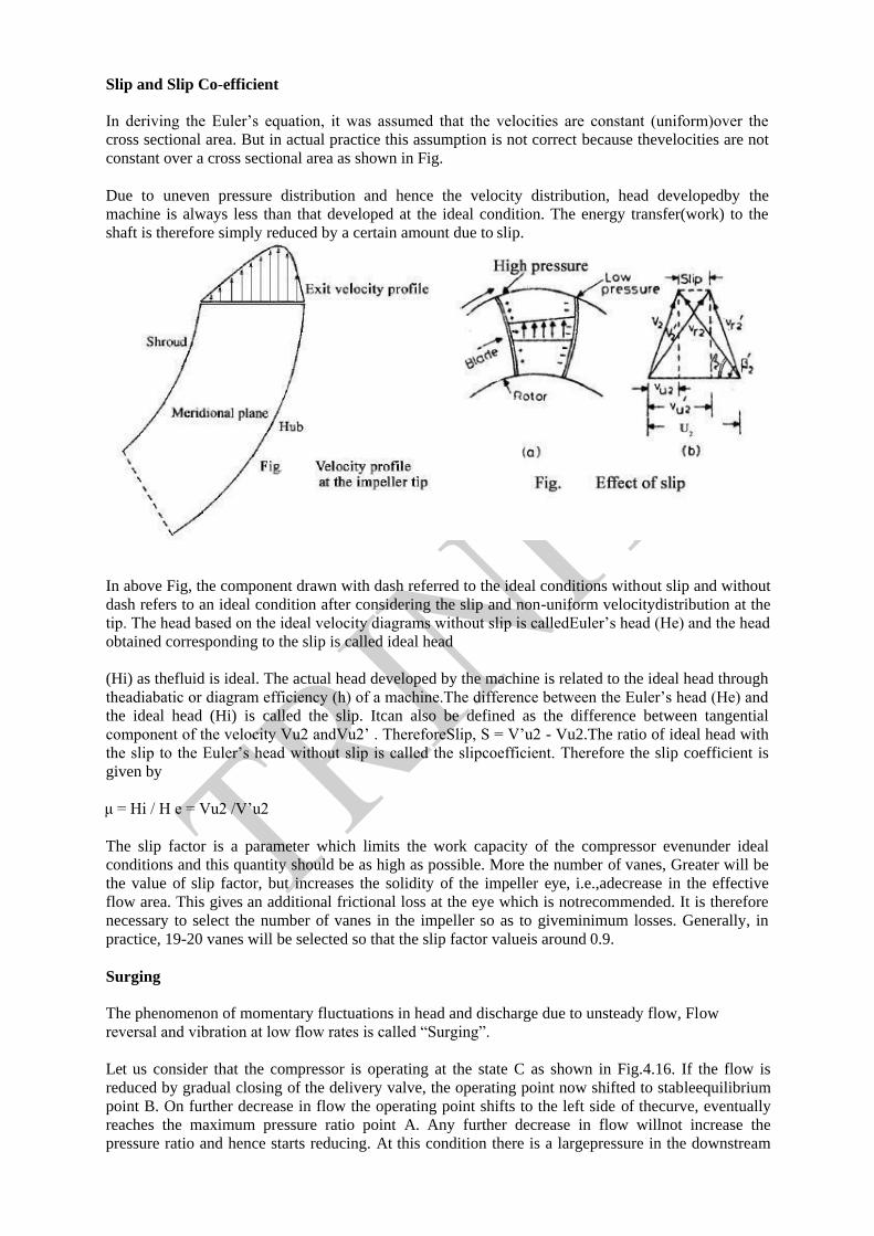
Slip and Slip Co-efficient
In deriving the Euler’s equation, it was assumed that the velocities are constant (uniform)over the
cross sectional area. But in actual practice this assumption is not correct because thevelocities are not
constant over a cross sectional area as shown in Fig.
Due to uneven pressure distribution and hence the velocity distribution, head developedby the
machine is always less than that developed at the ideal condition. The energy transfer(work) to the
shaft is therefore simply reduced by a certain amount due to slip.
In above Fig, the component drawn with dash referred to the ideal conditions without slip and without
dash refers to an ideal condition after considering the slip and non-uniform velocitydistribution at the
tip. The head based on the ideal velocity diagrams without slip is calledEuler’s head (He) and the head
obtained corresponding to the slip is called ideal head
(Hi) as thefluid is ideal. The actual head developed by the machine is related to the ideal head through
theadiabatic or diagram efficiency (h) of a machine.The difference between the Euler’s head (He) and
the ideal head (Hi) is called the slip. Itcan also be defined as the difference between tangential
component of the velocity Vu2 andVu2’ . ThereforeSlip, S = V’u2 - Vu2.The ratio of ideal head with
the slip to the Euler’s head without slip is called the slipcoefficient. Therefore the slip coefficient is
given by
μ = Hi / H e = Vu2 /V’u2
The slip factor is a parameter which limits the work capacity of the compressor evenunder ideal
conditions and this quantity should be as high as possible. More the number of vanes, Greater will be
the value of slip factor, but increases the solidity of the impeller eye, i.e.,adecrease in the effective
flow area. This gives an additional frictional loss at the eye which is notrecommended. It is therefore
necessary to select the number of vanes in the impeller so as to giveminimum losses. Generally, in
practice, 19-20 vanes will be selected so that the slip factor valueis around 0.9.
Surging
The phenomenon of momentary fluctuations in head and discharge due to unsteady flow, Flow
reversal and vibration at low flow rates is called “Surging”.
Let us consider that the compressor is operating at the state C as shown in Fig.4.16. If the flow is
reduced by gradual closing of the delivery valve, the operating point now shifted to stableequilibrium
point B. On further decrease in flow the operating point shifts to the left side of thecurve, eventually
reaches the maximum pressure ratio point A. Any further decrease in flow willnot increase the
pressure ratio and hence starts reducing. At this condition there is a largepressure in the downstream

of the system near exit than at compressor delivery and the flowstops momentarily, and may even
flow in the reverse direction. This reduces the downstreampressure. After short interval of time, the
compressor again starts to deliver the air and theoperating point quickly shifts to C again. Again the
pressure starts increasing and the operatingpoint moves from right to left. If the downstream
conditions are remain unchanged then onceagain the flow will breakdown after point A and the cycle
will be repeated with a high frequency.This phenomenon is called ‘surging’ or ‘pumping’.
If the surging is severe enough then the compressor may be ultimately subjected toimpact loads and
high frequency vibration leads to the physical damage due to the producing ofhigh pressures
repeatedly. Because of this phenomenon at the low flow rates, the compressorcannot operate on the
positive slope of the curve, i.e., to the left portion of the point A.4.17.2 Choking
At higher mass flow rates the behavior of the compressor will be different. If the massflow rates are
higher the characteristic curve will be along ABCD as shown in Fig.4.16. It can be Seen from Fig.
that for the increased mass flow rate the pressure ratio start decreasing andhence the density also. This
effect causes the increase of absolute velocity and angle of incidenceat the diffuser vane top. This
leads to the rapid steepening in the slope of the curve and finallyreaches a point D, beyond which
there will be no further increase in mass flow rate for any valueof pressure ratio. Therefore the
characteristic curve at this point becomes vertical and the point Don the curve is called Choking point.
Choking is therefore defined as the phenomenon in which the mass flow rate reaches to afixed value
irrespective of any of pressure ratios. Choking means the velocity of fluid in thepassage reaches the
velocity of sound at that point within the compressor. Choking may occuranywherewithin the
machine such as at the inlet, in the impeller or in the diffuser section.
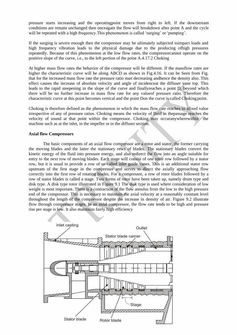
Axial flow Compressors
The basic components of an axial flow compressor are a rotor and stator, the former carrying
the moving blades and the latter the stationary rows of blades. The stationary blades convert the
kinetic energy of the fluid into pressure energy, and also redirect the flow into an angle suitable for
entry to the next row of moving blades. Each stage will consist of one rotor row followed by a stator
row, but it is usual to provide a row of so called inlet guide vanes. This is an additional stator row
upstream of the first stage in the compressor and serves to direct the axially approaching flow
correctly into the first row of rotating blades. For a compressor, a row of rotor blades followed by a
row of stator blades is called a stage. Two forms of rotor have been taken up, namely drum type and
disk type. A disk type rotor illustrated in Figure 9.1 The disk type is used where consideration of low
weight is most important. There is a contraction of the flow annulus from the low to the high pressure
end of the compressor. This is necessary to maintain the axial velocity at a reasonably constant level
throughout the length of the compressor despite the increase in density of air. Figure 9.2 illustrate
flow through compressor stages. In an axial compressor, the flow rate tends to be high and pressure
rise per stage is low. It also maintains fairly high efficiency

Disk type axial flow compressor
The basic principle of acceleration of the working fluid, followed by diffusion to convert
acquired kinetic energy into a pressure rise, is applied in the axial compressor. The flow is considered
as occurring in a tangential plane at the mean blade height where the blade peripheral velocity is U .
This two dimensional approach means that in general the flow velocity will have two components,
one axial and one peripheral denoted by subscript w , implying a whirl velocity. It is first assumed that
the air approaches the rotor blades with an
absolute velocity, , at an angle to the axial direction. In combination with the peripheral
velocity U of the blades, its relative velocity will be at and angle as shown in the upper
velocity triangle (Figure 9.3). After passing through the diverging passages formed between the rotor
blades which do work on the air and increase its absolute velocity, the air
will emerge with the relative velocity of at angle which is less than . This turning of air
towards the axial direction is, as previously mentioned, necessary to provide an increase in the
effective flow area and is brought about by the camber of the blades.
Since is less than due to diffusion, some pressure rise has been accomplished in the
from the rotor at an angle to the axial direction. The air then passes through the passages
formed by the stator blades where it is further diffused to velocity at an angle which
in most designs equals to so that it is prepared for entry to next stage. Here again, the turning of
the air towards the axial direction is brought about by the camber of the blades.
Overall Pressure ratio (pro)
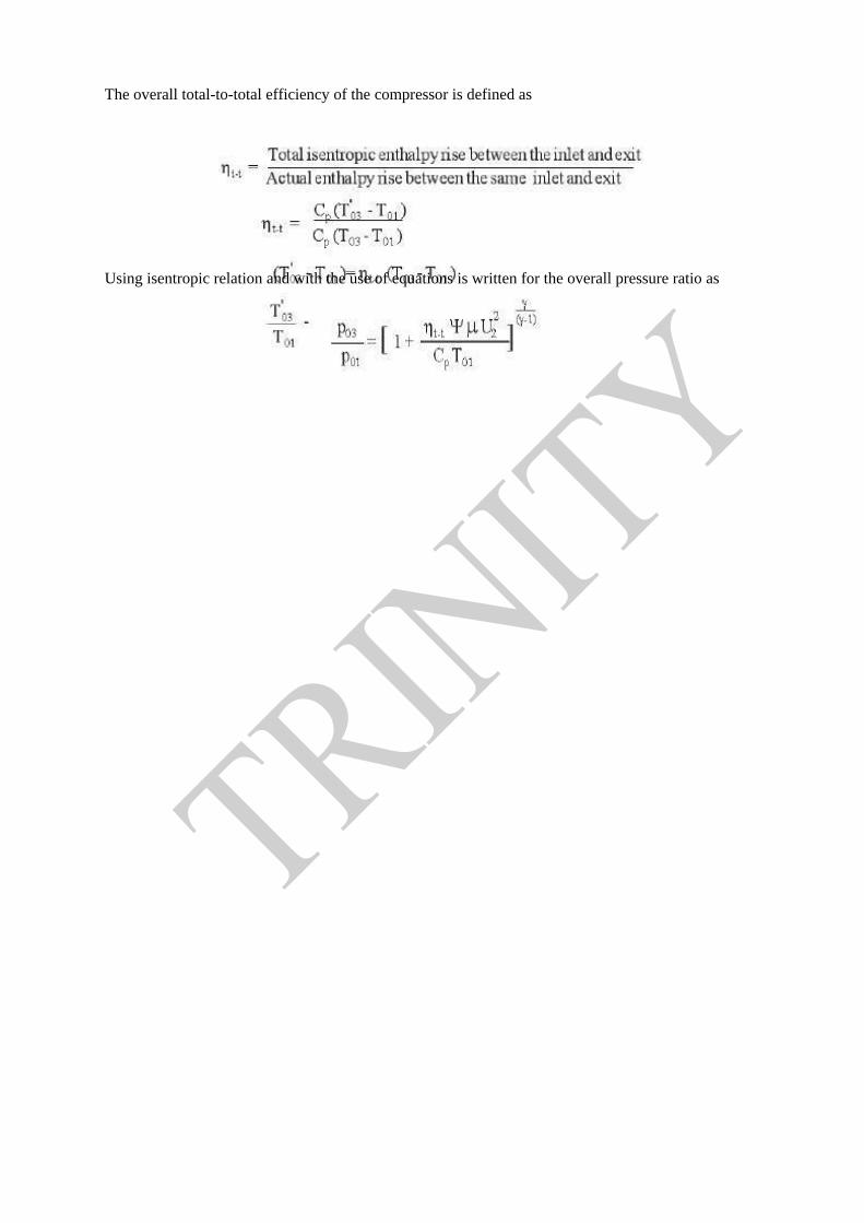
The overall total-to-total efficiency of the compressor is defined as
Using isentropic relation and with the use of equations is written for the overall pressure ratio as