tunneltalk annual review 2011 promotional issue
DESCRIPTION
The TunnelTalk Annual Review printed edition promotion issue in digital formatTRANSCRIPT

Direct by Design
An
nu
al
Re
vie
w

Direct by Design
Welcome to the digital previeW of the TunnelTalk annual revieW
This special electronic sample of the TunnelTalk Annual Review contains excerpts from articles published in the inaugural 2010 issue, as well as previews of some of the articles to be published in the forthcoming 2011 edition.
The TunnelTalk Annual Review is a top quality print publication that brings together articles first published on the TunnelTalk website into one collectable volume for your bookshelf.
It brings together the main achievements and breakthroughs, developments and discussions, challenges and resolutions of the year. From planned projects and progress of those underway to events and achievements that made each year a standout. From breakthroughs and innovations to Discussion Forum topics, awards and social events, conference reports and tributes. Each issue is the tunnelling year under one cover.
To order your own, personal copy of the Annual Review issues, please see the back page of this preview for further details.
Enjoy browsing the preview and we look forward to sending hard copies direct to your post box.

In March 2011, the world’s longest rail tunnel ever undertaken prepared to record its final breakthrough deep beneath the mountains of the Swiss Alps. The final
breakthrough to connect all headings of the first tunnel into one long tube through the base of the Gotthard Massive was recorded in October 2010.
Making history at GotthardTunnelTalk reporting
History was made on Friday 15 October 2010 when the first Bodio-Faido TBM broke
through into the drill+blast heading from Sedrun to finish 57km of rail tunnel through the base of the Swiss Alps from Erstfeld in the north and Bodio in the south.
Swiss politicians and dignitaries, project directors and contract managers as well as senior managers of the leading suppliers and the workers themselves all gathered for an official breakthrough on Friday afternoon when the TBM fired up at 2pm to cut the last 1.5m of rock and mark this truly monumental feat of civil engineering and endurance.
The crews of the TBMs and drill+blast headings blazed a trail. This last breakthrough occurred
www.TunnelTalk.com TunnelTalk AnnuAl Review 2010 7
Celebration of an epic achievement
nearly 2,000m below the top of the Alps and more than 8km from the nearest exit through the 800m deep shaft at Sedrun, and more than 13km from the access adit at Faido.
On a project of this magnitude - the longest, largest, most ambitious and most technically demanding tunnelling project of this age - there have been serious set backs and delays as crews have tunnelled into the unknown. Extreme geological conditions buried a TBM heading from the Amsteg adit for more than six months and had another TBM from the Faido adit at a standstill for five months from March to July 2010.
These and other challenges, some not related to the excavation work, have caused a slip of some
ME
GA
PR
OJ
EC
TS

ME
GA
PR
OJ
EC
TS
TunnelTalk AnnuAl Review 2010 www.TunnelTalk.com
During the course of realising the massive Gotthard Baseline project,
many different contractors and engineering firms, many thousands of workers, and legions of different suppliers and equipment manufacturers have been involved. This is a record of just a few.
Three main contracts were let for excavation of the main tunnels and their passages and chambers. • At Sedrun, the consortium of implenia/
Frutiget/Bilfinger Berger/Pizzarotti completed 11km of drill+blast headings at the bottom of the two 800m deep access shafts.
• At the south, TAT, the Tunnel AlpTransit Ticino JV comprising implenia/Alpine Bau/CSC impresa/Hochtief/impregilo completed two lots and operated two Herrenknecht TBMs running parallel for about 14km from the Bodio portal initially and then carrying on into the 11km long drives from the Faido access adit to breakthrough into the Sedrun drill+blast work.
• From the north, the AGN, Arbeitsgemeinschaft Gotthard-Basistunnel Nord JV of STRABAG AG of Switzerland and Austria, managed the two further Herrenknecht TBMs on the project for the initial
10.7km of tunnel from the Amsteg adit to breakthrough with the Sedrun drill+blast work and then the 7.1km parallel drives from the Ersteld portal to Amsteg.Herrenknecht AG supplied four
gripper rock TBMs of 8.8m to 9.5m diameter to the consortia for the north and south lots. The machines excavated a combined total of 85km of the 2 x 57km long twin tube complex. For development works and the central Sedrun drill+blast excavation, fleets of Atlas Copco and Sandvik jumbos were used with their support systems.
Muck haulage behind the advancing TBMs was via long continuous conveyors supplied by H+E Logistics but the supply-line workhorses of the long-distance headings teamed once again a familiar rail-bound duo of SCHÖMA locomotives and Mühlhäuser rolling stock. SCHÖMA supplied more than 125 powerful locomotives to the project. Mühlhäuser delivered more than 500 units to the different contractors including wagons, concrete remixers, flat cars, man-riders and specialised ambulance cars to assist in any emergency.
Concrete admixtures, shotcreting machines and a fire protection mortar
were contributions by BASF MEYCO to the different construction contracts.
DELVO® Crete Stabilizer 10 slowed down cement hydration to ensure an open time of four to six hours while GLENIUM® superplasticizers maintained workability after long distance transportation and exposure to the high temperatures in the interior of the mountain. The combination was used for cast final lining as well as shotcrete. MEYCO® SA 160 accelerator was added to shotcrete for fast solidification.
MEYCO® Fireshield 1350 fire protection mortar was supplied to protect the concrete linings from spalling damage in the event of an in-tunnel fire in the Bodio tunnel section while MEYCO® Potenza and Oruga shotcreting robots were delivered in numbers to the Erstfeld and Sedrun headings.
Many different sets of formwork were supplied to the project, several of the specialist pieces by Doka of Austria. For the Erstfeld lot its equipment lined the two large span Y-branch crossover caverns.
The congratulations of all in the international tunnelling industry goes to the workers, suppliers and all the managers involved who teamed together to bring the project to its successful end-of-excavation milestone. n
Concrete contributions to a mammoth undertaking
10 years from the original project timeline. The original plan, set in 1998, was to have the baseline railway operating in 2007. As it is, TBM excavation of the longest drives for the main tunnels started from the Bodio portals in 2001 with drill+blast work starting from the base of the deep access shaft at Sedrun in 2002. Work on the shorter TBM drives from the north Erstfeld portals started in 2006. The project is now scheduled to open at the end of 2017.
When the Gotthard Base Tunnel
opens in 2017, travel time between Zurich and Milano will be shortened by one hour. In addition, freight trains will be able to travel the straight, flat tunnel alignment with twice the load and at twice the speed. People and goods will cross the Alps faster, more safely and in a much more environmentally friendly way. The breakthrough of the first running tunnel of the twin tubes through the base of the Alps is a historic and record-setting achievement.
The last of the four Herrenknecht TBMs that have excavated much of the total underground works was working towards the very last breakthrough for the entire project in March 2011. n
References• Breakthrough milestone for Gotthard Base
Tunnel - TunnelTalk, September 2009• Gotthard TBM safely across the Piora
Mulda - TunnelTalk, Nov 2008• Bodio tunnel lining wurms - Switzerland -
TunnelTalk, Dec 2004
8
Among principle suppliers (clockwise from top left): Herrenkneckt gripper TBMs; Schöma locos and Mühlhäuser concrete remixer cars; Doka formwork; BASF MEYCO admixtures for shotcrete and final lining concrete

www.TunnelTalk.com TunnelTalk AnnuAl Review 2010
The numbers are in and the tunnel has it by a nose! As large as the numbers are for the scope of the
project, a cable-stayed bridge across the Fehmarnbelt for a fixed connection between Denmark and Germany comes in at DKK 38.5 billion (about US$7 billion or E5 billion) while the estimate for an immersed tube across the 20km strait is just slightly less at DKK 37.9 billion.
After agreeing the fixed link concept in September 2008, two teams in the Danish owner organisation, Femern A/S, developed conceptual designs and cost estimates for a four-lane highway and two-track railway connection across the sea on a cable-stayed bridge and in an immersed tube tunnel. Of these, the bridge had been considered the less expensive option through the process and therefore the favoured plan. Announcement of the cost estimates in November 2010 produced a surprise result with the immersed tube revealing a lower estimate than the bridge.
The result illustrates the tremendous work achieved by the tunnel team in exploring new concepts to reduce the
cost of building, operating and maintaining an undersea link. Changing attitudes and new techniques for reducing polluting substances into the atmosphere also played a role in the outcome.
One of the most significant cost savings was elimination of an intermediate man-made island designed to accommodate a ventilation shaft and equipment installation. Projections of low traffic volumes in the initial years, together with significant and rapid technical advances in reducing toxic emissions by road vehicles, have allowed the adoption of longitudinal ventilation in the long four-lane traffic tunnel. Instead of large ventilation buildings and the intermediate vent station island, fans will be installed in ceiling recesses at 400m intervals along the 20km link. This also optimizes the design of the tunnel’s cross section eliminating the need for separate transverse or semi-transverse ventilation ducts. “The change reduces the volume of concrete in the immersed tube elements by some 10%, which is a significant saving on a project of this scale,” said Steen Lykke, Project Director Tunnel for Femern A/S.
Since release of the cost comparisons in November 2010, Danish politicians have adopted the immersed tunnel as the preferred option. “The decision means that Femern A/S has reached an important milestone,” said Leo Larsen, CEO, Femern A/S. “As our conceptual design projects are based on a thorough technical foundation, we can now focus on ensuring that the authorities approve the project, including from an environmental perspective.”
Making the caseFewer risks, all told, in both the construction and operational phases than a cable-stayed bridge is how leaders of the project say they arrived at recommending the immersed tunnel.
A cable-stayed bridge across the Fehmarnbelt, with two free spans of 724m each, would be the largest spans ever constructed for either road or rail traffic. Compounded by the high shipping traffic in the area, this would pose significant risks in the construction phase in terms of cost overruns, delays and industrial accidents.
Contrary to expectation, an immersed tube across the 20km Fehmarnbelt between Denmark and Germany has come in a whisker less than a cable-stayed bridge.
Technical risks, long term environmental impacts, navigational safety and developments toward more carbon efficient transportation played a large part in reducing the
estimated cost of the undersea alternative and elevated it to the preferred solution.
Tunnel beats bridge for Fehmarnbelt Fixed Link
TunnelTalk reporting
ME
GA
PR
OJ
EC
TS
9
Immersed tube tunnel (left) comes in slightly less costly and considered less risky over all than the cable-stayed bridge alternative (right)

TunnelTalk AnnuAl Review 2010 www.TunnelTalk.com10
In September 2008, the Danish and German Ministers of Transport signed a treaty to establish a link across the
Fehmarnbelt between Lolland, Denmark and Fehmarn, Germany. The same treaty was subsequently approved by the Danish Parliament and the German Bundestag. The Fehmarnbelt Fixed Link will be the third major crossing in Denmark after realization of the Great Belt (1998) and the Øresund (2000) links. It represents the missing link in an efficient transport corridor between Scandinavia and Europe and will accommodate a four-lane motorway and a double track railway (Fig 1).
Denmark has assumed sole responsibility for the financing, implementation and future operation of the fixed road and rail link and for this purpose the state owned organization Femern A/S has been established. A feasibility study in 1996-1999 looked into a great number of possible solutions, including bridge and tunnel (immersed and bored) options, train shuttles, double and four lane motorways, single and double track rail, integrated or seperated from the motorway. On the basis of the study it was decided to construct a four-lane motorway and a double track railway. A cable-stayed bridge was favoured and the Danish and German Governments labelled this as the preferred solution. However, it was decided that an immersed tube tunnel alternative for the entire crossing had to be investigated during the planning stage. Variants which combine in-line or parallel bridge-tunnel combinations were not considered due to the great waterdepth, which would require a huge reclamation to
connect the bridge and tunnel for the in line option; and for economical reasons for the parallel arrangement. The final decision between either a bridge or a tunnel was to be taken only after it had become clear that both options were technically feasible and necessary approvals could be obtained.
In April 2009, Femern A/S selected the Rambøll-Arup-TEC JV for the design of the tunnel alternative.
The immersed tunnel solution will set new records in terms of its dimensions; it will be the longest tunnel and one of the deepest tunnels of this type ever built with a length of 20km and foundation depths reaching more than 40m under the sea surface. The size of the project will create major challenges for designers and future contractors and will allow for an innovative approach based on proven technology.
If constructed, the immersed tunnel, will also be the world’s longest combined road and rail tunnel; the world’s longest under water tunnel for road; and the deepest immersed tunnel with road and rail traffic. The size of the project is about five times the tunnel part of the Øresund Link between Denmark and Sweden and will require a huge logistical and qualitative challenge to build in the available construction time of approximately six years. The amount of material to be dredged for the trench is about 20 million m3 and the amount of concrete for the immersed tube elements is about 3 million m3. Production of the elements would require four to five construction facilities as used for the Øresund Link.
Operational safety in a tunnel of this length is a challenge and requires careful
Innovations for the M
EG
A P
RO
JE
CT
S
An immersed tunnel will also present considerable technical challenges. However, unlike a bridge, an immersed tunnel will not entail as many technical operations which push the limits of what has been done before. Essentially, the procedure will be the same as it was for construction of the Øresund Fixed Link’s immersed tunnel under the Drogden Channel between Denmark and Sweden, only many times longer and deeper. The Fehmarnbelt Tunnel will be just under 18km long and up to 30-40m deep, while the Øresund Tunnel is approximately 4km long and about 10m deep.
Both a cable-stayed bridge and an immersed tunnel would impact the marine environment but the preliminary conclusion is that a bridge would have slightly more significant permanent impact than an immersed tunnel.
In the interests of navigation safety, a tunnel poses fewer risks than a bridge. The Fehmarnbelt is a heavily trafficked stretch of water with 47,000 vessel transits per annum (2006). In the coming years, traffic is expected to increase substantially to about 90,000 vessel transits in 2030.
Financial factorsIn financial terms, there is very little difference between the two projects. The construction estimate (in 2008 price level) for an immersed tunnel is E5.1 billion and for a cable-stayed bridge, E5.2 billion.
The construction time for the tunnel is estimated at 6½ years, and for the bridge, 6 years. The cost of operation and maintenance is slightly higher for a tunnel than for a bridge. All told, the payback time for the two projects would be essentially the same at about 30 years for the coast-to-coast project. In a press release of the announcement, Danish Minister for Transport Hans Chr. Schmidt stated: “From an overall financial perspective, there is no difference between bridge and tunnel. The cost of the two solutions is, generally speaking, the same, which confirms the project’s sound financial basis.”
Over the coming year, Femern A/S will complete the Environmental Impact Statement to be considered by the authorities in Denmark and Germany in accordance with national regulations and submit an application for construction approval to German authorities during the first six months of 2012. A construction bill will then be submitted to the Danish Parliament, Folketinget, in 2013. Following approvals, construction of one of Europe’s biggest infrastructure projects is expected to commence in 2014 and open to traffic in 2020. n
References• Fehmarnbelt fixed link options -
TunnelTalk, June 2009 • Cost comparison for Fehmarnbelt link
options - TunnelTalk, Nov 2010 Fig 1. Integration of the road and rail Fehmarnbelt fixed link

13www.TunnelTalk.com TunnelTalk AnnuAl Review 2010
Like all things about the Alaskan Way viaduct replacement project in Seattle, Washington, the
procurement process and contract documents have their own unique variations. Managing excavation of a minimum 54ft or 16.5m diameter TBM tunnel directly under the heart of the city, in itself, pushes at the boundaries of existing urban bored tunneling experience.
Plans for replacing the 65-year old highway across Seattle’s foreshore started in 2001 when a heavy earthquake left the elevated structure severely damaged. At that time bored tunneling was rejected as being too technically demanding and too expensive compared with like-for-like viaduct replacement, at-grade schemes, or cut-and-cover subsurface alternatives.
Six years later the situation had changed. Mega TBM tunnels of 14m and 15m diameter, and more, had been completed around the world in Spain, China, Japan, Germany, the Netherlands
and Russia; techniques for geotechnical investigation and interpretation had improved; contractual mechanisms for sharing geotechnical risk, such as GBRs, had developed; and the technical capabilities of mitigating the risk of settlement damage to adjacent structures had advanced.
In a political coup that followed a period of project stalemate in 2006-2007, a powerful lobby of businessmen and advocates, working with experienced and passionate tunneling engineers, convinced State, City and County politicians that not only was the mega bored tunnel environmentally and socially preferable, it was also technically and financially feasible. After a seven-week period of frantic activity over the 2007-2008 end of year holiday period, the Washington State Governor, with the Mayor of Seattle and the King County Chief Executive, announced, in January
Shani Wallis, TunnelTalk
Alaskan Way mega-project procurement
In December 2010 it was confirmed that a group lead by Dragados-USA with designer HNTB and US contractor Tutor-Saliba had emerged with the best value proposal for the design-build contract to realize the mega TBM-bored highway tunnel to replace Seattle’s Alaskan Way viaduct. Since then the contract
has been signed, but the story in 2010 was the process by which award of contract was reached.
ME
GA
PR
OJ
EC
TS
Seattle waterfront and its Alaskan Way elevated highway that is destined for demolition
The RS-99 is projected to be rerouted through a double-deck TBM-bored tunnel of record-breaking size
ME
GA
PR
OJ
EC
TS
TunnelTalk AnnuAl Review 2010 www.TunnelTalk.com14
2009, that a giant bored tunnel was now the preferred option and the one to be taken forward for procurement.
Since then one of the most comprehensive geological investigations of conditions under the city of Seattle has been carried out; preliminary engineering progressed to release of documents for procurement of a design-build construction contract;
price estimates had been calculated; construction groups were prequalified; funding mechanisms were established; and principal suppliers of equipment, materials and services to a project of this size and complexity had been brought on side. All this work is set against a political scene that remains fractious.
Anti-tunnel groups keep up their protest and elections in 2009 saw the largely pro-tunnel city council pass from the leadership of a mayor that put his job at stake in support of the tunnel, to one who campaigned against the tunnel proposal, its cost and its funding structure.
Despite this, the Washington State Department of Transportation (WSDOT) as the public owner of the elevated highway SR-99 and principle stakeholder of the replacement project, continued the procurement process, recognizing that staying on schedule and meeting procurement milestones were the most important criteria for keeping the project viable and on track.
During a trip to Seattle in June 2010, TunnelTalk met with Ron Paananen, the project’s Program Administrator for WSDOT; Linea Laird, the Project Manager; Christopher Bambridge, Tunnel Engineering Manager with Hatch Mott MacDonald, the project’s Program
Management and Advisory Consultant (PMAC); and two of the project’s most dedicated tunnel engineering supporters, Harvey Parker of Seattle and John Reilly of Boston. TunnelTalk also attended a meeting of the influential lobby group that helped bring about success of the bored tunnel solution.
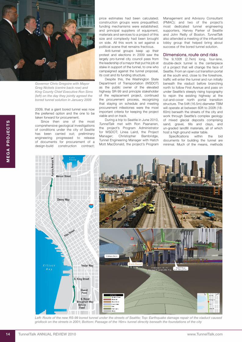
Dimensions, route and risksThe 9,100ft (2.7km) long, four-lane, double-deck tunnel is the centerpiece of a project that will change the face of Seattle. From an open cut transition portal at the south end, close to the foreshore, traffic will enter the tunnel and run initially beneath the viaduct before branching north to follow First Avenue and pass on under Seattle’s steeply rising topography to rejoin the existing highway at the cut-and-cover north portal transition structure. The 54ft (16.5m) diameter TBM will operate at between 60ft to 200ft (18-60m) beneath the streets of the city and work through Seattle’s complex geology of mixed glacial deposits comprising sand, gravel, tills and clays, and un-graded landfill materials, all of which host a high ground water table.
Specifications within the bid documents for building the tunnel are minimal. Much of the means, methods
Governor Chris Gregoire with Mayor Greg Nickels (centre back row) and King County Chief Executive Ron Sims (left) on the day they jointly agreed the bored tunnel solution in January 2009
Left: Route of the new RS-99 bored tunnel under the streets of Seattle; Top: Earthquake damage repair of the viaduct caused gridlock on the streets in 2001; Bottom: Passage of the 16m+ tunnel directly beneath the foundations of the city

Direct by Design
WOULD YOU LIKE TO SEE
YOUR ADVERT HERE?Advertising opportunities in this annual printed review from TunnelTalk will record your
contributions to the major events and developments of the year in a souvenir issue,
while complimenting your web advertising campaigns.
Copies will be distributed at the main tunnelling conferences and events through 2012
including the ITA World Tunnel Congress in Bangkok in May and the NAT in Indianapolis
in June. The Review is also available to those who order copies via our website.
Web advertising on TunnelTalk.com:
In addition to the Annual Review, advertising on the TunnelTalk web magazine is prominent, fast, direct and effective. It offers all the exciting possibilities of electronic web-publishing for getting your message to our web readers and visitors and includes a direct hotlink to your website and its wealth of company information.
Generate your own customized web ads to take advantage of the site’s format and style and to use any or all of the web options available including full screen presentations, animation, sound, video clips or a combination of all. Let your imagination be your guide. Of the infinite web advertising possibilities, TunnelTalk.com currently holds examples of Panorama, Poster, Banner, and Logo size presentations, some with animation and sound. With elements supplied we can build the presentation for you.
Access to TunnelTalk.com is free. No logins, passwords; no subscriptions or registrations. Our host organization logs all site traffic and these data too will be made available to support our advertising opportunities and rates.
Contact us now for more information about advertising opportunities for both the TunnelTalk 2011 Annual Review and website
Contact Advertisement Manager Binda Punj on: Tel: +44 33 0001 1287 and by email at: [email protected]
ASK ME ABOUT OUR PACKAGE DEALS ONLINE AND IN THE REVIEW

ME
GA
PR
OJ
EC
TS
TunnelTalk AnnuAl Review 2010 www.TunnelTalk.com18
For London’s mega Crossrail project, 2010 was a positive year. It maintained its public and private
funding commitments, progressed its realization through the detailed design phases, saw the start of early enabling works and culminated at the end of the year with award of the major tunnelling contracts for 21km of large diameter tunnelling beneath the heart of the capital.
As Europe’s largest civil engineering infrastructure project of the moment, the total 118km integration rail project links Maidenhead in the west through the central core under London to Shenfield and Abbey Wood in the east. At an estimated investment of £14.5 billion (about US$24 billion), the demanding, intense programme of tunnelling and surface civil engineering construction is scheduled to be complete and ready for the start of commercial service in 2018. Arriving at the point of seeing main tunnelling activity begin in 2011-12 was the story of 2010.
Historical startCrossrail was first proposed as part of the Central London Rail Study in 1989. Through the intervening years, the main responsibility of managers was to protect the project’s underground easements
and alignments, a responsibility that was managed exceptionally well. In 2003, the organization Cross London Rail Links was formed to advance the project. Douglas Oakervee OBE was appointed Executive Chairman in 2005 to guide a hybrid bill through Parliament and gain powers needed to construct the new rail system.
In 2007 Prime Minister Gordon Brown committed public funding to the project, estimated at that time at £15.9 billion. This lead to Parliament passing the Crossrail Act in July 2008. In December 2008, Cross London Rail Links became a wholly owned subsidiary of London’s public transit authority, Transport for London (TfL) as one of the project’s two public authority sponsors with the UK Government’s Department for Transport. At that time it also changed its name to Crossrail Limited.
With the majority of funding committed from public sources, there are also private enterprise contributors. • £230 million from BAA, owner of
Heathrow Airport, to include an underground spur link into the airport;
• £350 million from the City of London as a major beneficiary of the project;
• £150 million from the Canary Wharf Group to take on responsibility for design and construction of Crossrail’s station at Canary Wharf; and
• agreement with Berkeley Homes to fund design and construction of the Crossrail station box at Woolwich as a significant benefit to its urban housing development.Other sub-partners in the project
include London Underground, Network Rail, the Docklands Light Rail, the major utility companies, and the owners of private property that is directly impacted by the new Crossrail structures.
With Royal Assent in hand, the project began mobilization of its management structure. A new Crossrail Board of six Non-Executive Directors was appointed; Terry Morgan CBE became Executive Chairman, with Oakervee becoming the Non-Executive
Chairman, and Rob Holden CBE, became Chief Executive. Holden, who has since resigned, was formally Chief Executive of London & Continental Railways that built the London section of the Channel Tunnel Rail Link (CTRL) with its Thames River underpass and 19km of twin bored tunnels under North London to the new St Pancras international terminal. Morgan was previously Chief Executive of Tube Lines Ltd, the now dissolved 30-year PPP with London Underground to upgrade the Jubilee, Northern and Piccadilly Underground Lines.
Delivery strategyTo its own core of employed staff, Crossrail engaged two private-sector partners as the best way to recruit the talent and resources needed during the coming years of realisation. After an international procurement process, the £400 million Project Delivery Partner, to help manage construction of the central underground section, was awarded to a consortium of San Francisco’s Bechtel, with Halcrow of the UK and rail engineering group Systra of France, and the £100 million Programme Partner contract, to assist coordination of all the various parts of the massive undertaking, is awarded to Transcend, a joint venture comprising AECOM of the USA, with CH2M Hill of the US and the Nichols Group of the UK. The managers and engineers assigned to these contracts are integrate with the existing Crossrail Programme Team and co-located to the project’s central headquarters that occupy four floors of an office tower in Canary Wharf with capacity for upwards of 1,000 employees.
With the management structure in place, Crossrail began procurement of the project’s detailed design, in particular its core underground alignment beneath London.
Procurement strategyLondon knows well construction of large underground civil projects, completing in recent times the Heathrow Express and the London Underground Jubilee Line
The underground core of the Crossrail project
London prepares for Crossrail
Crossrail Visitor Centre at the heart of the action
in central London
After decades on the drawing board, London is now preparing for start of heavy construction of its multi-billion Crossrail project. Contracts for some 21km of large
diameter twin tube running tunnels and excavation of major underground station caverns will provide throughway for heavy rail services across the capital.
Shani Wallis, TunnelTalk

ME
GA
PR
OJ
EC
TS
19www.TunnelTalk.com TunnelTalk AnnuAl Review 2010
Extension in the 1990s; construction of the underground rail extensions to the new Terminal 5 at Heathrow Airport that opened in 2008; and the 19km of twin tube tunnelling under the northern suburbs of London for the CTRL during the mid-2000s.
Crossrail however is a quantum increase on these previous projects. The alignment is directly beneath the very heart of London; it is estimated at more than £14 billion and calls for 21km of underground route. JLE was £3 billion and CTRL £9 billion and the Crossrail underground route is two to three times the scope of CTRL and JLE.
Different procurement strategies have also been adopted for Crossrail. It is not a design-build or contractor-alternative project as JLE was, nor is it an ‘early contractor involvement’ process, as was used on Heathrow T5. Nor is it a strict 100% design-bid-build procurement as used for CTRL. Instead contractors had the opportunity to value-engineer changes to improve constructability of the works once designed and before construction bids were invited. These ‘optimised contractor involvement’ suggestions are to be incorporated into the final design once the contract is awarded and before construction starts. In this way, explained Chris Dulake, the Project’s Package Manager for Tunnels, Shafts and Portals to TunnelTalk in 2009, “the designers, as well as the contractors, own risk. Engineers will design the works with the evident risks fully appreciated and accounted for, and the contractors will own the risks involved with the methods employed and the construction output.”
Project scope and scaleAfter his successful overseeing of the new airport project in Hong Kong, Oakervee, established a holistic approach to Crossrail to avoid the situation of addressing the same issues in three different ways.
Under the strategy design of all the SCL (sprayed concrete lining) work on the entire project is covered in one package, as is design of all the bored tunnelling needs. In addition, design is applied horizontally across the full project rather than vertically at different structures along the alignment. There is no need for three or four different designs of the segmental linings for example and the full toolbox of SCL design items need not be designed more than once for all the different applications across the project.
Design of the instrumentation and ground movement monitoring require-ments across the central underground section is a major undertaking. With large-scale excavation programmed alongside existing underground infrastructure and beneath iconic landmarks and the fabric of the city on the surface, settlement and its control is a paramount concern. Armed with the monitoring technology of today, working in conjunction with modern TBM and open sequence excavation methods, and supported by advanced techniques of arresting ground movement and controlling surface settlement, Crossrail has set very tight thresholds for excavation volume
losses at 1% maximum and as low as 0.5% in some areas. These are much tighter than the 1.5-2% volume loss design criteria applied for JLE and CTRL.
Design and constructionTo comply with EU competitive tender regulations, Crossrail prequalified designers and contractors and it is via mini-competitive tenders among these that design and construction contracts are awarded.
From 12 firms that prequalified for Design Framework Agreements, contracts were awarded in early 2009 (Table 1).
Prequalified construction groups were announced in mid-2009.
The collaboration between consultants and contractors via the otpimised contractor involvement process became vitally important in mid-2010 when the new Government in the UK announced stringent public spending cuts across all departments. While the Government confirmed a continuing commitment to Crossrail, it had to explore and realise economies and cost savings. The rationalisation process confirmed a saving of almost 9% on the original £15.9 billion budget to £14.5 billion,
Crossrail’s connections at Tottenham Court Road
Table 1. Major design consultants engaged on the Crossrail project
PRogRAMMe PARTneR – Transcend, a JV of AECOM of the USA, with CH2M Hill of the US and the Nichols Group of the UK
PRojeCT DeliveRy PARTneR – Crossrail Central, a team of: Bechtel of the USA with Halcrow of the UK and Systra of France
DeSign PACKAgeS
Contract Package description engaged firm
C100 Architectural Component Design Atkins
C121 Sprayed Concrete Lining Mott MacDonald
C124 Railway Systems & Tunnel M&E Services Mott MacDonald
C131 Paddington Integrated Project Mott MacDonald
C138 Liverpool Street Station Mott MacDonald
C122 Bored Tunnels - Alignment & Track Arup
C134 Tottenham Court Road Arup
C123 Intermediate Shafts Jacobs
C130 Paddington Station Scott Wilson
C136 Farringdon Station Scott Wilson
C152 Pudding Mill Lane Scott Wilson
C132 Bond Street Station WSP UK Ltd
C140 Whitechapel Station Hyder
C154 Victoria Dock Portal Hyder
C150 Royal Oak Portal Capita Symonds
C156 North Woolwich & Plumstead Portal Capita Symonds
C170 Communications & Control System Parsons Brinckerhoff

TunnelTalk AnnuAl Review 2010 www.TunnelTalk.com22
First tube through at last!
Ground freezing applied to manage the Mölleback
On June 8, 2010, the Hallandsås project celebrated a mini-breakthrough of major significance. A
mid-tunnel breakthrough completed a north-south connection through the mountain. Not a full TBM diameter breakthrough but connection with a pilot heading that marks safe passage through the most complex and risk-filled zone of the alignment.
Measuring 250-300m, the Mölleback Zone (MBZ) of the 8.6km long tunnel is a tectonically faulted zone of highly variable and altered rock with a high ground water content. “The zone is made up of thin layers of different types of weathered rock and soils all lifted vertically,” explained Dr Robert Sturk, Technical Manager for the Skanska-Vinci HB construction joint venture. “A high water table in the 130-140m of cover produces water pressures of about 11-13 bar at the tunnel horizon.”
The 10.6m o.d. Herrenknecht TBM being used to tackle this attempt to conquer the Hallandsås challenge is designed to withstand 15 bar in the static mode, 8 bar in continuous dynamic mode, and 13 bar for short stretches of a few meters in dynamic mode. “Almost 95% of the tunnel is in hard abrasive rock but it is highly fractured and the high water content results in high volume water ingress at high pressure,” said Sturk. “We used the machine in the closed slurry mode for a time at the beginning but the wear on the cutterhead and the demand on the systems was very high, so we have instead progressed mostly in the open mode
with extensive pre-grouting to control the water. The Herrenknecht TBM is fitted with the ability for extensive grouting ahead of the tunnel face to provide a treated zone into which an advance of five to ten 2.2m wide rings of precast lining can progress before the grouting cycle starts again.”
This method has served TBM progress
well through the 5km it has advanced from its start at the south end of the tunnel, but it was not considered capable of controlling the water content in the essentially flowing materials of the MBZ. Here the more effective pretreatment of ground freezing, installed horizontally from a pilot tunnel, was adopted.
A full diameter rail tunnel now pierces the Hallandsås ridge in Sweden. On Wednesday
August 25, 2010, the one 10.6m diameter Herrenknecht TBM working on the twin tube railway tunnel broke through into a 1.5km reach of drill+blast excavation completed under a previous contract.
The breakthrough closes out nearly four and a half years of continuous round-the-clock work to complete the 5km segmentally-lined, TBM tunnel between 1.5km and 2km of drill+blast work from the north and south portals respectively. The TBM will now be dismantled and withdrawn from its in-tunnel breakthrough, and returned to the face of the south portal drill+blast heading to repeat the process for the parallel tube.
“This is a great day for everyone working on the project and a major step towards eliminating the greatest bottleneck on the West Coast Line,” said Per Rydberg, Project Director at the Swedish Transport Administration on the occasion of the celebrations.
The twin tube, double track rail tunnel has been under construction since the early 1990s and has overcome serious geological, political, technical and environmental setbacks.
Controlling ground water and working through exceptionally difficult geological and logistical conditions has charted construction of the Hallandsås project. Work started back in the early 1990s when an open hard rock machine was procured and assembled but abandoned after only some 10m as being unsuitable for the job. In 1996 a new contract was awarded to Skanska for a drill+blast operation on four headings. This advanced for about 1.5km from the north portals and about 2km from the south before it too was terminated over an environmental issue. The toxic catalyst of a two-part chemical grout being used to control water ingress ran freely from the tunnel heading and contaminated local water ways, poisoning wildlife and cattle drinking from the rivers and creeks.
All work was suspended and a remediation contract was then let for the years 1998-2000 to line the drill+blast lengths of tunnel and hold all secure while the client, the Swedish National Railways, and the Government decided the fate of the project. In 2003 it was decided to let another contract, which Sweden’s international construction company Skanska together with French company Vinci Grand Projects won
ME
GA
PR
OJ
EC
TS

ME
GA
PR
OJ
EC
TS
23www.TunnelTalk.com TunnelTalk AnnuAl Review 2010
for a new TBM attempt, this time using a closed pressurized system with a precast concrete segmental lining.
The 10.6m o.d. Herrenknecht TBM stated from the end of the drill+blast heading at the south portal in early 2006 and has worked pretty much 24 hours/day, 7 days/week since then to connect the 1.5km of drill+blast tunnel from the north portal in August.
Even operation of the Herrenknecht TBM procured for this successful attempt as one of the most geotechnically difficult projects of all time, has had to undergo changes. Designed to operate as a slurry Mixshield and withstand hydrostatic pressures of up to 15 bar, the method was changed to open mode TBM excavation with extensive pre-excavation grouting to control the high volume, high pressure ground water conditions.
Through the 250-300m long Mölleback Zone (MBZ) neither technique was considered capable of success and instead the entire zone was pre-supported with ground freezing. The machine intersected the freeze zone in mid-May 2010 and it took 14 days to drive through the frozen zone, cutting through the glass-fibre feeze pipes as it advanced. For the last 600m, the 10.8m diameter TBM excavated the collar of rock that surrounds the central pilot heading, breaking through into the completed drill+blast heading.
Completing the Hallandsås rail tunnel, no matter its technical challenges and financial costs, is vital to the operation of rail services in Sweden. The country’s important West Coast Line is currently 85% double track. The sharp curves on the single track over the Hallandsås ridge
constitutes a serious bottleneck. When the double track through Hallandsås is completed, a doubling of rail freight tonnage will be possible, and the number of trains per day can increase from the current number of four to 24 per hour. A double track railway is said to correspond to a 16-lane highway in capacity.
The first trains are expected to pass through Hallandsåsen in 2015. “We have a well-functioning method and have gained valuable experience that we bring with us for completing the twin TBM drive,” said Anders Rehnström, Project Director for the project’s construction joint venture Skanska-Vinci.
The first TBM hole through is achieved ahead of the anticipated mid-September 2010 date and the second drive can be expected to come in earlier than programmed. The worst of the unknown is now largely behind them. n
After years and many attempts of battling extreme geological
conditions, efforts on the famed Hallandsås project are winning. In June 2010, the Herrenknecht TBM
connected with the Mölleback Zone pilot tunnel and achieved full
diameter breakthrough in August.
Hallandsås celebrates first tunnel finish
Shani Wallis, TunnelTalk
The various phases of installing the freezing through the MBZ started in January 2006 (Fig 1). By the time the TBM arrived, a collar of frozen ground about 4-6m thick around the 8m diameter circle of freeze pipes was in place. The freezing circuit was discontinued in mid-May and it took 14 days, working around the clock, to get through the zone and achieve breakthrough with the pilot heading.
“This was a truly significant achievement,” said Sturk. “We now have about 600m to go to break through completely in about mid-September.”
Only one TBM could be used on the twin tube project. Tight restrictions imposed on the project by the Swedish Government’s environmental protection agencies to control ground water flows from the headings limited excavation to only one tube at a time.
Knowing the risks of the MBZ ahead of them, the construction team decided to drive an in-line pilot heading of about 600m from the face of the north portal drill+blast headings to the start of the MBZ and from there install the 100m of full-circle ground freezing. With the ring of freeze pipes set at an 8m diameter profile within the 10.6m o.d. profile of the TBM, a new system of glass-fibre freeze pipes was developed by the joint venture and specialist Austrian drilling company Insond so that the TBM could grind through these as it progressed.
“Getting through this MBZ zone was one of the high risk elements on the
project,” confided Dr Terry Mellors, adviser and monitor of the project for its insurers. “To have come through successfully is a benchmark achievement technologically, and an outstanding milestone for the project.”
Driving through the frozen zone was said to have been highly successful according to Sturk. “Of course there was still considerable risk involved - the effectiveness of a freeze can never be guaranteed - but it proved to be very secure. There were no incidences of serious concern. We will now repeat, basically, the whole routine to complete the second tube.”
Hallandsås is among the benchmark projects in the development of TBM
technology to work under high ground water content and high ground water pressures. The Herrenknecht machines designed for the Arrowhead project in California began this cycle of development and the Herrenknecht system procured for the Lake Mead water intake tunnel project in Nevada is the next in the evolution of the technology. n
References• Arrowhead: Clawing success from the
extreme - TunnelTalk, Dec 2007• Final breakthrough for Arrowhead -
TunnelTalk, Aug 2008• Lake Mead TBM designed for the extreme
- TunnelTalk, Nov 2009
Surrounded by frozen ground in the pilot tunnel

DIS
CU
SS
ION
FO
RU
M
139www.TunnelTalk.com TunnelTalk ANNUAL REVIEW 2011
It is hard to say when the era of the mega tunnelling machine started. There was a time when 10m in diameter
was considered the largest likely, or indeed possible. But whatever was once considered the technological limit, there are now many dozens of machines exceeding the 10m diameter size. This, in turn, increases the benchmark for current mega-machine criteria.
Discussions in the past have considered the manufacture of the main bearing a limiting factor but these can now be designed and delivered in sections and built into machines on site. A limit to the
size and load of a single component to job sites is also a controlling barrier.
Another consideration is application of the thrust needed to advance such mega machines. For soft ground TBMs, there is a controlling factor on the number and power of thrust rams needed to apply the force, as well as the surface area and ability of the precast concrete lining segments to accept the load.
Overcoming the tremendous torque generated by the massive cutterheads as they excavate the face is perhaps the most limiting factor today, together with the practicalities of operating and maintaining
such enormous machines.
References• New Zealand joins the mega-TBM
tunnelling set - TunnelTalk, August 2011
• Russia confi rms order for largest TBM ever - TunnelTalk, Aug 2011
• A second mega-TBM river crossing for Nanjing - TunnelTalk, Aug 2011
• Robbins TBM rolls into hard rock history - TunnelTalk, May 2011
• Seville SE-40 Highway Tunnels - TunnelTalk, April 2010
• Giant TBM accepted and heading for Italy - TunnelTalk, Dec 2010
• Japanese machine for Seattle’s Alaskan Way mega drive - TunnelTalk, July 20011
Tracking the world’smega-TBMs
TunnelTalk reporting
Start date
Country Project TBM manufacturer Diameter
1994 Japan Trans Tokyo Bay Highway Tunnel 8 machines3 Kawasaki, 3 Mitsubishi, 1 Hitachi, 1 IHI
14.14m
1997 Germany Hamburg 4th Elbe River Highway Tunnel 1 Herrenknecht Mixshield 14.2m
2000 The Netherlands Groenehart double-track rail tunnel 1 NFM Technologies 14.87m
2001 Russia Moscow Lefortovo Highway Tunnel 1 Herrenknecht MixshieldEx-Elbe project machine
14.2m
2004 Japan Tokyo Metro 1 IHI EPBM 14.18m
2004 China Shangzhong Road Subacqueous Tunnel, Shanghai
1 NFM TechnologiesEx-Groenehart machine
14.87m
2004 Russia Moscow Silberwald Highway Tunnel 1 Herrenknecht MixshieldEx-Elbe project machine
14.2m
2005 Spain Madrid Calle 30 Highway Tunnels 2 machines1 Herrenknecht, 1 Mitsubishi
15.2m15.0m
2006 Canada Niagara Water Diversion Tunnel* 1 Robbins hard rock gripper TBM Rebuilt Manapouri tailrace tunnel machine
14.4m
2006 China Shanghai Yangtze River Tunnel 2 Herrenknecht Mixshields 15.43m
2006 China Jungong Road Subaqueous Tunnel, Shanghai
1 NFM slurry shield Ex-Groenehart machine 14.87m
2007 China Bund Tunnel, Shanghai 1 Mitsubishi EPBM 14.27m
2008 China Nanjing Yangtze River Tunnel* 2 Herrenknecht Mixshields 14.93m
2009 China Yingbinsan Road Tunnel, Shanghai 1 Mitsubishi EPBM Ex-Bund Tunnel machine 14.27m
2010 China Qianjiang Subaqueous Tunnel, HangzhouSecond tube currently under construction
1 Herrenknecht Mixshield Ex-Shanghai Yangtze River Tunnel machine
15.43m
2010 Spain Seville SE-40 Highway Tunnels* 2 NFM Technologies EPBMs 14.00m
2011 Italy A1 highway tunnel* 1 Herrenknecht EPBM 15.55m
2011 China Hong Mei Road, Shanghai 1 Herrenknecht Mixshield 14.9m
2011 China Weisan Road Tunnel, Nanjing* 2 IHI/Mitsubishi/CCCC slurry TBMs 14.93m
2011 USA Alaskan Way elevated highway replacement tunnel*
1 Hitachi Zosen EPBM (Letter of intent) Approx 17.6m (58ft)
2011 Russia Orlovsky Tunnel, Saint Petersburg* 1 Herrenknecht Mixshield Engineering started 2009, order confi rmed 2011
19.25m
2011 New Zealand Waterview motorway connection tunnel, Auckland*
1 EPBM to be ordered Approx 14m
* TunnelTalk reference below
CO
MP
AN
Y N
EW
S
179
www.TunnelTalk.com
TunnelTalk ANNUAL REVIEW 2011
Paula Wallis and Peter Kenyon, TunnelTalk
Bad debts and downturn left Halcrow
exposed to buy out by CH2M HILL
The effects of the global economic
downtown plus political problems,
social unrest and bad debt in the
middle East are root causes for the high
profi le take over in November 2011 of
British consultant Halcrow by CH2M Hill
of the United States.
Under the agreement CH2M HILL
bought 100% of the issued and to be
issued share capital of Halcrow Holdings
Limited for £124 million ($194 million) in
cash and took over the fi rm’s outstanding
debt and pension liability for a total
reported purchase value of more than
$356 million. With the addition of Halcrow, CH2M
HILL will more than double its international
presence to almost 30,000 employees
globally with more than 11,000 outside of
the US. The Colorado-based employee-
owned company reported $3.6 billion in
worldwide revenues for 2010. Halcrow
is currently owned by the Halcrow Trust
and employee shareholders and employs
about 6,000 people in about 98 offi ces
in 70 countries around the world. It last
reported a turnover of about £500 million
for 2009. Martin Knights, Global Director of
Tunnelling for Halcrow, is upbeat about
the move. “My initial reaction, along with
the 350 strong tunnelling and geotechncial
staff that l represent worldwide, is that
the whole will be greater than the sum
of the parts and that the two companies
complement each other well.”
Peter Gammie, Chief Executive of
Halcrow said that the board’s decision to
approach CH2M HILL to discuss the sale
“refl ects an increasing trend” in the global
engineering industry. It “will create a very
signifi cant value proposition for clients
[and] where we share geographies, we
are reinforcing one another rather than
duplicating.” He said the buyout comes
after having worked with CH2M-HILL
on numerous projects going back many
years. The two companies are currently
working on the Thames Tideway project
in London where CH2M HILL is the
project’s program manager and Halcrow
a subconsultant on the $6 billion sewage
interceptor and storage tunnel. Both are
also working on London’s £14.5 billion
Crossrail project.
CH2M HILL Chairman and CEO Lee
McIntire called the acquisition a game
changer for the company’s clients. “Our
global footprint will be deeper and our
bench strength will be even more robust.
Our two fi rms are ideally suited in terms
of cultures, markets, geographies, and
we have a shared long-term vision for the
future,” he said.
The effects of the global economic
downtown plus political problems, social
unrest and bad debt in the Middle East
are laid bare in Halcrow’s 2010 annual
report with analysts seeing little prospect
for this year’s fi gures to buck the trend. In
the end, even a ruthless two year round of
job cuts, to what Halcrow’s management
called a “new slimmed down corporate
structure”, were not enough to see the
business maintain its independent status.
At the end of 2008, Halcrow Holdings
employed more than 7,300 staff, 6,100
of them in a professional and technical
capacity. Two years later the workforce had
shrunk by 1,000, at a cost in redundancy
packages of nearly £10 million.
To put this in context, Halcrow’s
profi t after tax in the calendar year to
31 December 2010 was £7.08 million.
Alarmingly for the company, operating
costs, made up mostly of wages and
salaries, remained virtually unchanged at
the height of the restructuring programme.
Turnover crashed by 8.1% year-on-
year from a record-breaking £506.5 million
at the end of 2009 to a disappointing
£465.48 million by the end of last year
(2010). Meanwhile pre-tax profi ts slipped
to £8.8 million, barely half that of 2009,
and more than £3 million less than those
recorded in 2006 (Table 1).
The 2010 annual report tells a story of
a fi rm that, not unlike its competitors, was
suffering badly in the UK and USA core
markets that accounted for more than
half of all business, while at the same time
experiencing rapid growth in the emerging
markets of Latin America and Australasia.
Unfortunately for Halcrow, a 30%
increase in revenues from these secondary
markets represented only an additional
£10 million to the balance sheet.
Revenue from the Middle East,
Halcrow’s second biggest market by
some distance after the UK, declined
by £35 million. Between 2009 and 2010
income from this region fell from £148.2
million to £113.5 million (23.5%).
As the business summary in the 2010
annual report put it: “Behind this year’s
fi gures lies a complex story of strongly
differing performances in different markets
around the world. Our new, slimmed-
down corporate structure has removed
signifi cant costs from the business and
made us more agile and responsive to
clients, but globally, conditions continue
to be challenging as major infrastructure
opportunities were postponed or
cancelled.”
A UK government public sector
spending squeeze contributed to falling
revenues in the UK while in the US
“challenging conditions” were not helped
by the cancellation of major contracts.
There was no news of a new name
for the merging major players, but for
Halcrow it will be end of the independent
entity since it was founded in 1868. As well
as the Crossrail and Tideway projects in
London, the company is heavily invested
in the Middle East and is working on
tunnelling projects for the metros in Hong
Kong, Kuala Lumpur and Rio de Janeiro,
the high-speed rail proposal between Sao
Paolo and Rio de Janeiro in Brazil, and
water projects in Argentina.
Signature projects for CH2M HILL
include the Singapore Deep Tunnel
Wastewater Program, the London 2012
Olympic and Paralympic Games Program,
the Panama Canal expansion program,
and the sustainable MASDAR City in the
United Arab Emirates.
With cash fl ows under threat, moves
to restructure the company and cut
costs from the balance sheet made
Halcrow ripe for takeover or sale. Under
the terms of the takeover, share-holding
employees and directors will be entitled
to £5.64 for every share they hold (or be
entitled to shares to equivalent value in
the new company). This is far more than
the 395.2p weighted average share price
value just nine months ago.
Between them seven of the
company’s eight executive directors have
interests in 392,028 of Halcrow’s 25
million shares in the form of share options
at a range of prices between £1.95 and
£4.03. According to the 2010 annual
report, Chief Executive Peter Gammie, for
example, has options on 75,287 shares
that may be exercised at an option price
of £2.61, exercisable between August
2010 and August 2017.
But by far the vast majority of shares
in the company are held by the company’s
employees, all of whom look set for
a windfall when CH2M HILL is fi nally
authorised to pay $193 million for the
balance of all the shares.
References• Roll out of fi nal tunnel contracts for
Crossrail - TunnelTalk, March 2011
• Lee Tunnel start for London’s Thames
Tideway supersewer project - TunnelTalk,
March 2011
• ARC cancellation hits industry hard -
TunnelTalk, Nov 2010
• Two extremes in one for Singapore’s DTSS
- TunnelTalk, March 2005
15
www.TunnelTalk.com TunnelTalk ANNUAL REVIEW 2011
Agreement in April 2011 of its
billions of Euro in funding marked
the offi cial start of Europe’s most
ambitious infrastructure project. EU
Transport Commissioner Siim Callas, with
the Austrian and Italian transport ministers
Doris Bures and Altero Matteoli, gathered
with other offi cials in Innsbruck, Austria,
to celebrate an agreement that secures
the estimated €9.7 billion (US$13.8 billion)
capital investment for the Brenner Base
Tunnel and launches its construction
project realisation.
Austria and Italy have agreed to share
the cost of the project with additional
funding from the European Union. While the
approach of Austria and the EU is to give
periodic assessments and assurances on
funding for the trans-Alpine link, the Italian
Government approved its contribution for
the full duration of the project, in November
2010. About 30% of the total budget is to
be met by the EU with the balance funded
equally between Austria and Italy.
The 55km (34 mile) mega-tunnelling
project through the Alps to link Innsbruck,
Austria with Franzensfeste (Fortezza) in Italy
is a cornerstone of the EU’s Trans-European
Transport Network (TEN-T) Priority Project
1 that proposes a high capacity rail route
from Berlin in the north to Palermo on Sicily
in the south. The twin tube tunnel will link
directly to an existing rail bypass tunnel
around Innsbruck to become the world’s
longest railway tunnel complex.
The Innsbruck bypass links further
to 66km of new rail capacity through the
Lower Inn Valley to the German border. The
majority of the fi rst 40km of the line to Kundl
lies underground in lengths of TBM and
NATM mined tunnels. As part of the TEN-T
Priority Project, the Lower Inn Valley project
also received EU funding support.
Preliminary work on the massive
Brenner Baseline tunnel undertaking
began at both portals with exploratory
headings. These are designed to
investigate characteristics and behaviour
of rock conditions likely to be encountered
to minimise risks and verify budget cost
calculations. The exploratory tunnel will be
used for drainage and eventually as the
service tunnel. It is also planned to carry
power and data cables.
In Austria the Strabag - Porr JV is
advancing drill+blast excavation of a
5.6km long exploratory tunnel towards a
known fault zone. On the Italian side, SELI,
as part of a consortium with Pizzarotti,
Bilfi nger Berger, Alpine Meyreder, Beton-
und Monierbau, Jaeger, Collini Impresa
Costruzioni, and Societa Italiana per
Condotte d’Acqua, completed a 10.5km
TBM bored and segmentally lined tunnel
using a 6.3m Aker Wirth double shield
machine. Started in Spring 2008, the TBM
battled through fault zones and against
water pressures of up to 27 bar to hole
through into an underground chamber at
the end of a 1.8km long intermediate adit
at Mauls (Mules). With work now set to progress on the
Brenner Base Tunnel in earnest, the BBT,
Brenner Basis Tunnel SE client organisation,
has had discussions with tunnelling
teams that have recently completed deep
mountain TBM and drill+blast excavation
for the 57km long Gotthard Base Tunnel,
in Switzerland. Valuable lessons and
the actual experience of this fi rst deep
tunnelling project into the Alpine massive
Patrick Reynolds for TunnelTalk
A green light for the Brenner Base Tunnel to push ahead into the main building phase
came from Austria’s approval of fi nancing at the beginning of February 2011. Italy, its
partner, gave its commitment to funding for the bi-national rail link through the Alps in
late 2010. With challenging geology facing tunnellers, work has started with an explora-
tory tunnel and packages for the main running tunnels are due to be let for a start of
their construction in 2016. Patrick Reynolds reports on the latest developments on one
of Europe’s most important and far-reaching transport infrastructure projects.
Drill+blast of the Innsbruck-Ahrental
exploratory tunnel package
Brenner Baseline connection: Let the works begin!
ME
GA
PR
OJ
EC
T
47
www.TunnelTalk.com
TunnelTalk ANNUAL REVIEW 2011
Following a series of setbacks, the
TBM on the Lake Mead Intake
No 3 project outside Las Vegas,
Nevada, fi nally got going in September
2011. The shield and the cutterhead of
the Herrenknecht Hybrid Mixshield were
lowered into the access shaft sitting on site
for almost two years.
The original 350ft (106m) starter tunnel
was abandoned after infl ows of muck
and water derailed excavation on three
separate occasions.
“We are feeling better about the
project,” said Jim McDonald, Project
Manager for the Vegas Tunnel Constructors
JV of Impregilo and its US subsidiary, SA
Healy. “The new alignment for the starter
tunnel turned out exceptionally well. The
ground was just a world away from the
conditions we had encountered on the
original alignment.”
At the end of June 2010, an infl ow of
more than 5,000m3 of water and material
fl ooded the 60m long TBM launch chamber
and rose about 46m in the 182m deep
access shaft. A second and third event
happened in October and December. In
January 2011, a decision was made to
change the alignment for better ground.
“The original alignment was plugged
with grout and concrete and a new
alignment veered off at a 23° angle to
navigate around the unstable area,” said
Marc Jensen, Engineer for the Owner,
Southern Nevada Water Authority.
Excavation on the new starter tunnel,
which is at the same depth as the original,
began in February this year and was
completed in late July.
“Excavation was all drill+blast, but
we did install a pipe canopy pre-support
system for about two thirds of the 113m
length because of the uncertainty,” said
McDonald. “It is harder to start the canopy
installation when it is too late so we started
early as a precaution.”
“It was blocky fractured ground, but
it did not have the same loose unstable
material encountered on the original
alignment,” said Jensen. “Progress was
slow but steady. The starter tunnel is
about 100ft longer than the original, to
accommodate the complication of having
to assemble and launch the machine on
the angle off the assembly chamber.”
With the starter tunnel complete the
Herrenknecht TBM, that arrived on site
October 2009, will take over excavation of
the 4.8km tunnel to an intake shaft on the
bottom of Lake Mead about 91m below
water level. Capable of converting rapidly
from an open-faced system to a closed
pressurized system, it will be asked to
withstand potential hydrostatic pressures
of up to 17 bar.
The TBM will excavate several
thousand feet before rejoining the original
tunnel alignment for a target of the same
position and depth.
“It sure was a tough start, but we
are optimistic that the worst is behind
us,” said McDonald. “We have probed
ahead of the starter tunnel end wall with
another horizontal core hole and we should
have a pretty good area for launching the
machine.” Construction of the $447 million
design-build contract, with Arup as
lead designer, began in March 2008
with the access shaft on Saddle Island.
Brierley Associates designed the
conventional excavations, MWH/CH2M-
Hill JV prepared the GBR, and Parsons
is providing Program Construction
Management. “The realignment and the associated
differing site condition costs totaled about
$44 million, some of which we will recover
from our builders risk insurance policy,”
said Jensen. “The contractor did agree
to some responsibility and some risk
and that was all included in the agreed
amount.” Despite all this Jensen said
the relationship between the Owner and
Contractor remains strong and possibly
better than ever.
The contractor estimates it will take
about three months to assemble the TBM
for an expected launch date at about the
fi rst of the year. “Because the shaft is so
deep, we are using a strand jack system to
lower the TBM and its components so it is
a little slower than some, but it is steady,”
said McDonald.
Slow and steady may be a welcome
change considering the tumultuous start
that has pushed substantial completion
out to May 2014, and a challenging drive
still to come.
References• Lake Mead suffers another setback -
TunnelTalk, Jan 2011
• Inundation at Lake Mead Intake No 3 -
TunnelTalk, July 2010
• Lake Mead TBM designed for the extreme -
TunnelTalk, Nov 2009
Long wait over forLake Mead TBM
Paula Wallis, TunnelTalk
Cutterhead lowered for assembly (By
SNWA)
Lake Mead Intake No 3 revised alignmentAerial of the working site
Realigned starter tunnel progress
97www.TunnelTalk.com TunnelTalk ANNUAL REVIEW 2011
Groups from China, Korea and Japan will join the fray of the Swiss Challenge process with
local promoter Gamuda-MMC to build the underground section of Kuala Lumpur’s new mass transit line.
Estimated at some MYR12 billion Malaysian Ringgit (about US$3.8 billion), the underground infrastructure comprises 9.5km of twin running tunnels and seven underground stations as the central section (Fig 1) of the capital’s new MYR50 billion (US$16 billion) Klang Valley Mass Rapid Transit line of 51km and 35 stations from Sugai Buloh in the northwest to Kajang in the southeast (Fig 2).
The international contenders for the underground works are groups led by Gadang-Hyundai of Korea, Taisei Corp of Japan, China’s Sinohydro Group, and the China Railway Corp. As the original promoter of the new line, Gamuda-MMC Corp was appointed as the Government’s Project Delivery Partner in December 2010 and as such, was disqualifi ed from construction of the line, except for the underground section. Competitors for the underground works were required to satisfy a stringent set of prequalifi cation criteria.
As the most experienced tunnel construction group in Malaysia, following its successful SMART storm water and road tunnel project in Kuala Lumpur in the early 2000s and the Berapit tunnel on the Ipoh-Padang Besar railway line upgrade in 2010, Gamuda-MMC is presented the opportunity to bid for the underground section via the Swiss Challenge method of procurement. As part of its promotion,
Gamuda-MMC presented the preliminary design and contract principles for the project. Against this, competitive counter-proposals are invited, after which Gamuda-MMC will have the opportunity to exercise a Swiss Challenge right to either equal or better the preferred proposal.
Project scope and managementAs well as the central underground section, the new line comprises at-grade and elevated lengths either side, for a total length of 51km and 35 stations.
Central Government approved the estimated MYR50 billion (US$16 billion) total cost in December 2010. It is the largest ever infrastructure development for Malaysia In September 2011, the MRT Corp was established by the Ministry of Finance to develop the line.
MRT invited design-build proposals for the underground works from the four competing groups for a closing date at the end of January 2012 and towards an award contract by mid-2012. In the meantime eight contract packages for the surface and elevated works were tendered to local contractors in September 2011 and construction activity along the line has started.
Preliminary design of Gamuda-MMC’s proposal for the underground works anticipates eight, or perhaps 10, TBMs to excavate the 9.5km long twin tube running tunnels within a tight construction period that has the line operating (according to Government announcements) by 2016. For the SMART tunnel, in the same area and
through the same geological conditions, Gamuda-MMC used two 13m diameter Herrenknecht slurry Mixshields.
Gus Klados, who worked on the SMART tunnel for Gamuda-MMC, has returned to Kuala Lumpur and the JV to work on the MRT project as nominated Head of Underground Works should Gamuda-MMC exercise a successful Swiss Challenge. Don Hall, who was tunnel construction manager for Gamuda-MMC on the SMART project, would also join the MRT underground construction project.
For the MRT owner organisation, Datuk Azhar Abdul Hamid has been appointed the Chief Executive Offi cer and Marcus Karakashian is recruited from Singapore to lead its management and technical team. Ian Thomas moves from his previous engagement on the Gautrain in South Africa to be Project Director of the MMC-Gamuda Project Delivery Partner organisation for the full mass transit line including procurement of all M+E, operating systems and rolling stock.
As many as 130,000 jobs are expected to be generated for construction of the project. To prepare a workforce for the specialised tunnelling and underground construction works contract, Gamuda-MMC with MTA has established a training facility to train workers for the different
tasks involved.
References• Record rail tunnel breakthrough in Malaysia
- TunnelTalk, Nov 2010• Kuala Lumpur opens tunnel Training
Academy - TunnelTalk, Dec 2011
Five compete for Kuala Lumpur’s MRT Swiss Challenge
Shani Wallis, TunnelTalk
Left: Fig 1. Kuala Lumpur’s MRT route under the central business district and right: Fig 2. Full route of the mass transit line
Record-setting sea links open
in China
Shani Wallis, TunnelTalkDrill+blast excavation of
the 16m wide, 12m high,
three-lane cross-section ME
GA
PR
OJ
EC
T
Dignitaries gathered in June 2011
in Qingdao city, 700km south
of Beijing in China, to open the
world’s longest sea-crossing bridge and
its third longest sub-sea highway tunnel.
The 41.5km long bridge and 7.8km long
highway tunnel under Jiaozhou Bay
connect the historic centre of Qingdao with
its economic and technological zones on
Huangdao Island. The twin-tube six-lane highway,
complete with a central service tunnel, is
China’s second undersea highway and
its completion follows that in 2010 of the
6km long Xiamen Xiang in the south-
eastern Province of Fujian. Only the 10km
long Trans-Tokyo Bay highway tunnel
opened in Japan in 1997, and the 7.9km
long Bømlafjord highway tunnel, opened in
Norway in 2000, are longer.
The new link was constructed
within its 47-month schedule and for
a total investment of 4.18 billion Yuan
(approximately $US650 million). The tunnel
is designed for 80km/hr road speeds and
the two main tubes, at some 55m parallel,
are connected every 750-1,000m with a
vehicle cross passage and every 250-300m
with pedestrian cross passages.
The opening ceremony, which marked
the end of what has been a deeply
challenging sub-sea project, celebrated
the achievements of a remarkably small
owner’s organisation of just 20 staff.
“The project adopted the ‘small owner,
big society’ concept of management,”
explained Jenny Yan Jinxiu, a Director of
the China Railway Southwest Research
Institute in Chengdu. “Through the public
bidding process, more than 30 big
companies, including ours, were engaged
for the research, design, independent third
party supervision and construction of the
project.” Further resources from the ‘big society’
were optimised by engaging renowned
experts, scholars and academics from
China and abroad to evaluate each plan
and provide technical support. A number
of large state-owned companies with a
wealth of tunnelling experience were called
in to address potential problems and
solutions. Drill+blast of the two three-lane tubes
and the 7m diameter service tunnel started
in August 2007 from the Huangdaoside,
and in September 2008 from the Qingdao
side. Final breakthrough was achieved in
April 2010. Excavation was complicated by a
relatively shallow 30m of rock overburden
with a maximum 42m of water to mean sea
level; a large excavated cross section for
the two main tubes of up to 16m wide x
12m high and identifi cation of 18 geological
faults, 13 of them in the 4km undersea
section of the 7.8km tunnel.
During construction pre-grouting was
the key element for limiting water ingress.
Controlled blasting, a robust primary
support regime, and continued monitoring
of ground movement and convergence,
ensured safe excavation. “Application of
advanced technology and a well-organised
management system solved all technical
and management diffi culties,” said Yan.
The Governor of Shangdong province,
the Mayor of Qingdao, as well as other
offi cials, attended the ceremony
Grouting cyclesThree programmes of pre-grouting were
developed to cope with the risk of water
infl ows. Full face, systematic pre-grouting
was adopted for zones in which probe
holes indicated high-volume, high-pressure
infl ows and weak surrounding-host rock.
Part-face pre-grouting to stabilise poor
geology in mixed-face cross-sections
saved time and cost, while peripheral pre-
grouting controlled medium volume and
lower pressure infl ows.
To protect the tunnel from a corrosive
environment of high chloride solution
groundwater and high salt content mists
at the portals, the 100-year design-life
specifi cations required the use of C35 high
performance shotcrete and C50 watertight
concrete. Incorporating fl y ash and silica
fume additives increased the concrete’s
strength and thermal-crack resistance,
21
www.TunnelTalk.com TunnelTalk ANNUAL REVIEW 2011
A PREVIEW OF THE TUNNELTALK 2011 ANNUAL REVIEW
DIS
CU
SS
ION
FO
RU
M
139www.TunnelTalk.com TunnelTalk ANNUAL REVIEW 2011
It is hard to say when the era of the mega tunnelling machine started. There was a time when 10m in diameter
was considered the largest likely, or indeed possible. But whatever was once considered the technological limit, there are now many dozens of machines exceeding the 10m diameter size. This, in turn, increases the benchmark for current mega-machine criteria.
Discussions in the past have considered the manufacture of the main bearing a limiting factor but these can now be designed and delivered in sections and built into machines on site. A limit to the
size and load of a single component to job sites is also a controlling barrier.
Another consideration is application of the thrust needed to advance such mega machines. For soft ground TBMs, there is a controlling factor on the number and power of thrust rams needed to apply the force, as well as the surface area and ability of the precast concrete lining segments to accept the load.
Overcoming the tremendous torque generated by the massive cutterheads as they excavate the face is perhaps the most limiting factor today, together with the practicalities of operating and maintaining
such enormous machines.
References• New Zealand joins the mega-TBM
tunnelling set - TunnelTalk, August 2011
• Russia confi rms order for largest TBM ever - TunnelTalk, Aug 2011
• A second mega-TBM river crossing for Nanjing - TunnelTalk, Aug 2011
• Robbins TBM rolls into hard rock history - TunnelTalk, May 2011
• Seville SE-40 Highway Tunnels - TunnelTalk, April 2010
• Giant TBM accepted and heading for Italy - TunnelTalk, Dec 2010
• Japanese machine for Seattle’s Alaskan Way mega drive - TunnelTalk, July 20011
Tracking the world’smega-TBMs
TunnelTalk reporting
Start date
Country Project TBM manufacturer Diameter
1994 Japan Trans Tokyo Bay Highway Tunnel 8 machines3 Kawasaki, 3 Mitsubishi, 1 Hitachi, 1 IHI
14.14m
1997 Germany Hamburg 4th Elbe River Highway Tunnel 1 Herrenknecht Mixshield 14.2m
2000 The Netherlands Groenehart double-track rail tunnel 1 NFM Technologies 14.87m
2001 Russia Moscow Lefortovo Highway Tunnel 1 Herrenknecht MixshieldEx-Elbe project machine
14.2m
2004 Japan Tokyo Metro 1 IHI EPBM 14.18m
2004 China Shangzhong Road Subacqueous Tunnel, Shanghai
1 NFM TechnologiesEx-Groenehart machine
14.87m
2004 Russia Moscow Silberwald Highway Tunnel 1 Herrenknecht MixshieldEx-Elbe project machine
14.2m
2005 Spain Madrid Calle 30 Highway Tunnels 2 machines1 Herrenknecht, 1 Mitsubishi
15.2m15.0m
2006 Canada Niagara Water Diversion Tunnel* 1 Robbins hard rock gripper TBM Rebuilt Manapouri tailrace tunnel machine
14.4m
2006 China Shanghai Yangtze River Tunnel 2 Herrenknecht Mixshields 15.43m
2006 China Jungong Road Subaqueous Tunnel, Shanghai
1 NFM slurry shield Ex-Groenehart machine 14.87m
2007 China Bund Tunnel, Shanghai 1 Mitsubishi EPBM 14.27m
2008 China Nanjing Yangtze River Tunnel* 2 Herrenknecht Mixshields 14.93m
2009 China Yingbinsan Road Tunnel, Shanghai 1 Mitsubishi EPBM Ex-Bund Tunnel machine 14.27m
2010 China Qianjiang Subaqueous Tunnel, HangzhouSecond tube currently under construction
1 Herrenknecht Mixshield Ex-Shanghai Yangtze River Tunnel machine
15.43m
2010 Spain Seville SE-40 Highway Tunnels* 2 NFM Technologies EPBMs 14.00m
2011 Italy A1 highway tunnel* 1 Herrenknecht EPBM 15.55m
2011 China Hong Mei Road, Shanghai 1 Herrenknecht Mixshield 14.9m
2011 China Weisan Road Tunnel, Nanjing* 2 IHI/Mitsubishi/CCCC slurry TBMs 14.93m
2011 USA Alaskan Way elevated highway replacement tunnel*
1 Hitachi Zosen EPBM (Letter of intent) Approx 17.6m (58ft)
2011 Russia Orlovsky Tunnel, Saint Petersburg* 1 Herrenknecht Mixshield Engineering started 2009, order confi rmed 2011
19.25m
2011 New Zealand Waterview motorway connection tunnel, Auckland*
1 EPBM to be ordered Approx 14m
* TunnelTalk reference below
ME
GA
PR
OJ
EC
T
TunnelTalk ANNUAL REVIEW 2011 www.TunnelTalk.com28
Twin EPBM tunnels of 14m diameter lie at the heart of the largest infrastructure project in
New Zealand’s history. Estimated at NZ$1.4 billion, the Waterview Connection highway project in Auckland is integral to completing the city’s Western Ring Route. The project is one of seven Roads of National Signifi cance, identifi ed by the NZTA in 2009 as being vital to the country’s economic prosperity. A completed ring route will reduce dependency on the Auckland Harbour Bridge Highway (SH1) for through traffi c and provide a continuous highway link from the city centre to the international airport (Fig 1).
In August 2011, the project took a major step forward with the selection of the Well Connected group as the preferred partner to join the New Zealand Transport Agency (NZTA) in a modifi ed Alliance partnership to design and build the new 4.8km of six-lane highway. Well Connected comprises contractors and engineers Fletcher Construction, McConnell Dowell, Obayashi Corporation, Beca, Parsons Brinckerhoff, and Tonkin & Taylor, with sub consultant SICE of Spain providing specialist M&E and tunnel operational expertise.
Within the Alliance Team Sumi Eratne, Project Director in NZTA, is responsible for delivery of the project and is the owner’s interface with the Alliance organization; Peter Spies is Project Manager for project procurement and NZTA’s representative within the Alliance Governance Board, and Rob James is Specialist Tunnelling Advisor to NZTA. “Planning of the project goes back several years,” explained Project Director
Eratne. “Various options were studied and the fi nal route beneath Waterview gives rise to the project’s name.”
Procurement strategyAs New Zealand’s largest construction project, the Waterview Connection contract is some four times larger than its NZ$340 predecessor in dollar terms. “To cope with the scale and complexities of the undertaking, we decided early to adopt the Alliance method of procurement,” said Project Manager Spies. “It is the fi fth Alliance that the NZTA has adopted, and is the preferred procurement model for large, complex and risky projects where early collaborative engagement with designers and constructors is vital.”
With the Alliance model all risks are shared and the non Owner participants in the Alliance are incentivised through the ‘pain share – gain share’ concept. “For Waterview we have used also the GBR concept to set limits for the geological risk to be carried by the non Owner participants,” explained Spies, “After agreeing the geological risk limits with the non Owner participants, these have been incorporated in our procurement contract as an Alliance GBR (AGBR).”
GBRs, explained Spies, are best applied to hard-money contracting but NZTA saw the value in the concept for dealing with unforeseen conditions. If the Alliance was to encounter a hard dyke intrusion that holds up TBM advance, for example, the hard cost consequences will be carried by the Owner, with mechanisms in place to ensure no profi teering from the situation by the
contracting companies. “With this clause in place, we were pleasantly surprised that the allocation to risk, in the two Alliance proposals considered was low,” he said.
Another part of the modifi ed Alliance is appointment of a Strategic Review Panel (SRP), which is imilar to a Disputes Review Board, but with the ability to make recommendations rather than rulings. The SRP will have three members - one nominated by the Client, to be fi lled by current NZTA Specialist Tunnel Advisor Rob James; another by the Contractor; and the third an independent chair.
The NZTA has also taken responsibility for providing principal arranged insurance for the undertaking. Given the complexities of the project, a provisional sum was allowed in the tender for public liability, professional indemnity and contract works insurance and the NZTA and the non Owner participants are working with a broker in London to procure all-risks project-wide coverage.
Tunnel specifi cationsThe process of selecting a design-build Alliance partner began in early 2010 when three groups submitted expressions of interest. In November 2010 this was reduced to a shortlist of two, with the selection based on non-price attributes and experience of completing similar-sized contracts and tunnelling projects. The shortlisted groups were the Well Connected consortium of Fletcher Construction, McConnell Dowell, Obayashi, Beca and Parsons Brinkerhoff and a consortium of Leighton Constructors, Fulton Hogan,
New Zealand awardsmega-TBM highway project
Shani Wallis, TunnelTalk
2.5km of minimum 14m o.d. twin tube EPBM tunnelling is required on Auckland’s Waterview Connection project
ME
GA
PR
OJ
EC
T
TunnelTalk ANNUAL REVIEW 2011
www.TunnelTalk.com
26
The world’s largest hard rock TBM received a hero’s welcome in March 2011, following a long and tortured drive that tested the resolve of all involved. No shortage of dignitaries, media and invited guests were present to witness the massive Robbins TBM’s breakthrough, marking the end of excavation on the 10.2km (6.3 mile) Niagara Tunnel for Ontario Power Generation (OPG). Ontario Premier Dalton McGuinty, OPG CEO Tom Mitchell, Strabag CEO Dr Hans Peter Haselsteiner, and Robbins CEO Lok Home were among those present at the celebration as well as hundreds of workers. “It is terrifi c for a civil engineer like me, having started out on such an ambitious project, to see the excavation come to a successful end,” said Rick Everdell who began his career with OPG’s predecessor, Ontario Hydro and has remained with the project almost 30 years through its various incarnations, and rising to the position of Project Director for the client. “The project has certainly had its share of setbacks, including an economic downturn and reorganization of the power industry in the late 1990s. That forced the cancellation of an earlier tender process and reduced the project from its original two tunnels plus a new powerhouse, to the single tunnel. Then there were challenging ground conditions once we got into excavation. Still, after four and a half years of tunneling, the TBM is fi nally at the fi nish line.”
Strabag won the design-build contract in August 2005. Having successfully completed the previous largest ever hard rock TBM tunnel on the Manapouri Hydroscheme in New Zealand about six years earlier, the Austrian contractor was uniquely experienced. Strabag’s Project Manager in New Zealand, Ernst Gschnitzer, would also take the reins at Niagara. But
almost from the start the excavation was hijacked by extensive overbreak that slowed advance rates to a crawl.
Dark days“The most challenging days were in 2007 when the TBM entered the Queenston Formation before the St. David Gorge and at a maximum depth of 140m (459ft),” said Everdell. “Signifi cant overbreak, meter after
meter, essentially blew out the schedule.” John Tait, Project Manager for Hatch Mott MacDonald, OPG’s representative on the project, summed up the mood in those dark days. “Depressing! Absolutely depressing. The Robbins TBM was capable of doing a 1.4m to 1.8m push in about an hour and Strabag was lucky if it accomplished that in a 24-hour cycle. It went on like that day after day for months
Breakthrough ends tortured journey at Niagara
Paula Wallis, TunnelTalk
Who’s whoOntario Power Generation (OPG) ClientHatch Mott MacDonald (USA) Construction ManagementStrabag (Austria)
ContractorAssociated CompaniesILF (Austria) and Morrison Hershfi eld (Canada) Tunnel DesignersRobbins (USA)
TBM supplierRowa (Switzerland)TBM trailing gearBystag (Germany)Concrete lining operationsH+E Logistics (Germany) Continuous conveyor systemCogemacoustic (France) Ventilation systemCastonguary Blasting (Canada) Blasting operationsMcNally International (Canada) Intake structureDufferin Construction (Canada) Grouting gallery at intake siteBermingham Construction (Canada) Cofferdams
Tunnel by the numbersTunnel 10.2km long (6.3 miles)TBM 14.4m diameter TBM (47.2ft)Excavated material 1.7 million m3 (5.6 million ft3)Concrete for liner 400,000m3 (1.3 million ft3)Tunnel capacity 500m3 (1,640ft3) of water per secondPower generation 1.6 billion kilowatt hours annually
Severe overbreak led to alignment change
Robbins 14.4m TBM ends its 10km drive
TB
M R
EC
OR
DE
R
101
www.TunnelTalk.com TunnelTalk ANNUAL REVIEW 2011
In early July 2011, Russian operator company NCC (Nevskaya Concession Company) placed an order with
manufacturer Herrenknecht for a 19.25m Mixshield TBM to excavate a new highway tunnel under the River Neva in St Petersburg. The machine for the Orlovski Tunnel will surpass all previous TBMs in diameter.
On the occasion of the contract signing, Martin Herrenknecht, founder and Director of the German TBM manufacturer, met with Russian Prime Minister, Vladimir Putin, in St. Petersburg who wanted to learn more about the giant machine and its application on the challenging River Neva underpass.
For Herrenknecht, this is the biggest single order in the company’s history and represents a technical challenge that has been in technical engineering design since 2009. Through collaboration with the Russian operator company, NCC, Herrenknecht AG engineers will build a machine of immense proportion.
On its own, the tunnelling shield will weigh about 3,800 tonne and deliver 8,400kW of drive power to the enormous 19.25m diameter cutting wheel. The leap in diameter to 19.25m will enable the machine to excavate an enormous 600m3 of soil per hour. The tunnel face area is more than 50% larger than that for the largest TBMs currently in operation in the world.
A Mixshield is selected as the quickest and safest solution for driving the 1km long tunnel under the Neva in the face of the high groundwater pressures. Under an extremely ambitious timetable, tunnelling is
set to begin in St Petersburg in the Spring of 2013, with the tunnel due to be taken into operation in 2016.
The aim of this new, record breaking TBM tunnel is to provide signifi cant relief in the center of St Petersburg and allow a continuous traffi c fl ow through a city divided by the river. Until today, vehicles have had to use the various bridges in order to cross the River Neva from the city center to the northern districts and the orbital freeway. Most of these are gated bridges that hold up traffi c for passage of shipping on the Volga/Baltic waterway. Valentina Matviyenko, Governor of St Petersburg, explained that the tunnel is required urgently to provide an uninterrupted crossing of the Neva,
especially during the shipping season. The double-deck mega-tunnel will
have a three-lane carriageway on each deck.
The massive Mixshield is the sixth machine built by Herrenkneckt of more than 14m diameter. One of these, a 14.2m diameter Mixshield, has completed two road tunnel projects in Russia, in Moscow, and another is a 15.55m diameter EPBM working on the Sparvo highway tunnel project in Italy.
References• Tracking the world’s mega-TBMs -
TunnelTalk, July 2011• Giant TBM accepted and heading for Italy - TunnelTalk, Dec 2010
Russia confi rms order for largest TBM everHerrenknecht News Release
Prime Minister Putin and Martin Herrenknecht in St Petersburg
PR
OJ
EC
T P
RO
GR
ES
S
79www.TunnelTalk.com TunnelTalk ANNUAL REVIEW 2011
Two Herrenknecht slurry TBMs are poised to begin the short, but challenging soft ground tunnels on
the $7.3 billion East Side Access project to bring Long Island Rail Road services into Grand Central Station in Manhattan, New York.
Offi cials dedicated the 22ft (6.7m) diameter machines, named Tess and Molina by local school children, in March 18. They are tasked with two drives each. Tess will bore the A tunnel, for in-bound trains to Manhattan, and the D tunnel for outbound trains and Molina will complete the yard lead drive to take trains to and from the mid-day storage yard, and the B/C tunnel, which is a contra-fl ow tunnel for inbound trains in the morning and outbound in the evening (Fig 1).
“TBM Molina is in the trench and it is connected up and electrical testing is underway towards an April start,” said Andy Thompson of Hatch Mott MacDonald and Program Manager for construction. “Molina will start with the yard lead tunnel, the longest drive at about 4,000ft (1,219m). When it reaches the reception pit, the shield will be retrieved and the trailing gear backed through the tunnel to start the B/C drive. Once completed, the machine will stay in place until surface track relocation allows sinking of a shaft to retrieve the cutterhead and fi nish the approach structure.”
The second machine is scheduled to launch six weeks after the fi rst, and will drive the 1,900ft (579m) tunnel A fi rst, followed by the D tunnel. The TBM will be
launched in stages to navigate around the piles of an existing bridge that crosses the open cut construction.
The identical slurry machines supplied by Herrenknecht will tackle the most challenging conditions of the entire East Side Access program. Their drives are mostly in soft ground, with mixed faces, boulders, and manmade obstacles, a high water table, low overburden, and the nation’s busiest railroad interlocking junction overhead. The fi rst machine has an additional component to manage. “The fi rst 300ft (91m) of the yard lead drive is in rock,” said Thompson. “A 100ft (30m) interface zone of mixed face conditions follows and the remaining 3,600ft (1097m) is in soft ground with boulders.”
This is one of only a few slurry machine projects to date in the United States and a fi rst the local union New York Sandhog workers. Other Herrenknecht Mixshield projects in the US include, the Pittsburgh North Shore Connector, the Portland CSO projects, and the Brightwater project in Seattle.
Contractor G.T.F., a three-way joint venture comprising Granite Northeast, Traylor Bros, and Frontier-Kemper, won the contract in September 2009 with a bid of $730 million. “We worked to overcome the limited slurry experience by soliciting requests for proposals,” said Thompson. “The team selected includes Traylor Bros as one of the contractors in the country with extensive soft ground TBM experience.”
Thompson said the TBMs are standard
slurry machines, but that the JV, with manufacturer Herrenknecht, has over engineered them so as to reach safe havens located about every 1,000ft (304m) along the tunnel alignments and limit the need for compressed air interventions. “The cutterheads have a lot of hard facing and are fi tted with mono-block cutters,” said Thompson. “Boulders can often shatter a cutter ring and the whole disk is lost. The mono-block cutters, being a single casting, will prevent this.”
One of the three safe havens is where the three-tunnel emergency exit was located, where the A tunnel, as well as the Yard Lead and the B/C tunnels all meet. The emergency shaft was deleted from the plans, and the safe haven, created originally by jet grouting, was replaced by a major ground-freezing project, conducted by freezing specialist subcontractor Moretrench. The machines will be driven into the block of frozen ground, where maintenance will be conducted in free air, and the ground thawed after construction.
Machine launch was running about six weeks behind schedule, mainly due to the signifi cant repair work by the contractor to fi x the slurry walls around the open launch box structure. These were installed under a separate contract that was terminated for default. There has also been a design change of the launch box, said Thompson. “Instead of doing a huge amount of jet grouting outside the slurry wall, we decided to move the jet grouting inside the slurry wall, effectively building three concrete launch blocks within the slurry wall structure itself, into which the TBMs will be installed and pressurized before mining through the walls.These will remain as part of the permanent works,” he said.
Transition to the underground The Queens tunnels will link tracks on Long Island to the existing 63rd Street Tunnel under the East River, and to the East Side Access Manhattan tunnels and new terminal under Grand Central station.
As the soft ground tunnels under Amtrak’s Sunnyside Yard and Harold Interlocking in Queens begin, the hard rock drives in Manhattan are winding down. The double shield Seli machine and the Robbins main beam gripper TBM have completed their work.
Contractor Dragados/Judlau JV holds both the $434 million Manhattan tunnels contract and the $734 million contract for the two large station caverns, which are being excavated using roadheaders and drill+blast. According to Thompson, the station caverns contract is running
Slurry TBMs readyto tackle New York soft ground
Paula Wallis, TunnelTalk
Clockwise from top left: Mixshields ready to launch; schematic of tunnel drives; section through launch shaft. Rock/soil interface; and TBM cutterheads dressed with mono-block cutters
INN
OV
AT
ION
S
135
www.TunnelTalk.com
TunnelTalk ANNUAL REVIEW 2011
Satellite imaging technology powerful enough to detect ground movements measuring just millimetres a year, is being used to monitor the surface effects of underground construction work on the $5.4 billion Hong Kong Island Wan Chai highway bypass project. Astrium, a European space company, has signed a contract with Hong Kong’s Spatial Technology Limited to provide precise surface movement monitoring for the 3.5km tunnel project.
The GEO-Information Services division of Astrium Services will utilise data from the Astrium-built TerraSAR-X and TanDEM-X radar satellites to provide surface movement information both before and during the tunnelling process. The TanDEM-X was launched from Kazakhstan in June 2010. The data that it, and its twin satellite, will collect is essential in order to ensure that the risks of tunnelling a highly populated area are reduced The technology allows ground levels over large surface areas to be compared between each 11-day earth orbit of the
satellites. This is possible regardless of cloud cover or weather-related interference. The technology was proven as a valid tunnelling information tool during a pilot programme on the recent excavation of running tunnels for the Budapest Metro in Hungary. Unlike existing terrestrial ground-monitoring methods, imaging from space using satellite technology allows large areas above tunnel excavations to be swept for data enabling project managers to both identify and react to changes in subsidence or heave not only along the tunnel route, but also in the surrounding area.
Budapest resultsIn Budapest, the tunnels of the new Metro Line 4 were excavated using TBMs, while the stations were constructed by a top-down method. During the construction, an extensive terrestrial surveying programme was established to monitor surface movements.
Results derived from TerraSAR-X data were compared to the terrestrial surveying. Surface subsidence is made visible in the red-colour scale, while surface uplifts are colour-coded in the blue-colour scale. Multiple point ground-level scanning allows simultaneous pinpoint measurements to be taken across a wide area. From the map in Fig 1 it can be seen clearly that surface movements have occurred along a line from north-east to south-west of the River Danube. This corresponds exactly to the track of Metro
Line 4 construction. Signifi cant surface displacements of up to approximately 10mm/year were detected especially in the vicinities of the underground stations.
Contract for Hong KongFollowing the successful pilot of the technology in relation to tunnelling work in Budapest, Astrium signed a contract in July to provide similar information during the construction phase of the Wan Chai Bypass Project, a 4.5km section of highway running along the northern part of Hong Kong Island that is scheduled to open in 2017. Ralf Duering of the GEO-Information Services division of Astrium Services in China said: “The Wan Chai Bypass Project represents a signifi cant technical challenge. Precision engineering is crucial when tunnelling in areas that are highly populated, so the information provided by Astrium will play a key role in the effective management of the construction process.”
“We are delighted to work with Astrium in integrating their surface motion data into our Site Data Management System (SDMS) to be deployed on this project, enabling our customer to enjoy reliable and accurate data monitoring with maximum area coverage and time/cost effi ciency,” said Andy Cheung, the General Manager of Spatial Technology Ltd.
References• Budapest metro standoff resolved - TunnelTalk, May 2009
Space monitorfor Hong Kong settlementPeter Kenyon, TunnelTalk
Satellite imaging is to be used to monitor ground movement on a major new Hong Kong highway tunnel project
Astrium’s twin satellites
Fig 1. Satellite image of Budapest Hong Kong highway bypass tunnel route
PL
AN
NE
D P
RO
JE
CT
59www.TunnelTalk.com TunnelTalk ANNUAL REVIEW 2011
A 3 mile bypass tunnel is part of a $2.1 billion upgrade of the Delaware Aqueduct, a vital component of New
York City’s drinking water supply system. The Rondout-West Branch Tunnel
section of the 85 mile Delaware Aqueduct, claimed as the longest continuous tunnel in the world, is leaking between 15 and 35 million gallons of water each day. More than eight million people in New York City and one million people in neighboring counties have their water supplied via the aqueduct.
To address the leaking issues, the New York City Department of Environmental Protection (DEP) is proposing a bypass. The tunnel and internal repairs will cost about $1.2 billion, with an additional $900 million going to projects to supplement the City’s water supply during construction.
The bypass tunnel will run 600ft to 800ft (183m to 284m) deep, east from a new shaft in the Town of Newburgh in Orange County, under the Hudson River, to a shaft on DEP property in the Town of Wappinger in Dutchess County on the east side of the Hudson (Figs 1 and 2).
Preparation is currently under way for the repair work, including the installation of a pumping system and site improvements to support construction; planning and design of the bypass tunnel; and assessments of environmental impacts. To date the
City has invested about $493 million in preparation work for the eventual repair of the Aqueduct.
The Delaware Aqueduct varies in diameter from 13.5ft to 19.5ft (4-5.9m) and runs as deep as 1,500ft (457m). Constructed originally in the 1940s by drill+blast, it is lined mostly with unreinforced concrete. In areas where the rock is not as strong, a steel reinforcement liner was added. Designed to last at least a century, the Aqueduct’s Rondout-West Branch developed leaks a few decades after its completion.
Inspections have indicated that cracking and leakage is occurring in sections where the aqueduct passes through limestone, a rock more susceptible to weathering than the sandstone, shale, gneiss and granite that hosts the majority of the vital water supply line. The tunnel is leaking along a 500ft (152m) section in the Wawaring area and along a 5,000ft (1,524m) stretch in Rosenton.
Groundbreaking on a contract to build the bypass is planned by the DEP in 2013, with connection to the Delaware Aqueduct anticipated in 2019.
Bypass repair for agingNew York aqueduct
Paula Wallis, TunnelTalk
Fig 1 and 2. Proposed alignment (left) and section of the bypass project
Table 1. Project cost estimate and schedulePhase Cost (million) ScheduleBypass and repair design $40 Aug 2009 - May 2014Property acquisition $2 June 2010 - Aug 2012Environmental review With design July 2010 - Apr 2012Break ground June 2013Construction management $84.5 Mar 2013 - Jan 2019Shaft construction $511 Mar 2013 - Jun 2016Tunnel repair and bypass tunnel construction $552 Feb 2015 - Jan 2018
Connect bypass tunnel Oct 2018 - Oct 2019Wawarsing tunnel repair Oct 2018 - Feb 2019
Total cost $1.19billion

Direct by Design
ORDER YOUR PERSONAL COPIES TODAY!
To obtain your personal copies of the inaugural 2010 and second edition 2011 TunnelTalk Annual Reviews, complete the order form at:
http://www.tunneltalk.com/Annual-Review-Cart.php
Scan the QR code for a direct smartphone link:
Contact Binda Punj, TunnelTalk Advertisement Manager on: Tel: +44 33 0001 1287 and email at: [email protected] to discuss advertisement opportunities and options.
Thank you for your order