tunnel duplex a86 - acct · tunnel duplex a86 a private initiative international seminar – long...
TRANSCRIPT

Tunnel Duplex A86A Private Initiative
INTERNATIONAL SEMINAR– LONG TUNNELS :
CHALLENGES FOR DESIGNCONSTRUCTION AND OPERATION
17 OCTOBER 2012

2
1-A86 Duplex overview
2- Interchanges
3- Safety Works and Equipment
4- Supervision, Control and Monitoring (SCADA)
5- Operations & Maintenance
Summary

3
Project Area
In the west suburb of PARIS, since the late80s, the A86 motorway was completed withthe exception of a bar missing 10 km.
1972 to 1988: a study of 17 variants of plotsand strong mobilization of opponents
Traffic congestion on the surface: 45 minutesfor 10 km in a straight line

4
A86 Duplex : a private initiative
1988 : proposal by a private company CofirouteFully underground project,Innovative design,To be financed through tolls.
1999 : final DBFO contract awarded to Cofiroute75 years concessionFinanced by Cofiroute through its balance sheet (no project financing)no public funding

5
Project organization
COFIROUTE (Vinci Autoroute): Concessionaire / Operator
SOCATOP (Vinci Construction, Eiffage, Colas): Design / Build contractor
€ 2.0 billion private investment financed by Cofiroute
75 years DBFO (Design-Build-Finance-Operate) contract
Financed only with tolls

6
The DUPLEX A86
Complete the missing link of A86motorwayImprove suburb to suburb travelReduce surface travelImprove the quality of life of theneighborhood
First ring road“Periphérique”
Second ring roadA86
Project goals
Paris
Duplex A86

7
Innovative design: 1 tube per type of vehicles = 6 to 8 lanes
An innovative design
Standard design: 1 tube per direction = 4 lanes

8
The Project
Eastern Tunnel
10 kmTwo superimposed decksUni-directional trafficLightweight vehicles only
Section 1 (4.5 km)opened in June 2009
Section 2 (5.5 km)opened in January 2011

9
A sustainable project
Project Location : Paris « Green Belt » area
Reduction of disorders during building
Surface traffic lightened by 15%
Architecture design and above-groundfacility location blends into landscape
Limit visual impact on historicalmonuments (Versailles, …)
Minimized above-ground facilities whilemaintaining safety
Car emissions reductions
Air quality observatory
Noise reduction

10
East tunnel Longitudinal profile
3 Main Ventilation Plants located at motorway junctions9 emergency shafts (2 with Intermediate Ventilation Units)

11
CharacteristicsTotal length between Rueil-Malmaison and Pont-Colbert: 10 500 mLength East 1 section from Rueil to exit A13 : 5 400 mLength East 2 section from entry A13 to Pont Colbert 6 000 m
Design Reference Speed: 80 km/h (actual speed limit: 70 km/h).Gradients : 4.5 % or 0.5 %,Horizontal curves : 800 m,Vertical curves : 6000 m
Geology and tunnel profile:•Tunnel profile is defined considering interchange points location and geological constraints; wherever possible, it ismaintained in the best soil conditions to facilitate excavation (limestone and marl), which explains the presence of 2 atgrade portions (1.2km long for East 1 section and 2.3 km long for Est 2 section)
• Between these 2 zones, tunnel profile is upgrade at 4.5% through the Fontainebleau sands to reach the surface andassure the interchange with A13 motorway.
East Tunnel Layout Characteristics

12
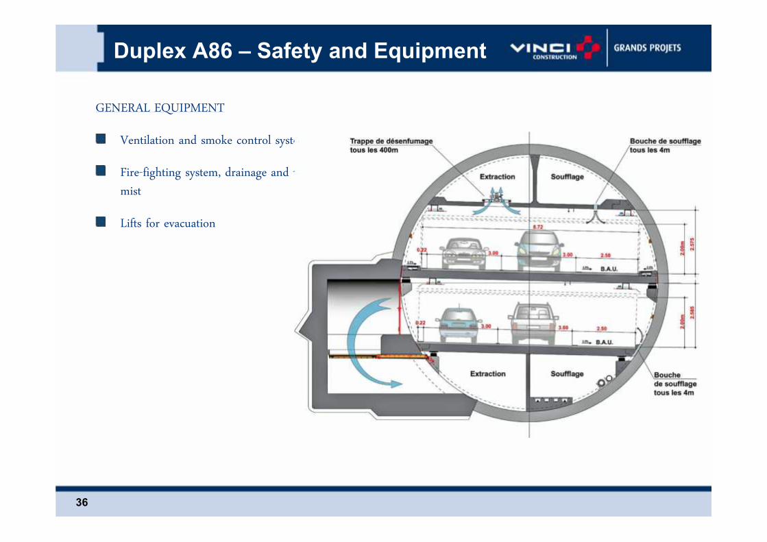
Cross Section
Doubling the link-up’s capacity
Diversification of the interchanges with surfaceroads
Significant reduction of each interchange’ssurface
Reduced impact on the environment
Increased safety
Designed for peaceful driving

13
Cross Section : Clearance and widthClearance:• Inside diameter of the tunnel: 10.40m• Allowed clearance for lightweight vehicles: 2.00 m• Ceiling clearance: 2.55 mLane width:• 2 x 3 m-wide lanes + 2.5 m-wide escape lane• Or 3 x 2.80 m-wide lanes, near interchanges.

14
1-A86 Duplex overview
2- Interchanges
3- Safety Works and Equipment
4- Supervision, Control and Monitoring (SCADA)
5- Operations & Maintenance

15
Rueil-Malmaison Interchange

16
Rueil-Malmaison Interchange View

17
Section 1:Opening day 26 june 2009:
Rueil-Malmaison Interchange Toll

18
Interchange A86/A13

19 19
Interchange A86/A13 : 3D View
Underground Interchange with 3 levels and8 junctions :
3 km secundary tunnels

20
Interchange A86/A13 Aerial Wiew

21
Interchange A86/A13 Toll Aerial Wiew

22
Interchange A86 Pont Colbert

23
Interchange A86 Pont Colbert View

24
Interchange A86 Pont Colbert View

25
1-A86 Duplex overview
2- Interchanges
3- Safety Works and Equipment
4- Supervision, Control and Monitoring (SCADA)
5- Operations & Maintenance

26
Civil Works
Skip underground led to the choice of the methode of digging the tunnel:13 geological horizons and 4 groundwater:Tunnelier dual mode "earth pressure" and “slurry mode“ diameter 11,60 m
SOCATOP - TUNNEL EST
Tunnelier en configuration pression de boue
J upe
V érin d e p oussée
S as p erso nnel
V érin s detéle sco paged e la tête
E recteur
V is de mar inage
Tê ted 'ab attage
M odule d'
d e tê tee ntra în ement
R otule et
d e tê tetéles cope
S upp ort d'e ntra în ement
V érinsa nti cou ple
C orp s d u b ouc lier
S tru ctu re en croixd e ré ac tion et des upp ort
V érin de pousséeSOCATOP - TUNNEL ESTCorps du bouc lier
Têted 'abattage
M odule d'
de tê teentra înement
Rotule et
de tê tetéles cope
S upport d'entra înement
V érinsanticouple
V érins detélescopagede la tête
S as personnel
E recteur
S tructure en croixde réac tion et des upport
V is de mar inage
J upe
Tunnelier en configuration extraction déblais par vis

27
Slabs and pavement
Drive comfort:continuous rolling slabsanchored to the end
Pavement clear coated syntheticwith titanium oxide

28
Safety works
«Two tunnels in one» -One-way traffic
Emergency alcoves and shelters every200 m
Independent ventilation for each level

29
Redundancy of emergency acess ways
Emergency access and exit shafts to the surface, every 1,200 m.Accident level and safe level are connected by recess with escape stairways every 200 m

30
safety works 3D Views
Smoke exhaust niche
Safety recess withEscape stairways

31
Typical excavation sequence after ground treatment or congelation
- Forming openings in lining
- Installation working platform
- Excavation and support (steel ribs and shotcrete)
Recess and shafts construction

32
Recess and shafts construction
congelation with thermal control

33
Recess and shafts construction
Completed safety recess Completed ventilation recess
40 safety recesses (every 200 m)28 ventilation recesses (every 400m).

34
Exit shafts for emergency services
7 Standardemergency shaft20m to 90m high

35
Other Safety works
2 Intermediate Ventilation unitand emergency shaft
36
Duplex A86 – Safety and Equipment
GENERAL EQUIPMENTVentilation and smoke control systemFire-fighting system, drainage and watermistLifts for evacuation

37
Overview of Ventilation System

38
Rueil Malmaison Ventilation Unit

39
Specific Hazard Investigation
Heavy trucks are not allowed in the tunnel :The energy produced by a light car in fire isten times lower then by a heavy truck
A ventilation simulation tool was developedfor the project and was used for the hazardinvestigation
Design fire curvesMain tunnel fire Access road fire (interchanges)

40
Smoke Control System
Powerful smoke extraction system : fire exhaust dampers located every 400m ( 110 to 130 m3/sextraction)Pressurized shelters and shafts to prevent smoke spread from one roadway to the other and assure a safepath of evacuation

41
Smoke Control System
Design criteria:Longitudinal smoke controlSystem designed for maximum tunnel traffic flow:
3,400 vehicles/hour/direction when opening to operation4,400 vehicles/hour/direction long term operation
Emergency pressurization in the escape staircases:2 pressurized staircases upstream the fire place6 pressurized staircases downstream the fire place
V > 2 m/s V > 1 m/s

42
Fire & emergency ventilation site test
Site fire and smoke control test in the Tunnel:
Tests from 2 MW to 15 MW (Eptane)
One test with 3 vehicules 15MW

43
Operations emergency procedures
Traffic control and detection:T0 = fire or incident start timeT0 + 2 minutes: maximum automatic incident/fire detection delay
Traffic management :T0 + 2 minutes: traffic shutdown at the tunnel entrance (toll barrier)T0 + 3 minutes : activation of other traffic management device (barriers into main tunnel, at the access roadsconnexions…)
Emergency Ventilation :Air velocity maintained >1 m/s before fire fine localisation and smoke control activationT0 + 3 minutes: pressurisation of the safe roadway and sheltersT0 + 4 minutes: smoke exhaust activation depending on the predefined scenario
Specific Hazard Investigation

44
Sample Scenario : Espace trafic supérieur
Specific Hazard Investigation
Time-visibility diagram :Test performed for each fire location with different trafic or climate conditions(more than 500 fire scenarios)

45
Emergency Response Plan & Rescue Services intervention
25min
20min
Arrivée du module AgEx enprovenance de l'échangeur
A13
Arrivée du module AgExen provenance de PC
Activation fermeture tunnel
Désenfumage à 100 %Mise en route du scénario de désenfumage
Départ des sapeurs-pompiers
Dernier véhicule quitte l'espace trafic sain à T0+11'Ouverture des ET vers espace trafic sain
Arrivée des premiers sapeurs-pompiers
Arrivée du module AgExen provenance de Rueil
<
Specific Hazard Investigation

46
Fire Fighting System: Fire Hydrant
The fire-fighting system enables safe and instantaneous supply from the fire hydrants locatedevery 200 meters along the traffic ways of the East tunnel and the interchanges.A fire hydrant is installed in each emergency refuge area.

47
In the event of a major fire or a major accident, the Water Mist system must:
Prevent or slow down the fire spread to other vehicles,Confine the fire source (heat release rate and extension in space)Reduce the impact of the fire (temperature, toxicity….) on people during evacuationImprove the conditions for the emergency services to intervene.
Fire Fighting Water Mist System
Tests in the Tunnel Preliminary Tests with car fire

48
1-A86 Duplex overview
2- Interchanges
3- Safety Works and Equipment
4- Supervision, Control and Monitoring (SCADA)
5- Operations & Maintenance
49
Duplex A86 – SCADA
SUPERVISION & CENTRAL CONTROL CENTREThe Supervision and Central Control System gives the operator themeans of efficiently operating the tunnel by:
Traffic managementCentralised technical management
For this purpose, the SCADA system performs the following tasks:Inform the operator (real-time)Control and manage the technical deviceManage the alarms, providing traceability and records
The SCADA has additional tasks :Computer-aided assistance to the operator in making a decisionTraffic events forecast

50
Supervision & Central Control Center
Ergonomy of the Control Center
Constant and real-time monitoring oftraffic events and equipments status

51
Traffic Management
No congestion allowed inside the tunnel, achieved by trafficcontrol on entrances and exits, and within the tunnelAutomatic Incident DetectionVariable Message SignsCustomer Assistance PatrolFM radio broadcast override
52
Electrical Equipment (EPC-E&M)
Ventilation and smoke control (EPC-CW)65 axial ventilators56 jetfans4 twin air curtains (18 accelerators each)56 variable speed drives310 motorised fire dampers
Fire-fighting, drainage and water mist systems (EPC-CW)9 pumps11 drainage pumps135 fire hydrants and manifolds17500 sprinkler nozzles
Lifts and technical room ancillary device (EPC-CW)7 lifts in the emergency shafts, 6 lifts in the ventilation unitsTechnical rooms ventilation, air conditioning and firedetection systems

53
Electrical Equipment (EPC-E&M)
Traffic Signs62 variable messages signs340 signs for lane allocation16 access controls9 systems to detect oversized vehicles
CCTV400 cameras
Emergency telephone system120 emergency telephone units700 emergency call pushbuttons
Traffic management50 traffic data collecting stations (counting, speed)Automated system for detecting bottlenecks on each exitslip road

54
Electrical Equipment (EPC-E&M)
Power Distribution10MW installed power4 x 2,000 KVA emergency power generators80 km of 20KV HV cables400 km of 400V LV distribution cables
Inside/Outside lighting units10,000 lighting units in tunnel and covered slip roads350 outside lighting units
Fire Detection

55
Electrical Equipment (EPC-E&M)
Telephone, intercom
Transmission systemCounter rotary twin fibre optic ring, SDH 155 Mbits
Access control of vehicles and staff
Supervision and central control system150,000 control points16 canton automated units75 offset entry/exit racks
56
Electrical Equipment (EPC-E&M)
Automated detection of stopped vehicles160 video analysers
Radio-communications25 km of broadcast cable
Speed control36 control radars
Toll8 tollbooths at Rueil-Malmaison9 tollbooths at Vaucresson / A138 tollbooths at Versailles / Pont Colbert

57
1-A86 Duplex overview
2- Interchanges
3- Safety Works and Equipment
4- Supervision, Control and Monitoring (SCADA)
5- Operations & Maintenance
58
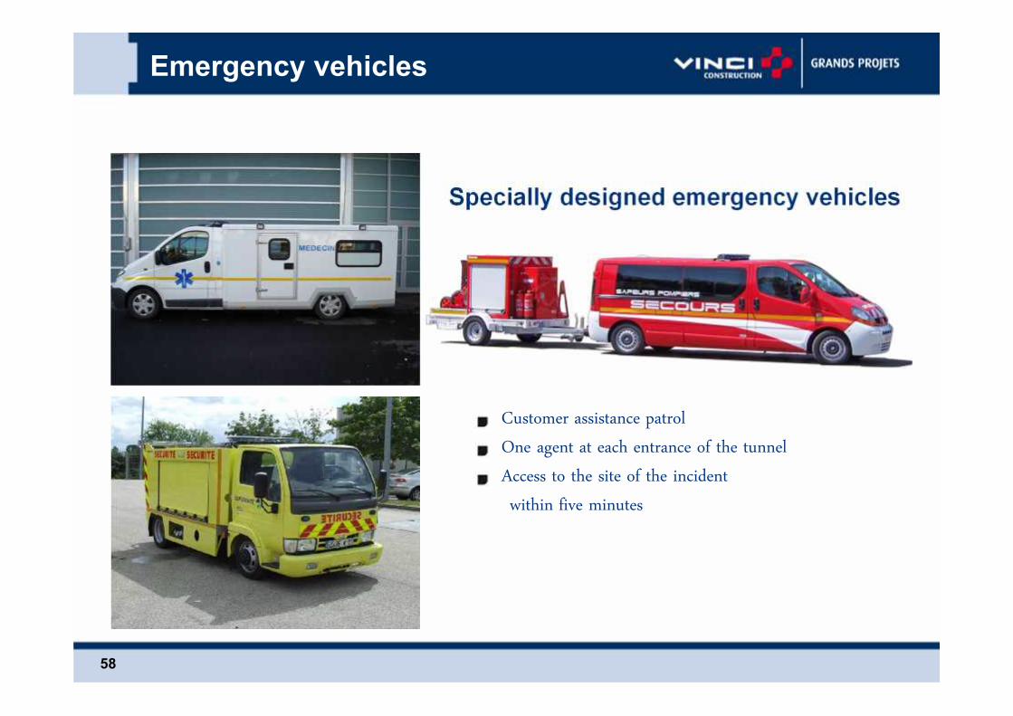
Customer assistance patrolOne agent at each entrance of the tunnelAccess to the site of the incidentwithin five minutes
Specially designed emergency vehicles
Emergency vehicles

Operations and Maintenance
Traffic Average traffic: between 25 000 and 30 000 vehicles per day Between 40 and 45% of electronic toll transactions Rise of the second section faster than the first section
Breakdowns, accidents and fires 1 breakdown every 2 days 1 accident all equipment 2 to 3 months 2 departures on fire since the opening of the tunnel
Events: mainly oversize
Staff100 employees, including 75 agents operating: 65 agents viability and security and supervisors 10 receivers and maintenance technicians
59

60
EndThanks for your attention