tubing and pipe.pdf
TRANSCRIPT


KSection K
tubing and pipe
The various tubular products have been arranged in this sec-tion according to the primary end uses for which they are manufactured:
MecHAnicAL tubing
Commercial and Aircraft Quality.
pipe —— Steel and Aluminum
StRuctuRAL SteeL tubing
Square and Rectangular
AiRcRAFt SteeL tubing
HYDRAuLic Line tubing
Refer to the index tabs following this page to locate infor-mation regarding the various classes of tubular prod-ucts, including sizes, weights, and technical data.
This arrangement is presented to make it easy for you to deter-mine the availability of tubing or pipe for a particular specifica-tion. However, it is often possible to substitute an item in one class for a similar item in another class when the latter is not available. For example, pipe and structural tubing may often be inter-changed, or a hydraulic tube may be used for a mechanical application. For critical applications, though, especially when governed by the specifications, care should be taken to insure that the tube ordered possesses the necessary properties.
Sec. K page 1
pages 3-96
Mechanical &Structural
tubing
pages 129-135
titaniumtubing
pages 97-107
pipe
pages 107-112
Structuraltubing
pages 113-116
AircraftAirframe
tubing
pages 117-128
HydraulicLine
tubing

Sizes listed herein are those normally available from stock at the time of publication.
However, our stocks are continually being adjusted to reflect changing demands.
The item you need may have been added to stock after this book went to press.
If the particular item you need cannot be supplied from stock immediately, we will
endeavor to obtain it for you, either locally or from another part of the country. With
our special knowledge of tubing sources and numerous contacts in the industry,
we are in a good position to locate the hard-to-get items you need. Use this EMJ
service and your time will be free for other things.
Also, as agents of all leading tubing mills, we can expedite production and delivery
of material direct from the mill. This includes not only special sizes, but also special
analyses and grades such as the following:
12 chrome Series Alloy 718
A 286 Alloy 400
n 155 Alloy K-500
19-9 DL Alloy 600
19-9 DX Alloy X-750
17-4 Leaded Steels
17-7 Resulphurized Steels
Alloy 20cb-3
We invite your inquiries regarding all your tubing needs.
Sec. K page 2

Sec. K page 3
RounD SteeL AnD ALuMinuM
MecHAnicAL AnD StRuctuRAL tubing
Mechanical tubing is used for a wide variety of mechanical purposes as opposed to structural and pressure applications. It is generally produced to meet specific end use requirements which may be static or dynamic in nature.
It is available in a wide range of sizes, shapes, analyses, and mechanical proper-ties. Compared with pipe, it is produced to closer tolerances and better finishes.
SiZeS AnD WeigHtS oF MecHAnicAL AnD StRuctuRAL tubing carbon, Alloy, and Stainless Steels; Aluminum Round . . . . . . . . . . . . . . . . . . . . . . . . . . . . . . . . . . . . . . . . . . . . . . . . . . . . . 4-64
DeScRiption oF inDiViDuAL gRADeS carbon Steel: Seamless . . . . . . . . . . . . . . . . . . . . . . . . . . . . . . . . . . . . . . . . . . . . . . . . . 65-70 Drawn Over Mandrel . . . . . . . . . . . . . . . . . . . . . . . . . . . . . . . . . . . . . . . . 71-74 Drawn Over Mandrel, Special Smooth ID (for Hydraulic Cylinders) . . . . . . . 75 Cold Drawn Butt Welded . . . . . . . . . . . . . . . . . . . . . . . . . . . . . . . . . . . . . . . . 76 Electric —— Resistance Welded . . . . . . . . . . . . . . . . . . . . . . . . . . . . . . . 77-79 Aircraft Alloy Steel . . . . . . . . . . . . . . . . . . . . . . . . . . . . . . . . . . . . . . . . . . 80-81 commercial Alloy Steel . . . . . . . . . . . . . . . . . . . . . . . . . . . . . . . . . . . . . . 82-83 Stainless Steel . . . . . . . . . . . . . . . . . . . . . . . . . . . . . . . . . . . . . . . . . . . . . 84-89 Aluminum . . . . . . . . . . . . . . . . . . . . . . . . . . . . . . . . . . . . . . . . . . . . . . . . . 90-96
KeY to AbbReViAtionS AnD SYMboLSuSeD on tHe FoLLoWing pAgeS
Four-digit numbers (e.g., 1018, 4130) represent analysis designations of carbon and alloy seamless tubing. All such items are Cold Drawn except when prefixed HF.
three-digit numbers (e.g., 304, 321) represent analysis designations of stainless steels. Stainless tubes are seamless except where the designation includes WD, in which case they are welded and drawn.
Four-digit number followed by temper designations (e.g., 3003-O, 2024-T3) rep-resent alloy and temper of aluminum.
cDbW —— Cold Drawn Butt Welded cReW —— Cold Rolled Electric Welded HReW —— Hot Rolled Electric Welded HF —— Hot Finished Ht —— Heat Treated Hb —— Hollow Bar SSiD —— Drawn Over Mandrel, Special Smooth ID StRuct —— Structural WD —— Welded and Drawn, Stainless DoM —— Drawn Over Mandrel, 520/1020/1026
note RegARDing WeigHtS
All weights shown herein are theoretical, and actual weight may vary according to tolerances and chemical composition. Therefore, weights should be used for estimating purposes only.

RounD MecHAnicAL tubingSee Page 3 of this section for index to descriptions
and key to abbreviations. Outside Wall Thickness Inside Wt. per Foot Diameter BWG or Decimal Diameter carbon Alloy Stainless Alum- (Inches) Fraction Inches (Inches) Steel Alum. Steel Steel Steel inum 1/32 36 .004 .023 .0012 .0004 321 —— .006 .020 .0016 .0006 321 347 34 .007 .017 .0018 .0006 347 33 .008 .015 .0020 .0007 321 31 .010 .011 .0023 .0008 304 321 1/16 —— .006 .051 .0036 .0013 321 33 .008 .047 .0047 .0017 304 321 31 .010 .043 .0057 .0020 304 316 321 347 30 .012 .038 .0065 .0023 304 321 28 .014 .035 .0073 .0026 304 321 27 .016 .031 .0080 .0028 304 316 321 26 .018 .027 .0087 .0031 321 25 .020 .023 .0092 .0032 304 316 321 24 .022 .019 .0096 .0034 321 22 .028 .006 .0105 .0037 304 316 .065 22 .028 .008 .0111 .0039 304 .083 31 .010 .063 .0078 .0027 321 1/8 —— .006 .113 .0076 .0026 321 31 .010 .105 .0123 .0043 347 30 .012 .101 .0145 .0051 304 27 .016 .093 .0186 .0065 304 316 25 .020 .085 .0224 .0078 304 6061-T6 304WD 316 321 24 .022 .081 .0242 .0085 1018/1026 22 .028 .069 .0290 .0101 1018/1026 304 3003-O 304WD 316 321 21 .032 .061 .0318 .0112 1018/1026 321 20 .035 .055 .0336 .0115 1018/1026 4130 304 5052-O 304WD 316 18 .049 .027 .0398 .0140 1018/1026 304 316
Sec. K page 4

RounD MecHAnicAL tubingSee Page 3 of this section for index to descriptions
and key to abbreviations. Outside Wall Thickness Inside Wt. per Foot Diameter BWG or Decimal Diameter carbon Alloy Stainless Alum- (Inches) Fraction Inches (Inches) Steel Alum. Steel Steel Steel inum
5/32 27 .016 .124 .0240 .0084 304 321 22 .028 .100 .0384 .0135 1018/1026 304 20 .035 .086 .0452 .0159 1018/1026 18 .049 .058 .0560 .0197 1018/1026 3/16 27 .016 .156 .0294 .0103 304 304WD 26 .018 .152 .0327 .0115 1018/1026 25 .020 .148 .0359 .0126 304 316WD 24 .022 .144 .0390 .0138 1018/1026 2024-T3 3003-H14 23 .025 .138 .0433 .0150 6061-T6 22 .028 .131 .0478 .0168 1018/1026 4130 304 2024-T3 304WD 3003-O 316 5052-O 6061-T6 21 .032 .124 .0533 .0188 1018/1026 2024-T3 20 .035 .118 .0572 .0201 1018/1026 4130 304 2024-T3 316 3003-H14 5052-O 6061-T6 19 .042 .104 .0655 .0230 1018/1026 18 .049 .090 .0727 .0256 1018/1026 4130 304 2024-T3 316 6061-T6 17 .058 .072 .0805 .0283 1018/1026 16 .065 .058 .0854 .0300 1018/1026 4130 304 14 .083 .022 .0929 .0326 1018/1026 7/32 27 .016 .187 .0346 .0122 304WD 25 .020 .179 .0425 .0149 304WD 321 20 .035 .149 .0688 .0242 1018/1026 18 .049 .121 .0888 .0312 1018/1026 1/4 —— .006 .238 .0156 .0055 304 31 .010 .230 .0256 .0090 347 27 .016 .218 .0400 .0140 6061-T6 25 .020 .210 .0491 .0173 304 2024-T3 304WD 5052-O 316 6061-O 6061-T6 24 .022 .206 .0536 .0189 1018/1026 3003-H14 5052-O 23 .025 .200 .0598 .0210 1018/1026 22 .028 .194 .0664 .0235 1018/1026 4130 304 2024-T3 DOM 304WD 3003-H14 316 3003-O 5052-O 6061-T4 6061-T6 21 .032 .186 .0745 .0263 1018/1026 2024-T3 DOM
Sec. K page 5

RounD MecHAnicAL tubingSee Page 3 of this section for index to descriptions
and key to abbreviations. Outside Wall Thickness Inside Wt. per Foot Diameter BWG or Decimal Diameter carbon Alloy Stainless Alum- (Inches) Fraction Inches (Inches) Steel Alum. Steel Steel Steel inum 1/4 20 .035 .180 .0804 .0281 1018/1026 4130 304 2024-T3 (Cont.) DOM 304WD 3003-H14 316 3003-O 316WD 5052-O 321 6061-T4 6061-T6 19 .042 .166 .0933 .0328 1018/1026 18 .049 .152 .1052 .0371 1018/1026 4130 304 2024-T3 DOM 304WD 5052-O 316 6061-T6 316WD 17 .058 .134 .1189 .0419 1018/1026 4130 2024-T3 DOM 6061-T6 —— .060 .130 .1218 .0429 2024-T3 16 .065 .120 .1284 .0453 1018/1026 4130 304 2024-T3 DOM 304WD 6061-T6 316 347 15 .072 .106 .1369 .0481 1018/1026 4130 14 .083 .084 .1480 .0523 1018/1026 304 2024-T3 DOM 316 13 .095 .060 .1573 .0552 1018/1026 304 316 12 .109 .032 .1641 .0576 1018/1026 9/32 18 .049 .183 .1214 .0426 1018/1026 5/16 25 .020 .273 .0626 .0214 304 3003-H14 304WD 5052-O 316 6061-T4 24 .022 .268 .0684 .0240 1018/1026 23 .025 .263 .0769 .0270 1018/1026 4130 22 .028 .257 .0852 .0300 1018/1026 4130 304WD 3003-H14 DOM 316WD 5052-O 321WD 6061-O 347 6061-T4 6061-T6 21 .032 .249 .0960 .0337 1018/1026 DOM 20 .035 .243 .1039 .0366 1018/1026 4130 304 2024-O DOM 304WD 2024-T3 316 3003-H14 347 3003-O 5052-O 6061-O 6061-T6 19 .042 .229 .1216 .0427 1018/1026 18 .049 .215 .1382 .0487 1018/1026 4130 304WD 2024-T3 DOM 316 5052-O 6061-T6 17 .058 .192 .1580 .0561 1018/1026 4130 2024-T3 DOM 6061-T6
Sec. K page 6

RounD MecHAnicAL tubingSee Page 3 of this section for index to descriptions
and key to abbreviations. Outside Wall Thickness Inside Wt. per Foot Diameter BWG or Decimal Diameter carbon Alloy Stainless Alum- (Inches) Fraction Inches (Inches) Steel Alum. Steel Steel Steel inum 5/16 1/6 .063 .188 .1677 .0583 6061-T6 (Cont.) 16 .065 .182 .1722 .0594 1018/1026 4130 304 DOM 304WD 316 —— .075 .163 .1906 .0674 4130 2024-T3 14 .083 .147 .2039 .0716 1018/1026 4130 13 .095 .122 .2212 .0777 1018/1026 4130 12 .109 .095 .2375 .0834 1018/1026 11 .120 .073 .2473 .0869 1018/1026 .322 —— .070 .182 .2242 .0787 4130HT 11/32 21 .032 .280 .1066 .0374 1018/1026 18 .049 .246 .1544 .0542 1018/1026 3/8 31 .010 .355 .0390 .0137 304 347 25 .020 .335 .0758 .0267 304WD 5052-O 347WD 6061-T6 24 .022 .331 .0829 .0292 1018/1026 3003-H14 DOM 5052-O 23 .025 .325 .0935 .0328 1018/1026 304WD 22 .028 .319 .1038 .0366 1018/1026 4130 304 2024-T3 DOM 304WD 3003-H14 316 5052-O 316WD 6061-T4 321WD 6061-T6 21 .032 .311 .1172 .0413 1018/1026 316 3003-H14 DOM 20 .035 .305 .1271 .0449 1018/1026 4130 304 2024-O DOM 304WD 2024-T3 CREW 316 3003-H14 316WD 3003-O 321 5052-O 6061-O 6061-T4 6061-T6 19 .042 .293 .1494 .0525 DOM 4130 18 .049 .277 .1706 .0602 1018/1026 4130 304 2024-T3 DOM 304WD 5052-O CREW 316 6061-T6 STRUCT 316WD 17 .058 .259 .1964 .0694 1018/1026 4130 304 2024-T3 DOM 6061-T6 16 .065 .245 .2152 .0755 1018/1026 4130 304 2024-T3 DOM 304WD 6061-T6 CDBW 316 STRUCT 316WD 347 15 .072 .231 .2330 .0818 1018/1026 14 .083 .209 .2588 .0918 1018/1026 4130 316 2024-T3 DOM 6061-T6 —— .090 .195 .2739 .0968 4130 2024-T3 13 .095 .185 .2841 .0998 1018/1026 4130 304 DOM 316
Sec. K page 7

RounD MecHAnicAL tubingSee Page 3 of this section for index to descriptions
and key to abbreviations. Outside Wall Thickness Inside Wt. per Foot Diameter BWG or Decimal Diameter carbon Alloy Stainless Alum- (Inches) Fraction Inches (Inches) Steel Alum. Steel Steel Steel inum 3/8 12 .109 .157 .3097 .1088 1018/1026 304 6061-T6 (Cont.) 11 .120 .135 .3268 .1148 1018/1026 4130 304 316 321 10 .134 .107 .3449 .1211 1018/1026 304 13/32 20 .035 .336 .1389 .0488 1018/1026 18 .049 .308 .1868 .0656 1018/1026 16 .065 .276 .2367 .0831 1018/1026 14 .083 .240 .2863 .1005 1018/1026 13 .095 .216 .3155 .1108 1018/1026 11 .120 .166 .3665 .1287 1018/1026 .378 1/16 .062 .254 .2092 .0735 4130 .385 15 .072 .242 .2407 .0854 4130 —— .100 .185 .3044 .1069 4130HT 7/16 33 .008 .421 .0367 .0129 321 25 .020 .398 .0893 .0314 304WD 24 .022 .393 .0977 .0343 1018/1026 23 .025 .388 .1103 .0387 1018/1026 304WD 22 .028 .381 .1126 .0431 1018/1026 4130 304WD 6061-T6 DOM 21 .032 .374 .1388 .0487 1018/1026 DOM 20 .035 .367 .1506 .0530 1018/1026 4130 304WD 2024-T3 DOM 316 3003-O 347 5052-O 6061-T6 19 .042 .354 .1776 .0624 1018/1026 4130 18 .049 .340 .2036 .0714 1018/1026 4130 304 2024-T3 DOM 304WD 6061-T6 316 17 .058 .322 .2354 .0826 1018/1026 4130 2024-T3 DOM 16 .065 .307 .2589 .0908 1018/1026 4130 304 2024-T3 DOM 304WD 6061-T6 316 15 .072 .294 .2814 .0988 4130 14 .083 .272 .3147 .1110 1018/1026 4130 304 2024-T3 DOM —— .088 .263 .3289 .1155 4130 —— .090 .258 .3345 .1178 2024-T3 13 .095 .247 .3480 .1224 1018/1026 4130 304 2024-T3 DOM 321 12 .109 .220 .3830 .1345 1018/1026 11 .120 .197 .4075 .1431 1018/1026 4130 321 6061-T6 —— .129 .180 .4257 .1495 4130HT 10 .134 .169 .4351 .1528 1018/1026 4130 5/32 .156 .125 .4698 .1650 1018/1026 .448 15 .072 .304 .2891 .1015 4130HT —— .102 .245 .3769 .1324 4130HT
Sec. K page 8

RounD MecHAnicAL tubingSee Page 3 of this section for index to descriptions
and key to abbreviations. Outside Wall Thickness Inside Wt. per Foot Diameter BWG or Decimal Diameter carbon Alloy Stainless Alum- (Inches) Fraction Inches (Inches) Steel Alum. Steel Steel Steel inum 1/2 25 .020 .460 .1025 .0356 3003-H14 6061-O 24 .022 .456 .1123 .0394 1018/1026 3003-H14 5052-O 6061-T6 22 .028 .444 .1411 .0496 1018/1026 4130 304 2024-T3 DOM 304WD 3003-H14 316 5052-O 321 6061-T4 347 6061-T6 21 .032 .436 .1599 .0562 1018/1026 DOM 20 .035 .430 .1738 .0612 1018/1026 4130 304 2024-T3 DOM 304WD 3003-H14 CREW 316 3003-O 316WD 5052-O 6061-O 6061-T4 6061-T6 19 .042 .416 .2054 .0721 1018/1026 321WD 5052-O 6061-T4 18 .049 .402 .2360 .0829 1018/1026 4130 304 2024-T3 DOM 304WD 3003-O CREW 316WD 5052-O HREW 6061-O 6061-T4 6061-T6 17 .058 .384 .2738 .0962 1018/1026 4130 2024-T3 DOM 6061-O 6061-T6 16 .065 .370 .3020 .1061 1018/1026 4130 304 2024-T3 DOM 304WD 3003-H14 CREW 316 5052-O HREW 316WD 6061-T6 15 .072 .356 .3291 .1156 1018/1026 4130 347 14 .083 .334 .3696 .1298 1018/1026 4130 304 2024-T3 DOM 316 6061-T6 13 .095 .310 .4109 .1443 1018/1026 4130 304 2024-T3 DOM 316 6061-T6 347WD 12 .109 .282 .4552 .1599 1018/1026 4130 304 11 .120 .260 .4870 .1710 1018/1026 4130 304 6061-T6 DOM 316 —— .131 .238 .5163 .1813 4130HT 10 .134 .232 .5238 .1840 1018/1026 4130 304 5/32 .156 .187 .5731 .2013 1018/1026 4130 321 3/16 .188 .125 .6264 .2200 1018/1026 4130
17/32 16 .065 .401 .3237 .1137 1018/1026
14 .083 .365 .3971 .1395 1018/1026
13 .095 .341 .4424 .1554 1018/1026
11 .120 .291 .5267 .1850 1018/1026
Sec. K page 9

RounD MecHAnicAL tubingSee Page 3 of this section for index to descriptions
and key to abbreviations. Outside Wall Thickness Inside Wt. per Foot Diameter BWG or Decimal Diameter carbon Alloy Stainless Alum- (Inches) Fraction Inches (Inches) Steel Alum. Steel Steel Steel inum
9/16 24 .022 .519 .1271 .0446 1018/1026
23 .025 .512 .1436 .0504 1018/1026
22 .028 .506 .1600 .0562 1018/1026 304 304WD
21 .032 .499 .1815 .0637 1018/1026
20 .035 .492 .1974 .0696 1018/1026 4130 304 2024-T3 DOM 304WD 316
19 .042 .479 .2337 .0821 1018/1026 321 18 .049 .464 .2690 .0948 1018/1026 4130 304WD 2024-T3 DOM 316
17 .058 .447 .3128 .1099 1018/1026 321
16 .065 .432 .3457 .1218 1018/1026 4130 304WD 2024-T3 DOM 316
14 .083 .396 .4255 .1494 1018/1026 4130 321 DOM
13 .095 .372 .4748 .1667 1018/1026 4130 304 DOM
12 .109 .344 .5285 .1856 1018/1026 4130
11 .120 .322 .5677 .1994 1018/1026 4130 304 321
1/8 .125 .313 .5847 .2060 1018/1026 304 2024-T3 DOM 321
10 .134 .295 .6140 .2156 1018/1026 4130HT
5/32 .156 .250 .6781 .2381 1018/1026 4130 321
3/16 .188 .188 .7529 .2644 1018/1026 304 321
7/32 .219 .125 .8046 .2826 4130
.572 —— .071 .429 .3799 .1334 4130HT
—— .101 .370 .5081 .1784 4130HT
Sec. K page 10

RounD MecHAnicAL tubingSee Page 3 of this section for index to descriptions
and key to abbreviations. Outside Wall Thickness Inside Wt. per Foot Diameter BWG or Decimal Diameter carbon Alloy Stainless Alum- (Inches) Fraction Inches (Inches) Steel Alum. Steel Steel Steel inum 5/8 31 .010 .605 .0657 .0231 304WD
27 .016 .593 .1041 .0366 5052-O
24 .022 .581 .1417 .0498 1018/1026 3003-H14
23 .025 .575 .1602 .0563 1018/1026 22 .028 .569 .1785 .0627 1018/1026 4130 316WD 2024-T3 DOM 3003-H14 5052-O 6061-T6 21 .032 .561 .2027 .0712 1018/1026 20 .035 .555 .2205 .0775 1018/1026 4130 304 2024-T3 DOM 304WD 3003-H14 CREW 316 5052-O 6061-O 6061-T4 6061-T6 19 .042 .541 .2615 .0918 1018/1026 5052-O 18 .049 .527 .3014 .1060 1018/1026 4130 304 2024-T3 DOM 4340 304WD 3003-H14 CREW 316 5052-O HREW 316WD 6061-T4 6061-T6 17 .058 .509 .3512 .1234 1018/1026 4130 2024-T3 DOM 5052-O 6061-T6 16 .065 .495 .3888 .1367 1018/1026 4130 304 2024-T3 DOM 304WD 3003-H14 CREW 316 3003-O 316WD 5052-O 321 6061-T6 15 .072 .471 .4252 .1493 1018/1026 14 .083 .459 .4805 .1693 1018/1026 4130 304 2024-T3 DOM 316 6061-T6 HREW 13 .095 .435 .5377 .1888 1018/1026 4130 304 6061-T6 DOM 304WD 12 .109 .407 .6007 .2110 1018/1026 DOM 11 .120 .385 .6472 .2273 1018/1026 4130 304 DOM 316 1/8 .125 .375 .6675 .2344 DOM 4130 2024-T3 6061-T6 10 .134 .357 .7027 .2468 1018/1026 304 DOM 5/32 .156 .312 .7814 .2744 1018/1026 4130 DOM 3/16 .188 .250 .8774 .3081 1018/1026 4130 304 DOM 316 321 7/32 .219 .187 .9496 .3335 1018/1026 321 DOM 1/4 .250 .125 1.001 .3516 1018/1026
Sec. K page 11

RounD MecHAnicAL tubingSee Page 3 of this section for index to descriptions
and key to abbreviations. Outside Wall Thickness Inside Wt. per Foot Diameter BWG or Decimal Diameter carbon Alloy Stainless Alum- (Inches) Fraction Inches (Inches) Steel Alum. Steel Steel Steel inum
.635 15 .072 .492 .4329 .1520 4130HT
11/16 25 .020 .648 .1427 .0501 304WD 22 .028 .631 .1974 .0693 1018/1026 304WD 321
20 .035 .617 .2441 .0857 1018/1026 304 304WD
18 .049 .589 .3344 .1174 1018/1026 304WD DOM
17 .058 .571 .3902 .1370 1018/1026
16 .065 .557 .4325 .1519 1018/1026 4130 304WD DOM
14 .083 .522 .5363 .1883 1018/1026 304 DOM
13 .095 .497 .6017 .2113 1018/1026 321 DOM
12 .109 .469 .6740 .2367 1018/1026
11 .120 .448 .7279 .2556 1018/1026 4130 304 321
1/8 .125 .438 .7508 .2594 1018/1026
10 .134 .419 .7928 .2784 1018/1026
5/32 .156 .375 .8864 .3113 1018/1026 4130
3/16 .188 .312 1.004 .3526 1018/1026 4130 321
7/32 .219 .250 1.097 .3853 1018/1026
3/4 27 .016 .718 .1254 .0440 3003-H14
25 .020 .710 .1559 .0548 5052-O 6061-O 6061-T6
24 .022 .706 .1711 .0601 1018/1026 3003-H14
23 .025 .700 .1936 .0680 1018/1026
22 .028 .694 .2159 .0758 1018/1026 4130 304 2024-T3 DOM 304WD 3003-H14 5052-O 6061-T6
21 .032 .686 .2425 .0862 1018/1026
Sec. K page 12

RounD MecHAnicAL tubingSee Page 3 of this section for index to descriptions
and key to abbreviations. Outside Wall Thickness Inside Wt. per Foot Diameter BWG or Decimal Diameter carbon Alloy Stainless Alum- (Inches) Fraction Inches (Inches) Steel Alum. Steel Steel Steel inum 3/4 20 .035 .680 .2673 .0938 1018/1026 4130 304 2024-T3 (cont.) DOM 304WD 3003-H14 CREW 316 3003-O 316WD 5052-O 6061-O 6061-T4 6061-T6 19 .042 .666 .3176 .1115 1018/1026 4130 18 .049 .652 .3668 .1288 1018/1026 4130 304 2024-T3 DOM 304WD 3003-H14 CREW 316 3003-O 316WD 5052-O 321 6061-O 321WD 6061-T4 347WD 6061-T6 17 .058 .643 .4287 .1506 1018/1026 4130 2024-T3 DOM 3003-H14 6061-O 6061-T6 1/16 .062 .626 .4556 .1600 CREW 3003-O 16 .065 .620 .4755 .1670 1018/1026 4130 304 2024-T3 DOM 304WD 3003-H14 CREW 316 3003-O HREW 316WD 5052-O 347 6061-O 6061-T6
14 .083 .584 .5913 .2077 1018/1026 4130 304 2024-T3 DOM 316 3003-H14 HREW 316WD 6061-T6 13 .095 .560 .6646 .2334 1018/1026 4130 304 2024-T3 DOM 316 6061-T6 HREW
12 .109 .532 .7462 .2621 1018/1026 347 DOM
11 .120 .510 .8074 .2846 1018/1026 4130 304 2024-T3 DOM 316 HREW 347 CDBW
1/8 .125 .500 .8344 .2930 DOM 321 6061-T6
10 .134 .482 .8816 .3096 1018/1026 4130 304 DOM
5/32 .156 .437 .9897 .3476 1018/1026 4130 304 DOM 321 CDBW
3/16 .188 .375 1.128 .3962 1018/1026 4130 304 DOM 316 CDBW 321
7/32 .219 .313 1.242 .4362 1018/1026 4130 DOM
1/4 .250 .250 1.335 .4689 1018/1026 4130 321
Sec. K page 13

RounD MecHAnicAL tubingSee Page 3 of this section for index to descriptions
and key to abbreviations. Outside Wall Thickness Inside Wt. per Foot Diameter BWG or Decimal Diameter carbon Alloy Stainless Alum- (Inches) Fraction Inches (Inches) Steel Alum. Steel Steel Steel inum
13/16 22 .028 .757 .2347 .0824 1018/1026 21 .032 .749 .2669 .0937 1018/1026 20 .035 .742 .2908 .1021 1018/1026 18 .049 .714 .3998 .1404 1018/1026 304 DOM 17 .058 .697 .4677 .1643 1018/1026 16 .065 .682 .5193 .1824 1018/1026 4130 DOM 14 .083 .647 .6471 .2273 1018/1026 4130 13 .095 .622 .7285 .2558 1018/1026 4130 DOM 12 .109 .594 .8195 .2878 1018/1026 4130 DOM 11 .120 .572 .8881 .3120 1018/1026 4130 DOM 10 .134 .544 .9717 .3413 1018/1026 DOM 5/32 .156 .500 1.095 .3846 1018/1026 DOM 3/16 .188 .437 1.255 .4408 1018/1026 DOM 7/32 .219 .375 1.389 .4878 1018/1026 DOM 1/4 .250 .312 1.503 .5279 1018/1026 7/8 24 .022 .831 .2004 .0704 1018/1026
22 .028 .819 .2533 .0890 1018/1026 4130 5052-O DOM
21 .032 .811 .2881 .1012 1018/1026 6061-T6
20 .035 .805 .3140 .1112 1018/1026 4130 304 2024-T3 DOM 304WD 3003-H14 CREW 316 5052-O 6061-T4 6061-T6
19 .042 .791 .3737 .1312 1018/1026
18 .049 .777 .4323 .1530 1018/1026 4130 304 2024-T3 DOM 4130HT 316 3003-H14 CREW 5052-O 6061-T4
17 .058 .759 .5061 .1777 1018/1026 4130 2024-T3 3003-H14 6061-O 6061T6
16 .065 .745 .5623 .1979 1018/1026 4130 304 2024-T3 DOM 304WD 3003-H14 CREW 316 3003-O HREW 321WD 6061-T6
15 .072 .731 .6175 .2169 1018/1026
Sec. K page 14

RounD MecHAnicAL tubingSee Page 3 of this section for index to descriptions
and key to abbreviations. Outside Wall Thickness Inside Wt. per Foot Diameter BWG or Decimal Diameter carbon Alloy Stainless Alum- (Inches) Fraction Inches (Inches) Steel Alum. Steel Steel Steel inum 7/8 14 .083 .709 .7021 .2466 1018/1026 4130 304 (cont.) DOM 316 CREW HREW 13 .095 .685 .7914 .2795 1018/1026 4130 304 2024-T3 DOM 316 6061-T6 CDBW 12 .109 .657 .8917 .3132 1018/1026 304 DOM 11 .120 .635 .9676 .3398 1018/1026 4130 304 DOM 316 HREW 321 1/8 .125 .625 1.001 .3516 1018/1026 DOM CDBW 10 .134 .607 1.060 .3723 1018/1026 DOM 5/32 .156 .562 1.198 .4207 1018/1026 4130 DOM CDBW 3/16 .188 .500 1.379 .4843 1018/1026 4130 304 DOM 316 321 7/32 .219 .437 1.534 .5387 1018/1026 4130 1/4 .250 .375 1.669 .5862 1018/1026 4130 9/32 .281 .313 1.783 .6262 1018/1026 5/16 .313 .250 1.879 .6599 1018/1026 15/16 22 .028 .881 .2721 .0956 1018/1026 21 .032 .874 .3096 .1087 1018/1026 20 .035 .867 .3375 .1185 1018/1026 DOM 19 .042 .541 .2615 .0918 1018/1026 5052-O 18 .049 .839 .4652 .1634 1018/1026 321
17 .058 .822 .5451 .1914 1018/1026
16 .065 .807 .6060 .2128 1018/1026 DOM
14 .083 .772 .7579 .2662 1018/1026
13 .095 .748 .8553 .3004 1018/1026
12 .109 .719 .9651 .3389 1018/1026
11 .120 .697 1.048 .3681 1018/1026 4130
10 .134 .669 1.151 .4042 1018/1026
5/32 .156 .625 1.303 .4576 1018/1026 DOM
3/16 .188 .562 1.506 .5289 1018/1026
7/32 .219 .500 1.682 .5907 1018/1026 4130
5/16 .313 .313 2.089 .7337 1018/1026
Sec. K page 15

RounD MecHAnicAL tubingSee Page 3 of this section for index to descriptions
and key to abbreviations. Outside Wall Thickness Inside Wt. per Foot Diameter BWG or Decimal Diameter carbon Alloy Stainless Alum- (Inches) Fraction Inches (Inches) Steel Alum. Steel Steel Steel inum
.953 —— .114 .725 1.021 .3586 4130HT 1 27 .016 .968 .1681 .0590 6061-O 6061-T4 25 .020 .960 .2093 .0735 6061-O 6061-T6 24 .022 .956 .2298 .0807 1018/1026 5052-O 6061-T4 23 .025 .950 .2603 .0914 1018/1026 6061-T6 22 .028 .944 .2907 .1021 1018/1026 4130 3003-H14 5052-O 6061-T4 21 .032 .936 .3308 .1162 1018/1026 20 .035 .930 .3607 .1275 1018/1026 4130 304 2024-T3 DOM 304WD 3003-H14 CREW 316 5052-O 316WD 6061-T4 6061-T6 19 .042 .916 .4297 .1509 6061-T4 6061-T6 18 .049 .902 .4977 .1754 1018/1026 4130 304 2024-T3 DOM 304WD 3003-H14 CREW 316 3003-O 5052-O 6061-O 6061-T4 6061-T6 17 .058 .884 .5835 .2060 1018/1026 4130 2024-T3 DOM 3003-H14 6061-T6 16 .065 .870 .6491 .2295 1018/1026 4130 304 2024-O DOM 304WD 2024-T3 CREW 316 3003-H14 HREW 316WD 3003-O 347WD 5052-O 6061-O 6061-T4 6061-T6 15 .072 .856 .7136 .2506 1018/1026 14 .083 .834 .8129 .2866 1018/1026 4130 304 2024-O DOM 304WD 2024-T3 CREW 316 6061-T6 HREW 13 .095 .810 .9182 .3244 1018/1026 4130 304 2024-T3 DOM 316 6061-T6 HREW 321 347
12 .109 .782 1.037 .3642 1018/1026 304 DOM
11 .120 .760 1.128 .3978 1018/1026 4130 304 2024-T3 DOM 304WD 6061-O CDBW 316 HREW 321 347
Sec. K page 16

RounD MecHAnicAL tubingSee Page 3 of this section for index to descriptions
and key to abbreviations. Outside Wall Thickness Inside Wt. per Foot Diameter BWG or Decimal Diameter carbon Alloy Stainless Alum- (Inches) Fraction Inches (Inches) Steel Alum. Steel Steel Steel inum 1 1/8 .125 .750 1.168 .4102 1018/1026 6061-O (Cont.) DOM 6061-T6 CDBW 10 .134 .732 1.239 .4351 1018/1026 4130 DOM 5/32 .156 .687 1.406 .4961 1018/1026 4130 2024-T3 DOM 3/16 .188 .625 1.630 .5752 1018/1026 4130 304 2024-T3 DOM 316 6061-T6 321 7/32 .219 .562 1.827 .6416 1018/1026 4130 347 DOM 1/4 .250 .500 2.003 .7035 1018/1026 4130 304 6061-T6 DOM 316 9/32 .281 .438 2.158 .7579 1018/1026 DOM 5/16 .313 .375 2.297 .8067 1018/1026 321 DOM 3/8 .375 .250 2.503 .8791 1018/1026 304 11/16 22 .028 1.006 .3095 .1087 1018/1026 21 .032 .999 .3524 .1238 1018/1026 20 .035 .992 .3843 .1350 1018/1026 304 18 .049 .964 .5306 .1863 1018/1026 304WD DOM 17 .058 .946 .6225 .2186 1018/1026 DOM 16 .065 .932 .6928 .2433 1018/1026 4130 316 DOM 14 .083 .897 .8687 .3051 1018/1026 DOM 13 .095 .872 .9821 .3449 1018/1026 4130 12 .109 .844 1.111 .3902 1018/1026 DOM 11 .120 .822 1.209 .4246 1018/1026 4130 DOM CDBW 10 .134 .795 1.330 .4671 1018/1026 5/32 .156 .750 1.511 .5307 1018/1026 304 DOM 3/16 .188 .687 1.757 .6171 1018/1026 4130 DOM CDBW 7/32 .219 .625 1.974 .6933 1018/1026 4130 DOM 4340 1/4 .250 .562 2.171 .7625 1018/1026 DOM
9/32 .281 .500 2.347 .8243 1018/1026 4130
5/16 .313 .437 2.507 .8805 1018/1026
3/8 .375 .312 2.755 .9676 1018/1026
Sec. K page 17

RounD MecHAnicAL tubingSee Page 3 of this section for index to descriptions
and key to abbreviations. Outside Wall Thickness Inside Wt. per Foot Diameter BWG or Decimal Diameter carbon Alloy Stainless Alum- (Inches) Fraction Inches (Inches) Steel Alum. Steel Steel Steel inum
11/8 22 .028 1.069 .3280 .1152 1018/1026
21 .032 1.061 .3735 .1312 1018/1026
20 .035 1.055 .4074 .1438 1018/1026 4130 304 2024-T3 DOM 304WD 6061-T6 CREW 316
18 .049 1.027 .5631 .1989 1018/1026 4130 304 2024-T3 DOM 304WD 6061-T6 CREW 316WD
17 .058 1.009 .6609 .2321 1018/1026 4130 3003-H14 DOM 6061-T6
16 .065 .995 .7359 .2601 1018/1026 4130 304 2024-T3 DOM 304WD 3003-H14 CREW 316 3003-O 6061-T6
15 .072 .981 .8097 .2844 1018/1026
14 .083 .959 .9237 .3264 1018/1026 4130 304 2024-T3 DOM 316
13 .095 .935 1.045 .3670 1018/1026 4130 304 DOM 316
12 .109 .907 1.183 .4155 1018/1026 DOM
11 .120 .885 1.288 .4523 1018/1026 4130 304 DOM 316 321
1/8 .125 .875 1.335 .4712 1018/1026 2024-T3 DOM
10 .134 .857 1.418 .4980 1018/1026 DOM
5/32 .156 .812 1.614 .5668 1018/1026 4130 DOM
3/16 .188 .750 1.881 .6606 1018/1026 4130 304 DOM 4340 321
7/32 .219 .688 2.119 .7442 1018/1026 4130 DOM
1/4 .250 .625 2.336 .8204 1018/1026 4130 304 DOM
9/32 .281 .563 2.533 .8896 1018/1026 4130
5/16 .313 .500 2.714 .9532 1018/1026 4130 DOM
3/8 .375 .375 3.004 1.055 1018/1026
Sec. K page 18

RounD MecHAnicAL tubingSee Page 3 of this section for index to descriptions
and key to abbreviations. Outside Wall Thickness Inside Wt. per Foot Diameter BWG or Decimal Diameter carbon Alloy Stainless Alum- (Inches) Fraction Inches (Inches) Steel Alum. Steel Steel Steel inum 13/16 22 .028 1.131 .3469 .1218 1018/1026 21 .032 1.124 .3951 .1388 1018/1026 20 .035 1.118 .4310 .1514 1018/1026 304 18 .049 1.090 .5961 .2094 1018/1026 6061-T6 DOM
17 .058 1.072 .7000 .2458 1018/1026
16 .065 1.057 .7796 .2738 1018/1026 DOM
14 .083 1.022 .9795 .3440 1018/1026 4130 DOM
13 .095 .997 1.109 .3895 1018/1026 DOM
12 .109 .970 1.256 .4411 1018/1026
11 .120 .947 1.369 .4808 1018/1026 DOM CDBW
10 .134 .920 1.508 .5296 1018/1026
5/32 .156 .875 1.719 .6037 1018/1026 DOM
3/16 .188 .812 2.008 .7052 1018/1026 4130 DOM CDBW
7/32 .219 .750 2.266 .7958 1018/1026 DOM
1/4 .250 .687 2.504 .8794 1018/1026
9/32 .281 .626 2.722 .9560 1018/1026
5/16 .313 .562 2.925 1.027 1018/1026 4340
3/8 .375 .438 3.256 1.144 1018/1026
11/4 27 .016 1.218 .2109 .0741 3003-H14
25 .020 1.210 .2627 .0923 6061-O 6061-T4
24 .022 1.206 .2885 .1013 6061-T4 6061-T6
23 .025 1.200 .3271 .1149 6061-T6
22 .028 1.194 .3654 .1283 1018/1026 5052-O
21 .032 1.186 .4163 .1462 1018/1026
20 .035 1.180 .4542 .1601 1018/1026 4130 304 2024-T3 DOM 316WD 3003-H14 CREW 5052-O 6061-O 6061-T4 6061-T6
Sec. K page 19

RounD MecHAnicAL tubingSee Page 3 of this section for index to descriptions
and key to abbreviations. Outside Wall Thickness Inside Wt. per Foot Diameter BWG or Decimal Diameter carbon Alloy Stainless Alum- (Inches) Fraction Inches (Inches) Steel Alum. Steel Steel Steel inum
11/4 18 .049 1.152 .6285 .2213 1018/1026 4130 304WD 3003-H14 (cont.) DOM 316WD 5052-O CREW 6061-O 6061-T6 17 .058 1.134 .7384 .2601 1018/1026 4130 304 2024-T3 DOM 3003-H14 6061-T6 16 .065 1.120 .8226 .2907 1018/1026 4130 304 2024-T3 DOM 304WD 3003-H14 CREW 316 5052-O HREW 316WD 6061-T6 347WD 14 .083 1.084 1.034 .3652 1018/1026 4130 304 2024-T3 DOM 304WD 6061-T6 CREW 316 HREW 13 .095 1.060 1.172 .4131 1018/1026 4130 304 2024-T3 DOM 4140 304WD 6061-T6 HREW 316 321 12 .109 1.032 1.328 .4682 1018/1026 4130 316WD 2024-T3 DOM 11 .120 1.010 1.448 .5100 1018/1026 4130 304 2024-T3 DOM 304WD 6061-T6 HREW 316 321 347 1/8 .125 1.000 1.502 .5275 1018/1026 6061-O DOM CDBW 10 .134 .982 1.597 .5609 1018/1026 4130 316WD DOM 5/32 .156 .938 1.823 .6426 1018/1026 4130 304 2024-T3 DOM 3/16 .188 .875 2.132 .7548 1018/1026 4130 304 2024-T3 DOM 316 CDBW 321 7/32 .219 .812 2.411 .8467 1018/1026 4130 DOM 15/64 .234 .782 2.539 .8917 1018/1026 DOM 1/4 .250 .750 2.670 .9384 1018/1026 4130 304 2024-T3 DOM 316 6061-T6 321 9/32 .281 .687 2.908 1.021 1018/1026 DOM
5/16 .313 .625 3.132 1.100 1018/1026 4130 321 DOM
3/8 .375 .500 3.504 1.231 1018/1026 4130 321 DOM
7/16 .438 .375 3.798 1.334 1018/1026
Sec. K page 20

RounD MecHAnicAL tubingSee Page 3 of this section for index to descriptions
and key to abbreviations. Outside Wall Thickness Inside Wt. per Foot Diameter BWG or Decimal Diameter carbon Alloy Stainless Alum- (Inches) Fraction Inches (Inches) Steel Alum. Steel Steel Steel inum 15/16 22 .028 1.257 .3843 .1350 1018/1026
21 .032 1.249 .4378 .1538 1018/1026
20 .035 1.242 .4777 .1678 1018/1026
18 .049 1.214 .6615 .2323 1018/1026
16 .065 1.182 .8664 .3043 1018/1026 14 .083 1.147 1.090 .3828 1018/1026 DOM
13 .095 1.122 1.236 .4341 1018/1026 4130 DOM
12 .109 1.094 1.402 .4924 1018/1026
11 .120 1.072 1.529 .5370 1018/1026 DOM
1/8 .125 1.063 1.586 .5570 1018/1026 4140
10 .134 1.044 1.687 .5925 1018/1026 DOM
5/32 .156 1.000 1.928 .6771 1018/1026 DOM
3/16 .188 .937 2.259 .7934 1018/1026 4130 DOM CDBW 7/32 .219 .875 2.559 .8987 1018/1026 4130 DOM
1/4 .250 .812 2.838 .9967 1018/1026
9/32 .281 .750 3.097 1.088 1018/1026 DOM
5/16 .313 .688 3.343 1.174
11/32 .344 .625 3.560 1.250 1018/1026 3/8 .375 .562 3.757 1.319 1018/1026 13/8 22 .028 1.319 .4028 .1415 1018/1026 20 .035 1.305 .5009 .1759 1018/1026 4130 304 6061-T4 6061-T6 18 .049 1.277 .6939 .2448 1018/1026 4130 316 2024-T3 DOM 6061-T6 CREW 17 .058 1.259 .8158 .2865 1018/1026 4130 3003-H14 6061-T6 16 .065 1.245 .9094 .3213 1018/1026 4130 304 2024-T3 DOM 316WD 6061-T6 CREW 14 .083 1.209 1.145 .4039 1018/1026 4130 316 2024-T3 DOM 13 .095 1.185 1.299 .4562 1018/1026 4130 321 DOM
Sec. K page 21

RounD MecHAnicAL tubingSee Page 3 of this section for index to descriptions
and key to abbreviations. Outside Wall Thickness Inside Wt. per Foot Diameter BWG or Decimal Diameter carbon Alloy Stainless Alum- (Inches) Fraction Inches (Inches) Steel Alum. Steel Steel Steel inum
13/8 12 .109 1.157 1.474 .5177 1018/1026 (Cont.) DOM
11 .120 1.135 1.608 .5647 1018/1026 4130 304 DOM 316
1/8 .125 1.125 1.669 .5862 DOM 6061-T6
10 .134 1.107 1.776 .6237 1018/1026 321 DOM
5/32 .156 1.062 2.031 .7133 1018/1026 4130 DOM
3/16 .188 1.000 2.383 .8364 1018/1026 4130 304 2024-T3 DOM 321
7/32 .219 .938 2.704 .9496 1018/1026 4130 DOM
1/4 .250 .875 3.004 1.061 1018/1026 4130 321 2024-T3 DOM
9/32 .281 .813 3.283 1.153 1018/1026 5/16 .313 .750 3.550 1.247 1018/1026 4130 DOM
3/8 .375 .625 4.005 1.407 1018/1026 321
7/16 .438 .500 4.383 1.539 1018/1026
1/2 .500 .375 4.673 1.641 1018/1026
17/16 20 .035 1.367 .5244 .1842 1018/1026
18 .049 1.339 .7269 .2553 1018/1026
16 .065 1.307 .9531 .3347 1018/1026 DOM
14 .083 1.271 1.201 .4218 1018/1026
13 .095 1.247 1.363 .4787 1018/1026 DOM
11 .120 1.198 1.689 .5932 1018/1026 DOM
10 .134 1.170 1.866 .6553 1018/1026 DOM
5/32 .156 1.125 2.136 .7502 1018/1026 3/16 .188 1.062 2.510 .8815 1018/1026 DOM 7/32 .219 1.000 2.851 1.001 1018/1026 1/4 .250 .938 3.172 1.114 1018/1026 DOM
5/16 .313 .812 3.761 1.321 1018/1026
3/8 .375 .688 4.257 1.495 1018/1026
1/2 .500 .438 5.009 1.759 1018/1026
Sec. K page 22

RounD MecHAnicAL tubingSee Page 3 of this section for index to descriptions
and key to abbreviations. Outside Wall Thickness Inside Wt. per Foot Diameter BWG or Decimal Diameter carbon Alloy Stainless Alum- (Inches) Fraction Inches (Inches) Steel Alum. Steel Steel Steel inum 11/2 25 .020 1.460 .3161 .1110 6061-T6 24 .022 1.456 .3473 .1220 3003-H14 6061-O 6061-T4 22 .028 1.444 .4402 .1546 1018/1026 4130 5052-O 6061-T4 6061-T6 21 .032 1.436 .5018 .1762 6061-T6 20 .035 1.430 .5476 .1928 1018/1026 4130 304 2024-T3 CREW 304WD 3003-H14 HREW 316 5052-O 6061-O 6061-T4 6061-T6 18 .049 1.402 .7593 .2683 1018/1026 4130 304 2024-O DOM 304WD 2024-T3 CREW 316 3003-H14 316WD 3003-O 5052-O 6061-O 6061-T4 6061-T6 17 .058 1.384 .8932 .3137 1018/1026 4130 3003-H14 6061-T6 1/16 .062 1.376 .9522 .3344 4130 16 .065 1.370 .9962 .3519 1018/1026 4130 304 2024-O DOM 304WD 2024-T3 CREW 316 3003-H14 HREW 5052-O 6061-O 6061-T6 15 .072 1.356 1.098 .3856 1018/1026 4130 14 .083 1.334 1.256 .4437 1018/1026 4130 304 2024-T3 DOM 6061-T6 CREW HREW 13 .095 1.310 1.426 .5029 1018/1026 4130 304 2024-T3 DOM 316 6061-T6 CREW 347 HREW 12 .109 1.282 1.619 .5686 1018/1026 DOM
11 .120 1.260 1.769 .6222 1018/1026 4130 304 2024-T3 DOM 4140 316 HREW 321 347
1/8 .125 1.250 1.836 .6448 1018/1026 6061-O DOM 6061-T6 SS
10 .134 1.232 1.955 .6866 1018/1026 304 DOM 5/32 .156 1.187 2.239 .7854 1018/1026 4130 321 2024-T3 DOM
Sec. K page 23

RounD MecHAnicAL tubingSee Page 3 of this section for index to descriptions
and key to abbreviations. Outside Wall Thickness Inside Wt. per Foot Diameter BWG or Decimal Diameter carbon Alloy Stainless Alum- (Inches) Fraction Inches (Inches) Steel Alum. Steel Steel Steel inum
11/2 3/16 .188 1.125 2.634 .9282 1018/1026 4130 304 2024-T3 (Cont.) DOM 316 6061-T6 7/32 .219 1.062 2.996 1.052 1018/1026 DOM 1/4 .250 1.000 3.338 1.173 1018/1026 4130 304 2024-T3 DOM 4140 316 6061-T6 9/32 .281 .938 3.658 1.291 1018/1026 2024-T3 5/16 .313 .875 3.968 1.394 1018/1026 4130 321 DOM 3/8 .375 .750 4.506 1.583 1018/1026 4140 316 6061-T6 DOM 321 7/16 .438 .625 4.968 1.745 1018/1026 1/2 .500 .500 5.340 1.875 1018/1026 4140 9/16 .563 .375 7.889 2.770 1018/1026 19/16 21 .032 1.499 .5232 .1837 1018/1026
20 .035 1.493 .5712 .2006 1018/1026
18 .049 1.465 .7923 .2783 1018/1026
16 .065 1.432 1.040 .3652 1018/1026
13 .095 1.373 1.489 .5229 1018/1026 DOM
11 .120 1.323 1.849 .6494 1018/1026 DOM
5/32 .156 1.250 2.344 .8232 1018/1026 4130 DOM
3/16 .188 1.187 2.761 .9697 1018/1026 4130
7/32 .219 1.125 3.144 1.104 1018/1026
1/4 .250 1.062 3.506 1.231 1018/1026 DOM
9/32 .281 1.000 3.847 1.351 1018/1026
11/32 .344 .875 4.479 1.573 1018/1026
3/8 .375 .812 4.758 1.671 1018/1026
15/8 20 .035 1.555 .5943 .2101 1018/1026 2024-T3 DOM 6061-T6
18 .049 1.527 .8248 .2907 1018/1026 4130 2024-T3 DOM 6061-T6 CREW
17 .058 1.509 .9707 .3409 1018/1026 4130 6061-T6
16 .065 1.495 1.083 .3825 1018/1026 4130 304 2024-T3 DOM 304WD 6061-T6 CREW
14 .083 1.459 1.367 .4825 1018/1026 4130 304 2024-T3 DOM 304WD HREW
Sec. K page 24

RounD MecHAnicAL tubingSee Page 3 of this section for index to descriptions
and key to abbreviations. Outside Wall Thickness Inside Wt. per Foot Diameter BWG or Decimal Diameter carbon Alloy Stainless Alum- (Inches) Fraction Inches (Inches) Steel Alum. Steel Steel Steel inum 15/8 13 .095 1.435 1.552 .5451 1018/1026 4130 321 DOM (Cont.) HREW 11 .120 1.385 1.929 .6775 1018/1026 4130 304 DOM CREW HREW 1/8 .125 1.375 2.003 .7035 DOM 6061-T6 10 .134 1.357 2.134 .7495 1018/1026 DOM 5/32 .156 1.312 2.447 .8594 1018/1026 4130 DOM 3/16 .188 1.250 2.885 1.020 1018/1026 4130 321 2024-T3 DOM 7/32 .219 1.187 3.289 1.156 1018/1026 4130 DOM 1/4 .250 1.125 3.671 1.295 1018/1026 4130 304 2024-T3 DOM 321 9/32 .281 1.063 4.033 1.416 1018/1026 DOM 5/16 .313 1.000 4.386 1.540 1018/1026 4130 DOM 4140 3/8 .375 .875 5.006 1.758 1018/1026 4130 321 DOM 4140 4340 7/16 .438 .749 5.553 1.950 1018/1026 4140 1/2 .500 .625 6.008 2.110 1018/1026 4140 111/16 18 .049 1.590 .8577 .3012 1018/1026 16 .065 1.558 1.127 .3958 1018/1026 14 .083 1.522 1.423 .4998 1018/1026 DOM 11 .120 1.447 2.010 .7059 1018/1026 DOM 5/32 .156 1.376 2.552 .8963 1018/1026 DOM 3/16 .188 1.312 3.012 1.058 1018/1026 7/32 .219 1.250 3.436 1.207 1018/1026 1/4 .250 1.188 3.839 1.348 1018/1026 DOM 5/16 .313 1.062 4.596 1.614 1018/1026 13/4 25 .020 1.710 .3695 .1277 6061-T4 20 .035 1.680 .6411 .2264 1018/1026 304WD 2024-T4 CREW 316 3003-H14 347 5052-O 6061-O 6061-T4 6061-T6 18 .049 1.652 .8902 .3142 1018/1026 4130 304WD 2024-T3 CREW 316 3003-H14 5052-O 6061-T6
Sec. K page 25

RounD MecHAnicAL tubingSee Page 3 of this section for index to descriptions
and key to abbreviations. Outside Wall Thickness Inside Wt. per Foot Diameter BWG or Decimal Diameter carbon Alloy Stainless Alum- (Inches) Fraction Inches (Inches) Steel Alum. Steel Steel Steel inum
13/4 17 .058 1.634 1.048 .3703 1018/1026 4130 2024-T3 (Cont.) DOM 6061-O 6061-T6
16 .065 1.620 1.170 .4131 1018/1026 4130 304 2024-T3 DOM 316 3003-H14 CREW 5052-O 6061-T6
14 .083 1.584 1.478 .5202 1018/1026 4130 2024-T3 DOM 6061-T6 HREW 13 .095 1.560 1.679 .5916 1018/1026 4130 321 2024-T3 DOM 347 HREW —— .105 1.540 1.775 .6234 4140 12 .109 1.532 1.910 .6708 1018/1026 DOM 11 .120 1.510 2.089 .7344 1018/1026 4130 304 2024-T3 DOM 316 HREW 321 347 1/8 .125 1.500 2.169 .7618 DOM 4140 6061-T6 SS 10 .134 1.482 2.313 .8123 1018/1026 DOM 5/32 .156 1.438 2.656 .9384 1018/1026 4130 321 2024-T3 DOM
7 .180 1.390 2.899 1.018 HREW
3/16 .188 1.375 3.136 1.102 1018/1026 4130 304 2024-T3 DOM 316 6061-T6 HREW 321
7/32 .219 1.312 3.581 1.258 1018/1026 4130 DOM
1/4 .250 1.250 4.005 1.418 1018/1026 4130 316 2024-T3 DOM 4140 321 6061-T6
9/32 .281 1.188 4.409 1.548 1018/1026 DOM
5/16 .313 1.125 4.804 1.687 1018/1026 4140 321 DOM 4340
—— .350 1.050 5.233 1.838 1018/1026
3/8 .375 1.000 5.507 1.934 1018/1026 4140 316 6061-T6 DOM 321
7/16 .438 .875 6.137 2.155 1018/1026 4140
15/32 .469 .812 6.417 2.254 1018/1026
1/2 .500 .750 6.675 2.344 1018/1026 321
9/16 .563 .624 7.137 2.507 1018/1026
5/8 .625 .500 7.509 2.637 1018/1026
Sec. K page 26

RounD MecHAnicAL tubingSee Page 3 of this section for index to descriptions
and key to abbreviations. Outside Wall Thickness Inside Wt. per Foot Diameter BWG or Decimal Diameter carbon Alloy Stainless Alum- (Inches) Fraction Inches (Inches) Steel Alum. Steel Steel Steel inum 113/16 16 .065 1.683 1.213 .4260 1018/1026 13 .095 1.623 1.743 .6121 1018/1026 11 .120 1.573 2.170 .7621 1018/1026 5/32 .156 1.500 2.761 .9697 1018/1026 3/16 .188 1.439 3.263 1.146 1018/1026 7/32 .219 1.375 3.728 1.309 1018/1026 1/4 .250 1.313 4.173 1.466 1018/102617/8 22 .028 1.818 .5523 .1940 321
20 .035 1.805 .6878 .2416 1018/1026 4130 321 CREW
18 .049 1.777 .9556 .3356 1018/1026 304 CREW 321
17 .058 1.759 1.126 .3954 4130 321 6061-T6
16 .065 1.745 1.257 .4415 1018/1026 4130 304 2024-T3 DOM 316WD CREW 14 .083 1.709 1.589 .5581 1018/1026 4130 321 6061-T6 DOM
13 .095 1.685 1.806 .6343 1018/1026 4130 321 DOM HREW
12 .109 1.657 2.056 .7221 1018/1026
11 .120 1.635 2.249 .7898 1018/1026 4130 6061-T6 DOM HREW
1/8 .125 1.625 2.336 .8204 DOM 321
10 .134 1.607 2.492 .8752 1018/1026 4130
5/32 .156 1.563 2.864 1.006 1018/1026 4130 321 DOM 3/16 .188 1.500 3.387 1.190 1018/1026 4130 321 6061-T6 DOM 7/32 .219 1.438 3.873 1.360 1018/1026 DOM 1/4 .250 1.375 4.339 1.524 1018/1026 4130 321 6061-T6 DOM
9/32 .281 1.313 4.784 1.680 1018/1026 4130
5/16 .313 1.250 5.222 1.834 1018/1026 4130
3/8 .375 1.125 6.008 2.110 1018/1026 304 DOM 321
7/16 .438 1.000 6.722 2.361 1018/1026
1/2 .500 .875 7.343 2.579 1018/1026 4130 321
9/16 .563 .750 7.889 2.771 1018/1026
Sec. K page 27

RounD MecHAnicAL tubingSee Page 3 of this section for index to descriptions
and key to abbreviations. Outside Wall Thickness Inside Wt. per Foot Diameter BWG or Decimal Diameter carbon Alloy Stainless Alum- (Inches) Fraction Inches (Inches) Steel Alum. Steel Steel Steel inum
115/16 5/32 .156 1.625 2.969 1.403 1018/1026 4130 DOM
7/32 .219 1.499 4.029 1.412 1018/1026 4340
1/4 .250 1.438 4.507 1.583 1018/1026 2 24 .022 1.956 .4678 .1643 6061-O 6061-T4 6061-T6 22 .028 1.944 .5897 .2097 1018/1026 5052-O 6061-T4 6061-T6
20 .035 1.930 .7345 .2591 1018/1026 304 2424-T3 CREW 316 3003-H14 347 5052-O 6061-O 6061-T4 6061-T6
19 .042 1.916 .8783 .3085 5052-O
18 .049 1.902 1.021 .3601 1018/1026 4130 304 2024-T3 DOM 304WD 3003-H14 CREW 316WD 5052-O 347 6061-O 6061-T6
—— .050 1.900 1.041 .3656 5052-O 6063-T6
17 .058 1.884 1.203 .4225 1018/1026 6061-T6
16 .065 1.870 1.343 .4743 1018/1026 4130 304 2024-T3 DOM 304WD 3003-H14 CREW 316 3003-O HREW 316WD 5052-O 6061-T6
14 .083 1.834 1.699 .6018 1018/1026 4130 304 2024-T3 DOM 304WD 6061-T6 HREW 316WD 321
13 .095 1.810 1.933 .6834 1018/1026 4130 304 2024-T3 DOM 316 321
12 .109 1.782 2.201 .7730 1018/1026 304 DOM HREW
11 .120 1.760 2.409 .8466 1018/1026 4130 304 2024-T3 DOM 4140 316 HREW 321 347
1/8 .125 1.750 2.503 .8874 1018/1026 2024-O DOM 6061-T6
Sec. K page 28

RounD MecHAnicAL tubingSee Page 3 of this section for index to descriptions
and key to abbreviations. Outside Wall Thickness Inside Wt. per Foot Diameter BWG or Decimal Diameter carbon Alloy Stainless Alum- (Inches) Fraction Inches (Inches) Steel Alum. Steel Steel Steel inum 2 10 .134 1.732 2.670 .9377 1018/1026 (Cont.) DOM HREW 5/32 .156 1.687 3.072 1.081 1018/1026 4130 2024-T3 DOM 7 .180 1.640 3.499 1.229 HREW 3/16 .188 1.625 3.638 1.278 1018/1026 4130 304 6061-T6 DOM 316 HREW 321 7/32 .219 1.562 4.166 1.463 1018/1026 DOM 1/4 .250 1.500 4.673 1.652 1018/1026 4130 304 2024-T3 DOM 316 2024-T4 321 6061-T6 9/32 .281 1.438 5.159 1.812 1018/1026 DOM 5/16 .313 1.375 5.639 1.980 1018/1026 4130 321 DOM 4140 11/32 .344 1.313 6.084 2.137 1018/1026 3/8 .375 1.250 6.508 2.295 1018/1026 4140 304 2024-T3 DOM HF4140 316 2024-T4 321 6061-T6 7/16 .438 1.125 7.307 2.566 1018/1026 4140 1/2 .500 1.000 8.010 2.826 1018/1026 4130 304 2024-T3 321 6061-T6 9/16 .563 .874 8.640 3.034 1018/1026 5/8 .625 .750 9.178 3.223 1018/1026 4130 HF4140 3/4 .750 .500 10.01 3.516 1018/1026 21/32 1/2 .500 1.031 8.175 2.871 1018/1026 21/16 16 .065 1.933 1.387 .4871 1018/1026 11 .120 1.823 2.490 .8745 1018/1026 5/32 .156 1.750 3.177 1.101 DOM 3/16 .188 1.687 3.765 1.322 1018/1026 7/32 .219 1.625 4.313 1.515 1018/1026 DOM 1/4 .250 1.563 4.841 1.700 1018/1026 9/32 .281 1.501 5.348 1.878 1018/1026 5/16 .313 1.437 5.850 2.055 1018/1026 21/8 20 .035 2.655 .7812 .2700 18 .049 2.027 1.086 .3814 1018/1026 304 CREW 16 .065 1.995 1.430 .5022 1018/1026 4130 304 DOM 321 CREW HREW 14 .083 1.959 1.810 .6357 1018/1026 DOM
Sec. K page 29

RounD MecHAnicAL tubingSee Page 3 of this section for index to descriptions
and key to abbreviations. Outside Wall Thickness Inside Wt. per Foot Diameter BWG or Decimal Diameter carbon Alloy Stainless Alum- (Inches) Fraction Inches (Inches) Steel Alum. Steel Steel Steel inum 21/8 13 .095 1.935 2.060 .7235 1018/1026 304 6061-T6 (Cont.) DOM HREW 12 .109 1.909 2.347 .8243 1018/1026 11 .120 1.885 2.570 .9026 1018/1026 321 DOM 1/8 .125 1.875 2.670 .9377 1018/1026 DOM 9 .148 1.829 3.125 1.080 5/32 .156 1.813 3.281 1.152 1018/1026 4130 DOM 7 .180 1.765 3.739 1.292 3/16 .188 1.749 3.889 1.366 1018/1026 4130 321 DOM 7/32 .219 1.687 4.458 1.566 1018/1026 DOM 1/4 .250 1.625 5.006 1.758 1018/1026 4130 321 DOM 9/32 .281 1.563 5.534 1.944 1018/1026 DOM 5/16 .313 1.500 6.057 2.127 1018/1026 4130 DOM 4340 3/8 .375 1.375 7.009 2.462 1018/1026 4130 321 DOM HF4140 HF4140HT 7/16 .438 1.250 7.892 2.772 1018/1026 4140 1/2 .500 1.125 8.678 3.048 1018/1026 4130 321 4340 9/16 .563 1.000 9.392 3.298 1018/1026 5/8 .375 0.875 10.01 3.516 1018/1026 4140 23/16 13 .095 1.998 2.124 .7459 1018/1026 11 .120 1.948 2.650 .9307 1018/1026 3/16 .188 1.812 4.016 1.410 1018/1026 4340 1/4 .250 1.688 5.174 1.817 1018/1026 2.200 —— .319 1.562 6.408 2.250 4130 21/4 25 .020 2.210 .4763 .1673 6061-O 20 .035 2.180 .8280 .2917 CREW 2024-T3 5052-O 18 .049 2.152 1.152 .4060 1018/1026 304 2024-T3 CREW 3003-H14 5052-O 6061-O 6061-T6 17 .058 2.134 1.358 .4763 2024-T3 16 .065 2.120 1.517 .5328 1018/1026 4130 304 2024-T3 DOM 5052-O CREW 6061-T6 15 .072 2.106 1.675 .5883 4130 14 .083 2.084 1.921 .6746 1018/1026 4140 304 2024-T3 DOM 6061-T6 HREW —— .092 2.066 2.120 .7445
Sec. K page 30

RounD MecHAnicAL tubingSee Page 3 of this section for index to descriptions
and key to abbreviations. Outside Wall Thickness Inside Wt. per Foot Diameter BWG or Decimal Diameter carbon Alloy Stainless Alum- (Inches) Fraction Inches (Inches) Steel Alum. Steel Steel Steel inum 21/4 13 .095 2.060 2.186 .7752 1018/1026 4140 304 2024-T3 (Cont.) DOM 321 12 .109 2.032 2.492 .8752 1018/1026 11 .120 2.010 2.730 .9588 1018/1026 4130 304 2024-T3 DOM 321 347 1/8 .125 2.000 2.837 .9996 1018/1026 347 2024-T3 DOM 6061-T6 SS 10 .134 1.982 3.028 1.063 1018/1026 4130 DOM 9 .148 1.952 3.323 1.148 5/32 .156 1.937 3.489 1.225 1018/1026 4130 DOM 7 .180 1.890 3.979 1.375 3/16 .188 1.875 4.140 1.469 1018/1026 4130 304 2024-T3 DOM HF4140HT 321 6061-T6
7/32 .219 1.813 4.750 1.668 1018/1026 4130 DOM 1/4 .250 1.750 5.340 1.887 1018/1026 4130 304 2024-T3 DOM 4140 321 6061-T6 4340 9/32 .281 1.688 5.909 2.075 1018/1026 4140HF 5/16 .313 1.625 6.475 2.274 1018/1026 4140 2024-T4 DOM 11/32 .344 1.562 7.002 2.459 1018/1026 3/8 .375 1.500 7.509 2.637 1018/1026 4130 321 6061-T6 DOM HF4140 HF4140HT 7/16 .438 1.375 8.476 2.977 1018/1026 1/2 .500 1.250 9.345 3.297 1018/1026 4130 321 2024-T3 4140 6061-T6 HF4140 HF4140HT 9/16 .563 1.125 10.14 3.561 1018/1026 5/8 .625 1.000 10.85 3.811 1018/1026 4130 3/4 .750 .750 12.02 4.221 1018/1026 4140HT
2.270 —— .240 1.790 5.203 1.827 DOM
2.310 —— .260 1.790 5.692 .1.999 DOM
25/16 10 .134 2.045 3.118 1.095 4130
5/32 .156 2.001 3.594 1.262 1018/1026
3/16 .188 1.937 4.267 1.499 1018/1026 DOM
7/32 .219 1.875 4.898 1.720 1018/1026 4130
1/4 .250 1.813 5.508 1.934 1018/1026
9/32 .281 1.750 6.154 2.161 4140
3/8 .375 1.563 7.762 2.726 1018/1026 4130 4140
—— .406 1.500 8.269 2.904 4130 Sec. K page 31

RounD MecHAnicAL tubingSee Page 3 of this section for index to descriptions
and key to abbreviations. Outside Wall Thickness Inside Wt. per Foot Diameter BWG or Decimal Diameter carbon Alloy Stainless Alum- (Inches) Fraction Inches (Inches) Steel Alum. Steel Steel Steel inum 23/8 18 .049 2.277 1.217 .4274 1018/1026 CREW 16 .065 2.245 1.604 .5633 1018/1026 DOM CREW 14 .083 2.209 2.032 .7136 321 13 .095 2.185 2.313 .8123 1018/1026 321 DOM 12 .109 2.157 2.638 .9115 11 .120 2.135 2.890 1.015 1018/1026 321 DOM HREW 1/8 .125 2.125 3.004 1.055 DOM 10 .134 2.107 3.207 1.108 9 .148 2.079 3.520 1.216 5/32 .156 2.062 3.697 1.298 1018/1026 DOM 7 .180 2.015 4.220 1.458 3/16 .188 2.000 4.391 1.542 1018/1026 4130 DOM 7/32 .219 1.938 5.043 1.771 1018/1026 4130 DOM 1/4 .250 1.875 5.674 1.993 1018/1026 4130 321 DOM 4140 9/32 .281 1.813 6.284 2.207 1018/1026 DOM 5/16 .313 1.750 6.893 2.421 1018/1026 4140 DOM 3/8 .375 1.625 8.010 2.813 1018/1026 4130 321 DOM HF4140 7/16 .438 1.500 9.061 3.182 1018/1026 4130 HF4140 1/2 .500 1.375 10.01 3.516 1018/1026 321 9/16 .563 1.250 10.90 3.828 1018/1026 5/8 .625 1.125 11.68 4.102 1018/1026 21/2 22 .028 2.444 7.392 .2596 5052-O 6061-O 6061-T4 6061-T6 20 .035 2.430 .9214 .3254 2024-T3 3003-H14 5052-O 6061-O 6061-T6 18 .049 2.402 1.283 .4506 1018/1026 4130 304 3003-H14 CREW 304WD 5052-O 316 6061-O 6061-T6 16 .065 2.370 1.690 .5916 1018/1026 4130 304 2024-T3 DOM 304WD 3003-H14 CREW 316 5052-O HREW 6061-O 6061-T6
Sec. K page 32

RounD MecHAnicAL tubingSee Page 3 of this section for index to descriptions
and key to abbreviations. Outside Wall Thickness Inside Wt. per Foot Diameter BWG or Decimal Diameter carbon Alloy Stainless Alum- (Inches) Fraction Inches (Inches) Steel Alum. Steel Steel Steel inum 21/2 14 .083 2.334 2.143 .7548 1018/1026 4130 304 2024-T3 (Cont.) DOM 316 6061-T6 CREW HREW 13 .095 2.310 2.440 .8569 1018/1026 4130 316 DOM 4140 347 HREW 12 .109 2.282 2.783 .9774 1018/1026 DOM
11 .120 2.260 3.050 1.081 1018/1026 4130 304 2024-T3 DOM 316 HREW 321 1/8 .125 2.250 3.171 1.114 1018/1026 6061-T6 DOM 10 .134 2.232 3.386 1.189 1018/1026 DOM 5/32 .156 2.187 3.905 1.371 1018/1026 4130 DOM 4140 7 .180 2.140 4.460 1.541 HREW 3/16 .188 2.125 4.642 1.642 1018/1026 4130 316 2024-T3 DOM 321 6061-T6 7/32 .219 2.063 5.335 1.874 1018/1026 DOM 1/4 .250 2.000 6.008 2.122 1018/1026 4130 316 2024-T3 DOM 4140 321 2024-T4 CDBW 6061-T6 9/32 .281 1.937 6.659 2.339 1018/1026 DOM 5/16 .313 1.875 7.311 2.570 1018/1026 4130 321 2024-T3 DOM 4140HT 4140 11/32 .344 1.812 7.921 2.782 1018/1026 DOM
3/8 .375 1.750 8.511 3.000 1018/1026 4130 316 2024-T4 DOM 4130HT 321 6061-T6 4140
7/16 .438 1.625 9.646 3.388 1018/1026 DOM
1/2 .500 1.500 10.68 3.764 1018/1026 4130 321 2024-T3 DOM 4140 6061-T6 HF4140 4340
9/16 .563 1.375 11.65 4.091 1018/1026 4130
5/8 .625 1.250 12.52 4.397 1018/1026 4140
3/4 .750 1.000 14.02 4.924 1018/1026
2.525 —— .271 1.981 6.524 2.291 DOM
29/16 3/16 .188 2.187 4.769 1.648 DOM 1/4 .250 2.063 6.416 2.253 DOM
Sec. K page 33

RounD MecHAnicAL tubingSee Page 3 of this section for index to descriptions
and key to abbreviations. Outside Wall Thickness Inside Wt. per Foot Diameter BWG or Decimal Diameter carbon Alloy Stainless Alum- (Inches) Fraction Inches (Inches) Steel Alum. Steel Steel Steel inum 25/8 18 .049 2.527 1.348 .4734 1018/1026 CREW 16 .065 2.495 1.777 .6241 1018/1026 304 DOM 13 .095 2.435 2.567 .9015 1018/1026 321 DOM 11 .120 2.385 3.210 1.127 1018/1026 321 DOM 1/8 .125 2.375 3.338 1.172 DOM 10 .134 2.407 3.636 1.257 9 .148 2.379 3.994 1.380 5/32 .156 2.313 4.114 1.445 1018/1026 DOM 3/16 .188 2.250 4.893 1.718 1018/1026 321 6061-T6 DOM 7/32 .219 2.188 5.627 1.976 1018/1026 1/4 .250 2.125 6.341 2.227 1018/1026 4130 321 DOM 4140 CDBW 9/32 .281 2.063 7.035 2.471 1018/1026 DOM 5/16 .313 2.000 7.729 2.714 1018/1026 4130 321 DOM 4140 HF4140 3/8 .375 1.875 9.011 3.180 1018/1026 4140 321 2024-T3 DOM HF4140
7/16 .438 1.750 10.23 3.593 1018/1026
1/2 .500 1.625 11.35 3.986 1018/1026 4140 321 HF4140 HF4140HT
9/16 .563 1.500 12.40 4.355 1018/1026
5/8 .625 1.375 13.35 4.689 1018/1026 23/4 18 .049 2.652 1.413 .4962 1018/1026 304 6061-T6 CREW 16 .065 2.620 1.864 .6528 1018/1026 304 2024-T3 DOM 6061-T6 CREW 14 .083 2.584 2.364 .8364 1018/1026 321 2024-T3 DOM 6061-T6 HREW 13 .095 2.560 2.694 .9486 1018/1026 4140 347 2024-T3 DOM 12 .109 2.532 3.074 1.080 1018/1026
11 .120 2.510 3.371 1.193 1018/1026 4130 304 2024-T3 DOM 316 HREW 321
1/8 .125 2.500 3.504 1.234 1018/1026 DOM
Sec. K page 34

RounD MecHAnicAL tubingSee Page 3 of this section for index to descriptions
and key to abbreviations. Outside Wall Thickness Inside Wt. per Foot Diameter BWG or Decimal Diameter carbon Alloy Stainless Alum- (Inches) Fraction Inches (Inches) Steel Alum. Steel Steel Steel inum 23/4 10 .134 2.482 3.744 1.315 4130(Cont.) 9 .148 2.454 4.113 1.421 5/32 .156 2.438 4.322 1.518 1018/1026 4130 DOM 4140 3/16 .188 2.375 5.144 1.816 1018/1026 4130 304 2024-T3 DOM HREW 7/32 .219 2.313 5.920 2.079 1018/1026 DOM 1/4 .250 2.250 6.675 2.365 1018/1026 4130 304 2024-T3 DOM 2024-T4 HREW 6061-T6 9/32 .281 2.188 7.410 2.602 1018/1026 5/16 .313 2.125 8.147 2.866 1018/1026 4130 321 2024-T3 DOM 347 21/64 .328 2.094 8.484 2.980 4130HT
3/8 .375 2.000 9.512 3.356 1018/1026 4130 304 2024-T4 DOM 4140 6061-T6 HF4140 HF4140HT 7/16 .438 1.875 10.82 3.780 1018/1026 4142 HF4140 1/2 .500 1.750 12.02 4.243 1018/1026 4140 321 2024-T4 DOM HF4140 6061-T6 HF4140HT 9/16 .563 1.625 13.15 4.618 1018/1026 4140 5/8 .625 1.500 14.18 4.980 1018/1026 4140 HF4140HT 11/16 .688 1.375 15.15 5.321 1018/1026 3/4 .750 1.250 16.02 5.626 1018/1026 4130 HF4130 7/8 .875 1.000 17.52 6.153 1018/1026 1 1.000 .750 18.69 6.564 1018/1026 27/8 16 .065 2.749 1.951 .6852 1018/1026 4130 304 DOM 316 CREW 321 347 13 .095 2.685 2.821 .9907 1018/1026 11 .120 2.635 3.531 1.240 1018/1026 DOM 1/8 .125 2.625 3.671 1.289 DOM 5/32 .156 2.563 4.530 1.591 1018/1026 DOM 3/16 .188 2.500 5.395 1.895 1018/1026 321 DOM SS 7/32 .219 2.438 6.212 2.182 1018/1026 DOM 1/4 .250 2.375 7.009 2.462 1018/1026 321 DOM 9/32 .281 2.313 7.785 2.734 1018/1026 DOM
Sec. K page 35

RounD MecHAnicAL tubingSee Page 3 of this section for index to descriptions
and key to abbreviations. Outside Wall Thickness Inside Wt. per Foot Diameter BWG or Decimal Diameter carbon Alloy Stainless Alum- (Inches) Fraction Inches (Inches) Steel Alum. Steel Steel Steel inum 27/8 5/16 .313 2.250 8.564 3.008 1018/1026 (Cont.) DOM 3/8 .375 2.125 10.01 3.533 1018/1026 4130 2024-T3 DOM 4140 7/16 .438 2.000 11.40 4.004 1018/1026 4140 DOM HF4140 1/2 .500 1.875 12.68 4.453 1018/1026 HF4140HT 321 6061-T6 9/16 .563 1.750 13.90 4.882 1018/1026 5/8 .625 1.625 15.02 5.275 1018/1026 3/4 .750 1.375 17.02 5.977 1018/1026 3 24 .022 2.956 .6997 .2457 3003-H14 5052-O 6061-T4 6061-T6 22 .028 2.944 .8887 .3121 5052-O 20 .035 2.930 1.108 .3891 3003-H14 5052-O 6061-O 6061-T6 18 .049 2.902 1.544 .5423 1018/1026 304 3003-H14 CREW 5052-O 6061-O 6061-T6 —— .050 2.900 1.575 .5531 6061-T4 6061-T6 17 .058 2.884 1.822 .6426 4130 2024-O 5052-O 16 .065 2.870 2.037 .7140 1018/1026 4130 304 2024-T3 DOM 316 3003-H14 CREW 321 5052-O HREW 347 6061-O 6061-T6 6063-T6 14 .083 2.834 2.586 .9078 1018/1026 4130 304 2024-T3 DOM 316 6061-T6 HREW 321
13 .095 2.810 2.947 1.040 1018/1026 4130 304 2024-T3 DOM 316 6061-T6 HREW 321 12 .109 2.782 3.365 1.182 1018/1026 HREW 11 .120 2.760 3.691 1.306 1018/1026 4130 304 2024-T3 DOM 4140 316 HREW 321 347 1/8 .125 2.750 3.838 1.348 1018/1026 6061-T6 DOM HREW 10 .134 2.732 4.102 1.441 1018/1026 DOM 5/32 .156 2.687 4.738 1.664 1018/1026 4130 DOM 7 .180 2.640 5.421 1.904 HREW
Sec. K page 36

RounD MecHAnicAL tubingSee Page 3 of this section for index to descriptions
and key to abbreviations. Outside Wall Thickness Inside Wt. per Foot Diameter BWG or Decimal Diameter carbon Alloy Stainless Alum- (Inches) Fraction Inches (Inches) Steel Alum. Steel Steel Steel inum 3 3/16 .188 2.624 5.646 1.989 1018/1026 4130 304 2024-T3 (Cont.) DOM 316 6061-T6 HREW 321 7/32 .219 2.562 6.505 2.285 1018/1026 DOM 1/4 .250 2.500 7.343 2.591 1018/1026 4130 304 2024-T3 DOM 316 2024-T4 HREW 321 3003-H14 6061-T6 7075-T6 —— .259 2.482 7.582 2.663 DOM 9/32 .281 2.437 8.160 2.866 1018/1026 DOM 5/16 .313 2.375 8.982 3.169 1018/1026 4140 304 2024-T3 DOM 321 2024-T4 3/8 .375 2.250 10.51 3.713 1018/1026 4140 304 2024-T4 DOM HF4140 316 6061-T6 HF4140HT 321 7/16 .438 2.125 11.98 4.233 1018/1026 2024-T4 DOM 1/2 .500 2.000 13.35 4.712 1018/1026 4130 304 2024-T4 4140 321 6061-T6 HF4140 HF4140HT 9/16 .563 1.875 14.65 5.145 1018/1026 5/8 .625 1.750 15.85 5.567 1018/1026 4140 321 HF4140 HF4140HT 3/4 .750 1.500 18.02 6.355 1018/1026 4140 321 2024-T4 HF1018 HF4140 6061-T6 HF4140HT 13/16 .813 1.375 18.99 6.669 1018/1026 7/8 .875 1.250 19.86 6.975 1018/1026 15/16 .938 1.062 20.66 7.256 1018/1026 1 1.000 1.000 21.36 7.502 1018/1026 4140 31/16 13 .095 2.875 3.011 1.057 4140 5/16 .313 2.438 9.193 3.229 1018/1026 —— .343 2.375 9.964 3.499 4140 3/8 .375 2.312 10.77 3.782 1018/1026 7/16 .438 2.188 12.28 4.313 1018/1026 31/8 16 .065 2.995 2.124 .7459 1018/1026 321 6061-T6 DOM CREW 13 .095 2.935 3.074 1.080 1018/1026 DOM 11 .120 2.885 3.851 1.352 1018/1026 321 DOM 1/8 .125 2.875 4.005 1.407 1018/1026 304 DOM 321 3/16 .188 2.750 5.897 2.071 1018/1026 321 DOM 7/32 .219 2.687 6.797 2.387 1018/1026 DOM 1/4 .250 2.625 7.676 2.696 1018/1026 321 DOM
Sec. K page 37

RounD MecHAnicAL tubingSee Page 3 of this section for index to descriptions
and key to abbreviations. Outside Wall Thickness Inside Wt. per Foot Diameter BWG or Decimal Diameter carbon Alloy Stainless Alum- (Inches) Fraction Inches (Inches) Steel Alum. Steel Steel Steel inum 31/8 9/32 .281 2.563 8.535 2.997 1018/1026 (Cont.) 5/16 .313 2.499 9.400 3.301 1018/1026 4140 321 DOM HF4140 3/8 .375 2.375 11.01 2.886 1018/1026 4140 321 2024-T3 HF1018/1026 HF4140 DOM 7/16 .438 2.250 12.57 4.415 1018/1026 4140 1/2 .500 2.125 14.02 2.924 1018/1026 321 9/16 .563 2.000 15.40 5.408 1018/1026 4130HT 5/8 .625 1.875 16.69 5.862 1018/1026 4140HT HF4140HT 3/4 .750 1.625 19.02 6.680 1018/1026 7/8 .875 1.375 21.03 7.386 1018/1026 31/4 16 .065 3.120 2.211 .7765 1018/1026 304 DOM CREW 14 .083 3.084 2.807 .9894 1018/1026 321 2024-T3 DOM
13 .095 3.060 3.201 1.124 1018/1026 321 DOM HREW 11 .120 3.010 4.011 1.409 1018/1026 4140 304 DOM 321 HREW 347 1/8 .125 3.000 4.172 1.465 1018/1026 6061-T6 DOM 10 .134 2.982 4.459 1.566 1018/1026 9 .148 2.454 4.903 1.694 5/32 .156 2.938 5.155 1.810 1018/1026 7 .180 2.890 5.902 2.073 HREW 3/16 .188 2.875 6.148 2.159 1018/1026 4130 321 DOM
7/32 .219 2.812 7.089 2.490 1018/1026 DOM
1/4 .250 2.750 8.010 2.825 1018/1026 4130 321 2024-T3 DOM 347 6061-T6
9/32 .281 2.688 8.910 3.129 1018/1026
5/16 .313 2.625 9.818 3.464 1018/1026 4140 2024-T3 DOM
3/8 .375 2.500 11.51 4.060 1018/1026 4130 321 2024-T4 DOM HF4140 6061-T6 HF4140HT
7/16 .438 2.375 13.15 4.618 1018/1026 4130 321 HF4140HT 1/2 .500 2.250 14.69 5.182 1018/1026 4130 304 2024-T4 DOM HF4140HT 6061-T6 9/16 .563 2.125 16.16 5.675 1018/1026 4130HT 4140
Sec. K page 38

RounD MecHAnicAL tubingSee Page 3 of this section for index to descriptions
and key to abbreviations. Outside Wall Thickness Inside Wt. per Foot Diameter BWG or Decimal Diameter carbon Alloy Stainless Alum- (Inches) Fraction Inches (Inches) Steel Alum. Steel Steel Steel inum 31/4 5/8 .625 2.000 17.52 6.153 1018/1026 4130HT (Cont.) HF4140 HF4140HT 3/4 .750 1.750 20.03 7.035 1018/1026 4130 321 6061-T6 4140 HF4140 HF4140HT 7/8 .875 1.500 22.19 7.793 1018/1026 HF4140HT 1 1.000 1.250 24.03 8.439 1018/1026 4140 33/8 16 .065 3.245 2.298 .8071 1018/1026 CREW 14 .083 3.209 2.918 1.025 DOM 13 .095 3.185 3.328 1.169 1018/1026 11 .120 3.135 4.172 1.465 1018/1026 1/8 .125 3.125 4.339 1.524 1018/1026 5/32 .156 3.063 5.363 1.883 1018/1026 7 .180 3.015 6.142 2.157 DOM 3/16 .188 3.000 6.399 2.247 1018/1026 DOM SS 1/4 .250 2.285 8.344 2.930 1018/1026 DOM 5/16 .313 2.749 10.24 3.596 1018/1026 4130 DOM
3/8 .375 2.625 12.02 4.221 1018/1026 4140 DOM
7/16 .438 2.501 13.74 4.825 1018/1026 DOM 1/2 .500 2.375 15.35 5.391 1018/1026 HF4140HT 9/16 .563 2.249 16.91 5.939 1018/1026 5/8 .625 2.125 18.36 6.448 1018/1026 3/4 .750 1.875 21.03 7.386 1018/1026 31/2 20 .035 3.430 1.295 .4548 5052-O 18 .049 3.402 1.806 .6343 CREW 5052-O HREW 6061-T6 —— .050 2.900 1.575 .5531 6061-T4 6061-T6 16 .065 3.370 2.385 .8364 1018/1026 304 2024-T3 DOM 316 5052-O CREW 321 6061-T6 HREW 14 .083 3.334 3.029 1.064 1018/1026 4130 304 6061-T6 DOM HREW 13 .095 3.310 3.455 1.224 1018/1026 321 2024-T3 DOM HREW 12 .109 3.282 3.948 1.387 HREW 11 .120 3.260 4.322 1.530 1018/1026 4130 304WD 2024-T3 DOM HREW 1/8 .125 3.250 4.506 1.583 1018/1026 6061-T6 DOM 10 .134 3.232 4.817 1.692 1018/1026 DOM
Sec. K page 39

RounD MecHAnicAL tubingSee Page 3 of this section for index to descriptions
and key to abbreviations. Outside Wall Thickness Inside Wt. per Foot Diameter BWG or Decimal Diameter carbon Alloy Stainless Alum- (Inches) Fraction Inches (Inches) Steel Alum. Steel Steel Steel inum 31/2 5/32 .156 3.188 5.571 1.957 1018/1026 304 (Cont.) DOM HREW 7 .180 3.140 6.382 2.241 1020 HREW 3/16 .188 3.125 6.650 2.346 1018/1026 4130 321 2024-T3 DOM 6061-T6 HREW 7/32 .219 3.063 7.674 2.695 1018/1026 DOM 1/4 .250 3.000 8.678 3.060 1018/1026 4130 304 2024-T3 DOM HF4140 321 6061-T6 HREW —— .260 2.980 8.997 3.160 DOM 9/32 .281 2.938 9.660 3.393 1018/1026 DOM 5/16 .313 2.875 10.65 3.740 1018/1026 4130 6061-T6 DOM 4140 11/32 .344 2.812 11.59 4.070 1018/1026 3/8 .375 2.750 12.52 4.397 1018/1026 HF4140 304 2024-T4 DOM HF4140HT 321 6061-T6 4340 7/16 .438 2.625 14.32 5.049 1018/1026 4130 2024-T4 1/2 .500 2.500 16.02 5.651 1018/1026 4130 321 2024-T4 DOM HF4140 6061-T6 HF4140HT 9/16 .563 2.375 17.66 6.202 1018/1026 HF4140 HF4140HT 5/8 .625 2.250 19.19 6.740 1018/1026 4130 4140 HF4140HT 4340 11/16 .688 2.125 20.66 7.256 1018/1026 4130HT 3/4 .750 2.000 22.03 7.772 1018/1026 4140 321 2024-T4 HF4140 HF4140HT 7/8 .875 1.750 24.53 8.615 1018/1026 1 1.000 1.500 26.70 9.377 1018/1026 HF4140 3.530 —— .274 2.982 9.582 3.346 DOM 35/8 16 .065 3.495 2.471 .8678 1018/1026 11 .120 3.385 4.492 1.578 1018/1026 3/16 .188 3.250 6.901 2.424 1018/1026 DOM 1/4 .250 3.125 9.011 3.165 1018/1026 DOM 5/16 .313 3.000 11.07 3.888 1018/1026 DOM 3/8 .375 2.875 13.02 4.573 1018/1026 4130 DOM 4140HT 7/16 .438 2.750 14.91 5.236 1018/1026 4140 304 321 1/2 .500 2.625 16.69 5.862 1018/1026 4140 DOM HF4140 HF4340 9/16 .563 2.501 18.41 6.466 1018/1026 5/8 .625 2.375 20.03 7.035 1018/1026 HF4140HT 3/4 .750 1.875 21.03 7.386 1018/1026 1 1.000 1.625 28.04 9.848 1018/1026 HF4140
Sec. K page 40

RounD MecHAnicAL tubingSee Page 3 of this section for index to descriptions
and key to abbreviations. Outside Wall Thickness Inside Wt. per Foot Diameter BWG or Decimal Diameter carbon Alloy Stainless Alum- (Inches) Fraction Inches (Inches) Steel Alum. Steel Steel Steel inum 33/4 18 .049 3.652 1.937 .6803 CREW 16 .065 3.620 2.558 .8984 HREW 14 .083 3.584 3.251 1.142 DOM 321 13 .095 3.560 3.708 1.302 1018/1026 321 DOM 11 .120 3.510 4.652 1.642 1018/1026 4140 321 2024-T3 DOM 1/8 .125 3.500 4.839 1.699 DOM 10 .134 3.482 5.175 1.817 1018/1026 DOM 5/32 .156 3.437 5.988 2.103 1018/1026 7 .180 3.390 6.863 2.410 HREW 3/16 .188 3.375 7.152 2.519 1018/1026 321 2024-T3 DOM 7/32 .219 3.312 8.259 2.854 DOM 4 .238 3.274 8.927 3.135 HREW 1/4 .250 3.250 9.345 3.295 1018/1026 4130 321 2024-T3 DOM 2024-T4 6061-T6 —— .255 3.241 9.518 3.343 DOM 17/64 .266 3.242 9.898 3.476 1018/1026 9/32 .281 3.188 10.41 3.656 1018/1026 5/16 .313 3.125 11.49 4.035 1018/1026 4140 2024-T3 DOM 11/32 .344 3.062 12.51 4.394 1018/1026 3/8 .375 3.000 13.52 4.748 1018/1026 4140 321 DOM HF4140 HF4140HT 7/16 .438 2.875 15.49 5.440 1018/1026 4140 1/2 .500 2.750 17.36 6.120 1018/1026 4130 321 2024-T4 DOM 4140 6061-T6 HF4140HT 9/16 .563 2.625 19.16 6.729 1018/1026 HF4140HT 5/8 .625 2.500 20.86 7.326 1018/1026 4130 321 4140 HF4140 HF4140HT 11/16 .688 2.374 22.50 7.902 1018/1026 4140 HF4140HT 3/4 .750 2.250 24.03 8.439 1018/1026 4140 304 6061-T6 DOM HF4140 HF4140HT 4340
7/8 .875 2.000 26.87 9.437 1018/1026 HF4140HT
1 1.000 1.750 29.37 10.31 1018/1026 4140
11/8 1.125 1.500 31.54 11.08 4140
3.760 —— .380 3.000 13.72 4.818 DOM
Sec. K page 41

RounD MecHAnicAL tubingSee Page 3 of this section for index to descriptions
and key to abbreviations. Outside Wall Thickness Inside Wt. per Foot Diameter BWG or Decimal Diameter carbon Alloy Stainless Alum- (Inches) Fraction Inches (Inches) Steel Alum. Steel Steel Steel inum 37/8 11 .120 3.635 4.812 1.691 1018/1026 1/8 .125 3.625 5.006 1.730 DOM 3/16 .188 3.500 7.403 2.599 1018/1026 DOM SS —— .196 3.463 7.701 2.705 DOM 1/4 .250 3.375 9.679 3.399 1018/1026 DOM 5/16 .313 3.249 11.91 4.183 1018/1026 DOM 3/8 .375 3.125 14.02 4.924 1018/1026 7/16 .438 3.000 16.08 5.648 1018/1026 DOM 1/2 .500 2.875 18.02 6.329 1018/1026 HF4140HT 9/16 .563 2.750 19.91 6.992 1018/1026 5/8 .625 2.625 21.69 7.618 1018/1026 HF4140HT 11/16 .688 2.499 23.42 8.225 1018/1026 13/16 .813 2.249 26.59 9.338 1018/1026 4 20 .035 3.930 1.482 .5205 5052-O 6061-T4 6061-T6 19 .042 3.916 1.775 .6234 5052-O 18 .049 3.402 2.068 .7263 HREW 5052-O 6061-0 6061-T4 6061-T6 —— .050 3.900 2.109 .7407 5052-O 6063-T6 16 .065 3.870 2.732 .9595 1018/1026 304 5052-O DOM 316 6061-O CREW 321 6061-T6 HREW 15 .072 3.856 3.020 1.061 5052-O 6063-T6 14 .083 3.834 3.472 1.224 1018/1026 2024-T3 DOM 6061-O HREW 6061-T6 13 .095 3.810 3.962 1.397 1018/1026 304 2024-T3 DOM HREW 12 .109 3.782 4.530 1.591 HREW 11 .120 3.760 4.973 1.754 1018/1026 321 2024-T3 DOM HREW 1/8 .125 3.750 5.173 1.817 1018/1026 5052-O DOM 6061-T6 10 .134 3.732 5.533 1.943 1018/1026 DOM HREW 5/32 .156 3.687 6.404 2.249 1018/1026 DOM 7 .180 3.640 7.344 2.579 HREW
Sec. K page 42

RounD MecHAnicAL tubingSee Page 3 of this section for index to descriptions
and key to abbreviations. Outside Wall Thickness Inside Wt. per Foot Diameter BWG or Decimal Diameter carbon Alloy Stainless Alum- (Inches) Fraction Inches (Inches) Steel Alum. Steel Steel Steel inum 4 3/16 .188 3.625 7.654 2.703 1018/1026 4130 304 2024-T3 (Cont.) DOM 316 6061-T6 HREW 321 7/32 .219 3.563 8.843 3.105 1018/1026 DOM 5 .220 3.560 8.881 3.069 DOM 4 .238 3.524 9.562 3.358 HREW 1/4 .250 3.500 10.01 3.529 1018/1026 4130 304 2024-T3 1025 321 6061-T6 DOM HREW —— .258 3.485 10.31 3.621 DOM 9/32 .281 3.438 11.16 3.919 1018/1026 4140 DOM 5/16 .313 3.375 12.33 4.330 1018/1026 4130 DOM 11/32 .344 3.313 13.43 4.717 4130 4140 3/8 .375 3.250 14.52 5.120 1018/1026 4140 304 2024-T3 DOM HF4140 316 2024-T4 HF4140HT 321 6061-T6 4340 7/16 .438 3.125 16.66 5.875 1018/1026 304 2024-T4 DOM 15/32 .469 3.062 17.68 6.209 1018/1026 1/2 .500 3.000 18.69 6.599 1018/1026 4130 304 2024-T4 HF1018/1026 4140 321 6061-T6 DOM HF4140 HF4140HT 9/16 .563 2.875 20.67 7.259 1018/1026 HF1018/1026 5/8 .625 2.750 22.53 7.946 1018/1026 4130 321 2024-T4 HF1018/1026 4140 HF4140 HF4140HT 4340 3/4 .750 2.500 26.03 9.190 1018/1026 4140 321 2024-T4 HF1018/1026 HF4140 HF4140HT 4340 13/16 .813 2.375 27.67 9.718 4130 4140 7/8 .875 2.250 29.20 10.26 1018/1026 HF4140HT 321 HF1018/1026 1 1.000 2.000 32.04 11.25 1018/1026 4130 6061-T6 HF1018/1026 4140 HF4140HT 11/4 1.250 1.500 36.71 12.89 1018/1026 HF1018/1026 11/2 1.500 1.000 40.05 13.84 HF1018/1026 41/16 9/32 .281 3.501 11.35 3.922 DOM 5/16 .313 3.437 12.54 4.332 DOM
Sec. K page 43

RounD MecHAnicAL tubingSee Page 3 of this section for index to descriptions
and key to abbreviations. Outside Wall Thickness Inside Wt. per Foot Diameter BWG or Decimal Diameter carbon Alloy Stainless Alum- (Inches) Fraction Inches (Inches) Steel Alum. Steel Steel Steel inum 41/8 11 .120 3.885 5.133 1.803 1018/1026 —— .185 3.755 7.755 2.724 DOM 3/16 .188 3.749 7.905 2.776 1018/1026 DOM 1/4 .250 3.625 10.35 3.635 1018/1026 DOM 5/16 .313 3.500 12.74 4.474 1018/1026 4140 DOM 3/8 .375 3.375 15.02 5.275 1018/1026 4130 DOM 4140 7/16 .438 3.249 17.25 6.058 1018/1026 DOM 1/2 .500 3.125 19.36 6.799 1018/1026 4340 DOM 9/16 .563 3.000 21.42 7.523 1018/1026 HF1018/1026 5/8 .625 2.875 23.36 8.204 1018/1026 HF1018/1026 3/4 .750 2.625 27.03 9.493 1018/1026 HF1018/1026 1 1.000 2.125 33.38 11.72 1018/1026 HF1018/1026 41/4 16 .065 4.120 2.905 1.004 CREW
14 .083 4.084 3.694 1.276
13 .095 4.060 4.216 1.481 1018/1026 DOM HREW
12 .109 4.032 4.821 1.666
11 .120 4.010 5.293 1.859 1018/1026 304 DOM 321 HREW 1/8 .125 4.000 5.507 1.934 1018/1026 6061-T6 DOM 10 .134 3.982 5.890 2.069 1018/1026 DOM 9 .148 3.954 6.484 2.240
5/32 .156 3.937 6.821 2.396 1018/1026 DOM
7 .180 3.890 7.344 2.579 HREW 3/16 .188 3.875 8.156 2.864 1018/1026 4130 321 DOM 6 .203 3.844 8.774 3.032 5 .220 3.810 9.469 3.272 1/4 .250 3.750 10.68 3.764 1018/1026 321 2024-T3 HF1018/1026 2024-T4 DOM HREW —— .255 3.740 10.88 3.821 DOM
Sec. K page 44

RounD MecHAnicAL tubingSee Page 3 of this section for index to descriptions
and key to abbreviations. Outside Wall Thickness Inside Wt. per Foot Diameter BWG or Decimal Diameter carbon Alloy Stainless Alum- (Inches) Fraction Inches (Inches) Steel Alum. Steel Steel Steel inum 41/4 5/16 .313 3.625 13.16 4.622 1018/1026 4140 304 (Cont.) DOM 321 —— .344 3.562 14.35 4.959 DOM 3/8 .375 3.500 15.52 5.477 1018/1026 4140 321 2024-T3 DOM 6061-T6 7/16 .438 3.375 17.83 6.262 1018/1026 321 DOM 1/2 .500 3.250 20.03 7.069 1018/1026 4130 321 2024-T4 HF1018/1026 4140 DOM HF4140 HF4140HT 9/16 .563 3.125 22.17 7.786 1018/1026 HF1018/1026 5/8 .625 3.000 24.20 8.499 1018/1026 4140 HF1018/1026 HF4140 HF4140HT 11/16 .688 2.875 26.17 9.191 1018/1026 HF4140HT HF1018/1026 3/4 .750 2.750 28.04 9.848 1018/1026 4130 304 HF1018/1026 4140 HF4140 HF4140HT 7/8 .875 2.500 31.54 11.08 1018/1026 HF4140HT 7075-T6 HF1018/1026 15/16 .938 2.374 33.18 11.47 HF4140HT
1 1.000 2.250 34.71 12.25 1018/1026 HF4140 2024-T4 HF1018/1026 HF4140HT 11/8 1.125 2.000 37.55 13.09 HF4140HT 11/4 1.250 1.750 40.05 14.07 HF4140HT 43/8 3/16 .188 4.000 8.407 2.953 1018/1026 DOM 1/4 .250 3.875 11.01 3.867 1018/1026 DOM 9/32 .281 3.813 12.29 4.316 DOM 5/16 .313 3.749 13.58 4.769 1018/1026 DOM 3/8 .375 3.625 16.02 5.626 1018/1026 4140 DOM 7/16 .438 3.500 18.42 6.469 1018/1026 1/2 .500 3.375 20.69 7.266 1018/1026 4140 DOM 9/16 .563 3.250 22.92 8.050 1018/1026 5/8 .625 3.125 25.03 8.791 1018/1026 HF1018/1026 11/16 .688 3.000 27.09 9.514 4130HT 3/4 .750 2.875 29.04 10.20 1018/1026 HF1018/1026
7/8 .875 2.625 32.71 11.49 4340
1 1.000 2.375 36.05 12.46 HF1018/1026 4.385 9/32 .281 3.823 12.32 4.256 DOM
Sec. K page 45

RounD MecHAnicAL tubingSee Page 3 of this section for index to descriptions
and key to abbreviations. Outside Wall Thickness Inside Wt. per Foot Diameter BWG or Decimal Diameter carbon Alloy Stainless Alum- (Inches) Fraction Inches (Inches) Steel Alum. Steel Steel Steel inum 41/2 20 .035 4.430 1.669 .5862 5052-O 6061-O 6061-T6 18 .049 4.402 2.329 .8179 304 5052-O 6061-0 6061-T6 16 .065 4.370 3.079 1.081 CREW 304 6061-O HREW 316 6061-T6 15 .072 3.856 3.020 1.061 5052-O 6063-T6 14 .083 4.334 3.915 1.375 HREW 6061-O 13 .095 4.310 4.469 1.570 1018/1026 321 DOM 347 11 .120 4.260 5.613 1.979 1018/1026 2024-T3 DOM HREW 1/8 .125 4.250 5.841 2.051 1018/1026 6061-T6 DOM 10 .134 4.232 6.248 2.159 DOM HREW 5/32 .156 4.188 7.237 2.542 1018/1026 DOM 7 .180 3.640 7.344 2.579 HREW
3/16 .188 4.125 8.658 3.050 1018/1026 321 2024-T4 DOM 7/32 .219 4.062 10.01 3.516 1018/1026 5 .220 4.060 10.06 3.475 DOM CREW HREW 1/4 .250 4.000 11.35 4.009 1018/1026 304 2024-T3 HF1018/1026 321 2024-T4 DOM 6061-T6 HREW
—— .260 3.980 11.77 4.134 DOM 5/16 .313 3.875 14.00 4.939 1018/1026 HF4140 2024-T4 DOM 3/8 .375 3.750 16.52 5.824 1018/1026 4130 321 2024-T3 DOM HF4140HT 2024-T3 6061-T6 7/16 .438 3.625 19.00 6.701 1018/1026 4140 2024-T4 DOM 1/2 .500 3.500 21.36 7.538 1018/1026 4130 321 2024-T4 HF1018/1026 4140 6061-T6 DOM HF4140 HF4140HT 9/16 .563 3.375 23.67 8.313 1018/1026 5/8 .625 3.250 25.87 9.129 1018/1026 4140 321 2024-T4 HF1018/1026 HF4140 HF4140HT
Sec. K page 46

RounD MecHAnicAL tubingSee Page 3 of this section for index to descriptions
and key to abbreviations. Outside Wall Thickness Inside Wt. per Foot Diameter BWG or Decimal Diameter carbon Alloy Stainless Alum- (Inches) Fraction Inches (Inches) Steel Alum. Steel Steel Steel inum 41/2 11/16 .688 3.125 28.01 9.837 1018/1026 (Cont.) HF1018/1026 3/4 .750 3.000 30.04 10.60 1018/1026 4140 304 2024-T4 HF1018/1026 HF4140 321 6061-T6 HF4140HT 7/8 .875 2.750 33.88 11.90 1018/1026 HF4140HT HF1018/1026 1 1.000 2.500 37.38 13.13 1018/1026 HF4140 6061-T6 HF1018/1026 HF4140HT 1040 DOM 11/8 1.125 2.250 40.55 14.01 HF4140HT 11/4 1.250 2.000 43.39 15.24 1018/1026 HF4140HT HF1018/1026 11/2 1.500 1.500 48.06 16.88 HF1018/1026 HF4140HT
4.524 —— .325 3.874 14.57 5.117 DOM
4.530 —— .275 3.980 12.50 4.390 DOM
4-5/8 3/16 .188 4.251 8.909 3.129 1018/1026 DOM 1/4 .250 4.125 11.68 4.102 1018/1026 5/16 .313 4.000 14.41 5.061 1018/1026 DOM 3/8 .375 3.875 17.02 5.977 1018/1026 321 DOM 1/2 .500 3.625 22.03 7.737 1018/1026 347 HF1018/1026 9/16 .563 3.500 24.42 8.576 4140 5/8 .625 3.375 26.70 9.377 1018/1026 HF1018/1026 3/4 .750 3.125 31.04 10.90 1018/1026 13/16 .813 2.999 33.10 11.62 1018/1026
7/8 .875 2.875 35.04 12.31 1018/1026 4140 15/16 .938 2.749 36.94 12.97 1018/1026
1 1.000 2.625 38.72 13.60 1018/1026 HF1018/1026 43/4 14 .083 4.584 4.137 1.430 13 .095 4.560 4.723 1.659 1018/1026 11 .120 4.510 5.934 2.084 1018/1026 321 DOM 1/8 .125 4.500 6.174 2.168 1018/1026 DOM 7 .180 4.390 8.785 3.085 HREW
3/16 .188 4.375 9.160 3.217 1018/1026 321 DOM 4 .238 4.274 11.47 4.028 HREW 1/4 .250 4.250 12.02 4.243 1018/1026 321 2024-T4 DOM
Sec. K page 47

RounD MecHAnicAL tubingSee Page 3 of this section for index to descriptions
and key to abbreviations. Outside Wall Thickness Inside Wt. per Foot Diameter BWG or Decimal Diameter carbon Alloy Stainless Alum- (Inches) Fraction Inches (Inches) Steel Alum. Steel Steel Steel inum 43/4 5/16 .313 4.125 14.83 5.208 1018/1026 (Cont.) DOM 3/8 .375 4.000 17.52 6.153 1018/1026 HF4140HT 321 6061-T6 DOM 7/16 .438 3.875 20.17 7.100 1018/1026 321 2024-T4 1/2 .500 3.750 22.70 7.972 1018/1026 4130 321 6061-T6 HF1018/1026 HF4140 DOM HF4140HT 9/16 .563 3.624 25.18 8.843 1018/1026 HF1018/1026 5/8 .625 3.500 27.53 9.721 1018/1026 4140 304 2024-T4 HF1018/1026 HF4140 321 HF4140HT 11/16 .687 3.375 29.81 10.47 3/4 .750 3.250 32.04 11.25 1018/1026 HF4140 7075-T6 HF1018/1026 HF4140HT 7/8 .875 3.000 36.21 12.72 1018/1026 HF4140 321 HF1018/1026 HF4140HT 1 1.000 2.750 40.05 14.07 1018/1026 4130 HF1018/1026 4140 HF4140 HF4140HT 11/16 1.063 2.625 41.86 14.70 4140 11/8 1.125 2.500 43.50 15.29 1018/1026 HF4140HT HF1018/1026 11/4 1.250 2.250 46.73 16.41 HF1018/1026 HF4140 HF4140HT 47/8 5/16 .313 4.249 15.25 5.356 1018/1026 7/16 .438 3.999 20.76 7.291 1018/1026 HF1018/1026 1/2 .500 3.875 23.36 8.204 1018/1026 HF1018/1026 9/16 .563 3.750 25.93 9.107 1018/1026 3/4 .750 3.375 33.04 11.77 HF1018/1026 1 1.000 2.875 41.39 14.76 HF1018/1026 19/32 1.281 2.313 49.17 17.27 4340 5 20 .035 4.930 1.856 .6518 6061-T6 19 .042 4.916 2.224 .7811 5052-O 18 .049 4.902 2.591 .9100 6061-T6 16 .065 4.870 3.426 1.203 CREW 304 6061-O HREW 14 .083 4.834 4.359 1.506 HREW
13 .095 4.810 4.977 1.754 HREW
12 .109 4.782 5.694 1.967 HREW
11 .120 4.760 6.254 2.203 1018/1026 304 2024-T3 DOM HREW
Sec. K page 48

RounD MecHAnicAL tubingSee Page 3 of this section for index to descriptions
and key to abbreviations. Outside Wall Thickness Inside Wt. per Foot Diameter BWG or Decimal Diameter carbon Alloy Stainless Alum- (Inches) Fraction Inches (Inches) Steel Alum. Steel Steel Steel inum 5 1/8 .125 4.750 6.508 2.286 1018/1026 6061-T6 (Cont.) DOM 10 .134 4.732 6.954 2.442 1018/1026 DOM
9 .148 4.704 7.669 2.650 5/32 .156 4.687 8.070 2.834 1018/1026 DOM 7 .180 4.640 9.266 3.254 HREW
3/16 .188 4.625 9.662 3.393 1018/1026 321 6061-T6 DOM HREW 6 .203 4.594 10.40 3.594 5 .220 4.560 11.23 3.881 1/4 .250 4.500 12.68 4.478 1018/1026 4130 304 2024-T3 DOM 321 2024-T4 HREW 6061-T6 5/16 .313 4.375 15.67 5.503 1018/1026 DOM 3/8 .375 4.250 18.52 6.538 1018/1026 HF4140 304 2024-T4 DOM 6061-T4 7/16 .438 4.125 21.34 7.495 1018/1026 4140 DOM 1/2 .500 4.000 24.03 8.475 1018/1026 4130 321 2024-T4 HF1018/1026 4140 6061-T6 DOM HF4140 7075-T6 HF4140HT 9/16 .563 3.876 26.68 9.370 1018/1026 HF1018/1026 5/8 .625 3.750 29.20 10.30 1018/1026 HF4140 321 2024-T4 HF1018/1026 HF4140HT 4340 3/4 .750 3.500 34.04 12.02 1018/1026 4140 321 2024-T4 HF1018/1026 HF4140 6061-T6 HF4140HT 4340 7/8 .875 3.250 38.55 13.54 1018/1026 HF4140HT HF1018/1026 1 1.000 3.000 42.72 15.08 1018/1026 4130 2024-T4 HF1018/1026 4140 6061-T6 HF4140 HF4140HT
11/8 1.125 2.750 46.56 16.35 1018/1026 HF4140 HF4140HT
11/4 1.250 2.500 50.06 17.58 1018/1026 4140 HF1018/1026 HF4140HT 4340
15/16 1.313 2.375 51.70 18.16 4340
11/2 1.500 2.000 56.07 19.69 HF1018/1026 HF4140 HF4140HT
Sec. K page 49

RounD MecHAnicAL tubingSee Page 3 of this section for index to descriptions
and key to abbreviations. Outside Wall Thickness Inside Wt. per Foot Diameter BWG or Decimal Diameter carbon Alloy Stainless Alum- (Inches) Fraction Inches (Inches) Steel Alum. Steel Steel Steel inum 51/8 3/16 .188 4.749 9.913 3.481 1018/1026 5/16 .313 4.501 16.09 5.561 1018/1026 DOM 3/8 .375 4.375 19.02 6.680 1018/1026 DOM 1/2 .500 4.125 24.70 8.675 1018/1026 2024-T3 HF1018/1026 5/8 .625 3.875 30.04 10.55 1018/1026 4140 HF1018/1026 3/4 .750 3.625 35.04 12.31 1018/1026 1 1.000 3.125 44.06 15.47 1018/1026 HF1018/1026 13/16 1.188 2.749 49.95 17.26 HF4140 11/4 1.250 2.625 51.73 18.17 HF4140 51/4 14 .083 5.084 4.580 1.583 13 .095 5.060 5.230 1.807 12 .109 5.032 5.985 2.068 11 .120 5.010 6.575 2.309 1018/1026 DOM 1/8 .125 5.000 6.842 2.403 DOM 10 .134 4.982 7.322 2.530 9 .148 4.954 8.064 2.787 7 .180 4.890 9.747 3.368 3/16 .188 4.875 10.16 3.568 1018/1026 DOM 1/4 .250 4.750 13.35 4.689 1018/1026 4130 DOM 5/16 .313 4.625 16.50 5.796 1018/1026 4140 DOM 3/8 .375 4.500 19.52 6.855 1018/1026 4130 DOM HF4140HT 7/16 .438 4.374 22.51 7.906 1018/1026 1/2 .500 4.250 25.37 8.910 1018/1026 HF4140HT 321 HF1018/1026 DOM 9/16 .563 4.125 28.18 9.897 HF4140HT 5/8 .625 4.000 30.87 10.89 1018/1026 4140 2024-T4 HF1018/1026 HF4140 HF4140HT 3/4 .750 3.750 36.05 12.72 1018/1026 HF4140 2024-T4 HF1018/1026 HF4140HT 7/8 .875 3.500 40.88 14.36 1018/1026 HF4140HT HF1018/1026 1 1.000 3.250 45.39 15.94 1018/1026 4130HT HF1018/1026 HF4140 HF4140HT 11/8 1.125 3.000 49.56 17.41 1018/1026 HF4140HT 11/4 1.250 2.750 53.40 18.75 1018/1026 4130 HF1018/1026 HF4140 HF4140HT 53/8 3/16 .188 5.000 10.41 3.656 1018/1026 DOM 17/32 .531 4.313 27.47 9.647 1018/1026 9/16 .563 4.249 28.93 10.16 1018/1026 4130
Sec. K page 50

RounD MecHAnicAL tubingSee Page 3 of this section for index to descriptions
and key to abbreviations. Outside Wall Thickness Inside Wt. per Foot Diameter BWG or Decimal Diameter carbon Alloy Stainless Alum- (Inches) Fraction Inches (Inches) Steel Alum. Steel Steel Steel inum 51/2 16 .065 5.370 3.773 1.325 CREW 14 .083 5.334 4.802 1.659 HREW 13 .095 5.310 5.484 1.895 HREW 12 .109 5.282 6.276 2.169 11 .120 5.260 6.895 2.422 1018/1026 DOM HREW 10 .134 5.232 7.679 2.654 9 .148 5.204 8.460 2.923 7 .180 5.140 10.23 3.534 3/16 .188 5.125 10.67 3.751 1018/1026 DOM 6 .203 5.094 11.48 3.968 5 .220 5.060 12.41 4.287 1/4 .250 5.000 14.02 4.947 1018/1026 304 2024-T4 DOM 321 6061-T6 HREW 347 —— .258 4.985 14.44 5.071 DOM 5/16 .313 4.875 17.34 6.090 1018/1026 DOM 3/8 .375 4.750 20.53 7.210 1018/1026 4130 2024-T3 DOM 6061-T6 1/2 .500 4.500 26.70 9.425 1018/1026 HF4140HT 2024-T4 HF1018/1026 4340 6061-T6 DOM 9/16 .563 4.375 29.69 10.43 1018/1026 HF4140HT 5/8 .625 4.250 32.54 11.43 1018/1026 4130 2024-T4 HF1018/1026 HF4140 HF4140HT 3/4 .750 4.000 38.05 13.42 1018/1026 HF4140 2024-T4 HF1018/1026 HF4140HT 13/16 .813 3.875 40.70 14.29 HF4140HT 7/8 .875 3.750 43.22 15.18 1018/1026 HF4140HT 321 6061-T6 HF1018/1026 7075-T6 1 1.000 3.500 48.06 16.87 1018/1026 HF4140 HF1018/1026 HF4140HT 11/8 1.125 3.250 52.57 18.46 1018/1026 HF4140 HF4140HT 11/4 1.250 3.000 56.74 19.93 1018/1026 HF4140 HF1018/1026 HF4140HT 11/2 1.500 2.500 64.08 22.50 1018/1026 4140 HF1018/1026 HF4140 HF4140HT 5.535 —— .278 4.979 15.61 5.482 DOM 55/8 5/16 .313 5.000 17.76 6.237 1018/1026 DOM 3/8 .375 4.875 21.03 7.386 1018/1026 5/8 .625 4.375 33.38 11.72 1018/1026
17/16 1.438 2.749 64.30 22.22 1018/1026
Sec. K page 51

RounD MecHAnicAL tubingSee Page 3 of this section for index to descriptions
and key to abbreviations. Outside Wall Thickness Inside Wt. per Foot Diameter BWG or Decimal Diameter carbon Alloy Stainless Alum- (Inches) Fraction Inches (Inches) Steel Alum. Steel Steel Steel inum 53/4 14 .083 5.584 5.023 1.736 13 .095 5.560 5.738 1.983 12 .109 5.532 6.567 2.269 11 .120 5.510 7.215 2.534 1018/1026 10 .134 5.482 8.421 2.910 9 .148 5.454 8.255 3.060 7 .180 5.390 10.61 3.667 3/16 .188 5.375 11.17 3.923 1018/1026 DOM 7/32 .219 5.312 12.94 4.545 1018/1026 5 .220 5.310 12.99 4.490 1/4 .250 5.250 14.69 5.182 1018/1026 2024-T4 DOM 5/16 .313 5.125 18.18 6.385 1018/1026 3/8 .375 5.000 21.53 7.561 1018/1026 DOM 25/64 .391 4.968 22.38 7.860 DOM 1/2 .500 4.750 28.04 9.848 1018/1026 4130 HF1018/1026 HF4140 DOM HF4140HT 5/8 .625 4.500 34.21 12.01 1018/1026 HF4140HT HF1018/1026 3/4 .750 4.250 40.05 14.07 1018/1026 4130HT HF1018/1026 HF4140 HF4140HT 7/8 .875 4.000 45.56 16.00 1018/1026 HF4140HT HF1018/1026 4340 1 1.000 3.750 50.73 17.82 1018/1026 4140 HF1018/1026 HF4140 HF4140HT 11/8 1.125 3.500 55.57 19.52 HF4140 11/4 1.250 3.250 60.08 21.10 1018/1026 2024-T4 HF1018/1026 13/8 1.375 3.000 64.25 22.56 1018/1026 HF4140 HF1018/1026 HF4140HT 11/2 1.500 2.750 68.09 23.91 HF4130 HF4140 13/4 1.750 2.250 74.76 26.26 HF4140HT 17/8 1.875 2.000 77.60 27.25 HF4140HT
57/8 1/4 .250 5.375 15.02 5.275 1018/1026 1/2 .500 4.875 28.70 10.08 1018/1026
6 16 .065 5.870 4.120 1.445 HREW 304 CREW 14 .083 5.834 5.245 1.842 304 6063-T6 13 .095 5.810 5.991 2.070 12 .109 5.782 6.858 2.370 HREW 11 .120 5.760 7.536 2.647 1018/1026 304 HREW 1/8 .125 5.750 7.843 2.754 1018/1026 6061-T6 DOM 10 .134 5.732 8.395 2.948 1018/1026
Sec. K page 52

RounD MecHAnicAL tubingSee Page 3 of this section for index to descriptions
and key to abbreviations. Outside Wall Thickness Inside Wt. per Foot Diameter BWG or Decimal Diameter carbon Alloy Stainless Alum- (Inches) Fraction Inches (Inches) Steel Alum. Steel Steel Steel inum 6 9 .148 5.704 9.718 3.358 (Cont.) 5/32 .156 5.688 9.737 3.420 1018/1026 7 .180 5.640 11.19 3.866 3/16 .188 5.625 11.67 4.121 1018/1026 304 2024-T3 DOM 321 6061-T6 HREW 6 .203 5.594 12.57 4.343 5 .220 5.560 13.58 4.693 1/4 .250 5.500 15.35 5.416 1018/1026 304 2024-T4 HF1018/1026 321 6061-T6 DOM 5/16 .313 5.375 19.01 6.676 1018/1026 321 DOM 3/8 .375 5.250 22.53 7.946 1018/1026 HF4140HT 321 2024-T4 DOM 6061-T6 7/16 .438 5.125 26.02 9.138 1018/1026 HF1018/1026 1/2 .500 5.000 29.37 10.36 1018/1026 HF4140 321 2024-T4 HF1018/1026 HF4140HT 6061-T6 DOM 4340 9/16 .563 4.876 32.69 11.48 1018/1026 HF1018/1026 5/8 .625 4.750 35.88 12.60 1018/1026 HF4140 321 HF1018/1026 HF4140HT 3/4 .750 4.500 42.05 14.48 1018/1026 HF4140 321 2024-T4 HF1018/1026 HF4140HT 6061-T6 1030 7/8 .875 4.250 47.89 16.82 1018/1026 HF4140HT 321 HF1018/1026 1 1.000 4.000 53.40 18.84 1018/1026 4130 2024-T4 HF1018/1026 HF4140 6061-T6 HF4140HT 7075-T6 11/8 1.125 3.750 58.57 20.57 1018/1026 11/4 1.250 3.500 63.41 22.27 1018/1026 HF4140HT HF1018/1026 13/8 1.375 3.250 67.92 23.85 HF4140 HF4140HT 11/2 1.500 3.000 72.09 25.32 1018/1026 HF4140 HF1018/1026 HF4140HT 13/4 1.750 2.500 79.43 27.44 HF4140HT61/8 5/16 .313 5.510 19.43 6.824 1018/1026 3/8 .375 5.375 23.03 8.008 1018/1026 1/2 .500 5.125 30.04 10.55 1018/1026 434061/4 11 .120 6.010 7.856 2.759 1018/1026 DOM 1/8 .125 6.000 8.177 2.872 1018/1026 DOM 3/16 .188 5.875 12.17 4.274 1018/1026 DOM 1/4 .250 5.750 16.02 5.626 1018/1026 DOM
Sec. K page 53

RounD MecHAnicAL tubingSee Page 3 of this section for index to descriptions
and key to abbreviations. Outside Wall Thickness Inside Wt. per Foot Diameter BWG or Decimal Diameter carbon Alloy Stainless Alum- (Inches) Fraction Inches (Inches) Steel Alum. Steel Steel Steel inum
61/4 5/16 .313 5.625 19.85 6.971 1018/1026 (Cont.) 3/8 .375 5.500 23.53 8.264 1018/1026 DOM 1/2 .500 5.250 30.71 10.79 1018/1026 4140 HF1018/1026 HF4140 DOM HF4140HT 5/8 .625 5.000 37.55 13.19 1018/1026 4140 HF1018/1026 HF4140HT 3/4 .750 4.750 44.06 15.47 1018/1026 HF4140 HF1018/1026 HF4140HT 7/8 .875 4.500 50.23 17.36 1018/1026 HF4140HT 1 1.000 4.250 56.07 19.79 1018/1026 HF4140 2024-T4 HF1018/1026 HF4140HT 11/8 1.125 4.000 61.58 21.63 1018/1026 11/4 1.250 3.750 66.75 23.44 1018/1026 HF4140 HF1018/1026 HF4140HT 11/2 1.500 3.250 76.10 26.73 HF1018/1026 HF4140 HF4140HT 15/8 1.625 3.000 80.27 28.19 HF4140HT 2 2.000 2.250 90.78 31.88 HF4140HT63/8 3/16 .188 5.999 12.42 4.362 1018/1026 DOM61/2 3/16 .188 6.124 12.67 4.450 1018/1026 DOM 1/4 .250 6.000 16.69 5.862 1018/1026 316 6061-T6 DOM 3/8 .375 5.750 24.53 8.615 1018/1026 HF4140HT 6061-T6 HF1018/1026 DOM 1/2 .500 5.500 32.04 11.25 1018/1026 HF4140 6061-T6 HF1018/1026 HF4140HT DOM 9/16 .563 5.375 35.70 12.34 HF1018/1026 5/8 .625 5.250 39.22 13.84 1018/1026 HF4140 2024-T4 HF1018/1026 HF4140HT 3/4 .750 5.000 46.06 16.18 1018/1026 HF4140HT HF1018/1026 7/8 .875 4.750 52.57 18.46 1018/1026 HF4140 HF1018/1026 HF4140HT 1 1.000 4.500 58.74 20.48 1018/1026 HF4140 2024-T4 HF1018/1026 HF4140HT 6061-T6 11/8 1.125 4.250 64.58 22.32 HF1018/1026 HF4140HT 11/4 1.250 4.000 70.09 24.62 1018/1026 HF4140 HF1018/1026 HF4140HT 13/8 1.375 3.750 75.26 26.43 HF4140 HF4140HT 11/2 1.500 3.500 80.10 28.13 1018/1026 HF4140 HF1018/1026 HF4140HT 15/8 1.625 3.250 84.61 29.72 HF4140HT 13/4 1.750 3.000 88.78 31.18 HF1018/1026 HF4140 2 2.000 2.500 96.12 33.76 HF4140 21/8 2.125 2.250 99.29 34.87 HF4140HT 21/4 2.250 2.000 102.1 35.86 HF4140
Sec. K page 54

RounD MecHAnicAL tubingSee Page 3 of this section for index to descriptions
and key to abbreviations. Outside Wall Thickness Inside Wt. per Foot Diameter BWG or Decimal Diameter carbon Alloy Stainless Alum- (Inches) Fraction Inches (Inches) Steel Alum. Steel Steel Steel inum65/8 7/32 .219 6.187 14.98 5.261 1018/1026 5/16 .313 6.000 21.10 7.410 1018/1026 DOM —— .320 5.985 21.55 7.568 DOM 7/16 .438 5.750 28.94 10.16 1018/1026 1/2 .500 5.625 32.71 11.49 1018/1026 7/8 .875 4.875 53.73 18.87 1018/1026 1 1.000 4.625 60.08 21.10 1018/1026 HF1018/1026 11/4 1.250 4.125 71.76 24.80 HF1018/102663/4 3/16 .188 6.375 13.18 4.629 1018/1026 1/4 .250 6.250 17.36 6.097 1018/1026 DOM 3/8 .375 6.000 25.53 8.966 1018/1026 HF4140 304 DOM 1/2 .500 5.750 33.38 11.72 1018/1026 HF4140HT DOM 5/8 .625 5.500 40.88 14.36 1018/1026 HF1018/1026 3/4 .750 5.250 48.06 16.88 1018/1026 HF4140 HF1018/1026 HF4140HT 7/8 .875 5.000 54.90 18.97 1018/1026 HF1018/1026 1 1.000 4.750 61.41 21.57 1018/1026 HF4140 HF1018/1026 11/8 1.125 4.250 67.58 23.35 HF4140HT
11/4 1.250 4.250 73.43 25.79 HF1018/1026 13/8 1.375 4.000 78.93 27.27 HF4140HT 15/8 1.625 3.500 88.49 31.24 HF41407 3/16 .188 6.625 13.68 4.804 1018/1026 DOM 1/4 .250 6.500 18.02 6.329 1018/1026 DOM 5/16 .313 6.374 22.35 7.849 1018/1026 3/8 .375 6.250 26.53 9.317 1018/1026 DOM 1/2 .500 6.000 34.71 12.19 1018/1026 HF4140 321 HF1018/1026 HF4140HT DOM 9/16 .563 5.874 38.70 13.59 HF4140 5/8 .625 5.750 42.55 14.94 1018/1026 HF4140 7075-T6 HF1018/1026 HF4140HT 3/4 .750 5.500 50.06 17.58 1018/1026 HF4140 6061-T6 HF1018/1026 HF4140HT 7/8 .875 5.250 57.24 20.10 1018/1026 15/16 .938 5.125 60.73 21.33 1 1.000 5.000 64.08 22.50 1018/1026 HF4140 2024-T3 HF1018/1026 HF4140HT 11/4 1.250 4.500 76.76 29.69 1018/1026 HF4140HT HF1018/1026 11/2 1.500 4.000 88.11 30.94 1018/1026 HF4140 HF1018/1026 HF4140HT 15/8 1.625 3.750 93.28 32.75 HF4140HT 2 2.000 3.000 106.8 37.51 HF4140
Sec. K page 55

RounD MecHAnicAL tubingSee Page 3 of this section for index to descriptions
and key to abbreviations. Outside Wall Thickness Inside Wt. per Foot Diameter BWG or Decimal Diameter carbon Alloy Stainless Alum- (Inches) Fraction Inches (Inches) Steel Alum. Steel Steel Steel inum71/4 3/16 .188 6.974 14.18 4.980 1018/1026 1/4 .250 6.750 18.69 6.564 1018/1026 DOM 5/16 .313 6.625 23.19 8.144 1018/1026 3/8 .375 6.500 27.53 9.669 1018/1026 DOM 7/16 .438 6.374 31.87 11.19 1018/1026 1/2 .500 6.250 36.05 12.66 1018/1026 HF4140 HF1018/1026 HF4140HT 5/8 .625 6.000 44.22 15.53 1018/1026 HF4140HT HF1018/1026 3/4 .750 5.750 52.07 18.29 1018/1026 HF4140 HF1018/1026 HF4140HT 7/8 .875 5.500 59.57 20.92 1018/1026 4340 1 1.000 5.250 66.75 23.44 1018/1026 HF4140 HF1018/1026 HF4140HT 11/4 1.250 4.750 80.10 28.13 HF4140HT 11/2 1.500 4.250 92.11 31.83 HF4140HT 15/8 1.625 4.000 97.62 33.73 HF1018/102671/2 1/4 .250 7.000 19.36 6.799 1018/1026 6061-T6 DOM 5/16 .313 6.874 24.02 8.436 1018/1026 3/8 .375 6.750 28.54 10.02 1018/1026 4130 DOM 1/2 .500 6.500 37.38 13.13 1018/1026 4130 321 6061-T6 HF1018/1026 HF4140HT DOM 5/8 .625 6.250 45.89 16.12 1018/1026 HF4140HT HF1018/1026 3/4 .750 6.000 54.07 18.99 1018/1026 HF4140 7075-T6 HF1018/1026 HF4140HT 7/8 .875 5.750 61.91 21.74 1018/1026 HF4140HT 1 1.000 5.500 69.42 24.38 1018/1026 HF4140HT 6061-T6 HF1018/1026 11/4 1.250 5.000 83.44 29.30 1018/1026 HF4140HT HF1018/1026 11/2 1.500 4.500 96.12 33.76 1018/1026 HF4140HT HF1018/1026 13/4 1.750 4.000 107.5 37.13 HF4140HT75/8 1/4 .250 7.125 19.69 6.915 1018/1026 5/16 .313 7.000 24.44 8.583 1018/1026 3/8 .375 6.875 29.04 10.20 1018/1026 1/2 .500 6.625 38.05 13.36 1018/1026 HF1018/1026 5/8 .625 6.375 46.73 16.41 1018/1026 HF1018/1026 3/4 .750 6.125 55.07 19.34 1018/1026 HF1018/1026
7/8 .875 5.875 63.08 22.15 1018/1026 HF1018/1026 1 1.000 5.625 70.76 24.85 1018/1026
Sec. K page 56

RounD MecHAnicAL tubingSee Page 3 of this section for index to descriptions
and key to abbreviations. Outside Wall Thickness Inside Wt. per Foot Diameter BWG or Decimal Diameter carbon Alloy Stainless Alum- (Inches) Fraction Inches (Inches) Steel Alum. Steel Steel Steel inum73/4 3/16 .188 7.374 15.18 5.331 1018/1026 1/4 .250 7.250 20.03 7.035 1018/1026 DOM 3/8 .375 7.000 29.54 10.37 1018/1026 1/2 .500 6.750 38.72 13.60 1018/1026 HF4140 DOM HF4140HT 5/8 .625 6.500 47.56 16.70 HF1018/1026 HF4140HT 3/4 .750 6.250 56.07 19.69 1018/1026 HF4140 HF1018/1026 HF4140HT 1 1.000 5.750 72.09 24.91 1018/1026 4130HT HF1018/1026 HF4140HT 11/4 1.250 5.250 86.78 30.48 HF1018/1026 13/8 1.375 5.000 93.62 32.88 1018/1026 HF4140 HF1018/1026 HF4140HT 11/2 1.500 4.750 100.1 34.60 HF4140HT 13/4 1.750 4.250 112.1 38.75 HF41408 3/16 .188 7.625 15.69 5.510 1018/1026 304 1/4 .250 7.500 20.69 7.303 1018/1026 316 2024-T4 DOM 321 3/8 .375 7.250 30.54 10.73 1018/1026 321 HF1018/1026 DOM 1/2 .500 7.000 40.05 14.07 1018/1026 HF4140 321 6061-T6 HF1018/1026 DOM 5/8 .625 6.750 49.23 17.29 1018/1026 HF4140 304 HF1018/1026 HF4140HT 3/4 .750 6.500 58.07 20.39 1018/1026 HF4140 304 6061-T6 HF1018/1026 HF4140HT 7075-T6 7/8 .875 6.250 66.58 23.38 1018/1026 HF4140HT 1 1.000 6.000 74.76 26.38 1018/1026 HF4140 2024-T4 HF1018/1026 HF4140HT 6061-T6 13/16 1.188 5.625 86.43 30.35 HF4140 11/4 1.250 5.500 90.11 31.65 1018/1026 HF4140 HF1018/1026 HF4140HT 11/2 1.500 5.000 104.1 36.56 1018/1026 HF4140 HF1018/1026 HF4140HT 13/4 1.750 4.500 116.8 41.02 HF1018/1026 HF4140HT 2 2.000 4.000 128.2 44.28 HF1018/102681/4 1/4 .250 7.750 21.36 7.502 1018/1026 3/8 .375 7.500 31.54 10.90 1018/1026 1/2 .500 7.250 41.39 14.54 1018/1026 HF4140 HF1018/1026 HF4140HT 5/8 .625 7.000 50.60 17.59 1018/1026 HF4140HT 3/4 .750 6.750 60.08 21.10 1018/1026 HF4140HT HF1018/1026 7/8 .875 6.500 68.92 24.20 1018/1026 HF1018/1026 1 1.000 6.250 77.43 27.19 1018/1026 HF4140HT HF1018/1026 11/8 1.125 6.000 85.61 30.07 4130 HF4140 HF4140HT 11/4 1.250 5.750 93.45 32.82 HF4140 HF4140HT 11/2 1.500 5.250 108.1 37.37 HF1018/1026 HF4140HT 19/16 1.625 5.000 115.0 39.73 HF4140HT
Sec. K page 57

RounD MecHAnicAL tubingSee Page 3 of this section for index to descriptions
and key to abbreviations. Outside Wall Thickness Inside Wt. per Foot Diameter BWG or Decimal Diameter carbon Alloy Stainless Alum- (Inches) Fraction Inches (Inches) Steel Alum. Steel Steel Steel inum81/2 1/4 .250 8.000 22.03 7.737 1018/1026 DOM 5/16 .313 7.875 27.37 1018 3/8 .375 7.750 32.54 11.43 1018/1026 HF1018/1026 DOM 1/2 .500 7.5000 42.72 15.05 1018/1026 HF4140 HF1018/1026 HF4140HT DOM 5/8 .625 7.250 52.57 18.46 HF1018/1026 HF4140HT 3/4 .750 7.000 62.08 21.80 1018/1026 HF4140 HF1018/1026 HF4140HT 7/8 .875 6.750 71.26 25.03 HF1018/1026 HF4140 HF4140HT 1 1.000 6.500 80.10 28.13 1018/1026 HF4140 HF1018/1026 HF4140HT 11/8 1.125 6.250 88.61 30.62 HF4140HT 11/4 1.250 6.000 96.79 33.99 HF1018/1026 HF4140 HF4140HT 13/8 1.375 5.750 104.6 36.15 HF4140HT 11/2 1.500 5.500 112.1 38.75 HF1018/1026 HF4140 HF4140HT 2 2.000 4.500 138.8 47.98 HF1018/1026 HF4140HT 21/4 2.250 4.000 150.2 51.90 HF414085/8 1/4 .250 8.125 22.26 7.818 1018/1026 3/8 .375 7.875 33.04 11.60 1018/1026 1/2 .500 7.625 43.39 15.24 1018/1026 5/8 .625 7.375 53.40 18.75 1018/1026 1 1.000 6.625 81.44 28.60 1018/1026 HF1018/1026 11/4 1.250 6.125 98.46 34.58 1018/1026 11/2 1.500 5.625 114.1 40.07 1018/1026 15/8 1.625 5.375 112.5 41.98 HF1018/1026 2 2.000 4.625 141.5 49.69 HF1018/102683/4 3/8 .375 8.000 33.54 11.78 1018/1026 1/2 .500 7.750 44.06 15.47 1018/1026 HF4140 HF1018/1026 HF4140 5/8 .625 7.500 54.23 19.05 1018/1026 HF4140 HF1018/1026 HF4140HT 3/4 .750 7.250 64.08 22.50 1018/1026 HF1018/1026 1 1.000 6.750 82.77 29.07 1018/1026 HF4140 HF1018/1026 HF4140HT 11/4 1.250 6.250 100.1 34.60 HF1018/1026 HF4140 HF4140HT 2 2.000 4.750 144.2 49.82 HF4140
Sec. K page 58

RounD MecHAnicAL tubingSee Page 3 of this section for index to descriptions
and key to abbreviations. Outside Wall Thickness Inside Wt. per Foot Diameter BWG or Decimal Diameter carbon Alloy Stainless Alum- (Inches) Fraction Inches (Inches) Steel Alum. Steel Steel Steel inum9 1/4 .250 8.500 23.36 8.073 1018/1026 DOM 3/8 .375 8.250 34.54 12.13 1018/1026 DOM 1/2 .500 8.000 45.39 15.94 1018/1026 HF4140 HF1018/1026 DOM 5/8 .625 7.750 55.90 19.63 1018/1026 HF4140 HF1018/1026 3/4 .750 7.500 66.08 23.21 1018/1026 HF4140 HF1018/1026 HF4140HT 1 1.000 7.000 85.44 30.01 1018/1026 HF4140 HF1018/1026
11/8 1.125 6.750 94.62 32.69 HF1018/1026
11/4 1.250 6.500 103.5 35.75 HF1018/1026 HF4140
11/2 1.500 6.000 120.2 42.21 HF1018/1026 2 2.000 5.000 149.5 52.50 HF1018/1026 HF4140 HF4140HT 3 3.000 3.000 192.2 66.43 HF1018/102691/4 1/4 .250 8.750 24.03 8.439 1018/1026 3/8 .375 8.500 35.54 12.48 1018/1026 DOM 1/2 .500 8.250 46.73 16.41 1018/1026 HF4140 HF1018/1026 3/4 .750 7.750 68.09 23.91 1018/1026 HF4140 HF1018/1026 1 1.000 7.250 88.11 30.94 1018/1026 HF4140 HF1018/1026 11/4 1.250 6.750 106.8 37.51 HF4140 11/2 1.500 6.250 124.2 43.62 1018/1026 HF1018/1026 2 2.000 5.250 154.9 53.51 HF414091/2 1/4 .250 9.000 24.70 8.675 1018/1026 DOM 3/8 .375 8.750 36.55 12.84 1018/1026 DOM 1/2 .500 8.500 48.06 16.88 1018/1026 HF1018/1026 DOM 5/8 .625 8.250 59.24 20.81 1018/1026 3/4 .750 8.000 70.09 24.62 1018/1026 HF4140 HF1018/1026 7/8 .875 7.750 80.60 28.31 1018/1026 1 1.000 7.500 90.78 31.88 1018/1026 HF4140 HF1018/1026 HF4140HT 11/8 1.125 7.250 100.6 34.77 HF1018/1026 11/4 1.250 7.000 110.1 38.67 1018/1026 HF4140HT HF1018/1026 13/8 1.375 6.750 119.3 41.90 HF4140 HF4140
11/2 1.500 6.500 128.2 44.29 HF1018/1026 2 2.000 5.500 160.2 56.26 1018/1026 HF4140 HF1018/1026
Sec. K page 59

RounD MecHAnicAL tubingSee Page 3 of this section for index to descriptions
and key to abbreviations. Outside Wall Thickness Inside Wt. per Foot Diameter BWG or Decimal Diameter carbon Alloy Stainless Alum- (Inches) Fraction Inches (Inches) Steel Alum. Steel Steel Steel inum95/8 5/16 .313 9.00 31.13 10.93 1018/1026 1/2 .500 8.625 48.73 16.84 1018/1026 HF1018/1026 11/16 1.063 7.500 97.16 34.12 1018/102693/4 1/4 .250 9.250 25.37 8.910 1018/1026 3/8 .375 9.000 37.55 13.18 1018/1026 1/2 .500 8.750 49.40 17.35 1018/1026 HF1018/1026 5/8 .625 8.500 60.91 21.39 1018/1026 3/4 .750 8.250 72.09 25.32 1018/1026 HF1018/1026 1 1.000 7.750 93.45 32.82 1018/1026 HF1018/1026 11/2 1.500 6.750 132.2 45.67 HF1018/102610 1/4 .250 9.500 26.03 9.142 1018/1026 321 DOM 3/8 .375 9.250 38.55 13.54 1018/1026 DOM 1/2 .500 9.000 50.73 17.81 1018/1026 321 6061-T6 HF1018/1026 DOM 5/8 .625 8.750 62.58 21.98 1018/1026 HF1018/1026 3/4 .750 8.500 74.09 26.02 1018/1026 HF4140 HF1018/1026 HF4140HT 1 1.000 8.000 96.12 33.75 1018/1026 HF4140HT HF1018/1026 11/8 1.125 7.750 106.6 37.44 HF1018/1026 13/16 1.188 7.624 111.8 39.26 HF4140 11/4 1.250 7.500 116.8 41.02 1018/1026 4140 HF1018/1026 HF4140 11/2 1.500 7.000 136.2 47.83 HF1018/1026 HF4140 13/4 1.750 6.500 154.2 53.28 HF1018/1026 HF4140 2 2.000 6.000 170.9 60.02 HF1018/1026 4130 HF4140 3 3.000 4.000 224.3 77.50 HF1018/1026 4130101/4 1/4 .250 9.750 26.70 9.377 1018/1026 3/8 .375 9.500 39.55 13.89 1018/1026 1/2 .500 9.250 52.07 18.29 1018/1026 HF1018/1026 5/8 .625 9.000 64.25 22.56 1018/1026 3/4 .750 8.750 76.10 26.73 HF1018/1026 HF4140 1 1.000 8.250 98.79 34.14 HF1018/1026 11/4 1.250 7.750 120.2 42.21 HF1018/1026 11/2 1.500 7.250 140.2 48.44 HF1018/1026 2 2.000 6.250 176.2 60.89 HF1018/1026 HF4140 21/8 2.125 6.000 184.4 64.76 HF4140
Sec. K page 60

RounD MecHAnicAL tubingSee Page 3 of this section for index to descriptions
and key to abbreviations. Outside Wall Thickness Inside Wt. per Foot Diameter BWG or Decimal Diameter carbon Alloy Stainless Alum- (Inches) Fraction Inches (Inches) Steel Alum. Steel Steel Steel inum101/2 1/4 .250 10.00 27.37 9.612 1018/1026 3/8 .375 9.750 40.55 14.24 1018/1026 1/2 .500 9.500 53.40 18.75 1018/1026 HF1018/1026 5/8 .625 9.250 65.91 22.78 1018/1026 3/4 .750 9.000 78.10 27.43 1018/1026 HF1018/1026 1 1.000 8.500 101.5 35.65 1018/1026 HF4140 HF1018/1026 HF4140HT 11/4 1.250 8.000 123.5 42.67 HF1018/1026 11/2 1.500 7.500 144.2 49.82 HF1018/1026 HF4140 13/4 1.750 7.000 163.5 56.51 HF1018/1026 2 2.000 6.500 181.6 62.74 HF1018/1026103/4 1/4 .250 10.25 28.04 9.848 1018/1026 3/8 .375 10.00 41.55 14.59 1018/1026 1/2 .500 9.750 54.74 19.22 1018/1026 5/8 .625 9.500 67.58 23.73 1018/1026 3/4 .750 9.250 80.10 28.13 1018/1026 1 1.000 8.750 104.1 36.52 1018/1026 11/4 1.250 8.250 126.8 43.82 HF1018/1026 11/2 1.500 7.750 148.2 51.20 HF1018/1026 2 2.000 6.750 186.9 64.58 HF1018/102611 3/8 .375 10.25 42.55 14.94 DOM 1/2 .500 10.00 56.07 19.69 1018/1026 HF4140 HF1018/1026 DOM 3/4 .750 9.500 82.10 28.83 1018/1026 HF4140 HF1018/1026 1 1.000 9.000 106.8 37.51 1018/1026 HF4140 HF1018/1026 HF4140HT 11/4 1.250 8.500 130.2 44.98 HF1018/1026 11/2 1.500 8.000 152.2 52.59 HF1018/1026 HF4140 13/4 1.750 7.500 172.9 59.74 HF1018/1026 2 2.000 7.000 192.2 66.43 HF1018/1026 21/2 2.500 6.000 227.0 79.72 HF1018/1026 HF4140 HF4140HT111/4 3/8 .375 10.50 43.55 15.29 1018/1026 HF1018/1026 1/2 .500 10.25 57.41 20.16 1018/1026 HF1018/1026 5/8 .625 10.00 70.27 24.68 1018/1026 3/4 .750 9.750 84.11 29.06 HF1018/1026 1 1.000 9.250 109.5 38.46 1018/1026 HF1018/1026 11/2 1.500 8.250 156.2 53.97 HF1018/1026 2 2.000 7.250 197.6 68.27 HF1018/1026
Sec. K page 61

RounD MecHAnicAL tubingSee Page 3 of this section for index to descriptions
and key to abbreviations. Outside Wall Thickness Inside Wt. per Foot Diameter BWG or Decimal Diameter carbon Alloy Stainless Alum- (Inches) Fraction Inches (Inches) Steel Alum. Steel Steel Steel inum111/2 1/4 .250 11.00 30.04 10.55 1018/1026 3/8 .375 10.75 44.56 15.65 1018/1026 HF1018/1026 1/2 .500 10.50 58.74 20.63 1018/1026 HF1018/1026 5/8 .625 10.25 72.59 25.49 1018/1026 3/4 .750 10.00 86.11 30.24 1018/1026 HF1018/1026 1 1.000 9.500 112.1 39.37 1018/1026 HF4140 HF1018/1026 11/4 1.250 9.000 136.8 47.29 HF1018/1026 11/2 1.500 8.500 160.2 55.36 HF1018/1026 HF4140 2 2.000 7.500 202.9 70.12 HF1018/1026113/4 1/4 .250 11.25 30.71 10.79 1018/1026 3/8 .375 11.00 45.56 16.00 1018/1026 1/2 .500 10.75 60.08 21.12 1018/1026 3/4 .750 10.25 88.11 30.94 1018/1026 7/8 .875 10.00 101.6 36.03 HF1018/1026 1 1.000 9.750 114.8 39.67 1018/1026 HF1018/1026 11/8 1.125 9.500 127.7 44.85 HF1018/1026 HF4140 11/4 1.250 9.250 140.2 48.44 HF1018/1026 11/2 1.500 8.750 164.2 56.74 HF1018/1026 HF4140 15/8 1.625 8.500 175.7 60.72 HF1018/1026 2 2.000 7.750 208.3 73.15 HF414012 1/4 .250 11.50 31.37 11.02 1018/1026 321 HF1018/1026 3/8 .375 11.25 46.56 16.35 1018/1026 HF1018/1026 DOM 1/2 .500 11.00 61.41 21.57 1018/1026 6061-T6 HF1018/1026 DOM 3/4 .750 10.50 90.11 31.65 1018/1026 HF1018/1026 1 1.000 10.00 117.5 41.27 1018/1026 HF4140 HF1018/1026 11/8 1.125 9.750 130.7 45.15 HF1018/1026 11/4 1.250 9.500 143.5 49.59 HF1018/1026 HF4140 11/2 1.500 9.000 168.2 59.07 HF1018/1026 HF4140 13/4 1.750 8.500 191.6 66.20 HF1018/1026 17/8 1.875 8.250 202.8 70.06 HF1018/1026 2 2.000 8.000 213.6 75.02 HF1018/1026 21/2 2.500 7.000 253.7 87.65 HF1018/1026 HF4142 3 3.000 6.000 288.4 99.64 HF1018/1026
Sec. K page 62

RounD MecHAnicAL tubingSee Page 3 of this section for index to descriptions
and key to abbreviations. Outside Wall Thickness Inside Wt. per Foot Diameter BWG or Decimal Diameter carbon Alloy Stainless Alum- (Inches) Fraction Inches (Inches) Steel Alum. Steel Steel Steel inum121/4 1/4 .250 11.75 32.06 11.25 1018/1026 1/2 .500 11.25 62.75 22.04 1018/1026 HF1018/1026 3/4 .750 10.75 92.12 32.35 1018/1026 HF1018/1026 1 1.000 10.25 120.2 42.21 1018/1026 HF1018/1026 1 1/4 1.250 9.750 146.9 50.73 HF1018/1026 11/2 1.500 9.250 172.2 59.51 HF1018/1026 13/4 1.750 8.750 196.2 67.81 HF1018/1026 2 2.000 8.250 218.9 75.65 HF1018/1026121/2 1/2 .500 11.50 64.08 22.14 HF1018/1026 3/4 .750 11.00 94.12 32.52 HF1018/1026 1 1.000 10.50 122.8 42.44 HF1018/1026 HF4140 11/4 1.250 10.00 150.2 51.90 HF1018/1026 HF4140 11/2 1.500 9.500 176.2 60.89 HF1018/1026 HF4140 13/4 1.750 9.000 200.9 69.43 HF1018/1026 2 2.000 8.500 224.3 77.50 HF1018/1026 21/4 2.250 8.000 246.3 85.11 HF4140123/4 1 1.000 10.75 125.5 43.36 HF4140 11/2 1.500 9.750 180.2 62.28 HF1018/1026 23/8 2.375 8.000 263.2 90.93 HF1018/102613 1 1.000 11.00 128.2 44.29 HF1018/1026 11/2 1.500 10.00 184.2 63.66 HF1018/1026 2 2.000 9.000 235.0 81.19 HF1018/1026 21/2 2.500 8.000 280.4 96.87 HF1018/1026 3 3.000 7.000 320.4 110.7 HF1018/102614 1 1.000 12.000 138.8 48.00 HF1018/1026 11/2 1.500 11.00 200.3 75.35 HF1018/1026 2 2.000 10.00 256.3 90.01 HF1018/1026 21/4 2.250 9.500 282.4 97.57 HF1018/1026 HF4140 21/2 2.500 9.000 307.1 106.1 HF1018/1026 HF4140 3 3.000 8.000 352.4 121.8 HF1018/1026 141/2 1 1.000 12.50 144.2 49.82 HF1018/1026 2 2.000 10.50 267.0 92.26 HF1018/1026 3 3.000 8.500 368.5 127.3 HF1018/102615 1 1.000 13.00 149.5 52.50 HF1018/1026 11/2 1.500 12.00 216.3 75.96 HF1018/1026 13/4 1.750 11.50 247.6 85.57 HF1018/1026 2 2.000 11.00 277.7 97.53 HF1018/1026 21/2 2.500 10.00 333.8 117.2 HF1018/1026 3 3.000 9.000 384.5 135.0 HF1018/102616 1 1.000 14.00 160.2 55.36 HF1018/1026 11/2 1.500 13.00 232.2 80.27 HF1018/1026 HF4140 2 2.000 12.00 299.0 105.0 HF1018/1026 21/2 2.500 11.00 360.5 126.6 HF1018/1026 HF4140 31/2 3.500 9.000 467.3 161.5 4 4.000 8.000 512.6 177.1
Sec. K page 63

RounD MecHAnicAL tubingSee Page 3 of this section for index to descriptions
and key to abbreviations. Outside Wall Thickness Inside Wt. per Foot Diameter BWG or Decimal Diameter carbon Alloy Stainless Alum- (Inches) Fraction Inches (Inches) Steel Alum. Steel Steel Steel inum161/2 1 1.000 14.500 165.5 57.20 HF1018/1026 11/2 1.500 13.500 240.3 83.03 HF1018/1026 2 2.000 12.500 309.7 107.0 HF1018/1026 3 3.000 10.500 432.5 149.5 HF1018/102617 1 1.000 15.000 170.9 60.02 HF1018/1026 11/2 1.500 14.000 248.3 87.20 HF1018/1026 2 2.000 13.000 320.4 112.5 HF1018/1026 21/2 2.500 12.000 387.2 136.0 HF1018/1026 3 3.000 11.000 448.6 157.5 HF1018/102618 1 1.000 16.000 181.6 62.74 HF1018/1026 11/2 1.500 15.000 264.3 91.34 HF1018/1026 19/16 1.562 14.875 274.2 94.76 HF1018/1026 2 2.000 14.000 341.8 120.0 HF1018/1026 21/2 2.500 13.000 411.2 144.4 HF1018/1026 3 3.000 12.000 480.6 168.8 HF1018/1026 31/2 3.500 11.000 542.0 187.3 181/2 1 1.000 16.500 186.9 64.58 HF1018/1026 11/2 1.500 15.500 272.3 94.11 HF1018/1026 2 2.000 14.500 352.4 121.8 HF1018/1026 23/4 2.750 13.000 462.6 159.8 HF1018/1026 3 3.000 12.500 496.6 171.6 HF1018/102620 1 1.000 18.000 202.9 70.12 HF1018/1026 11/2 1.500 17.000 296.4 104.1 HF1018/1026 13/4 1.750 16.500 341.1 117.9 HF1018/1026 131/32 1.968 16.063 379.0 131.0 HF1018/1026 2 2.000 16.000 384.5 132.9 HF1018/1026 21/2 2.500 15.000 467.3 164.1 HF1018/1026 3 3.000 14.000 544.7 188.2 HF1018/1026 5 5.000 10.000 801.0 276.8 201/2 2 2.000 16.500 395.2 136.5 HF1018/1026 3 3.000 14.500 560.7 193.7 HF1018/102621 2 2.000 17.000 405.8 140.2 HF1018/1026213/4 29/16 2.593 16.625 525.2 181.5 47/8 4.875 12.000 878.6 303.6 22 1 1.000 20.000 224.3 78.77 HF1018/1026 11/2 1.500 19.000 328.4 115.3 HF1018/1026 2 2.000 18.000 427.2 149.9 HF1018/1026 21/2 2.500 17.000 560.7 196.9 HF1018/1026 3 3.000 16.000 608.8 213.8 HF1018/102623 —— 1.417 20.166 326.6 112.9 HF1018/102624 1 1.000 22.000 245.6 84.88 HF1018/1026 11/2 1.500 21.000 360.5 124.6 HF1018/1026 117/32 1.531 20.938 367.4 127.0 HF1018/1026 2 2.000 20.000 469.9 162.4 HF1018/1026 21/16 2.063 19.875 483.3 167.0 HF1018/1026 21/2 2.500 19.000 574.1 198.4 HF1018/1026 3 3.000 18.000 672.8 246.3 HF1018/1026
Sec. K page 64

SeAMLeSS cARbon SteeL MecHAnicAL tubingAStM A 519 unS g10180, 10260
These grades are low carbon steels intended for mechanical parts which may be carburized and are available both Hot Finished and Cold Drawn.
AnALYSiS carbon Manganese phosphorus (Max.) Sulphur (Max.)1018 .15/.20 .60/.90 .04 .051026 .22/.28 .60/.90 .04 .05
AppLicAtionS — These grades are used for mechanical applications such as bushings, spacers, or other parts where mechanical properties are not specified or required.
MecHAnicAL pRopeRtieS — The following may be typical for the grade and condition listed.
tensile Yield Strength Strength elongation brinell (psi) (psi) in 2” Hardness
1018 Cold Drawn 85,000 70,000 10% RB88 1018 Hot Finished 60,000 35,000 30% RB70 1026 Cold Drawn 87,000 72,000 10% RB89 1026 Hot Finished 70,000 47,000 28% RB78
MAcHinAbiLitY — These grades have machinability ratings Cold Drawn of 78% and Hot Finished of 65% respectively based on 1212.
WeLDAbiLitY — These grades are easily welded by all common welding processes and the resultant welds and joints would be of high quality.
HARDening — These grades have effectively been carburized.
Sec. K page 65

DiMenSionAL toLeRAnceS FoRSeAMLeSS MecHAnicAL tubing
cARbon AnD ALLoY SteeL
Dimensional tolerances are the acceptable variations — over and under–from the desired, or nominal dimensions as specified. Manufacturing limitations make it necessary that the producer of tubing has a certain amount of leeway in meeting the specifications which give nominal dimensions.
Maximum variations are shown in the Tolerance Tables on Pages 67 through 69. It should be recognized that any lot of tubing manufactured at the same time will rarely show this much variation.
However, a substantial proportion of all seamless mechanical tubing produced–especially hot finished–has some form of machine work performed upon it after delivery to the purchaser. This additional work is done to convert the tubing into component parts of finished pieces made by the tube purchaser, and it is this machining which makes close adherence to the limits imposed by the dimensional tolerances mandatory.
The dimension given by the purchaser are known as “nominal” dimensions, to which the tolerances are added to give the “over” limit, or maximum value, and subtracted from to give the “under” limit, or minimum value. When a sufficient number of micrometer readings are made to insure that all parts of a tube are within the specified dimensional limits, the average of all the readings is the “average” dimension.
All round seamless mechanical tubing cross-sections have three dimensions — Outside Diameter (OD), Inside Diameter (ID), and Wall Thickness (sometimes called “gauge”)–any or all of which may vary independently from the others. When seamless tubing is ordered, only the nominal dimensions for these three are given.
Tolerences, except for length, should be specified to only two dimensions: i.e., to Outside Diameter (OD) and Wall Thickness, to Inside Diameter (ID) and Wall Thickness, or to Outside Diameter and Inside Diameter. Thus, if Outside Diameter (OD) and Wall Thickness are specified, the Inside Diameter (ID) may not conform to the established tolerances shown in Tables 3 and 4. If OD and ID are specified, the average wall thickness (taking into account the OD and ID tolerances) will not vary more than indicated in Table 5.
The dimensions of seamless mechanical tubing for which tolerance tables have been set up are: (A) Outside Diameter (OD); (B) Inside Diameter (ID); (C) Wall Thickness; (D) Camber (straightness); (E) Length; and (F) Multiple Lengths.
Tolerances are shown on pages 67-69.
Sec. K page 66

SeAMLeSS MecHAnicAL SteeL tube
Hot rolled round — outside diameter1,2,3
outside diameter tolerance, in inches (mm) outside diameter size range, over under in inches (mm) Up to 2,999 (76.17) .020 (.51) .020 (.51) 3,0000 — 4,499 (76.20-114.27) .025 (.64) .025 (.64) 4,500 — 5,999 (114.30 — 152.37) .031 (.79) .031 (.79) 6,000 — 7,499 (152.40 — 190.47) .037 (.94) .037 (.94) 7,500 — 8,999 (190.50 — 228.57) .045 (1.14) .045 (1.14) 9,000 — 10,750 (228.60 — 273.05) .050 (1.27) .050 (1.27)
1 Diameter tolerances are not applicable to normalized & tempered or quenched & tempered conditions.
2 The common range of sizes of hot finished tubes in 11/2 in. (38.1 mm) to 103/4 in. (273.0 mm) outside diameter with wall thickness at least 3% or more
of outside diameter, but not less than .095 in. (2.41 mm).3 Larger sizes are available; consult manufacturer for sizes and tolerances.
Hot rolled round — wall thickness
Wall thickness tolerance1, percent over and under nominal Wall thickness outside diameter outside diameter outside diameter range as percent 2,999 in (76.17 mm) 3.0000 in (.76.20 mm) 6.000 in (152.40 mm) of outside diameter and smaller to 5.999 in (152.37 mm) to 10.750 in (273.05 mm) Under 15 12.5 10.0 10.0 15 and over 10.0 7.5 10.0
1 Wall thickness tolerances may not be applicable to walls .199 in (5.05 mm) and less; consult manufacturer for wall tolerances on such tube sizes.
Hot rolled round — straightness
Size Limits Maximum Maximum curvature Maximum curvature curvature in total lengths, for lengths under in any 3 ft/in in inches (mm) 3 ft or 1m (mm/m) OD 5 in [127.0 mm] & smaller. .030 [.83] .030 x (no. of ft of length/3) Ratio of .010 in/ft or .83 mm/m Wall thickness, over 3% of OD. [.83 x no. of m of length] OD over 5-8 in [127.0-203.2 mm], .045 [1.25] .45 x (no. of ft of length/3) Ratio of .015 in/ft or 1.25 mm/m include. Wall thickness, [1.25 x no. of m of length] over 4% of OD. OD over 8-123/4” .060 [1.67] .060 x (no. of ft of length/s) Ratio of .020 in/ft or 16.7 mm/m [203.2-323.8mm], include [1.67 x no. of m of length] Wall thickness, over 4% of OD. The straightness variation for any 3 ft. (0.9M) of length is determined by measuring the concavity between the tube and a straightedge with a feeler gage. The total variation, that is the maximum curvature at any point in the total length of tube, is determined by rolling the tube on a surface place and measuring the concavity with a feeler gage.
The tolerances apply generally to unannealed, finish-annealed, and medium-annealed cold-finished or hot-finished tubes. When straightening stress would interfere with the use of the end product, the straightness tolerances shown do not apply when tube is specified “not to be straightened after furnace treatment.” These straightness tolerances do not apply to soft-annealed or quenched and tempered tubes.
Sec. K page 67

SeAMLeSS MecHAnicAL SteeL tubecoLD DRAWn RounD cARbon AnD ALLoY SteeL
cold worked round - diameter
outside Wall thickness thermal treatment after final cold work producing size Diameter as percent none, or not exceeding Heated above 1100ºF Quenched and tempered size range (in.) of oD 1100ºF nominal temperature nominal temperature without accelerated cooling OD (in) ID (in) OD (in) ID (in) OD (in) ID (in) Over Under Over Under Over Under Over Under Over Under Over Under
Up to .499 All .044 .000 .005 .002 .010 .010 .010 .010 .055-1.699 All .005 .000 .000 .005 .007 .002 .002 .007 .015 .015 .015 .015 1.700-2.099 All .006 .000 .000 .006 .006 .005 .005 .006 .020 .020 .020 .020 2.100-2.499 All .007 .000 .000 .007 .008 .005 .005 .008 .023 .023 .023 .023 2.500-2.899 All .008 .000 .000 .008 .009 .005 .005 .009 .025 .025 .025 .025 2.900-3.299 All .009 .000 .000 .009 .011 .005 .005 .011 .028 .028 .028 .028 3.300-3.699 All .010 .000 .000 .010 .013 .005 .005 .013 .030 .030 .030 .030 3.700-4.099 All .011 .000 .000 .011 .013 .007 .010 .010 .033 .033 .033 .033 4.100-4.499 All .012 .000 .000 .012 .014 .007 .011 .011 .036 .036 .036 .036 4.500-4.899 All .013 .000 .000 .013 .016 .001 .012 .012 .038 .038 .038 .038 4.900-5.299 All .014 .000 .000 .014 .018 .007 .013 .013 .041 .041 .041 .041 5.300-5.549 All .015 .000 .000 .015 .020 .007 .014 .014 .044 .044 .044 .044 5.550-5.999 Under 6 .010 .010 .010 .010 .018 .018 .018 .018 6 to 71/2 .009 .009 .009 .009 .016 .016 .016 .016 Over 71/2 .018 .000 .009 .009 .017 .015 .016 .016 6.000-6.499 Under 6 .013 .013 .013 .013 .023 .023 .023 .023 6 to 71/2 .010 .010 .010 .010 .018 .018 .018 .018 Over 71/2 .020 .000 .010 .010 .020 .015 .018 .018 6.500-6.999 Under 6 .015 .015 .015 .015 .027 .027 .027 .027 6 to 71/2 .012 .012 .012 .012 .021 .021 .021 .021 Over 71/2 .023 .000 .012 .012 .026 .015 .021 .021 7.000-7.499 Under 6 .018 .018 .018 .018 .032 .032 .032 .032 6 to 71/2 .013 .013 .013 .013 .023 .023 .023 .023 Over 71/2 .026 .000 .013 .013 .031 0.15 .023 .023 7.500-7.999 Under 6 .020 .020 .020 .020 .035 .035 .035 .035 6 to 71/2 .015 .015 .015 .015 .026 .026 .026 .026 Over 71/2 .029 .000 .015 .015 .036 .015 .026 .026 8.000-8.499 Under 6 .023 .023 .023 .023 .041 .041 .041 .041 6 to 71/2 .016 .016 .016 .016 .028 .028 .028 .028 Over 71/2 .031 .000 .015 .016 .033 .022 .028 .028 8.500-8.999 Under 6 .025 .025 .025 .025 .044 .044 .044 .044 6 to 71/2 .017 .017 .017 .017 .030 .030 .030 .030 Over 71/2 .034 .000 .015 .019 .038 .022 .030 .030 9.000-9.499 Under 6 .028 .028 .028 .028 .045 .045 .045 .045 6 to 71/2 .019 .019 .019 .019 .033 .033 .033 .033 Over 71/2 .037 .000 .015 .022 .043 .022 .033 .033 9.500-9.999 Under 6 .030 .030 .030 .030 .045 .045 .043 .053 6 to 71/2 .020 .020 .020 .020 .035 .035 .035 .035 Over 71/2 .040 .000 .015 .025 .048 .022 .035 .035 10.000-10.999 Under 6 .034 .034 .034 .034 .045 .045 .060 .060 6 to 71/2 .022 .022 .022 .022 .039 .039 .039 .039 Over 71/2 .044 .000 .015 .029 .055 .022 .039 .039 11.000-12.000 Under 6 .035 .035 .035 .035 .050 .050 .065 .065 6 to 71/2 .025 .025 .025 .045 .045 .045 .045 .045 Over 71/2 .045 .000 .015 .035 .060 .022 .045 .045
Sec. K page 68

SeAMLeSS MecHAnicAL SteeL tubecoLD DRAWn RounD cARbon AnD ALLoY SteeL
(continued)
Many tubes with inside diameter less than 50% of outside diameter or with wall thickness more than 25% of outside diameter, or with wall thickness over 11/4 in., or weighing more than 90 lb/ft. are difficult to draw over a mandrel. Therefore, the inside diameter can vary over or under by an amount equal to 10% of wall thickness.
For those tubes with inside diameter less than 1/2 in. (or less than 5/8 in. when the wall thickness is more than 20% of the outside diameter), which are not commonly drawn over a mandrel, the footnote above is not applicable. Therefore, for those tubes, the inside diameter is governed by the outside diameter tolerance shown in this table and the wall thickness tolerances shown in the table on the following page.
Tube having a wall thickness less than 3% of the outside diameter cannot be straightened properly without a certain amount of distortion. Consequently, such tubes, while having an average outside diameter and inside diameter within the tolerances shown in this table, require an ovality tolerance of 1/2% over and under nominal outside diameter, this being in addition to the tolerances indicated in this table.
cold worked round — wall thickness
Wall thickness tolerance over and under nominal (%) (mm) Wall thickness range as a up to 1.499 in. iD 1.500 in. iD and over percent of outside diameter 25 and under 10.0 7.5 Over 25 12.5 10.0
cold drawn round — straightness
Size limits Maximum curvature in any 3 ft/in (mm/m) OD 5 in. (127.0 mm) and smaller .030 (.83) Wall thickness, over 3% of OD. OD over 5-8 in. (127.0-203.2 m) incl. .045 (1.25) Wall thickness, over 4% of OD. OD over 8-123/4“ (203.2-323.8 mm) .060 (1.67) incl. Wall thickness over 4% of OD.
Sec. K page 69

DoMeLectRic ReSiStAnce WeLDeD MAnDReL DRAWn
cARbon SteeL MecHAnicAL tubing
AStM A 513 tYpe 5 StReSS ReLieVeD, non-DeStRuctiVe teSteD (SuppLeMent S-8)
unS g10200, g10260, DoM 520 (St 52.3)
DOM is commonly specified when surface finish and concentricity are important to the production of the part.
AnALYSiS c Mn p(Max.) S(Max.) Si Al 1020 .17/.12 .30/.60 .035 .035 N/A N/A 1026 .22/.28 .60/.90 .040 .050 N/A N/A DOM 520 .18 Max. 1.20/1.50 .025 .010 .15/.35 .020 Min.
AppLicAtionS — Mechanical parts such as bushings and spacers, hydraulic or pneumatic cyclinders.
MecHAnicAL pRopeRtieS — The following are the typical properties for each grade as ordered by EMJ.
1020/1026/DOM 520 85,000 psi Tensile 75,000 psi Yield 15% Elongation RB80 Hardness
MAcHinAbiLitY — These grades have a machinability rating of 78% based on 1212.
WeLDAbiLitY — These grades are easily welded using most all welding pro-cesses. DOM 520 has a carbon equivalency equal to 1026.
HARDening — These grades have effectively been carburized.
Sec. K page 70

DRAWn oVeR MAnDReLHoning ALLoWAnceS
Minimum ID stock allowances for the removal of inside surface imperfections by a honing operation
outside Wall thickness Diameter .065” over .065” over .125” over .180” over .230” over .360” over .460” and less to .125” to .180” to .230” to .360” to .460” to .563”
11/2” and under .010 .011 .013 .015 X X X Over 11/2” to 3” .010 .012 .014 .016 .018 X X Over 3” to 4” .011 .013 .015 .017 .019 .021 .023 Over 4” to 43/4” X .014 .016 .018 .020 .022 .024 Over 43/4” to 6” X .015 .017 .019 .021 .023 .025 Over 6” to 8” X .016 .018 .020 .022 .024 .026 Over 8 o 101/2” X X X X .023 .025 .027 Over 101/2” to 121/2” X X X X .024 .026 .028 EXAMPLE: 4” OD tube which will clean up by honing to 3.498/3.500” ID:
(1) 4.000 OD — 3.498 = .502 /2 = .251 nominal wall. Minimum cleanup allowance or removal of ID surface imperfections from table above is .019”.(2) Minimum honed size 3.498 Less .019 cleanup allowance 3.479 3.479 is the maximum ordered ID size.(3) Standard tolerance for size involved is .011. Therefore ordered ID size will be 3.479 + .000 - .011.
centeRLeSS gRinDing ALLoWAnceSMinimum OD cleanup allowances for the removal
of outside surface imperfections by centerless grinding
outside Wall thickness Diameter .125” over .125” over .180” over .230” over .360” over .460” and less to .180” to .230” to .360” to .460” to .580”
3” and under .012 .014 .016 .020 X X Over 3” to 43/4” .016 .018 .020 .022 .024 .026 Over 43/4” to 6” .018 .020 .022 .024 .026 .028 Over 6” to 7” .020 .022 .024 .026 .028 .030 Over 7” to 8” X X X .027 .029 .031 Over 8” to 101/2” X X X .028 .030 .032 Over 101/2” to 121/2” X X X .030 .032 .034
Example: Tube to finish 3.250” OD x .150” wall: outside Diameter Final ground size 3.250 Plus allowance (above) .018 3.268
3.268 is minimum ordered OD size Drawn OD tolerance is + .009 - .003 for this OD Therefore ordered size should be 3.268 + .009 - .000. Wall thickness Nominal OD Size 3.268 Final grind Size 3.250 Difference .018 Final wall .015 Plus 1/2 of difference .009 Ordered wall .159 Size to Order — 3.268 OD x .159 wall
NOTE: On sizes 51/2” OD and larger, the minus portion of the OD tolerance must be added to the grinding allowance to assure the necessary minimum stock allowance.
Sec. K page 71
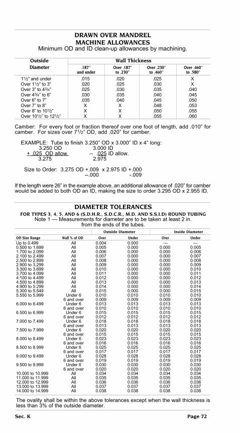
DRAWn oVeR MAnDReLMAcHine ALLoWAnceS
Minimum OD and ID clean-up allowances by machining.
outside Wall thickness Diameter .187” over .187” over .230” over .460” and under to .230” to .460” to .580”
11/2” and under .015 .020 .025 X Over 11/2” to 3” .020 .025 .030 X Over 3” to 43/4” .025 .030 .035 .040 Over 43/4” to 6” .030 .035 .040 .045 Over 6” to 7” .035 .040 .045 .050 Over 7” to 8” X X .048 .053 Over 8” to 101/2” X X .050 .055 Over 101/2” to 121/2” X X .055 .060
Camber: For every foot or fraction thereof over one foot of length, add .010” for camber. For sizes over 71/2” OD, add .020” for camber.
EXAMPLE: Tube to finish 3.250” OD x 3.000” ID x 4” long: 3.250 OD 3.000 ID + .025 OD allow. -- .025 ID allow. 3.275 2.975 Size to Order: 3.275 OD +.009 x 2.975 ID +.000 --.000 -.009
If the length were 26” in the example above, an additional allowance of .020” for camber would be added to both OD an ID, making the size to order 3.295 OD x 2.955 ID.
DiAMeteR toLeRAnceSFoR tYpeS 3, 4, 5, AnD 6 (S.D.H.R., S.D.c.R., M.D. AnD S.S.i.D) RounD tubing
Note 1 — Measurements for diameter are to be taken at least 2 in. from the ends of the tubes.
outside Diameter inside Diameter
oD Size Range Wall % of oD over under over underUp to 0.499 All 0.004 0.000 --- ---0.500 to 1.699 All 0.005 0.000 0.000 0.0051.700 to 2.099 All 0.006 0.000 0.000 0.0062.100 to 2.499 All 0.007 0.000 0.000 0.0072.500 to 2.899 All 0.008 0.000 0.000 0.0082.900 to 3.299 All 0.009 0.000 0.000 0.0093.300 to 3.699 All 0.010 0.000 0.000 0.0103.700 to 4.099 All 0.011 0.000 0.000 0.0114.100 to 4.499 All 0.012 0.000 0.000 0.0124.500 to 4.899 All 0.013 0.000 0.000 0.0134.900 to 5.299 All 0.014 0.000 0.000 0.0145.300 to 5.549 All 0.015 0.000 0.000 0.0155.550 to 5.999 Under 6 0.010 0.010 0.010 0.010 6 and over 0.009 0.009 0.009 0.0096.000 to 6.499 Under 6 0.013 0.013 0.013 0.013 6 and over 0.010 0.010 0.010 0.0106.500 to 6.999 Under 6 0.015 0.015 0.015 0.015 6 and over 0.012 0.012 0.012 0.0127.000 to 7.499 Under 6 0.018 0.018 0.018 0.018 6 and over 0.013 0.013 0.013 0.0137.500 to 7.999 Under 6 0.020 0.020 0.020 0.020 6 and over 0.015 0.015 0.015 0.0158.000 to 8.499 Under 6 0.023 0.023 0.023 0.023 6 and over 0.016 0.016 0.016 0.0168.500 to 8.999 Under 6 0.025 0.025 0.025 0.025 6 and over 0.017 0.017 0.017 0.0179.000 to 9.499 Under 6 0.028 0.028 0.028 0.028 6 and over 0.019 0.019 0.019 0.0199.500 to 9.999 Under 6 0.030 0.030 0.030 0.030 6 and over 0.020 0.020 0.020 0.02010.000 to 10.999 All 0.034 0.034 0.034 0.03411.000 to 11.999 All 0.035 0.035 0.035 0.03512.000 to 12.999 All 0.036 0.036 0.036 0.03613.000 to 13.999 All 0.037 0.037 0.037 0.03714.000 to 14.999 All 0.038 0.038 0.038 0.038
The ovality shall be within the above tolerances except when the wall thickness is less than 3% of the outside diameter.
Sec. K page 72

DRAWn oVeR MAnDReLWALL tHicKneSS toLeRAnceS
outside Diameter A
Wall 3/8 to 7/8, incl over 7/8 to 17/8, over 17/8 to 33/4 over 3/4
thickness include include to 15, incl.
In.A Bwg.B Wall Thickness Tolerances, in., A,C +/-
+ - + - + - + -
0.035 20 0.002 0.002 0.002 0.002 0.002 0.002 ---
0.049 18 0.002 0.002 0.002 0.003 0.002 0.003 --- ---
0.065 16 0.002 0.002 0.002 0.003 0.002 0.003 0.004 0.004
0.083 14 0.002 0.002 0.002 0.003 0.003 0.003 0.004 0.005
0.095 13 0.002 0.002 0.002 0.003 0.003 0.003 0.004 0.005
0.109 12 0.002 0.003 0.002 0.004 0.003 0.003 0.005 0.005
0.120 11 0.003 0.003 0.002 0.004 0.003 0.003 0.005 0.005
0.134 10 --- --- 0.002 0.004 0.003 0.003 0.005 0.005
0.148 9 --- --- 0.002 0.004 0.003 0.003 0.005 0.005
0.165 8 --- --- 0.003 0.004 0.003 0.004 0.005 0.006
0.180 7 --- --- 0.004 0.004 0.003 0.005 0.006 0.006
0.203 6 --- --- 0.004 0.005 0.004 0.005 0.006 0.007
0.220 5 ---- --- 0.004 0.006 0.004 0.006 0.007 0.007
0.238 4 --- --- 0.005 0.006 0.005 0.006 0.007 0.007
0.259 3 --- --- 0.005 0.006 0.005 0.006 0.007 0.007
0.284 2 --- --- 0.005 0.006 0.005 0.006 0.007 0.007
0.300 1 --- --- 0.006 0.006 0.006 0.006 0.008 0.008
0.320 --- --- 0.007 0.007 0.007 0.007 0.008 0.008
0.344 --- --- 0.008 0.008 0.008 0.008 0.009 0.009
0.375 --- --- --- --- 0.009 0.009 0.009 0.009
0.400 --- --- --- --- 0.010 0.010 0.010 0.010
0.438 --- --- --- --- 0.011 0.011 0.011 0.011
0.460 --- --- --- --- 0.012 0.012 0.012 0.012
0.480 --- --- --- --- 0.012 0.012 0.012 0.012
0.531 --- --- --- --- 0.013 0.013 0.013 0.013
0.563 --- --- --- --- 0.013 0.013 0.013 0.013
0.580 --- --- --- --- 0.014 0.014 0.014 0.014
0.600 --- --- --- --- 0.015 0.015 0.015 0.015
0.625 --- --- --- --- 0.016 0.016 0.016 0.016
0.650 --- --- --- 0.017 0.017 0.017 0.017
Straightness refer to page 69
A 1 in. = 25.4 mm.B Birmingham Wire GageC Where the ellipsis (---) appears in this table, the tolerance is not addressed.
Sec. K page 73

DRAWn oVeR MAnDReL
Special Smooth iD Hydraulic cylinder tubing
Special Smooth ID Tubing is a welded steel tubing that has been specially pro-cessed to produce an extra fine inside finish. Flat-rolled steel with its closely con-trolled tolerances is formed and electric-resistance welded into a tube. The welding flash is trimmed and the tube is normalized to insure a uniform and ductile structure. A final drawing over a highly polished mandrel produces the fine finish on the inside surface as well as uniform tolerances. Each length of tubing is subjected to non-destructive testing to insure quality of product.
Special Smooth ID Tubing can in many applications eliminate such costly opera-tions as honing and boring. It is furnished to meet the following maximum average micro-inch finish:
Maximum Average Microinch Readings on inside Surface
Wall thickness outside Diameter 1” to 21/2” over 21/2” over 41/2” over 7”
to 41/2” to 7” to 11”
.065” and under 40 40 --- --- Over .065” to .150” 45 50 55 --- Over .150” to .187” 50 60 70 --- Over .187” to .225” 55 70 80 90 Over .225” to .312” 70 80 90 100 Over .312” to .400” --- 90 100 110 Over .400” to .480” --- 100 110 120 Over .480” to .580” --- 110 120 130
toLeRAnceS — Special Smooth ID is ordered to one-half standard ID Tolerances shown in the Diameter Tolerance table shown on Page 72 of this section. Straightness tolerances are shown on Page 69 of ths section.
StocK SiZeS
Refer to listing on Pages 4-64 of this section, where availability of this material is indicated in the CARBON column by the abbreviation SS.
Sec. K page 74Sec. K page 74

1010/1020 coLD DRAWn butt WeLDeD tubing
AStM A 512 conDition -- cDSR
This tubing is cold drawn to size from hot rolled, continuous welded material. The cold drawing operations is identical in every respect with the method used in producing seamless mechanical tubing. Material in regular stock is mandrel drawn. However, Butt Welded Tubing is available drawn on the outside only for use where the inside dimension is not important; information on such material will be furnished upon request.
AnALYSiS carbon Manganese phosphorus Sulphur .05/.15 .30/.60 .040 Max. .050 Max.
MecHAnicAL pRopeRtieS — Cold Drawn Butt Welded Tubing is usually furnished in a finish annealed condition. The data in the following table indicate approximate properties and represent average values, since individual cases are affected by the amount of reduction of outside diameter and wall thickness in the cold drawing process.
tensile Yield
Strength Strength elongation Rockwell b
(psi) (psi)
65,000 50,000 20% 76
Size (oD) inches outside Diameter inside Diameter Wall thickness over under over under over under
under 1/2 .004 .000 .000 .010 121/2% 121/2% Walls under .156 1/2 to 11/2” .005 .000 .000 .005 10% 10% Walls under .156 Walls .156 & over .005 .000 .000 .005 7% 7% 11/2” and over .010 .000 --- .010 10% 10% Walls under .156 Walls .156 & over .010 .000 .000 .010 7% 7%
Straightness tolerances are shown on Page 69 of this section.
StocK SiZeSRefer to listing on Pages 4-64 of this section, where availability of Cold Drawn Butt Welded Tubing is indicated in the CARBON column by the abbreviation CDBW.
This product is made in over 600 sizes, and sizes not regularly carried in stock can be furnished promptly from the mill. Also, other analyses are available, including 1018, 1020, 1025, 1030, 1110, 1115 and 1117.
Although stocks consist mainly of round tubing, this product is also made in Squares, Rectangles, Ovals, and other shapes. We invite your inquiries for such special sections.
Sec. K page 75Sec. K page 75

1008/10/20 eLectRic ReSiStAnceWeLDeD MecHAnicAL tubing
AStM A 513, tYpeS 1 & 2
Electric Resistance Welded Mechanical Tubing is available generally in the 1008 and 1020 analyses. It is manufactured by forming flat rolled steel into a tubular shape and welding the edges. The flash is always removed from the outside of the tube. Round tubing 11/4” OD and over is carried with inside flash controlled to a maximum height of .010. Round tubing smaller than 11/4” OD is generally carried flash in.
Electric Resistance Welded Mechanical Tubing is available in a wide range of diam-eters but is confined to relatively thin walls. Tubes with walls .065” and thinner are generally produced from Cold Rolled Strip. Tubes with walls heavier than .065” are generally produced from Hot Rolled and Pickled Strip.
This tubing responds to the common fabrication techniques used for low carbon steels, such as bending, swaging, welding, machining, etc.
AnALYSiS carbon Manganese phosphorus (Max.) Sulphur (Max.) 1008 .010 Max .50 Max. .030 .035 1010 .05/.15 .30/.60 .040 .050 1020 .015/.25 .30/.60 .040 .050
MecHAnicAL pRopeRtieS — The following typical properties apply:
tensile Yield oD Wall Strength Strength elongation Rockwell b (psi) (psi)
1010 cold Rolled 3/4” and smaller All 48,000 40,000 15% 65 Over 3/4” 20-16 Ga. 45,000 35,000 25% 63 Over 3/4” 15 Ga. And hvr. 45,000 35,000 30% 60 1010 Hot Rolled 3/4” and smaller 16-14 Ga. 48,000 40,000 12% 65 Over 3/4” 16-14 Ga. 48,000 35,000 25% 63 Over 3/4” 13 Ga. And hvr. 45,000 32,000 35% 60 1020 cold Rolled 3/4” and smaller All 55,000 40,000 15% 70 Over 3/4” 20-16 Ga. 50,000 38,000 20% 68 Over 3/4” 15 Ga. And hvr. 50,000 38,000 30% 65 1020 Hot Rolled 3/4” and smaller All 55,000 40,000 12% 70 Over 3/4” 16-14 Ga. 52,000 38,000 20% 68 Over 3/4” 13 Ga. and hvr. 50,000 36,000 30% 65
toLeRAnceS — Refer to Pages 77-78 of this section.
StocK SiZeSRefer to listing on Pages 4-64 of this section, where availability is indicated in the CARBON column by the abbreviations cReW (Cold Rolled Electric Welded) and HReW (Hot Rolled Electric Welded).
Sec. K page 76
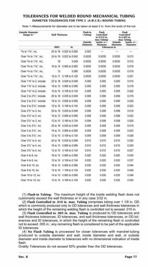
toLeRAnceS FoR WeLDeD RounD MecHAnicAL tubingDiAMeteR toLeRAnceS FoR tYpe 2 (A.W.c.R.) RounD tubing
Note 1–Measurements for diameter are to be taken at least 2 in. from the ends of the tub
outside Diameter Flash-in Flash Flash Range in A Wall thickness -tubingb controlled controlledD to 0.010 in. to 0.005 in. max tubingc max tubing outside inside +/— outside inside +/— Diameter Diameter Diameter Diameter bWg in. tolerances in.
5/8 to 11/8”, inc, 24 to 16 0.022 to 0.065 0.003 --- --- ---
Over 5/8 to 11/8”, inc, 24 to 19 0.022 to 0.042 0.0035 0.0035 0.0035 0.013
Over 5/8 to 11/8”, inc, 18 0.049 0.0035 0.0035 0.0035 0.015
Over 5/8 to 11/8”, inc, 16 to 14 0.065 to 0.083 0.0035 0.0035 0.0035 0.019
Over 3/4 to 11/8”, inc, 13 0.095 0.0035 0.0035 0.0035 0.019
Over 7/8 to 11/8”, inc, 12 to 11 0.109 to 0.120 0.0035 0.0035 0.0035 0.021
Over 11/8” to 2, include 22 to 18 0.028 to 0.049 0.005 0.005 0.005 0.015
Over 11/8” to 2, include 16 to 13 0.065 to 0.095 0.005 0.005 0.005 0.019
Over 11/8” to 2, include 12 to 10 0.109 to 0.134 0.005 0.005 0.005 0.022
Over 2 to 21/2”, include 20 to 18 0.035 to 0.049 0.006 0.006 0.006 0.016
Over 2 to 21/2”, include 16 to 13 0.065 to 0.095 0.006 0.006 0.006 0.020
Over 2 to 21/2”, include 12 to 10 0.109 to 0.134 0.006 0.006 0.006 0.023
Over 21/2” to 3, inc 20 to 18 0.035 to 0.049 0.008 0.008 0.008 0.018
Over 21/2” to 3, inc 16 to 13 0.065 to 0.095 0.008 0.008 0.008 0.022
Over 21/2” to 3, inc 12 to 10 0.190 to 0.134 0.008 0.008 0.008 0.025
Over 3 to 31/2”, inc 20 to 18 0.035 to 0.049 0.009 0.009 0.009 0.019
Over 3 to 31/2”, inc 16 to 13 0.065 to 0.095 0.009 0.009 0.009 0.023
Over 3 to 31/2”, inc 12 to 10 0.109 to 0.134 0.009 0.009 0.009 0.026
Over 31/2” to 4, inc 20 to 18 0.035 to 0.049 0.010 0.010 0.010 0.020
Over 31/2” to 4, inc 16 to 13 0.065 to 0.095 0.010 0.010 0.010 0.024
Over 31/2” to 4, inc 12 to 10 0.109 to 0.134 0.010 0.010 0.010 0.027
Over 4 to 6, inc 16 to 13 0.065 to 0.095 0.020 0.020 0.020 0.034
Over 4 to 6, inc 12 to 10 0.109 to 0.134 0.020 0.020 0.020 0.037
Over 8 to 10, inc 16 to 13 0.065 to 0.095 0.030 0.030 0.030 0.044
Over 8 to 10, inc 12 to 10 1.109 to 0.134 0.030 0.030 0.030 0.049
Over 10 to 12, inc 14 to 13 0.083 to 0.095 0.035 0.035 0.035 0.049
Over 10 to 12, inc 12 to 10 0.109 to 0.134 0.035 0.035 0.035 0.054
(1) Flash-in tubing: The maximum height of the inside welding flash does not customarily exceed the wall thickness or in any case 3/32 in. (2) Flash controlled to .010 in. max. tubing comprises tubing over 1 1/8 in. OD which is commonly produced only to OD tolerances and wall thickness tolerances in which the height of the remaining welding flash is controlled not to exceed .010 in. (3) Flash controlled to .005 in. max. tubing is produced to OD tolerances and wall thickness tolerances, ID tolerances, and wall thickness tolerances, or OD tol-erances and ID tolerances, in which the height of the remaining flash in controlled not to exceed .005 in.; any remaining flash is considered to be part of the applicable ID tolerances. (4) no Flash tubing is processed for closer tolerances with mandrel-tubing produced to outside diameter and wall, inside diameter and wall, or outside diameter and inside diameter to tolerances with no dimensional indication of inside flash.Ovality Tolerances do not exceed 50% greater than the OD tolerances.
Sec. K page 77

toLeRAnceS FoR WeLDeD RounD MecHAnicAL tubingDiAMeteR toLeRAnceS FoR tYpe 1 (A.W.H.R.) RounD tubing
Note 1–Measurements for diameter are to be taken at least 2 inches from the ends of the tub
outside Diameter Flash-in Flash Flash Range in A Wall thickness -tubing(1)(4) controlled controlled to 0.010 in. to 0.005 in. max. tubing(2)(4) max. tubing(3)(4)
outside inside +/— outside inside +/— Diameter Diameter Diameter Diameter bWgF in.A tolerances in.
1/2 to 11/8, include 16 to 10 0.065 to 0.134 0.0035 0.0035 0.0035 0.020 Over 11/8 to 2, inc 16 to 14 0.065 to 0.083 0.005 0.005 0.005 0.021 Over 11/8 to 2, inc 13 to 7 0.095 to 0.180 0.005 0.005 0.005 0.025 Over 11/8 to 2, inc 6 to 5 0.203 to 0.220 0.005 0.005 0.005 0.029 Over 11/8 to 2, inc 4 to 3 0.238 to 0.259 0.005 0.005 0.005 0.039 Over 2 to 21/2, inc 16 to 14 0.065 to 0.083 0.006 0.006 0.006 0.022 Over 2 to 21/2, inc 13 to 5 0.095 to 0.220 0.006 0.006 0.006 0.024 Over 2 to 21/2, inc 4 to 3 0.238 to 0.259 0.006 0.006 0.006 0.040 Over 21/2 to3, inc 16 to 14 0.065 to 0.083 0.008 0.008 0.008 0.024 Over 21/2 to3, inc 13 to 5 0.095 to 0.220 0.008 0.008 0.008 0.026 Over 21/2 to3, inc 4 to 3 0.238 to 0.259 0.008 0.008 0.008 0.040. Over 21/2 to3, inc 2 to 0.320 0.284 to 0.320 0.010 0.010 0.010 0.048 Over 3 to 31/2, inc 16 to 14 0.065 to 0.083 0.009 0.009 0.009 0.025 Over 3 to 31/2, inc 13 to 5 0.095 to 0.220 0.009 0.009 0.009 0.027 Over 3 to 31/2, inc 4 to 3 0.238 to 0.259 0.009 0.009 0.009 0.043 Over 3 to 31/2, inc 2 to 0.0360 0.284 to 0.360 0.012 0.012 0.012 0.050 Over 31/2 to 4, inc 16 to 14 0.065 to 0.083 0.010 0.010 0.010 0.026 Over 31/2 to 4, inc 13 to 5 0.095 to 0.220 0.010 0.010 0.010 0.028 Over 31/2 to 4, inc 4 to 3 0.238 to 0.259 0.010 0.010 0.010 0.044 Over 31/2 to 4, inc 2 to 0.500 0.284 to 0.500 0.015 0.015 0.015 0.053 Over 4 to 5, inc. 16 to 14 0.065 to 0.083 0.020 0.020 0.020 0.036 Over 4 to 5, inc. 13 to 5 0.095 to 0.220 0.020 0.020 0.020 0.045 Over 4 to 5, inc. 4 to 3 0.238 to 0.259 0.020 0.020 0.020 0.054 Over 4 to 5, inc. 2 to 0.500 0.284 to 0.500 0.020 0.020 0.020 0.058 Over 5 to 6, inc. 16 to 10 0.065 to 0.134 0.020 0.020 0.020 0.036 Over 5 to 6, inc. 9 to 5 0.148 to 0.220 0.020 0.020 0.020 0.040 Over 5 to 6, inc. 4 to 3 0.238 to 0.259 0.020 0.020 0.020 0.054 Over 5 to 6, inc. 2 to 0.500 0.284 to 0.500 0.020 0.020 0.020 0.058 Over 6 to 8, include 11 to 10 0.120 to 0.134 0.025 0.025 0.025 0.043 Over 6 to 8, include 9 to 5 0.148 to 0.220 0.025 0.025 0.025 0.045 Over 6 to 8, include 4 to 3 0.238 to 0.259 0.025 0.025 0.025 0.059 Over 6 to 8, include 2 to 0.500 0.284 to 0.500 0.025 0.025 0.025 0.063 Over 8 to 10, inc. 14 to 12 0.083 to 0.109 0.030 0.030 0.030 0.041 Over 8 to 10, inc. 11 to 10 0.120 to 0.134 0.030 0.030 0.030 0.043 Over 8 to 10, inc. 9 to 5 0.148 to 0.220 0.030 0.030 0.030 0.045 Over 8 to 10, inc. 4 to 3 0.238 to 0.259 0.030 0.030 0.030 0.059 Over 8 to 10, inc. 2 to 0.500 0.248 to 0.500 0.030 0.030 0.030 0.063 Over 10 to 12, inc 14 to 12 0.083 to 0.109 0.035 0.035 0.035 0.041 Over 10 to 12, inc 11 to 10 0.120 to 0.134 0.035 0.035 0.035 0.043 Over 10 to 12, inc 9 to 5 0.148 to 0.220 0.035 0.035 0.035 0.045 Over 10 to 12, inc 4 to 3 0.238 to 0.259 0.035 0.035 0.035 0.059 Over 10 to 12, inc 2 to 0.500 0.248 to 0.500 0.035 0.035 0.035 0.063
See (1) (2) (3) (4) at bottom of page 77.
Sec. K page 78

toLeRAnceS FoR WeLDeD RounD MecHnicAL tubingWall thickness tolerances
coLD RoLLeD outSiDe DiAMeteR oF tube in incHeS
Wall 3/8 to 7/8 over 7/8 to 17/8” over 17/8” to 33/4” over 33/4” to 5 over 5 to 6 (bMg) over* under over* under over* under over* under over* under 22 .000 .003 .000 .003 20 .000 .004 .000 .004 .000 .004 18 .000 .004 .000 .005 .000 .005 16 .000 .004 .000 .005 .000 .005 .002 .006 .002 .007 13-14 .000 .004 .000 .005 .000 .006 .002 .007 .002 .007 9-12 .000 .006 .000 .006 .003 .007 .003 .007 8 .000 .007 .000 .007 .003 .008 .003 .0100
*The following additional tolerances apply to the over limits shown above due to the crown of the flat rolled steel:
outside Diameter Wall thickness plus tolerance 3/8 to 17/8” .025 to .064 .0015 Over .064 to .016, Incl. .002 Over 17/8” to 33/4” .025 to .064 .002 Over .064 to .165, Incl. .0025 Over 33/4” to 63/4” Over .064 to .165, include .003
Hot RoLLeD outSiDe DiAMeteR oF tube in incHeS
Wall 3/8 to 1 over 1 to 115/16” over 115/16” to 33/4” over 33/4” to 41/2” over 41/2” to 6 (bWg) over* under over* under over* under over* under over* under 16 .002 .006 .002 .008 .002 .008 .002 .010 .002 .010 13-14 .002 .006 .002 .008 .002 .008 .003 .010 .002 .012 12 .002 .006 .002 .008 .002 .008 .005 .010 .004 .012 10-11 .002 .008 .002 .008 .002 .008 .005 .010 .004 .012 7-9 .002 .008 .002 .008 .005 .011 .005 .012 6 .002 .010 .002 .010 .005 .012 .005 .013 5 .005 .012 .002 .010 .005 .012 .005 .013 4 .010 .018 .010 .018 .010 .018
*The following additional tolerances apply to the over limits shown above due to the crown of the flat rolled steel:
outside Diameter plus tolerance 3/4 to 1, inc. .002 Over 1 to 115/16”, include. .003 Over 115/16” to 33/4”, include. .004
StRAigHtneSS toLeRAnceS Straightness tolerance is customarily .030 inch per three feet of length. The straight-
ness variation is determined by placing the tube on a surface plate with both ends touching the plate. The point of maximum deflection of the tube from the surface plate should be not more than .030 inch per three feet of length when measured with a feeler gauge. For lengths above one foot, the straightness tolerance is .010 in.
Sec. K page 79

4130 ALLoY SteeL SeAMLeSS MecHAnicAL tubing(Aircraft)
AMS 6371
4130 is a chromium-molybdenum general purpose alloy steel tubing that is weldable and is capable of developing good strength. For years it has been the standard of the aircraft industry. It is manufactured to meet the rigid standards of aircraft quality and is suitable for the fabrication of parts which may be subjected to magnetic particle (magnaflux) inspection.
AnALYSiS c Mn p (Max.) S (Max.) Si cr Mo .28/.33 .40/.60 .025 .025 .15/.35 .80/1.10 .15/.25
AppLicAtionS — It is used for parts with section thicknesses of 1/2” or less at the time of heat treatment which require a through hardening steel capable of develop-ing hardness as high as Rockwell C 35 when properly hardened and tempered. It may be used for parts of greater section thickness where proportionately lower hardness or strength levels are required.
HARDenAbiLitY — This grade has a hardenability of Rockwell C 35 minimum at 5/16 and Rockwell C 28 minimum at 8/16 when normalized at 1700ºF and aus-tenitized at 1600ºF.
toLeRAnceS — Refer to pages 67-69 of this section.
StocK SiZeSRefer to listing on Pages 4-64 of this section, where availability of this product is indicated in the ALLOY column by the number 4130.
4135 ALLoY SteeL SeAMLeSS MecHAnicAL tubing(Aircraft)
AMS 6372
4135 is a chromium-molybdenum alloy steel tubing, capable of developing higher strength than 4130. It is manufactured by the electric furnace process to meet the rigid standards of the aircraft industry, and it is suitable for the fabrication of parts which may be subjected to magnetic particle (magnaflux) inspection.
AnALYSiS c Mn p (Max.) S (Max.) Si cr Mo .33/.38 .70/.90 .025 .025 .20/.35 .80/1.10 .15/.25
AppLicAtionS — It is used for parts with section thicknesses of 3/4” or less at the time of heat treatment which require a through hardening steel that will develop a hardness as high as Rockwell C 40 when properly hardened and tempered. It may be used for parts of greater section thickness where proportionately lower hardness or strength levels are required.
HARDenAbiLitY — this grade has a hardenability of Rockwell C 45 minimum at 6/16 and Rockwell C 40 minimum at 9/16 when normalized at 1700ºF and austen-itized at 1600ºF.
toLeRAnceS — Refer to pages 67-69 of this section.
Sec. K page 80

4140 ALLoY SteeL
SeAMLeSS MecHAnicAL tubing(Aircraft)
AMS 6381
4140 is a medium carbon chromium-molybdenum alloy steel tubing. It is manufac-tured by the electric furnace process to meet the rigid standards of the aircraft industry, and it is suitable for the fabrication of parts which may be subjected to magnetic par-ticle (magnaflux) inspection. It responds readily to heat treatment and is capable of developing a higher hardness than 4130 and 4135.
AnALYSiS c Mn p (Max.) S (Max.) Si cr Mo .38/.43 .75/1.00 .025 .025 .20/.35 .80/1.10 .15/.25
AppLicAtionS — It is used for parts with section thicknesses of 1/2” or less at the time of heat treatment which require a through hardening steel capable of develop-ing hardness as high as Rockwell C 50 when properly hardened and tempered. It may be used for parts of greater section thickness where proportionately lower hardness or strength levels are required.
HARDenAbiLitY — This grade has a hardenability of Rockwell C 50 minimum at 6/16 and Rockwell C 44 minimum at 9/16 when normalized at 1700ºF and aus-tenitized at 1550ºF.
toLeRAnceS — Refer to pages 67-69 of this section.
StocK SiZeSRefer to listing on Pages 4-64 of this section, where availability of this product is indicated in the ALLOY column by the number 4140.
4340 ALLoY SteeL
SeAMLeSS MecHAnicAL tubing(Aircraft)
AMS 6415
4340 is a chromium-nickel-molybdenum alloy steel manufactured by the electric fur-nace process to meet the rigid standards of the aircraft industry, and it is suitable for the fabrication of parts which may be subjected to magnetic particle (magnaflux) inspection. With its high alloy content, it possesses greater hardenability than the 4100 series alloys, and this advantage is realized where high strength is required in heavy sections.
AnALYSiS c Mn p (Max.) S (Max.) Si cr n Mo .38/.43 .65/.85 .025 .025 .15/.35 .70/.90 1.65/2.00 .20/.30
AppLicAtionS — It is used for parts with section thicknesses of 31/2” or less at the time of heat treatment which require a through hardening steel capable of developing hardness as high as Rockwell C 30 when properly hardened and tempered. It may be used for parts of greater section thickness where proportionately lower hardness or strength levels are required.
HARDenAbiLitY — This grade has a hardenability of Rockwell C 50 minimum at 20/16 when normalized at 1700ºF and austenitized at 1525ºF.
toLeRAnceS — Refer to pages 67-69 of this section.
StocK SiZeSRefer to listing on Pages 4-64 of this section, where availability of this product is indicated in the ALLOY column by the number 4130.
Sec. K page 81

4130/4140
cHRoMe-MoLYbDenuM
MecHAnicAL tubeS
AStM A 519 unS g41300/g41400
These grades are commonly used in the Stress Relieved or annealed condition for mechanical parts which are to heat treated after machining. The heat treated materials are intended for use in oilfield applications where strength combined with ductility is required.
AnALYSiS c Mn p(Max.)* S(Max.)* Si cr Mo 4130 .28/.33 .40/.60 .040 .040 .15/.35 .80/1.10 .15/.25 4140 .38/.43 .75/1.10 .040 .040 .15/.35 .80/1.10 .15/.25
*Special grades may require reduced levels of these elements.
MecHAnicAL pRopeRtieS — Stress Relieved/Annealed (Typical Only)
tensile Yield Strength Strength elongation bHn (Ksi) (Ksi) 2” Min.
4130 Cold Drawn 110 95 15% 228 4130 Hot Finish 90 70 20% 187 4140 Cold Drawn 120 100 10% 245 4140 Hot Finish 120 90 20% 245
Heat Treated Condition (both grades) NACE MRO175
L-80 Properties: 95 ksi minimum tensile, 80-110 ksi yield, 15% minimum elonga-tion, 237 maximum BHNP-110 Properties: 125 ksi minimum tensile, 110-140 ksi yield, 12% minimum elonga-tion, 341 maximum BHN
MAcHinAbiLitY — These grades have a machinability rating of approximately 70% of 1212 in the SR or Annealed condition. The machinability of these grades in the HT condition is approximately 60%.
WeLDAbiLitY — These grades require preheating and postheating treatments to avoid cracking.
noRMALiZing — Heat to 1600-1700ºF. Cool in air. Average Brinell Hardness is 167.
AnneALing — Heat to 1500-1600ºF. Cool slowly in furnace. Average Brinell Hardness is 149.
HARDening — Hardening range 1550-1700ºF. 4130 for water quench and 4140 for oil or polymer quench. Tempering temperature is dependent on desired proper-ties. Tempering range is 400-1300ºF.
Sec. K page 82

4340 ALLoY SteeL
AnneALeD SeAMLeSS MecHAnicAL tubing(commercial Quality)
AStM A 519 unS g43400
This grade is a nickel-chromium molybdenum alloy steel. It is richer in alloy content than the 4100 series, and thus possesses deeper hardenability characteristics. This advantage is realized where high strength is required in heavy sections. Such high hardenability insures maximum toughness and ductility at the required strength level, making it ideal for highly stressed parts. It maintains its strength and ductility at relatively high temperatures. Thus, for high strength in heavy section or for highly stressed parts operating under severe conditions, this is the analysis to use.
AnALYSiS c Mn p (Max.) S Si cr ni Mo .38/.43 .60/.80 .035 .040 .15/.35 .70/.90 1.65/2.00 .20/.30
AppLicAtionS — It is used for such applications as oil well fishing tools, perforat-ing gun bodies, bushings, high-pressure fittings, as well as miscellaneous machin-ing parts requiring high strength and toughness.
toLeRAnceS — Refer to Pages 66-69 of this section.
MecHAnicAL pRopeRtieS — (Typical)
tensile Yield elongation Reduction brinell izod Strength Strength 2” Min. of Area of Area of Area (psi) (psi)
Annealed 110,000 66,000 23% 49% 197 25
StocK SiZeSRefer to listing on Pages 4-64 of this section, where availability of this product is indicated in the ALLOY column by the number 4340.
Sec. K page 83

tYpe 304 StAinLeSS SteeL tubing
AMS 5639AStM A 511AStM A 269
Type 304 is a low carbon “18-8” chromium-nickel stainless steel. It combines excellent physical properties with remarkable resistance to many corrosive agents encountered in domestic and industrial use. The low carbon content provides good corrosion resistance in welded construction where subsequent solution heat treatment is not practical. It has good heat resistance and maintains its strength at elevated temperatures up to 800º F. It is non-magnetic in the annealed condition and not hardenable by heat treatment. Both hardness and tensile strength can be increased by cold working.
AnALYSiS c (Max.) Mn (Max.) p (Max.) S (Max.) Si (Max.) cr ni Mo (Max.) cu (Max.) .08 2.00 .040 .030 .75 18.00/20.00 8.00/11.00 .75 .75
AppLicAtionS — It is used in the fabrication of parts where corrosion resistance and good physical properties and heat resistance up to 800ºF are required. It is widely used in such industries as dairy, beverage, and other food products, where the highest degree of sanitation and cleanliness is of prime importance. Parts for handling acetic, nitric, and citric acids, organic and inorganic chemicals, dyestuffs, crude and refined oils, etc., are fabricated from this material. Because of its lack of magnetism it is highly desirable for instruments.
coRRoSion ReSiStAnce — Maximum corrosion resistance is obtained in the annealed condition. Intergranular corrosion may occur when material is heated within or cooled through the range of 800º to 1500ºF.
ReSiStAnce to ScALing — Excellent scale resistance at temperatures up to 1600ºF in continuous service. Chromium-nickel grades have a high coefficient of expansion, which should be considered in designing.
pHYSicAL pRopeRtieS — The following may be considered as representative of this grade:
tensile Yield elongation Reduction Rockwell b Strength Strength 2” Min. of Area (psi) (psi)
85,000 35,000 60% 70% 90 Max.
toLeRAnceS — Refer to Pages 89-90 of this section.
StocK SiZeSRefer to listing on Page 4-64 of this section, where availability of this product is indicated in the STAINLESS column by the number 304.
Sec. K page 84

tYpe 316 StAinLeSS SteeL tubing
AMS 5648AStM A 511AStM A 269
Type 316 is “18-8” chromium-nickel stainless steel modified by the addition of molybdenum, which greatly increases its corrosion resistance as well as its physical properties at elevated temperatures. At elevated temperatures it has strength which is slightly higher than the basic 18-8 grades. It is non-magnetic in the annealed condition and not hardenable by heat treatment. Both hardness and strength are increased by cold working.
AnALYSiS c (Max.) Mn p (Max.) S (Max.) Si (Max.) cr ni Mo cu (Max.) .08 1.25/2.00 .040 .030 .75 17.00/18.00 11.00/14.00 2.00/3.00 .75
AppLicAtionS — Type 316 is used in the fabrication of parts where corrosion resistance and heat resistance up to 1600º F are required. Because it possesses the highest creep and tensile strength at elevated temperatures of any of the more commonly used stainless steels, it finds extensive use where the combina-tion of high strength and good corrosion resistance at elevated temperatures is required. In aircraft applications, Type 316 is used for parts requiring good corrosion resistance and low magnetic permeability.
coRRoSion ReSiStAnce — Type 316 is more resistant to atmospheric and general corrosive conditions than any of the other standard stainless steels. It has good resistance to the corrosive effects of sulphates, phosphates, and other salts, as well as reducing acids such as sulphuric, sulphurous, and phosphoric. It is less susceptible to pitting in applications where acetic acid vapors or solutions of chlorides, bromides, or iodides are encountered. When heated to the temperature range 800º-1500ºF, or when slowly cooled through this range, this grade is sub-jected to intergranular corrosion.
ReSiStAnce to ScALing — Excellent scale resistance to temperatures up to 1600ºF in continuous service.
pHYSicAL pRopeRtieS — The following may be considered as representative of this grade:
tensile Yield elongation Reduction Rockwell b Strength Strength 2” Min. of Area (psi) (psi)
80,000 35,000 60% 70% 90 Max.
toLeRAnceS — Refer to Pages 89-90 of this section.
StocK SiZeSRefer to listing in Pages 4-64 of this section, where availability of this product is indicated in the STAINLESS column by the number 316.
Sec. K page 85

tYpe 321 StAinLeSS SteeL tubing
AMS 5645AStM A 269MiL-t-6737
Type 321 is an “18-8” chromium-nickel stainless steel modified with the addition of titanium. It is designed to overcome the susceptibility to carbide precipitation with resulting intergranular corrosion that is common to the other austenitic stainless steels after exposure to temperatures of 800º to 1500ºF. It is non-magnetic in the annealed condition and not hardenable by heat treatment.
AnALYSiS c (Max.) Mn (Max.) p (Max.) S (Max.) Si (Max.) cr ni ti Mo (Max.) cu (Max.)
.08 2.00 .040 .030 1.00 17.00/20.00 9.00/13.00 6xC Min/.070 Max .75 .50
AppLicAtionS — It is used for parts and assemblies requiring good corrosion, heat, and oxidation resistance up to approximately 1500ºF, particularly where processing is by welding. At elevated temperatures its use is limited to low stress applications.
coRRoSion ReSiStAnce — Maximum corrosion resistance is obtained in the annealed condition. It is resistant to intergranular corrosion. Its general corrosion resistance is somewhat less than that of Type 304.
ReSiStAnce to ScALing — Type 321 has excellent scale resistance at tempera-tures of up to 1650ºF in continuous service and 1500ºF in intermittent service.
pHYSicAL pRopeRtieS — The following may be considered as representative of this grade:
tensile Yield elongation Reduction Rockwell b Strength Strength 2” Min. of Area (psi) (psi)
85,000 35,000 55% 65% 90 Max.
toLeRAnceS — Refer to Pages 89-90 of this section.
StocK SiZeSRefer to listing in Pages 4-64 of this section, where availability of this product is indicated in the STAINLESS column by the number 321.
Sec. K page 86

tYpe 347 StAinLeSS SteeL tubing
AMS 5646AStM A 269
Type 347 is an “18-8” chromium-nickel stainless steel modified with the addition of columbium or columbium-tantalum. Like 321, it is designed to overcome the dan-gers of intergranular corrosion common to other austenite stainless steels during and after exposure to temperatures of 800º to 1500ºF. It is non-magnetic in the annealed condition and not hardenable by heat treatment.
AnALYSiS c (Max.) Mn (Max.) p (Max.) S (Max.) Si (Max.) cr ni cb+ta Mo (Max.) cu (Max.)
.08 2.00 .040 .030 .75 17.00/19.00 9.00/12.00 10xC Min./1.00 Max. .75 .50
AppLicAtionS — It is used for heavy welded assemblies which cannot be annealed after welding. It is applied where operating conditions cause exposure within the temperature range of 800º to 1500ºF, and where corrosive conditions are severe. It is used to advantage in combatting corrosive cracking resulting from stress in cor-rosive media due to vibrations or other causes.
coRRoSion ReSiStAnce — Maximum corrosion resistance of Type 347 is obtained in the annealed condition. Its general corrosion resistance is somewhat less than for Type 304.
ReSiStAnce to ScALing — Type 347 has excellent scale resistance at tempera-tures of up to 1700ºF in continuous service and 1550ºF in intermittent service.
pHYSicAL pRopeRtieS — The following may be considered as representative of this grade:
tensile Yield elongation Reduction Rockwell b Strength Strength 2” Min. of Area (psi) (psi)
90,000 35,000 50% 65% 90 Max.
toLeRAnceS — Refer to Pages 89-90 of this section.
StocK SiZeSRefer to listing in Pages 4-64 of this section, where availability of this product is indicated in the STAINLESS column by the number 347.
Sec. K page 87
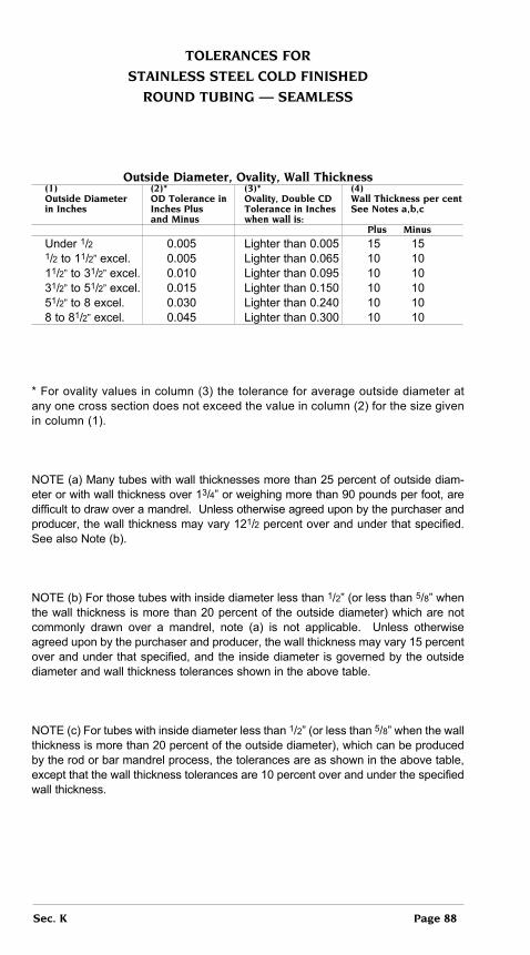
toLeRAnceS FoR
StAinLeSS SteeL coLD FiniSHeD
RounD tubing — SeAMLeSS
outside Diameter, ovality, Wall thickness (1) (2)* (3)* (4) outside Diameter oD tolerance in ovality, Double cD Wall thickness per cent in inches inches plus tolerance in inches See notes a,b,c and Minus when wall is: plus Minus
Under 1/2 0.005 Lighter than 0.005 15 15 1/2 to 11/2” excel. 0.005 Lighter than 0.065 10 10 11/2” to 31/2” excel. 0.010 Lighter than 0.095 10 10 31/2” to 51/2” excel. 0.015 Lighter than 0.150 10 10 51/2” to 8 excel. 0.030 Lighter than 0.240 10 10 8 to 81/2” excel. 0.045 Lighter than 0.300 10 10
* For ovality values in column (3) the tolerance for average outside diameter at any one cross section does not exceed the value in column (2) for the size given in column (1).
NOTE (a) Many tubes with wall thicknesses more than 25 percent of outside diam-eter or with wall thickness over 13/4” or weighing more than 90 pounds per foot, are difficult to draw over a mandrel. Unless otherwise agreed upon by the purchaser and producer, the wall thickness may vary 121/2 percent over and under that specified. See also Note (b).
NOTE (b) For those tubes with inside diameter less than 1/2” (or less than 5/8” when the wall thickness is more than 20 percent of the outside diameter) which are not commonly drawn over a mandrel, note (a) is not applicable. Unless otherwise agreed upon by the purchaser and producer, the wall thickness may vary 15 percent over and under that specified, and the inside diameter is governed by the outside diameter and wall thickness tolerances shown in the above table.
NOTE (c) For tubes with inside diameter less than 1/2” (or less than 5/8” when the wall thickness is more than 20 percent of the outside diameter), which can be produced by the rod or bar mandrel process, the tolerances are as shown in the above table, except that the wall thickness tolerances are 10 percent over and under the specified wall thickness.
Sec. K page 88

toLeRAnceS FoR StAinLeSS SteeL
RounD tubing — eLectRic WeLDeD
outside Diameter, ovality, Straightness outside Diameter oD tolerance in inches iD tolerance, in inches in inches plus and Minus plus and Minus
Up to 3/32 excl. .001 .001 3/32 to 3/16 excl. .0015 .0015 3/16 to 1/2 excl. .003 .005 1/2 to 1 excl. .004 .006 1 to 11/2” excl. .005 .007 11/2 to 2 excl. .006 .008 2 to 21/2” excl. .007 .010 21/2” to 31/2” excl. .010 .014 31/2” to 5 excl. .015 .020
NOTE 1. As applied to welded stainless steel tubing, ovality is the difference between maximum and minimum outside diameters measured at any one cross sec-tion. There is no additional tolerance for ovality on tubes having a nominal wall thickness of more than 3 percent of the OD.
NOTE 2. An ovality allowance of twice the OD tolerance, shown in the above table, is applied one-half plus and one-half minus to the OD, for tubes having a nominal wall thickness of 3 percent or less of the OD. The average of the maximum and minimum OD readings should fall within the OD tolerances as shown in the above table.
NOTE 3. For tolerances closer than those shown in the above table, the producer should be consulted.
NOTE 4. The straightness tolerance is 0.030” in 3 feet.
Wall thicknessplus and Minus
Wall thickness* 3/16” to 1” to under 2” to under 4” to 5” oD
inch bWg** under 1” oD 2” oD 4” oD
.025 23 .002 .003 -- -- .028 22 .003 .003 -- -- .023 21 .003 .003 .004 -- .035 20 .003 .003 .005 .005 .042 19 .003 .003 .005 .005 .049 18 .003 .003 .005 .005 .058 17 .004 .005 .005 .006 .065 16 .005 .005 .005 .006 .072 15 .005 .005 .006 .007 .083 14 .005 .005 .006 .007 .095 13 .005 .005 .006 .007 .109 12 .005 .006 .007 .007 .120 11 .005 .006 .007 .007 .134 10 -- -- .007 .007 .149 9 -- -- .008 .008 .165 8 -- -- .008 .008 * For intermediate wall thicknesses use the tolerances for the next heavier gauge.**Birmingham Wire Gauge.
Sec. K page 89

3003 ALuMinuM
DRAWn SeAMLeSS MecHAnicAL tubingAMS WW-t-700/2 AMS 4065 AStM b 210
3003 is the best known and the most widely used of all aluminum alloys. It is used where formability and weldability are both required, and where more strength is desired than is found in commercially pure aluminum. It is used for food and chemical handling equipment, gasoline and oil tanks, etc.
MecHAnicAL pRopeRtieS
temper tensile Strength (psi) Yield Strength (psi)
0 19,000 max. 16,000 average H14 20,000 min. 21,500 average
toLeRAnceS — Refer to page 94-96 of this section.
StocK SiZeSRefer to listing on Pages 4-64 of this section, where availability of this product is indicated in the ALUMINUM column by the symbols 3003-o (annealed) and 3003-H14 (1/2 hard).
2024 ALuMinuM DRAWn AnD eXtRuDeD
SeAMLeSS MecHAnicAL tubing
Drawn extruded AMS WW-t-700/3 AMS QQ-A-200/3 AStM b 210 (Formerly QQ-A-267) AMS 4088 AStM b 235 AMS 4152
2024 is one of the most commonly used heat treatable aluminum alloys. It is used where high strength is required and no welding is involved. Such applications include aircraft structures and hardware, screw machine products, aircraft fittings, etc.
MecHAnicAL pRopeRtieS
temper nominal tensile Yield elongation Diameter Strength Strength 2” Min. (psi) (psi) T3 All sizes 64,000 42,000 10%-16% T4 Up to 0.249 include. 57,000 42,000 12% .0250 to .0749 include. 60,000 44,000 12% 0.750 to 1.499 include. 65,000 46,000 10% 1.500 and over: 10% Up to 23 sq. in. include. 70,000 52,000 Over 25 to 32 sq. in. include 68,000 48,000 8%
toLeRAnceS — Refer to Pages 94-96 of this section.
StocK SiZeSRefer to listing on Pages 4-64 of this section, where availability of this product is indicated in the ALUMINUM column by the symbols 2024-t4 (heat treated) and 2024-t3 (heat treated and cold worked).
Sec. K page 90

5052 ALuMinuM
DRAWn SeAMLeSS MecHAnicAL tubingAMS WW-t-700/4 AMS 4070 AStM b 210
5052 is one of the strongest of the non-heat-treatable aluminum alloys. It is used where good workability, resistance to corrosion, high fatigue strength, and moderate static strength are required. Such applications include aircraft fuel and oil lines, fuel tank fittings, miscellaneous marine and transportation applications, as well as miscellaneous applications, in home appliances, and sheet metal components.
MecHAnicAL pRopeRtieS — The following mechanical properties apply in the “O” (annealed) temper:
tensile Strength (psi) Yield Strength (psi)
35,000 maximum 20,000 average 27,000 average
toLeRAnceS — Refer to Page 94-96 of this section.
StocK SiZeSRefer to listing on Pages 4-64 of this section, where availability of this product is indicated in the ALUMINUM column by the symbol 5052-o.
6061 ALuMinuMDRAWn AnD eXtRuDeD
SeAMLeSS MecHAnicAL tubing
Drawn extruded AMS WW-t-700/6 AMS QQ-A-200/8 AStM b 210 AStM b 241 AMS 4082 AMS 4150 6061 is the most versatile and one of the least expensive of the heat-treatable aluminum alloys. It is used where good strength and very good resistance to cor-rosion are required, and it is used to advantage where the method of fabrication is welding. Such applications include welded assemblies for marine and transportation equipment, aircraft components, etc.
MecHAnicAL pRopeRtieS
temper tensile Yield elongation Strength Strength 2” Min. (psi) (psi) O 22,000 max. 16,000 max. 16% min. T4 30,000 min. 16,000 min. 18% min. T6 38,000 min. 35,000 min. 10% min.
toLeRAnceS — Refer to Page 94-96 of this section.
StocK SiZeSRefer to listing on Pages 4-64 of this section, where availability of this product is indicated in the ALUMINUM column by the symbols 6061-o (annealed), 6061-t4 (heat treated and naturally aged), and 6061-t6 (heat treated and artificially aged).
Sec. K page 91
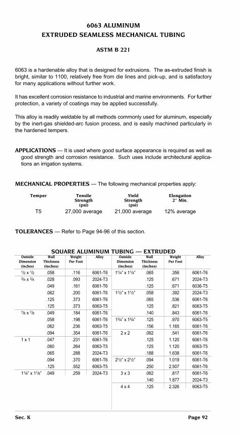
6063 ALuMinuM
eXtRuDeD SeAMLeSS MecHAnicAL tubing
AStM b 221
6063 is a hardenable alloy that is designed for extrusions. The as-extruded finish is bright, similar to 1100, relatively free from die lines and pick-up, and is satisfactory for many applications without further work.
It has excellent corrosion resistance to industrial and marine environments. For further protection, a variety of coatings may be applied successfully.
This alloy is readily weldable by all methods commonly used for aluminum, especially by the inert-gas shielded-arc fusion process, and is easily machined particularly in the hardened tempers.
AppLicAtionS — It is used where good surface appearance is required as well as good strength and corrosion resistance. Such uses include architectural applica-tions an irrigation systems.
MecHAnicAL pRopeRtieS — The following mechanical properties apply:
temper tensile Yield elongation Strength Strength 2” Min. (psi) (psi)
T5 27,000 average 21,000 average 12% average
toLeRAnceS — Refer to Page 94-96 of this section.
SQuARe ALuMinuM tubing — eXtRuDeD outside Wall Weight Alloy outside Wall Weight Alloy Dimension thickness per Foot Dimension thickness per Foot (inches) (inches) (inches) (inches)
1/2 x 1/2 .058 .116 6061-T6 11/4” x 11/4” .065 .356 6061-T6 3/4 x 3/4 .028 .093 2024-T3 .125 .671 2024-T3 .049 .161 6061-T6 .125 .671 6036-T5 .062 .200 6061-T6 11/2” x 11/2” .058 .392 2024-T3 .125 .373 6061-T6 .065 .536 6061-T6 .125 .373 6063-T5 .125 .821 6063-T5 7/8 x 7/8 .049 .184 6061-T6 .140 .843 6061-T6 .058 .198 6061-T6 13/4” x 13/4” .125 .970 6063-T5 .062 .236 6063-T5 .156 1.165 6061-T6 .094 .354 6061-T6 2 x 2 .062 .541 6061-T6 1 x 1 .047 .231 6061-T6 .125 1.120 6061-T6 .060 .264 6063-T5 .125 1.120 6063-T5 .065 .288 2024-T3 .188 1.638 6061-T6 .094 .370 6061-T6 21/2” x 21/2” .094 1.019 6061-T6 .125 .552 6063-T5 .250 2.507 6061-T6 11/8” x 11/8” .049 .259 2024-T3 3 x 3 .062 .817 6061-T6 .140 1.877 2024-T3 4 x 4 .125 2.326 6063-T5
Sec. K page 92

RectAnguLAR ALuMinuM tubing -- eXtRuDeD
outside Dimension Wall thickness Weight Alloy (inches) (inches) per Foot
3/4 X 3/8 .047 .116 6061-T6 1 X 1/2 .035 .119 6061-T6 .125 .373 6063-T5 11/2” X 3/4 .125 .598 6063-T5 11/2” X 1 .078 .451 6063-T5 .125 .671 6061-T6 .125 .671 6063-T5 2 x 1 .064 .436 6061-T6 .083 .528 6061-T6 .125 .821 6063-T5 2 x 11/2 .125 .970 6063-T5 2 x 11/4 .125 .970 6063-T5 3 x 1 .083 .775 6061-T6 3 x 11/4 .125 1.200 6061-T6 3 x 13/4 .125 1.345 6063-T5 3 x 2 .125 1.402 6063-T5 31/2 x 13/4 .125 1.494 6063-T5 4 x 11/2 .065 .837 2024-T3 4 x 13/4 .125 1.643 6063-T5 41/2 x 13/4 .125 1.793 6063-T5 5 x 11/4 .125 1.780 6061-T6 5 x 13/4 .125 1.942 6063-T5 5 x 2 .125 2.017 6063-T5
toLeRAnceS FoR SQuARe AnD RectAnguLAR ALuMinuM tubing — eXtRuDeD
WiDtH and DeptH toLeRAnceS2
incHeS — plus and Minus Specified Width Allowable Deviation Allowable Deviation of Width or Depth or Depth1 of Width or Depth at not at corners from Specified (inches) corners from Specified Width or Depth6
Width or Depth Square and Rectangular Square Rectangular
0.500-0.749 .012 .020 0.750-.0999 .014 .020 1.000-1.999 .018 .025 2.000-3.999 .025 .035 4.000-4.999 .035 .045 5.000-5.999 .045 .055
WALL tHicKneSS toLeRAnceS1,2
Inches — Plus and Minus ciRcuMScRibing ciRcLe DiAMeteR5 -- inches
Specified Width Allowable Deviation of Allowable Deviation of Wall or Depth1 Mean3 Wall thickness thickness of any point from Mean (inches) from Specified Wall thickness Wall thickness3 (eccentricity) under 5,000 5,000 & over under 5,000 5,000 & over
Under 0.047 .005 .008 .005 0.047-0.061 .006 .009 .007 0.062-0.124 .007 .010 .010 0.125-0.249 .008 .015 .015 0.250-0.374 .011 .020 .025 0.375-0.499 .014 .030 .030 0.500-0.749 .025 .040 .040 0.750-0.999 .035 .050 .050 1.000-1.499 .045 .060 .060 1.500-2.000 --- .070 ---
NOTE: See next page for explanatory notes pertaining to above tolerances
StRAigHtneSS toLeRAnceS — Refer to Page 95 of this section.
The tolerance for the width is the value shown in Square column for a dimension equal to the
depth, and conversely, but in no case is the tolerance less than at the corners.7
Plus and Minus10% of
Mean WallThickness
Max. +/- 0.060Min. +/- 0.010
Sec. K page 93

eXpLAnAtion oF noteS peRtAining totoLeRAnceS FoR SQuARe AnD RectAnguLAR
ALuMinuM tubing — eXtRuDeD
1. When outside diameter, inside diameter, and wall thickness (or their equivalent dimensions in an other-than-round tube) are specified, standard tolerances are applicable to any two of these dimensions, but not to all three.
2. When a dimension tolerance is specified other than as an equal bilateral toler-ance, the value of the standard tolerance is that which would apply to the mean of the maximum and minimum dimension permissible under the tolerance.
3. The mean wall thickness is the average of two measurements taken opposite each other at approximate center line of the tube and perpendicular to the longi-tudinal axis of the cross section.
4. When dimensions specified outside and inside, rather than wall thickness itself, allowable deviation at any point (eccentricity) is plus and minus 10 percent of the mean wall thickness; maximum +/- .060 inch, minimum +/- .010 inch.
5. The circumscribing circle diameter is the diameter of the smallest circle that will completely enclose the tube.
6. Not applicable in the annealed (-O) temper or if the wall thickness is less than 21/2 percent of the outside diameter or equivalent round diameter.
7. Example: The width tolerances of 1 x 3 inch rectangular tube is +/- .025 inch and the depth tolerance is +/- .035 inch.
toLeRAnceS FoR
RounD ALuMinuM tubing — eXtRuDeD(All alloys except 5083, 5086, 5456)
DiAMeteR and oVALitY toLeRAnceS2
Inches — Plus and Minus Specified outside or Allowable Deviation Allowable Deviation of inside Diameter2 inches of Mean Diameter3 Diameter at Any point from from Specified Diameter Specified Diameter4
(ovality)
0.500-0.999 .010 .020 1.000-1.999 .012 .025 2.000-3.999 .015 .030 4.000-5.999 .025 .050 6.000-7.999 .035 .075 8.000-9.999 .045 .100 10.000-11.999 .055 .125 12.000-13.999 .065 .150 14.000-15.999 .075 .175 16.000-17.999 .085 .200
Sec. K page 94

WALL tHicKneSS toLeRAnceS1,2
Inches — Plus and Minus Allowable Deviation of Mean Wall thickness5
from Specified Wall thickness
under 1.250” 1.250”-2.999” 3.000”-4.999” 5.000” & over outside outside outside outside Diameter Diameter Diameter Diameter
Under 0.047 .006 --- --- --- 0.047-0.061 .007 .008 .008 .010 0.062-0.077 .008 .008 .009 .012 0.078-0.124 .009 .009 .010 .015 0.125-0.249 .009 .009 .013 .020 0.250-0.374 .011 .011 .016 .025 0.375-0.499 --- .015 .021 .035 0.500-0.749 --- .020 .028 .045 0.750-0.999 --- --- .035 .055 1.000-1.499 --- --- .045 .065 1.500-2.000 --- --- --- .075 2.001-2.499 --- --- --- .085 2.500-2.999 --- --- --- .095 +/- 0.120 3.000-3.499 --- --- --- .105 3.500-4.000 --- --- --- .115
StRAigHtneSS toLeRAnceSNot applicable in Annealed (-0) Temper
Allowable Deviation from Straight
Specified outside in each in total Length of piece Diameter Foot of Length
0.500-5.999 .010 .010 x length, feet 6.000 and over .020 .020 x length, feet
1 When outside diameter, inside diameter, and wall thickness are all specified, standard tolerances are applicable to any two of these dimensions, but not to all three.
2 When a dimension tolerance is specified other than as an equal bilateral tolerance, the value of the standard tolerance is that which would apply to the mean of the maximum and minimum dimensions permissible under the tolerance.
3 Mean diameter is the average of two diameter measurements taken at right angles to each other at any point along the length.
4 Not applicable in the annealed (-0) temper or if wall thickness is less than 21/2 per cent of the outside diameter.
5 The mean wall thickness of round tube is the average of two measurements taken opposite each other.
6 When dimensions specified are outside and inside, rather than wall thickness itself, allowable deviation at any point (eccentricity) applies to mean wall thickness.
Plus andMinus10% of
Mean WallThicknessMax. +/-
0.060Min. +/-0.010
Specified Wallthickness6
inches
AllowableDeviation of
Wall thicknessof any point
from Mean Wallthickness5
(eccentricity)
Sec. K page 95

toLeRAnceS FoRRounD ALuMinuM tubing — DRAWn
DiAMeteR AnD oVALitY toLeRAnceS1,2
Inches — Plus and Minus Specified outside Allowable Deviation Allowable Deviation of Diameter and inside of Mean Diameter3 at any point from Specified Diameter2 inches from Specified Diameter Diameter6 (ovality) non-Heat treated Heat treated
Under 0.501 .003 .003 .006 0.501-1.000 .004 .004 .008 1.000-2.000 .005 .005 .010 2.001-3.000 .006 .006 .012 3.001-5.000 .008 .008 .016 5.001-6.000 .010 .010 .020 6.001-8.000 .015 .015 .030 8.001-10.000 .020 .020 .040 10.001-12.000 .025 .025 .050
WALL tHicKneSS toLeRAnceS1,2
Inches — Plus and Minus Specified Wall Allowable Deviation of Allowable Deviation of Wall thickness Mean Wall5 thickness from at any point from Specified inches Specified Wall thickness Wall thickness (eccentricity) non-Heat treated Heat treated
0.010-0.035 .002 .002 0.036-0.049 .003 .003 0.050-0.083 .004 .004 0.084-0.120 .005 .006 0.121-0.203 .006 .008 0.204-0.300 .008 .012 0.301-0.375 .015 .020 0.376-0.500 .020 .030
StRAigHtneSS toLeRAnceS7
Not applicable in Annealed (-0) Temper
Allowable Deviation from Straight
Specified outside Diameter inches in each Foot of Length in total Length of piece
Under 0.375 .500 .500 x length, feet8
0.375-5.999 .010 .010 x length, feet 6.000 and over .020 .020 x length, feet
1 When outside diameter, inside diameter, and wall thickness are all specified, standard tolerances are applicable to any of these dimensions, but not to all three.
2 When a dimension tolerance is specified other than as an equal bilateral tolerance, the value of the standard tolerance is that which would apply to the mean of the maximum and minimum dimensions permissible under the tolerance.
3 Mean diameter is the average of two diameter measurements taken at right angles to each other at any point along the length.
4 Not applicable in the annealed (-0) temper tube, or tube having a wall thickness less than 0.020 inch or less than 21/2 per cent of the outside diameter.
5 The mean wall thickness of round tube is the average of two measurements taken opposite each other.
6 When dimensions specified are outside and inside, rather than wall thickness itself, allowable deviation at any point (eccentricity) is plus and minus 10 percent of the mean wall thickness but not less than +/- 0.003 inch.
7 For round tube under 0.375” diameter, tolerance is applicable when weight of tube on flat surface minimizes deviation.
8 Not applicable to length under 10 feet.
Plus and Minus 10%of Specified
Wall ThicknessMin. +/- 0.003
Sec. K page 96

Sec. K page 97
SteeL AnD ALuMinuM pipe
Pipe is a tubular product intended primarily for such purposes as the conveying of water, fuel, gas, air, steam, etc. It has also been found to be a convenient form for use as structural members such as columns and railings. It is produced from steel and aluminum in a variety of analyses by the welded, seamless, and extrusion methods.
As distinguished from tubing, pipe is commonly produced in greater quantities and in relatively few standard sizes. It is generally made to less exacting specifications for dimensions, finish, chemical composition, and mechanical properties than tubing.
Sizes and wall thicknesses of pipe were originally standardized to permit threading the end for joining lengths with couplings or other connectors. A large proportion of the product is also used without screw threads (plain end), where lengths are joined together, or fittings attached, by welding or other means.
StAnDARD pipe SiZeS AnD WeigHtS —(For descriptions and properties of various grades. See Pages 99-101. Standard sizes for steel pipe are established in American National Standards Institute (ANSI) B36.10 and B36.19 of the American National Standards Institute (ANSI). These standards set up a number of “schedules” which specify various wall thick-nesses for given standard diameters.
ANSI B36.10 refers to wrought-steel and wrought-iron pipe and includes schedules 10, 20, 30, 40, 60, 80, 100, 120, 140, and 160. ANSI B36.19 refers to stainless steel pipe and includes schedules 5S, 10S, 40S, and 80S.
Aluminum Pipe also is produced in sizes according to ANSI B36.10.
The table on the following three pages indicates standard sizes and gives each the nominal size, actual outside diameter, wall thickness, and weights per foot for Steel and Aluminum.
.049 Wall thickness in inches S .1863 Weight per foot for carbon Steel A .0645 Weight per foot for Aluminum
Weights shown are for plain-end carbon steel pipe. For threaded and coupled pipe, weights are slightly higher. For stainless steel pipe, weights are about 2% higher.
Pipe is generally referred to by nominal size, but it would be noted that on sizes up to 12” the actual outside diameter is somewhat greater than the nominal size.
Besides being classified as ANSI Schedule Numbers, certain wall thicknesses are also shown by the following commonly used designations:
Standard Weight (abbreviated StD in the following table, and identical with ANSI Schedule 40 in sizes through 10”).
extra Strong (abbreviated XS in the following table, and identical with ANSI Schedule 80 in sizes through 8”).
Double extra Strong (abbreviated XXS in the following table, and not identical with any ANSI Schedule).

StAnDARD pipe SiZeS AnD WeigHtS (continued)(See page 97 for Explanation)
WALL tHicKneSSeS AnD WeigHtS peR Foot
nominal outside Schedule Schedule Schedule Schedule Schedule XXS pipe Diameter 5S 10S 40 & 40S 80 & 80S 160 Size (inches) StD XS
1/8 .405 .049 .068 .095
S .1863 S .2447 S .3145 A .0645 A .0847 A .1008 1/4 .540 .065 .088 .119
S .3297 S .4248 S .5351 A .1141 A .1470 A .1851 3/8 .675 .065 .091 .126
S .4225 S .5650 S .7388 A .1465 A .1955 A .2556 1/2 .840 .065 .083 .109 .147 .187 .294
S .5380 S .6710 S .8510 S 1.088 S 1.304 S 1.714 A .1861 A .2321 A .2944 A .3764 A .4511 A .5930 3/4 1.050 .065 .083 .113 .154 .218 .308
S .6838 S .8572 S 1.131 S 1.474 S 1.937 S 2.441 A .2366 A 2.966 A .3913 A .5100 A .6702 A .8445 1 1.315 .065 .109 .133 .179 .250 .358
S .8678 S 1.404 S 1.679 S 2.172 S 2.844 S 3.659 A .3002 A .4857 A .5809 A .7515 A .9839 A 1.266 11/4 1.660 .065 .109 .140 .191 .250 .382
S 1.107 S 1.806 S 2.273 S 2.997 S 3.765 S 5.214 A .3830 A .6248 A .7864 A 1.037 A 1.302 A 1.804 11/2 1.900 .065 .109 .147 .200 .281 .400
S 1.274 S 2.085 S 2.718 S 3.631 S 4.859 S 6.408 A .4408 A .7214 A .9404 A 1.256 A 1.681 A 2.217 2 2.375 .065 .109 .154 .218 .343 .436
S 1.604 S 2.638 S 3.653 S 5.022 S 7.444 S 9.029 A .5549 A .9127 A 1.264 A 1.737 A 2.575 A 3.124 21/2 2.875 .083 .120 .203 .276 .375 .552
S 2.475 S 3.531 S 5.793 S 7.661 S 10.01 S 13.70 A .8563 A 1.221 A 2.004 A 2.650 A 3.464 A 4.740 3 3.500 .083 .120 .216 .300 .438 .600
S 3.029 S 4.332 S 7.576 S 10.25 S 14.32 S 18.58 A 1.048 A 1.498 A 2.621 A 3.547 A 4.945 A 6.428 31/2 4.000 .083 .120 .226 .318
S 3.472 S 4.973 S 9.109 S 12.51 A 1.201 A 1.720 A 3.151 A 4.326 (Continued on next page)
Sec. K page 98

StAnDARD pipe SiZeS AnD WeigHtS (cont.)
(See page 97 for explanation)
WALL tHicKneSSeS AnD WeigHtS peR Foot
nominal outside Schedule Schedule Schedule Schedule Schedule StD Schedule pipe Diameter 5S 10S 10 20 30 (Standard 40 Size (inches) Wall)
4 4.500 .083 .120 .237 .237
S 3.915 S 5.613 S 10.79 S 10.79
A 1.354 A 1.942 A 3.733 A 3.733
5 5.563 .109 .134 .258 .258
S 6.349 S 7.770 S 14.62 S 14.62
A 2.196 A 2.668 A 5.057 A 5.057
6 6.625 .109 .134 .280 .280
S 7.585 S 9.289 S 18.97 S 18.97
A 2.624 A 3.213 A 6.564 A 6.564
8 8.625 .109 .148 .250 .277 .322 .322
S 9.715 S 13.40 S 22.36 S 24.70 S 28.55 S 28.55
A 3.429 A 4.635 A 7.735 A 8.543 A 9.878 A 9.878
10 10.750 .134 .165 .250 .307 .365 .365
S 15.19 S 18.65 S 28.04 S 34.24 S 40.48 S 40.48
A 5.256 A 6.453 A 9.698 A 11.84 A 14.00 A 14.00
12 12.750 .156 .180 .250 .330 .375 .406
S 20.98 S 24.16 S 33.38 S 43.77 S 49,56 S 53.52
A 7.258 A 8.359 A 11.55 A 15.14 A 17.15 A 18.52
14 14.000 .250 .312 .375 .375 .438
S 36.71 S 45.61 S 54.57 S 54.57 S 63.44
A 12.70 A 15.78 A 18.88 A 18.88 A 21.95
16 16.000 .250 .312 .375 .375 .500
S 42.05 S 52.27 S 62.58 S 62.58 S 82.77
A 14.55 A 18.08 A 21.65 A 21.65 A 28.64
18 18.00 .250 .312 .438 .562
S 47.39 S 58.94 S 82.15 S 104.7
A 16.40 A 20.39 A 28.42 A 36.21
20 20.000 .250 .375 .500 .593
S 52.73 S 78.60 S 104.1 S 122.9
A 18.24 A 27.19 A 36.03 A 42.52
24 24.000 .250 .375 .562 .687
S 63.41 S 94.62 S 140.7 S 171.1
A 21.94 A 32.74 A 48.67 A 59.18
30 30.000 .312 .500 .625
S 98.93 S 157.5 S 196.1
A 34.23 A 54.50 A 67.84
Sec. K page 99

StAnDARD pipe SiZeS AnD WeigHtS (cont.)
(See page 97 for explanation)
WALL tHicKneSSeS AnD WeigHtS peR Foot
nominal outside Schedule Schedule XS Schedule Schedule Schedule Schedule Schedule Schedule XXS pipe Diameter 40S 60 (extra 80 80S 100 120 140 160 Double Size (inches) Strong) extra Strong
4 4 1/2 .237 .337 .337 .337 .438 .531 .674
S 10.79 S 14.98 S 14.98 S 14.98 S 19.00 S 22.51 S 27.54
A 3.733 A 5.183 A 5.183 A 5.183 A 6.560 A 7.786 A 9,528
5 5 9/16 .258 .375 .375 .375 .500 .625 .750
S 14.62 S 20.78 S 20.78 S 20.78 S 27,.04 S 32.96 S 38.55
A 5.057 A 7.188 A 7.188 A 7.188 A 9.353 A 11.40 A 13.34
6 6 5/8 .280 .432 .432 .432 .562 .718 .864
S 18.97 S 28.57 S 28.57 S 28.57 S 36.39 S 45.35 S 53.16
A 6.564 A 9.884 A 9.884 A 9.884 A 12.59 A 15.67 A 18.39
8 8 5/8 .322 .406 .500 .500 .500 .593 .718 .812 .906 .875
S 28.55 S 35.64 S 43.39 S 43.39 S 43.39 S 50.87 S 60.63 S 67.76 S 74.69 S 72.42
A 9.878 A 12.33 A 15.01 A 15.01 A 15.01 A 17.60 A 20.97 A 23.44 A 25.84 A 24.06
10 10 1/4 .365 .500 .500 .593 .500 .718 .843 1.000 1.125 1.000
S 40.48 S 54.74 S 54.74 S64.33 S54.74 S 76.93 S 89.20 S 104.1 S 115.6 S 104.1
A 14.00 A 18.93 A 18.93 A 22.25 A 18.93 A 26.61 A 30.86 A 36.03 A 40.01 A 36.03
12 12 3/4 .375 .562 .500 .687 .500 .843 1.000 1.125 1.312 1.000
S 49.56 S 73.15 S 65.42 S 88.51 S 65.42 S 107.2 S 125.5 S 139.7 S 160.3 S 125.5
A 17.15 A 25.31 A 22.63 A 30.62 A 22.63 A 37.09 A 43.42 A 48.32 A 55.45 A 43.42
14 14 .593 .500 .750 .937 1.093 1.250 1.406
S 84.91 S 72.00 S 106.1 S 130.7 S 150.7 S 170.2 S 189.1
A 29.38 A 24.94 A 36.71 A 45.23 A 52.13 A 58.89 A 65.43
16 16 .656 .500 .843 1.031 1.218 1.438 1.593
S 107.5 S 82.77 S 136.5 S 164.8 S 192.3 S 223.6 S 245.1
A 37.19 A 28.64 A 47.21 A 57.20 A 66.53 A 77.73 A 84.80
18 18 .750 .937 1.156 1.375 1.562 1.781
S 138.2 S 170.8 S 208.0 S244.1 S274.2 S 308.5
A 47.80 A 59.08 A 71.95 A 84.47 A 94.87 A 106.7
20 20 .812 1.031 1.281 1.500 1.750 1.968
S 166.4 S 208.9 S 256.1 S 296.4 S 341.1 S 379.0
A 57.57 A 72.26 A 88.60 A 102.5 A 118.0 A 131.1
24 24 .968 1.218 1.531 1.812 2.062 2.343
S 238.1 S295.9 S 367.4 S 429.4 S483.1 S 541.9
A 82.38 A 102.4 A 127.1 A 148.6 A 167.2 A 187.5
Sec. K page 100

SuMMARY oF SpeciFicAtionS
AppLYing to cARbon SteeL pipe
AStM A 53
Same as
AStM A 106
WALL toLeRAnceS
Carbon Ma. Phos. S % % % % Max. Max. Max. Max. SeAMLeSS
(Type S) Open hearth, electric furnace, or basic oxygen Grade A 0.25 0.95 0.05 0.06 Grade B 0.30 1.20 0.05 0.06 eLectRic WeLDeD
cHeMiStRY (Type E) Open hearth, electric furnace, or basic oxygen Grade A 0.25 0.95 0.05 0.06 Grade B 0.30 1.20 0.05 0.06 BUTT WELDED (Type F) Open hearth, — — 0.08 0.06 electric furnace, or basic oxygen
FuRnAce WeLDeD (Butt Welded) Open hearth Basic Oxygen or Electric Furnace Tensile Strength 45,000 Min. psi pHYSicAL Yield Strength 25,000pRopeRtieS Min. psi SeAMLeSS or eLectRic WeLDeD
Grade A Grade B Tensile Strength 48,000 60,000 Min. psi Yield Strength 30,000 35,000 Min. psi
Sec. K page 101

SuMMARY oF SpeciFicAtionS
AppLYing to cARbon SteeL pipe
AStM A 106 Api 5L
Minimum wall thickness SeAMLeSS
at any point shall be not Plus Minus more than 12.5% under 27/8” and smaller 20% 121/2% nominal wall specified. 31/2” 18% 121/2% 4” and larger 15% 121/2% WeLDeD
27/8” and smaller 20% 121/2% 31/2” 18% 121/2% 4” thru 18” 15% 121/2% 20” and larger 171/2% 10% Grade A Grade B Grade C C Mn P SCarbon, 0.25% 0.30% 0.30% % Max. % Max. % Max. % Max. % Max. % Max.
Max. Manganese 0.27/ 0.29/ 0.29/ 0.93% 1.06% 1.06% SeAMLeSS
Phosp., 0.048% 0.048% 0.048% Grade A 0.22 — 0.90 — 0.040 0.05Max Sulphur, 0.058% 0.058% 0.058% Grade B 0.27 — 1.15 — 0.040 0.05MaxSilicon, 0.01.% 0.10% 0.10% Grade C 0.27 — 1.15 — 0.040 0.05Min. eLectRic WeLDeD
Grade A 0.21 — 0.90 — 0.040 0.05 Grade B 0.26 — 1.15 — 0.040 0.05
SeAMLeSS SeAMLeSS oR eLectRic WeLDeD
Grade A Grade B Grade C Tensile Strength Yield Strength Min. psi Min. psiTensile 48,000 60,000 70,000 Grade A 48,000 30,000Strength Min. psi Yield 30,000 35,000 40,000 Grade B 60,000 35,000Strength Min. psi
Sec. K page 102

cARbon SteeL pipe
SeAMLeSS AnD WeLDeDAStM A 53, grade A and grade b: ASMe boiler andpressure Vessel code Specifications SA 53, grade b
(Seamless type S or Welded type e)
Api Standard 5L (Seamless or Welded)
AStM A 106, grade b; ASMe boiler and pressureVessel code specification SA 106, grade b(Seamless–For High temperature Service)
This pipe is produced from basic oxygen process steel in low carbon analysis.
Seamless pipe is produced from pierced billets. The severity of the piercing opera-tion dictates that the material must have a good surface and above average internal soundness. The result is a product that has a uniform and refined grain structure as well as good strength and ductility.
Welded pipe is produced by the butt welding or electric resistance welding method. In the butt welding process, also known as continuous welding (CW), skelp is heated to the welding temperature and drawn through a die or welding rolls where the material is bent into tubular form. The edges became welded as they are pressed together. In the electric resistance welding (EW) process, strip is formed continuously by a series of rolls into a round shape and the welding is a accomplished by pressure from heat generated by the resistance of current flowing across the seam.
Most sizes are available in both single and double random lengths.
AppLicAtionS — This pipe is used for a variety of applications ranging from con-veying gas and liquids to mechanical applications such as conveyors, rolls, and structural applications such as fence posts, railings, and columns.
Line pipe is used principally for the conveying of gas, oil, or water and is produced with ends plain, threaded, grooved, beveled, flanged, or expanded as required, as well as various types of mechanical couplers or welded joints.
Pressure pipe is used for conveying fluids at normal or elevated temperatures or both, but it is not subjected to external heat.
Galvanized pipe is used where resistance to corrosion is desired.
toLeRAnceS Outside Diameter:
nominal Sizes 11/2” and under Plus 1/64”, Minus 1/32” Over 11/2” to 4”, include Plus or minus 1/32” Over 4” to 8”, include Plus 1/16”, Minus 1/32” Over 8” to 18”, include Plus 3/32”, Minus 1/32” Over 18” Plus 1/8”, Minus 1/32”
StAnDARD SiZeS — Refer to Pages 99-101 of this section.
Sec. K page 103

tYpe 304 StAinLeSS SteeL pipeSeamless and Welded
MiL-p-24691/3 AStM A 312ASMe boiler & pressure Vessel code Specification SA 312
Type 304 is the basic low carbon “18-8” chromium-nickel stainless steel. It offers excellent mechanical properties for both room and high temperature service, and has excellent resistance to corrosion. It is made by the seamless or automatic weld-ing process in which no addition of filler metal is employed in the welding operation. It is clean and free from scale.
Type 304 is available in an extra low carbon grade, designated 304L. This grade is designed to minimize the danger of intergranular corrosion where welded fabrication is used and where subsequent heat treating is not practical.
AnALYSiS c (Max.) Mn (Max.) p (Max.) S (Max.) Si (Max.) cr ni Mo (Max.) cu (Max.) 304 .08 2.00 .040 .030 .75 18.00/20.00 8.00/11.00 -- -- 304L .035 2.00 .040 .030 .75 18.00/20.00 8.00/13.00 .50 .05
AppLicAtionS — It is used in high temperature and general corrosion service conditions. It is used in general hydraulic and pressure services where atmospheric and general corrosive conditions are encountered. It is not intended for salt water systems or use in high pressure main steam lines.
For further data on applications, corrosion resistance, and resistance to scaling, refer to Type 304 Stainless Steel Tubing on Page 85 of this section.
MecHAnicAL pRopeRtieS—The following minimum mechanical properties apply:
tensile Strength (psi) Yield Strength (psi) elongation 2” Min. 304 75,000 30,000 28% 304L 70,000 25,000 28%
toLeRAnceS — Refer to next page.
tYpe 316 StAinLeSS SteeL pipeSeamless and Welded
MiL-p-24691/3 AStM A 312ASMe boiler & pressure Vessel code Specification SA 312
Type 316 is an “18-8”chromium-nickel stainless steel modified by the addition of molybdenum, which serves to increase its general corrosion resistance as well as improve its mechanical properties at elevated temperatures. It is made by the seamless or automatic welding process in which no addition of filler metal is employed in the welding operation. It is clean and free from scale.
AnALYSiS c (Max.) Mn (Max.) p (Max.) S (Max.) Si (Max.) cr ni Mo cu (Max.) .08 2.00 .040 .030 .75 16.00/18.00 11.00/14.00 2.00/3.00 .50
AppLicAtionS — It is used in high temperature service as well as general hydrau-lic or pressure service. It is for general corrosion service where more resistance to corrosion is required than may be obtained by Type 304.
For further data on applications, corrosion resistance, and resistance to scaling, refer to Type 316 Stainless Steel Tubing on Page 85 of this section.
MecHAnicAL pRopeRtieS—The following minimum mechanical properties apply:
tensile Strength (psi) Yield Strength (psi) elongation 2” Min. 75,000 30,000 28%
toLeRAnceS — Refer to next page.
StAnDARD SiZeS Refer to Pages 99-101 of this section.
Sec. K page 104

tYpe 321 & 347 StAinLeSS SteeL pipe
SeAMLeSS AnD WeLDeD
MiL-p-24691/3 AStM A 312ASMe boiler & pressure Vessel code Specification SA 312
Types 321 and 347 are stabilized “18-8” chromium-nickel stainless steels. Both are designed to overcome susceptibility to carbide precipitation with resulting intergranular corrosion. They are made by the seamless or automatic welding process in which no addition of filler metal is employed in the welding operation. It is clean and free from scale.
Type 321 is stabilized with the addition of titanium, and Type 347 is stabilized with colum-bium. Type 347 has slightly better creep resistance at high temperatures than Type 321. Compared with Type 321, its fine grain structure limits slightly its workability.
AnALYSiS c (Max.) Mn (Max.) p (Max.) S (Max.) Si (Max.) cR ni ti 321 .08 2.00 .040 .030 .75 17.00/20.00 9.00/13.00 5xC/.60 Cb-Ta 347 .08 2.00 .040 .030 .75 17.00/20.00 9.00/13.00 10xC/1.00
AppLicAtionS — These grades are used in high temperature and general cor-rosion service conditions where fabrication includes welding. They are used in general hydraulic and pressure services where atmospheric and general corrosion are encountered. They are not intended for salt water systems or use in high pres-sure main steam lines.
For further data on applications, corrosion resistance, and resistance to scaling, refer to Type 321 and 347 Stainless Steel Tubing on Pages 86 and 87 of this section.
MecHAnicAL pRopeRtieS—The following minimum mechanical properties apply:
tensile Strength (psi) Yield Strength (psi) elongation 2” Min.
321 75,000 30,000 28% 347 70,000 25,000 28%
toLeRAnceS — See below.
StAnDARD SiZeS Refer to Pages 99-101 of this section.
StAinLeSS SteeL pipe toLeRAnceS — Outside Diameter:
nominal Sizes 11/2” and under Plus 1/64”, Minus 1/32” Over 11/2” to 4” Plus 1/31”, Minus 1/32” Over 4” to 8” Plus 1/16”, Minus 1/32” Over 8” to 12” Plus 3/32”, Minus 1/32”
Wall thickness: The minimum wall thickness at any point shall not be more than 121/2% under the nominal wall thickness specified.
Sec. K page 105

6061-t6
ALuMinuM eXtRuDeD pipe
6061 is one of the least expensive and yet most versatile of the heat treatable aluminum alloys, with magnesium and silicon as its principal alloying elements. It has good resistance to corrosion. It may be fusion welded in the heat treated condition, and is capable of moderate forming.
AppLicAtionS — This grade is used where light weight, strength, and good resis-tance to corrosion are required.
MecHAnicAL pRopeRtieS—The following typical mechanical properties apply:
tensile Strength (psi) Yield Strength (psi) elongation 2” Min.
Under 1” 42,000 35,000 12% 1” & over 38,000 35,000 10%
toLeRAnceS — See below.
6036-t6
ALuMinuM eXtRuDeD pipe
6063 is a heat treatable alloy with manganese and silicon as its principal alloying ele-ments. It has not quite the strength of 6061, but good resistance to atmospheric corrosion. It is readily workable and has excellent finishing characteristics.
AppLicAtionS — This alloy is used in many interior and exterior architectural applications such as doors, store fronts, primary and secondary windows, etc. it is used for lawn furniture, irrigation pipe, railings, and builders’ hardware.
MecHAnicAL pRopeRtieS—The following typical mechanical properties apply:
tensile Strength (psi) Yield Strength (psi) elongation 2” Min.
30,000 25,000 8%
toLeRAnceS — See below.
StAnDARD SiZeS Refer to Pages 98-100 of this section.
ALuMinuM pipe toLeRAnceS — Outside Diameter:
nominal Size Schedules 5 and 10 Schedules 20 and greater Under 2 +.015, --.031 +.015, --.031 2 to 4 +.031, --.031 + 1%, --1% 4-1/2 to 7 +.062, --.031 + 1%, --1% 8 to 12 +.093, --.031 + 1%, --1%
Wall thickness: The minimum wall thickness at any point shall not be more than 12-1/2% under the nominal wall thickness specified.
Sec. K page 106

Sec. K page 107
SQuARe AnD RectAnguLARSteeL StRuctuRAL tubing
Structural Tubing is available in steel and aluminum in a wide range of sizes in round, square and rectangular shapes. It has become a most important basic section for structural applications because of its adaptability to such varied uses. For stock sizes of Square and Rectangle Steel Structural Tubing, refer to Pages 109-112 and Square and Rectangular Aluminum Tubing, refer to Pages 92-93 of this section.
Structural tubing is an efficient structural member with many inherent advantages, including strength and lightness. For example, for a given weight the round section distributes stresses in compression and vertical loading equally and in all directions. In torsion it is capable of carrying a greater load than any other structural member of equal weight. Where there is uneven loading, rectangular sections may be used.
StRuctuRAL SteeL tubing Structural Steel Tubing is made from flat rolled basic oxygen steel, which is formed into a tubular shape and then welded by the electric resistance process. In this con-tinuous welding process there is no loss of properties, and no irregularity that may be observed in the structure. Over the years, tests and service have demonstrated that the tube weld is as strong as the base metal. Structural Steel Tubing is available in two grades. Standard Structural Steel Tubing is the more common grade that is used for a variety of applications in many different industries. High Strength Structural is a higher strength grade that is used in more limited applications where further weight reduction is advantageous.
StAnDARD StRuctuRAL SteeL tubingStandard Structural Steel Tubing conforms to ASTM A 500. This specification cov-ers cold formed welded and seamless carbon steel structural tubing respectively. Following are minimum mechanical properties:
MecHAnicAL pRopeRtieS—The following minimum mechanical properties apply:
tensile Strength (psi) Yield Strength (psi) elongation 2” Min.
ASTM A 500 Grade A 45,000 33,000 25% Grade B 58,000 42,000 23% Grade C 62,000 46,000 21%
Standard Structural Steel Tubing has the advantage of ease of fabrication, and all the standard fabrication techniques may be employed. it may be expanded or swaged, flattened or flared, bent or drawn. It may be mechanically joined or welded by all the commonly used techniques and practices.
HigH StRengtH StRuctuRAL SteeL tubingHigh Strength Structural Steel Tubing is higher in strength than the structural grade, allowing substantial weight reductions in design. With a minimum yield strength of 50,000 psi, this tubing has a high torque value. For many applications, its use results in lower cost than other tubing and structural shapes.
High Strength Structural Tubing may be fabricated by all the standard techniques. It is easy to saw cut and drill. Flattening or flaring are best accomplished after heating. Welding may be performed with the ordinary techniques.

Sec. K page 108
toLeRAnceS FoR SQuARe AnD RectAnguLAR
StRuctuRAL tubing
outSiDe DiMenSionS toLeRAnceS
Largest outside Dimension Across Flats, a
inches tolerance, plus and minus in inches 21/2 and under 0.020 Over 21/2 to 31/2 include 0.025 Over 31/2 to 51/2 include 0.030 Over 51/2 1%
aTolerances include allowance for convexity or concavity. Tolerance may be increased 50% when applied to the smaller dimension of rectangular sections whose ratio of the cross-sectional dimensions is between 1.5 and 3, and 100 per-cent when the ratio exceed 3.
WALL tHicKneSS toLeRAnce The tolerance for wall thickness exclusive of weld are shall be plus or minus 10%
of the nominal wall thickness specified. The wall thickness is to be measured at the center of the flat.
SpeciFieD MiLL LengtH toLeRAnceS
Length 22 Feet and Under Over 22 Feet to 44 Feet include. Tolerance Over Under Over Under for Specified Mill Length Inches 1/2 1/4 3/4 1/4
StRAigHtneSS toLeRAnce The permissible variation for straightness shall be 1/8” times the number of feet of
the total length divided by 5.
SQuAReneSS oF SiDeS Adjacent sides may deviate from 90º by a tolerance of plus or minus 2º maxi-
mum.
RADiuS oF coRneRS The radius of the outside corner of the section shall not exceed three times the
specified wall thickness.
tWiSt toLeRAnceS
Specified Dimension of Longest Side inches Maximum twist in 3 Feet 11/2 and under 0.050” Over 11/2 to 21/2 include 0.062” Over 21/2 to 4 include 0.075” Over 4 to 6 include 0.087” Over 6 to 8 include 0.100” Over 8 0.112”
Twist is measured by holding down one end of square or rectangular tube on a flat surface plate with the bottom side of the tube parallel to the surface plate and noting the height that either corner, at the opposite end of the bottom side of the tube, extends above the surface plate.

SQuARe SteeL tubing
outside Wall Weight Dimensions thickness per Foot
3/8 x 3/8 .049 .2172 .065 .2740 1/2 x 1/2 .035 .2213 .049 .3005 .065 .3845 5/8 x 5/8 .028 .2273 .035 .2808 .049 .3838 .065 .4950 .083 .6118 3/4 x 3/4 .028 .2749 .035 .3403 .049 .4671 .065 .6055 .083 .7530 .120 1.028 7/8 x 7/8 .028 .3225 .035 .3998 .049 .5504 .065 .7160 .083 .8940 .095 1.008 1 x 1 .028 .3701 .035 .4593 .049 .6337 .065 .8265 .072 .9090 .083 1.035 .095 1.169 .109 1.321 .120 1.436 11/8 x 11/8 .035 .5188 .049 .7170 .065 .9370 .083 1.176 .095 1.331 .109 1.506 .120 1.640 11/4 x 11/4 .035 .5780 .049 .8000 .065 1.047 .083 1.317 .095 1.492 .109 1.691 .120 1.844 .188 2.610
outside Wall Weight Dimensions thickness per Foot
11/2 x 11/2 .035 .6977 .049 .9670 .065 1.268 .083 1.599 .095 1.815 .109 2.062 .120 2.252 .134 2.489 .188 3.350 13/4 x 13/4 .035 .8163 .049 1.134 .065 1.490 .083 1.882 .095 2.138 .109 2.432 .120 2.660 .134 2.945 2 x 2 .065 1.710 .083 2.164 .095 2.461 .109 2.830 .120 3.060 .134 3.401 .148 3.728 .188 4.320 .220 5.326 .250 5.410 21/4 x 21/4 .065 1.932 .083 2.446 .095 2.784 .109 3.174 .120 3.476 .134 3.856 .148 4.231 .180 5.067 21/2 x 21/2 .065 2.152 .083 2.728 .095 3.107 .109 3.580 .120 3.910 .134 4.312 .148 4.734 .188 5.610 .250 7.110
Sec. K page 109

SQuARe SteeL tubing
(cont.)
outside Wall Weight Dimensions thickness per Foot
3 x 3 .065 2.594 .083 3.292 .095 3.753 .109 4.286 .120 4.700 .134 5.223 .188 6.870 .203 7.722 .250 8.810 .313 10.58 31/4 x 31/4 .083 3.575 .095 4.076 .109 4.656 .120 5.108 .134 5.679 .180 7.515 31/2 x 31/2 .083 3.857 .095 4.399 .109 5.027 .120 5.516 .125 5.610 .134 6.134 .148 6.747 .188 8.150 .250 10.51 .313 12.70 4 x 4 .083 4.422 .120 6.330 .188 9.450 .250 12.21 .313 14.83 .375 17.27 .500 21.63 41/2 x 41/2 .188 10.70 .250 13.91 5 x 5 .188 11.97
outside Wall Weight Dimensions thickness per Foot
5 x 5 .250 15.62 .313 19.08 .375 22.37 .500 28.43 51/2 x 51/2 .188 13.25 .250 17.32 .313 21.21 .375 24.93 6 x 6 .188 14.56 .350 19.02 .313 23.34 .375 27.48 .500 35.24 7 x 7 .188 17.13 .250 22.42 .313 27.63 .375 32.58 .500 42.05 8 x 8 .188 19.63 .250 25.82 .313 31.84 .375 37.69 .500 48.85 9 x 9 .188 22.18 .250 29.23 .313 36.10 .375 55.66 .500 55.66 10 x 10 .188 24.73 .250 32.63 .375 47.90 .500 62.46 12 x 12 .188 29.84 .250 39.43 .375 58.10 .500 76.07
Sec. K page 110

RectAnguLAR
SteeL tubing
outside Wall Weight Dimensions thickness s per Foot
3/4 x 1/2 .065 .4950 1 x 1/2 .065 .6055 11/4 x 1/2 .065 .7160 11/2 x 3/4 .065 .9370 .120 1.640 11/2 x 1 .049 .8000 .065 1.048 .083 1.317 .095 1.492 .109 1.691 .120 1.844 2 x 1 .065 1.269 .083 1.600 .095 1.815 .109 2.062 .120 2.252 2 x 11/4 .065 1.379 .083 1.741 .095 1.977 .109 2.247 .120 2.456 2 x 11/2 .065 1.490 .083 1.882 .095 2.138 .109 2.433 .120 2.660 21/2 x 1 .065 1.490 .083 1.882 .095 2.138 .109 2.443 .120 2.660 21/2 x 11/2 .065 1.711 .083 2.164 .095 2.461 .109 2.803 .120 3.068 .134 3.401 .180 4.454 .188 4.490 .250 5.400
outside Wall Weight Dimensions thickness s per Foot
3 x 1 .065 1.711 .083 2.164 .095 2.461 .109 2.830 .120 3.060 3 x 11/2 .065 1.932 .083 2.446 .095 2.784 .109 3.174 .120 3.476 .134 3.856 .148 4.231 .180 5.067 .188 5.070 3 x 2 .065 2.153 .083 2.728 .095 3.107 .109 3.544 .120 3.884 .134 4.312 .148 4.734 .188 5.590 .250 7.110 3 x 21/2 .065 2.374 .083 3.011 .095 3.430 .109 3.915 .120 4.292 .134 4.767 .148 5.237 .180 6.291 31/2 x 1 .065 1.932 .083 2.446 .095 2.784 .109 3.174 .120 3.476
outside Wall Weight Dimensions thickness s per Foot
31/2 x 11/2 .065 2.153 .083 2.728 .095 3.107 .109 3.544 .120 3.884 31/2 x 21/2 .065 2.595 .083 3.293 .095 3.753 .109 4.286 .120 4.700 .134 5.223 .148 5.741 .188 6.903 4 x 11/2 .065 2.374 .083 3.011 .095 3.430 .109 3.915 .120 4.292 .134 4.767 .148 5.237 .180 6.291 4 x 2 .065 2.595 .083 3.293 .095 3.753 .109 4.286 .120 4.700 .134 5.223 .148 5.741 .188 6.870 .250 8.810 4 x 21/2 .083 3.575 .095 4.076 .109 4.656 .120 5.108 .134 5.679 .148 6.244 .180 7.515
Sec. K page 111

RectAnguLAR
SteeL tubing (cont.)
outside Wall Weight Dimensions thickness per Foot
4 x 3 .083 3.857
.095 4.399
.109 5.027
.120 5.516
.134 6.134
.148 6.747
.188 8.150
.250 10.51
.313 12.70
5 x 2 .109 5.027
.120 5.516
.134 6.134
.148 6.747
.188 8.150
.250 10.51
5 x 21/2 .109 5.397
.120 5.924
.134 6.590
.148 7.250
.180 8.739
5 x 3 .120 6.330
.188 9.420
.250 12.21
.313 14.83
.375 17.27
.500 21.63
5 x 4 .188 10.70
.250 13.91
6 x 2 .188 9.420
.250 12.21
.313 14.83
6 x 3 .120 7.150
.188 10.70
.250 13.91
.375 19.82
outside Wall Weight Dimensions thickness per Foot
6 x 4 .188 11.97
.250 15.62
.313 19.08
.375 22.37
.500 28.43
7 X 3 .188 12.30
.250 15.62
.313 19.08
.375 22.37
7 x 4 .188 13.25
.250 17.32
.313 21.21
.375 24.93
7 x 5 .188 14.53
.250 19.02
.313 23.34
.375 27.48
.500 35.24
8 x 2 .188 11.97
.250 15.62
.313 19.08
.375 22.37
8 x 3 .188 13.25
.250 17.32
.313 21.22
.375 24.93
8 x 4 .188 14.53
.250 19.02
.313 23.34
.375 27.48
.500 35.24
8 x 6 .188 17.08
.250 22.42
.313 27.59
.375 32.58
.500 42.05
outside Wall Weight Dimensions thickness per Foot
9 x 3 .188 14.53
.250 19.02
.313 23.34
.375 27.48
9 x 5 .188 17.08
.250 22.42
.313 27.59
.375 32.58
9 x 7 .188 19.63
.250 25.82
.313 31.84
.375 37.69
10 x 2 .188 14.53
.250 19.02
.313 23.34
.375 27.48
10 x 3 .250 20.72
10 x 4 .188 17.08
.250 22.42
.313 27.59
.375 32.58
10 x 5 .188 18.35
.250 24.12
10 x 6 .188 19.63
.250 25.82
.313 31.84
.375 37.69
.500 48.85
10 x 8 .375 42.79
.500 55.66
12 x 2 .188 17.08
12 x 4 .188 19.63
.250 25.82
.313 31.84
.375 37.69
12 x 6 .188 22.18
.250 29.23
.313 36.10
.375 42.79
.500 55.66
Sec. K page 112

Sec. K page 113
AiRFRAMe tubing
For Aircraft Mechanical Tubing, refer to Pages 4-64 and 80-81 of this section.
Aircraft Airframe Tubing is a tubular product that is primarily applied to structural, as opposed to mechanical, applications. It is most commonly used in airborne components or structures, but may also be applied with equal advantage to equipment that is used exclusively on the ground.
Aircraft Airframe Tubing is generally used in the as-received condi-tion utilizing the mechanical properties that exist in the material. It is usually used without any surface stock removal by machining or other methods. Light surface defects or imperfections may be present, but they are not considered detrimental as long as their depth does not exceed the standard tolerances of the outside diameter or wall.
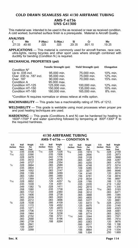
Sec. K page 114
coLD DRAWn SeAMLeSS ASi 4130 AiRFRAMe tubing
AMS-t-6736unS g41300
This material was intended to be used in the as received or near as received condition. A cold worked, burnished surface finish is a prerequisite. Material is Aircraft Quality.
AnALYSiS c Mn p (Max.) S (Max.) Si cr Mo .27/.33 .40/.60 .025 .025 .20/.35 .80/1.10 .15/.25
AppLicAtionS — This material is commonly used for aircraft frames, race cars, ultra-lights, racing bicycles and other sport uses where strength combined with ductility for bending (Condition N.) is required.
MecHAnicAL pRopeRtieS (psi)
tensile Strength (psi) Yield Strength (psi) elongation Condition N* Up to .035 incl. 95,000 min. 75,000 min. 10% min. Over .035 to .187 incl. 95,000 min. 75,000 min. 12% min. Over .187 90,000 min. 70,000 min. 15% min. Condition A 95.000 max. Condition HT-125 125,000 min. 100,000 min. 12% min. Condition HT-150 150,000 min. 135,000 min. 10% min. Condition HT-180 180,000 min. 165,000 min. 8% min.
*Condition N requires normalize or stress relieve at mills option.
MAcHinAbiLitY — This grade has a machinability rating of 78% of 1212.
WeLDAbiLitY — This grade is weldable using most processes when proper pre and post heating techniques are used.
HARDening — This grade (Conditions A and N) can be hardened by heating to 1600º-1700º F and water quenching followed by tempering at 800º-1300º F to the required hardness.
o.D. Wall Weight (inches) thick- per ness Foot 1/8 .035 .0336 3/16 .022 .0390 .028 .0478 .035 .0572 .049 .0727 1/4 .028 .0664 .035 .0804 .049 .1052 .058 .1189 .065 .1284 .072 .1369 5/16 .028 .0852 .035 .1039 .049 .1382 .058 .1580 .065 .1722 .075 .1906 .083 .2039 .095 .2212 3/8 .028 .1038 .032 .1172 .035 .1271 .049 .1706 .058 .1964 .065 .2152 .083 .2588 .090 .2739 .095 .2841 .109 .3097 .120 .3268
o.D. Wall Weight (inches) thick- per ness Foot 7/16 .028 .1226 .035 .1506 .042 .1776 .049 .2036 .058 .2354 .065 .2589 .072 .2814 .083 .3147 .088 .3289 .095 .3480 .120 .4075 .129 .4257 .134 .43511/2 .028 .1411 .035 .1738 .049 .2360 .058 .2738 .065 .3020 .083 .3696 .095 .4109 .109 .4552 .120 .4870 .131 .5163 .134 .5238 .156 .5731 .183 .6196 .188 .6264
o.D. Wall Weight (inches) thick- per ness Foot9/16 .035 .1974 .049 .2690 .058 .3128 .065 .3457 .083 .4255 .095 .4748 .109 .5285 .120 .5677 .134 .6140 .156 .6781 .219 .8034 5/8 .028 .1785 .035 .2205 .042 .2615 .049 .3014 .058 .3512 .065 .3888 .083 .4805 .095 .5377 .120 .6472 .125 .6675 .133 .6989 .156 .7814 .188 .8774 11/16 .049 .3344 .065 .4325 .083 .5363 .095 .6017 .120 .7279 .156 .8864 .188 1.004
o.D. Wall Weight (inches) thick- per ness Foot 3/4 .028 .2159 .035 .2673 .049 .3668 .058 .4287 .065 .4755 .072 .5214 .083 .5913 .095 .6646 .120 .8074 .134 .8816 .156 .9897 .188 1.128 .219 1.242 .250 1.335 13/16 .065 .5193 .083 .6471 .095 .7285 .109 .8195 .120 .8881 7/8 .028 .2533 .035 .3140 .049 .4323 .058 .5061 .065 .5623 .083 .7021 .095 .7914 .120 .9676 .156 1.198 .188 1.379 .219 1.534 .250 1.669
4130 AiRFRAMe tubingAMS-t-6736 — conDition n
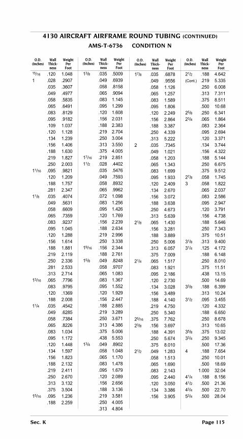
4130 AiRcRAFt AiRFRAMe RounD tubing (continueD)
AMS-t-6736 conDition n
o.D. Wall Weight (inches) thick- per ness Foot
15/16 .120 1.048 1 .028 .2907 .035 .3607 .049 .4977 .058 .5835 .065 .6491 .083 .8129 .095 .9182 .109 1.037 .120 1.128 .134 1.239 .156 1.406 .188 1.630 .219 1.827 .250 2.003 11/16 .095 .9821 .120 1.209 .188 1.757 .281 2.347 11/8 .035 .4074 .049 .5631 .058 .6609 .065 .7359 .083 .9237 .095 1.045 .120 1.288 .156 1.614 .188 1.881 .219 2.119 .250 2.336 .281 2.533 .313 2.714 13/16 .065 .7796 .083 .9795 .120 .1369 .188 2.008 11/4 .035 .4542 .049 .6285 .058 .7384 .065 .8226 .083 1.034 .095 1.172 .120 1.448 .134 1.597 .156 1.823 .188 2.132 .219 2.411 .250 2.670 .313 3.132 .375 3.504 15/16 .095 1.236 .188 2.259
o.D. Wall Weight (inches) thick- per ness Foot
13/8 .035 .5009 .049 .6939 .058 .8158 .065 .9094 .083 1.145 .095 1.299 .120 1.608 .156 2.031 .188 2.383 .219 2.704 .250 3.004 .313 3.550 .375 4.005 17/16 .219 2.851 11/2 .028 .4402 .035 .5476 .049 .7593 .058 .8932 .065 .9962 .072 1.098 .083 1.256 .095 1.426 .120 1.769 .156 2.239 .188 2.634 .219 2.996 .250 3.338 19/16 .156 2.344 .188 2.761 15/8 .049 .8248 .058 .9707 .065 1.083 .083 1.367 .095 1.552 .120 1.929 .156 2.447 .188 2.885 .219 3.289 .250 3.671 .313 4.386 .375 5.006 .438 5.553 13/4 .049 .8902 .058 1.048 .065 1.170 .083 1.478 .095 1.679 .120 2.089 .156 2.656 .188 3.136 .219 3.581 .250 4.005 .313 4.804
o.D. Wall Weight (inches) thick- per ness Foot
17/8 .035 .6878 .049 .9556 .058 1.126 .065 1.257 .083 1.589 .095 1.806 .120 2.249 .156 2.864 .188 3.387 .250 4.339 .313 5.222 2 .035 .7345 .049 1.021 .058 1.203 .065 1.343 .083 1.699 .095 1.933 .120 2.409 .134 2.670 .156 3.072 .188 3.638 .250 4.673 .313 5.639 21/8 .065 1.430 .156 3.281 .188 3.889 .250 5.006 .313 6.057 .375 7.009 21/4 .065 1.517 .083 1.921 .095 2.186 .120 2.730 .134 3.028 .156 3.489 .188 4.140 .219 4.750 .250 5.340 25/16 .375 7.762 23/8 .156 3.697 .188 4.391 .250 5.674 .375 8.010 21/2 .049 1.283 .058 1.513 .065 1.690 .083 2.143 .095 2.440 .120 3.050 .134 3.386 .156 3.905
o.D. Wall Weight (inches) thick- per ness Foot
21/2 .188 4.642 (Cont.) .219 5.335 .250 6.008 .313 7.311 .375 8.511 .500 10.68 25/8 .250 6.341 23/4 .065 1.864 .083 2.364 .095 2.694 .120 3.371 .134 3.744 .156 4.322 .188 5.144 .250 6.675 .375 9.512 27/8 .058 1.745 3 .058 1.822 .065 2.037 .083 2.586 .095 2.947 .120 3.791 .156 4.738 .188 5.646 .250 7.343 .375 10.51 31/8 .313 9.400 31/4 .125 4.172 .188 6.148 .250 8.010 .375 11.51 .438 13.15 .500 14.69 33/8 .188 6.399 .313 10.24 31/2 .095 3.455 .120 4.332 .188 6.650 .250 8.678 .313 10.65 35/8 .375 13.02 33/4 .250 9.345 .500 17.36 4 .188 7.654 .250 10.01 .500 18.69 1.000 32.04 41/4 .188 8.156 41/2 .500 21.36 43/4 .500 22.70 53/4 .500 28.04
Sec. K page 115

4130 SQuARe tubing
AMS-t-6736 conDition n
outside Wall Weight Dimensions thickness per Foot
3/8 x 3/8 .049 .2172 1/2 x 1/2 .035 .2213 .065 .3845 5/8 x 5/8 .035 .2808 .049 .3670 .058 .4472 .065 .4950 3/4 x 3/4 .035 .3403 .049 .4671 .058 .5454 .065 .6055
outside Wall Weight Dimensions thickness per Foot
7/8 x 7/8 .035 .3998 .049 .5504 1 x 1 .035 .4593 .049 .6337 .083 1.035 .125 1.488 11/4 x 11/4 .065 1.048 13/8 x 13/8 .058 1.039 11/2 x 11/2 .065 1.163 .125 2.338
4130 AiRcRAFt RectAnguLAR tubing
AMSt-6736 conDition n
outside Wall Weight Dimensions thickness per Foot
1 x 1/2 .049 .4671 .065 .6055 11/2 x 3/4 .049 .7170
outside Wall Weight Dimensions thickness per Foot
13/4 x 1 .065 1.158 2 x 11/2 .049 1.134
cDS 4130 StReAMLine tube
conDition n AMS-t-6736
SiZe WALL Wt/Ft 1.012 MAJOR X .428 MINOR X .035 WALL .2680#/FT 1.180 MAJOR X .500 MINOR X .035 WALL .3140#/FT 1.349 MAJOR X .571 MINOR X .049 WALL .3610#/FT 1.685 MAJOR X .714 MINOR X .049 WALL .6290#/FT 2.023 MAJOR X .857 MINOR X .049 WALL .7593#/FT 2.023 MAJOR X 1.429 MINOR X .049 WALL 1.2830#/FT
Sec. K page 116

HYDRAuLic Line tubing
HYDRAuLic Line tubing Hydraulic tubing has emerged as a special and separate tubular product as a
result of the importance of automation with increased use of hydraulic systems. Low carbon seamless condenser or mechanical tubing has been produced for years. Although it was satisfactory for many requirements, it failed to meet many of the main requisites for a steel hydraulic tubing.
A Joint Industries Council was formed and in 1949 published standards to be applied to this product. Provision was made for ductility to allow for consistent bending and flaring. Cleanliness standards were established to prevent contamination of the hydraulic fluid and damage to valves and cylinders. Uniformity of sizes was established to allow for use of standard fittings.
the J.i.c. Hydraulic Standards for industrial equipment, as well as more recent SAE Standards, recommend use of low carbon seamless tubing in all pressure ranges. Selection of the proper tubing depends on a number of factors such as pressure velocity and flow.
SiZeS AnD WeigHtS oF HYDRAuLic Line tubing 118-123 carbon Steel, Stainless Steel, Aluminum DeScRiptionS oF inDiViDuAL gRADeS Low carbon Steel pressure tubing 124 Aluminum Hydraulic Line tubing — 6061 125 Stainless Steel Hydraulic Line tubing type 304 126 type 321 127 type 347 127 type 21-6-9 128
Sec. K page 117

HYDRAuLic Line tubing (continueD)For product description and specifications
See Pages 118 - 123 of this section.
S=Seamless W=Welded and Drawn
outside Wall inside cARbon ALuMinuM Diameter thickness Diameter SteeL type type type type 6061-t6 (inches) (inches) (inches) 304 304 321 347 Steel Alum. 1/8 Ann. Ann. Ann. Hard
1/8 .008 .109 .0100 .0035 S .010 .105 .0123 .0043 S .012 .101 .0145 .0051 SW SW .016 .093 .0186 .0065 S SW S .020 .085 .0224 .0078 SW SW SW SW S .028 .069 .0290 .0101 SW S SW SW S .032 .061 .0318 .0112 S S .035 .055 .0336 .0115 SW S SW SW .042 .041 .0372 .0131 S .049 .027 .0398 .0140 S 5/32 .006 .144 .0963 .0034 S .008 .140 .0127 .0045 S .012 .132 .0185 .0065 S .016 .124 .0240 .0084 S .020 .116 .0291 .0102 S S .028 .100 .0384 .0135 S .035 .086 .0452 .0159 S .049 .058 .0560 .0197 S S 3/16 .005 .178 .0975 .0034 S .006 .176 .0116 .0041 S .008 .172 .0153 .0054 S .010 .168 .0190 .0067 S S .012 .164 .0225 .0079 S .016 .156 .0294 .0103 SW S SW W .020 .148 .0359 .0126 SW SW S S .022 .144 .0390 .0138 S S .025 .138 .0433 .0150 S .028 .131 .0478 .0168 SW SW SW SW S .035 .118 .0572 .0201 SW SW SW SW S S .042 .104 .0655 .0230 S S .049 .090 .0727 .0256 SW S S SW S .058 .072 .0805 .0283 S .065 .058 .0854 .0300 S S 7/32 .006 .207 .0136 .0048 S .010 .199 .0223 .0078 S .028 .163 .0570 .0200 S .035 .149 .0688 .0242 S .049 .121 .0888 .0312 SW 1/4 .006 .238 .0156 .0055 S .010 .230 .0256 .0090 S .012 .226 .0307 .0108 S S S .016 .218 .0400 .0140 SW S SW S .018 .214 .0446 .0156 S .020 .210 .0491 .0173 SW SW SW SW S .022 .206 .0536 .0189 S S .028 .194 .0664 .0235 SW SW SW SW SW S .035 .180 .0804 .0281 SW SW SW SW SW S .042 .166 .0933 .0328 S .049 .152 .1052 .0371 SW SW SW SW SW S .058 .134 .1189 .0419 S S S .065 .120 .1284 .0453 SW S S S S .078 .094 .1433 .0503 S .083 .084 .1480 .0523 SW S S
Sec. K page 118
Wt. per Ft.
StAinLeSS SteeL

HYDRAuLic Line tubing (continueD)For product description and specifications
See Pages 118 - 123 of this section.
S=Seamless W=Welded and Drawn
outside Wall inside cARbon ALuMinuM Diameter thickness Diameter SteeL type type type type 6061-t6 (inches) (inches) (inches) 304 304 321 347 Steel Alum. 1/8 Ann. Ann. Ann. Hard
9/32 .035 .211 .0920 .0323 S 5/16 .006 .301 .0196 .0069 S .008 .297 .0260 .0091 S .010 .293 .0323 .0113 S .012 .289 .0385 .0135 S .016 .281 .0507 .0178 SW S S W .020 .273 .0626 .0214 SW SW SW SW .025 .262 .0769 .0270 S .028 .257 .0852 .0300 SW SW SW SW S S .035 .243 .1039 .0366 SW SW SW SW SW S .042 .229 .1216 .0427 S .049 .215 .1382 .0487 SW S S SW S S .058 .197 .1580 .0561 SW S S .095 .122 .2212 .0777 SW 3/8 .008 .359 .0314 .0110 S .010 .355 .0390 .0137 S .012 .351 .0465 .0163 S .016 .343 .0613 .0215 S S SW SW .020 .335 .0758 .0267 SW S SW SW .022 .331 .0829 0.282 SW SW S .025 .325 .0935 .0328 S S .028 .319 .1038 .0366 SW SW SW SW S .035 .305 .1271 .0449 SW SW SW SW SW S .042 .293 .1494 .0525 S S S .049 .277 .1706 .0602 SW SW SW W S S .058 .259 .1964 .0694 SW W S S SW S .065 .245 .2152 .0755 SW SW SW S S .072 .231 .2230 .0818 S .083 .209 .2588 .0918 S S S S .095 .185 .2841 .0998 S S S .120 .135 .3268 .1148 S 7/16 .010 .418 .0457 .0160 W .012 .414 .0545 .0191 S .016 .406 .0720 .0253 S .020 .398 .0893 .0314 S .028 .381 .1226 .0431 S .035 .367 .1506 .0530 SW S S S S .049 .340 .2036 .0714 SW W SW SW S .058 .322 .2354 .0826 S .065 .307 .2589 .0908 SW S S S .083 .272 .3147 .1110 S .095 .247 .3480 .1224 S 1/2 .005 .490 .0264 .0092 S S .006 .488 .0317 .0111 S .010 .480 .0523 .0184 S .012 .476 .0625 .0220 S .016 .468 .0827 .0290 S SW SW .020 .460 .1025 .0356 S .025 .450 .1268 .0445 S .028 .444 .1411 .0496 SW SW SW SW S .032 .436 .1599 .0562 SW
Wt. per Ft.
StAinLeSS SteeL
Sec. K page 119

HYDRAuLic Line tubing (continueD)For product description and specifications
See Pages 118 - 123 of this section.
S=Seamless W=Welded and Drawn
outside Wall inside cARbon ALuMinuM Diameter thickness Diameter SteeL type type type type 6061-t6 (inches) (inches) (inches) 304 304 321 347 Steel Alum. 1/8 Ann. Ann. Ann. Hard
1/2 .035 .420 .1738 .0612 SW SW SW SW SW S (Cont.) .042 .416 .2054 .0721 S S S .049 .402 .2360 .0829 SW SW S SW SW S .058 .384 .2738 .0962 SW S S S .065 .370 .3020 .1061 SW SW SW SW S .083 .334 .3969 .1298 SW S S S .095 .310 .4109 .1443 S S S .109 .282 .4552 .1599 S .120 .260 .4870 .1710 S S S 9/16 .010 .543 .0590 .0207 S .016 .531 .0934 .0328 S .020 .523 .1159 .0407 S .028 .506 .1600 .0562 SW .042 .479 .2337 .0821 S .049 .464 .2690 .0948 SW S .065 .432 .3457 .1218 SW S .109 .344 .5285 .1856 S .120 .322 .5677 .1994 S 5/8 .010 .605 .0657 .0231 S .012 .601 .0786 .0276 S .016 .593 .1041 .0366 S SW .020 .585 .1292 .0454 SW SW SW SW S .028 .569 .1785 .0627 SW SW SW SW S .035 .555 .2205 .0775 SW SW SW SW SW .042 .541 .2615 .0918 SW SW S .049 .527 .3014 .1060 SW SW SW SW S S .058 .509 .3512 .1234 S SW S S S .065 .495 .3888 .1367 SW S SW S S .072 .471 .4252 .1493 .083 .459 .4805 .1693 SW S S S S .095 .435 .5377 .1888 S S .107 .411 .5919 .2079 S .120 .385 .6472 .2273 S .156 .312 .7814 .2744 S S S 11/16 .010 .668 .0724 .0254 S .028 .631 .1974 .0693 S .035 .617 .2441 .0857 S S .049 .589 .3344 .1174 SW S .065 .557 .4325 .1519 S 3/4 .010 .730 .0790 .0277 S S .012 .726 .0958 .0336 S .016 .718 .1254 .0440 S S SW S .020 .710 .1559 .0548 SW S SW S S .025 .700 .1936 .0680 S W W .028 .694 .2159 .0758 SW S SW S .035 .680 .2673 .0938 SW SW SW SW S S .042 .666 .3176 .1115 SW W S S .049 .652 .3668 .1288 SW SW SW SW S S .058 .643 .4287 .1506 SW S S S
Wt. per Ft.
StAinLeSS SteeL
Sec. K page 120

HYDRAuLic Line tubing (continueD)For product description and specifications
See Pages 118 - 123 of this section.
S=Seamless W=Welded and Drawn
outside Wall inside cARbon ALuMinuM Diameter thickness Diameter SteeL type type type type 6061-t6 (inches) (inches) (inches) 304 304 321 347 Steel Alum. 1/8 Ann. Ann. Ann. Hard
3/4 .065 .620 .4755 .1670 SW SW SW SW S S (Cont.) .072 .606 .5214 .1831 S .083 .584 .5913 .2077 SW S S S S S .095 .560 .6646 .2234 SW S S S S .109 .532 .7462 .2621 S .134 .482 .8816 .3096 S 13/16 .028 .757 .2347 .0824 S .035 .742 .2908 .1021 S .049 .714 .3998 .1404 S .065 .682 .5193 .1824 S S 7/8 .010 .855 .0924 .0325 S .016 .843 .1468 .0516 S .020 .835 .1826 .0641 S .028 .819 .2533 .0890 S S .035 .805 .3140 .1112 SW SW S S .042 .791 .3737 .1312 S .049 .777 .4323 .1530 SW S S S .058 .759 .5061 .1777 S S .065 .745 .5623 .1979 SW S S S .095 .685 .7914 .2795 SW S 15/16 .035 .867 .3375 .1185 S .065 .807 .6060 .2128 S 1 .010 .980 .1057 .0371 W S .012 .976 .1128 .0396 S .016 .968 .1681 .0590 SW S .020 .960 .2093 .0735 SW SW SW S .028 .944 .2907 .1021 S SW SW S .032 .936 .3308 .1162 S .035 .930 .3607 .1275 SW SW W SW S .042 .916 .4297 .1509 S S W S .049 .902 .4977 .1754 SW S SW SW W S .058 .884 .5835 .2060 S S S .065 .870 .6491 .2295 SW S S SW S S .083 .834 .8129 .2866 SW S S SW S S .095 .810 .9182 .3244 SW S S S .109 .782 1.037 .3642 SW .120 .760 1.128 .3978 SW S .125 .750 1.168 .4102 S S 11/16 .049 .964 .5306 .1863 S .065 .932 .6928 .2433 S 11/8 .012 1.101 .1426 .0501 W .020 1.085 .2360 .0829 SW .035 1.055 .4074 .1438 S S .049 1.027 .5631 .1989 S S S .058 1.009 .6609 .2321 S S .065 .995 .7359 .2601 S S .083 .959 .9237 .3264 S .095 .935 1.045 .3670 SW S
Wt. per Ft.
StAinLeSS SteeL
Sec. K page 121

HYDRAuLic Line tubing (continueD)For product description and specifications
See Pages 118 - 123 of this section.
S=Seamless W=Welded and Drawn
outside Wall inside cARbon ALuMinuM Diameter thickness Diameter SteeL type type type type 6061-t6 (inches) (inches) (inches) 304 304 321 347 Steel Alum. 1/8 Ann. Ann. Ann. Hard
11/4 .012 1.226 .1587 .0557 S .016 1.218 .2109 .0741 SW S .020 1.210 .2627 .0923 SW S .022 1.206 .2885 .1013 S .025 1.200 .3271 .1149 S .028 1.194 .3654 .1283 SW S SW S S .035 1.180 .4542 .1601 SW SW SW S S .042 1.166 .5419 .1903 S .049 1.152 .6285 .2213 S SW SW S S .058 1.134 .7384 .2601 S .065 1.120 .8266 .2907 SW S S SW S S .083 1.084 1.034 .3652 S S .095 1.060 1.172 .4131 SW S S .109 1.032 1.328 .4682 SW S .120 1.010 1.448 .5100 SW 13/8 .020 1.335 .2894 .1016 S .028 1.319 .4028 .1415 S .035 1.305 .5009 .1759 S .049 1.277 .6939 .2448 S .058 1.259 .8158 .2865 S S .065 1.245 .9094 .3213 S S 11/2 .010 1.480 .1591 .0559 S .012 1.476 .1907 .0670 S .016 1.468 .2536 .0891 S S .020 1.460 .3161 .1110 SW S .022 1.456 .3473 .1220 S .025 1.450 .3938 .1383 S .028 1.444 .4402 .1546 S S SW S S .032 1.436 .5018 .1762 S .035 1.430 .5476 .1928 S SW SW S S .049 1.402 .7593 .2683 SW S SW S S .058 1.384 .8932 .3137 S .065 1.370 .9962 .3519 SW S S S S S .083 1.334 1.256 .4437 SW S .095 1.310 1.426 .5029 SW S S .120 1.260 1.769 .6222 SW S S S .250 1.000 3.338 1.173 S 15/8 .020 1.585 .3428 .1204 S .028 1.569 .4776 .1677 S .035 1.555 .5943 .2101 SW .049 1.527 .8248 .2907 S S .058 1.509 .9707 .3409 S .065 1.495 1.083 .3825 S 13/4 .012 1.726 .2227 .0782 W .016 1.718 .2963 .0141 S .020 1.710 .3695 .1298 SW .028 1.694 .5149 .1808 S S .035 1.680 .6411 .2264 SW SW S .049 1.652 .8902 .3142 S S .058 1.634 1.048 .3703 S .065 1.620 1.170 .4131 S .083 1.584 1.478 .5202 S .156 1.438 2.656 .9384 S .203 1.344 3.354 1.159 SW
Wt. per Ft.
StAinLeSS SteeL
Sec. K page 122

HYDRAuLic Line tubing (continueD)For product description and specifications
See Pages 118 - 123 of this section.
S=Seamless W=Welded and Drawn
outside Wall inside Diameter thickness Diameter type type type type (inches) (inches) (inches) 304 304 321 347 Steel Alum. 1/8 Ann. Ann. Ann. Hard
17/8 .028 1.819 .5523 .1940 S .049 1.777 .9556 .3356 S S .056 1.759 1.126 .3954 S .065 1.745 1.257 .4415 S .095 1.685 1.806 .6343 S 2 .016 1.968 .3390 .1191 S .020 1.960 .4229 .1485 SW S .025 1.950 .5273 .1852 SW .028 1.944 .5897 .2071 SW .035 1.930 .7345 .2591 S SW SW W .049 1.902 1.021 .3601 S S SW S .065 1.870 1.343 .4743 S S S S .083 1.834 1.699 .6018 SW .095 1.810 1.933 .6834 S S S .120 1.760 2.409 .8466 S .250 1.500 4.673 1.652 S 21/8 .028 2.069 .6271 .2202 S .035 2.055 .7812 .2744 S .049 2.027 1.086 .3814 S .065 1.995 1.430 .5022 S 21/4 .020 2.210 .4763 .1673 S S .028 2.194 .6645 .2334 S S .035 2.180 .8280 .2917 S S .049 2.152 1.152 .4060 S S .065 2.120 1.517 .5328 S .083 2.084 1.921 .6746 S 23/8 .049 2.277 1.271 .4274 S .065 2.245 1.604 .5633 S 21/2 .020 2.460 .5297 .1860 S .022 2.456 .5822 .2045 S .028 2.444 .7392 .2596 S S .035 2.430 .9214 .3245 S S SW S .049 2.402 1.283 .4506 S S S .065 2.370 1.690 .5916 SW S S 25/8 .035 2.805 .9681 .3400 S .049 2.527 1.348 .4784 S 23/4 .016 2.718 .4672 .1641 S S .065 2.620 1.864 .6528 SW S .120 2.510 3.371 1.193 S 3 .010 2.976 1.057 .3712 W .035 2.930 1.108 .3891 S .049 2.902 1.544 .5423 S .065 2.870 2.037 .7140 W .095 2.810 2.947 1.040 W
Wt. per Ft. StAinLeSS SteeL
Sec. K page 123

LoW cARbon SteeL pReSSuRe tubing
SeAMLeSS SAe J524 AStM A 179(AVg. WALL)WeLDeD AnD DRAWn SAe J525 AStM A 214(AVg. WALL)
This tubing is especially processed for the transmission of fluids under pressure. It may also serve as a heat exchanger since it is produced for maximum ductility to allow for bending and flaring. The inside diameter is clean to prevent contamination of fluids.
AnALYSiS c Mn p (Max.) S (Max.) A179 .06-.08 .27-.63 .035 .035 A214 .18 max .27-.63 .035 .035 J524 .18 max .30-.60 .040 .050 J525 .18 max .30-.60 .040 .050
MecHAnicAL pRopeRtieS—The following minimum mechanical properties apply:
tensile Yield brindell Strength Strength elongation Hardness Minimum (psi) Minimum (psi) A179 RB 72 max A214 RB 72 max J524 45,000 25,000 35% RB 65 max J525 45,000 25,000 35% RB 65 max
AppLicAtionS — It may be used to convey hydraulic fluids to pressures up to 300 psi.
LoW cARbon pReSSuRe tube — Heat Exchanger, Hydraulic Line
Heat exchanger tolerance oD Wall Specification Size oD plus Minus plus Minus range (in) ASTM A179 Under 1.000 .004” .004” 20% 0% ASME SA-179 1.000 - 1.500 .006” .006” 20% 0% Cold Drawn Seamless 1.501 - 1.999 .008” .008” 22% 0% Heat Exchanger Tube 2.000 - 2.499 .010” .010” 22% 0% Minimum Wall 2.000 — 2.499 .010” .010” 22% 0% 2.500 — 2.999 .012” .012” 22% 0% 3.000 — 4.000 .015” .015” 22% 0% ASTM A214 Under 1.000 .004” .004” 18% 0% ASME SA-214 1.000 - 1.500 .006” .006” 18% 0% ERW Welded 1.501 - 1.999 .008” .008” 18% 0% Heat Exchanger Tube 2.000 — 2.499 .010” .010” 18% 0% Minimum Wall 2.500 — 2.999 .012” .012” 18% 0% 3.000 — 4.000 .015” .015” 18% 0%
Also available in average wall ± 10% tolerance.Tubes over 2” OD x .135” wall, ID weld flash controlled .010” max. height.Tubes 2” OD x .135” wall and under, ID weld flash controlled .006” max. height.
Hydraulic line tolerance oD Wall Specification Size oD plus Minus plus Minus range (in) Up to .375 .003” .003” 15% 15% SAE-J524 .0376 - .500 .003” .003” 10% 10% .501 — 1.500 .005” .005” 10% 10% Cold Drawn Seamless 1.500 — 2.500 .010” .010” 10% 10% JIC Hydraulic Line ASTM A179 2.501-3.000 .010” .010” 10% 10% (Avg. wall) 3.001 — 3.500 .010” .010” 10% 10% Up to .375 .002” .002” 15% 15% SAE_J525 .0376 - .625 .0025” .0025” 10% 10% Welded and Drawn .625 — 2.000 .003” .003” 10% 10% HC Hydraulic Line 2.001 — 2.500 .004” .004” 10% 10% ASTM A214 2.501 — 3.00 .005” .005” 10% 10% (Avg. Wall) 3.001 — 4.000 .006” .006” 10% 10%
Sec. K page 124

SeAMLeSS 6061 ALuMinuM ALLoY coLD DRAWn
AiRcRAFt HYDRAuLic QuALitY
AMS-t-7081 AMS 4081(t4) AMS 4083(t6)
This material is intended for use as hydraulic lines with relatively low pressure and severe flares.
AnALYSiS cu Si Fe (Max.) Mn (Max.) Mg Zn (Max.) cr ti (Max.) Al
.15/.40 .40/.80 .70 .15 .80/1.2 .25 .04/.35 .15 Rem.
MecHAnicAL pRopeRtieS
tensile Yield elongation
Walls Strength Strength elongation
Minimum (psi) Minimum (psi)
t4 .025 thru .049 30,000 16,000 16% min. (Solution .050 thru .259 30,000 16,000 18% min. Treated) t6 .025 thru .049 42,000 35,000 10% min. (Solution .050 thru .259 42,000 35,000 12% min. Treated and Artificially Aged)
AppLicAtion — Low pressure aircraft hydraulic lines with pressures calculated using the values shown above. Material is non destructive electric tested, pressure tested and double flare tested.
HARDening — Material is supplied in the treated condition as shown above.
WeLDing — This material is intended to be joined by flared fittings.
Sec. K page 125

tYpe 304 StAinLeSS HYDRAuLic Line tubing
SeAMLeSS — WeLDeD AnD DRAWn
Annealed: 1/8 Hard: MiL-t-8504 AMS-t-6845 AMS 5560 (Seamless) AMS 5566 AMS 5565 (Welded & Drawn)
Type 304 is the low carbon “18-8” chromium-nickel stainless steel in seamless or welded and drawn hydraulic tubing. It is produced by the electric furnace process conforming to the best practices for high quality aircraft material. Both OD and ID are free from scale, pickling, residues, heat discoloration, and severe surface defects. Slight surface imperfections such as handling marks, straightening marks, shallow seams, and the like are not to be considered as injurious provided these imperfections are removed within the diameter and wall thickness tolerances. This product is free from grease, metallic flakes, or particles which will tend to con-taminate the hydraulic fluid.
AnALYSiS c (Max.) Mn (Max.) Si (Max.) p (Max.) S (Max.) cr ni Mo (Max.) cu (Max.)
.08 2.00 .75 .030 .030 18.00/20.00 8.00/11.00 .50 .50
AppLicAtionS — It is intended for use in high pressure hydraulic and pneumatic systems up to 3000 psi pressure in which a corrosion resistant material is required. It is not suitable in those applications assembled by welding or brazing nor for those applications in which temperature is higher than 800ºF because of lessening in the resistance to corrosion. Where dual ductility and lower strength are required, tubing should meet AMS-T-6845, but heavier wall thicknesses must be used.
MecHAnicAL pRopeRtieS —
elongation
tensile Yield in 2” minimum
Strength (psi) Strength (psi) Strip tube
Annealed 75,000/100,000 30,000 min. 35% 40%
1/8 Hard: 95,000/130.000 60,000/90,000 --- 25% 3/16 OD and less, Wall .016 and Over 1/4 OD 105,000/140,000 75,000/110,000 -- 20% and over
StocK SiZeSRefer to listing on Pages 118-123 of this section, where availability of this product is indicated in the TYPE 304 1/8 Hard and TYPE 304 Annealed columns by the symbols S (for seamless) and W (for welded and drawn).
Sec. K page 126

tYpeS 321 & 347 StAinLeSS HYDRAuLic Line tubing
SeAMLeSS — WeLDeD AnD DRAWn
MiL-t-8808 AMS 5556 (tYpe 347) AMS 5557 (tYpe 321) AMS-t-8506 Types 321 and 347 are the stabilized “18-8” chromium-nickel stainless steels. They are designed to overcome susceptibility to carbide precipitation with resulting intergranular corrosion that may occur in the austenite stainless steels during exposure to temperatures of 800º to 1500º F.
Type 321 is stabilized with the addition of Titanium and 347 is stabilized with the addition of Columbium or Columbium-Tantalum.
Both grades are manufactured by the electric furnace process conforming to the best practices for high quality aircraft material. Both outside and inside surfaces are free from scale, pickling residues, heat discoloration, carburization, or metallic particles which would serve to contaminate the hydraulic fluid. Slight surface imperfections such as handling marks, shallow pits or seams are not considered detrimental so long as they are removable within the specific tolerances for diameter and wall thickness.
AnALYSiS c (Max.) Mn (Max.) p (Max.) S Si cr ni cu (Max.) Mo (Max.) n
(Max.)
321 .08 2.00 .040 .030 .40/1.00 17.00/20.00 9.00/12.00 .50 .50 .10titanium 6x(c+n)/.70
347 .08 2.00 .040 .030 .50/1.00 17.00/19.00 9.00/13.00 .50 .50 —columbium or cb+ta 10xc/1.00
AppLicAtionS — This tubing is used in high pressure hydraulic and pneumatic systems where corrosion and heat resistance are required. It is particularly adapt-able to parts and assemblies that are welded or brazed during fabrication. It offers oxidation resistance up to approximately 1500ºF, but should be used at that tempera-ture only when stresses are low.
MecHAnicAL pRopeRtieS — tensile Yield elongation
oD Wall thickness Strength Strength 2” Min.
(psi) (psi) Strip tube
.188 and under .016 and under 75,000/120,000 30,000 Min. -- 33% Over .016 75,000/105,000 30,000 Min. -- 35% Over .188 to .500 010 and under 75,000/115,000 30,000 Min. 30% 35% .010 and over 75,000/115,000 30,000 Min. 30% 35% Over .500 Over .010 75,000/105,000 30,000 Min. 30% 35%
StocK SiZeS Refer to listing on Pages 118-123 of this section, where availability of this product is indicated in the TYPE 321 and TYPE 347 columns by the symbols S (for seamless) and W (for welded and drawn).
Sec. K page 127

AiRcRAFt HYDRAuLic Line QuALitY tubing
WeLDeD AnD DRAWn 21-6-9unS S21900
AMS 5561 cLASS 1, cLASS 2bMS 7-185
This grade is provided in the 1/2 hard condition only for use in high pressure aircraft hydraulic lines. Material is welded and redrawn to size.
AnALYSiS c (Max.) Mn Si (Max.) p (Max.) S (Max.) cr ni n Mo (Max.) cu (Max.) .04 8.0/10.0 1.00 .030 .030 19.0/21.5 5.5/7.5 .15/.40 .75 .75
MecHAnicAL pRopeRtieS142,000 psi (979 Mpa) - 162,000 psi (1117 Mpa) Tensile120,000 psi (827 Mpa) min. Yield20% min. Elongation
uLtRASonic teSt Class 1 .125” length Ultrasonic CalibrationClass 2 .060” length Ultrasonic CalibrationBMS 7-185 Notch same as Class 2Class 3 Not Ultrasonic Tested
toLeRAnceS — Reference AMS 2243
WeLDing — Material is intended to be joined by flared fittings.
oD Fraction oD Wall iD Reference Wt/Ft only 3/16” 0.187 0.020 0.147 0.036 1/4” 0.250 0.016 0.218 0.040 0.250 0.020 0.210 0.049 0.250 0.022 0.206 0.054 0.250 0.028 0.194 0.066 0.250 0.035 0.180 0.080 5/16” 0.313 0.016 0.281 0.051 0.313 0.020 0.273 0.063 0.313 0.035 0.243 0.104 0.375 0.016 0.343 0.061 3/8” 0.375 0.020 0.335 0.076 0.375 0.028 0.319 0.104 0.375 0.032 0.311 0.117 0.375 0.035 0.305 0.127 0.375 0.049 0.277 0.171 1/2” 0.500 0.016 0.468 0.083 0.500 0.020 0.460 0.103 0.500 0.026 0.448 0.132 0.500 0.035 0.430 0.174 0.500 0.049 0.402 0.236 0.500 0.065 0.370 0.302 5/8” 0.625 0.016 0.593 0.104 0.625 0.020 0.585 0.129 0.625 0.033 0.559 0.209 0.625 0.054 0.517 0.329 3/4” 0.750 0.016 0.718 0.125 0.750 0.028 0.694 0.216 0.750 0.035 0.680 0.267 0.750 0.049 0.652 0.367 0.750 0.065 0.620 0.476 0.750 0.083 0.584 0.591 1” 1.000 0.028 0.944 0.291 1.000 0.049 0.902 0.498 1.000 0.052 0.896 0.526 1.000 0.095 0.810 0.918 11/4” 1.250 0.024 1.202 0.314 1.250 0.032 1.186 0.416 1.250 0.049 1.152 0.629 1.250 0.058 1.134 0.738 11/2” 1.500 0.049 1.402 0.759 13/4” 1.750 0.049 1.652 0.890
Sec. K page 128

Sec. K page 129
titAniuM tubing
cold Finished Seamless 3 A A1-21/2 V Alloy 130
cold Finished Seamless commercially pure 131
Welded comercially pure Ducting 132-133
bulging and bursting pressures 134-136

Sec. K page 130
coLD FiniSHeD SeAMLeSS 3 A1-2-1/2V titAniuM ALLoY
AiRcRAFt HYDRAuLic Line QuALitY
AMS 4945AMS 4944MMS1205DMS 2241bMS 7-234
SiMiLAR to unS R56320
AnALYSiS AL V Fe o c n H Y Res ti (Max.) (Max.) (Max.) (Max.) (Max.) (Max.) (Max.)
2.50/3.50 2.0/3.0 .30 .12 .05 .02 .015 .005 .50 Remainder
MecHAnicAL pRopeRtieS AMS 4944 up to .016” Wall include: tensile Yield elongation (psi) (psi) 125,000 Min 105,000 Min. 8% Min.
Over .016” Wall:
tensile Yield elongation (psi) (psi) 125,000 Min. 105,000 Min. 10% Min.
AMS 4945 Same tensile Yield elongation (psi) (psi) MMS 1205 CWSR 70 85,000/102,000 (psi) 70,000 (psi) Min. 15% Min. MMS 1205 CWSR 70 100,000/126,000 (psi) 95,000 (psi) Min. 13% Min. MMS 1205 CWSR 105 125,000/142,000 (psi) 105,000 (psi) Min. 14% Min.* BMS 7-234 Grade I Same as AMS 4945 Except Maximum Tensile 145 psi BMS 7-234 Grade II 100,000/133,000 (psi) 95,000 (psi) Min. 13% Min.
*.250” OD 10% Min
pReSSuRe teSt — This material will receive pressure testing on a periodic basis.
AppLicAtion — These materials are intended for use on high pressure aircraft hydraulic systems with pressures calculated from values shown above.
WeLDing — These materials are intended to be joined with flared fittings.

coLD FiniSHeD SeAMLeSS coMMeRciALLY puRe titAniuM
AiRcRAFt HYDRAuLic Line QuALitY
DMS 1897
AnALYSiS Fe o c n H Res ti (Max.) (Max.) (Max.) (Max.) (Max.) (Max.)
.30 .25 .10 .03 .015 .30 Remainder
MecHAnicAL pRopeRtieS Cold Worked and Stress Relieved tensile Yield elongation (psi) (psi) 80,000 Min. 65,000 Min. 10% Min.
toLeRAnceS .095OD - .624OD + .003/-.000 Wall +/-10% -5% .625OD - .999OD + .004/-.000 Wall +/-10% -5% 1.00)D-1.499OD + .005/-.000 Wall +/-10% -5%
HYDRoStAtic teSt — 2 samples from each lot shall be subjected to internal pressure equal to two times internal pressure calculated or 15,000 psi whichever is less.
uLtRASonic teSt — 100% ultrasonic tested with notch length: up to .045” Wall 0.46-.060” Wall .060 .125
AppLicAtion — This material is intended for a low pressure hydraulic system.
WeLDing — This material is intended to be joined by flared fittings.
Sec. K page 131

WeLDeD coMMeRciALLY puRe titAniuM Ducting
DMS 1872 DMS 1878
This material is intended for thin wall tubing ducts for aircraft parts.
AnALYSiS c (Max.) H (Max.) other elements (Max.) ti 0.020 0.015 0.6 Remainder
Quality Level — Material produced under these specification shall be melted under a vacuum.
MecHAnicAL pRopeRtieS — (taken from raw materials)
tensile Yield elongation
(psi) (psi)
DMS 1872 50,000 Min. 40,000/60,000 24% DMS 1878 65,000 Min. 55,000/80,000 20%
SpeciAL teSt ReQuiReMent — Material produced to these specifications shall be 100% X-ray inspected in the weld area. X-ray films shall accompany ship-ment.
WeLD beAD — This material may be furnished with weld bead cold reduced. In no case shall the weld height exceed .0025” and the sum of outside and inside beads shall not exceed .004”.
Sec. K page 132

coml pure 3AL-21/2V
oD WALL iD Wt./Ft. Wt./Ft. 0.250 0.016 0.218 0.0230 0.0229 0.250 0.020 0.210 0.0283 0.0281 0.250 0.022 0.206 0.0308 0.0306 0.250 0.028 0.194 0.0382 0.0380 0.250 0.035 0.180 0.0462 0.0460 0.275 0.020 0.235 0.0313 0.0311 0.312 0.020 0.272 0.0359 0.0357 0.312 0.035 0.242 0.0596 0.0592 0.375 0.019 0.337 0.0416 0.0413 0.375 0.020 0.335 0.0436 0.0434 0.375 0.022 0.331 0.0477 0.0474 0.375 0.028 0.319 0.0597 0.0593 0.375 0.032 0.311 0.0674 0.0670 0.375 0.035 0.305 0.0731 0.0727 0.375 0.042 0.291 0.0859 0.0854 0.500 0.020 0.460 0.0590 0.0586 0.500 0.026 0.448 0.0757 0.0753 0.500 0.028 0.444 0.0812 0.0807 0.500 0.035 0.430 0.1000 0.0994 0.500 0.056 0.388 0.1528 0.1519 0.500 0.065 0.370 0.1737 0.1727 0.625 0.020 0.585 0.0744 0.0739 0.625 0.023 0.579 0.0851 0.0846 0.625 0.027 0.571 0.0992 0.0986 0.625 0.032 0.561 0.1166 0.1159 0.625 0.044 0.537 0.1571 0.1561 0.625 0.071 0.483 0.2417 0.2402 0.750 0.020 0.710 0.0897 0.0892 0.750 0.027 0.696 0.1200 0.1192 0.750 0.035 0.680 0.1538 0.1528 0.750 0.030 0.690 0.1327 0.1319 0.750 0.052 0.646 0.2230 0.2217 0.875 0.061 0.753 0.3051 0.3033 1.000 0.028 0.944 0.1672 0.1662 1.000 0.035 0.930 0.2075 0.2063 1.000 0.036 0.928 0.2133 0.2119 1.000 0.051 0.898 0.2974 0.2956 1.250 0.035 1.180 0.2613 0.2597 1.250 0.045 1.160 0.3332 0.3312 1.250 0.065 1.120 0.4733 0.4704 1.500 0.020 1.460 0.1819 0.1808 1.500 0.025 1.450 0.226 0.2252 1.500 0.028 1.444 0.2533 0.2517 1.500 0.035 1.430 0.3151 0.3132 1.500 0.049 1.402 0.4369 0.4342 1.500 0.054 1.392 0.4798 0.4769 2.500 0.035 2.430 0.5302 0.5269 3.000 0.020 2.960 0.3662 0.3640 3.000 0.025 2.950 0.4570 0.4542 3.000 0.035 2.930 0.6377 0.6338 3.000 0.040 2.920 0.7276 0.7231 3.000 0.049 2.902 0.8886 0.8831 3.000 0.065 2.870 1.1723 1.1651 3.500 0.035 3.430 0.7452 0.7407 3.500 0.040 3.420 0.8505 0.8453 4.000 0.032 3.936 0.7803 0.7755 4.000 0.035 3.930 0.8528 0.8475 4.000 0.040 3.920 0.9734 0.9674 4.000 0.049 3.902 1.1897 1.1824 4.500 0.040 4.420 1.0963 1.0895 4.500 0.050 4.400 1.3673 1.3589 4.500 0.065 4.370 1.7714 1.7606 4.750 0.040 4.670 1.1577 1.1506 5.000 0.025 4.950 0.7643 0.7596 5.000 0.028 4.944 0.8555 0.8502 5.000 0.032 4.936 0.9769 0.9709 5.000 0.035 4.930 1.0678 1.0613 5.000 0.040 4.920 1.2192 1.2117 5.000 0.050 4.900 1.5209 1.5116 5.000 0.065 4.870 1.9712 1.9591 6.000 0.050 5.900 1.8281 1.8169
Sec. K page 133

buLging AnD buRSting pReSSuReS
bARLoW’S FoRMuLA
There are several formulas for calculating the bursting pressures of tubes. The most widely used is Barlow’s formula, which is as follows: p= 2 St D
where P = Bursting pressure in psi S = Tensile strength of tube material, or fiber stress in the wall t = Wall Thickness in inches D = Outside diameter in inches
EXAMPLE:To find bursting pressure of a tube 4” OD x .250” wall, with tensile strength of 80,000 psi:
P= 2 X 80,000 X .250 = 40,000 = 10,000 bursting pressure 4 4
The formula may be rearranged to determine necessary dimensions or tensile strength to produce a desired bursting pressure, as follows:
t = DP D = 2St S = DP 2S P 2t
EXAMPLES: To find wall thickness necessary to withstand a pressure of 10,000 psi in a 4” OD tube with 80,000 psi tensile strength:
t = 4 X 10,000 = 40,000 = .250” wall thickness 2 X 80,000 160,000
To find necessary OD to withstand a pressure of 10,000 psi in a tube with .250” wall and tensile strength of 80,000 psi:
D = 2 X 80,000 X .250 = 40,000 = 4” outside diameter 10,000 10,000
To find the tensile strength of material necessary to withstand a pressure of 10,000 psi in a tube 4” OD x .250” wall:
S = 4 X 10,000 = 40,000 = 80,000 psi tensile strength 2 X .250 .500
Actual bursting tests have shown the formula to be conservative, but consideration should be given to allowance for safety factors based on the particular design.
Sec. K page 134

Wal
l t
hick
ness
(in
ches
)
bW
g e
qui
vale
nt
Frac
tion
al e
qui
vale
nt
Out
side
.0
20
.028
.0
35
.049
.0
65
.095
.1
20
.156
.1
87
.210
.2
50
.313
.3
75
.500
.6
25
.750
.8
75
1.00
Di
amet
er
25
22
20
18
16
13
11
5 /32”
3 /1
6”
7 /32”
1 /4
” 5 /1
6”
3 /8”
1 /2”
5 /8”
3 /4”
7/8”
1”
(in)
1 /8
32
00
5200
56
00
7840
3 /1
6 21
33
2987
39
33
5227
1 /4
16
00
2240
28
00
3920
52
00
7600
5 /1
6 12
80
1798
22
40
3136
41
60
6100
3 /8
10
67
1493
18
67
2613
34
67
5067
64
00
1 /2
80
0 11
20
1400
19
60
2600
38
00
4800
62
40
7480
5 /8
640
869
1120
15
68
2080
30
40
3840
49
92
5984
70
08
3 /4
533
747
933
1307
17
33
2533
32
00
4160
49
87
5840
66
67
7 /8
45
7 64
0 80
0 11
20
1486
21
71
2743
35
66
4274
50
06
5714
71
54
1 40
0 56
0 70
0 98
0 13
00
1900
24
00
3120
37
40
4380
50
00
6260
75
00
11
/8 35
5 49
8 62
2 87
1 11
56
1685
21
33
2773
33
24
3893
44
44
5564
66
67
11
/4 32
0 44
8 56
0 78
4 10
40
1520
19
20
2496
29
92
3504
40
00
5008
60
00
8000
13
/8 29
0 40
7 50
9 71
3 94
5 13
82
1745
22
69
2720
31
85
3636
45
53
5455
72
73
11/2
267
393
467
653
867
1267
16
00
2080
24
93
2920
33
33
4173
50
00
6667
83
33
13
/4 29
9 31
8 40
0 56
0 74
3 10
86
1371
17
83
2137
25
03
2857
35
77
4286
57
14
7143
2 20
0 28
0 35
0 49
0 65
0 95
0 12
00
1560
18
70
2190
25
00
3130
37
50
5000
62
50
7500
21
/4 17
8 25
0 31
1 43
6 57
8 84
4 10
67
1387
16
62
1947
22
22
2782
33
33
4444
55
56
6667
21
/2
28
0 39
2 52
0 76
0 96
0 12
48
1496
17
52
2000
25
04
3000
40
00
5000
60
00
7000
23/4
255
356
473
691
873
1135
13
60
1593
18
18
2276
27
27
3636
45
45
5455
63
64
7273
3
32
7 43
3 63
3 80
0 10
40
1247
14
60
1667
20
87
2500
33
33
4167
50
00
5833
66
67
31/4
30
2 40
0 58
5 73
8 96
0 11
51
1348
15
38
1926
23
08
3077
38
46
4615
53
85
6154
31
/2
280
371
543
686
891
1069
12
51
1429
17
89
2413
28
57
3571
42
86
5000
57
14
33/4
26
1 34
7 50
7 64
0 83
2 99
7 11
68
1333
16
69
2000
26
67
3333
40
00
4667
53
33
4
245
325
475
600
780
935
1095
12
50
1565
18
75
2500
31
25
3750
43
75
5000
41
/4
30
6 44
7 56
5 73
4 88
0 10
31
1176
14
73
1765
23
53
2941
35
29
4118
47
06
41/2
289
412
533
693
831
973
1111
13
91
1667
22
22
2778
33
33
3889
44
44
43/4
274
400
505
657
787
922
1053
13
18
1579
21
05
2632
31
58
3684
42
11
5
26
0 38
0 48
0 62
4 74
8 87
6 10
00
1252
15
00
2000
25
00
3000
35
00
4000
51
/2
345
436
567
680
796
909
1138
13
64
1818
22
73
2727
31
82
3636
6
31
7 40
0 52
0 62
3 73
0 83
3 10
43
1250
16
67
2083
25
00
2917
33
33
61/2
369
480
575
674
769
963
1154
15
38
1923
23
08
2692
30
07
7
446
534
626
714
894
1071
14
29
1789
21
43
2500
28
57
71/2
41
6 49
9 58
4 66
7 83
5 10
00
1333
16
67
2000
23
33
2667
8
468
548
625
783
938
1250
15
63
1875
21
88
2500
81
/2
515
588
736
882
1176
14
71
1765
20
59
2353
9
556
696
833
1111
13
89
1667
19
44
2222
91
/2
52
6 65
9 78
9 10
53
1316
15
79
1842
21
05
10
500
626
750
1000
12
50
1500
17
50
2000
10
1 /2
473
596
714
952
1190
14
29
1667
19
05
The
abov
e ta
ble
is b
ased
on
the
best
kno
wn
and
mos
t wid
ely
used
form
ula
for c
alcu
latin
g th
e bu
rstin
g pr
ess
of tu
bes,
na
mel
y, B
arlo
w’s
:
P =
2S
t
D
whe
re
P =
B
urst
ing
pres
sure
in p
si
S =
Te
nsile
stre
ngth
of t
ube
mat
eria
ls o
r fib
er s
tress
in
the
wal
l
T =
W
all t
hick
ness
in in
ches
D
=
Out
side
dia
met
er in
inch
es
The
tabl
e (S
=10,
000)
affo
rd e
asy
calc
ulat
ions
with
app
ropr
iate
mul
tiplie
rs s
how
n be
low
. Fo
r the
oret
ical
bu
rstin
g pr
essu
res,
use
tens
ile v
alue
s. F
or th
eore
tical
bul
ging
pre
ssur
es, u
se y
ield
val
ues.
Wor
king
pr
essu
res
will
var
y de
pend
ing
upon
saf
ety
fact
ors
requ
ired
for e
nviro
nmen
tal c
ondi
tions
invo
lved
, as
de
term
ined
by
your
des
ign
engi
neer
and
app
ropr
iate
cod
es.
Mat
eria
l Te
nsile
(mul
tiplie
r)
Yie
ld (m
ultip
lier)
6061
-T6
Alu
min
um
42,0
00 p
si (x
4.2
) 35
,000
psi
(x 3
.5)
Ann
eale
d Lo
w C
arbo
n S
teel
55
,000
psi
(x 5
.5)
25,0
00 p
si (x
2.5
)A
nnea
led
18-8
Sta
inle
ss
75,0
00 p
si (x
7.5
) 30
,000
psi
(x 3
.0)
1/8
Har
d 18
-8 S
tain
less
10
5,00
0 ps
i (x1
0.5)
75
,000
psi
(x 7
.5)
Col
d D
r. 21
-6-9
Sta
inle
ss
142,
000
psi (
x 14
.2)
120,
000
psi (
x12.
0)
Sec. K page 135

tHeoReticAL buRSting AnD buLging pReSSuReS FoR pipeStainless Steel (AStM A312)
nominal Schedule outside Wall inside internal external size (in) number Diameter thickness Diameter pressure pressure (in) (in) (in) (psi) (psi) bursting collapsing 1/8 10 0.405 0.049 0.307 18,150 7,468 40 0.405 0.068 0.269 25,185 10,761 80 0.405 0.095 0.215 35,185 15,441 1/4 10 0.540 0.065 0.541 18,055 7,425 40 0.540 0.088 0.364 24,444 10,415 80 0.540 0.119 0.302 33,055 14,445 3/8 10 0.678 0.065 0.545 14,380 5,705 40 0.678 0.091 0.493 20,132 8,397 80 0.678 0.126 0.423 27,878 12,021 1/2 5 0.840 0.065 0.710 11,607 4,407 10 0.840 0.083 0.674 14,821 5,911 40 0.840 0.109 0.622 19,464 8,084 80 0.840 0.147 0.546 24,250 11,260 3/4 5 1.050 0.065 0.920 9,285 3,295 10 1.050 0.083 0.884 11,857 4,524 40 1.050 0.113 0.824 16,142 6,529 80 1.050 0.154 0.742 22,000 9,271 1 5 1.315 0.065 1.185 7,414 2,445 10 1.315 0.109 1.097 12,433 4,795 40 1.315 0.133 1.049 15,171 6,075 80 1.315 0.179 0.957 20,418 8,530 11/4 5 1.660 0.065 1.530 5,873 1,725 10 1.660 0.109 1.442 9,849 3,585 40 1.660 0.140 1.380 12,650 3,895 80 1.660 0.191 1.078 17.259 7.052 11/2 5 1.900 0.065 1.770 5,131 1,376 10 1.900 0.109 1.682 8,605 3,002 40 1.900 0.145 1.610 11,447 4,332 80 1.900 0.200 1.500 15,789 6,364 2 5 2.375 0.065 2.245 4,105 896 10 2.375 0.109 2.157 6,884 2,196 40 2.375 0.154 2.067 9,726 3,526 80 2.375 0.218 1.939 13,768 5,418 21/2 5 2.875 0.083 2.709 4,330 1,001 10 2.875 0.120 2.635 6,260 1,905 40 2.875 .0203 2.469 10,591 3,931 3 5 3.500 0.083 3.334 3,557 639 10 3.500 0.120 3.260 5,142 1,375 40 3.500 0.216 3.068 9,257 3,307 31/2 5 4.000 0.083 3.834 3,112 431 10 4.000 0.120 3.760 4,500 1,081 4 5 4.500 0.083 4.334 2,766 315 10 4.500 0.120 4.260 4,000 845 40 4.500 0.237 4.026 7,900 2,672 5 5 5.563 0.109 5.345 2,949 650 10 5.563 0.134 5.295 3,643 665 6 5 6.625 0.109 6.407 2,467 129 10 6.625 0.134 6.357 3,033 394
Burst pressures for stainless steel in the above chart were calculated using the specified minimum tensile strength, 75 ksi. To convert to other materials multiply by the factor of the relationship of tensile strengths, as follows:
Material tensile strength (ksi) Multiply byCarbon ASTM A106 Grade B 60 .80 ASTM A53 Grade B 60 .80Aluminum ASTM A241 6061-T6 42 (under 1”) .56 ASTM B241 6061-T6 38 (1” over) .507 ASTM B241 6063 T6 30 .40 ASTM B241 3003-H112 14 .18 FED WW-T-700 5086-H32 40 .533
Sec. K page 136

For all your metal needs...Call EMJ First! (800) 3EMJ-EMJ
© Copyright 2007Earle M. Jorgensen Company