tubesheet he-20 (asme) con spiral wound.pdf
TRANSCRIPT

Heat Exchanger Mechanical Design Shell&TubeMech V8.0 (ASME 2012) Page 1
File: C:\Users\designer\Desktop\CPF PORTATIL\he-20 mech.EDR Printed: 24/10/2013 at 11:57:33 a.m.
Code Details - Tubesheets/Expansion JointsComponent: Front Tubesheet Rules for the Design of Fixed TubesheetsASME VIII-1 2011a UHX-13 Fig.UHX-13.1(b) Controlli ng Case: UHX-13.4(a)(7)
*** Tubesheet material: SA-516 K02700 Grd 70 Pla teTubesheet temperature T = 300 F TubSh metal tmp at rim T'= 300 FTubSh allowable stress S = 20000 psi *TubSh th.e x.coe. alpha = 6.9TubSh mod.elasticity E = 28100000 psi *TubSh th.e x.coe. alpha' = 6.9Poisson's rat. tubSh v = 0.3 *(th.exp. coef * 10**6)
*** Shell material: SA-516 K02700 Grd 70 Pla teDesign temp. shell Ts = 230 F Shell metal tmp/TubS T's = 230 FShell allowable str. Ss = 20000 psi *Shell th.e x.coe.alpha's = 6.76Shell mod.elasticity Es = 28450000 psi Shell mean metal tmp Tsm = 230 FPoisson's ratio shell vs = 0.3 *Shell th.e x.coe.alphasm = 6.76
*** Tube material: SA-214 K01807 Wld. tubeDesign temp. tubes Tt = 300 F Tubes mean metal tmp Ttm = 300 FTube allow.Str. at Tt St = 13412 psi Tube allow. Str. at T Stt = 13412 psiTube mod.elas. at Tt Et = 28100000 psi Tube mod.el as. at T Ett = 28100000 psiPoisson's rat. tubes vt = 0.3 *Tube th.ex .coe.alphatm = 6.9Tube yield stress Syt = 23000 psi *(th.exp. coef * 10**6)
*** Channel material: SA-516 K02700 Grd 70 Pla teDesign temp. channel Tc = 300 F Channel met al tmp TS T'c = 300 FChannel all. stress Sc = 20000 psi *Chan.th.ex .coe.alpha'c = 6.9Channel mod.elast. Ec = 28100000 psi *(th.exp. coef * 10**6)Poisson's rat.channel vc = 0.3
*** Adjacent shell matl: -Adj Shell all. str. Ss,1 = - *Shell th.e x.coe.alpha's1= 0.0 *Shell th.e x.coe.alpha'sm1=0.0
Tubesheet thickness h = 2.625 in Actual tube sheet thk ha = 2.625 in
Shell side corr allow c = 0.125 in Tube side c or.allow. c = 0.0625 inSS TubSh corr allow cs = 0.125 in TS TubSh co rr allow ct = 0.125 in
Corroded case Uncorroded caseShell diameter, Ds 48.25 in 48.0 inChannel diameter, Dc 48.125 in 48.0 inShell thickness, ts 0.375 in 0.5 inAdjacent shell thk ts,1 0.0 in 0.0 inChannel thickness, tc 0.4375 in 0.5 in
Minimum TubSh thk, hmin 2.0645 in 2.0779 inThickness h used 2.375 in 2.625 in
Tubesheet OD A = 61.75 in Bolt circle diam. C = 58.25 in

Heat Exchanger Mechanical Design Shell&TubeMech V8.0 (ASME 2012) Page 2
File: C:\Users\designer\Desktop\CPF PORTATIL\he-20 mech.EDR Printed: 24/10/2013 at 11:57:33 a.m.
Shell gasket diam. Gs = - Channel gas ket diam. Gc = 55.5 inGasket reaction diam. G = 55.5 in Gasket reac tion diam. G1 = 55.5 inNumber of tubes Nt = 1874 Flange load W* = 1356078 lbfPass partition groove hg = 0.1875 in Eff.tube si de groove h'g = 0.0 inTube outside diam. dt = 0.75 in Tube thickn ess tt = 0.083 inTube pitch p = 1.0 in Center-to-c enter dis UL = 1.5 inTube projection tpr = 0.125 in Tube corros ion allow. c = -Tube length L L = 354.5 in Tube length Lt Lt = 359.75 inTube expanded depth ltx = 2.5 in Tube exp.de pth ratio rho = 0.952Tube buckling factor k = 1 Unsupported tube span l = 30.0 inOutermost tube rad. ro = 23.375 in Unsupp.leng th lt=k*l lt = 30.0 inShell radius as = 24.0 in Channel rad ius ac = 27.75 inExp.joint spring rate kj = - EJ diameter Dj = -
Pressure cases:
Shell pressure, Ps = 130 psi Tubes p ressure, Pt = 120 psi Shell vacuum pr.Psv= - Tubes v acuum pr.Ptv= -
Controlling tubesheet thickness case:
Shell pressure, Ps = 130 psi Tubes p ressure, Pt = 120 psi
UHX-13.5.1 Step 1. Determine Do, Mu, Mu* and h'g f rom UHX-11.5.1.
Do = 2 * ro + dt Do = 47.5 in mu = (p - dt) / p mu = 0.25 d* = MAX(dt-2*tt*(Ett/E)*(Stt/S)*Rho),(dt-2*tt)) d* = 0.644 in Pass lane area limit 4*Do*p = 190 in2 Actual pass lane area, AL AL = 71.25 in2 Effective pitch = p/SQRT(1-(4*MIN[AL,4*Do*p]/Pi*D o**2)) p* = 1.0207 in mu* = (p* - d*) / p* mu* = 0.3691 h'g = MAX[(hg-ct),(0)] h'g = 0.0 in
Calculate ao, rhos, rhoc, xs and xt
ao = radius of the perforated region = Do / 2 ao = 23.75 in rhos = as/ao rhos = 1.0105 rhoc = ac/ao rhoc = 1.1684 xs = 1 - Nt*(dt/(2*ao))**2 xs = 0.5328 xt = 1 - Nt*((dt-2*tt)/(2*ao))**2 xt = 0.7167

Heat Exchanger Mechanical Design Shell&TubeMech V8.0 (ASME 2012) Page 3
File: C:\Users\designer\Desktop\CPF PORTATIL\he-20 mech.EDR Printed: 24/10/2013 at 11:57:33 a.m.
UHX-13.5.2 Step 2. Calculate the shell axial stiff ness Ks, tube axial stiffness Kt, and stiffness factors Ks,t and J
Shell axial stiffness, Ks = PI*ts(Ds+ts)*Es/L Ks = 6114031 lbf/in Ks* = PI*(Ds+ts)/((L-2*l1)/(Es*ts)+(2*l1/(Es,1*ts ,1)) Ks* = - Tube axial stiffness, Kt = PI*tt(dt-tt)*Et/L Kt = 13786 lbf/in Factor Ks,t = Ks/(Nt*Kt) or Ks*/(Nt*Kt) Ks,t = 0.2367 J = 1 / (1 + (Ks/Kj)) J = 1.0
Calculate shell coefficients betas, ks, lambdas a nd deltas
betas = (12*(1-vs**2))**0.25 / ((Ds+ts)*ts)**0.5 betas = 0.3691 ks = betas*(Es*ts**3)/(6*(1-vs**2)) ks = 240436 lambdas=(6*Ds/h**3)*ks*(1+h*betas+(h**2*betas**2) /2) lambdas = 9335281 deltas = (Ds**2/(4*Es*ts))*(1-vs/2) deltas = 0.0000344
Calculate channel coefficients betac, kc, lambdac and deltac
betac = (12*(1-vc**2))**0.25 / ((Dc+tc)*tc)**0.5 betac = 0 kc = betac*(Ec*tc**3)/(6*(1-vc**2) kc = 0 lambdac=(6*Dc/h**3)*kc*(1+h*betac+(h**2*betac**2) /2) lambdac = 0 deltac = (Dc**2/(4*Ec*tc))*(1-vc/2) deltac = 0
NOTE: If the effect of plasticity used, Es or Ec will be Es* or Ec*
UHX-13.5.3 Step 3. Calculate h/p. If rho changes, recalculate d* and mu* from UHX-11.5.1. Determine E*/E and v* relative to h/p from UHX-11.5.2
Layout: Triangular Tubesheet th ickness h = 2.625 in
From fig. UHX-11.2 or UHX-11.3 - E*/E = 0.3725 v* = 0.3193 h/p = 2.625 mu* = 0.3691 Effective Tubsheet Mod.Elasticity E* = 10467052 psi
Parameter Xa = (24*(1-(v*)**2)*Nt*(Et*tt*(dt-tt)* ao**2)/((E*)*L*h**3))**0.25 Xa = 4.794
UHX-13.5.4 Step 4. Calculate diameter ratio K and c oefficient F.
K = A / Do K = 1.300 F = ((1-v*)/E*)*(lambdas+lambdac+E*Ln(K)) F = 1.086

Heat Exchanger Mechanical Design Shell&TubeMech V8.0 (ASME 2012) Page 4
File: C:\Users\designer\Desktop\CPF PORTATIL\he-20 mech.EDR Printed: 24/10/2013 at 11:57:33 a.m.
Parameters Zd, Zv, Zw and Zm from Table UHX-13.1
Psi1(Xa)=bei(Xa)+(1-v*)/Xa*ber'(Xa) Psi1(Xa) = 0.3509 Psi2(Xa)=ber(Xa)-(1-v*)/Xa*bei'(Xa) Psi2(Xa) = -4.9581
Za = bei'(Xa)*Psi2(Xa)-ber'(Xa)*Psi1(Xa) Za = 17.7908 Zd = (ber(Xa)*Psi2(Xa)+ bei(Xa)*Psi1(Xa))/(Xa**3* Za) Zd = 0.0139 Zv = (ber'(Xa)*Psi2(Xa)+ bei'(Xa)*Psi1(Xa))/(Xa** 2*Za) Zv = 0.0445 Zw = (ber'(Xa)*ber(Xa)+ bei'(Xa)*bei(Xa))/(Xa**2* Za) Zw = 0.0445 Zm = (ber'(Xa)**2+bei'(Xa)**2)/(Xa*Za) Zm = 0.307
Calculate Q1, Qz1, Qz2 and U
Phi = (1+v*) * F Phi = 1.4334 Q1 = (rhos-1-Phi*Zv)/(1+Phi*Zm) Q1 = -0.0369 Qz1 = ((Zd+Q1*Zw)*Xa**4)/2 Qz1 = 3.2352 Qz2 = ((Zv+Q1*Zm)*Xa**4)/2 Qz2 = 8.7434 U = ((Zw+(rhos-1)*Zm)*Xa**4)/(1+Phi*Zm) U = 17.4868
UHX-13.5.5 Step 5.
UHX-13.5.5(a) Calculate gamma (shown is max value f or all cases)
gamma = (alphatm*(Ttm-Tamb)-alphasm*(Tsm-Tamb))*L gamma = 0.1792 in (= 0 used for load cases 1, 2, 3)
UHX-13.5.5(b) Calculate omegas, omegas*, omegac, om egac*
omegas = rhos*ks*betas*deltas*(1+h*betas) omegas = 6.0783
omegas* = ao**2*((rhos**2-1)*(rhos-1))/4-omegas omegas* = -6.0469
omegac = rhoc*kc*betac*deltac*(1+h*betac) omegac = 0.0
omegac* = ao**2*(((rhoc**2+1)*(rhoc-1))/4- (rhos-1)/2)-omegac omegac* = 53.2049
UHX-13.5.5(c) Calculate gammab
gammab = (Gc-C)/Do gammab = -0.0579

Heat Exchanger Mechanical Design Shell&TubeMech V8.0 (ASME 2012) Page 5
File: C:\Users\designer\Desktop\CPF PORTATIL\he-20 mech.EDR Printed: 24/10/2013 at 11:57:33 a.m.
Fig.UHX-13.1(b) Controlling Case: UHX-1 3.4(a)(7)
UHX-13.5.6 Step 6. For each loading case calculate Ps', Pt', Pgamma, Pw, Prim, and effective pressure Pe.
Ps' = (xs+2*(1-xs)*vt+(2/Kst)*(Ds/Do)**2*vs- Ps' = 430.65 psi (Rhos**2-1)/(J*Kst)-((1-J)/(2*J*Kst))* (DJ**2-Ds**2)/Do**2 ) * Ps
Pt' = (xt+2*(1-xt)*vt+1/(J*Kst))*Pt Pt' = 613.47 psi
Pgamma = (Nt*Kt/(Pi*ao**2))*gamma Pgamma = 2612.09 psi
PW = -(U/ao**2)(gammab/(2*Pi))*W* PW = 387.37 psi
Prim = -(U/ao**2)*((omegas*)(Ps)-(omegac*)(Pt) ) Prim = 222.3 psi
Effective pressure, Pe
Pe = J*Kst/(1+J*Kst(Qz1+(rhos-1)Qz2)) * (Ps'-Pt'+Pgamma+PW+Prim) Pe = 402.36 psi
UHX-13.5.7 Step 7. For each loading case calculate Q2 and Q3.
Q2 = ((omegas*)*Ps-(omegac*)*Pt)- ((omegas*(Ps*)-omegac*(Pc*))+ (gammab/(2*Pi))*(W*)/(1+Phi*Zm) Q2 = -13656.3809
Q3 = Q1 + 2*Q2 / (Pe*ao**2) Q3 = -0.1573
Using Xa and Q3, determine coefficient Fm for eac h loading case from either Table UHX-13.1 or Figs. UHX-13.3.-1 and UH X-13.3.-2.
Controlling x for Fm, x = 4.794

Heat Exchanger Mechanical Design Shell&TubeMech V8.0 (ASME 2012) Page 6
File: C:\Users\designer\Desktop\CPF PORTATIL\he-20 mech.EDR Printed: 24/10/2013 at 11:57:33 a.m.
Fm(x) = (Qv(x) + Q3 * Qm(x)) / 2 Fm(x) = -0.0786 Fm = MAX|Fm(x)| Fm = 0.0786
For each loading case, calculate the bending stre ss in the tubesheet
sigma = (1.5*Fm/mu*)*(2*ao/(h-h'g))**2 * Pe sigma = 42107 psi
|sigma| <= 2*Sy 42107 psi <= 67200 psi
UHX-13.5.8 Step 8. For each loading case, calculate the maximum shear stress in the tubesheet across the tubesheet diam eter
Area enclosed by perimeter AP = 1604.74 in2 Perimeter of the tube layout CP = 154.7128 in Shear diameter, Dia = DL or Do DL = 4*AP/CP DL = 41.4896 in |Pe| = 402.36 Do = 47.5 in 3.2*S*mu*h/Do = 884.21 Dia = 47.5 in
Ligament efficiency, mu mu = (p-dt)/p = 0.25
Controlling x for FQ, x = 4.794
FQ(x) = (Qb(x) + Q3 * Qa(x)) FQ(x) = 1.0 FQ = MAX|FQ(x)| FQ = 1.0
Shear stress at periphery, tau = ( 1/(4*mu))*(Di a/h)*Pe tau = 7281 psi
Max shear across diameter, tau = (FQ/(4*mu))*(Di a/h)*Pe tau = 7281 psi
|tau| <= 0.8*S 7281 psi <= 16000 psi

Heat Exchanger Mechanical Design Shell&TubeMech V8.0 (ASME 2012) Page 7
File: C:\Users\designer\Desktop\CPF PORTATIL\he-20 mech.EDR Printed: 24/10/2013 at 11:57:33 a.m.
UHX-13.5.9 Step 9. Perform this step for each load ing case.
UHX-13.5.9(a) Check the axial tube stress.
UHX-13.5.9(a)(1) For each loading case determine co efficient Ft,min and Ft,max from Table UHX-13.2 and calculate the two extreme values of sigmat,1 and sigmat,2. These values may be po sitive or negative
Ft(x) = [Zd(x)+Q3*Zw(x)]*(Xa**4/2) for 0 <= x <= Xa
Ft,min = MIN[[Zd(x)+Q3*Zw(x)]*(Xa**4/2)] Ft,min = -0.2709 Ft,max = MAX[[Zd(x)+Q3*Zw(x)]*(Xa**4/2)] Ft,max = 1.8349
UHX-13.5.9(a)(1)(a) When Pe <> 0:
sigmat,1 = ((Ps*xs-Pt*xt)-Pe*Ft,min)/(xt-xs) sigmat,1 = 502 psi sigmat,2 = ((Ps*xs-Pt*xt)-Pe*Ft,max)/(xt-xs) sigmat,2 = -4105 psi
UHX-13.5.9(a)(2) Determine sigmat,max
sigmat,max = MAX(|sigmat,1|,|sigmat,2|) sigmat,max = 4105 psi Allowable tube stress in tension St = 26824 psi
UHX-13.5.9(b) Check the tube-to-tubesheet joint
UHX-13.5.9(b)(1) Calculate the tube-to-tubesheet jo int load, Wt
Wt = sigmat,max*Pi*(dt-tt)*tt Wt = 714 lbf
UHX-13.5.9(b)(2) Determine the maximum allowable lo ad for the tube-to-tubesheet joint design Lma x
UW-18(d) max load = - UW-20 max load = - App.A max No test load = 2333 lbf App.A max test load = 2799 lbf Lmax = 2333 lbf
UHX-13.5.9(c) Check the tubes for buckling.
UHX-13.5.9(c)(1) Calculate largest buckling length lt
Tube buckling factor k = 1 Unsupported tube span l = 30.0 in
lt = largest unsupported buckling length = k*l lt = 30.0 in
UHX-13.5.9(c)(2) Calculate rt, Ft and Ct
rt = SQRT(dt**2+(dt-2*tt)**2)/4 rt = 0.2376 in Ft = lt/rt Ft = 126.242 Ct = SQRT(2*PI**2*(Et/Syt)) Ct = 155.2938
UHX-13.5.9(c)(3) Determine the factor of safety Fs
Fsc = (3.25-0.25*(Zd+Q3*Zw)*Xa**4) = 2.3387

Heat Exchanger Mechanical Design Shell&TubeMech V8.0 (ASME 2012) Page 8
File: C:\Users\designer\Desktop\CPF PORTATIL\he-20 mech.EDR Printed: 24/10/2013 at 11:57:33 a.m.
Fs = MAX((1.25, Fsc) (Fs need not be > 2) Fs = 2.0
UHX-13.5.9(c)(4) Determine the buckling stress limi t Stb
For Ct <= Ft Stb = MIN[(1/Fs)*(PI**2*Et/(Ft**2), St] Stb = - For Ct > Ft Stb = MIN[(Syt/Fs)*(1-Ft/(2*Ct)) , St] Stb = 6826 psi
UHX-13.5.9(c)(5) Determine sigmat,min
sigmat,min = MIN(sigmat,1 , sigmat,2) sigmat,min = -4105 psi
|s igmat,min| <= Stb 4105 psi <= 6826 psi

Heat Exchanger Mechanical Design Shell&TubeMech V8.0 (ASME 2012) Page 9
File: C:\Users\designer\Desktop\CPF PORTATIL\he-20 mech.EDR Printed: 24/10/2013 at 11:57:33 a.m.
UHX-13.5.10 Step 10. For each loading case, calcula te the stresses in the shell and /or channel integral with the tubesheet .
Calculate the axial membrane stress sigmasm, axia l bending stress sigmasb and total axial stress sigmas in the shell at its junction to the tubesheet
sigmasm = ao**2/[ts*(2*as+ts)]*[Pe+(rhos**2-1) *(Ps-Pt)]+as**2/[ts*(2*as+ts)]*Pt sigmasm = 12214 psi
sb1 = (6/ts**2)*ks sb2 = betas*deltas*Ps sb3 = 6*(1-(v*)**2)/(E*)*(ao**3/h**3)*(1+(h*betas /2)) sb4 = Pe*(Zv+Zm*Q1)+(2/ao**2)*Zm*Q2 sigmasb = sb1*(sb2+sb3*sb4) sigmasb = 4499 psi
sigmas = |sigmasm| + |sigmasb| sigmas = 16714 psi
sigmas <= 2*Sy 16714 psi <= 68880 psi
ASME VIII-1 2011a UHX-13 - Rules for the Design of Fixed TubesheetsASME Fig.UHX-13.1(b) All Load Cases
Controlling case: ***Load case: 1 2 3 4 5 6 7
Tubeside press, Pt 120 0 120 0 120 0 120Shellside press, Ps 0 130 130 0 0 130 130Axial diff.Th.Exp 0.0 0.0 0.0 0.179 2 0.1792 0.1792 0.1792
TubSh Bending stress -16258 2905 17795 3023 2 39339 33000 42107Max TubSh Bending st 30000 30000 30000 6720 0 67200 67200 67200Min TubSh thk 1.9489 0.8599 2.0361 1.760 7 2.0084 1.8395 2.0779
TubSh Shear stress -1079 1090 1163 7186 6191 8276 7281Max TubSh Shear str 16000 16000 16000 1600 0 16000 16000 16000Min TubSh thk 0.1902 0.2414 0.1136 1.17 9 1.0156 1.3578 1.1945
Tubesheet thickness 2.625 2.625 2.625 2.62 5 2.625 2.625 2.625

Heat Exchanger Mechanical Design Shell&TubeMech V8.0 (ASME 2012) Page 10
File: C:\Users\designer\Desktop\CPF PORTATIL\he-20 mech.EDR Printed: 24/10/2013 at 11:57:33 a.m.
Component: Front TubesheetASME Fig.UHX-13.1(b) All Load Cases
Load case: 1 2 3 4 5 6 7
Tubes controlling: ***Tubes stress st,1 -1035 538 1192 819 -37 1357 502Tubes stress st,2 1752 -560 -645 -502 2 -3636 -5582 -4105Max Tubes tens.str 13412 13412 13412 2682 4 26824 26824 26824Max Tubes comp.str 10921 7497 6826 6826 6826 6826 6826
Shell controlling: ***Total shell stress 29419 15572 16778 2134 2 20356 36914 16714Max shell stress 30000 30000 30000 6888 0 68880 68880 68880Max shell stress EP 68880 68880 68880
Channel controlling: - - - - - - -Total channel stress - - - - - - -Max channel stress - - - - - - -Max channel str. EP - - -
EP factor - Facts(*) 1.0 1.0 1.0EP factor - Factc(*) 1.0 1.0 1.0 (* ) <= 1 used in calculations
Tube stress across the tubesheet diameter (0 <= x < = Xa)
Load case: 1 2 3 4 5 6 7
Ft,min -2.425 -0.494 -13.702 -0.37 9 -0.232 -0.394 -0.271Ft,max 9.487 2.858 5.92 2.32 6 1.703 2.396 1.835
sigmat,1 -1035 538 1192 819 -37 1357 502Location x 2.013 0.096 4.794 0.09 6 0.096 0.096 0.096
sigmat,2 1752 -560 -645 -502 2 -3636 -5582 -4105Location x 4.794 4.794 2.589 4.79 4 4.506 4.794 4.698
Maximum stress 13412 13412 13412 2682 4 26824 26824 26824Max buckling stress 10921 7497 6826 6826 6826 6826 6826

Heat Exchanger Mechanical Design Shell&TubeMech V8.0 (ASME 2012) Page 11
File: C:\Users\designer\Desktop\CPF PORTATIL\he-20 mech.EDR Printed: 24/10/2013 at 11:57:33 a.m.
Shell axial membrane stress, sigmasm Units: psi
Load case: 1 2 3 4 5 6 7
|sigmasm| 1791 1465 3256 9237 10749 10703 12214 Allowable stress 17000 17000 17000 4000 0 40000 40000 40000 (JE*S) JE = 0.85
Compression: sigmasm - - - - - - - Allowable stress - - - - - - -
ASME VIII-1 2011a UHX-13 - Fixed Tubesheets - All Cases
Load case Ps Pt Gamma Ps* Pc* W* psi psi in psi psi lbf
- 1 - 0 120 0 0 0 317150- 2 - 130 0 0 0 0 0- 3 - 130 120 0 0 0 317150- 4 - 0 0 0.1792 0 0 1356078- 5 - 0 120 0.1792 0 0 1356078- 6 - 130 0 0.1792 0 0 1356078- 7 - 130 120 0.1792 0 0 1356078
Load case P's P't Pgamma Pomega Pw Prim Pe psi psi psi psi p si psi psi
- 1 - 0 613.5 0 0 90 .6 197.9 -43- 2 - 430.7 0 0 0 0 24.4 60.2- 3 - 430.7 613.5 0 0 90 .6 222.3 17.2- 4 - 0 0 2612.1 0 38 7.4 0 397.1- 5 - 0 613.5 2612.1 0 38 7.4 197.9 342.1- 6 - 430.7 0 2612.1 0 38 7.4 24.4 457.4- 7 - 430.7 613.5 2612.1 0 38 7.4 222.3 402.4

Heat Exchanger Mechanical Design Shell&TubeMech V8.0 (ASME 2012) Page 12
File: C:\Users\designer\Desktop\CPF PORTATIL\he-20 mech.EDR Printed: 24/10/2013 at 11:57:33 a.m.
Load case Q2 Q3 Fm Sigma Sigma All FQ Tau Tau All psi psi psi psi
- 1 - -6462.9 0.4957 0.2706 -16258 30000 1 .3865 -1079 16000- 2 - -545.9 -0.0691 0.0345 2905 30000 1 1090 16000- 3 - -7008.8 -1.4799 0.74 17795 30000 3 .7318 1163 16000- 4 - -8676.9 -0.1144 0.0572 30232 67200 1 7186 16000- 5 - -13110.5 -0.1728 0.0864 39339 67200 1 6191 16000- 6 - -9222.8 -0.1084 0.0542 33000 67200 1 8276 16000- 7 - -13656.4 -0.1573 0.0786 42107 67200 1 7281 16000
ASME VIII-1 2011a UHX-13 - Fixed Tubesheets - All C ases
Load case Fs Ft,min Ft,max Sigt,1 Sig t,2 Sigt,All Stb psi p si psi psi
- 1 - 1.25 -2.425 9.487 -1035 17 52 13412 10921- 2 - 1.8209 -0.494 2.858 538 -5 60 13412 7497- 3 - 2 -13.702 5.92 1192 -6 45 13412 6826- 4 - 2 -0.379 2.326 819 -5 022 26824 6826- 5 - 2 -0.232 1.703 -37 -3 636 26824 6826- 6 - 2 -0.394 2.396 1357 -5 582 26824 6826- 7 - 2 -0.271 1.835 502 -4 105 26824 6826
Load case Sigsm Sigsb |Sigs| Sigsall Sigcm Sigcb |Sigc| Sigcall psi psi psi psi psi psi psi psi
- 1 - 1791 -27629 29419 30000 - - - -- 2 - 1465 14106 15572 30000 - - - -- 3 - 3256 -13522 16778 30000 - - - -- 4 - 9237 12105 21342 68880 - - - -- 5 - 10749 -9607 20356 68880 - - - -- 6 - 10703 26211 36914 68880 - - - -- 7 - 12214 4499 16714 68880 - - - -

Heat Exchanger Mechanical Design Shell&TubeMech V8.0 (ASME 2012) Page 13
File: C:\Users\designer\Desktop\CPF PORTATIL\he-20 mech.EDR Printed: 24/10/2013 at 11:57:33 a.m.
Type of tube-to-TS joint: 'k' - Expanded with no gr ooves
Load case: 1 2 3 4 5 6 7Wt tube-TS Load, lbf 305 97 207 873 632 971 714Allowable no-test 1166 1166 1166 2333 2333 2333 2333Allowable test 1400 1400 1400 2799 2799 2799 2799Factor k 1 1 1 2 2 2 2Max load K*At*Sa 2333 2333 2333 4665 4665 4665 4665
Allowable Loads per ASME Section VIII Div.1 2011a A ppendix A
No T est TestType Joint description fr L max fr Lmax a Welded only a >= 1.4t 0.8 3 732 1 4665 b Welded only t <= a < 1.4t 0.55 1 283 0.7 1633 b-1 Welded only a <= t 0 0 * 0.7 3266 e Welded a >= 1.4t and expanded 0.8 3 732 1 4665 f Welded a < 1.4t exp.with 2 grooves 0.75 3 499 0.95 4432 g Welded a < 1.4t exp.with 1 groove 0.65 3 032 0.85 3965 h Welded a < 1.4t exp.with no grooves 0.5 2 333 0.7 3266 i Expanded with 2 grooves 0.7 3 266 0.9 4199 j Expanded with 1 groove 0.65 3 032 0.8 3732 k Expanded with no grooves 0.5 2 333 0.6 2799* = Load calculated exceeds code allowable for this joint type.For joints types a,b,b-1,c,d,e : Lmax = A t*Sa*frFor joints types f,g,h, : Lmax = A t*Sa*fe*fr*fyFor joints types i,j,k : Lmax = A t*Sa*fe*fr*fy*ft
Cross-sectional area At = 0.1739 in2 Tube allowa ble stress Sa = 13412 psiMax stress St = At*Sa St = 2333 psiTubesheet yield str. Stt = 33600 psi Tube yield stress Stu = 23000 psife = (ltx/do or 1) fe = 1 Min Yield S tr. (Stt,Stu) = 23000 psift = (Po+Pt)/Po ft = 1 fy = Stt/St u = 1.46ft = used (0<ft<=1) ft = 1 fy = used ( 0<fy<=1) fy = 1Tube OD do = 0.75 in Expanded le ngth ltx = 2.5 inTube thickness t = 0.083 in TubSh mean metal tmp T = 300 FTubes Mod.Elasticity EtT = 28100000 psi TubSh Mod.E last. EsT = 28100000 psiTubes Coef.Th.Exp.(*) at = 6.9 TubSh Coef. Th.Exp.(*) as = 6.9Friction coefficient muF = 0.5 (*)=*10**6 in/in/F
Tube to tube hole Interfacial Pressure:
Po = ((do*t-t**2)*st)/(do*ltx*muF) Po = 1358 psiPt = (T-Tamb)*(at-as)*(EtT*EsT)/(EtT+EsT) Pt = 0 psi
For joint types i, j, k: Po + Pt <= 0.58*SigmaM 1358 psi <= 13340 psi

Heat Exchanger Mechanical Design Shell&TubeMech V8.0 (ASME 2012) Page 14
File: C:\Users\designer\Desktop\CPF PORTATIL\he-20 mech.EDR Printed: 24/10/2013 at 11:57:33 a.m.
UHX-9 Tubesheet Flanged Extension
G = diameter of gasket load reaction G = 55.0 inhG = gasket moment arm hG = 1.625 inSa = allowable stress for tubesheet extension at ambient temperature Sa = 20000 psiSd = allowable stress for tubesheet extension at design temperature Sd = 20000 psiTa = ambient temperature Ta = 70 FTd = design temperature Td = 300 FWo = flange design bolt load, opeating conditions Wo = 317150 lbfWg = flange design bolt load, gasket seating Wg = 1356078 lbf
Minimum required thickness of the tubesheet flanged extension
hro = SQRT((1.9 * Wo * hG) / (Sd * G)) hro = 0.9435 in
hrg = SQRT((1.9 * Wg * hG) / (Sa * G)) hrg = 1.951 in
hr = MAX[hro, hrg] hr = 1.951 in
Unperforated tubesheet segment - minimum thickness
UG-34(c)(3)
Unperf. short span d = 1.875 in Unperf. lon g span D = 18.5994 inControlling pressure P = 130 psi Allowable s tress S = 20000 psiFactor C C = 0.3 Joint effic iency E = 1Z = 3.4 - (2.4 * d) / D = 3.158 (max 2.5) Z = 2.5
Effect of bolt load on unperforated tubesheet segme nt, if any
Bolt circle BC = 58.25 in Segment len gth L = 182.9978 inBolt load W = 317150 lbf Gasket mome nt arm hg = 1.625 in
Minimum thickness of unperforated segment:
t = d * SQRT(Z*C*P/S*E + 6*W*hg/S*E*L*d* *2) = 0.9284 in
Component: Rear Tubesheet Rules for the Design of Fixed TubesheetsASME VIII-1 2011a UHX-13 Fig.UHX-13.1(b) Controlli ng Case: UHX-13.4(a)(7)
*** Tubesheet material: SA-516 K02700 Grd 70 Pla teTubesheet temperature T = 300 F TubSh metal tmp at rim T'= 300 FTubSh allowable stress S = 20000 psi *TubSh th.e x.coe. alpha = 6.9TubSh mod.elasticity E = 28100000 psi *TubSh th.e x.coe. alpha' = 6.9Poisson's rat. tubSh v = 0.3 *(th.exp. coef * 10**6)
*** Shell material: SA-516 K02700 Grd 70 Pla teDesign temp. shell Ts = 230 F Shell metal tmp/TubS T's = 230 FShell allowable str. Ss = 20000 psi *Shell th.e x.coe.alpha's = 6.76Shell mod.elasticity Es = 28450000 psi Shell mean metal tmp Tsm = 230 FPoisson's ratio shell vs = 0.3 *Shell th.e x.coe.alphasm = 6.76
*** Tube material: SA-214 K01807 Wld. tube

Heat Exchanger Mechanical Design Shell&TubeMech V8.0 (ASME 2012) Page 15
File: C:\Users\designer\Desktop\CPF PORTATIL\he-20 mech.EDR Printed: 24/10/2013 at 11:57:33 a.m.
Design temp. tubes Tt = 300 F Tubes mean metal tmp Ttm = 300 FTube allow.Str. at Tt St = 13412 psi Tube allow. Str. at T Stt = 13412 psiTube mod.elas. at Tt Et = 28100000 psi Tube mod.el as. at T Ett = 28100000 psiPoisson's rat. tubes vt = 0.3 *Tube th.ex .coe.alphatm = 6.9Tube yield stress Syt = 23000 psi *(th.exp. coef * 10**6)
*** Channel material: SA-516 K02700 Grd 70 Pla teDesign temp. channel Tc = 300 F Channel met al tmp TS T'c = 300 FChannel all. stress Sc = 20000 psi *Chan.th.ex .coe.alpha'c = 6.9Channel mod.elast. Ec = 28100000 psi *(th.exp. coef * 10**6)Poisson's rat.channel vc = 0.3
*** Adjacent shell matl: -Adj Shell all. str. Ss,1 = - *Shell th.e x.coe.alpha's1= 0.0 *Shell th.e x.coe.alpha'sm1=0.0
Tubesheet thickness h = 2.625 in Actual tube sheet thk ha = 2.625 in
Shell side corr allow c = 0.125 in Tube side c or.allow. c = 0.0625 inSS TubSh corr allow cs = 0.125 in TS TubSh co rr allow ct = 0.125 in
Corroded case Uncorroded caseShell diameter, Ds 48.25 in 48.0 inChannel diameter, Dc 48.125 in 48.0 inShell thickness, ts 0.375 in 0.5 inAdjacent shell thk ts,1 0.0 in 0.0 inChannel thickness, tc 0.4375 in 0.5 in
Minimum TubSh thk, hmin 1.9961 in 2.0576 inThickness h used 2.375 in 2.625 in
Tubesheet OD A = 61.75 in Bolt circle diam. C = 58.25 in
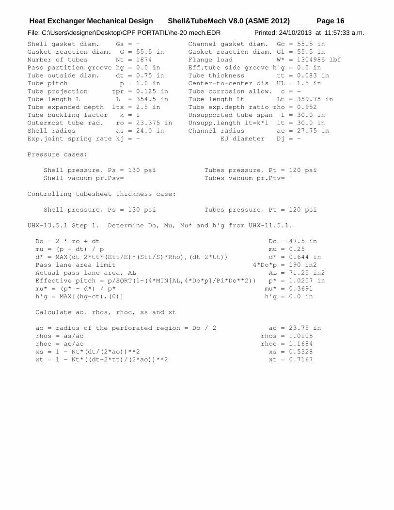
Heat Exchanger Mechanical Design Shell&TubeMech V8.0 (ASME 2012) Page 16
File: C:\Users\designer\Desktop\CPF PORTATIL\he-20 mech.EDR Printed: 24/10/2013 at 11:57:33 a.m.
Shell gasket diam. Gs = - Channel gas ket diam. Gc = 55.5 inGasket reaction diam. G = 55.5 in Gasket reac tion diam. G1 = 55.5 inNumber of tubes Nt = 1874 Flange load W* = 1304985 lbfPass partition groove hg = 0.0 in Eff.tube si de groove h'g = 0.0 inTube outside diam. dt = 0.75 in Tube thickn ess tt = 0.083 inTube pitch p = 1.0 in Center-to-c enter dis UL = 1.5 inTube projection tpr = 0.125 in Tube corros ion allow. c = -Tube length L L = 354.5 in Tube length Lt Lt = 359.75 inTube expanded depth ltx = 2.5 in Tube exp.de pth ratio rho = 0.952Tube buckling factor k = 1 Unsupported tube span l = 30.0 inOutermost tube rad. ro = 23.375 in Unsupp.leng th lt=k*l lt = 30.0 inShell radius as = 24.0 in Channel rad ius ac = 27.75 inExp.joint spring rate kj = - EJ diameter Dj = -
Pressure cases:
Shell pressure, Ps = 130 psi Tubes p ressure, Pt = 120 psi Shell vacuum pr.Psv= - Tubes v acuum pr.Ptv= -
Controlling tubesheet thickness case:
Shell pressure, Ps = 130 psi Tubes p ressure, Pt = 120 psi
UHX-13.5.1 Step 1. Determine Do, Mu, Mu* and h'g f rom UHX-11.5.1.
Do = 2 * ro + dt Do = 47.5 in mu = (p - dt) / p mu = 0.25 d* = MAX(dt-2*tt*(Ett/E)*(Stt/S)*Rho),(dt-2*tt)) d* = 0.644 in Pass lane area limit 4*Do*p = 190 in2 Actual pass lane area, AL AL = 71.25 in2 Effective pitch = p/SQRT(1-(4*MIN[AL,4*Do*p]/Pi*D o**2)) p* = 1.0207 in mu* = (p* - d*) / p* mu* = 0.3691 h'g = MAX[(hg-ct),(0)] h'g = 0.0 in
Calculate ao, rhos, rhoc, xs and xt
ao = radius of the perforated region = Do / 2 ao = 23.75 in rhos = as/ao rhos = 1.0105 rhoc = ac/ao rhoc = 1.1684 xs = 1 - Nt*(dt/(2*ao))**2 xs = 0.5328 xt = 1 - Nt*((dt-2*tt)/(2*ao))**2 xt = 0.7167

Heat Exchanger Mechanical Design Shell&TubeMech V8.0 (ASME 2012) Page 17
File: C:\Users\designer\Desktop\CPF PORTATIL\he-20 mech.EDR Printed: 24/10/2013 at 11:57:33 a.m.
UHX-13.5.2 Step 2. Calculate the shell axial stiff ness Ks, tube axial stiffness Kt, and stiffness factors Ks,t and J
Shell axial stiffness, Ks = PI*ts(Ds+ts)*Es/L Ks = 6114031 lbf/in Ks* = PI*(Ds+ts)/((L-2*l1)/(Es*ts)+(2*l1/(Es,1*ts ,1)) Ks* = - Tube axial stiffness, Kt = PI*tt(dt-tt)*Et/L Kt = 13786 lbf/in Factor Ks,t = Ks/(Nt*Kt) or Ks*/(Nt*Kt) Ks,t = 0.2367 J = 1 / (1 + (Ks/Kj)) J = 1.0
Calculate shell coefficients betas, ks, lambdas a nd deltas
betas = (12*(1-vs**2))**0.25 / ((Ds+ts)*ts)**0.5 betas = 0.3691 ks = betas*(Es*ts**3)/(6*(1-vs**2)) ks = 240436 lambdas=(6*Ds/h**3)*ks*(1+h*betas+(h**2*betas**2) /2) lambdas = 9335281 deltas = (Ds**2/(4*Es*ts))*(1-vs/2) deltas = 0.0000344
Calculate channel coefficients betac, kc, lambdac and deltac
betac = (12*(1-vc**2))**0.25 / ((Dc+tc)*tc)**0.5 betac = 0 kc = betac*(Ec*tc**3)/(6*(1-vc**2) kc = 0 lambdac=(6*Dc/h**3)*kc*(1+h*betac+(h**2*betac**2) /2) lambdac = 0 deltac = (Dc**2/(4*Ec*tc))*(1-vc/2) deltac = 0
NOTE: If the effect of plasticity used, Es or Ec will be Es* or Ec*
UHX-13.5.3 Step 3. Calculate h/p. If rho changes, recalculate d* and mu* from UHX-11.5.1. Determine E*/E and v* relative to h/p from UHX-11.5.2
Layout: Triangular Tubesheet th ickness h = 2.625 in
From fig. UHX-11.2 or UHX-11.3 - E*/E = 0.3725 v* = 0.3193 h/p = 2.625 mu* = 0.3691 Effective Tubsheet Mod.Elasticity E* = 10467052 psi
Parameter Xa = (24*(1-(v*)**2)*Nt*(Et*tt*(dt-tt)* ao**2)/((E*)*L*h**3))**0.25 Xa = 4.794
UHX-13.5.4 Step 4. Calculate diameter ratio K and c oefficient F.
K = A / Do K = 1.300 F = ((1-v*)/E*)*(lambdas+lambdac+E*Ln(K)) F = 1.086

Heat Exchanger Mechanical Design Shell&TubeMech V8.0 (ASME 2012) Page 18
File: C:\Users\designer\Desktop\CPF PORTATIL\he-20 mech.EDR Printed: 24/10/2013 at 11:57:33 a.m.
Parameters Zd, Zv, Zw and Zm from Table UHX-13.1
Psi1(Xa)=bei(Xa)+(1-v*)/Xa*ber'(Xa) Psi1(Xa) = 0.3509 Psi2(Xa)=ber(Xa)-(1-v*)/Xa*bei'(Xa) Psi2(Xa) = -4.9581
Za = bei'(Xa)*Psi2(Xa)-ber'(Xa)*Psi1(Xa) Za = 17.7908 Zd = (ber(Xa)*Psi2(Xa)+ bei(Xa)*Psi1(Xa))/(Xa**3* Za) Zd = 0.0139 Zv = (ber'(Xa)*Psi2(Xa)+ bei'(Xa)*Psi1(Xa))/(Xa** 2*Za) Zv = 0.0445 Zw = (ber'(Xa)*ber(Xa)+ bei'(Xa)*bei(Xa))/(Xa**2* Za) Zw = 0.0445 Zm = (ber'(Xa)**2+bei'(Xa)**2)/(Xa*Za) Zm = 0.307
Calculate Q1, Qz1, Qz2 and U
Phi = (1+v*) * F Phi = 1.4334 Q1 = (rhos-1-Phi*Zv)/(1+Phi*Zm) Q1 = -0.0369 Qz1 = ((Zd+Q1*Zw)*Xa**4)/2 Qz1 = 3.2352 Qz2 = ((Zv+Q1*Zm)*Xa**4)/2 Qz2 = 8.7434 U = ((Zw+(rhos-1)*Zm)*Xa**4)/(1+Phi*Zm) U = 17.4868
UHX-13.5.5 Step 5.
UHX-13.5.5(a) Calculate gamma (shown is max value f or all cases)
gamma = (alphatm*(Ttm-Tamb)-alphasm*(Tsm-Tamb))*L gamma = 0.1792 in (= 0 used for load cases 1, 2, 3)
UHX-13.5.5(b) Calculate omegas, omegas*, omegac, om egac*
omegas = rhos*ks*betas*deltas*(1+h*betas) omegas = 6.0783
omegas* = ao**2*((rhos**2-1)*(rhos-1))/4-omegas omegas* = -6.0469
omegac = rhoc*kc*betac*deltac*(1+h*betac) omegac = 0.0
omegac* = ao**2*(((rhoc**2+1)*(rhoc-1))/4- (rhos-1)/2)-omegac omegac* = 53.2049
UHX-13.5.5(c) Calculate gammab
gammab = (Gc-C)/Do gammab = -0.0579

Heat Exchanger Mechanical Design Shell&TubeMech V8.0 (ASME 2012) Page 19
File: C:\Users\designer\Desktop\CPF PORTATIL\he-20 mech.EDR Printed: 24/10/2013 at 11:57:33 a.m.
Fig.UHX-13.1(b) Controlling Case: UHX-1 3.4(a)(7)
UHX-13.5.6 Step 6. For each loading case calculate Ps', Pt', Pgamma, Pw, Prim, and effective pressure Pe.
Ps' = (xs+2*(1-xs)*vt+(2/Kst)*(Ds/Do)**2*vs- Ps' = 430.65 psi (Rhos**2-1)/(J*Kst)-((1-J)/(2*J*Kst))* (DJ**2-Ds**2)/Do**2 ) * Ps
Pt' = (xt+2*(1-xt)*vt+1/(J*Kst))*Pt Pt' = 613.47 psi
Pgamma = (Nt*Kt/(Pi*ao**2))*gamma Pgamma = 2612.09 psi
PW = -(U/ao**2)(gammab/(2*Pi))*W* PW = 372.77 psi
Prim = -(U/ao**2)*((omegas*)(Ps)-(omegac*)(Pt) ) Prim = 222.3 psi
Effective pressure, Pe
Pe = J*Kst/(1+J*Kst(Qz1+(rhos-1)Qz2)) * (Ps'-Pt'+Pgamma+PW+Prim) Pe = 400.43 psi
UHX-13.5.7 Step 7. For each loading case calculate Q2 and Q3.
Q2 = ((omegas*)*Ps-(omegac*)*Pt)- ((omegas*(Ps*)-omegac*(Pc*))+ (gammab/(2*Pi))*(W*)/(1+Phi*Zm) Q2 = -13329.4561
Q3 = Q1 + 2*Q2 / (Pe*ao**2) Q3 = -0.155
Using Xa and Q3, determine coefficient Fm for eac h loading case from either Table UHX-13.1 or Figs. UHX-13.3.-1 and UH X-13.3.-2.
Controlling x for Fm, x = 4.794

Heat Exchanger Mechanical Design Shell&TubeMech V8.0 (ASME 2012) Page 20
File: C:\Users\designer\Desktop\CPF PORTATIL\he-20 mech.EDR Printed: 24/10/2013 at 11:57:33 a.m.
Fm(x) = (Qv(x) + Q3 * Qm(x)) / 2 Fm(x) = -0.0775 Fm = MAX|Fm(x)| Fm = 0.0775
For each loading case, calculate the bending stre ss in the tubesheet
sigma = (1.5*Fm/mu*)*(2*ao/(h-h'g))**2 * Pe sigma = 41289 psi
|sigma| <= 2*Sy 41289 psi <= 67200 psi
UHX-13.5.8 Step 8. For each loading case, calculate the maximum shear stress in the tubesheet across the tubesheet diam eter
Area enclosed by perimeter AP = 1604.74 in2 Perimeter of the tube layout CP = 154.7128 in Shear diameter, Dia = DL or Do DL = 4*AP/CP DL = 41.4896 in |Pe| = 400.43 Do = 47.5 in 3.2*S*mu*h/Do = 884.21 Dia = 47.5 in
Ligament efficiency, mu mu = (p-dt)/p = 0.25
Controlling x for FQ, x = 4.794
FQ(x) = (Qb(x) + Q3 * Qa(x)) FQ(x) = 1.0 FQ = MAX|FQ(x)| FQ = 1.0
Shear stress at periphery, tau = ( 1/(4*mu))*(Di a/h)*Pe tau = 7246 psi
Max shear across diameter, tau = (FQ/(4*mu))*(Di a/h)*Pe tau = 7246 psi
|tau| <= 0.8*S 7246 psi <= 16000 psi

Heat Exchanger Mechanical Design Shell&TubeMech V8.0 (ASME 2012) Page 21
File: C:\Users\designer\Desktop\CPF PORTATIL\he-20 mech.EDR Printed: 24/10/2013 at 11:57:33 a.m.
UHX-13.5.9 Step 9. Perform this step for each load ing case.
UHX-13.5.9(a) Check the axial tube stress.
UHX-13.5.9(a)(1) For each loading case determine co efficient Ft,min and Ft,max from Table UHX-13.2 and calculate the two extreme values of sigmat,1 and sigmat,2. These values may be po sitive or negative
Ft(x) = [Zd(x)+Q3*Zw(x)]*(Xa**4/2) for 0 <= x <= Xa
Ft,min = MIN[[Zd(x)+Q3*Zw(x)]*(Xa**4/2)] Ft,min = -0.2768 Ft,max = MAX[[Zd(x)+Q3*Zw(x)]*(Xa**4/2)] Ft,max = 1.8584
UHX-13.5.9(a)(1)(a) When Pe <> 0:
sigmat,1 = ((Ps*xs-Pt*xt)-Pe*Ft,min)/(xt-xs) sigmat,1 = 512 psi sigmat,2 = ((Ps*xs-Pt*xt)-Pe*Ft,max)/(xt-xs) sigmat,2 = -4137 psi
UHX-13.5.9(a)(2) Determine sigmat,max
sigmat,max = MAX(|sigmat,1|,|sigmat,2|) sigmat,max = 4137 psi Allowable tube stress in tension St = 26824 psi
UHX-13.5.9(b) Check the tube-to-tubesheet joint
UHX-13.5.9(b)(1) Calculate the tube-to-tubesheet jo int load, Wt
Wt = sigmat,max*Pi*(dt-tt)*tt Wt = 720 lbf
UHX-13.5.9(b)(2) Determine the maximum allowable lo ad for the tube-to-tubesheet joint design Lma x
UW-18(d) max load = - UW-20 max load = - App.A max No test load = 2333 lbf App.A max test load = 2799 lbf Lmax = 2333 lbf
UHX-13.5.9(c) Check the tubes for buckling.
UHX-13.5.9(c)(1) Calculate largest buckling length lt
Tube buckling factor k = 1 Unsupported tube span l = 30.0 in
lt = largest unsupported buckling length = k*l lt = 30.0 in
UHX-13.5.9(c)(2) Calculate rt, Ft and Ct
rt = SQRT(dt**2+(dt-2*tt)**2)/4 rt = 0.2376 in Ft = lt/rt Ft = 126.242 Ct = SQRT(2*PI**2*(Et/Syt)) Ct = 155.2938
UHX-13.5.9(c)(3) Determine the factor of safety Fs
Fsc = (3.25-0.25*(Zd+Q3*Zw)*Xa**4) = 2.3251

Heat Exchanger Mechanical Design Shell&TubeMech V8.0 (ASME 2012) Page 22
File: C:\Users\designer\Desktop\CPF PORTATIL\he-20 mech.EDR Printed: 24/10/2013 at 11:57:33 a.m.
Fs = MAX((1.25, Fsc) (Fs need not be > 2) Fs = 2.0
UHX-13.5.9(c)(4) Determine the buckling stress limi t Stb
For Ct <= Ft Stb = MIN[(1/Fs)*(PI**2*Et/(Ft**2), St] Stb = - For Ct > Ft Stb = MIN[(Syt/Fs)*(1-Ft/(2*Ct)) , St] Stb = 6826 psi
UHX-13.5.9(c)(5) Determine sigmat,min
sigmat,min = MIN(sigmat,1 , sigmat,2) sigmat,min = -4137 psi
|s igmat,min| <= Stb 4137 psi <= 6826 psi

Heat Exchanger Mechanical Design Shell&TubeMech V8.0 (ASME 2012) Page 23
File: C:\Users\designer\Desktop\CPF PORTATIL\he-20 mech.EDR Printed: 24/10/2013 at 11:57:33 a.m.
UHX-13.5.10 Step 10. For each loading case, calcula te the stresses in the shell and /or channel integral with the tubesheet .
Calculate the axial membrane stress sigmasm, axia l bending stress sigmasb and total axial stress sigmas in the shell at its junction to the tubesheet
sigmasm = ao**2/[ts*(2*as+ts)]*[Pe+(rhos**2-1) *(Ps-Pt)]+as**2/[ts*(2*as+ts)]*Pt sigmasm = 12169 psi
sb1 = (6/ts**2)*ks sb2 = betas*deltas*Ps sb3 = 6*(1-(v*)**2)/(E*)*(ao**3/h**3)*(1+(h*betas /2)) sb4 = Pe*(Zv+Zm*Q1)+(2/ao**2)*Zm*Q2 sigmasb = sb1*(sb2+sb3*sb4) sigmasb = 5453 psi
sigmas = |sigmasm| + |sigmasb| sigmas = 17622 psi
sigmas <= 2*Sy 17622 psi <= 68880 psi
ASME VIII-1 2011a UHX-13 - Rules for the Design of Fixed TubesheetsASME Fig.UHX-13.1(b) All Load Cases
Controlling case: ***Load case: 1 2 3 4 5 6 7
Tubeside press, Pt 120 0 120 0 120 0 120Shellside press, Ps 0 130 130 0 0 130 130Axial diff.Th.Exp 0.0 0.0 0.0 0.179 2 0.1792 0.1792 0.1792
TubSh Bending stress -15407 2769 16860 2941 3 38520 32181 41289Max TubSh Bending st 30000 30000 30000 6720 0 67200 67200 67200Min TubSh thk 1.8812 0.7974 1.9679 1.736 7 1.9874 1.8166 2.0576
TubSh Shear stress -1074 1090 1156 7151 6156 8241 7246Max TubSh Shear str 16000 16000 16000 1600 0 16000 16000 16000Min TubSh thk 0.1284 0.1789 0.0504 1.173 2 1.0099 1.3521 1.1888
Tubesheet thickness 2.625 2.625 2.625 2.62 5 2.625 2.625 2.625

Heat Exchanger Mechanical Design Shell&TubeMech V8.0 (ASME 2012) Page 24
File: C:\Users\designer\Desktop\CPF PORTATIL\he-20 mech.EDR Printed: 24/10/2013 at 11:57:33 a.m.
Component: Rear TubesheetASME Fig.UHX-13.1(b) All Load Cases
Load case: 1 2 3 4 5 6 7
Tubes controlling: ***Tubes stress st,1 -1032 538 1187 828 -27 1367 512Tubes stress st,2 1747 -560 -642 -506 2 -3654 -5622 -4137Max Tubes tens.str 13412 13412 13412 2682 4 26824 26824 26824Max Tubes comp.str 10921 7497 6826 6826 6826 6826 6826
Shell controlling: ***Total shell stress 29299 15572 16658 2225 1 19357 37822 17622Max shell stress 30000 30000 30000 6888 0 68880 68880 68880Max shell stress EP 68880 68880 68880
Channel controlling: - - - - - - -Total channel stress - - - - - - -Max channel stress - - - - - - -Max channel str. EP - - -
EP factor - Facts(*) 1.0 1.0 1.0EP factor - Factc(*) 1.0 1.0 1.0 (* ) <= 1 used in calculations
Tube stress across the tubesheet diameter (0 <= x < = Xa)
Load case: 1 2 3 4 5 6 7
Ft,min -2.401 -0.494 -13.837 -0.38 6 -0.238 -0.4 -0.277Ft,max 9.416 2.858 5.968 2.35 6 1.723 2.422 1.858
sigmat,1 -1032 538 1187 828 -27 1367 512Location x 2.013 0.096 4.794 0.09 6 0.096 0.096 0.096
sigmat,2 1747 -560 -642 -506 2 -3654 -5622 -4137Location x 4.794 4.794 2.589 4.79 4 4.506 4.794 4.698
Maximum stress 13412 13412 13412 2682 4 26824 26824 26824Max buckling stress 10921 7497 6826 6826 6826 6826 6826

Heat Exchanger Mechanical Design Shell&TubeMech V8.0 (ASME 2012) Page 25
File: C:\Users\designer\Desktop\CPF PORTATIL\he-20 mech.EDR Printed: 24/10/2013 at 11:57:33 a.m.
Shell axial membrane stress, sigmasm Units: psi
Load case: 1 2 3 4 5 6 7
|sigmasm| 1785 1465 3250 9192 10704 10658 12169 Allowable stress 17000 17000 17000 4000 0 40000 40000 40000 (JE*S) JE = 0.85
Compression: sigmasm - - - - - - - Allowable stress - - - - - - -
ASME VIII-1 2011a UHX-13 - Fixed Tubesheets - All Cases
Load case Ps Pt Gamma Ps* Pc* W* psi psi in psi psi lbf
- 1 - 0 120 0 0 0 311018- 2 - 130 0 0 0 0 0- 3 - 130 120 0 0 0 311018- 4 - 0 0 0.1792 0 0 1304985- 5 - 0 120 0.1792 0 0 1304985- 6 - 130 0 0.1792 0 0 1304985- 7 - 130 120 0.1792 0 0 1304985
Load case P's P't Pgamma Pomega Pw Prim Pe psi psi psi psi p si psi psi
- 1 - 0 613.5 0 0 88 .8 197.9 -43.3- 2 - 430.7 0 0 0 0 24.4 60.2- 3 - 430.7 613.5 0 0 88 .8 222.3 17- 4 - 0 0 2612.1 0 37 2.8 0 395.2- 5 - 0 613.5 2612.1 0 37 2.8 197.9 340.2- 6 - 430.7 0 2612.1 0 37 2.8 24.4 455.4- 7 - 430.7 613.5 2612.1 0 37 2.8 222.3 400.4

Heat Exchanger Mechanical Design Shell&TubeMech V8.0 (ASME 2012) Page 26
File: C:\Users\designer\Desktop\CPF PORTATIL\he-20 mech.EDR Printed: 24/10/2013 at 11:57:33 a.m.
Load case Q2 Q3 Fm Sigma Sigma All FQ Tau Tau All psi psi psi psi
- 1 - -6423.6 0.4896 0.2677 -15407 30000 1 .3718 -1074 16000- 2 - -545.9 -0.0691 0.0345 2769 30000 1 1090 16000- 3 - -6969.5 -1.4914 0.7457 16860 30000 3 .7609 1156 16000- 4 - -8350 -0.1119 0.0559 29413 67200 1 7151 16000- 5 - -12783.6 -0.1702 0.0851 38520 67200 1 6156 16000- 6 - -8895.9 -0.1062 0.0531 32181 67200 1 8241 16000- 7 - -13329.5 -0.155 0.0775 41289 67200 1 7246 16000
ASME VIII-1 2011a UHX-13 - Fixed Tubesheets - All C ases
Load case Fs Ft,min Ft,max Sigt,1 Sig t,2 Sigt,All Stb psi p si psi psi
- 1 - 1.25 -2.401 9.416 -1032 17 47 13412 10921- 2 - 1.8209 -0.494 2.858 538 -5 60 13412 7497- 3 - 2 -13.837 5.968 1187 -6 42 13412 6826- 4 - 2 -0.386 2.356 828 -5 062 26824 6826- 5 - 2 -0.238 1.723 -27 -3 654 26824 6826- 6 - 2 -0.4 2.422 1367 -5 622 26824 6826- 7 - 2 -0.277 1.858 512 -4 137 26824 6826
Load case Sigsm Sigsb |Sigs| Sigsall Sigcm Sigcb |Sigc| Sigcall psi psi psi psi psi psi psi psi
- 1 - 1785 -27514 29299 30000 - - - -- 2 - 1465 14106 15572 30000 - - - -- 3 - 3250 -13408 16658 30000 - - - -- 4 - 9192 13058 22251 68880 - - - -- 5 - 10704 -8654 19357 68880 - - - -- 6 - 10658 27164 37822 68880 - - - -- 7 - 12169 5453 17622 68880 - - - -

Heat Exchanger Mechanical Design Shell&TubeMech V8.0 (ASME 2012) Page 27
File: C:\Users\designer\Desktop\CPF PORTATIL\he-20 mech.EDR Printed: 24/10/2013 at 11:57:33 a.m.
Type of tube-to-TS joint: 'k' - Expanded with no gr ooves
Load case: 1 2 3 4 5 6 7Wt tube-TS Load, lbf 304 97 206 880 635 978 720Allowable no-test 1166 1166 1166 2333 2333 2333 2333Allowable test 1400 1400 1400 2799 2799 2799 2799Factor k 1 1 1 2 2 2 2Max load K*At*Sa 2333 2333 2333 4665 4665 4665 4665
Allowable Loads per ASME Section VIII Div.1 2011a A ppendix A
No T est TestType Joint description fr L max fr Lmax a Welded only a >= 1.4t 0.8 3 732 1 4665 b Welded only t <= a < 1.4t 0.55 1 283 0.7 1633 b-1 Welded only a <= t 0 0 * 0.7 3266 e Welded a >= 1.4t and expanded 0.8 3 732 1 4665 f Welded a < 1.4t exp.with 2 grooves 0.75 3 499 0.95 4432 g Welded a < 1.4t exp.with 1 groove 0.65 3 032 0.85 3965 h Welded a < 1.4t exp.with no grooves 0.5 2 333 0.7 3266 i Expanded with 2 grooves 0.7 3 266 0.9 4199 j Expanded with 1 groove 0.65 3 032 0.8 3732 k Expanded with no grooves 0.5 2 333 0.6 2799* = Load calculated exceeds code allowable for this joint type.For joints types a,b,b-1,c,d,e : Lmax = A t*Sa*frFor joints types f,g,h, : Lmax = A t*Sa*fe*fr*fyFor joints types i,j,k : Lmax = A t*Sa*fe*fr*fy*ft
Cross-sectional area At = 0.1739 in2 Tube allowa ble stress Sa = 13412 psiMax stress St = At*Sa St = 2333 psiTubesheet yield str. Stt = 33600 psi Tube yield stress Stu = 23000 psife = (ltx/do or 1) fe = 1 Min Yield S tr. (Stt,Stu) = 23000 psift = (Po+Pt)/Po ft = 1 fy = Stt/St u = 1.46ft = used (0<ft<=1) ft = 1 fy = used ( 0<fy<=1) fy = 1Tube OD do = 0.75 in Expanded le ngth ltx = 2.5 inTube thickness t = 0.083 in TubSh mean metal tmp T = 300 FTubes Mod.Elasticity EtT = 28100000 psi TubSh Mod.E last. EsT = 28100000 psiTubes Coef.Th.Exp.(*) at = 6.9 TubSh Coef. Th.Exp.(*) as = 6.9Friction coefficient muF = 0.5 (*)=*10**6 in/in/F
Tube to tube hole Interfacial Pressure:
Po = ((do*t-t**2)*st)/(do*ltx*muF) Po = 1358 psiPt = (T-Tamb)*(at-as)*(EtT*EsT)/(EtT+EsT) Pt = 0 psi
For joint types i, j, k: Po + Pt <= 0.58*SigmaM 1358 psi <= 13340 psi

Heat Exchanger Mechanical Design Shell&TubeMech V8.0 (ASME 2012) Page 28
File: C:\Users\designer\Desktop\CPF PORTATIL\he-20 mech.EDR Printed: 24/10/2013 at 11:57:33 a.m.
UHX-9 Tubesheet Flanged Extension
G = diameter of gasket load reaction G = 55.0 inhG = gasket moment arm hG = 1.625 inSa = allowable stress for tubesheet extension at ambient temperature Sa = 20000 psiSd = allowable stress for tubesheet extension at design temperature Sd = 20000 psiTa = ambient temperature Ta = 70 FTd = design temperature Td = 300 FWo = flange design bolt load, opeating conditions Wo = 311018 lbfWg = flange design bolt load, gasket seating Wg = 1304985 lbf
Minimum required thickness of the tubesheet flanged extension
hro = SQRT((1.9 * Wo * hG) / (Sd * G)) hro = 0.9343 in
hrg = SQRT((1.9 * Wg * hG) / (Sa * G)) hrg = 1.9139 in
hr = MAX[hro, hrg] hr = 1.9139 in
Unperforated tubesheet segment - minimum thickness
UG-34(c)(3)
Unperf. short span d = 1.875 in Unperf. lon g span D = 18.5994 inControlling pressure P = 130 psi Allowable s tress S = 20000 psiFactor C C = 0.3 Joint effic iency E = 1Z = 3.4 - (2.4 * d) / D = 3.158 (max 2.5) Z = 2.5
Effect of bolt load on unperforated tubesheet segme nt, if any
Bolt circle BC = 58.25 in Segment len gth L = 182.9978 inBolt load W = 311018 lbf Gasket mome nt arm hg = 1.625 in
Minimum thickness of unperforated segment:
t = d * SQRT(Z*C*P/S*E + 6*W*hg/S*E*L*d* *2) = 0.9196 in