tubeless microfluidic angiogenesis assay with three ...mmb.bme.wisc.edu/research/beebepubs/beebe...
TRANSCRIPT
at SciVerse ScienceDirect
Biomaterials 34 (2013) 1471e1477
Contents lists available
Biomaterials
journal homepage: www.elsevier .com/locate/biomater ia ls
Tubeless microfluidic angiogenesis assay with three-dimensionalendothelial-lined microvessels
Lauren L. Bischel a,b, Edmond W.K. Young a,b, Brianah R. Mader a,b, David J. Beebe a,b,*
aDepartment of Biomedical Engineering, University of WisconsineMadison, Madison, WI 53706, USAbWisconsin Institute for Medical Research, University of WisconsineMadison, Madison, WI 53706, USA
a r t i c l e i n f o
Article history:Received 22 October 2012Accepted 3 November 2012Available online 26 November 2012
Keywords:Tubeless microfluidic3D angiogenesis assayLumensExtracellular matrix hydrogelMicrovesselTissue Engineering
* Corresponding author. Wisconsin Institute for MedBiomedical Engineering, University of WisconsineMaRoom 6009, Madison, WI 53705, USA. Tel.: þ1 608 26
E-mail address: [email protected] (D.J. Beebe).
0142-9612/$ e see front matter � 2012 Elsevier Ltd.http://dx.doi.org/10.1016/j.biomaterials.2012.11.005
a b s t r a c t
The study of angiogenesis is important to understanding a variety of human pathologies includingcancer, cardiovascular and inflammatory diseases. In vivo angiogenesis assays can be costly and time-consuming, limiting their application in high-throughput studies. While traditional in vitro assays mayovercome these limitations, they lack the ability to accurately recapitulate the main elements of thetissue microenvironment found in vivo, thereby limiting our ability to draw physiologically relevantbiological conclusions. To bridge the gap between in vivo and in vitro angiogenesis assays, severalmicrofluidic methods have been developed to generate in vitro assays that incorporate blood vesselmodels with physiologically relevant three-dimensional (3D) lumen structures. However, these modelshave not seen widespread adoption, which can be partially attributed to the difficulty in fabricating thesestructures. Here, we present a simple, accessible method that takes advantage of basic fluidic principlesto create 3D lumens with circular cross-sectional geometries through ECM hydrogels that are lined withendothelial monolayers to mimic the structure of blood vessels in vitro. This technique can be used topattern endothelial cell-lined lumens in different microchannel geometries, enabling increased flexibilityfor a variety of studies. We demonstrate the implementation and application of this technique to thestudy of angiogenesis in a physiologically relevant in vitro setting.
� 2012 Elsevier Ltd. All rights reserved.
1. Introduction
Angiogenesis, the neovascularization of blood vessels frompreexisting vasculature, is an important biological process involvedin normal growth and development, as well as in various humanpathologies including cancer, cardiovascular diseases, and inflam-matory disorders. In cancer specifically, angiogenesis is necessaryfor tumors to grow beyond a critical size of a few millimeters.Without new vessel formation and proper blood supply, tumor cellstoo distant (>w200 mm) from existing vessels would lack thesupply of oxygen and nutrients essential for cell survival andproliferation [1]. Because of the importance of angiogenesis intumor growth, metastasis, and overall cancer progression, thera-peutic strategies have been developed around the concept ofinhibiting angiogenesis with drugs and other angiostatic agents torestrict blood supply to the tumor. This is an area in drug discovery
ical Research, Department ofdison, 1111 Highland Avenue,2 2260.
All rights reserved.
that continues to undergo intense study [2,3]. The ability to studyangiogenesis and investigate the effects of various factors onangiogenic responses is thus critical for furthering our under-standing of the mechanisms of cancer development, as well as forthe development of new and effective therapies.
Current angiogenesis assays span a wide range of methods thatinclude in vivo preparations, organ cultures, and in vitro assays [4].While in vivo methods such as the popular cranial window anddorsal skin chamber preparations have been instrumental inproviding deep insights into the angiogenic process, these prepa-rations are time-consuming, labor-intensive, expensive, andrequire significant skill in surgery, and thus are unsuitable asroutine assays for widespread adoption or for high-throughputtesting. Organ cultures such as the aortic ring and chick aorticarch assays are simpler preparations than in vivo methods, andmaintain important elements of the complex tissue microenvi-ronment, but tissue isolation, culture, and explant outgrowth ofaortas can be time-consuming, challenging to do repeatedly andconsistently, and difficult to scale up [5]. Thus, for high-throughputapplications such as screening of large drug compound librariesand combinatorial testing of cellular and extracellular factors,a more suitable approach is to employ in vitro assays that rely on
L.L. Bischel et al. / Biomaterials 34 (2013) 1471e14771472
simple, accessible cell cultures and readily available substrates, andcircumvent laborious lab procedures that involve the handling ofanimals and tissue explants. However, an often-cited major short-coming of current in vitro assays is their inability to accuratelyrecapitulate the main elements of the tissue microenvironmentfound in vivo, and this issue limits our ability to draw accuratebiological conclusions. Therefore, an urgent need exists for thedevelopment of improved in vitro angiogenesis assays that cancontinue to offer high-throughput capacity and simple convenientoperationwhile significantly enhancing the physiological relevanceof the in vitro tissue microenvironment.
Recently, microfluidics technology has been applied to improvethe spatiotemporal control of the cell or tissue microenvironment[6], thereby enabling the development of new and useful cell-basedassays for biological research [7e10]. In particular, microfluidics hasprovided significant advances in new models of vascular function[11e15], with several notable designs specifically tailored to studythe processes associated with angiogenesis [16,17]. While thesemethods have demonstrated the potential benefits of working atthe microscale, and clearly offer more sophistication for studyingangiogenesis, there remain significant challenges related to thefabrication and maintenance of blood vessel mimics that closelyresemble three-dimensional vessel lumens in vivo. Furthermore, itis unclear whether these systems can be easily scalable for appli-cations requiring increased throughput.
Here, we present a simple, accessible method that takesadvantage of basic fluidic principles to create three-dimensional(3D) lumens with circular cross-sectional geometries lined with
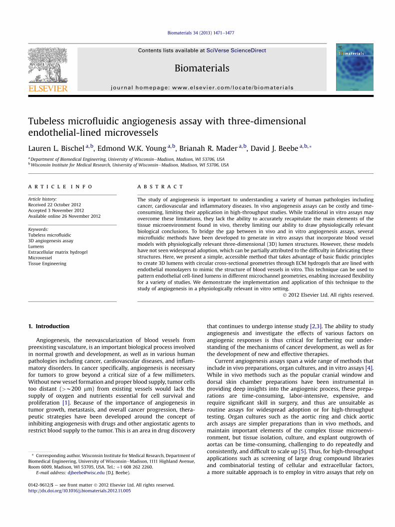
Fig. 1. Passive pumping-based microfluidic angiogenesis assay with 3D cylindrical lumenMicrochannel systems can be (B) single, (C) double, or (D) triple channel designs, and are arw10 mm.
patent 3D endothelial monolayers applied to study angiogenesis inphysiologically relevant in vitro microenvironments. The methodrequires only the use of a micropipette, and has the potential to bescaled into large arrays interfaced with automated liquid handlersas previously shown [18e20]. The method also allows incorpora-tion of other cell types for organ-like cocultures that mimic thestructure and organization of blood vessel lumens in vivo. Wedescribe the development and application of 3D endothelial-linedlumens (ELL) with proper barrier function, biological response toVEGF gradients in the form of angiogenic sprouting, and furtherdemonstrate the flexibility of the method for generating vesselnetworks on demand, without the need for re-designing moldsfrom scratch.
2. Materials and methods
2.1. Device fabrication
Polydimethylsiloxane (PDMS, Sylgard 184 Silicone Elastomer Kit, Dow Corning,Midland, MI) elastomer base and curing agent were mixed at a 10:1 ratio anddegassed for 45 min under vacuum at room temperature. The degassed PDMS wasthen poured over SU-8 master molds that were generated using standard softlithography methods [21]. PDMS was cured at 80 �C for 4 h. Microchannel geome-tries used in these experiments varied depending on the application (Fig. 1).
2.2. Cell culture
Human umbilical vein endothelial cells (HUVECs) were obtained from Lonza(Walkersville, MD, USA) and maintained with endothelial growth medium (EGM-2)with Bullet Kit (EGM-2MV; Lonza, Walkersville, MD, USA) on regular tissue cultureflasks pre-coated with 2 mg/cm2
fibronectin (FN) (SigmaeAldrich, St. Louis, MO,
s. (A) Illustration of a triple channel design with connecting microchannels. (BeD)rayable. Devices are plasma-treated and bonded to glass-bottom Petri dishes. Scale bar
L.L. Bischel et al. / Biomaterials 34 (2013) 1471e1477 1473
USA). 10T1/2 mouse smooth muscle cells were obtained from ATCC (Manassas, VA,USA) and maintained in Eagle’s Basal Medium (EBM) (Sigma, St. Louis, MO, USA)supplemented with 10% fetal bovine serum (Invitrogen, Carlsbad, CA, USA) and 1%penicillin/streptomycin (Invitrogen, Carlsbad, CA, USA). The EBM-based media for10T1/2 cells was changed to the EGM-2-based media for HUVECs 24 h prior to usingcells in coculture experiments.
2.3. Hydrogel preparation
A hydrogel consisting of extracellular matrix (ECM) proteins made of a finalconcentration of 6.0 mg/mL Type I collagen (rat tail, BD Biosciences, Bedfrod, MA,USA), and 25% Matrigel (BD Biosciences, Bedford, MA, USA) was used in all experi-ments. To make roughly 125 mL of hydrogel solution, 1.56 mL of a basic solution (5.0 NNaOH) and 20 mL of 5� PBS was added to 78 mL of the collagen I and incubated on ice
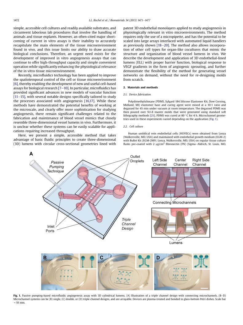
Fig. 2. (A) Viscous finger patterning is used to pattern the initial lumen structure through anPassive pumping is used to flowmedia through the ECM solution, pushing out the center. Folthrough the hydrogel. (B) Methods used to line lumens with endothelial cells to generate ELLused to pattern one or three ELL in a triple microchannel. Note: when patterning an intercomain channels. The entire channel is filled at once and viscous finger patterning is perform
for a period between 5 and 10 min to apply an additional nucleation phase prior toadding 25 mL of Matrigel [22]. These volumes were scaled up to prepare the amountof hydrogel solution needed for a given experiment.
2.4. Lumen patterning
Prior to patterning lumens, devices were oxygen-plasma-treated to bond thePDMS channels to a glass surface (the inside of a glass-bottom Petri dish, MatTek,Ashland, ME, USA), and to render the inside of the chambers hydrophilic. Thedevices were coated with 100 mg/mL FN to facilitate adhesion of the hydrogel to thechannel walls. After 20 min incubation at room temperature, the FN solution wasaspirated from the channel. To pattern a lumen through a hydrogel in a singlemicrochannel, viscous finger patterning was used as previously described [20].Briefly, a pre-polymerized hydrogel solutionwas dispensed into amicrochannel, and
ECM hydrogel. A microchannel is filled with a pre-polymerized ECM hydrogel solution.lowing incubation for 10 min at 37 �C to complete polymerization, a lumen is patterneds. (C) Methods used to pattern two ELLs lumens in a double microchannel. (D) Methodsnnected network in double channels, the diffusion channels are the same height as theed prior to incubation.

L.L. Bischel et al. / Biomaterials 34 (2013) 1471e14771474
media was then dispensed through the hydrogel solution via surface tension-basedpassive pumping [23]. After incubating the hydrogel in themicrochannels for 10minat 37 �C, polymerization of the hydrogel was completed, resulting in a patternedlumen through a hydrogel (Fig. 2A).
To pattern two or three lumens connected by a spacer hydrogel, a microfluidicdesign was used that consisted of two or three 500-mm tall single microchannelsconnected by three 100-mm tall perpendicular diffusion channels between each pairof microchannels. To pattern two lumens in a double microchannel (Fig. 2C), one ofthe channels was first filled with a hydrogel solution, which pinned at the outer edgeof the diffusions channels due to surface tension. The hydrogel solution was thenaspirated from the channel without any polymerization, leaving the solution behindonly in the diffusion channels. The channels were incubated at 37 �C for 10 min topolymerize the hydrogel. A hydrogel solution was then delivered into both of thechannels and viscous finger patterningwas performed, treating both of the channelsas single microchannels, to pattern a lumen through the hydrogel solutions. Thechannels were incubated for 10 min at 37 �C to complete polymerization. To patternthree lumens in a triple microchannel (Fig. 2D), the center channel was first filledwith a hydrogel solution, which pinned at the outer edge of the diffusions channelson both sides due to surface tension. The hydrogel solution was then aspirated formthe center channel without any polymerization, leaving the solution behind only inthe diffusion channels. The channels were incubated at 37 �C for 10 min to allow thesolution to polymerize. A hydrogel solution was delivered into the three mainchannels and viscous finger patterning was performed, treating each of the con-nected microchannels as single microchannels, to pattern a lumen through thehydrogel solutions in each of the channels. The channels were incubated for 10 minat 37 �C to complete polymerization. To pattern an interconnected network oflumens, two 500-mm tall single microchannels connected by three 500-mm tallperpendicular channels were used. The entire double microchannel was filled witha hydrogel solution. Viscous finger patterning was performed from both input ports.The hydrogel was patterned such that two main lumens were formed and inter-connected by three perpendicular lumens.
For angiogenesis experiments, a single lumen in the center channel of a triplemicrochannel was patterned, leaving the two side channels open. Lumen patterningwas achieved by themethod described above, where culturemediawas added to thetwo side channels.
2.5. Endothelial cell seeding
To line the lumen with HUVECs and generate ELLs, two strategies were used toensure uniform cell seeding (Fig. 2B). In the first strategy (motorized option), passivepumping was used to add 2 mL of a cell solution at 40,000 cells/mL to each lumen.With the lid of the Petri dish securely attached, the dish containing the
Fig. 3. ELLs were cultured for 48 h and stained for CD31 (green) and nuclei (blue). (A)e(C) Ca single microchannel. (E) Volume-rendered cross section of an ELL in a single microchannelrendered cross section of three ELLs in a triple microchannel. Scale bar represents 100 mm. (Fthe web version of this article.)
microchannels was taped to the rod that is attached to a motor (BBQ RotisserieVariable Speed Reversible Brushless Gear Motor, Wondermotor, CA, USA). Thismotor was placed inside an incubator at 37 �C and tuned to rotate the dishes at2 RPM for 30 min to allow cell attachment. In the second strategy (manual option),a cell solution was prepared at 10,000 cells/mL and 2 mL were added to the lumens(Fig. 1B). The channels were incubated for 15 min at 37 �C to allow the cells to attachto the bottom of the lumen. 2 mL of the cell solution was added again to the channelvia passive pumping, and the channels were rotated 90� and incubated for 15 min at37 �C. This process was repeated with subsequent 90� rotations until all four sides ofthe lumen were coated [24]. The cell solution was kept on ice between cell seedingsteps. After either procedure, channels were righted and incubated at 37 �C fora minimum of 2 h before being perfused with fresh media via passive pumping torinse unattached cells.
2.6. Endothelial barrier structure and function
ELLs in single microchannels were cultured for 48 h with media replacementsevery 8e12 h. Permeability of the endothelial monolayers were determined byflowing FITC-labeled bovine serum albumin (BSA) (Molecular Probes, Eugene, OR,USA) into the lumens and calculating permeability coefficients using methodssimilar to those described by others [25,26]. Briefly, fluorescence images were takenat 1 min intervals for 20 min. Samples were imaged with an Olympus IX81 (CenterValley, PA, USA) with a fluorescent attachment (BH2-RFL-T3, Center Valley, PA, USA),and images were acquired using SlideBook 5.0 (Intelligent Imagaing Innovations,Inc., Denver, CO, USA). The permeability coefficient P was calculated from theequation P ¼ ð1=DIÞðdI=dtÞ0r=2, where DI is the step increase in backgroundintensity immediately after adding FITC-labeled BSA, ðdI=dtÞ0 is initial rate ofincrease in intensity (over the first 5 min) in the gel surrounding each lumen, and r isthe radius of the lumen. The average permeability coefficient was determined byaveraging coefficient values from 8 separate devices across 3 independentexperiments.
To confirm that endothelial cells were forming cell junctions, ELLs were culturedfor 48 h, fixed with 4% paraformaldehyde (PFA) (Fisher Scientific, Hampton, NH,USA), and stained for platelet endothelial cell adhesion molecule (PECAM-1; orCD31). ELLs were blocked with 3% BSA, immunolabeled with mouse anti-humanCD31 antibodies (20 mg/mL, Santa Cruz Biotechnology, Inc, Santa Cruz, CA, USA),and fluorescently labeled with AlexaFlour 488 (1:200 dilution, Molecular Probes,Eugene, OR, USA). Hoechst 33342 (10 mg/mL, Molecular Probes) was used to stain thenuclei. Samples were imaged using an A1RSi confocal microscope (Nikon Instru-ments, Tokyo, Japan) and images were acquired using NIS Elements Advancedsoftware (Nikon). Images files were converted using Fiji software, and volume-rendered images were generated using OsiriX.
onfocal slices of an ELL at the specified height. (D) Volume-rendered image of an ELL in. (F) Volume-rendered cross section of two ELLs in a double microchannel. (G) Volume-or interpretation of the references to color in this figure legend, the reader is referred to

L.L. Bischel et al. / Biomaterials 34 (2013) 1471e1477 1475
2.7. Gradient characterization
Characterization of a gradient in a triple microchannel was performed bypatterning a lumen through and ECM hydrogel in the center chamber, and adding toone of the side chambers 50 ng/mL FITC-labeled dextran (40 kDa, SigmaeAldrich, St.Louis, MO USA), a protein with a similar molecular weight to vascular endothelialgrowth factor (VEGF). Fluorescence intensity was monitored and measured everyhour for 12 h. Samples were imaged with an Olympus IX81 with a fluorescentattachment (BH2-RFL-T3), and images were acquired using SlideBook 5.0.
2.8. Angiogenesis assay: procedure and analysis
Experiments were performed by patterning an ELL in the center channel of triplemicrochannels and culturing under normal conditions for 24 h. 50 ng/mL VEGF(38.2 kDa, Sigma, St. Louis, MO, USA) was added to one of the side channels togenerate a VEGF gradient that was maintained for a total of 48 h by replacing themedia every 12 h. In coculture experiments with 10T1/2, 2 mL of a 10T1/2 cellsolution at 2 � 106 cells/mL were added to both side channels immediately after thechannels were righted following cell lining. After 48 h, samples were imagedwith anOlympus IX70 microscope (Center Valley, PA, USA) and images were acquired usingMetaMorph 7.5 (Molecular Devices, LLC, Sunnyvale, CA, USA). To analyze angiogenicsprouting under different conditions, sprouts were counted and the average numberof sprouts per channel was calculated across three independent experiments ofthree samples for each condition. Sprout length and area across three independentexperiments were measured using Fiji software. A student T-test was used todetermine significant differences between samples. P values less than 0.05 wereconsidered to be significant.
To identify potential tip cell properties in the observed angiogenic sprouts, ELLsexposed to a VEGF gradient were fixed with 4% PFA and stained with a Jagged-1antibody (1:50 dilution, Santa Cruz Biotechnology, Inc., Santa Cruz, CA, USA) andwith Hoecsht stain (1:500). Secondary antibodies labeled with AlexaFlour-594 wereused at a dilution of 1:200. Samples were imaged using a Nikon Eclipse Ti (Nikon)and images were acquired with NIS Elements D3.1 software (Nikon).
Fig. 4. (A) Two interconnected ELLs were patterned in a double microchannel. (B)Volume-rendered cross-sectional view. Scale bar represents 500 mm.
3. Results and discussion
We developed a simple method for creating three-dimensionalendothelial-lined lumens (ELLs) in ECM hydrogel-filled micro-channels using basic fluidic principles, including passive pumpingdelivery and viscous fingering of fluids with different viscosities.The method uses a hydrogel solutionwhich is comprised of 6.0 mg/mL Type I collagen and 25% Matrigel. As reported by others [25],lower hydrogel concentrations can often lead to cells invading intothe hydrogel rather than forming an intact monolayer lining thehydrogel. In practice, patterning lumens through this hydrogelconcentration consistently produced lumens of repeatable geom-etries and dimensions, with an average lumen diameter of256� 21 mm. Using the describedmethods (Fig. 2), lumens could beindependently patterned in a variety of channel geometries (single,double, or triple channels) as shown in Fig. 3. Each connectedchannel can be patterned independently enabling the flexibility tovary cell types, ECM composition, and treatments between con-nected channels, enabling a variety of studies. Additionally, inter-connected ELL networks can be patterned, further increasing theflexibility of using these techniques for a variety of different studies(Fig. 4). Because all steps are performed with simple passivepumping regardless of channel geometry, this method can beinterfaced with automated liquid handling systems, and thus haspotential to be adopted for high-throughput screening applications.
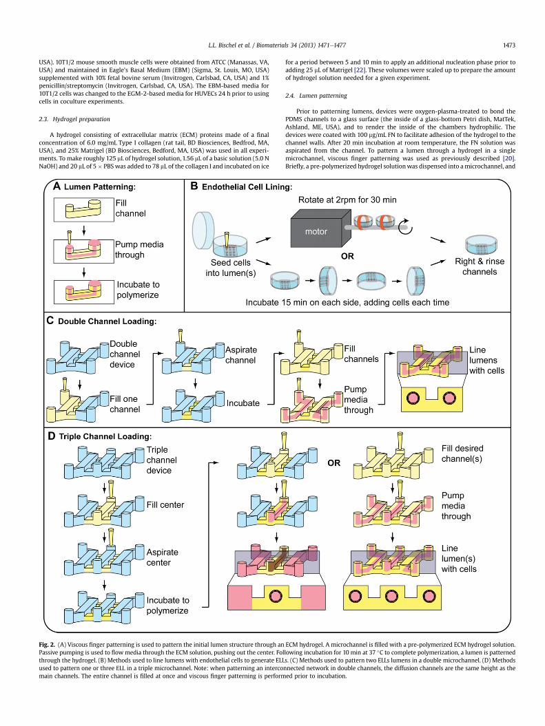
Endothelial structural integrity of the 3D ELLs was confirmed bythe presence of CD31 (or PECAM-1) at cellecell junctionsthroughout the monolayer (Figs. 3 and 4). To confirm properendothelial barrier function, permeability of the microvessels wasmeasured by flowing FITC-labeled BSA through the lumens of theELLs (Fig. 5A), and was found to be 4.73 (�0.75) � 10�6 cm/s,comparable to permeability coefficients found for other in vitroendothelial monolayers [25,27,28].
Vascular endothelial growth factor (VEGF) plays a role in vesselformation, endothelial barrier function, and is also known to induceangiogenic sprouting by stimulating tip cells that respond by
migrating up a VEGF concentration gradient [29]. To assess theresponse of the ELLs to a VEGF gradient, we performed a set ofexperiments in triple microchannels with an ELL patterned throughan ECM hydrogel in the center channel. We first characterizedgradient formation and stability using a 40-kDa FITC-labeleddextran as a model for VEGF. Dextran added to one of the sidechannels diffused from the source channel toward the sink channel,and developed a stable gradient afterw1 h that was maintained forat least 12 h (Fig. 5B). In practice, the gradient can bemaintained forextended periods of time by replacing VEGF and media roughlyevery 12 h [30].
We next exposed patterned ELLs to a VEGF gradient for 24 h, andobserved sprouting toward the direction of the VEGF source(Fig. 6A). Endothelial sprouts were found to express upregulation ofjagged-1, a known endothelial tip cell marker [31], compared tocontrol microvessels that were not cultured in the presence ofa VEGF gradient (Fig. 6B). When the gradient was maintained for48 h, there was a significant increase in the number of sproutscompared to control ELLs where no VEGF gradient was applied(Fig. 6C). Sprout length and sprout area were also significantlylarger in ELLs exposed to a VEGF gradient, compared to controls(Fig. 6DeE).
In addition to using the side channels to observe the effects ofapplied VEGF or other treatments to microvessels, the influence ofcocultured cells on the ELLs was observed. When 10T1/2 cells were
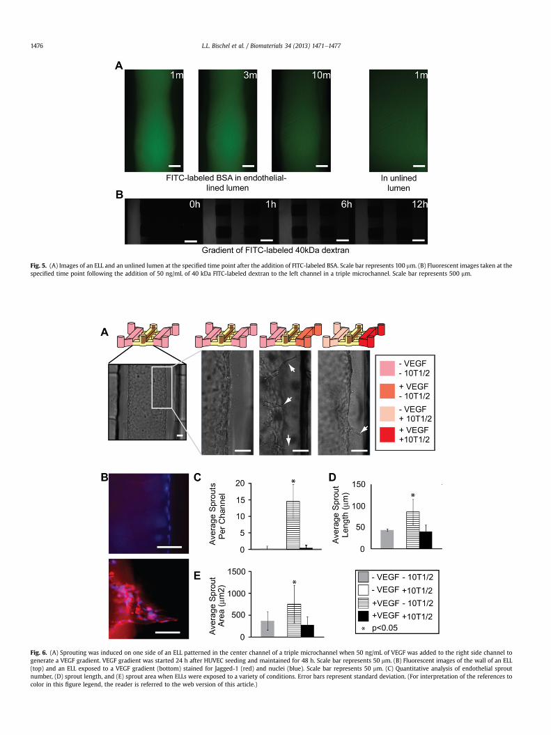
Fig. 6. (A) Sprouting was induced on one side of an ELL patterned in the center channel of a triple microchannel when 50 ng/mL of VEGF was added to the right side channel togenerate a VEGF gradient. VEGF gradient was started 24 h after HUVEC seeding and maintained for 48 h. Scale bar represents 50 mm. (B) Fluorescent images of the wall of an ELL(top) and an ELL exposed to a VEGF gradient (bottom) stained for Jagged-1 (red) and nuclei (blue). Scale bar represents 50 mm. (C) Quantitative analysis of endothelial sproutnumber, (D) sprout length, and (E) sprout area when ELLs were exposed to a variety of conditions. Error bars represent standard deviation. (For interpretation of the references tocolor in this figure legend, the reader is referred to the web version of this article.)
Fig. 5. (A) Images of an ELL and an unlined lumen at the specified time point after the addition of FITC-labeled BSA. Scale bar represents 100 mm. (B) Fluorescent images taken at thespecified time point following the addition of 50 ng/mL of 40 kDa FITC-labeled dextran to the left channel in a triple microchannel. Scale bar represents 500 mm.
L.L. Bischel et al. / Biomaterials 34 (2013) 1471e14771476
L.L. Bischel et al. / Biomaterials 34 (2013) 1471e1477 1477
cocultured in connecting side channels of a triple microchannelwith an ELL patterned in the center channel, and simultaneously inthe presence of a VEGF gradient, the number, length and area ofendothelial sprouts observed was markedly reduced compared toELLs in the presence of a VEGF gradient alone (Fig. 6CeE). This is ingood agreement with results presented by Chung and co-workers,who showed that coculture of endothelial cells with smoothmusclecells (10T1/2) reduced endothelial migration into a scaffold in thepresence of a VEGF gradient [16].
4. Conclusions
We have presented a simple method to pattern 3D lumenstructures through ECM hydrogels that can be lined with endo-thelial cells to mimic vessel structures in a variety of microchannelgeometries. We have shown that these methods offer the flexibilityto pattern ELLs in a variety of geometries on demand without theneed to redesign molds from scratch, an attractive feature notavailable with other recently developed methods used to patterncylindrical ELLs. Additionally, we have demonstrated the ability toadd reagents or different cell types in coculture with 3D ELLs. TheELLs in this system display normal barrier structure and function, aswell as expected response to VEGF treatment and coculture withsmooth muscle cells. The techniques described here offer a uniquebalance of accessibility, ease of use, and anatomical accuracy that isan improvement over current quantitative angiogenesis assays.
Acknowledgments
The authors thank Jacob Zimmerman and Neil Zimmerman forvaluable input in developing the motorized cell seeding option andErin Gemperline for assistance with image analysis. This work wassupported in part by the NIH grants R33CA137673 andT32HL007889, and the Korea Research Foundation Grant KRF-2008-220-D001331-019. David J. Beebe has an ownership interestin Bellbrook Labs LLC, which has licensed technology reported inthis publication.
References
[1] Carmeliet P, Jain R. Angiogenesis in cancer and other diseases. Nature 2000;407:249e57.
[2] Gerstner ER, Duda DG, di Tomaso E, Ryg PA, Loeffler JS, Sorensen AG, et al.VEGF inhibitors in the treatment of cerebral edema in patients with braincancer. Nat Rev Clin Oncol 2009;6:229e36.
[3] Chi AS, Sorensen AG, Jain RK, Batchelor TT. Angiogenesis as a therapeutictarget in malignant gliomas. Oncologist 2009;14:621e36.
[4] Jain R, Schlenger K, Hockel M, Yuan F. Quantitative angiogenesis assays:progress and problems. Nat Med 1997;3:1203e8.
[5] Auerbach R, Lewis R, Shinners B, Kubai L, Akhtar N. Angiogenesis assays:a critical overview. Clin Chem 2003;49:32e40.
[6] Young EWK, Beebe DJ. Fundamentals of microfluidic cell culture in controlledmicroenvironments. Chem Soc Rev 2010;39:1036e48.
[7] Barbulovic-Nad I, Au SH, Wheeler AR. A microfluidic platform for completemammalian cell culture. Lab Chip 2010;10:1536e42.
[8] Su X, Young EWK, Underkofler HAS, Kamp TJ, January CT, Beebe DJ. Micro-fluidic cell culture and its application in high-throughput drug screening:cardiotoxicity assay for hERG channels. J Biomol Screen 2011;16:101e11.
[9] Lecault V, VanInsberghe M, Sekulovic S, Knapp DJHF, Wohrer S, Bowden W,et al. High-throughput analysis of single hematopoietic stem cell proliferationin microfluidic cell culture arrays. Nat Methods 2011;8:581e6.
[10] Young EWK, Pak C, Kahl BS, Yang DT, Callander NS, Miyamoto S, et al.Microscale functional cytomics for studying hematologic cancers. Blood 2012;119:E76e85.
[11] Shao J, Wu L, Wu J, Zheng Y, Zhao H, Jin Q, et al. Integrated microfluidic chipfor endothelial cells culture and analysis exposed to a pulsatile and oscillatoryshear stress. Lab Chip 2009;9:3118e25.
[12] Young EWK, Simmons CA. Macro- and microscale fluid flow systems forendothelial cell biology. Lab Chip 2010;10:143e60.
[13] Young EWK, Watson MWL, Srigunapalan S, Wheeler AR, Simmons CA. Tech-nique for real-time measurements of endothelial permeability in a micro-fluidic membrane chip using laser-induced fluorescence detection. Anal Chem2010;82:808e16.
[14] Srigunapalan S, Lam C, Wheeler AR, Simmons CA. A microfluidic membranedevice to mimic critical components of the vascular microenvironment. Bio-microfluidics 2011;5. http://dx.doi.org/10.1063/1.3530598.
[15] Wong KHK, Chan JM, Kamm RD, Tien J. Microfluidic models of vascularfunctions. Annu Rev Biomed Eng 2012;14:205e30.
[16] Chung S, Sudo R, Mack P, Wan C, Vickerman V, Kamm R. Cell migration intoscaffolds under co-culture conditions in a microfluidic platform. Lab Chip2009;9:269e75.
[17] Song JW, Munn LL. Fluid forces control endothelial sprouting. PNAS 2011;108:15342e7.
[18] Meyvantsson I, Warrick J, Hayes S, Skoien A, Beebe DJ. Automated cell culturein high density tubeless microfluidic device arrays. Lab Chip 2008;8:717e24.
[19] Puccinelli J, Su X, Beebe DJ. Automated high-throughput microchannel assaysfor cell biology: operational optimization and characterization. JALA 2010;15:25e32.
[20] Bischel L, Lee S, Beebe DJ. A practical method for patterning lumens throughECM hydrogels via viscous fingering patterning. JALA 2011;17(2):96e103.
[21] Jo B, Lerberghe LV, Motsegood K, Beebe D. Three-dimensional micro-channelfabrication in polydimethylsiloxane (PDMS) elastomer. J Microelectromech S2000;9:76e81.
[22] Sung K, Su G, Pehlke C, Trier S, Eliceiri K, Keely P, et al. Control of 3-dimen-sional collagen matrix polymerization for reproducible human mammaryfibroblast cell culture in microfluidic devices. Biomaterials 2009;30:4833e41.
[23] Walker G, Beebe DJ. A passive pumping method for microfluidic devices. LabChip 2002;2:131e4.
[24] Fiddes LK, Raz N, Srigunapalan S, Tumarkan E, Simmons CA, Wheeler AR, et al.A circular cross-section PDMS microfluidics system for replication of cardio-vascular flow conditions. Biomaterials 2010;31:3459e64.
[25] Chrobak K, Potter D, Tien J. Formation of perfused, functional microvasculartubes in vitro. Microvasc Res 2006;71:185e96.
[26] Huxley V, Curry F, Adamson R. Quantitative fluorescence microscopy on singlecapillaries - alpha-lactalbumin transport. Am J Physiol 1987;252:H188e97.
[27] Mehta D, Malik A. Signaling mechanisms regulating endothelial permeability.Physiol Rev 2006;86:279e367.
[28] Zheng Y, Chen J, Craven M, Choi NW, Totorica S, Diaz-Santana A, et al. In vitromicrovessels for the study of angiogenesis and thrombosis. PNAS 2012;109:9342e7.
[29] Gerhardt H, Golding M, Fruttiger M, Ruhrberg C, Lundkvist A, Abramsson A,et al. VEGF guides angiogenic sprouting utilizing endothelial tip cell filopodia.J Cell Biol 2003;161:1163e77.
[30] Abhyankar V, Lokuta M, Huttenlocher A, Beebe DJ. Characterization ofa membrane-based gradient generator for use in cell-signaling studies. LabChip 2006;6:389e93.
[31] Sainson RCA, Johnston DA, Chu HC, Holderfield MT, Nakatsu MN,Crampton SP, et al. TNF primes endothelial cells for angiogenic sprouting byinducing a tip cell phenotype. Blood 2008;111:4997e5007.