tub shower oiverter valve commercial - … · (particulasdesoldadura,virutals de...
TRANSCRIPT

L-;
p~ge ITUB & SHOWER 190253A Oiverter Valve ~DELTAaCOMMERCIAL
RPI9653
': ...,
Complebl DlverterValveAssemblyDlverter StrUCtlJre Assembly
4
2 RPI8627 Extel'lder
~..-_ I· r I
---l7triEti--f
NOTE: No extension kit available to correct rough-in problems.
I IT4 Series Pressure On/unce Valve Only (Pre-1994)
NL.2.-
I L
;;;;;;;;;~;;::::::======-- ~I~
Flann with Gasket
Nuts S. Washers
Cartrldo Assembly
HiUlCIIe Screw ONLYHandle & Screw
VaIYe Body Cover & Partscoverp/ate Assembly(NOTAvailable)
Sleeve
RPI9655
RPI9652RPI96S4
RP/8543060255A
3
76
5 I 060017A I Handle Driver Assemb
5
.. I O6OO16A I HandleAssembfy
..
I TUB & SHOWER ACCESSORIES ISee Page 5

Pale ITUB & SHOWER II T5 Series Pressure Balance Valve Only (1994 on) ~DELTAaCOMMERCIAL
RP18213Screwdriver Stop Nsy.-WS Models Only
RP118RP1a630 (1" Longer)Screws
---- RP18l101ESCUlcheonRPa1130Eacu1cheon (RedlBlue Label)
RP18804 -------...,,/Carltklge Assy.-8S Plate
RP2003:llIT Copper SwBatPlug--Brasa
RP781/2" IPS Pipe Plug-8rass
RP4893Seets & Springs
RPat993-------{Plas1flr Guard/Thln WenMounting Bracket
niB &SHOWER ACCESSORIESSee Page 5
NOT SHOWN060 IS<4A - "Cambridge Brass" embossed Escutcheon.
2 Screws and Red/Blue label16284- 112" C X MIPAdaptor
~e Blede Handle WlScffNIi!'~RP8119 "SCrew

P~ge ITUB & SHOWER 76262 Wallmount Showerhead ~DELTA.COMMERCIAL
OLD STYLEBLACK PLASTIC
FLOW CONTROL(PRE.2000)
~//)(~
~~....~~~4~
? Discontinued - Available stock only
ITEM # ! PART # I DESCRIPTION
9 O6OO19A 1 Repair Kit - (9a) "0" Ring. (9b) Sprayplate, ('Ie) "0" Ring.(9d) Set SCI"l!W and Allen Key (not shown), (ge) Screw and Drive Bit(not shown), (91) "0" Ring. (9g) Screw, (9h) Control Body.(91) Black Plastic Row Washer - I of each except (9g) which is 2 per
10 0603 lOA RepaIr Kit - (lOa) "0" Ring. (lOb) Sprayplate, (I Oc) "0" Ring,(lOcI) Set SCI"l!W and ADen Key (not shown). (IOe) Screw and Drive Bit(not shown), (I Of) Screw, (lOg) Rubber Washer,(IOh) White Flow Llmlulr Disk - I of each except (I Of) which is 2 per
II 060311A Insert (for White Row Control) -
ITEM # I PART # I DESCRIPTION
I nl54-1 Anchorplate
2 107531 12.5 Degree Insert (for Black PIostk FII1W Control)
3 16271·1 Cap Screw
... O6OO28A Set Screw (12 per) and 5164- ADen Key (2 per) Kit
5 060020A Sprayplate (12 per). Screw (12 per) and Drive bit (I per) Kit
6 060~A Row Control. "0" Ring. and Insert Kit - I per
7 06014SA SCnlW' Kit (' 2 per) - no Drive Bit
8 76805 ? Row Control Kit

,\
I\
,\
I\~
__I
~..
._
_
I
Tfr
1--
-~--
--------=-==~t
~4t=---~--iE---=4J
$
1\
/I
II
,I
~
I~/~~~~bP~
ttJ~~\~~I
IF
eI
,1
lh--~~
~~eq
/V I\
"'0 ~ ~ (J) ~ o:J r m o z ~ G') m m

P~ge ITUB & SHOWER Tub 8. Shower Accessories 6)DElTA~COMMERCIAL
1 Discontinued -Available stock only
ITEM # i PART # I DESCRIPTION
1 9nol 610rnm (24") Handshower Slide Bar with Scf'eWll
060273A 762mm (30") HlIIldshower SlIde Bar widl Screws
060262A 1219mm (48") Haooshower Slide Bar with Screws
2 97101 610mm (24") HlIIldshower SlIde RaH with Screws
3 RPI2S04 Handshower WaBmount Bracket with Screws... RP7406 End<et to Hang Handshower on Sll~ BarsIRalIs
S RP31796 610mm (24" Stainless Steel Gr3b Bar with Adjustable Slide forHandshower
RP31797 914mm (36") Stainless Steel Grab Bar with Adjustable Slide forHandshower
6 RP32798 Adjustable Slide Only for Handshower
7 RP7-40S Handshower Head with Push ButtonWaw Saver Control
8 060312A Inarnm (70") White Reinforced Hanthhower Hose
93301 1750rnm (69") Chrome Double Spiral 8rau Handshower Hose
9 060252A Quick Disconnect Connector
10 765211 ASSE HandshowerVacuum Breaker
II 060303A Wallmount Supply Elbow and Flange for Handshower Hose
12 76262 FrontWallmount Shower~d (See l'a2t ., fOr ports breoJcdown)
13 76226 Shower Arm III'Id Set Screw Range
14 95801 Adjustable Volume Control
IS RP28601 Dual SprayToueh - Oean Shower~d
16 C70I83·2 Axed Spray Brass Showerhead
17 RP38357 Touch Clearl Showerhead
18 RPW66HDFl Vandal Resistant Showerhead - requires RP 13498 below for auembly to
Shower Arm
RPI34981 Spanner Wrench for RPW66HDF (not shown)
19 1902S3A DlverterValve for Multiple Shower OU1lets (See Page I (or parts breakdown)
20 060274A WaIImountThermometer Assembly
21 50343 Standard 1/2" IPS Dlverter Spout
RPS835 Optional S1lp-on Diverter Spout
2l Wnn4 Spout Nipple f1)r W76588 Tub Filler Spout
23 W76S88 Tub Rller SDout Only
'I..'..•....•...,....'"1
;''f'

WOODFORD
MODEL 241B241Y24 PARTS LISTITEM I PART# I DESCRIPTION
1 I 30009 Iwasher Screw
2 I 30008 Iwasher
3 I 30104 IOperating Stem
4 I 30105 IPacking Support Washer
5 I 30247 IEPDM Packing
6 I 30109 IPacking Nut - Chrome
I 30107 IPacking Nut - Brass
7 I 30120 IWheel Handle - Clear
I 30233 IWheel Handle - Tan
8 I 30121 IHandle Screw - Nickel
I 30002 IHandle Screw - Brass
9 I 34HF-CH I34HF Vacuum Breaker - Chrome
I 34HF-BR I34HF Vacuum Breaker - Brass
10 I RK-STK ITee Key
11 I B24BX IBox/Door Assembly - Chrome
I B24BX-BR IBox/Door Assembly - Brass
I B24BX-PB IBox/Door Assembly - Polished Brass
I B24BX-AL IBoxIDoor Assembly - Anodized Aluminum
I RK-24 IChrome Repair Kit (Includes items 1-8)
I RK-H34 IBrass Repair Kit (Includes items 1-8)
MODELB24Rough-In Dimensions
w7314" - -1Il.ET
3718"
Tc--3314"W.ll..l.ll1ICICMSS
END OFTHREAD
INMODEL 24
!---..f----f 33/8"
Manufactured under one or more of the following patents: U.S. Patents: 3,414,001; 3,543,786; 4,178,956;4,316,481; D216,790; D216,791; D277,365; D277,366; Canada Patents: 822,458; 852,529; 865,995
WOODFORD MANUFACTURING COMPANY2121 Waynoka Road, Colorado Springs, Colorado 80915 • Phone: (800) 621-6032 • Fax: (800) 765-4115
To view our complete product line visit: www.woodfordmfg.com or email: sa/[email protected] Division Of WCM Industries, Inc.

~DELTA.COMMERCIAL PLEASE LEAVE THIS
INSTRUCTION SHEET WITH THEINSTALLED FAUCET
54T1 A54T5 :t2>~A
WRITE PURCHASE MODEL NUMBER HERE FORFUTURE REfERENCE
ESCRIBA El NUMERO DEL MODELO COMPRADO AQUiPARA REFERENCIA FUTURA
POUR REFERENCE FUTURE, INSCRIVEZ CI-DESSUSLE N° DE MODELE DU PRODUIT ACHETE
BEFORE INSTALLING THE SPOUT OUTLET
Tum hot and cold inlet supply handles to the full open position. Holding the foot pedals down for full open position,flush out the lines for at leastone minute to dean outany construction debris (partidesofsolder, copperchips, pipe dope,teflon tape,etc.). Afterflushing, release the foot pedalsso valve will shut off and assemble spout outlet to thefaucet spout.
MAINTENANCE
When performing routine maintenance,do not void your warranty by Installing non-genulne parts. Use only authorized Delta Faucet parts. Afterany maintenance, remove the spout outlet, hold foot pedals down to the full open position. and flush lines for one minute. This will remove debrisfrom lines which can damage internal parts ofthe faucet and create leaks. After flushing, shut offwater at faucet and reassemble spout outlet.
CARE fNSTRUCnONSThis DaTA faucet is designed andengineered In accordance with the highest qualityand performance standards. With propercare,it will give yearsoftrouble free service. Care should be given to the cleaning ofthis product. Although its finish is extremely durable, it can be DAMAGED by ACIDIC
N a.EANERS (eg.deaners designed specifically for vitreous lavatories and water dosets), HARSH ABRASIVES or POLISH. To dean, simply wipe with a "Ill'o damp doth and blot dry with a soft doth. ....w C")
Wl.....-------------------------------------------~S~ N- S.II.P.J LAISSEZ CmE FICHE D'INSTRUCTIONS AVEC LA RDBINE7TERIE NOUVEllEMENT .TALliE
NCCo)Co)........
AVANT D'INSTALLER LA SORTIE DE BECToomer Ies monettes des amenees d'eaux chaude et froide a/0 position pleinement ouverre. Tout en retenant /es peda/es de commonde au pled enposition pleinemenr~ rinar Ies tuyauterles pour unep6ioded'au mains une minute,de fO{.on d ~/Imlner Ies debris de construction (particules debrasure,r6idus de cu/vre,pbte d'erancheltepaurjoints,rubon de Tef/OfIt etc.). Apffs Ie rl~ge,reldcher /0 "Malepourque Ie robinetse rerme et remonterIa sortie de beesur Ie bee de Ia robinetterie.
ENTRmENEn effectuonr de rentretien de routine, n'onnu!ez pas IIOtre gorontie en utilisont des pieces non d·origine. Utilise' seulement des pieces outorisees DeltaFaucet. A~s toutentretien, retirerla sortiede bee, tenir Ies pedales en position oboi$S~, et rincer /es ruyauwies pendant une minute. cedellminera IeSdebris des tuyauteriesquipourrolentendommagerlesoompasants internes des robinets et couserdes fuiles. Apffs lerincage. fermer /esrobinetsetrepIocerIa sortie de bee.
INSTRUCTIONS DE NETTOYAGECette robinetterie Delta Faucet a ere dessinee etc:onpse en conformile01« /es plus hours standards de qua/Ire etde performance. Un entretien adequatapportera plusieurs annees d'usage sans prob~me. Une attention particu/~n! devrait itre appartee au nettoyage de Cl! produit Bien que Ie fini soitextrhnement durable, IIpeur~e ENDOMMAGtpar des NEITOYEURS contenant des AClDES (ex: nettoyeul'S oon~s sp«ifiquement pour /es lavabos ettoilettesenpotce/ainevitrlfiee), desABRASIFSoupourlePOUSSAGE. Pournettoyer,essuyersimplement<M:?CunchHfon humideetQsskhet'al«unchiffondoux.
POR FAVOR DEJE ESTA HOJA DE INSTRUCCIONES CON LA LLAVE INSTALADA
ANTES DE INSTALAR LA BOCA DE SAUDADE LA ESPITAGin! las manijas de suministro de agua tria y caliente, a Ia posid6n CDlT1plemente abierta. Sujetando los pedales hada abaJo para obtener unaposici6n complemente abierta, deje carrer el agua por las Ifneas por 10 menos un minute para Iimpiar cualquier escombro de construcciOn(particulasde soldadura,virutAls de cobre,compuesto para tuberias,dnta tefIon.ete.) Despuesde dejar correr el agua,suelte los pedales de maneraque fa ~lvula seclerrey ensambfe la salida de la espita al tuba de salida de la "ave I grOO.
MANTENfMfENTOCuando hilga eI mantenimlento habitual, no anule su garantfa instalando piezas no-genuinas. Use s6lamente piezas autorizadas de Delta Faucet.Despues de cualquier mantenimiento,qulte la boca de salida de la esplta,mantenga los pedales hacla abajoen la posici6n completamente abierta,ydeje correr el agua por las lrneas por un minuto. Esto e1iminara escombros de la Iineas que pudieran daftar las partes intemas de la /lave ycrearfugas. Despues de dejar correr el agua con fa llave yensamble otra \'eZ la boca de salida de la espita de em.INSTRUCCfONES PARA EL CUIOADOLa lIave (grifo) de DElTA FAUCET est<i diseliada de acuerdo con los esti\ndares mas altos de calidad y funcionamiento. Con un cuidado apropiadodare atlos de servicio sin problemas. Debe de darle cuidado a la limpieza de este procIucto. Aunque su acabado es extremadamente resistente.puede ser DAf:iADO con UMPIADORES ACiOOS (ej.llmpiadores diseJ'lados epeciIicamente para lavabos vftreos de bal\o), ABRASNOS AsPEROS 0PUUMENTO. Para Iimpiar simplemente pasele un trapo humedo y seque con un pano suave.
lof4 203314 Rev. B
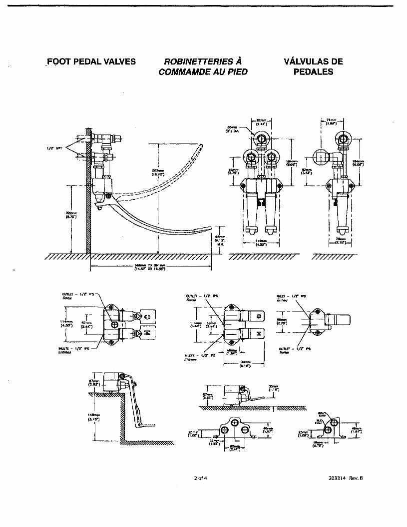
FOOT PEDAL VALVES.. . ROBINETTERIES ACOMMAMDE AU PIED
VALVULAS DEPEDALES
~~~I(2.U")
1111.
, I
f- 11_--1·-(4.liO"1
1-,7111'\"-jI cUd'} II
I
//7////////7///7 /7/7/7////
OOll£T - vr IPS-
~-(2.7l1')
-.1_
OUllEf - I/t: IPSSOIW
2of4 203314 Rev. B
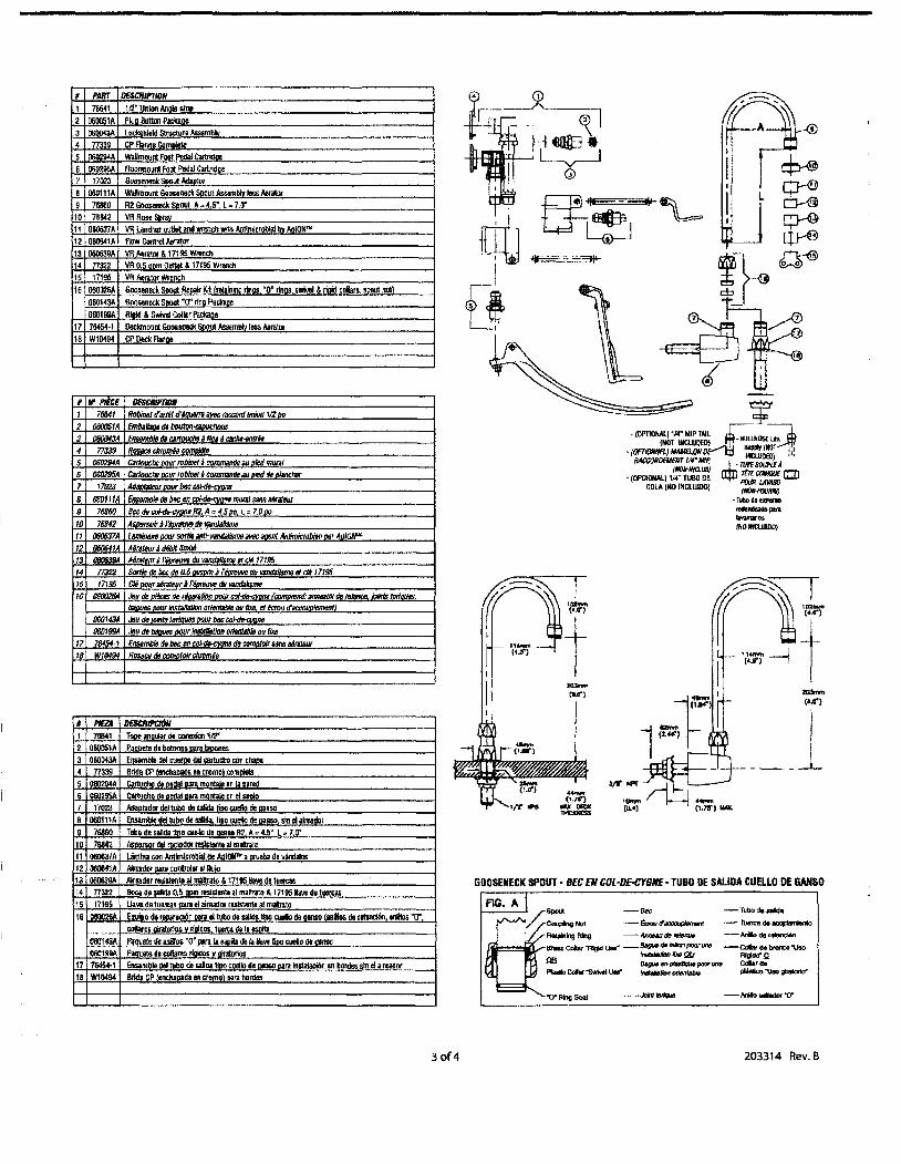
GOOSENECK SPOUT· BEC EN COL-DE-CYGIIE· TUBO DE SAlIDA CUELLO DE GAHSO
-(a.a'l
I!___ --L
......(',75'1 __
~- (OPTIONAL) 1/4' MIP TAIL ffi. alJilljQSE~
(NOT lIlCLUOE~L ....l.:J 5llpply I~~.:)tf• (0f'T1OIINfL} -aONvr .... 11lClU0Bl) !I~RA~:;': -.l: nMSOUI'lEA...L
• (OPCtONAL) 114" TlJBO DE 1IpJ:':'=~COLA (NO INGlUIDO) (NCHH'OOIiII/)
·T....d."'I_--ponIavaRWlO$INO 1NCUIIlO)
JD.Jon..
ru'l
II!
, f'lElA DESl:Ru>cmM1 76841 Tooe an!ItG' de conllllion 1/2'2 080051,1. P••""t. d. buIDn..am laoon""a 060043A Ensamble dtI .Il.'10 del cartudto tOIl cllaDa4 n:l39 BrId. GP fendlanad. e. cromo' ""mo","5 .Ol102!l4A !:aIludMl ... DodaI"', monlalo en Ii Dared6 060~9!iA Cllrtuch- ....- .... Ill...... en el suelo7 17em AlIaDIid... dol1llba d. Silida tioo aI8lIo de oansa8 O60111A EnsambIe del tubo de salida. lino ooetlo de aansa sin eI airoador9 7fl86O Tullo de salida till. tll6l1o de llalIID R2 A. 4.5' L. 7.0"10 76842 Moe""r dll r""iadOf reslitont. ~ mal!ratll11 0ll0e37A Urnina GOI1 Antltnlcroblal rio AtIlf1N1l' a ""'. d. '4ndalos12 060641,1. A1mador IWlI can1JoI.. eI ~itJ13 060639A AirBad.r r"'''''ole .. maJh"ato &17195 IIaYo de tuan:as14 n:l22 ~ dlllllda 0.5 com resi&t8llloal maI1mo& 17195 .... detuettali15 17195 L1a.. d.'.en:a, pall 01 airead'" resls1lln1t aI maJtrlta16 08002tiA Eoul 0 de ,llIIllrlICi6n .... e1llibo de sailda UIlD tII8IIo de oaII<O {mill.. de relinciiln dies "0"
collar.. -osvriGId... tuerca de lalSlll1aCB0143A PaauetJ: de iIliI/Oi "0' omli ...ila de Ii /Ia.. lioo .....0d. a.1ISG0601tl9A Paauoto d. cd1ares riaidos va_os
17 7645+1 Ensamblo del tuba de ..ada tioo cusllo d. gIllS(] om In!lalaoi6n .. bnnl.. sin lI,i,udnr18 W10494 llrida CP lencllanoda Oil cromol om bord..
," Prtt:E
OfBCIIIfflQII
1 76641 RolJInBt tfmlt d'4owmJ me raccorrJ IJtUon 112 Do
2 06005tA fmbo_ ds bouton""""""""
3 06IJIJ,/3A EI1S6IllbIB dllM1fouclM ano. dC8tIltI"61>11H4 77339 ROSICO cIlromdll~
5 IJ6D294A eattouche DOOr roiJineI.i CMIJIIaIld8 .. Died mUl1f/6 06IJ295A GaitouchB DOor ro_d_IJJJDiIId do JJhlnch1N
7 17023 AoiJtJl1lfJIDt 0DIIr bee coJ-dIJ.CVO/IB
8 IJ6Q111A ElJSombIe do bee f1I coHJe.cv""" JrIIJ(aJ SJ/IlS..atoll,.
9 76860 8ocdo cof-dt:-r:vun. liZ A. 4 51>0. L. 700010 76842 .AsiJorsoir j I'AontIJl//l d/J I'ilIIIJiIJsnm
11 000637A LamInaNe DOO' smti8 il/IIi-ViJ1HWismo ilIIIIC ""rmt Anlimic'obiOllOir Ao/ON"'12 -IA AdraJeu, ;I tI4/JIIl/mIlB13 0fIl1639A MIlIJeu"j1'_ dv vandaIIs"'" It c/O 1719514 T7322 SortIo d/J bee d/J 0.5 - ;11'- dv I/IIJ/Ja1I$m6 III eM 1719515 17195 CItJ 00tJ, _ratoo'.l ritHouve dv VlIICIi/I$mo
16 060026A JiJodt1-rkt 'col tid: anrra1IJ( """Is_.1Jaa.... /JmJr"'_O_DlIfIxt1 ottr:roud~mont
060143A JiJu do ioInlB lorioo.. DOVf btJc coI-tJrI-cvomJO601!l!lA JiJu de -...MIl, /IIsWIrtJon 0IIBn14bIa au lixo
17 76454-1 EIISIlfIllIItI 00 btJc ell col.",... do ctJmflhllt &IllS lira/Bur18 WI0494 lIosactiMI:tltMloIrcllirll>lh
# I'IlIlT DESCIIIPTION1 76641 112." Union Anale olllll
2 060051,1. pk;a 8tIttlJn Parlcaoe3 000043A Lockl;kleld SlnJ<tur. Assemb~4 77339 CP FlaMe ComAietl!5 II6fl2114A WlIImoont Foot Pedal Cartridoo6 0602116A Aoormoun! Fa>! Pedal GWidge7 17023 Goo..1MCIc iiooul AdiDlvr
8 060111,1. Wmoont GoQSllnecll Soout Astom~ .... _
9 761le0 A2 Go_od< 5000t ,1..4.5" t =7.lJ"10 781142 VA Roo Sorav11 OIlO637A VII Laml"" ou1lol and wrench with Antimicrobial bv AnION'"12 060641,1. flow Gornrol A.rator\3 060639A VR Aerator &17195 Wrench14 n322 VR 0.5 oortl Otl1lol &17195 Wrendl15 17195 VR lleator Wtench16 060026A 6oo....eck SllOOIllIloait Kit (r_llIll mos. '0' rInas. swM!l &riold calar sooutllllt\
C60143A Gooseneck 51lOO1 "0" nng Pacbce060199A Ri.1d & 8wM1 Collar Packaae
17 76454-1 IJeckrnount Ga08&D8llk SDou1 ~semblv loss ,\.ora10118 W10494 CP Oed< Aal1ae
30f4 203314 Rev. B

Delta Commercial Faucet Umlted WarrantyAn parts ofthe Oettae HDF" and TECK'" faucets are wall'ilnted to the original consumerpurchaser to be free from defects In ma~rla~ finish and workmanship for a period offive (5) years unless otherwise spedflcaJly stated in the catalogue and price book. This warranty is made to the original consumer purchaser and shaH be effective from dateof purchase as shown on purchaser's receipt.
Delta win. at its option, repair or replace,FREE OF CHARGE,durlng the warranty period, any part which proves defectlve In material Of workmllll5hlp under normallnstallatlon,use and waterand service condftions. If Delta faucet concludes that the returned part was manufactured by Delta Faucet and Is, in fact, defecttve, then Delta Faucet willhonour the warranty stated hen!in. Replacement parts can be obtained from your local deall!f or distributor listed In the telephone direcrory or by returning the partalongwith the purchaser's recelpt to 0Ul factory,TRANSPORTATION CHARGES PREPAID,at the ad<lress listed. TlflS WARRANTY IS THE ONLY EXPRESS WARRANTY MADE BY DEIl'A.ANY QAIMS MADE UNDER THIS WARRANTY MUST BE MADE DURING THE FIVE YEAR PERIOD REFERRED TO ABOVE. ANY IMPUEDWARRANTIES,INClUDlNG THE IMPUEDWARRANTY Of MERCHANTABILITY OF FITNESS FOR A PARTICULAA PURPOSE, ARE UMITED IN DURATION TOTHE DURATION OF THIS WARRANTY. LABOUR CHARGES AND/ORDAMAGE INCURRED IN INSTALLATION, REPAIR OR REPLACEMENT AS WELL AS INODENTAL AND CONSEOUENllAL, SPECIAl, INDIRECT OR PUNITIVE DAMAGES CONNECTEDTHEREWITH ARE EXCUJDED AND WILt NOT BE PAID BY DELTA FAUCET.
Some states do notallow limitations on how long an Impned warranty lasts,Of the exclusion or nmltatlon ofIncidental Of consequential damages, so the all<M: IImltations orexclusions may not apply to you. This warrantygivesyou specific legal r1ghts,and you may also have other rights which vary from state to state.
This warranty Is for COlTlITlefdal.products only from Delta Faucet Company and Delta Faucet Canada (a division of Masco Canada UmltedJ iIl'1d is void for any damage to thIsfaucet due to misuse.abuse, neglectaccident Improper installation. any use In vlolatlon of Instructions furnished by Delta Faucet or any use of replacement parts other thangenuine Delta parts.
Garantia Umitadade las Uaves deAgua Comerdales Delta
Todas Ia plezas de Iasllaves de agua (grlfosl Oel~ HDF-. 'T'ECI<'" est6n garantlzadils al cornprador consumidor original de estar Ubres de defectos de materW.acabado yfablJcad6n par un perlodo de dnco (5) aiios a menos que sea establecldo espedflcamenre de otra manera en el eatil.1ogo 0 libra de predos. Esta garantla se Ie hece alcomprador consumidor original y ser,\ efectlva desde Ia fecha de compra como IT1051Jlldo en el reclbo del compAdor.
Delta, a su opdOn, repariri 0 reernplazara,GRATIJITAMENTE,duran~ el perlodo de garantfa,cualquier pleza que pruebe ser cterectuosa en rnaterIaI 0 fabricacl60 bajoInstalad6n,usu, agua y condidones de servlcio norrnales. Sl Delta Faucet concluye que Ia pleza devuelta rue fabrIcada par Delta Faucet yes, de hecho,defectuO$il,entoncesDelta Faucet~ la garantfa establedda en este documento.
lasplezas de repuesto se pueden obtener de su comen:lante 0 dlstrlbuldor locallistado en e111breto telefOniro 0 devoMendo Ia p\elll junto con el reclbo del comprador anuestra fabrica,CARGOS DETRANSI'ORl'E PRE-PAGAOOS,a Ia dlrecd6n Incluida. ESTA GARANTIA ES LA UNICA GARAffflA EXPRESA HECHA POR DELTA. CUALQUJERRECLAMO HECHO BAJO ESTA GARANTfA DEBE SER HECHO DURANTE EL P£RfOOO DE CINCO AADs ARRIBA MENCIONADO. CUALQUlER GARAffflA IMPLfOTA.INCUJYENOOLA GARANTfA IMPLICITA DE COMERCIABIUDAD DE EMPl.EO PARA UN PROPOsllU PARTICULAR,TlENE UNA DURAOON UMITADA ALA DuRAOON DE ESTA GARANTfA. IDSCARGOS DE LABOR YIO DAOO INCURRIDO DURANTE LA INSTALA06N, REPARAOON 0 REPUESTO COMO TAMBltN DAfiIOS INODENTALES 0 RESULJANTES, ESPECIALES,INDlRECIOS 0 PUNfl1VOS RELAOONADOS CON to MENCIONADO SON EXCWIOOS Y NO SfRAN PAGADOS POR DIDA FAUCET.
Algunos estados no pennlten IImItadones de Ia durad6n de una garantla lmplfdta Ilmltada.0 Ia eJldusl6n 0 limltackln de dallos Incldemales 0 consecuentes,de manera quelas HmItadones 0 excluslones arriba mendonadas puedan no apllcarle a usted. Esla garantfa Ie da derechos legales espedfIcos,Yusted tambl«t puede tener otros clerechosque varian de estado a estado.
Esta garantla es solo para produetos comerdales de Delta Faucet Company y Delta Faucet Canada, una dMsf6n de Masco Canada Umltada.y es nula poreualquler daOOhechoa esta llave de agua resultante del mal uso,abuso.desculdo,accldente, InstaladOn incorrecta,eualquler uso en vlolad6n de las InstJuedones propordonadas par DeltaFaucet 0 cualquler uso de pIezas de repuesto que no sean de pIezas genulnas de Delta.
Garantie UmiteeDeltaComrnerdalToutes les pikes des roblnets de marque l)eltae HDFe etTECI(e sont gal'llntles contre tout dMaut de matl~,de f1nltion et de maln-d'oeuvre pour une ~rlode de dnq (5)ans,sauflndlcatlon contJalre stipu~ dans Ie catalogue et fa 1i5te des prix. Cette garantle est offerte ~ I'acheteur original et entre en vlgueur l compter de fa date dachatIndlquee sur fa preuve d'adlat.
Delta procedera,l son entI~discretlon,lla reparation ou au rernplar:ement.SANS FRAl5,durant Ia pe10de degarantle,de toute pike qulpresenteund~de rnatW!re aude maln-d'oeuvre dans des conditions d'Installatlon,d'usure,d'eau et de service norrnales. 51 0eIta Faucet d~rmine que fa pike retou~a~ fabrlquee par Delta Faucetet qu'en effect. eette pii!ce fait d«aut, Delta faucet respectenlalors /a garantle stIpulee aWlpr~ Les pieces de rechange peIM!ht @tie obtenues chezvotre marchandlocal 011 Ie dlstributeur Insaltdans votre annuaire t~onlque,OIl en retoumant la pl«e alnsl que Ia preuve d'achat ~ notre uslne, fRAIS DETRANSPORT PR8>AY£S, ~radresse lndiqu6e. CETTE GARANTIE EST LA SEULE GARANTIE EXPRESSE FAITE PAR DELTA.
TOUTE ROCtAMATION FAITE EN VERTIJ DE CETTE GARANTIE DOlT £TR£ PR6ENTtE DURANT LA PelIODE DE ONQ ANS MENTIONEEE CI-DESSU5. TOUTE GARANTIE IMI'UClTE,YCOMPRJS LA GARANllE IMPUCITE DE VAlEUR COMMalCIAlf RELATlVEMENT ALA FONCTJON, EST UMITEE EN TERMES DE DURa POUR LA DUR££ DE CETTE GARANTlE. LESFRAIS DE MAlN-D'OEUVRE ETJOU DE DOMMAGES ENCOURUS DURANT L1NSTALLATION, LA Rffi\RATION au LE REMPLACEMENT AINSI QUE LES DOMMAGES-lmRtTsACCESSOtRES OU lMMAttRIELS,SPKIAl1X,INDIRECTS OU PUNmFS~ RAPPORTANT SONT EXCWS ET NE SERONT PAS PAvB I'I'R DELTA FAUCET.
Certains~ ne pernlettent pas fa limitation de la dlrie de fa garantle lmpIIdte, au fexduslon ou la limitation des dommages-in~ acces50ires au ~rlels, et parconsequent,les Iimitatlons OIl les exclusIons stIpu~ cl-dessus pelM!nt ne pas s'appllquer dans votre CBS. Cette garantie vous accorde certains drohs reconnus par la 101 etIIOUS avez peut.«re auss! d'autnts d",1ts qui varientd'un em Afautre.
Cette garantle s'appllque seuJement lUX prodults commerciilUX des~ 0eIta Faucet et Delta Faucet Canada.une flBaIe de Masco Canada Umlted et est nuNe de pleindroit pour tout dommage cau~Ace ",blnet en raison d'usage excess!f,d'abus,de ~enee.d'accldent,demallVaise instaflatlon, tout usage en contraYl!t1tlon desdirectives fournles par Delta Faucet au tout usage de pikes de rechange autres que des pikes orlllinaies Delta.
Delta Faucet Canada, a division of Masco Canada LimitedBox 5750, 420 Burbrook Place. london ON, Canada N6A 4L61-80Q.567·3300 EngrlSh 1-80Q.26S-9245 French
Delta Faucet CompanyBox 40980.55 East lllth St Indianapolis, Indiana, USA 46280(317) 848·181 2
For further technical assistance call Delta Commercial Technical Service at 1-800-387-8277
TECK~
www.deltafaucet.com
4of4 203314 Rev. B

Models/Mode/os/Mode/es 585LF-V & 585LF-VCSLPU Series/Series/Seria
, RP50151., Handle with button & set: screw for 585LF-VCSLPU, Manlja con batOn y tomillo, de presion para 585LF-VCSLPU
Poignee avac vis de calage: ~t,~ulo." pour 585LF~V~~LPU
..,
RP46391Button & sat screw •
• Boton y tornillo de presi6n •Bouton et vis de calaga '
, RP47263.Handle wi1h button & setscrew for 585lF-VMantja con bOton y tornillode presiOn para 585LF-VPoignee avec vis de calaga ,at bouton pour 585LF-V
::'RP46391' "" .. " ":~• Button & set screw ,I~, Baton y tornillo de prasion~ Jo<Y"........ 1
, Bou:on at vis dacal~g,,~ _ ...'.~~
.' RP34404....;--- ~; Cap ~,Casqueta ~
~ ;~~~;'~:~itStop & e..' Ceramic Cartridge ..~ Butae at cartollche en cerarnique -,Topa del limite rotacional y ,
" Cartucho de Ceramica .'co
Grail® Single-Handle Lavatory FaucetRobinetterie de Toilette aManette Simple Grail®Llave Monomando Grail" para Lavamanos
:RP197S4...·--.--:·..:..',:....::.,.:.. 'C;'-"-"~~:r
"Aarator-1.5 gpm (5.7 UM)Aireador-1.5 gpm (5.7 UM)
: Aerateur-1.5 gaVmin (5.7 UM)
RP47302",---'~---.-L-~~1II
; Base & gasket :• Base y empacadura ,
Base et joint
,, RP47300-"------c Hoses I
. ManguerasBoyaux
"'Specify finish / Especifique el Acabado / Prec;sez Ie fin,

C")C")CD"lit0N
C")C")
!N
C")C")
®!N
SINGLE HANDLE LAVATORYCENTRESET FAUCETS
LLAVES MONOCONTROLDE MONTURA DE CENTROPARA LAVAMANOS
ROBINETS A ENTRAXECOURT A UNE POIGNEE
N
~DELTA.0
tww
COMMERCIAL
~ <I- f§t ASME0\112.18.1IC6o\Sl25.1W ASME 0\112.18.21 C6o\ 1112S.2w
ModelsIModelosiModeles
N501-HDF-DST,511-HDF-DST,
0 515-HDF-DST, 516-HDF-DST,t 520-HDF-DST, 523-HDF-DSTw Series/Senes/Senaw
©N
Wlbpun:tl-.d mocI8I ___.....
Q Escrlt.......--dII.........-..pndo..... 1nIcrIvG.................1cLcoWw
You may needlUsted puede necesitarlArtldes dont yous pouvez avoir besoin:
I 1~~ /~~/For easy Installation of your Deltafaucet, you will need:
• To READ ALL the instructions completelybefore beginning.
• To READ ALL warnings, care andmaintenance infonnation.
Para lostalacl6n tacit de su lIave Deltausted necesltani:
• LEER TODAS las instrucciones completamente antes de empezar.
• LEER TODOS los avisos, cuidados, einfonnaci6n de mantenimiento.
Pour installer votre robinet Deltafacilement, vous devez :
• LIRE TOUTES les instructions avant dedebuter.
• LIRE TauS les avertissements ainsi quetoutes.
US. Pal 4,218,785; other patents pending.
204833 Rev. A

II PositIon falJcet (1) l!lI1d gasket (2) on sink.Secure faucet 10 sink with mounting nuts (3).Tighten securely by hand. Option:"$ink isuneven. use sIIIoone IHIder the gasket
B Stal1(larrl Con,lCctlons
Ensure all flttlngs and end conneclions are free ofdebris. Faucet 1Itlings (1) we 318· compression,with ends COIouIed red for hot and blue for cold.Loop tubing (2) If It Is leo long. Noc.~Recommended tubing minimum bend dIameIlIr Is 8".Secure melal nut (3) on faucet tube 1D supplyvalve connection (4) and hand lighten, thentighten one additional tum v.rith wrench. DO NOTOVERTIGHTEN. Repeal ror olher nme.WARNING: Do not II8e pipe dope or atlI4Ir_Iants on water line connections.
Standard ConnectionsConexlones Estandare~
Branchclllcnts Standal cl
B C;uslOIll Fit COIlIlOc!,O"S
NOTICE: Ifyou delermlne the PElt supply tubing forthI8 faucet III too long end mlDt be lIIlon8f to__an acceptlIble InstallaUon, be sure to Nad ttMtInstructions and plan ah..t. When cutting thesupply tubing, the instaler~ the /'IIIIfIOIl8IbIIltyto do so In a.." thIltau_ a IeIk-fnle joint to becreated. Delta Is not ....ponslble for tubing that Iscut too short 01' cut In a way that win not allow for aIeak..free joint.For cus1Dm lit instalatlons, you must use RP50952.s'leeves supplied wIIh model and nlll:ll included on supplylines. Tube cut must be lltrIllght. see plasllc sleeveinstallation instructions foUnd In RP50952 and includedIn 1h18 document (page 3) for more iIlfonTWllon.
Secure metal nut (1) on faucet tube In supply vaJveconnection (2) and hand tighten, lhIIn tigh1Ien M addllion8l2 lI.mS with wrench. DO NOT OVERTIGHTEN.Repeat for other tube.
Custom Fit ConncctlOnsConexlOnes Especl31esBranche'11ents Speclaux
Pof8ntIIII Problems and Remedies• Tubing .. not cut perpendicular to the am. ofthe tub: carefully make an additional cut, beingcareful not 10 cut the tube 1Do short
• Tubing .. cut too 8hort buy a coupl1ng unionand a replac:emllnl supply line tIllll mate togetherfran S store. The c:oupling union end Intended Inconnect In the fl!Iucet must mete In the standllrd318" connection nuts and pIa8tic sleeves sUppliedwith the faucet.
• The pIutlc &Ieeve or connection nut 1lI1ost::purchase a repIacBment nut and/or plastic sleevethatare designed In seal with PEl< WIling.NOTICE: DO NOT UN I metallleeve. RPa1243gak8t (supplied with faucet) or ferrula In theplace at tha plullc lIIH¥e suppIIecI, It may notemu I ....."..joint. WARNING; Do not usepipe dope or other....... on water lineconnections.
II COloque la lIaw (1) V Ell~ue (2) en ellavamanoe. ~ conlUelcaa (3). 0pci6n: Siellevemanos estll desrIIveIado. use siIic6ncJebajo del empeque.
8 C0l19XIoncs Estandarcs
AsegOn!lse que 1Dd0ll10ll aceeecrio8 VI.oonexlones finales esIBn libRls de residU08. Losaooasorios (1) son de compresilln de 318", con1011 axlrtllTIo8 de c:oIor rojo paIil el agua C8Ilen1e Vazul p8"8 Ell agll&l frie. Enlaoe las tubarfas (2) aies muy Iatga. Nota: II curva mlnlma I'lICXlrII8ftdada 88 de 8- de dl6metro. Flja Ie tuercll deITllll8I (3) en el tuIlo de la IIave de ague a Is conexi6n (4) Vapriete a mano, kIago aprelale conuna vueI1II adic:lonal con una Ibm! de tueroas.NO APRIETE DEllA8IADO. Rapila con el otrotuIlo. A\IISO: No !We COIIIpIIeSto pari tubeIfalIII otroa selladores en Ia~ de IetuberIa de agll..
II Placar Ie roblnet (1) et Ie Joint (2) SIB' revier.Fixez Ie robinet II ralde des ecrous (3).FscuIIatif: Si fa SUffaoe der~est 1nBga1ll,p/acez du comp0s6 d'MancIJeite ~ Ia siliconeSOlIS 1e}Olnt
As8weZ-YOiI8 que lctis Ies raocords son!~de corps etrangars. le bianchement est effectu6au moyen de raccords de robinettarle (1) 318 po acompression. L'llXlnlI1I9mlle du racc:ord d'eaucheude est rouga et celie du ra<XlOItf d'eau ti'okfeest bleu. Faites una boucle avec Ie tube (2) s'U88t Irop long. Nota: le dI8mMra minimal de Iecourbunl dolt OInt d'liU moIns 8 po.~l'ecrou m6lalIque (3) que aI trouw sur Ie nme durobinet, sur Ie raccon:l du robinet d'lIIimentllllon(4) et serrez-le ill Ie main, puis faites un tourauppl6meotalre avec una cl6. PRENEZ GARDEDE TROP SERRER. Racoordez Yautre tube de Ismllme 1T1lIIll8re. liSE EN GARDE: N'utAisezpas de pile 6 joint nl d'autres prodUItsd'6tanc:h6flj sur lea IliCCOi'ds de tuyaull8rle.
B :::C·,CX'0I10S ESPSCI818S
A\IISO: 8I1.-llld dsl8rmIna que II tubarIa PEX para ..eumlnlstro de ague pari este 11_ de agua ..muyIMg8 Ydebe~ pare _rune 1nstetec16naceptsble, -ut1.-eIeer..I~y PlanIflque de antemano. CIJlIIldo COfte II tubel'la delumlnlstro el instal8dor ecepIa III respoMabilkledde hecerlo de une manera que pennltle _runeartIeul8cl6n sin tIItracio_. Deb no .. nasponubIID par" tuberIaa que Ie hen corfado doli'lDiafoCClitIlI 0~ de _1IllUI8I'8 que no penn'" _lIitIculecl6n llbre de Mraci6n.Pllre Inslalaclonea hechas a Ia medida, usted debe usarrnangas RP50952 Incluides con eI modeIo V las tuarcesincluldaa en las tuberfas de sumlnistro. El corte del tubodebe..recto. Vee lasI~par Is inSlalaci6nde Ia manga pi{IstIcs lncIuida con eI RP50952. Vparam8B Informaci6n Incluida en esl8 docurnen1o (pelglna 3).Flje la tuerca de malal (1) en Ie lubeIIa de Ie lIave deeguafgrifo a Ie conexi6n de Ie vilIvule de suminilltro (2)aplet8 s mana, entonoes apriete 188 2 welllIs adidonlIIescon Ie 1IlMl. NO APRIETE DEMASIAOO. Repi1a con Iaotratuberfa.
NOIlFICATION : 51 Ie tube d'aUmentallon en PEX dece roblnet est trop long at dolt Mre n;c:courcI, I....les'nstnM:tIons lit prenez Ie temps de r6ft6chlr.Vous devez couper Ie tube de manI6re • obl8nlr IIi'Ijoint 6tlIncha. Delta n'aceept& eucune .-ponsabIIIt6 II Ie tube s ti coupe trap court au d'lInemanillre qui empIche Ie Joint d·.... 6bInche.Dans Ie cas des il1lllBll8ttOnS sur mesure, yous devezutirtser Iell manch0n8 RP50952. lbumls~ Ie robinetat lea 9cttxI!; qui seliouvent sur lesanf~ d'811u. Letube doit 6lre coup6 d'6quetTe. Pour otlIenir plus derenselgnements, wullllz consulter lea instructionsd'ill8lallalions des manchons en plastique qui setrouvent dans Ie kit RP50952 et qui soot incIusas dansIe Jrisent document (page 3).
\fl9sez /'4k:rou m6IaIlique (1). qui Be trouve aur Ie tubedu IOblnat, sur Ie raccord du robinet d'almenlallon (2)at aerrez·1a aIe main, serre;z: aIo<s IelI 2 tDurs lldlIllonnelsavec Ja cl6. PRENEZ GARDE DE TROP SERRER.Raccordez "autre tube de Ie m6ma rnaniere.
2
PrQ~ PoIBncIaies YSoIuciOl*• LIl tuIIerfa no wtlIr co;tada pefpIlIldlculiir eI eJede .. beIIera: aJi<Iado88mentB haga un corteIdlclonal. tenlendo cuklado de no cortar el tubodama8lado corto.
• La tuberf8 estt COI1lIda damesl8do corta:CClIllJRl en un elmacen un acopIamienlo de uni6nVuna tuberfa de suminislro de repueslD que acoplan. EI exlnlmo de Ie uniOn de acoplamienlD que88 panl conectar a Ia llave de egus debe acoplarcon las tuerea8 esl6ndare8 de 3/8" Ymanges depl(Islico Incluklas con la lIaWl de agus f grlfo.
• LIlllMlnga pl6stlca 0 Ie tuen:a de conexI6n saha perdido: compre una tuen:a de repuasto VlorT1lrogII pl8&tiCII dI8enada para eellar con Is tubelfaPEl<. AVISO: No ...... _nga de metal,RP51243 empaque (sumlnlstrado con .. grIfo)o casquQIo, en vez de Ie mllllglinclulde puedeno c,..- una artleulecl6n ., ftltnlcl6n. AVISO:No use compuesto pa.- tube.... u 0b'0S ....dorw en las cone:lllo.- de Ie tuberfe de ag .
Probl6rnel1 possibles et correctifs• Le tulle n'est pea coupe d'6quelT8 : FalI8s unenculMlle coupe en prenanl gerde de ne pas trapraccourclr Ie tube.
• You. 1iV8Z coup6 Ie tube trap court : AchelBzun raccord-UI1lon et un tube d'arrtv6e d'eau darechange dans un magasln. L'IiIlCln!ImitiI dura<:lXlItkmion II raccorder au roblnlll dolt etrecompatible avec las 6aous 318 po standard et Ie6manchofIs en p/astique fi:lumls avec Ie Itlbinel.
• Vous _ penlu IIi'I manchon en plaslque auun 6crou de~nt:AdleteZ un ea-cuelIou un manchon en p1astiqUll CORP pourformer un racoortI 0bmChe avec un tube PEX.NOTIFICATION: e:vItIez d"u1111l1er un menchonm....llqUe, RP61243 Ie joint (foumle avec Ieroblnet) au line Y1role ... place du manchonen plastlque fouml. Le Joint lie 88,. pea6tanche. MISE EN GARDE : N·u1111l1ez pas depOW • joint III d·....,... prockJlIs d'6tanch6lt8sur'" raccorda de tuyilul8rle.
204833 Rev. A

Custom Fit Connections· Plastic Sleeve Ins'allatlon InstructionsConcxlones Espcclales Instructions d installations de la manchon ell plastlqueSpCCI3UX Blanc!lcment - Instrucclol1es pala la InstalaclOn clel'a Manga Plasllca
ColT8et methodMetodo CorrectoBonne m6thode
1. Identify desired length of tube (1). Leave 1'·2" ofexlra length to allow lor easierInstallation and cut tube. Ensure cut is slraIght and burr free.
2. Slide nut (2) and plastic llIeeve (3) onto cut tube. Ensure 81_ is oriented as shown.
3. Insert tube into outlet filling (4). Tube shOukl tou<:h bottom of hole inside fitting.
4. Slide plastic sleeve down lube until I! engage6lllp of filling. NOTICE: Fall... to usepIastk: sleeve In the correct orlenIatIon will result In dleconnecllon and poIlllIbIewater dllllalJlt.
5. SlIde nut 0V&r pIasIic sleeve. IJ'Imh wrench, tighten nut 2 tLms past finger tight.
1. ldentifique 18 Iongitud de&eeda del tuoo (1). Deje 1'·2' de soIlura para una Instalacl6nmas fl!K::lI ysin rebabas. Asegure que eI corte sea recto ym nobabas.
2. Reale Ie tuerca (2) Y la manga pIntlca (3) sobl& al tuoo cortado. Asegure la mangasa orients segtln 10 demostrado.
3. Introduzca el tubo dentro delecceaorio (4). EJ tubo debe tocar eI fonoo del agujerOdentro del accesono.
4. Desllce Ie maoga plas1Ica hacia abejo en el tubo ha8la que encaje ella parts~del aooesorlo. AV\SO : EI no uaer Ia mange pIiIItIca en Ia orientacI6n c:orrecIareau!tarA en deeconexl6n 'I poelble daIlo pol' lIlIua.
5. De8ltce Ie tuerca sobre Ia mange p/8stk:ll. Con Ia nave de tueroas, apriete Ie tuercad6ndole 2 vuellas mas de 51 fuera apretado 8 mano.
1. ldentlftez Ie longueur desirile du tube (1). L.ais8ez 1 il2 pouces de Ie longueur supplementalre pour faclIlter "installsllon at ooupez Ie tube. Faltes una coupe d'ilquerre etenlavez Ies bavul&8.
2. Glissez fecrou (2) et Ia ITIIIOCtIon en plastJque (3) sur Ie tube coupe. Assurez Ie manchonest orientB comme montre.
3. Introdulll8Z Ie tube dans Ie racoord (4). La tube doit toucher Ie fond du trou a flnterieurdu raceord.
4. Faites glisger Ie manchon en p1astique dans Ie tube jusqu'il ce qu'it~ OOIl8Ia p&Il!asupilrieure du raccord. NOTIFICATION: Sl Ie manc:hon en ptastlque n'a pes'"Install6 daM l'orIentation c:orrecta. Ie raccord peut.. d6f8lre et reau peutOCC8lIIoRner de.~
5. Feltes gissar recrou sur Ie manchon en pIaslique. 5errez-le AIe main, puis fa/telI deuxtours a "aide <tune cle.
3
Incorrect InstallationInstalacion IncorrectaInstallation Incorreete
Do not install s/eeIIeupside doNn.
No Instale Ie mangeboCa abajo.
N'ln8ta11ez pes Iemanchon iI renvers.
Do not use RP51243 gasket(1) supplied with PEX tublngor braes ferrula (2) suppliedwith valve stops.
No.-RP51243~(1) eumlnistrado con IIIwberla de PEX 0 eI casquillode bronce (2) surnlniatradocon las v61vutas de cIerre.
N'utIlisez pas RP51243 Iejoint (1) foumie IMlC Ietuyaul8rie de PEX QU labegue en allvnl (2) fournieIMlC Ies robInets d'arTit.
EI1lIU'8 cut Is straight.
Aseurez-vous queIa coupe est droite.
Ensure tube Is fultvI~Into stop befo!B sidingsleeve down to engage topoffilllng.
Aeegurese que eI tubo esteoompIatamenIe introducidodentIo del tope antes dedeslIzar Ia manga hadaIlbajo p8fll ancaj&r Ie partesupel10r del accesorio.
Aseuraz-1/llU8 que Ie tubeest Introduit entiefementdans Ie robinet d'an6t avsrtde falre gil_ie _nchon\l8rs Ie bas pour Ie fixer lliIe per1le flUIl8rleura duraccord.
-:204833 Rev. A

Offset TailDieceTuba de eola AcodadoRaccord de v1drange c:oud9
Grid Flange--...........:::~Blida de III RllJll1aBride de <:repine
~ Thin Abre Gaskat~~quedeAbre DeIgada
;-----Q' Joint mince en fibrae
GasketEmpaqueJoint .
~
33T290Complet8 Offset Grid Stralner Assembly (with overflow holes)EnslUnbie Completo del Colltdor Aeodado con Rejilia (con huecos paradesbord..)Cr6pine c:oucl& complile (avec orifices de trop-pIeln)
33T290-1Complete Offset Grid Strainer (no overflow holes)Colador Acodado con RejUIa Completo (sin huecos para desbordes)Cripine couds complete (sans orifices de trop-pIeln)
RP61aa--------~~TailpieceTuba de ColaRacoord de vldange droit
RP6346Complete Grid Strainer AssemblyEnsamble Completo del CoIador con RejlliaCripine compl8te
RP6140""""'=-------..........llCNut &W8sherTuerca y ArandelaI:crou et rondalle
~ ~~PesIa/\aIRebordeSlide de cr8pine
Rf>6142 -J~Gasket ...
Jo~ ®
Grid Strainer InstallaQon1. Remove grid flange. Screw nut and wa&her down as far as possible.
Push gasket down to nut and washer.2. Remove tailpiece and apply Tenon-' tape to threads. Replace taIlpiece.3. Apply silicone sealant to underside of grid flange. Insert grid slrainer
assembly up through bottom of lavatory. Screw grid ftange back onanc:l sewre.
4. Pull grid strainer straight down into drain hole and sean gasket nut andwasher. DO NOT TURN GRID STRAINER WHILE TIGHTENING NUTOR SEALANT MAY NOT SEAl.. DRAIN. REMOVE EXCESS SEALANT.
Offset Grid Strainer Installation1. Remove grid lIange and thin fibre gasket.
:z. Insert grid f\ange and thin fibre gasket down into the lavatoryfrom the top.
3. Assemble thick rubber gasket onto grid flange and l?QeNi gridflange into offset tailpiece assembly.
Instalaci6n para 18 ReJl1Ia CoIadora (Flltro)1. Quite la pestailalreborde. Atomille Ia tuerca Yla arandela 10 mas que
pueda. Empuje Ell empaque hacia la tuerca y Is arandela.
2. Quite la plezade cola Yapllque cinta Tenon- a 'as roscas. Coloque lapieza de cola de nuevo.
3. Aplique sellador de silicOn a Is parte interior de la pestaIIa de Ie reJilla.Intraduzca el ensemble de Is rej~1a coIadora a trav8s de la parte deabajo dellavamanos. Atornile Ia pes1afta de Is reJiHe de nuevo yasegurela.
4. Hale la rejilla dlrectarnerlte hacia abajo haste Deger dentro del hoyo dedesagOe y asegure el empaque, Is tuerca y Is arandeIa. NO GIRE LAREJILlA COLAOORA MIENTRAS APRIETA LA TUERCA 0 ELMASTIQUE NO SElLARA El DESAGOE. QUITE EL EXCESO DEMASTlQUE.
Instalaci6n de CoJador Acodado con ReJil1a1. Quite Is brida de Ia rejills y Ell ernpaque de fibra delgada.
:z. Introduzca la bride de Is reiilla y el empaque de fibra delgadsdesde arriba del JaVlllTlBnos en dilllCCi6n haclaa~.
3. En&amble el ernpaque de goma gruesa en la bride con rej~1a
y atomIHe Is bride con rejille en Ell ensamble del tubo de cotaacodado.
Installation du renvoi1. Retlrez Is collerette du renvoi. Vissez I'ea-oo contre Is rondeIle pour
abaisser ces deux etBments aulant que possible. Placez Ie joint contre/8 rondelle et fecrou.
:z. Retirez Ie raccon:I de vidange at et appliquez du ruban de TeflorJe surlas filets. Remettez ensuile Ie racx::ord en pIaoe.
3. AppIiquez du~ d'etancheitl! a Is silicone contra Ie dessous dela collerette. Introduisez Ie renvoi par Ie dessous du lavabo. VISSeZ Iscollerette sur Ie renvoi pour Is caler.
4. Abalsser Ie renvoi dans Ie trou de vidange dU lavabo et f1xez-te enserrant 1'6crou contra la rondelle et Ie joint EMP£CHEZ LE RENVOIDE TOURNER PENDANT QUE VOUS SERREZ I.'ECROU POUR NEPAS COMPROMETTRE L'EFFICACfTE DU COMPO& D'ETANCHEIT1:.ENLEVEZ L'EXCES DE COMPOSE D'ETANCHEITE.
Installation du renvoi adouble coude1. Retirez Ia collerette du renvot elle joint mince en fibres.:z. Par de dessus du lavabo. pIaoez Ie coIlerette munie du joint en
fibres dans Ie lrou de vldange.
3. Par Ie dessous du lavabo, p1acez Ie joint en caoutchouc llpaiscontre la collerette at vissez la colIerette dans Ie raceord devidange.
4 204833 Rev. A
DesagiieAutomatlco de Metal1. Quite e1tap6n y eI reborde. Atomille la llIerca completamente
hasta abajo. Empuje la arandelafroldana y eI hacla.2. OUite eI tuba de coIadel aJ8fllO, apllque c1ntaT~, coloque
otra vez el tuba de cola.3. Aplique 8iIic6n a /a parte interior del reborcle. Inserte el aJerpo
en eIlavamanos. Atomlle el rebordlllln el euerpo.4. B pivote debe de ester de frente a la dave. Hale eI ensamble
hacia abajo flnmemente y auJeteio en siIIo. NO LO GIRE.5. Apriele Ia tuercaJarandelalempaque, Iimpie el exceso de
sllic6n. NO LO GIRE.6. Quite Is tuerca del p1vote. Inslale la barra horizontal y eI tap6n
como desmontable 0 1Ijo. Apfiete a mano la tuerca del pivots.7. Una la barre horizontal a la barra chala utilizando eI gancho.
Instale Ia barra de aIzar. aprlete eI tomlHo. Conecte eIensemble al desagiie.
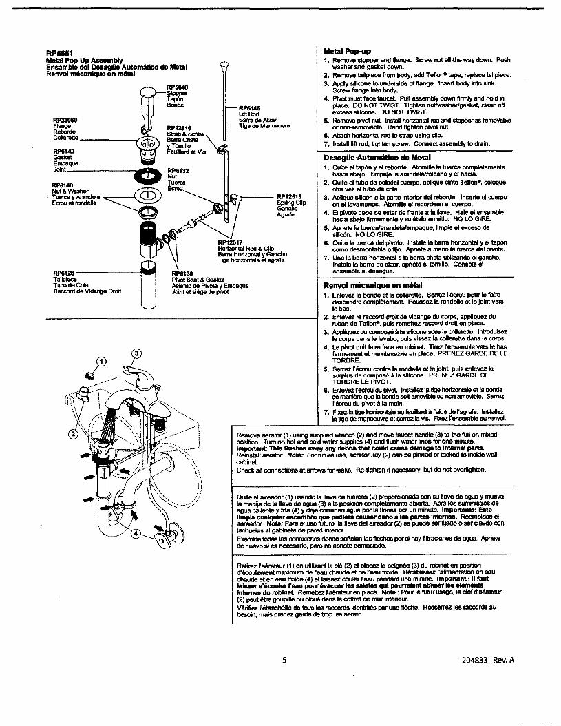
Metal Pop-up1. Remove stopper and flange. Saew nut all the way down. Push
washer and gasket down.2. Remove tailpiece from body, add Tefton-tape. replace tailpiece.3. Apply silicone to underside of flange. Insert body Into sink.
saew flange Into body.4. Pivot must face faucet Pull asaembly down firmly and hold in
place. DO NOT TWIST. Tighten nutlwashetlgasket, clean offexcess slicone. DO NOT TWIST.
5. Remow pivot nut. Ins1aI horizontal rod and stopper as Itlmovableor non-removable. Hand tighten pivot nut.
6. Attach horizontal rod to strap using dip•7. Instal 11ft rod, Ughten screw, Connect assembly to drain.
Renvoi mecanlqu8 en metal1. EnJevez la bonde et la coIerette. Serrez 1'9I;rou pour Ie faire
descendre complelement Poussez Ia rondelle et Ie joint veraIe bas.
2. Enlevez Ie raocord droit de vtdange du corps, eppllquez duruben de TeflorTt', puis remettez raccord droit en place.
3. AppIiquez du compose a Ia silitme sous Ie coIerette. Introdul8ezIe corps dans Ie lavabo, puis v1ssez la coIlerette dans Ie corps.
4. Le pivot dolt falltl face au robinet TIT8Z I'ensemble vers Ie basfannement lit malntenez-te en place. PRENEZ GARDE DE LETORDRE.
5. Serrez reaou contre Ia randalle &lie joint, puis enlevez '11surplus de compose a la sUicone. PRENEZ GARDE DETORDRE LE P1VOT.
6. Enlevez reaou du pivot. Instalez 18 Uge horlzontale at Ia bandade mani8re que Is bonde soit amovibIe 011 non amovible. Serrezrecmu du plvol aIa main.
7. FIxez Ia Uge horizonlaIe au feuIard araide de fagrafe. InstalezIa Uge de Ill8I\OO\Me et serrez Is vis. FIX8Z fensernble au reovoL
RP61ACilift RodBarra de POwTlge de Manoeuvre
Quite eI aireador (1) usando la llave de tuercas (2) proporcionada con su nave de ague y muevaIa manija de Ia llave de ague (3) a fa posiciOn completamente abierta Pbra los sumlnistros deagua caIlente y frfa (4) y deje lXlIT8r en ague par Is lfneas par un minuto. Importsn1e: EatoIImpla c:ualquler esc:ombro que pudlera causar dello a las partes int8l'11U. Reemplace eIaereador. NotlI: Para eI usa futuro, la Have del aireador (2) se puede ser fijado 0 ser davdo (Xlntachuelas al gabinete de parad Interior.Examine todas las conexIones donde sellalan las flechas par si hay flltraclones de agus. Aprietede nuevo si es necesario, pero no aprlete demasiado.
Remove aerator (1) using supplied wrench (2) and move faucet handle (3) to the full on mixedposition. Tum on hot and cold water supplies (4) and flush waler lines for one minute.Important: This f1us'- B'IfIf1 any debris that could cane damage to Intemal parts.Reinstall aerator. Note: For future use, aerata key (2) can be pimed or tacked to inside wallcabinet.Check all connections at arrows for leaks. Re-tighten if nece&S8I}', but do not overtighten.
1'161.\)---..----- RP12518SprIng ClipGanchoAgrafe
RP12517Horizontal Rod & ClIpBarra Horizontal y Ganchonge horizontllle et 8grafe
RP6130Pivot Seat & GasketAsienlo de Plvote y EmpaquaJoint et siege du pIVot
3
RP6128-------i'l~TailpieceTullo de ColaRac:cord de Vidllnge Droit
RP5651Metal Pop-Up AssemblyEnsamble del DeaagOe Autornatlco de MetalRenvoi m6canlque en m61a1
....... rrr==~ ~~ ~k......-,..~-----~ 9aI1'llChata
'Q!P' YTornilloRP6142 Feuillartl et VISGasketEmpaqueJoInt ~ RP6132
RP6140 ....., ~ercaNut & Washer~ Ecrou. Tuen:a y ArandelaEcrou &l rondeIIe
Retirez faerateur (1) en utilisant la cI8 (2) at pIacez fa poignee (3) du robinet en positiond'6couIement maximum de reau chaude at de "eau froide. RBlabIissez ralimentation en eauchaude at en eau frolde (4) et laissez ocular feau pendant une minute. Importsnt: II tautlalsaer s'8coullll' 1'lIIIu pour evacuer las sa1et6s qui pourralent abtmer lee elementsInternes du robinet. Remellez raerateur en place. Note: Pour Ie futur usage, Ia cIet d'allraleur(2) peut 6tre goupillit ou doue dans Ie coIfret de mur interieur.Verifiez I'etanchllite de tous les raccords identifies par une fttlche. Resserrez les raa:ords aubesoin, mais prenez garde de trap les serrer.
5 204833 Rev. A

1
I······ "-"'1'"I. I. ~
l ~ f ,=='\ " I ,"'="
, , fIE" . , ;-" , , ," , • I" ". ," " ,
" f",.. ... '\'t' I,J.- \11 I
1:L
2
Setting The Handle Umlt Stop (Optional)This faucet includes an integrated handle limit stop that has two positions.Position 1, 10 the left, allows full handle motion (the full range between("all cokf to 'all hof). The faucet is set in position 1 in the factory.Position 2, to the right, allows half of the normal handle motion ('all cold'to 'mixed hotIaold").
The handle limit stop can be adjusted by the homeowner once the fauoetis installed. setting the handle limit stop in position 2 may help to preventscalding because it lirrits the amount ofhot water in the mix; however,
FIJando la parada de Ilmlte de la manija (opclonal)Esta llave de agua incluye una manija integrada, que tiene dosposiciones, para limitar Ie temperatura. La posiciOn 1, a fa izquierda.permIte eI movimiento completo de la manija (e1 a1cance completoentre eI ague 'totatrnente fJfa" hasta "tolaImente caliente"). Laftiblica preselecciona la lIave de ague (grift!) a Ia pD6ici6n t. Laposici6n 2, a fa derectla, permite la mitad del atcance de movimientonormal de la manija rtotalmente frla" a la posici6n 'mixta caliente!tria").
Una vez Q1Je Is have de ague (grifo) se ha instalado, el limiterotacionaI de la manija pusde ajustBrse por eI propietatio de faresidenda. Ajustando Ia manija de ajusIB del tope del limite de
Pla~nt l'al1'lt de limite de poIgn6e (facultatlf)ce robinet est munl d'une but8e de temp6rature maximala ~ deuxpositions. La position 1, agauche, permet Ie d8p1acament de lamanette entre Ies deux extremitBs de Is pIage de templlrature (eautres froide et eau tres chaude). C'est la position sillectionnee enuSlne. La position 2, adroite, permet Ie dSptacement de Ia manettesur Ia moitie de fa plage de temperature (eau tres froide at eaumltig6e).
11 est possible de regler Is but8e de ternp8ratpse maxirnale de lamanette au moment de 1'lnstaHatlon du robinet. Un reglage a laposition 2 peut emp&her 1'6bouillantage parce que oette position
6
this handle limit stop will not always prevent scalding because It doesnot compensate for incoming pressure or sudden water temperaturechanges.
To change position of the handle limit stop: remove the handle;move the valve stem to the all cold posltion 80 the water is on; changethe position of the handle IImit stop; tum off the water; reinstaB the handle.
fa~re a fa posici6n 2 puede ayudar a prevenlr escaldadurasporque limits fa canlidad de agua caliente en la mezda; sin embargo,esta manila que IIm1ta la temperatura del ague no siempre prevendrttescaIdaduras porque no compensa la presi6n del ague de entrada 0cambios repeI'lllnos de Is ternperalura dal ague.
Para camblar 1alI poslclones de Ia manlja que Ilmlten Ia IIImperatura:quite Ia menija; camble Ia posici6n de la espiga de Is valvula a fa pos1cl6ntotaImente frla de manera que eI ague este abierta; camble la posicl6nde la manija que limita Ia temperatln; carre eI agua; reinstate Ia manija.
limite Is quanlitB d'eau chaude dans Ie millange. Tou1Bfois, ce regiage deIa butlle de temp6rature maximale de la manette ne constitue pas unegarantie absoIue contre I'ebouillantage perce qu'li n'offre surone protectioncontra Ies fluctuations de la pression d'alimenlation au les changements detemperature soudains.
Pour modifier Ia position de Ia bu1lle de temperetunl mllldmale de Iamanette ; enlevez Ia manalte; amenez fobtu!8teur arextremite de faplage du cOte eau froide pour faire s'eoouler I'eau; modifiez la position dela butlle de temperature maximale; fermez Ie ratlinet; reins1allez Is manette.
204833 Rev. A

RP54687EIJow Handle & set ScrewManija del Codo Y TomIIlo de AjusteManette de Coude et VIS de Cslaga
~RP51503BonnetBoneteChapeau
~----IRP51502cap
Casquflk>Errtlase
--==-.............,------RP52834HOF Handle & Set ScrewMllnija HDF TomiIIo de A/uSfIManellB HO'et Vis de Carage
RP15~setScrewTomifIo de Ajus1eIlls de Calage
~------061035A
Set Sa'ew (pkg of 3)Tomillo de Ajuste (pkg de 3)Vis de C8lage (pqt de 3)
RP50587------~Valve AssemblyEnsamble de Ia ValvulaSoupape
RP5342!9---------t~Adaprers ~::=~: ~~~:: 1~=~ ~~~ 0Ariaptadors ~318"-24 UNEF ID 1/2"-20 UN &318"-24 UNEF to 112"-14 NPSMAdapteurs 0: :~: ~~~~: ~~:~ ~~~ 0
061037A0.5 GPM (1.9 L) Spray outletwith Aerator KeyBoca de SalIda del RocIadorde 0.5 GPM (1.9 L) Y U811& deAIt8ador~de 0,5 gallmin(1,9Iitre1min) et Clef d'aArateur
~RP60729... 0.5 GPM (1.9 L) Spray 0ulIet
Boca de SBIida delRociadorde 0.5 GPM (1.91.)Pulverisateur de 0,5 gallmin(i,e IitreImln)
~--061038A
Aerator Kev (for use withRP60729 ;; ~P60983)LIave de AIreador (para etusa con eI RP6Q729 &RP6OP83)Clet d'atlralelM" (pour utiliseravec RP60729 et RP60983)
RP60983-----_1.5 GPM (5.? L) PressureCompensating Aeretor (PCA)Aiteador COInpenS8C/or de /efX8s1OO (ACP) de 1.5 GPM (ti7 L)Aersleur pour compenser la pression(ACP) de 1,5 gal/min (5,? litre/min)
RP535311--------------,l.Dcknuts (2)Contratuen:as (2)ECIOU8 de B10caga (2)
\i~~~~- 06103eAGasketEmpaqueJoint
......Q-RP50952~ PIastk: Sleeves
Mangas Pl8sticasManchona en Plastique
7 204833 Rev.A
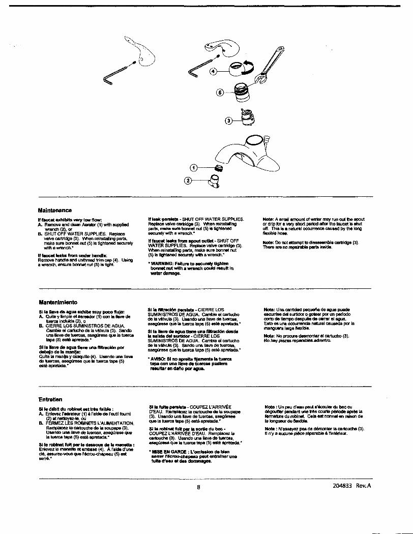
Maintenance
If faucet exhibits very low flow:A. R8IT1OW and clean AImItor (1) wittl8UPPIied
wrench (2), orB. SHUT OFF WATER SUPPLIES. Replace
vatve cartridge (3). When reinstalling parts,make SUi'll bonnet nut (5) Is tightened securelywith B wrench."
If faucet "akll from under handla:Remove handle and unthraad trim cap (4). Usinga WI'lIIlch, ensure bonnet nut (5) is light
Mantenlmlento81 fa \lave de agua exhIbe muy poco flujo:A. Qulle y Rmpie el aereedor (1) conla Haw de
hHlrca incluld. (2), 0B. CIERRE LOS SUMINISTROS DE AGUA
Cambie eI cartucho de Ia Wlvula (3). 5andOuna 11&1/8 de tuen.as, asegUrese que Ia tuereatape (5) es16 8Pretsda."
$11. 1\alIe de agua t1ene una ftItracI6n pordeb8lo de fa 1IIlU11ja:Quits Is manljs y caaquilio (4). Usando una lIavede tuert:aa, asegurese que Ia tueroa taps (5)..tit apretada."
"Entretien
$lie dtblt du roblnat.. tr6s falb1e :A. Enlavez fa6rateur (1) aI'alde de 1'(lUlU fouml
(2) et nettoyez..., OUB. FERMEZ LES ROBtNETS t'AUMENT~nOtt
Remplacez Ie cartouche de Ie aoupape (3).Uaando una ,lave de 1uarcas, 2l98gureae queIe tuen:a tapa (5) este apretadll.·
$lie roblnet tuft par Ie~ de la IIllIIl8lte :Enlevez Ia manette at emba8e (4). Afalde d'unec16, asaurez-vous que 1'6croLH:hllpeau (5) eatsene."
If leak pelSlstI· SHUT OFF WATER SUPPliES.Replace valve CllI1ridge (3). When I'lIlnstalnngparts, make sure boMet nut (5) is tightenedS8CUl'lIly with a wrench."
If faucet IeIIkII fmm spout outJet • SHui OFFWATER SUPPLIES. Replace valve cartridge (3).\MIen l'lIinsbllRng parts, make sure bonnet nut(5) Is tightened sea.araIy with a wrench."
"WARNING: FaHuN to securely tightenbonnet nut wIttla wreneh coutd ....ult Inwater damage.
Sila IlltnIcI6n perslstB. CIERRE LOSSUMINISTROS DE AGUA Carmie el cartuchode 18 wlwls (3). Uaando una llave de tuerc:aa,esegtftse que Ie hHlrca tspa (5) eatit aprelada."
SI la IhMt de lIgUa tIane una flltracl6n desdefa salida del surtIdor • CIERRE LOSSUMINISTROS DE AGUA. Gamble el cartuchode Ie v6lVula (3). S8n<Io una lIave de tuerl:.aa,asegurese que la tuerca tapa (5) eatit apretada."
• AVISO: 81 no apreIta f1jllJll8llt8la tuercatapa con una llava de tuan:M pudleraresuItlIr en daflo par agua.
S11a tulte perM1e • COUPEZ L'ARRIVEED'EAU. R8/11lIlICeZ Is ClII1DUChe de Is soupape(3). Usando unellave de tuercas, aseglnseque Ie tuen:a tapa (5) este apretada."
$lie robInet full p!w Ia sortie du bee •COUPEZ l'ARRNEe O'SAU. Remptacez /sClII1DUChe (3). Usando una IIlIve de tuerca.s,asegUrese que lIl1uerca tapa (5) este apretsda."
• NIlE EN GARDE : l'omlsslon de bienaan-er1'6crGlJ.d\apeau paul entralner unefulte d'aau et detl dommages.
8
Note: A small amount of watsr may run out the spoutor drip for a YeIY short period after the 11woet Is shutoff. Thi8 is a natural occurrence cauled by the longt1exible hose.
Note: Do not attsmpllD disassemble cartlidge (3).There al'll no repUable parts iMide.
Note: Una cantJdad paquel\a de lIQua puedeescurrise del surtldor 0 gole8r par un perlodooortD de tiIImpo deapU6s de oerrar e1l1QU8.Esto ea una occurrencia naturet caueada par Iamanguel'lliarga flexible.
Nota: No prncue desmontar el cartucho (3).Nohay piezas reparabIes .adrentro.
Nota : Un peu d'eau paul s'iK:ou,-" du bee oud6goutIer pendant une lr6s cour1e pc\riode spree lafermeture du roblnel Cola est normal en raison dela longueur du IIexIble.
Note: N'esaayez pea de d8ma11er Ie callDuche (3).II n'y a eucune pJ6ce rBparable • l'lnt8rleur.
204833 Rev. A

---------------------------- ------
Delta Commercial Faucet limited WarrantyAll parts ofthe Delta. HDFCI andTECKCI faucets are warranted to the original consumer purchaser to be free from defects In material,finish and wor1<manship for a penod offive (5) years·unless otherwise specifically stated in the catalogue and price book. This warranty Is made to the anginal consumer purchaser and shall be effective from dateof purchase as shown on purchaser's receipt
Delta will, at Its option,repair ar replace, FREE OF CHARGE.dUring the warranty per1od,any part which proves defective in material or workmanship under normallnstalIation,use and water and service conditions. If Delta Faucet concludes that the returned part was manufactured by Delta Faucet and is, in fact,defective, then Delta Faucet willhonour the warranty stated herein. Replacement parts can be obtained from your local dealer or dlstrlbutor listed in the telephone directory or by returning the part aloogwith the purchaser's receipt to our factory,TRANSPOflTATION CHARGES PREPAID,at the address listed. THIS WARRANTY ISTHE ONLY EXPRESS WARRANTY MADE BY DELTA.1'J'lYClAtMSMADE UNDERTHIS WARTlANTY MUST BE MADE DURING THE AVE YEA~ PERIOD REFERRIDTO AlroVE.1'J'lY1M1'UED WARRANllES,1NClUOlNGl1iE lMPUEDWARRANTY OF MERCHANTABILITY OF FITNESS FOR A PARTICULAR PURPOSE,ARE LIMITED IN DURATION TO THE DURATION OF THIS WARRANTY. LABOUR CHARGES ANDIORDAMAGE INCURRED IN INSTALLATION. REPAIR OR REPLACEMENT AS WELL AS INCIDENTAL AND CONSEQUENTIAL, SPECIAL., INDIRECT OR PUNITIVE DAMAGES CONNECTEDTHEREWITH ARE EXCLUDED AND WILL NOT BE PAID BY DELTA FAUCET.
Some states do not allow limitations on how long an implied warranty lasts,or the exclusion ar limitation of Incidental or consequential damages, so the above limitations orexclusions may not apply to you. ThIs warranty gives you speclflc legal rlghO, and you may also have other rlghts whICh vary from state to state.
this warranty is for commercial products only from Delta Faucet Company and Delta Faucet Canada (a dMslon ofMasco Canada UmitedJ and Is \/Old for any damage to thisfaucet due to misuse, abuse, neglect,accident, Improper installation, any use In violatlon of instructions furnished by Delta Faucet or any use ofreplacement parts other 1f1angenuine Delta parts.
Garantla Umitada de las Uaves de Agua Comerdales Delta
Todas las p1ezas de las Haves de agua (grifos) Delta-H~,TECK't estlin garantizadas al comprador consumldar original de estar Iibres de defectos de materlal,acabado yfabricaci6n par un perlodo de cinco (5) ailos a menos que sea establecido espedflcamente de otta manera en el eat.llogo 0 libro de preclos. Esta garantla se Ie hace alcomprador consumidororiginal y ser;i efectIva desde la fecha de compra como mostJado en el redbo del comprador.
Delta, a su opcl6rt, reparara 0 reempiazanl,GRATUITAMENTE, durante eI perlodo de garantfa,cualquler p1eza que pruebe ser defectuosa en material 0 fabrlcad6n bajoinstalad6n,usu,agua y condiciones de servIcio normales. Sl Delta Faucet conciuye que la pieza devuelta fue fabrlcada par Delta Faucet Yes. de heche, defectuosa, entoncesDelta Faucet honranlla garantia establedda en este doc:umento.
Las plezas de repuesro se pueden obtenerde su comerdanre 0 dlstrlbuidor Iocallistado en ellibreto telef6nko 0 devoMendo Ia piela junto con e1 redbo del cornprador anuestra f;ibrka,CARGOS DETRANSPORTE PRE-PAGADOS, a la dlreccl6n Inclulda. ESTA GARANll"A ES LA UNICA GARANTlA EXf'RESA HECHA PeR DELTA. CUAlQUIERRECLAMO HECHO BAJO ESTA GARANTfA DEBE SER HECHO DURANTE EL PERfOOO DE ONCO Atilos ARRIBA MENCIONADO. CUALQUIER GARANll"A IMPLICITA, INCLUYENDOLA GARANT!A IMPL1cITA DE COMERCIABIUDAD DE EMPl£O PARA UN PROPOsITO PAtmCULAR,nENE UNA DURACION UMITADA A LA DURACION DE ESTA GARANTfA. LOSCARGOS DE LABOR Y/O DA~ INCURRIDO DURANTE LA INSTALAOON,REPAAACION 0 REPUESTO COMO TAMBltON DAIiIOS INCIDENTALES 0 RESULTANTES, ESPECIALES,INDIRECTOS 0 PUNIT1VOS RELACIONADOS CON LO MENCIONAOO SON EXCLUIDOS YNO SERAN PAGADOS POR DELTA FAUCET.
Algunos estados no permiten Iimitaclones de Ia duraci6n de una garantia Impllcita Iimitada,a Ia exdusl6n 0 Ilmltad6n de danos incidentales 0 consecuentes. de manera quelas IImltaclones l) exclusiones arriba rnencionadas puedan no aplkarle a usted. Esta garantfa Ie da derechos legales espedflcos, y usted tambh!n puede tener otros derechosque varian de estado a estado.
Esta garantfa es solo para productos cornerclales de Delta Faucet Company y Delta FaucetCanada, una dMsl6n de MascoCanada Umitada,yes nula por cualquler dallohecho a esta lIi111e de agua resultante del mal uso,abuse, descuido,accldenle, instalaci6n incorrecta,cualqu ler usa en v1olaci6n de las instrucciones propordonadas par DeltaFaucet 0 cualquler usa de plezas de repuesto que no sean de p1ezas genulnas de Delta.
Garantle Umtie Delta CommercialToute5les pieces des robinets de marque DeltaC1 HDFCI etTEQ<1II.50nt garandes contre tout dt!faut de mati~e,de Rnltfon et de main-<:f'oelwre pour une pSiode de cinq (5)ans, sauf Indkatlon contralre stlpu~ dans Ie catalogue et Ia liste des prix. Cette garantle est offerte aI'acheteur original et entre en vlgueur acompter de la date d'achatindlquee sur Ia preuve d'achat
Delta procedera, ~ son entiere dlsaetlon,~ Ia reparation ou au remplacement. SANS FRAIS, dur.mt la periode de garantie de toute ~ce qui pr6ente un detaut de rnatl~reoude rnaln-d'oeuvre dans des conditions d1nstallation. d'usure.d'eau et de service normales. 51 Delta Faucet determine que Ia piece retournee a ere fabriquee par Delta Faucetet qu'en effect,c~e pl~e fait detaut, Delta Faucet respectera alors Ia garantle stlpulee aux presentes. Les pieces de rechange peuvent ~re obtenues chezvotre marchandlocal au Ie dlstrlbuteur Insent dans YOtte annualre tl!k!phonique,au en retoumant la piece alnsl que la preuve d'achat ~ notre uslne, FRAlS DE TRANSPORT PRtPAVEs, ~Yadresse Indiquee. CErn GARANTIE EST LA SEULE GARANTlE EXPRESSE FAITE PAR DELTA.
roUTE RKLAMATION FAITE EN VERTU DE CETTE GARANTIE DOlT mE PRBENTtE DURANT LA Pt:RIODE DE CINO ANS MENTIONtE CI-DESSUS. TDUTE GARANnE IMPUCITE,YCOMPRIS LA GARANTIE IMPLICITE DE VALEUR COMMERCIALE RELATlVEMENT At:APTlTUDE ALA FONCTlON, EST LIMITe: ENTERMES DE DU~E POUR LA OU~E DE CmEGARANTIE.
LES FAAIS DE MAIN-D'OEUVRE ET/OU DE DOMMAGES ENCOURUS DURANT L1NSTALLATION, LA R£PARATION OU LE REMPLACEMENT AINSI QUE LES DOMMAGES-lNTI:RITSACCESSOlRES OU IMMATtRIELS, SPtClAUX,lNDIRECTS OU PUNmFS S'Y RAPPORTANT SONT EXCLUS ET NE SERONT PAS PAvEs PAR DELTA FAUCET.
Certains ~ats nepermettent pas fa limitation de la duree de Ia garantle Implicite,ou I'exclusion ou la limitation des dommages-lnter~ accessolres ou Immaterlels,etparcoosequent,les limitations au les exclusions stlpulees cl-dessus peuvent ne pas s'appliquer dans votre cas. Cette garantle vous accorde certains drolts reconnus par fa 101 etvous avezpeut~ aussi d'autres drolts qui varlent d'un etat II Yautre.
Cette garantle .'appllque seulement aux produits commerciaux des societes Delta Faucet et Delta Faucet Canada, unefdiale de Masco canada Umlted et est nulle de pleindroit pour tout dommage cause ace roblnet en raison d'usage excesslf,d'abus, de negllgence,d'accldenr,de mauvalse Installation, tout usage en contravention desdlrectlves foumies par Delta Faucet ou tout usage de pieces de rechange autres que des pieces originates Delta.
Delta Faucet Canada, a division of Masco Canada limited-BOl( 5750,420 Burbrook Place, London, ON, Canada N6A 4L61-800-567-3300 (English) 1-800-265-924S (French)
Delta Faucet CompanyBox~,55 East 111m St., Indlanapolls,1N,U5.11..46280(317)848-1812
For further technical assistance, caH Delta Commercial Technical Service at 1-800-387-8277.Para la asistencia tecnica adicional, servicio tecnico Comercial del Delta de la Hamada en 1-800-387-8277.Pour obtenir de I'assistance technique, appelez Ie Service Technique de Delta Commercial au 1-800-387-8277.
lECK'www.deltafaucet.com
9
s~select..com
204833 Rev.A

Notes I Notas I Notes
----------

<!l
-.-LEONARD___ WATER TEMPERATURE CONTROLS
INSTALLATION ADJUSTMENT SERVICEHIGH-LOW MANIFOLD
TM-2020BValve assembly is ASSE 1017 listed e
Valve assembly is CUPC listed ~c"-=%
IMPORTANT! Provide serial numbers for both valves when ordering parts!!Small valve manufactured after July 2007 starting with serial # TM26272
INSTALLATION
Bulletin G-IIE
June 2009
DOMESTIC OUTLET
i
e
RAt.. fL.
J, ..IJ~ ,
5:J~tn
DOMESTIC OUTLET
i
I.//~-_ ...~- t t
HOTINLET COLD INLET
,IHOT INLET
'\COLD INLET
1. Type TM manifold systems are factory pre-assembledand tested and include large and small thermostatic watermixing valves which function as a system to meet bothhigh and low demand for tempered water.
2. System should be installed at a location where it caneasily be cleaned, adjusted or repaired.
3. System supplies must be connected as shown (Hot-left,Cold-right). Exercise caution when soldering.
4. Flush pipes thoroughly after system has beenconnected.
5. If this assembly is installed on a recirculated hot watersystem it MUST be piped according to LEONARD'SREQUIRED PIPING MEmODS (see pages 4 & 5).
6. Refer to page 3 of this bulletin for correct SetupInstructions.
Maximum Operating Pressure 125PSI (860 KPA) for Hot and Cold Water.
CAUTION
All thermostatic water-mixing valves have limitations. They will not provide the desiredaccuracy outside of their flow capacity range. Consult the capacity chart on page 8. Minimumflow must be no less than as shown.
1360 Elmwood Avenue, Cranston, RI 02910 USAPhone: 401.461.1200 Fax: 401.941.5310
Email:Web Site: http://www.leonardvalve.com

ADJUSTMENT AND SERVICE
Leonard Type TM Thermostatic Water MixingValves are simple in design and may be easilycleaned, adjusted and repaired. If the installationis accessible, servicing may be completed withoutdisconnecting the valves.
NOTE: High Low Manifold Systems includeThermostatic Water Mixing Valves, which mustbe regularly maintained to provide bestperformance. Frequency of cleaning depends onquality of local water conditions and usage. SeeMaintenance Guide and Record MGR-l000
il WARNING ilThese mixing valves are equipped with an adjustable high temperature limit stop factory set at approximately120°F (49°C) with an incoming hot water supply temperature of 150°F (65.5°C). If the hot water supplytemperature of the job is greater than 150°F (65.5°C), the valves when turned to full HOT will deliver water inexcess of 120°F (49°C) and the limit stop MUST BE RESET BY THE INSTALLER!
TO RESET ADJUSTABLE HIGH TEMPERATURE LIMIT STOP:
TM-2820B LARGE MIXING VALVES
1. Loosen LTR screw
2. Remove SNAP CAP, SCREW & WASHER, RemovePOINTER.
3. Temporarily place POINTER on the spline rod, tumRIGHf for warmer temperature, tum LEFT for coolertemperature. When valve is delivering warmest temperaturedesired, remove the pointer.
4. Replace POINTER on the spline rod so that its RIGlITedge is resting against the STOP SCREW located on theRIGHf SIDE OF THE COVER.
5. The new maximum temperature has now heen set. Test thistemperature by holding a thennometer under the flow ofwater to be certain it is as desired.
* LIMIT STOP MUST BE RESET AND RECHECKEDEACH TIME HANDLE IS REMOVED.
TM-2020B SMALL MIXING VALVES
FINE COLO H?T
POI~R SCREW ADJUSTM~NTe\.d.~/ .\ iLl ~ SCREW ~'"-~* ~'~:~.Q1J/ : WEB i-...-J
POINTER \ (REST STOP AGAINST SCREW)STOP LTR
SETSCREW
I. Loosen LTR Set Screw, remove POINTER SCREW.
2. Adjust POINTER to maximum desired temperature.3. Remove POINTER, replace POINTER on spline rod with
STOP (which is cast into the underside on the pointer),resting against the BOTIOM side of the WEB on theFINE ADJUSTMENT SCREW.
4. If fine adjustment is needed, adjust FINE ADJUSTMENTSCREW on the cover, loosen for hotter or tighten forcooler temperature.
5. Replace POINTER and check temperature, if set todesired temperature replace POINTER SCREW, andtighten LTR SET SCREW.
6. The new maximum temperature has now heen set. Testthis temperature by holding a thermometer under the flowof water to be certain it is as desired.
* LIMIT STOP MUST BE RESET ANDRECHECKED EACH TIME HANDLE ISREMOVED.
IMPORTANT! ALL MIXING VALVES MUST BE SET AT THE SAMEOPERATING TEMPERATURE.
SEE PAGES: 6 & 7 FOR COMPLETE PARTS BREAKDOWN
Check for significant variations in outlet flow. Thermostatic valves will NOT provide the desired accuracyoutside oftheir flow capacity range. Minimum flows must be no less than shown (see Flow Capacities, page 12).
Ifinstalled on a recirculated hot water system, make certain the valve is piped according to Leonard's RequiredPiping Methods (see page 4).
REMEMBER! THIS IS A CONTROL DEVICE WHICH MUST BE CLEANED AND MAINTAINEDON A REGULAR BASIS. (SEE MAINTENANCE GUIDE AND RECORD, MGR-lOOO).
2

SETUP INSTRUCTIONS
-NOTE! FOR OPTIONAL OUTLET SETUP PIPING ARRANGEMENT, SEE PAGE 8
3
V1
LARGEVALVE
COLDINLET
7. Set outlet temperature ofthe large Type TM Valve to therequired level.
8. Open outlet Valve VI at the small TM Valve.
9. Shut outlet Valve V2 at the large TM valve.
10. Tum on enough fixtures for a flow of at least 2 GPM(7.6 IImin) downstream from this system. Make sureeach fixture is set to deliver full "HOT" water.
II. Set outlet temperature of the small TM valve to the sametemperature as Step 7.
12. Open outlet Valve V2. System is operational. To balancecirculation system temperature, see page 4 & 5.
HOTINLET
SMALLVALVE
V2 -.
1. The High-Low Unit MUST be piped according to aLeonard Required Piping Method (see page 4 & 5).
2. Make sure full hot and cold supplies to this assembly areoperating. The temperature of the hot water source mustbe properly set and maintained.
3. The circulator (if used) must be turned OFF before setup.
4. Turn on enough fixtures for a flow of at least 30 aPM(114 l/min.) downstream from this system. Make sureeach fixture is set to deliver full "HOT" water.
5. Close outlet Valve VI at the smaller Type TM Valve
6. Make sure Valve V2 at the large Type TM Valve is in thefull open position.
THERMOMETER

REQlliRED PIPING METHOD #2
FOR SYSTEMS CIRCULATING 8 GPM OR LESS*(SEE PAGE 5, PIPING METHODS 4 AND 5 FOR HIGHER FLOW SYSTEMS)
...HIGH TEMPERATURE FIXTURES
--------.·-····-·O-(j-----f+)----- ..__---+-i,
HEATTRAP
,i
t
I 0 B-----() - h.i TEMPERED FI}(TlJRES
°1r ~I BALL VALVE FORr SETUP (OPTIONAL)THERMOMETER .'
+flTEMPERED ;
~,-u./rr.. CIRCULATOR Ifl (r~.
-' I Ie)~~r;.·J.Ji CHECK ISOLATION' j
L·VALVE VALVE
1 ~ J-ri' .Q i,. i '--l/- 110 i-CHECK IVALVE . L."
r--+-r+-------t..---1'-·jO 1- ... _.-.---------1 ',. -TEMPERE~
"'- RETURNBALANCINGVALVE
I0T-\\ I----'
AQUASTAT
COLD ~\
SUPPLY--.'.- ..-.. ,.
~----------.-- .....- ... .--·-----{C)' --- -....----------+-HIGH TEMPERATURE RETURN '-
PROCEDURE TO BALANCE CIRCULATION SYSTEM
1. MAKE SURE NO WATER IS BEING DRAWN IN THE BUILDING. OPEN VALVE #1APPROXIMATELY HALF WAY AND START CIRCULATOR
2. OBSERVE TEMPERATURE UNTIL IT STABILIZES.
3. CLOSE VALVE #1 SLIGHTLY IF TEMPERATURE IS TOO HOT, OR OPEN ITSLIGHTLY IF TEMPERATURE IS TOO COLD. ALLOW TEMPERATURE TOSTABILIZE, REPEAT UNTIL DESIRED CIRCULATION TEMPERATURE IS SET.
REMEMBER! THIS IS A CONTROL DEVICE WHICH MUST BE CLEANED ANDMAINTAINED ON A REGULAR BASIS (SEE MAINTENANCE GUIDE ANDRECORD, MGR.I00).
4

MEmOD#4
CIRCULATED FLOWS BETWEEN8-2SGPM
------- (~) HIGH TEMPERATURE RETURN
PROCEDURE TO BALANCE CIRCULATION SYSTEM1. MAKE SURE NO WATER IS BETNG DRAWN IN THE BIDLDING. OPEN BALANCING VALVE III APPROXIMATELY HALF
WAY AND START CIRCULATOR. KEEP BALANCE VALVE 112 CLOSED AT THIS TIME.
2. OBSERVE TEMPERATURE UNTIL IT STABILIZES.
3. CLOSE BALANCING VALVE III SLlGIITLY IF TEMPERATURE IS TOO HOT, OR OPEN IT SLIGHTLY IF TEMPERATURE ISTOO COLD. ALLOW TEMPERATIJRE TO STABILIZE, REPEAT UNTIL DESIRED CIRCULATION TEMPERATURE IS SET.
4. IF UNABLE TO REACH DESIRED TEMPERAnJRE WITH VALVE 111 IN THE FULL OPEN POSITION, OPEN BALANCE VALVE#21N SMALL INCREMENTS (i.e. 118. v.., 318, ETC) UNTIL DESIRED TEMPERAnJRE IS ACHIEVED.
-~- /r-~~l.nERMoMETER t l "I CIRCULATOR : 0:)AQUIISTAT
i (OPTIONAL) " ,,__ _J'l.\IE r--V<--",)k
l+==~ ,By.p~(FULLUNE..BIZE)
VALI/E~
r'~ - --..,J.I I
~~y 1.---------- (~\.. HlGHTEMPERATlREREiURN_.J
MEmOD#S
CIRCULATED FLOWS GREATERTHAN2SGPM
PROCEDURE TO BALANCE CIRCULATION SYSTEM1. MAKE SURE NO WATER IS BEING DRAWN IN THE BUILDING. OPEN BALANCING VALVE #1 APPROXIMATELY HALF
WAY AND 81'ART CIRCULATOR. KEEP BALANCE VALVE #2 CLOSED AT THIS TIME.
2. OBSERVE TEMPERATIJRE UNTIL IT STABILIZES.
3. CLOSE BALANCING VALVE #1 SLIGHTLY IF TEMPERATURE rs TOO HOT, OR OPEN IT SLIGHTLY IF TEMPERATURE ISTOO COLD. ALLOW TEMPERATURE TO STABILIZE, REPEAT UNTIL DESIRED CIRCULATION TEMPERATURE IS SET.
4. IF UNABLE TO REACH DESIRED TEMPERATURE WITH VALVE # I IN THE FULL OPEN POsmON, OPEN BALANCEVALVE #2 TN SMALL INCREMENTS (i.e. 118, Y., 3/8, ETC) UNTIL DESIRED TEMPERATURE IS ACHIEVED.
5

INSTRUCfIONS FOR SERVICINGSMALLERTMU020BVALVE
INSTRUCTIONS FOR SERVICINGLARGER TM2020B VALVE
DRIVING ~~t~[T
I:¥~~~\~&, \ 'tVI TH£RHOSTAT-.J GROUP
lTR SET SCREW\
~"1!~~lURE.~'"
~fNOSCREW
481lI2I-1-1:ze
TIERMOOTA11CCONTROL. A88&1M.v
1. Loosen LTR set screw.
2. Remove snap cap, screw and washer, friction spring andpointer.
3. Tum offhot and cold supplies at checkstops. Remove lM-16cover screws to release cover and thermostatic controlassembly.
4. To clean port sleeve assembly, (the thimble must move freelyon the port sleeve); unscrew the check nut as far as it will go,then screw the port sleeve nut in1Q the base. The port sleeveand thimble may be lifted out. SEE DWG BELOW
5. Clean in a non-corrosive cleaning solution. DO NOT USEABRASIVES! The port sleeve should be reassembled in thevalve.
6. To clean thermostat group, remove coil sleeve stud and takeoff thermostat group.
7. Clean in a non-corrosive cleaning solution.
8. When reassembling, make sure driving ball of thermostatgroup engages the ball socket ofthe port sleeve assembly.
1. Loosen LTR set set screw.
2. Remove pointer screw, and pointer.
3. Tum off hot and cold supplies at screwdriver checkstops.Remove M2Q.2C cover screws to release cover andthermostatic control assembly.
4. To remove bridge assembly, TM28-1-8B, remove pointerrod nut (MU-lOB) and pull bridge assembly off control rod.
5. To clean submerge bridge assembly in clean water or non·corrosive cleaning solution. DO NOT USE ABRASIVES!Be certain thimble moves freely on port sleeve. Note!Driving ball on thimble must engage coil bracket inassembling.
TM-28-1-8BBRIDGEA55Y
~f[·····-l/ ~_.-;i:p 1IlI0"= .
, II -=-i- lu .-.
@MU-10B
POINTER ROD NUT
6. To disassemble bridge assembly, see drawing next page(remove TM25-3A holder nuts with screwdriver in slotsprovided).
7. To clean thermostat coil, remove retaining ring and stop,loosen Jdand nut. Push rod through cover. Be careful not topull coiT out of shape.
TROUBLESHOOTING INSTRUcnONSNote: Provide serial Bamber ",bea orderiag parts for tatb valve!
LARGE VALVE SMALL VALVE
PACKING & GASKETS I. Leaks at stern. Repair Kit # II200Y Repair Kit # 1/26 (packings &
2. Leak between valve cover and base. Gaskets)
PORT SLEEVE/BRIDGE 3. Valve delivers either all hot or all cold water, or Repair Kit # Rl200N Repair Kit #R128 (Rebuilding
ASSEMBLY will not mix consistently. Kit) or TM2ll-1-8B BridgeAssembly
TIffiRMOSTAT 4. After cleaning or replacing port sleeve! bridge Repair Kit # RI200N Repair Kit #RI28 (RebuildingGROUP assembly, valve perfonnance is not consistent. Kit) or TM-28-G2
Thermos1llt Group
CHECKSTOPS 5. Hot water by-pass into cold line(or cold into hot). Repair Kit #21200Y Repair Kit #41M20 (Checkstop
6. Supplies cannot be shut off completely. Supplies Kit)
leak at checkstop bonnets.
6

LARGE TM VALVE PARTS
57-1..SNAP CAP
I~ <tsr
\\
TM-29J29APOINTER SCREW
WIWASHER
TM-25CPOINTER
I
~1I , /u ,
TM-18ADIAl
PLATE
TM-15B1125COVER
\TM-25DSTOP
'~,-,
!«@" 30'FRICTIONSPRING
TGM-21125THERMOSTAT GROUP
,ul ~!l.EEVE ."'" ~:~I
-= STU\D O',~ING (2) (f~~ \Ii J -eb __ /( I@I&~·.~~~)
I!I·~-Wi \-~ 1]' 7 I
~8A ~~~POINTER ROD \
Ifl;~-I-l !hi ~ ~16~~ ~\/~ D~L
-\ PLATETM-3I2OOPORT SLEEVE MIT
TGM-112OO ASSYPORT SLEEVE
ASSY
CHECKSTOPPARTS REPAIR KITS_._.._._ .. _ _._------------,
KIT 11200Y * PACKINGS & GASKETSMU-5A _--~ 4724
"'-'2 fA. _ ,O'RING H ;(~~ SCREEN ~
n ~y NNN ~~=~)) ~• 5 ··3 4742 ~~K~~j! CAP WASHER~
4733 YEllOW ---=..-.. (~'"LOWER STEM SPRING H © I ~
& PACKING ~ 313".J IUPPER STEM O'RING (4) '=' ;
KIT R!200N * REBUILDING KIT
po~~ M:l1~ROD ~'i'=\\NUT ASSY.. POINTER ROO ( TM-2111~5\I I O'RING (2) FLANGE )
~ oiD nr=~l= \~~~TM-8 TGM:1f.200 III u,TGM·21125
COIL SLEEVE PORTSLEEVE I lliERMOSTATSTUD ASSY, ' GROUP
IfmUPPER STEM
313O'RINGS(2)
~WM- I
4742YaLOWSPRING
4733lOWER STEM &
PACKINGIO'RING
~.;]
~-aI "~"jl S1MVEl NUT "4704
SWva.
1.C"IFAPPUCA_BlEl _
KIT 2J200Y * CHECKSTOP KIT
LOCK-TYPE
POINTER
2EA:313
JLSTEM orlNG (4)
©)-:;;~ ~
L~STEM 4742& PACKING YaLOW
SPRING
4724SCREEN 4728
CAP WASHER
n-'"(f I~)'
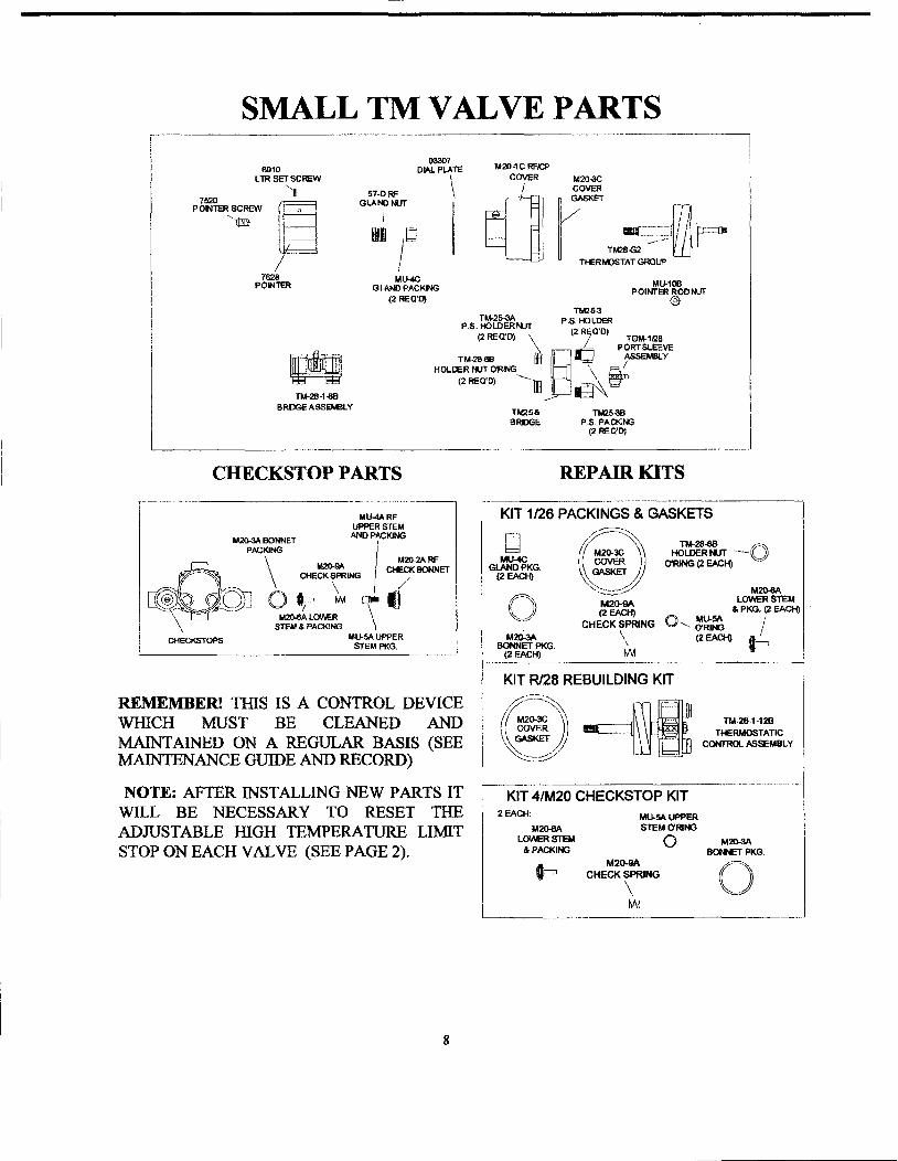
REMEMBER! TIllS IS A CONTROL DEVICE WIDCH MUST BE CLEANED ANDMAINTAINED ON A REGULAR BASIS (SEE MAINTENANCE GUIDE AND RECORD)
NOTE: AFTER INSTALLING NEW PARTS IT WILL BE NECESSARY TO RESET THEADJUSTABLE IllGH TEMPERATURE LIMIT STOP ON EACH VALVE (SEE PAGE 2).
7
MU-1OBPOINTER ROONVT
@
~r
.L~.-::::' II---..--TM28-G2
TIER KlSTAT GROUP
M2O-1 C RFICPCOVER
q]03301
OIf\l.PLATE
\I
MlJ..4CGlAND PACKtlG
(2 REQ'Oj
51-0RFGLANJ I'AJT
IIIfW bd
I
SMALL TM VALVE PARTS...------------------1I
6910LTR SET SCREW
'11520 fHPONlER SCREW I r "
"11mJ I ~I j-----j
J~---.J1628
POlNlER
TM-25-3AP.S_ HOLDERr-uT
TM-2S-HlBBRDGE ASSEYlLY
TM25-3P.S. HOLDER
(2 RiO'O)(2 REQ'O) \ . TGM-1I2S
m§1f=1. p~~~TM-28-6B til ""T' IHOLl:ER M..IT ORING ! \ ~.=1)
(2 REO'Oj '--lE'_I g\-TM25-6 TM25-3BBRDGE p.s PACKJNG
(2 REO'D)
CHECKSTOPPARTS REPAIR KITS
..- .... -----------...-------------------i
M2O-8ALOWER STEM
& PKG. (2 EACH)
0 .......= I(2EACH) ~
M2O-QA(2 EACH)
CHECK SPRING
\W
KIT 1/26 PACKINGS & GASKETS
((ii) =~-O~':::::::::~~/
bdMlJ-¢
GLANDPKG.(2 EACH)
_ _-----~
MU-4ARFUPPER STal
M2G-3A BONNET AND P~KlNG
PACKING I\ M2O-9A M20-2A RF
.•--"~ \ CHECK SPRING I CHECK BONNET
~-;:~- .~ \ ll/ !dl ))J' 0 tee, w QIIo i~S<- -~ LQ\o\ER \ .
STEM & PACKINGMlJ-5A UPPER
STEM PKG.
c@\
\CHECKSTOPS
KIT R/28 REBUILDING KIT
KIT 4/M20 CHECKSTOP KIT
REMEMBER! THIS IS A CONTROL DEVICEWHICH MUST BE CLEANED ANDMAINTAINED ON A REGULAR BASIS (SEEMAINTENANCE GUIDE AND RECORD)
NOTE: AFTER INSTALLING NEW PARTS ITWILL BE NECESSARY TO RESET THEADJUSTABLE mGH TEMPERATURE LIMITSTOP ON EACH VALVE (SEE PAGE 2).
2 EACH:
~I LO:T811
& PACKING
t=
MU-5AUPPERSTEM O'RlNG
oM20-QA
CHECK SPRING
\.11M
TM-28-1-12B
THERMOSTATICCONTROL ASSEMBLY
M2O-3ABONolET PKG.
()
8
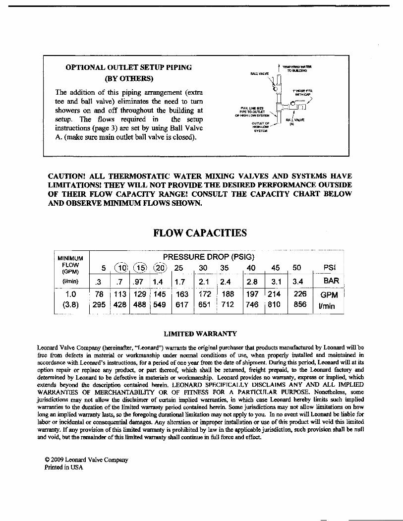
OPTIONAL OUTLET SETUP PIPING
(BY OTHERS)
The addition of this piping arrangement (extratee and ball valve) eliminates the need to turnshowers on and off throughout the building atsetup. The flows required in the setupinstructions (page 3) are set by using Ball ValveA. (make sure main outlet ball valve is closed).
I TEMPERED WATERI TOlIUUJNG
~-1R ,._~
~WrTHCAP
]:::1[djj=[J )RJl.l UNE SlZE ...
PIPE TO 0U11.£TOF ...GHLOWSYSTEM ,
rwl. VALVE~~~---'- CAl
SYSlEM
CAUTIONI ALL THERMOSTATIC WATER MIXING VALVES AND SYSTEMS HAVELIMITATIONS! THEY WILL NOT PROVIDE THE DESIRED PERFORMANCE OUTSIDEOF THEIR FLOW CAPACITY RANGEl CONSULT THE CAPACITY CHART BELOWAND OBSERVE MINIMUM FLOWS SHOWN.
FLOW CAPACITIES....
MINIMUM PRESSURE DROP (PSIG)FLOW 5 (1m C~§) I (~~ID 25 30 35 40 45 50 PSI(GPM) ........_-.-/ _ ••___0_' •.• -,.....-
(11m in) .3 .7 .97 11.4 1.7 2.1 2.4 2.8 3.1 3.4 BAR···i-·············· .......
1.0 78 113 129 1145 163 172 188 197 214 226 GPM(3.8) 295 42~ .._~~~j 549 617 651 712 746 810 856 IIminI
L ........... ..
LIMITED WARRANTY
Leonard Valve Company (hereinafter, "Leonard") warrants the original purchaser that products manufactured by Leonard willbefree from defects in material or workmanship under normal conditions of use, when properly installed and maintained inaccordance with Leonard's instructions, for a period of one year from the date of shipment. During this period, Leonard will at itsoption repair or replace any product, or part thereof, which shall be returned, freight prepaid, to the Leonard factory anddetermined by Leonard to be defective in materials or workmanship. Leonard provides no watTlUlty, express or implied, whichextends beyond the description contained herein. LEONARD SPECIFICALLY DISCLAIMS ANY AND ALL IMPLIEDWARRANTIES OF MERCHANTABILllY OR OF FITNESS FOR A PARTICULAR PURPOSE. Nonetheless, somejurisdictions may not allow the disclaimer of certain implied warranties, in which case Leonard hereby limits such impliedwarranties to the duration of the limited warranty period contained herein. Some jurisdictions may not allow limitations on howlong an implied warranty lasts, so the foregoing durationallimitation may not apply to you. In no event will Leonard be liable forlabor or incidental or consequential damages. Any alteration or improper installation or use of this product will void this limitedwarranty. If any provision of this limited warranty is prohibited by law in the applicable jurisdiction, such provision shall be nulland void, but the remainder ofthis limited warranty shall continue in full force and effect.
© 2009 Leonard Valve CompanyPrinted in USA

RP50366Stems (2) and Nuts (2)
Ensamble de laUnidad delVastago (2) y Tuerca (2)
Obturateurs (2)at Ecrou (2)
R~Test CapsTapa de PruebaCapuchon d'essai
RP46075P/aStarguardProtector de yesoProtecteur
,•• Ifl~I.(:
Asiento y Resorte Screen
SIegeet~r~rt ~:~sde malla
~I RP22734 RP46078I Bonnet Test Cap
Capuch6n Tapa de PruebaChapeau Capuchon d'essai
RP39404--------,PlasterguardfThin WallMounting BracketProtector de EnlucidolParedDelgada Soporte de MonturaBase du protecteurlSupportde Montage sur Pami Mince
RP46076----~~?~
CoverCublertaCouvercle
Models/Mode/os/Modeles R18224 Series/Series/Serio
RP25513----------------------.........Stem AssemblyEnsamble de la Unldad del VastagoObturateurs
MultiChoice® Universal Jetted Shower™ Rough-in BodyCorps Universel Brut MultiChoice® Jetted Shower™Tuberfa Interna Universal MultiChoice* Jetted Shower'"
RP61007BonnetCapuch6nChapeau
RP34787-:::=- _Stem Extender 6VJExtensi6n para Unidad del VastagoRallonge de Uge
RP37890 ~Retention ScrewTornillos de Retenci6nVis de Retenue
ASpeCify fini,h / Espedffque e/ AcabadD/Precisez /e fini
5\-\\5075LRev C 6-23-10
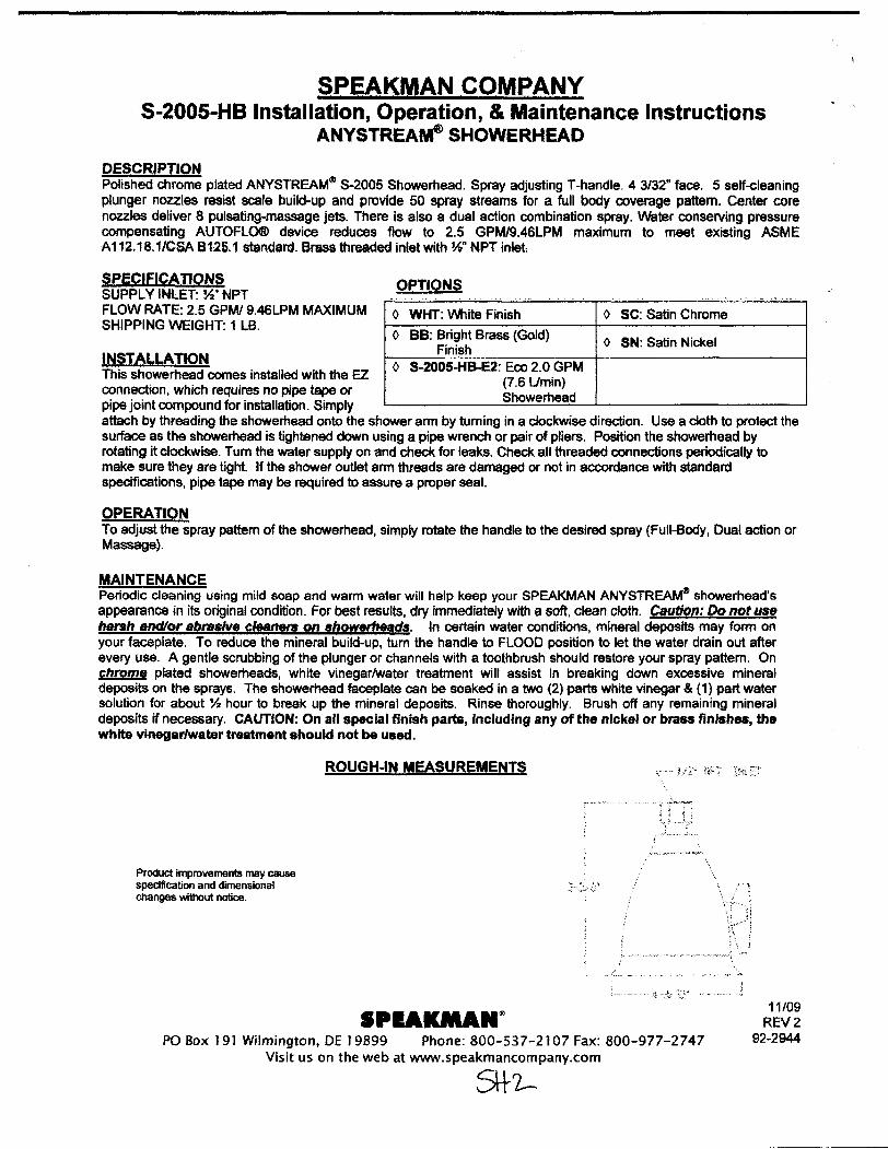
SPEAKMAN COMPANYS-2005-HB Installation, Operation, & Maintenance Instructions
ANYSTREA~SHOWERHEAD
DESCRIPTIONPolished chrome plated ANYSTREAM4Il 5-2005 Showerhead. Spray adjusting T-handle. 43/32" face. 5 self-cleaningplunger nozzles resist scale build-up and provide 50 spray streams for a full body coverage pattern. Center corenozzles deliver 8 pulsating-massage jets. There is also a dual action combination spray. Water conserving pressurecompensating AUTOFLO® device reduces flow to 2.5 GPMI9.46LPM maximum to meet existing ASMEA112.18.1/CSA B125.1 standard. Brass threaded inlet with W NPT inlet
OPTIONS-. - - .
0 WHT: VVhite Finish 0 SC: Satin Chrome
0 BB: Bright Brass (Gold) () SN: Satin NickelFinish
() S-2005-HB-E2: Eco 2.0 GPM(7.6 Umin)Showerhead
SPECIFICATIONSSUPPLY INLET: ~" NPTFLOW RATE: 2.5 GPMl9.46LPM MAXIMUMSHIPPING WEIGHT: 1 LB.
INSTALLATIONThis showerhead comes installed with the EZconnection, which requires no pipe tape orpipe joint compound for installation. Simplyattach by threading the showerhead onto the shower ann by turning in a clockwise direction. Use a cloth to protect thesurface as the showerhead is tightened down using a pipe wrench or pair of pliers. Position the showerhead byrotating it clockwise. Tum the water supply on and check for leaks. Check aU threaded connections periodically tomake sure they are tight. If the shower outlet ann threads are damaged or not in accordance with standardspecifications, pipe tape may be required to assure a proper seal.
OPERATIQNTo adjust the spray pattern of the showerhead, simply rotate the handle to the desired spray (Full-Body, Dual action orMassage).
MAINTENANCEPeriodic cleaning using mild soap and warm water will help keep your SPEAKMAN ANYSTREAMGIl showerhead'sappearance in its original condition. For best resUlts, dry immediately with a soft, clean cloth. cautio,,: Do not useharsh and/or abraslv. cleaners on sh0werheads. ~n certain water conditions, mineral deposits may form onyour faceplate. To reduce the mineral build-up, tum the handle to FLOOD position to let the water drain out afterevery use. A gentle scrubbing of the plunger or channels with a toothbrush should restore your spray pattern. Onchcpme plated showet1leads, white vinegarlwater treatment will assist in breaking down excessive mineraldeposits on the sprays. The showerhead faceplate can be soaked in a two (2) parts white vinegar & (1) part watersolution for about % hour to break up the mineral deposits. Rinse thoroughly. Brush off any remaining mineraldeposits if necessary. CAUTION: On all special finish parts, inclUding any of the nIckel or brass finIshes, thewhite vm.garlwater treatl1Htnt should not be used.
ROUGH-IN MEASUREMENTS
Product improvements may causespecification and dimensionalCllanges without notice.
.PIAKMAN~PO Box ]91 Wilmington, DE 19899 Phone: 800-537-2107 Fax: 800-977-2747
Visit us on the web at www.speakmancompany.com
5\+2-
11/09REV 2
92-2944

RP34794..EscutcheonChapel6nR06lIoo
RP17454.... (MetaVMetalicotMetal)Tub Spout/Pull-Down Diverter
TUbo de Salida para BalieralBol6n Desviador de Halar
Beclavec derivation derivation sur Embout
RP37891Jet SleeveManga del CharroManchon de Pulsation
)1Jr.-,,~n"~'l I
RP60254Shower RangePestana de la RegaderaCoIlerette
aO~
~RP37897"BonnetBoneteChapeau
:~~~~\
~RP46073Adapter AssemblyAdapladorAdaplaleur
RP23336(}flingAnUfo '0"Join! Torique
RP3210a..Handle AssemblyEnsamble de la ManijaPoignee
ShowerNffiBrazo de RegaderaTuyau de Pornme de Douche
RP34785 ------...Pivol Ring & SealAro Pivolado y EmpaqueAnneau de pivolemen! et joint
RP50880.. ----~Trim SleeveManga de FranjaManchon de Finllion
ShowerheadCabeza de RegaderaPomme de Douche
~r:~1~£\Llave Q)/
_ _______Cl8e~ ~:RP61918 ~Dlverte. Cartlidge (6 Function)Cartucho del desiador (6 funClones)Cartouche dlnvel'oou, (six foncllons)
::~ dTornillo de AjusleVis de Calage ():)
~~RP51920.ASleeve AssemblyEnsemble de la mangaManahan
RP3789Sa RP46463RP37896a Trim Ring Cartridge AssemblyHandle wlSet Screw Anillo de Franja Cartucl10Manlja con TornlOo de A1uste Anneau de Flnltion CartoucheManette avec Vis de Calage
RP28598 -------,.Decal (RedlBlue)Etiqueta (Rejo/Azul)Etiquette (RougelBlau)
RP28595aTemperature Knob and CoverPerilla de la Temperatura y CublertaPolgneil de Reglage de Temperature
~o·RP52387~ 6 Position l.abeI
EtiquelaS para las 6 posiciones~tiquette 6 positions
ModellMode/o/Mode/e T18230-XQ Series/Series/Serio
Innovations® Jetted Shower XO® TrimGarniture Jetted Shower XO® Innovations®Adorno Innovotionsepora Jetted Shower X08
._~ I~ ~
~\ ~ "..S0~i;:J == LlmllSlOP
Tope para UmltarBUlBe Rotative
..Specify finish / fS{)eCiflque el Acabedo I Pr8cisazle fin;
*NOTE: Do NOT overtighten SC'INI./ NOTA: NO aprie/e demas/ado e1 rom/llo';NOTE: NE serrez PAS crop la vis. TRIM ONLY

KOHLER.GENUINE PARTS
K·10597 K·10286
HandshowersDouchettes
Duchas de mane '
K-419
,,
/~n420
./~
n420
K·18495
I@
/n420
58461** 160' (152.4 em)] (K-9514)
34363~(;)
K·10343K-973
1050613-8- J
c~79003
"'Flnlsh/color code must be specified when ordering.""Yous devez apeclfler les codes de Ia Inltlon etlou de Ie couleur quend VOUB pa8aez votrtt commande.
**Se dabe especlflcar eI c6dlgo del acabadolcolor con .1 pediclo.
P.1/1 @ 2010 Kohler Co.

KOHLER.GENUINE PARTS
Wall-Mount Supply Elbow·Coude d1alimentatlon it montage mural
Codo de sumlnlstro de montaje a la pared ';
/'92402""
1QS5801-a-D
"Finish/color code must be specified when ordering."Yous deV4N: specifier lea CodllS de la f1nltlon et/ou de Is couleur qu.nd YOUS pa_ votre commande.
"Be debe lISpaciflcar .. c6dlgo del acabadolcolor con el pedldo.
P.111 C 2009 Kohler Co.
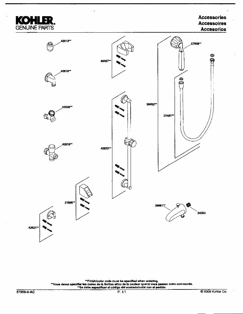
KOHLER.GENUINE PARTS
AccessoriesAccessoiresAccesorios .
21481**
42622"
"Flnlahlc:olor code must be apec:lfIed whan ordertng.""You. devez ap8c:lfler lea c:od.. de Ie flnlUon etlou dela c:ouleur quand voua pa&&8Z votre c:ommande.
""Sa debe especlftc:er 81 c6dlgo del acablldolcolor c:on .. pedldo.
87908-8-AC P.tl1 @ 2009 Kohler Co.

SLClAN. Repair Parts and Maintenance Guide
Regal~
Flushometer
11. 03021011 B-7-A CP Socket Assembly10. 0301082 A-6 CP Handle Coupling
12. 5302274 B-32 CP Handle GrIp -12 per package0302389 B-74-A CP Hand~ Handle Grip (ADA Compliant)
TllO repair k11s and pWllsted0I11hls PlI'IO are tl89Ilnod 10scM:e ai Sloan liaphragm typeA_melar., jnc\Jdjng Ii'osemanLllaotuled lor lowCMSurnp1iln ilGJ USlIQC.
A88R£'11AJ1011S:CP = Chrome pIaI8dmX = g~lons per flushl.p1 =Ut.... per "LOllLC~Low""""""lll
i>I<g ~ package
CP Handicap Handle Assembly(ADA Compliant)
CP Handle Assembly - 6 per packageDescription
B-32-APart No.
B-73-A03023909. 5302279
TAILPIECES, CONTROL STOPS AND fLUSH CONNECTIONSFor additional information on tailpieces, COI1trol stops and flushconnections see Section 4.
nemNo. Code No.
oS; "
PARTS UST
1. 0317004 R-1 0 CP Cover2. 0301168 A-71 Inside Cover
7. SEE INSIDE PARTS KITS CHART ON NEXT PAGE
SEE ITEMS 3A THROUGH BE IN CHART ON NEXT PAGE
14. 5301139 A-31 Handle Gasket-48 per package15. 0306102 F-54-A 3/4" CP Spud Coupling Assembly
0306142 F-55-A 1-1/4" CP Spud Coupling Assembly
t see palJ& 42.1 f" addlliooalletlQllls'FO! LOe v.ith 1" and 314" H-740-A CP (less cap).,,~ I" - H-540·A CP (v.ith H·37 cajlJ BaJ<.Cl'ek" scre'Mlriwrcontrol SlOPS
''f<Jr lise with 314" H-74O-A CP Bak-Ghel." scr,,,d_ cootrol~
25. 5310034 J·VJ·7 Bumper Assemllly - 6 per pack.age
0306145 F-56-A 1-1/2" CP Spud Coupling Assembly
24. 5308158 H-37 CP Gap - 6 per package
23. 0308991 H-639 CP Bonnet •
ll3086O1 H-538 CP Bonnet -
16. 3323192 V-551-A Vacuum Breaker Repair Kit
20A. 53Oll696 H-553 O-nng - 24 per package
22. 3308853 H-541-ASO 1" Control Stop Repair Ktt •3308856 H-543-ASO 3/4" Control Stop Repair Kit ••
13. 5302305 B-SO-A Handie Repair Kit - 6 per package
19. 0308801 H-551-A CP Adjustable Tailpiece 2-1116" long I
21 D388029 H-74o-A 1" Screwdriver Bak-Chek" Stop CP - colflllete0388031 H-74o-A 3/4" Screwdriver Bak·Chek" Slop CP - cornP*rte
18. 0308676 H-550 CP Stop Coupling I
20B. 5308381 H-552 LocI<Jng ling -12 per package
17. 5323005 V-500--AA 3/4" x 9" CP Vacuum Breaker - 6 per pw;kage5323006 V-500-AA 1-1/4" x9" CP Vacuum Breaker - 6 per package5323007 V-500-AA 1-1/2" x9" CPVacuum Breaker- 6 per pad<age
Guide Assembly 1.0 gpfl3.8 Lpf LC Urlnal12 per package
Guide Assembly 1.6 gpfl6.0 Lpf LC CIoset12 per package
Diaphragm - for all Inside Parts Kits 12 per package
Disc - for all Inside Parts Kits - 12 per package
GUide Assembly 3.5 gpfl13.2 Lpf Closet12 per package
Relief Valve, Blue (9 Uter CIoset)- 12 per package
5. 5301188 A-156-A4. 5301111 A-15-A
60. 5301155 A-155-A
6E. 5301157 A-157-A Guide Assembly 0.5 gpf/l.9 Lpf UrlnaI12 per package
8. 5302297 6-39 seal - 12 per package
3C. 5301211 A-19-ALC Relief Valve, Green (Close1IUrlnal-LC) 12 per package
6C. 5301031 A-151-A
6A. 5301236 A-l63-A Guide Assembly 4.5 gpf/17.0 Lpf Closet &15 gpf/5.7 Lpf Urlnal-12 per package
3D. 0301143 A-19-AL
6B. 5301032 A-152-A
3A. 5301058 A-19-AC Relief VaNe, WMe lOose!) - 12 per package3B. 5301059 A-l9-AlJ Relief Valve, Black (lJlinaQ -12 per package
118mNo. Code No. Part No, DescrIption
082009

,SLOAN. Repair Parts and Maintenance Guide
RegaleFlushometer
MASTER RUSHOMETER REBUILDING KITS(SEE PARTS UST - ON PREVIOUS PAGE)Refer to Parts List. Includes ~ems 7, 13, 16 &20Code No. Part No. Description3317001 R-1001 -A Rebuild Kit (4.5 gpf/17.0 Lpj) aosetlService Sink3311002 R-1002-A Rebuild Kit (1.5 gpf/5.7 Lp~ Urinal3317003 R-1003-A Rebuild Kit (3.5 gpf/13.2~ Ooset3317004 R-l004-A Rebuild KIt (1.6 gpf/6.0~ Closet3317005 R-l005-A Rebuild Kit (1.0 gpfl3,B Lp~ LC Urinal3317011 R-1011-A Rebuild KIt (0.5 gpf/1.9lp~ UrInal3317012 R-1012-A Rebuild Kit {2,4 gpfl9.0 Lp~ Closet
REPAIR KIT WASHER SET (SEE PARTS UST - ON PREVIOUS PAGE)5301189 A-l56-AA Repair Kit Washer Set -Includes; 4. 5, B& 14
ITEM 7. INSIDE PARTS KITS (SEE ILWSTRATIONS BELOW)
SPOO COUPlJNGSPUJ FUINGE
ItemNo.
B.C.D.
E.F.G.
CodlINo.3301036330103733010383301041330104433010813301024
Part No,A-36-AA-37-AA-38-AA-41-AA-42-A
A-43·AA-44-A
AppIlcatlon4.5 gpf117.0 Lpf - Closet1.5 gpl/5.7 Lpf - Urinal3.5 gpf/13.2 Lpf - Closet1.6 gpf/6,0 Lpl - CIosel
1.0 gpf/3.B Lpl - Urtnal0.5 gpf/19 Lpf - Urinal2.4 gpll9.0 Lpl - CIoseI
ITEM 7. INSIDE PARTS COMPONENTS (SEE ILWSTRATIONS BELOW)IblmNo. Code No. Part No, D1I8CI1ptIonSA. 5301058 A-19-AC Relief ValVe, White (Closet) -12 per pkg.36. 5301059 A-l9-AU Relief Valve, Black (UrinaO -12 per pkg.3C. 5301211 A-19-ALC Relief Valve, Green (ClosetIUrtnal-LC) -12 per pkg.
3D. 0301143 A-19-AL Relief ValVe, Blue (9 Liter Closet) -12 per pkg.
4. 5301111 A-15-A Disc - for ail Inside Parts Kits - 12 per pkg.5. 5301188 A-156-A Diaphragm -lor all Inside Parts Kits - 12 per pkg.
6A. 5301236 A-163-A GUide Assembly 4.5 gpl/17.0 Lpl Closet &1.5 gpfl5,7 Lpl Urinal -12 per package
6B. 5301032 A-152-A Guide Assembly 3,5 gpf/13.2 Lpf Closet-12 per package
6C. 5301031 A·151-A Guide Assembly 1.6 gpf/6.0 Lpf LC Ooset-12 per package
60. 5301155 A-155-A Guide Assembly 1,0 gpf/3,BLpf LC Urinal -12 per package
6E, 5301157 A-157-A Guide Assembly 0,5 gpfl19 Lpl urinal -12 per package
4.5 gpf/17.0 Lpf 1.5 gpfl5.7lpf 3.5 gpf/13.2 Lpf 1.6 gpfl6.o lpf 1.0 IJIlfI3.8 Lpf 0,5 gpffl.9lpf 2.4 gpfl9.0 lpf
032008
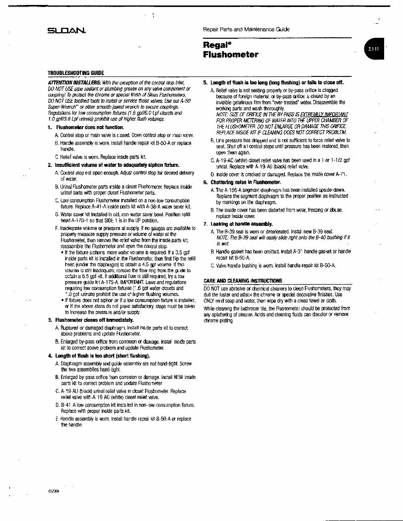
SLOAN.
TROUBlESHOOTING GUIDE
ATTENTION INSTALLERS: With the exceptiofl of the control stop inlet,DO NOT USEpipe sealant or plumbing grease on any valve component orcoupling! To protect the chrome or special finish of Sloan Flushameters,DO NOT USE toothed tools to Install or service these valves. Use ourA-SOSUper-Wrench"' or ather smooth-jawed wrench to secure couplings.Regulations for low consumption fixtures (1.6 gpf/6.0 Lpf closets and1.0 gpf/3.B Lpfurinals) prohibit use of higher flush volumes.
1. Flushometer does not function.
A. Control stop or main valve is closed. Open control stop or main valve.B. Handle assembly is worn. Install handle repair kit B-50-A or replace
handle.
C. Relief valve is worn. Replace inside parts k~.
2. Insufficient volume of water to adequately siphon fixtUre.A. Control stop not open enough. Adjust control stop for desired delivery
of water.
B. Urinal Flushometer parts inside a closet Rushometer. Replace insideurinal parts with proper closet Flushometer parts.
C. Low consumption Flushometer installed on a non-low consumptionfixture. Replace A-41-A inside parts kit with A-3B-A water saver kit.
O. Water saver kit installed in old, non-water saver bowl. Position refillhead A-170-1 so that SIDE 1 is in the UP posltkm.
E. Inadequate volume or pressure at supply, If no gauges are available toproperly measure supply pressure or voIume of water at theFlushometer, then remove the relief valve from the inside parts kit,reassemble the Rushometer and open the control stop.• If the fixture siphons, more water volume is required. If a 3.5 gpf
inside parts kit is installed in the Flushometer, then first flip the refillhead (under the diaphragm) to obtain a 4.5 gpf volume. If thisvolume is still inadequate, remove the flow ring from the guide toobtain a 6.5 gpf kit. If additional flow is still required, try a lowpressure guide kit A-175-A. IMPORTANT: Laws and regulationsrequiring low consumption fixtures (1.6 gpf water closets and1.0 gpf urinals) prohiM the use of higher flUshing volumes.
• If fixture does not siphon or if a low consumptkm fiXture is installed,or if the above steps do not prove satisfactory, steps must be takento increase the pressure and/or supply.
3. Flushometer closes off immediately.A. Ruptured or damaged diaphragm. Install inside parts kit to correct
above problems and update Flushometer.
B. Enlarged by-pass orifice from corrosion or damage. Install inside partskit to correct above problem and update Flushometer.
4. Length of flush Is too short (short flUshing).A. Diaphragm assembly and guide assembly are not hand-tight. SCrew
the two assemblies hand-tight.
B. Eniarged by-pass orifice from corrosion or damage. Install NEW insideparts kit to correct problem and update Rushometer.
C. A-1 9-AU (black) urinal relief valve in closet Flushometer. Replacerelief valve with A-1 9-AC (white) closet relief valve.
D. B-41-A low consumption kit installed in non-low consumption fixture.Replace with proper inside parts kit.
E. Handle assembly is worn. Install handle repair kit B-SO-A or replacethe handle.
032008
Repair Parts and Maintenance Guide
RegaleFlushometer
5. Length of flush is too long (long flushing) or falls to close off,
A. Relief valve Is not seating properly or by-pass orifice is cloggedbecause of foreign material, or by-pass orifice is closed by aninvisible gelatinous film from 'over-treated" water. Disassemble theworking parts and wash thoroughly.NOTE: SJZE OF OR/ACE IN THE BY-PASS IS EXTREMELY IMPORTANTFOR PROPER METERING OF WATER INTO THE UPPER CHAMBER OFTHE FLUSHOMETER. DO NOT ENlARGE OR DAMAGE THIS OR/RCE.REPLACE INSIDE KIT IF CLEANING DOES NOT CORRECT PROBLEM.
B. Une pressure has dropped and is not sufficient to force relief valve toseat. Shut off all control stops until pressure has been restored, thenopen them again.
C. A-19-AC (white) closet relief valve has been used in a 1 or 1-112 gpfurinal. Replace with A-19-AU (black) relief valve.
D. Inside cover is cracked or damaged. Replace the inside cover A-71.
6. Chattering noise In FIushometer.A. The A-156-A segment diaphragm has been installed upside-down.
Replace the segment diaphragm to the proper position as instructedby markings on the diaphragm.
B. The inside cover has been distorted from wear, freezing or abuse.replace inside cover.
7. leaking at handle assembly.
A. The B-39 seal is worn or deteriorated. Install new B-39 seal.NOTE: The B-39 seal will easIly slide right onto the 8-40 bushing if itIs wet.
B. Handle gasket has been omitted. Install A-31 handle gasket or handlerepair kit B-50-A.
C. Valve handle bushing is worn. Install handle repair kit B·5o-A.
CARE AND ClEANING INSTRUCTIONSDO NOT use abrasive or chemical clearers to clean Flushometers, they maydull the luster and attack the chrome or special decorative finishes. UseONLY mild soap and water, then wipe dry with aclean towel or cloth,While cleaning the bathroom tile, the Rushometer should be protected fromany splattering of cleaner. Acids and cleaning fluids can discolor or removechrome plating

KOHLGENUJNE PARTS
Two-Piece Toiletsw.e. deux pieces
InodorDS .de .des plezas·
10332'
~'057940 r'
~83143
~85307
1069722For Plastic Trip AnnPour bras de dEiclenchement en p1astiquePam brazo de descarga de p1astico1088115For Metal Trip ArmPour bras de dooenchernent en metalPara brazo de descarga de metal
tJ",,-51676
~84591·T**
51570",,-
51572""- 0
(,/
--51571** ..-51540** ""-'if"
51537 ""-l'f""-rr
Tank Lock OptIon (one side shown)Option verrou du reservoir (un cOte illustre)Opci6n de seguros para la tapa del tanque (se ilustra un lado)
~84591" ~
./':1070291 I
131059291~
1016219A
...........78132
1069723** (LH Plastic ArmBras p1astique gaucheBrazo de pl8stico izquierdo)(Use wllhlUtlliser aveclU1llice con)1069722
1079806** (RH Metal ArmBras metal droitBrazo de metal der)(Use wlthlUtillser aveclUtillce con)1088115
1069724" (LH Metal AnnBras metal gaucheBrazo de metallzq)(Use withlUtiliser aveclUtilice con)1086115
1083167/~
1014066
1013092" rO'(2 ea./2 ch.l2 clu) tr//~
....
*"FInish/color code must be specified when ordering."Vou. devez specifier les codes de 18 tlnltion at/au de 18 couleur quand YOU. passez votrs commande,
**Se debe especlflcar eI cOdlgo del acabadolcolor can eI pedldo.
P.1/1 C 2009 Kohler Co.
I~I( -\

KOHI.Eft.GENUINE PARTS
Two-Piece Toiletsw.e. deux pieces
Inodoros de dos piezas',
t:J",51676
~84591·T"
51570",51572 4)
"""-..r
/)51571Z. ,/
51540*""",,- !lY"
51537 r'"""-~
Tank Lock Option (one side shown)Option verrou du reservoir (un cole illuslrl3)Opcl6n de segums para Ie tapa del tanque (sa i1ustra un lado)
1069722For Plastic Trip AnnPour bras de d9clenchement en p1astlquePara brazo de descarga de p1asllco1086115For Metal Trip ArmPour bras de dEiclencilement en metalPara brazo de descarga de metal
t~
1070291 Itj~
1059291 0A
1016219
/4>1014065
/~1014580
/@1018165-A
~84591*"(t"""
78132
1083167
1069723*" (LH Plastic ArmBras p1astique gaucheBrazo de p1astlco izquierdo)(Use withIUtIllser avecAJlilice COIl)1069722
1079806** (AH Metal ArmBras metal droitBrazo de metal der)(Use witMJtlHser avecAJlilice con)1086115
1069724" (LH Metal ArmBras metal gaucheBrazo de m&tal Izq)(Use wlthlUtiliser aveclUtltlce con)1086115
1013092"* rO'(2 ea./2 chJ2 cJu) ~> __ /1
....
'*Flnlahlcolor code must be epeclfled when ordering."Voue devez ep8clfler lee codee de Ie flnttlon et/ou de la couleur quand voua pa_ votre commande.
**se debe eepeciflcar 81 c6dlgo del acabedoicolOl' con 81 padldo.1074736-8-0 . P.1/1
\~1>7~C 2009 Kohler Co,

KOHLlft.GENUJNEPARTS
Two-Piece Toiletsw.e. deux pieces .
lnodor.os de dos piezas .
1033209"-.
~'0579<0 r~ 83143
1/85307•
1.1"-.51676
51570"-.
51572"-. 4\
(',
,',)51571- /
51540- "-.W'."-.
51537'-....rr ~
Tank Lock Option (one side shown)Option verrou du n:iseIVoir (un cote iIIustre)Opci6n de seguros para la tapa del tanque (sa i1ustra un lado)
1069722For Plastic Trip AnnPour bras de d8clenchement en plastiquePara brazo de descarga de p18st1co1086115For Metal Trip AnnPour bras de d9clenchement en metalPara brazo de descarga de metal
~84591-
1069723"* {lH Plastic ArmBras p1astique gaucheBrazo de plastico Izquierdo}(Use withlUtilisar aveclUtillce con)1069722
1079808"* (RH Metal ArmBras metal droitBrazo de metal der)(Use wlthlUtlliser aveclUtilice con)1086115
1069724"* (LH Metal AnnBras metal gaUcheBrazo de metal izq)(Use wlthA.J1ilisar aveclUtllice con)1086115
1083167
-"-.0"-.1057941
8 42398"-.
42397
1013092"* rb'(2 eaJ2 chJ2 cIu)~ ••/'1
...
*"fInish/color code must be specified when ordering.**Yous devez speclfler lea codes de Is finltlon etIou de Ia couleur quand vous paseez votre commande.
**Se debe eapeclflcar eI c6dlgo del 8cabadofcolor con el pedldo.1074736-8-0 P.1/1 C 2009 Kohler Co.

SLOAN. Repair Parts and Maintenance Guide
RegaleFlushometer fI
11. 0302109 B-7-A CP Socket Assembly10. 0301082 A-6 CP Handle CoUpling
12. 5302214 8-32 CP Handle GrIp-12 per package0302389 B-74-A CP Handicap Handle Gnp (ADA Compllanij
T!lor'flllirldlsllllllpartsTISIed(lfl \I'lS page are desI1lrrJd toser'lice II SkJM diap/l'"llJTl1\llCflLls_.... ir<ItJdlnIllhooemaroJfacturedfol kwlCClflS\IIIIlIia I-Cl usage.
~
CP =CIrcmc Iliate<lgpf = gallons per """lp/=Li1e'$per1lushLC =Low comumplionpI'lJ = pacI<age
CP Handle Assembly - 6 per pacl<ageCP Handicap Handle Assembly(ADA Compliant)
DescriptionPart No.B-32-AB-73-A0302390
9. 5302279
TAILPIECES, CONTROL STOPS AND FLUSH CONNECTIONSFor additional information on tailpieces, control stops and flushconnections see Section 4.
ItemNo, Code No.
PARTS UST
7. SEE INSIDE PARTS KITS CHART ON NEXT PAGE
1. 0317004 R-10 CP Cover2, 0301168 A-71 Inside Cover
8. 5302297 B-39 Seal - 12 per package
14. 5301139 A-31 Handle Gasket - 48 per package15. 0306102 F-54-A 3/4" CP Spud Coupling Assembly
0306142 F-55-A 1-1/4" CP Spud CoupiingAssembt)'
23. 0308991 H-{)39 CP Bonnet'0308601 H-538 CP Bonnet ~
25. 5310034 J-2JJ-7 Bumper Assembly - 6 per package
17. 5323005 V-500-AA 3/4" x9" CP Vacuum BrOOker - 6 per package5323006 V-500-AA 1-1/4" x9" CP Vacuum Breaker - 6 per package5323001 V-500-AA 1-1/2" x 9" CP Vacuum Breaker - 6 per package
0306145 F-5B-A 1-112" CP SpUd CouplfngAsse~
24. 5308156 H-37 CP Cap - 6 per package
208. 5308381 H-552 Locking ring -12 per package
16. 3323192 V-551-A Vacuum Breaker Repair Kit
19. 0308801 H-551-A CP Adjustable Tailpiece 2-1116" long'
13. 53023lIi B-50-A Handle Repair Kit - Bper package
1B. 0308676 H-550 CP Stop CoUpling I
22. 3308853 H-541-ASD 1" CorttroI Stop Repair KIt·3308856 H-543-ASD 3/4" Control Stop Repair KIt ~
21. 0388029 H-740-A 1" Screwdnver Bak.-GheK" Stop CP - complete0388031 1i-740-A 3/4" SCrewdriver Bak-Ghek" Stop CP - complete
20A 53OlIll98 1i-553 O-nng - 24 per package
t see page 4.2.1 lor ad_lengllls"for use wit" I" aM lI4' H-74O-A C? (less capl BI1d " - H-54O-A CP (>MI!l H·37 cap) BaI<-C/lek" SCteWIlrM!rcontlTllslops
"For use wiItl3l4' H·740·A CP Bak-Chek" scmwrf!1ver conlrnl8fOP$
Guide Assembly 0.5 gpt/1.9 Lpf Urinal12 per package
Guide Assembly 1.0 gpf/3.8 Lpl LC Urinal12 per package
Disc - lor all Inside Par1s Kits - 12 per packageDiaphragm - for all Inside Parts Kits 12 per package
Guide Assembly 1,6 gpll6.0 Lpf LC Closet 12 per package
Relief Valve, Blue (9 Liter Closet) - 12 per package
5. 5301188 A-156-A4. 5301111 A-15-A
6E. 5301151 A-157-A
6A. 5301236 A-163-A GUide Assembly 4.5 gpt/17.0 Lptaoset &1.5 gptl5.7 Lpf ltlnal-12 per pacl<age
60. 5301155 A-155-A
6C. 5301031 A-151-A
30 0301143 A-19-AL
6B. 5301032 A-152-A Guide Assembly 3.5 gpt/13.2 Lpl Closet12 per package
3C 5301211 A-19-ALG Relief Valve, Green (CiosetlUnnal-lC) 12 per pacl<age
3A. 5301058 A-19-AC Relief Valve, WIIite (CIoaeij - 12 per package38. 5301059 A-19-AU Relief Valve, Black (Urinal) - 12 per package
ItllmNo. Code No. Part No. DescrIption
sa: ITEMS 3A THROUGH BE IN CHART ON NEXT PAGE
062009

-------------------------------
SLCJAN~
COI'ffi
FlUSH CONNEC1lONiVAClDol BRfAKER)
Repair Parts and Maintenance Guide
RegaleFlushometer
MASTER R.USHOMETER REBUILDING KITS(SEE PARTS UST - ON PREVIOUS PAGE)Refer to Parts Us!:. Includes ~ems 7, 13, 16 & 20Code No. Part No. Description3317001 R-1001-A Rebuild Klt (4.5 gpf/17.0 l.jJO CIosetISeMce SIllk3317002 R-1D02-A Rebuild Kit (1.5 gpf/5.7Lpf) Urinal3317003 R-l D03-A Rebuild Kit (3.5 gpfl13.2 Lpn Closet3317004 R-l DOH Rebuild KIt (1 ,6 gpfl6.0 Lpl) Closet3317005 R-l005-A Rebuild K~ (1 ,0 gpl/3.8 Lpn LC Urinal3317011 R-l011-A Rebuild KIt (0,5 gpfl1.9 Lpf) Urinal3317012 R-l012-A Rebuild KJt (2.4 gpl/9.0 Lpn Closet
REPAIR KIT WASHER SET (SEE PARTS UST - ON PREVIOUS PAGE)5301189 A-l56-AA Repair Kit Washer Set -lrJcludes: 4, 5,8 & 14
ITEM 7. INSIDE PARTS KITS (SEE ILLUSTRATIONS BELOW)
SPlll COlJ'UHlJ
ItemNo.A.B.C.D.E.F.G.
Code No.3301036330103733010363301041330104433010813301024
Part No.A-36-AA·37-AA-38-AA-41-AA-42-AA-43-AA-44-A
Application4,5 gpf/17.0 Lpf - Closet1,5 gpf/5.7 Lpf - lkina!3,5 gpf113.2 Lpf - Closet1.6 gpf/6.0 Lpf - Closet1.0 gpfl3.8 Lpf - Urinal0.5 gpfl1.9Lpf - Urlnal2.4 gpl/9,0 Lpf - Closet
ITEM 7. INSIDE PARTS COMPONENTS (SEE ILLUSTRATIONS BELOW)ItemNo. COde No. Part No. Descrlptlon3A. 5301058 A-19-AC Relief Valve, While (Closet) - 12 per pkg.3B. 5301059 A-l9-AU Reliel Valve, Black (Urinal) -12 per pkg.3C, 5301211 A-19·ALC Relief Valve, Green (CloseVUrinal-LC) -12 per pkg.30. 0301143 A-19-AL Relief Valve, Blue (9 L~r Closet) - 12 per pkg.
4. 5301111 A-l5-A Disc - for aJllnslQe Parts Klts - 12 per pkg,5 5301188 A-l56-A Diaphragm - lor all Inside Parts KIts -12 per pkg.
6A. 5301236 A-l63-A Guide Assembly 4.5 gpf/17.0 Lpf Closet &1.5 gpf/5.7 Lpf UrlnaJ -12 per package
6B. 5301032 A-152-A Guide Assembly 3.5 gpl/13.2 Lpf CIoset-12 per package
6C 5301031 A-151-A Guide Assembly 1.6 gpf/6.0 l.pf LC Closet-12 per package
60. 5301155 A-155-A Guide Assembly 1,0 gpfl3.8 Lpf LC lJrlnal-12 per paCkage
6E. 5301157 A-157-A Guide Assembly 0,5 gpfJl.9 Lpf Urlnal-12 per package
4.5 gpf/17.0 Lpf 1.5 gpfl5.7 Lpf 3.5 gpt/13.2 Lpf 1.6 gpfl6.o Lpf 1.0 gpt/3.S Lpf 0.5 gpfl1.9 Lpf 2.4 gpfl9.0 Lpf
032008

SLOAN.
TRDUBlESHOOnNG GUIDE
AITENTION INSTALLERS: With the exception of the control stop inlet,DO NOT USE pipe sealant or plumbing grease on any vaIvB component orcoU{J1ing! To protect the chrome or s{Jf!Cial finish ofSloan Aushometers,DO NOT USE toothed tools to install or service these valves. Use ourA-50Super-WrencW or other smooth-jawed wrench to secure couplings.Regulations for low consumption fixtures (1.6 gpf/6.0 Lpfclosets and1.0 gpf/3.8 Lpf urInals) prohibit use of higher flush volumes.
1. Flushometer does not function.A. Control stop or main valve is closed. Open control stop or main valve.S. Handle assembly is worn. Iflstall handle repair kit B-50-A or replace
handle.
C. Relief valve is worn. Replace inside parts kit.
2. Insufficient volume of water 10 adequately siphon fixture.A. Control stop not open enough. Adjust control stop for desired delivery
of water.B. Urinal Flushometer parts inside acloset RUshometer. Replace inside
urinal parts with proper closet Rushometer parts.
C. Low cOflsumption Flushometer installed on a non-low consumptionfixture. Replace A-41-~ inside parts kit wlth A-38-A water saver kit.
D. Water saver kit installed in old, non-water saver bowl. Position refillhead A-170-1 so that SlOE 1 is in the UP position.
E. Inadequate volume or pressure at supply. If no gauges are available toproperly measure supply pressure or volume of water at theRushometer, then remove the relief valve from the inside parts kit,reassemble the Rushometer and open the control stop.• If the fixture siphons, more water volume is required. If a 3.5 gpf
inside parts kit Is installed in the Flushometer, then fjrst flip the refillhead (under the diaphragm) to obtain a 4.5 gpf volume. If thisvolume is stili inadequate. remove the flow ring from the guide toobtain a 6.5 gpf kit. If additional flow is still required. try a lowpressure gUide kit A-175-A. IMPORTANT: Laws and regulationsrequiring low consumption fixtures (1.6 gpf water closets afld1.0 gpf urinals) prohibit the use of higher flushing volumes.
• If fixture does not siphon or if a low consumption fIXture is installed.or if the above steps do not prove satisfactory, steps must be taJ<ento increase the pressure and/or supply.
3. Flushometer closes off Immediately.A. Ruptured or damaged diaphragm. Install iflside parts kit to correct
above problems and update Flushometer.
B. Enlarged by-pass orifice from corrosion or damage. Install inside partskit to correct above problem and update Flushometer.
4. length of flush is too short (short flUshing).A. Diaphragm assembly and guide assembly are not hand-tight. Screw
the two assemblies hand-tight.
B. Enlarged by-pass orifice from corrosion or damage. Install NEW insideparts kit to correct problem and update Flushometer.
C. A-19-AU (black) urinal relief valve ifl closet Flushometer. Replacerelief valve with A-19-AC (white) closet relief valve.
D. B-41-A low consumption kit installed ifl flon-Iow consumption fixture.Replace with proper iflside parts kit.
E. Handle assembly is worn. Install handle repair kit B-50-A or replacethe handle.
032008
Repair Parts and Maintenance Guide
RegaleFlushometer
5. length of flush Is too long (long flushing) or falls to close off.A. Relief valve is not seating properly or by-pass orifice is clogged
because of foreign material, or by-pass orifice is closed by aninvisible gelatinous film from "over-treated' water. Disassemble theworking parts and wash thoroughly.NOTE' SIZE OF ORIACE IN THE BY-PASS IS EXTREMELY IMpoRTANTFOR PROPER METERING OF WATER INTO THE UPPER CHAMBER OFTHE FLUSHOMETER. DO NOT ENLARGE OR DAM4GE THIS ORIFICE.REPLACE INSIDE KJT IF C/.£ANING DOES NOT CORRECT PROBLEM.
B. Line pressure has dropped and is not sufficieflt to force relief valve toseat. Shut off all cofllrol stops until pressure has been restored, thenopen them again.
C. A-19-AC (white) closet relief valve has been used in a 1 or 1-1/2 gpfurinal. Replace with A-19-AU (black) relief valve.
D. Inside cover is cracked or damaged. Replace the inside cover A-71.6. Chatt8ring noise In F1ushometer.
A. The A-156-A segment diaphragm has been installed upslde-down.Replace the segment diaphragm to the proper position as Instructedby mar1<ings on the diaphragm.
B. The inside cover has been distorted from wear, freezing or abuse.replace inside cover.
7. Leaking at handle assembly.A. The B-39 seal is worn or deteriorated. Install new 8-39 seal.
NOTE: The B-39 seal will easily slide right onto the 8-40 bushing if itis wet.
8. Handle gasket has been omitted. Install A-31 handle gasket or handlerepair kit B-50-A.
C. Valve handle bushing is worn. Install handle repair kit B-50-A
CARE AND ClEANING INSmUCTlONSDO NOT use abrasive or chemical cleaners to clean Rushorneters. they maydull the luster and attack the chrome or special decorative finishes. UseONLY mild soap and water, then wipe dry with a clean towel or cloth.While cleaning the bathroom tile, the Flushometer should be pro1ected fromany splattering of cleaner. Acids and cleaning fluids can discolor or removechrome plating.

ERFP8C"C ERFPVR8C"A LNFE8C"C
Installation/Care/Use ManualSoft Sides® Refrigerated Fountains with FLEXI-GUARO@
C?J----~._-- ..,---
- -~;: ~
--i---- -- -
ERFP8CInstaller
To assure you install this model easily and correctly, PLEASE READTHESE SIMPLE INSTRUCTIONS BEFORE STARTING THE INSTALLATION. CHECK YOUR INSTALLATION FOR COMPLIANCE WITHPLUMBING, ELECTRICAL AND OTHER APPLICABLE CODES. Afterinstallation, leave these instructions inside the fountain for future reference.
IMPORTANTALL SERVICE TO BE PERFORMED BY AN AUTHORIZED SERVICE PERSON
IMPORTANT! INSTALLER PLEASE NOTE.THE GROUNDING OF ELECTRICAL EQUIPMENT SUCH AS TELEPHONE, COMPUTERS, ETC. TO WATER LINESISACOMMON PROCEDURE THIS GROUNDING MAY BE IN THE BUILDING OR MAY OCCURAWAY FROM THEBUILDING. THIS GROUNDING CAN CAUSE ELECTRICAL FEEDBACK INTO A FOUNTAIN, CREATING AN ElECTROLYSIS WHICH CAUSES A METAlLIC TASTE OR AN INCREASE IN THE METALCONTENT OF THE WATER.THIS CONDITION ISAVOIDABLE BY USING THE PROPER MATERIAlSAS INDICATED.ANY DRAIN FITTINGSPROVIDED BY THE INSTALLER SHOULD BE MADE OF PLASTIC TO ELECTRICAlLY ISOLATE THE FOUNTAINFROM THE BUILDING PLUMBING SYSTEM.
ilI8" 0.0. UNI'LAT£O114" 0.0. TUBE COPPER TUBE COIllNECT BUILDING WATER
~~~~a:T COLDWAT£RSUPPlY INLET
c:=::'=::::::l'\ ~=ry=bPUSHING fUll( IN BEFOREPULLING II OUT HELPS Ia
RELEASE TUBE
TUBE IS SECURCO PUSH IN COLLETIN POSITION TO RELCASE TUBE
OPERATION OF QUiCK CONNECT FITTINGS
SIMPLY PUSH INTLllE TO ~n~CH
FIG. 2SERVICE STOP
(NOT FURNISHED)NOTE: WATER F~OW
DIRECTIONFIG. 1
~~-itt\~~-0Cf~ 2 5
11 I 18 FIG. 3
i (
+--......-', 9
FIG. 4
NOTE: WHEN INSTALLINGREPLACEMENT BUBBLERAND PEDESTAL, TIGHTEN tr 32NUT (ITEM 9 OR 30) ONLYTO HOLD PARTS SNUG INPOSITION. DO NOTOVER nGHTEN.
I t
==---31
~30
FIG. 5PAGE 1 97869C (REV. G -11/06)

ERFP8C*C ERFPVR8C*A LNFE8C*C
MODEL LNFE8C
--nu
r81/8" 9 3/8"
206mm 238mm
_-++- ::1---+1--l t
11/8"~29mmI
B
FINISHED FLOOR
WALL LINE
31 1/4"794mm
BACK WALL LINE
D
5 1/2" -#----1
140mm It..-Iitm:=+:t=~
7 1/16" --+---1179mm
1=-;18"I B 457mm
27"686mm
ADAREQUIREMENT
331/2"851mm
LEGENDA" 1/4" 0.0. TUBE CONNECT (CHIUER WATER OUTLET)B" 318" 0.0. TUBE CONNECT (CHILLER WATER INLEn SHUT OFF VALVE BY OTHERSC =1·1/4" TRAP FURNISHED0" ELECTRICAL INLET
FIG 6
V. G .11/06) PA 2

ERFP8C*C ERFPVR8C*A LNFE8C*C
INSTALLATION INSTRUCTIONS
1. Install remote chiller. Remove front panel of chiller. Remove and discard cardboard inner pack from between compressor andside panel. Slide chiller onto the shelf and position it to the left within the guides on the shelf.NOTE: Building construction must allow for adequate air 1I0w on both sides. top, and back of chiller. See chiller instructions foradditional instructions.
2. Make water supply connections. Install a shut-off valve and union connection to building water supply (valve and union notprovided). Turn on the water supply and flush the line thoroughly.
3. ERFP MODELS: Make connection between remote chiller and building supply line. Inlet port is marked on the chiller (1/4" 0.0.copper tube). Bend the copper tube (provided) at an appropriate length from chiller to opening in frame. Install the in-line strainer(provided with chiller) by pushing it in until it reachs a positive stop, approximately 3/4" (19mm) on the marked chiller inlet port.Connect building supply line to strainer. DO NOTSOLDER TUBES INSERTED INTO THE STRAINER AS DAMAGE TO THE O-RINMAY RESULT. (See Figures 7 or 13)LNFE MODEL: Mount filler head assembly to side of chiller (See Figure 9). Make connection between filter and building supplytine (3/8" 0.0. tube not provided). Inlet port is marked on the chiller (114" 0.0. copper tube). Install a 114" x 1/4" union (provided) onthe marked chiller inlet port. Insert the 1/4" poly tubing (provided) into fitting on filler and connect to the union on the chiller. DO NOSOLDER TUBES INSERTED INTO THE UNIONS AS DAMAGE TO THE ()..RINGS MAY RESULT. (See Figures 8 or 12).
4. Hang the upper panel on the mounting frame hanger. Align holes in the panel with the holes in the mounting frame. Be sure thatpanel is engaged with hanger at top of frame before releasing it.
5. Install the fountain. Remove access cover plate on underside of fountains and save the screws. Mount the fountain to theupper panel and the wall frame with (4) 5/16" x 314" (19mm) long bolls and nuts (provided). lighten securely.
6. Remove elbow from end of p-trap and attach it to drain tube. Re-attach elbow to p-trap and cut waste tube to required lengthusing plumbing hardware and trap as a gUide.
7. ERFP MODELS: Make connections between remote chiller outlet tube and fountain. Outlet port is marked on the chiller(1/4" 0.0. copper tube). Install a 1/4" x 1/4" union (prOVided) on the marked chiller outlet port. Insert the 1/4" poly tubing comingfrom the fountain into the union. Tum on water supply and check for leaks. DO NOT SOLDER TUBES INSERTED INTO THEUNIONS AS DAMAGE TO THE O-RINGS MAY RESULT. (See Figures 7 or 13).LNFE MODEL: Make connections between remote chiller and fountain. Outlet port is marked on the chiller (1/4" 0.0. coppertube). Install a 114" x 114" union (proVided) on the marked chiller outlet port. Insert the 114" poly tubing coming from the fountaininto the union. Tum on water supply and check for leaks. DO NOT SOLDER TUBES INSERTED INTO THE UNIONS AS DAMAGETO THE O-RINGS MAY RESULT. (See Figures 8 or 12).
8. These products are designed to operate on 2Q..105 PSIG supply line pressure. If inlet pressure Is above 105 PSlG, a pressureregulator must be installed in the supply line. Any damage caused by reason of connecting these products to supply linepressures lower than 20 PSIG or higher than 105 PSIG is not covered by warranty.
9. Make electrical connections to the chiller. See chiller instructions.10. Check stream height from bubbler. Stream height is factory set at 35 PSI. If supply pressure varies greatly from this, adjust the
screw on regulator item 10 by using a small screwdriver through the small hole in the push button item 3 (See Fig.3). Clockwiseadjustment will raise stream height and counter-clockwise will lower stream height. For best adjustment stream should hit basinapproximately 6 1/2" from the bubbler.
11. Mount lower panel. Loosen the (2) #1Q..24 x 518" (16mm) screws at frame bottom lip. Slide upper tongue of lower panel underlower edge of already installed upper panel. Tighten previously loosened screws securely.
12. Replace boltom access panel to fountain basin using screws provided. Tighten securely.TROUBLE SHOOTING AND MAINTENANCE
1. Orifice Assy: Mineral deposits on orifice can cause water lIow to spurt or not regulate. Mineral deposits may be removedfrom orifice with a small round file not over 1/8" diameter or a small diameter wire.CAUTION: Do notlile or cut orifice materials.
2. Stream Regulator: If orifice is free of material deposits, regulate flow according to instruction 10 stated above.3. Actuation of QuIck Connect Water Fittings: Cooler is provided with lead-free connectors which utilize an o-ring water
seal. To remove tubing from the fitting, relieve water pressure, push in on the gray collar while pulling on the tubing (See Fig. 2)To insert tubing, pUsh tube straight into the fitting until it reaches a positive stop, approximately 3/4".
f:{20; ~L-"!WATER
INLET
LNFESCTUBE ROUTING
20-TO~--tBUBBLER
,-20----
25------
FIG. 8
INLET
ERFPSCTUBE ROUTING20- TO........_~
BUBBLER t==-"120-- _
25--__ .
li ~13CHILLER - .,OUTlET ~. -j (HJ£R
FIG. 73 • G -11/06)

ERFP8C*C ERFPVR8C*A LNFE8C*CPARTSUST
ITEM NO. PARTNO. DESCRPTlON1 LK464 Drain2 15005C Retaining Nut3 45662C Push Button4 45663C Push Button Sleeve5 50986C Regulator Holder6 A54874 Orifice Assy7 56011C Housing Assy8 55997C Pedestal L9 75580C Bubbler Locknut10 61313C Regulator11 75672C Cap Screw12 112627543890 Screw - #10 - 24 X .50 PHTC13 55996C Strainer
FIG. 9 FIG. 1014 55000612 Fountain Arm27959C Fountain Arm - (Glassfiller)
15 55000665 Bottom Cover Plate16 26837C Back Panel17 40045C Hex Nut SEEFtG 40R518 27057C Regulator Mounting Bracket 1619 26833C Lower Panel20 56092C Poly Tubing (Cut To Length)21 70G82C Tee-1/422 22490C Filter Mounting Bracket 1423 51294C Filter Head Assy24 51299C Filter Assy 2025 70683C Union -1/426 70792C Screw - #8-18 x .75" PH27 70818C Elbow - 318" (10mm) SEE28 70822C Fitting - Superseal 1/4" (6mm) FIG. 329 70823C Fitting - SuperseaI3/8" (10mm)30 15009C Nipple Assy 33 1931 100322740500 Gasket - VR Model 20 12, 1532 45392C Bubbler - VR Model33 56280C Edge TrimNS 1115n243890 Screw - Mach 5/16-18 x 314NS 111577343890 Nut - Hex 5116-18 FIG. 11
ERFP8FC TUBE ROUTING
25~-
CHLLER-~OUTLET
FIG. 13
I !i i
20
25
20-TO~l J !BUBBLER '=-- i
21
LNFE8FC TUBE ROUTING
FIG. 12
REPAIR SERVICE INFORMAnON TOlL FREE NUMBER 1.800.260.6640FOR PARTS, CONTACT YOUR LOCAL DISTRIBUTOR OR CALL 1.800.323.0620
ELKAY MANUFACTURING COMPANY' 2222 CAMDEN COURT' OAK BROOK,IL 60623·630.674.8484
. G • 11/06} 4

SPEAKMAN® .!
REPAIR PARTSAbsolutely the best.
P.O. BOX 191 I WILMINGTON, DE 19899www.speakmancompany.com
TRADITIONAL SERIES EYEWASHESSE-580 TRADITIONAL SERIES AERATED
PART # PRICE PROOUa DESCRIPTION
SE-910 S 120.00 1/2" Boll valve assemblySE·910-SS S 285.00 1/2" Stainless steel boll valve assemblyRPG05-0814 S 32.20 Bullhorn washer groupRPG05-0714 S 67.10 Aerated bullhorn assembly with spray heads for SE-580/582RPG05-1177 S 86.80 Aerator replacement group (6 each)RPG38-0379 S 66.60 Aerated spray head assembly for SE-580/582 (4 eoch)RPG07-0l04 S 52.90 Flip top cop replacements (20 per bag)
IMAGES
•~.,
'~~ .•'~~ii
-,..1
4
RPG38-0379
~
RPG05-1177
SE-91 0 SE-91Q..SS RPG05-0814 RPG05-07144

SINGLE HANDLE- KITCHEN FAUCET
LLAVE DE COCINA DE PALANCA
ROBINET DE CUISINE A. UNE MANETTE
ASME Al12-l!L1/CSAB125.1
Models/ModeloslModeles100~08T, 101-D8T, 117-08T,119-08T, 140-D8T, 141-08T,175-08T, 300-08T, 319-081";340-D8T, 400-D8T, 417-08T,419-D8T, 440-08T & 441-08TSeries/Series/Seria
Write purchased model number here.Escrlba aquf el numero del modelo comprado.Inscrlvez Ie numero de modele lei.
For easy installation of yourDelta faucet you will need:• To READ ALL the instructions completely
before beginning.
• To READ ALL warnings, care, andmaintenance information.
You may need/Usted puede necesitarlArticles dont vous pouvez avolr besoin:
'~~\fj~~
Para instalaci6n facil de su lIaveDelta usted necesitara:• LEER TODAS las instrucciones
completamente antes de empezar.
• LEER TODOS los avisos, cuidados,e informacion de mantenimiento.
Pour Installer votre robinetDelta facilement, vous devez:• LIRE TOUTES les instructions avant
de debuter;• LIRE TOUS les avertissements ainsi que
tcutes les instructions de nettoyage etd'entretien;
9/14/1 0 Rev. 8
SN~-lO

LIFETIME FAUCET AND FINISH LIMITED WARRANTYAll parts and finishes of the Dellae fauceJ Sire warranted to the original consumer purchaser tobe !Tee from defects In malari., & wort<manship lor as long as the original con...".,r purchaser owns their home. Oe'ta FelJCet Company fliCOfTlmends using a professional ~umber forell installallon & ropalr.
~~~I i~'::ri~~~~{~~~~ldU~~~~o:;;~~~, ~~"t~~~:~=parIS may b& obtalnad by calling 1-60CI-~5-DELT" ~n the U.S. and caned.) or by wrttlng 10:
In the United States; In c.nadll:Del'" Fe"""t Company Masco CanadaProduct service Technical Servica Centre55 E. 111th Street 420 Bulbrook PI.ceIndianapolis, IN 46280 London, ON NSA 4L6
This warr8l1ty is extensive In thai it covers replacement of all defective parts and even finish,but 1Ilese are the ooly two ttings thet .re """"'ed. LABOR CH"RGES ANDIOR DAMAGEINCURRED IN lNSTALLATION, REPAIR, OR REPLACEMENT AS WELL AS ANY OTHER KINOOf LOSS OR DAMAGES ARE EXCLUDED. Prool of porch.... (original sales receipt) from
:'Se~f~x~~~p~=:~stB~ ~~~Aa11't~'k\-" g~'fN~1 W~~ ~'1rJ~MAKE "NY OTHER WARRJ\NTY OF "NY KIND, INClUDING mE IMPUED WARRANTYOF MERCH"NTABIUTY.This warran1y axcludes all in<ilslrial, commerti.1 & business usage, whose purchasers arehereby extended a five year limited W!lrIBI1Iy from the dale of ",,!'Chase, with all Olh.r I""",, 01this warranty applying except the duratloo of the warranty. This warranly Is applicable toIJeIIaO' feucets manufactured after January 1, 1995.Some stateslprovinces do not ellow the axeluslOll or limitation 01 incidenlal or consequentialdamages, so the IIbave limitation or exclusion may not apply to you. My damage to this faucet asa result of miSUSe, libuse, or neglect, or any use of other than g900ina Oalta8lllplacement partsWILL VOID THE WARRANTY.ThIs warran1y gives you spetific IegaJ rights, and you may aiso have other rtghls whicll vary fromSlate/province to slate/province. It applies only for Della" faucets Installad in the United Slales ofAmenca, Canada, and Mexico.
C 2010 Masco Corporation of Indiana
GARANTIA UMITADA DE POR VIDA DE LA LLAVE Y SU ACABADOTodas Iss piezas lJ aca.bados de Is .ave Del1ae &stan gBrantizados al oonsumidof comprBdor
~t'ra~~rae;:,r o~~~ ~:.d3~08de~u':::~~.,l;.f8=~n~r:,,,:,.,,,g~e~~ ~s~~pJomero profesional para todas las instalaciones y reparadones..Delta reernplazara, UBRE DE CARGO, durante el perredo de~....nl[a, cual~18r plaza 0acabado que pruebe l&ner datecto$ de materiat ylo fabricaci6n Insralaci6n normal, uso y_0. Pieza. de repuesto puedan sar obtenidas Ilamando 1-6OQ-345-DELTA (an losEstados Unidos y Canad.) 0 esoribiendo a:
En los Estados Unldos: En C..ad8:Delle Faucel Company Mesco CenadaProduct Service Technical Service Cenlre55 E 11 1th Streel 420 Burbt'ook PlaceIndianapolis, IN 46260 London, ON NSA 4L6
~g:r:=a,::,o~e;;,az.':a':"':''f.~ ~::~:""p~~::eci.~rn:~sg~o~~=~YIO DANOS INCURRIDOS EN LA INSTALA~, 'fiEPARACI6N. 0 REEMPLAZAMIENTO
COMO TAMBIEN CU"LQUIER OTRO TIPO DE P~RDIDA 0 CAllos ESTAN EXcwloos.Pruab& de compra (recibo original de vente) del compmdor con9U~'dor orIgln.1 d.bs de serdlsponible a Dena para todes los reclamos. ESTA ES LA GARAN EXCLUSIVA DE DELTAFI<UCET COMPANY, QUE ~O IW<E CUALQUIER OTRA GAR
61<N DE CUALQUIER TIro,
lNCLUYENOO LA GARANTlA IMPLICITA DE COMEflClALlZACI N.Esta 9"'entla excluye todo uso industrial, comerclal y d. negoclo, 8 CUl'O" COIT¥edoras sa lasde una garantla imMda Slctendida de cinco anos dasde la fecha de compr8, con todes los OlrosL8rminos de esta garantla lJIlIicados, excapto eI de dlJrad6n de llsta. EslB garanli. as eplicable elas llavas da lJe!ta8labricadas despyes de Enero 1, 1995.Algunos estadoslprovtndas no permiten La. exdusi6n 0 limilaci6n de daf\os Incidentales [)COIlSecuenleS, de manera que Ie Ilmitecioo 0 excIusi6n arriba escrita puede no apllca~& e u.led.
~=:::uc:.:I:;al~~".~~:,~~d~~~.~ut.AM~~i~~~lerOIro uso de
Esta gerantla Ie da derechos legales especiticos, y usted puede, tambiim tener otros dar_osqua varian de estedolprovlncla a astado/provlncla. Ee aplicable sOlo a las lIeves Delta"'instaladas en los Estados Unidos de America. Canada y MexICO.
C 2010 Masco Corporaci6n de Indiana
GARANTIE AVIE L1MITI~E DES ROBINETS ET DE LEURS FINISToutes les pieces et las firi& du robinetD~ sont proteges cantre les dlrieGtuosites de maleriauelias vices de fabrication per una geranlie qui esl consanlle au premier achet.ur et qui demeurevalide tan! que celui-d demeur& propri<!taire de .a malson. 0eIta reconvnande de fair. oppel aunpIombier competent pour IlnstaRation ella rep"rBlion du robinetPendant la paneda de gar.nIie, Della rempl.cera GRI\TUITEMENT louie piece ou tout fini,pnisentant una defecluosite de materiau au un vice de fabrication pou r 8Utant que ('appareil
~;~~::~e,~:fl~:~ret:~u ~~~~;~:~r t~: pC:~sr8~~·c=:)at par ecrlt a1'une des adresses suivantes :
Au. Etets-Unls "u Can.doDelta Faucet Company Masco CanaclaPradoc' Service Centre de services techniques55 E. 111 th Sireet 420 Burbrook PlaceIndianapolis, IN 46260 London, Ofl1arto NGA 4L6La preset"lte garanti& s'applique au remplacement de loutes lel5 pieces d~lectueuses. y comprisIe flni, et e1le ne couvre que cas alemen... LES FRillS DE MAiN-D'OE\JVRE ET (OU) LESDOMMAGEOS PROVOQUES I<U COURS DE L'INSTALLATION, DE LA REPARI\TION OU DU
2
REMPLACEMENT D'UN EL~ENT "'NSI QUE LES PERTES au DOMMI<GES DE TOUTEAUTRE NATUAE NE SONT PAS COUVERTS PAR LA GARANllE. Toule rllclamatlon en wrtu de
:::U~)d':=~~e~C:t::'~~T%"'~~E"rn1AgS~~g~~=~l~~COMPANY OU PELTA FAUCET CANAO.... SELON LE CAS. aLE EXCLUT TOUTE AUTREGARANTIE, YCOMPAIS LA GARANllE IMPLICITE DE QlJALJTE M"RCHI<NDELea robinets lMtaI.e& dans un etabMssemen1 industrtel ou commercial ou dans una place
~:~d~~~~:~:: ~~~~n~r: ~~~:;r:i~~ ~~~sP~~~~:A=e::prtlsMte garantie. La pr6sente garBnti& .'app'Que 9- tous las robinets Della" fabriQU<!s apres Ie1erisnvj&~ 1995.Dans les ElatS ou las prOvinces 00 • est inlerdit <fexclure ou de nmi1er las rasponsablites 6 l'IIgaTddes dommages indimet. ou fortutt.. lee exclusions" las limites susmennonrulos ne S'r!itiquentpas. Les~ges r8sullant (fune mauvalse utilisation, d'une utilIsation abusive de ~ n igenceou de ['utili5a1oon de plllc&s autres que des pieces d'origine Dellee RENDENT LA GA ANTlENULLE ET SANS EFFET.
~e";:'":'~~P~i~':~:~~t%~s~~~I':: a~~ ~~~r:ri:~ 6':.~~~~ :.euJ:l~dence.
C 2010 DMsion de Masco Indiana
64283 Rev. B

\.
\\ifij..'
Maintenance
If faucet exhibits very low flow:A. Remove and clean aeralor (1) (Some models require wrench (2) 10 removeaerator), Of
B. SHUT OFF WATER SUPPLIES. Replace vaJve cartridge (3). When reinstallingparIS, make sure bonnet nul (4) is tightened securely with a wrench.'
If faucet leaks from under handle: Remove handle and unthread trim cap (5).Ueing a wrench, ensure bonnet nul (4) is tight.
If leak persists: SHUT OFF WATER SUPPLIES. Replace valve cartridge (3). Whenrelnslalling psrts, make sure bonnet nul (4) is tighlened securely with a wrench."
If faucet leaks from spout outlet: SHUT OFF WATER SUPPLIES. Replace valvecartridge (3). When reinstalling parts, make sure bonnet nul (4) is tightened securelywith a wrench.'
I' spray attachment does not function properly: Replace diverter andhose assembly (6).
"WARNING: Failure to securely tighten bonnet nut with a wrench could resultIn water damage.
Note: Do not attempt to disassemble cartridge (3). There are no repairableparts inside.
Cleaning and CareCare should be given to the cleaning 01 this product. Although its finish is extremelydurable, it can be damaged by harsh abrasill8S or poUsh. To clean, simply wipegently with a darnp cloth and blot dry with a soft towel.
Mantenimiento51 la lave de agua eXhlbe muy poco 'lulo:A. Quite y limpie el aereador (1) (Algunos modelos requieren una lIave deherramlentas (2) para quilar el aireador.), 0
B. CIERRE LOS SUMINISTROS DE AGUA. Cambie el carlucho de la Vlilvula (3).Sando une nave de tuercas. asegurese que la tuerca lapa (4) esle aprelada."
SI fa lIave de ague tlene una filtracl6n por debajo de la maniJa:Quite la manija y casquillo (5). Usanda una lIave de tuencas. asegtlrese que latuerca tapa (4) este apretada.'
511a IIltraclOn perslste: CIERRE LOS SUMINISTROS DE AGUA. Cambia elcartucho de la vall/ule (3). Usando una lIave de tuercas, asegurese que Ia tlKlfcataps (4) este apretada.·
SI Ie lIave de agua tlene una flltracl6n desde la salida del surtldor:
CIERRE lOS SUMINISTROS DE AGUA. Cambie el cartucho de la Vll./vula (3).Sando una Ilave de luercas, asegurese que la tuerca lapa (4) es18 aprelada.·
SI no funclona el accesorlo del aerosol correctamente: Substituya el monlajedel desviador y de manguera (6).
• AVISO, 5i no aprieta fijamente Ia tuerca tapa con una lIave de tuercaspudlera resultsr en dana por ague,
Nota: No procure desmonlar el cartucho (3). No hay plazas reparablss adentro.
Limpleza y Cuidado de su L1aveTenga cuidado aJ ir a limpiar este produclo. Aunque su acabada as sumamenledurable, puede ser afectado por agettles de ~mpieza 0 psra pUlir abrasivos. Paralimpiar 5U llave, simplemenle fr61ela con un lrapo hUmedo y luego sequela conuna lOalia suave.
EntretlenSI Ie dtiblt du roblnet est Ires falble :A. Enieve<: "aerateur (1) et nettoye<:-Ie (Sur certains modeles, une cia (2) est requisepour antevsr I'aeraleur.) oUB. FERMEZ LES ROBINETS D'ALIMENTATION. Remplacez la cartouchede la soupspe (3). Afaida d'une cle, assurez-vous que fecrou-chapeau (4)est serre.'
Slle roblnet fult per Ie dessous de la manette :Enlevez la manelte el embase (5). AI'aide d'une de, assurez-vous queI'ecrou~hapeau (4) est serre:
SI 18 fulte perslsle, COUPEZ L'ARRIVEE D'EAU : Remplacez la cartouche de Iasoupape (3). AI'aide d'une cle, assurez-vous que I'ecrou-chapeau (4) est serre."
S11e robinet full par Ia sortie «*J bee ; COUPEZ ICARRNEE D'EAU. Remplacez Iacartouche (3). AI'aide d'une c1e, assurez-vous que I'ecrou-{;hapeau (4} est serre:
Sll'attachement de Jet ne fonctlonne pas corTeCtement : Remplacez I'ensembled'aiguillage et de tuyau (6).
• MISE EN GARDE: l'omlsslon de bien serrer ('scrou-chapeau peutentraTner una fulte d'RaU at des dommages.
Note: N'essayez pas de d8monler Ie cartouche (3). II n'y a aucune piece repsrablea rinterieur.
Instructions de nettoyageIIlaut Ie neltoyer awe scin. Merna sl son finl est extfflmemenl durablB, il paul fnre abTmepar des produils brtemenl abrasiIs au des produils de polissage. llleul simplement lafrotIer doueemenl avec un chffon humide at Ie secheraI'aide d'un chillon doux.
3 84283 Rev. B

--._~)
;:··:'T........'...
100,119 & 140 SeriesSHUT OFF WATER SUPPLIES. Remova old fauC9t.Slide gasket (1) over tubes (2) and install onto bottomof faucet. NOTE: 11 surface Is uneven, use siliconesealant under the gasket. Feed tubes down throughcantar hola In sink. Secura faucet to sink withmounting nuts (3) supplied with your faucet. Continueto step 3.
300,319 & 340 Series... 5HUT OFF WATER SUPPLIES. Remova~ old faucet. Srida gasket (1) over tubes (2)
and instali onto bottom 01 faucet. NOTE: Ifsurface Is uneven, use silicon" sealantunder the gaslcet. Feed tubes downthrough center hole in sink. Secure faucetto sink with mounting nuts (3) suppliedwith your faucet.
Insert sprayer and hose (1) down throughsupport assembly. Continue to step 2.
100, 119 Y 140 SeriesC1ERRE LOS SUMINlSTROS DE AGUA.Quila lalIave vleia. DeStica al empaque (1) sobre los tubos(2) e instale an la parta inferior de Ia Ilave deagua. NOTA: Si ellavamanos estH desnlvelado,use seUador de slllc6n debajo del ernpaque.Deslice los tubos hacia abaja a traves dal agujaroan al centro del fregadero. Fije la lIave de aguecon las tuercas da montaje (3) proporoionadascon su lIave. ContinUe con eI peso 3.
300, 319 Y 340 Series... CIERRE LOS SUMINlSTROS OE AGUA.liD Qutla la nava V1eja. Deslice el empaque
(1) sobre los tubos (2) e instale an laparte inferior de la lIave de agua. NOTA:81 el lavamanos esta desnlvelado. useselleclor de slllc6n debaJo del ernpaque.Deslice los lubos hacia abajo a !raves delagujero en al centro dal fregadero. Fije lalIave de agua con las luercas de monlaje(3) proporcionacla9 con 9U lIave.
!l1n1rodUZCa Ia manguera clel rociador (1)hacia abajo por el soporte. ContinUe conel peso 2.
100,119 et 140 SeriaINTERROMPEZ L'ALIMENTATION EN EAU.Deposez Ie vieux robinet. Glissez Ie joint (1) sur lastubes (2) at installez·Ie en dessous du robinet.NOTE : Sll'eviar est Ineg81, appHquez du com·poSll d'elanch6lte aIe silicone sous Ie jointIntroduisaz las tubes dans la trou de montage deI'evier. Fixez Ie rOOnet Ii favlar avec las BCrcuS damontage (3) fournis. Passez il felape 3.
300,319 et 340 SerlaINTERROMPEZ L'ALIMENTATION ENEAU. Deposez ie vieux robinet. GlissezIe joint (1) sur las tubes (2) at instaJlaz-laen clessous du robine!. NOTE: 51 l'evlerest lnegal, appllquez du composed'elencnelte a la silicone sous Ie joint.Introduisez las tubes clans Ie trou die montage cle I'evier. FlXez '" robinet a I'evieravec las ecrous de montage (3) Iournis.
r.tI Par Ie haut, introduisaz Ie tuyau deI:D douchette (1) dans Ie support. Passe2'
arl\lape 2.
4 64283 Rev.S

",",
:
400, 419 & 440 SeriesSHUT OFF WATER SUPPLIES. Remove old faucet. Slide gasket(1) over tubes (2) and insta~ onto battom of faucet. NOTE: If sink isuneven, use silicone sealant under the gasket. Feed lUbes downthrough mounting hole in sink. Secure faucelto sink with mountingnuts (3) supplied with your faucet.
400,419 Y 440 Series
r!I CIERRE LOS SUMINISTROS DE AGUA. Qu~e la llave vieja.Deslice el empaque (1) sobre los tubas (2) e instale en la parlaInferior de la Ilave. NOTA: SI ellavamanos estti desnivelado, usesellador de silh:6n debajo del empaque. Desllce los lUbos heclaabajo a lraves del orifido de montaje en al fregadero. Rje la lIave daagua con las luercas de montaje (3) proporcionada con su llave deagual grifo.
400, 419 et 440 Sena
INTERROMPEZ l:AUMENTATION EN EAU. Deposaz Ie vieu"roblr>e\. Glissez Ie joint (1) sur las tubes (2) et installez·le endessous du robinet. NOTE: Sll'llvler est lneglll, appllquez ducompose d'l!lanch.me it Ie siMeone seUs Ie joint. Introduisaz lestubes dans Ie lrou de monlage de revier. Fixez Ie robinel ill't!vieravec las ecrous de montage (3) foum/s.
5
Mounlthe spray support (1) in far right hole in sink. Hand tighten nut (2),Insert sprayer and hose (3) down through support assembly. Continue 10Slep2.
~ Instale el ensamble del soporte del rociador (1) en el hoyo mas lejano~ el ex1remo de Ie derecha. Apriele a mano la luerea (2).lntroduZC8 la
manguera del rocladar (3) hada abajo a traves del ensemble del soporte.ContinUe con eI paao 2.
~ Monlez Ie support da douchelta (1) dans Ie lrou aI'extreme droite daa=;a "evier. Serrez I'ecrou (2) A Ia main. Par Ie dessus, inlroduisez Ie tuyau de
douchelle (3) dans Ie support. Passez A retape 2.
64283 Rev.B
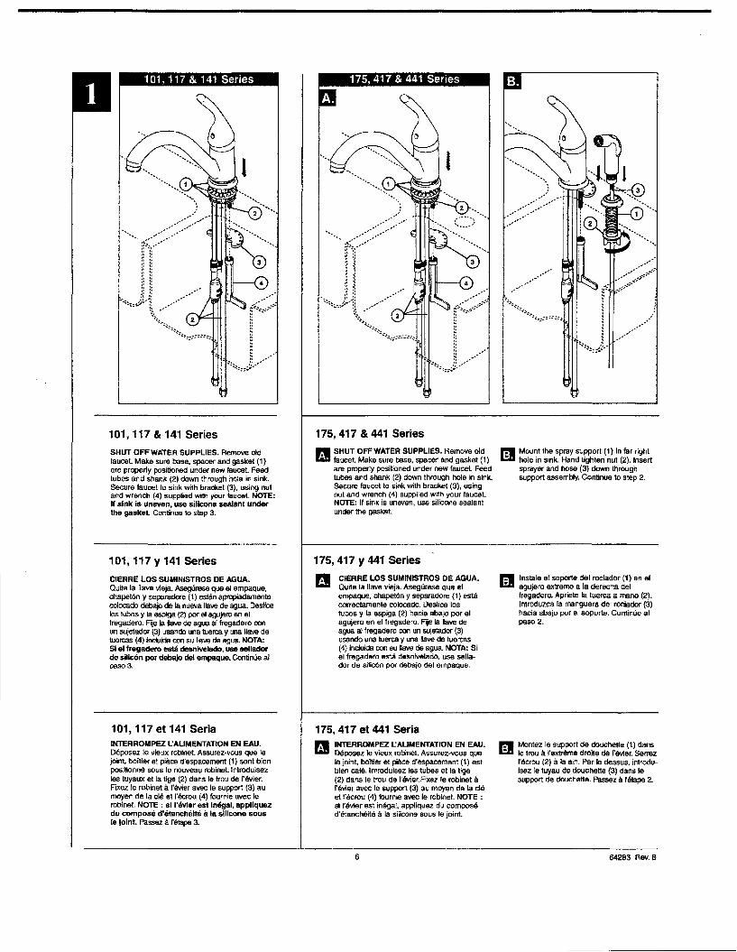
.••••••..••••~._••/__.:"":~r;II(;J]
.~~~~" , ..".. -........... '
...... r:·1i::::>······,I "
1! ;;
j~ ~~
~<'~'\::,:".~:;~~:::==::~
:
::::::::...........•.
................
. .
101,117 & 141 Series 175,417 & 441 Series
SHUT OFF WATER SUPPLIES. Remove oldfaucet. Make sure base, spacer and gasket (1)are property positioned under new faucet. Feedtubes and shank (2) down ll1rough hole in sink.Secure faucet 10 sink w~h bracket (3), using nutand wrench (4) supplied with your faucet. NOTE:If sink is uneven, use silicone sealanl underthe gasket. Continue 10 step 3.
... SHUT OFF WATER SUPPLIES. Remove oldIio:II faucet. Make sure base, spacer and gasket (1)
are properly positioned under new faucet. Feedtubes and shank (2) down through hole In sink.Secure faucet to sink with bracket (3), usingnut and wrench (4) supplied with yOur faucet.NOTE: II sink is uneven, use silicone sealentunder the gasket.
P.II Mount the spray support (1) in far rightI:::D hole in sink. Hand tighten nut (2). Insert
sprayer and hose (3) down throughsupport assembly. Continue to step 2.
101,117 Y 141 Series
CIERRE LOS SUMINISTROS DE AGUA.Qu~e la ilave vfeja. Asegurese que el ampaque,chapet6n y sepsradore (t) estBn apropiadamentecolocado debajo de Ie nueva ilave de agua, Desticelos tubas y Ia espiga (2) par Ell agujero en elfregadero. F~ Ia lIave de agua al fregadero conun sujelador (3) usando una tuert:a y una llave detuercas (4) incluida. con su Iiave de ague. NOTA:Si eI fregadeto estlI desniveledo, use selledorde sIllc6n par debajo del empaque. ContinUe aIpaso 3.
175, 417 Y 441 series
CIEARE LOS SUMINISTROS DE AGUA.Qu~e Ie lIave vieja. Asegurese que etempaque, chapel6n y separadore (1) estacorrecfamanfe colocado. Deslioe lostuboe y la aspiga (2) hacia abajo por elagujero en el fregadero. Fije Ie IIave deague aI fregadero con un sujetador (3)usando una tuarea y una !lave de fuareas(4) induida con su Dave de agua NOTA: Siel Iregadero ema de!lnlvelado, use sellador de silic6n por debajo del empaque.
I!II Instale el soporte del roclador (1) en el1:.11 agujaro extrema a la derecha del
lregadero. Apriele Ia tuerca a mano (2).Introduzca fa manguera del rocIador (3)hacia abajo por el soporte, Continue alpaso 2.
P.II Montez Ie s~port de douchede (1) clansi:B Ie trou Ii I'ext~ma droHe de fevler. Serrez
I'ectou (2) a Ie Bin. Par Ie dessus, introduisez Ie tuyau de douchede (3) dans Iesupport de douehatle. Pa~ Ii ftl1ape 2.
INTERROMPEZ I.:AUMENTATION EN EAlJ.Deposez Ie vieux robinet. Assurez'vous queIe joint, baTtier et pl/lce d'espacement (1) estbien cale, Inlroduisez las tubes et la tige(2) dans Ie trou de l'evier.Fixez Ie robinet Iifavier avec Ie support (3) au moyen de Ie cleet I'eerou (4) fournie avec Ie robinet. NOTE:sl feviar est in9gal, appllquez du composed'e!anehei19 Ii la silicone sous Ie joint.
175,417 et 441 Seria
B101,117 et 141 seriaINTERROMPEZ I.:AUMENTATION EN EAU.Deposez Ie vfeux rabinet. Assurez-vous que Iejoint, boilier at piece d'espacement (1) sont bIenpositionne sous Ie nouveau robinet.lntrodulsazIes lUyaux at la tige (2) dans Ie trou de f evfer.FlXez Ie robinet Ii I'evier avec Ie support (3) aumoyen de la ell! et I'ecrou (4) fournie avec Ierobinet. NOTE : 51 I'''vler est Intlgel, appllquezdu compose d'etBnct1eite;, III silicone SOU5Ie )01 nl. Passez Ii fatape 3.
6 64283 Rev.B

For Sprayer Models Only
... Pull on clip (1) unt~ disengaged. Pull down on dlverter plug (2) toraa remove. Discard diverter plug. Caution: Do not remove tube clip (3).
Para el rociador modela solamente
Hale el sujetador 0 gancho (1) hasta que se desencaje. Hale el tap6ndel desvlador (2) hacia abajo para sacarlo. Oescarte el tap6n deldesviador. Advertencla: No quite eI sujetador deltubo (3).
Pour Ie pUlverisateur modele seulement
Tlrez sur I'agrala (') jusqu'a ce qu'elle se libere. Tirez sur 1& bOllchon deI'inverseur (2) pour I'anlevar. Jetez Ie bouchon de finverseur.Attention: n'enlevez pas I'agrafe du lube (3).
Keeping cftp (1) disengaged, insart diverter hose and (2) Into olVertarhousing (3) until seated. Push In dip (1) until" snaps. Pull downmoderately to ensure connection has been made.
~ Mienlras que mantiene el sujetador (1) suelto, introduzC8 el extreme~ de la manguera con el desviador (2) en la annaz6n del desviador
(3) hasta que qUade reposado. Preslone el sujetador (1) hasta quequad& en sitio. Hale moderadamente hecla abajo para asegurar queIe conexi6n sa ha hecho.
~ Tout an malntenanll'agrale {1} ecartee, inlroduisez I'extrem"~ du1.::.11 tuyau souple de l'inverseur (2) dans 1& bollier de l'illV9rsaur (3)
jusqu'a ce qu'elle soit bien en place. Poussez sur fagrate {lljusqu'll ce qu'elle sa bloque en place. Tlrez ~rement sur Ietuyau pour vous assurez qu'il est bien raccorde.
64283 Rev. B

------- --------
OR
o
OU
:
Water Line Connections
B Ensure all frllings Br1d end connections are free ofdebris. Faucet fittings (1) are 318" compression, withenels colored red for hot and blue for cold. Loop tUbing(2) if it is too long. Nole: Recommended tubingminimum bend diameter Is 8". Secure metal nut (3)on faucet tuba 10 supply valve connection (4) and handlighten. then lighten one additionallurn with wrench.DO NOT OVERTIGHTEN. Repeat lor other lube.WARNING; Do not use pipe dope or other sealantson water line connections.
lEI Custom Fit Connections" you determine 1he PEl( supply tubing for thisfaucet Is too long and must be shorter to create an
B Conexlones a la Linea de AguaAsegurese que todos los accesorios Y las oonexionesfinales esten libres de residuos. Los accesortos (1) son decompresi6n cle 318-, con los elCtremos da color mjo para eIague caliente y azul para eI agua frfa. Enlace las tuber/as(2) si as rnuy large. Nota: La curva minima recomendadaee de 8" de dl6melro. Fije Ia tuerca de metal (3) en el tubade Ia ~ave de agua a la conexiOn (4) y apriete a mano, luegoapriete con una welle edicional con une ~eve de tuercas.NO APRIETE OEMASIAOO. Rep"a con al 0110 tubo.AVISO: No use compuesto para tuberfas u otrosselIadores en las conexiones de Is tuberia de egua.
lEI Conexlones EspecialesAVISO: SI usted determlna qua Ia tuberfs PEX para elsuminlstro de sgll8 para esta IISYe de ague es muy i8lglly debe necortarse para crear una Instalaci6n aceptable,asagtl........ leer las lnstrucelones y p1anlflque de
B Branchement a la tuyauterieAssurez·vous que tous las raccorcls sont exempts decorps ~trangers. Le branchement est effectue au moyenda raccords de robinetterie (t) 318 po Ii compression.L:extram1l8 du raccord lfeau chaude esl rouge eI celie duraccord d'eau lroide est b1eue. Faites une boucle avec Ietube (2) s'iI est trop long. Note: La dlamelre minimal dela courbure dolt 6tre d'au molns 8 po. V'tsSeZ I'oooumetallique (3), qui se trouve sur Ie tube du robinet sur 1eraccord du «lbinet d'a1imenlation (4) el serrez-Ie Ii Iamaln, puis laites un tour suppl6mentajr-e avec una ""'.PRENEZ GARDE DE mop SERRER. Raccordez I'autretube de Ie m4!me maniere. MISE EN GARDE: N'utillsazpas de pate ajoint nl d'autres prodults d'6!anchSlt8sur las raceords de tuyauterie.
lEI SpeciauxTuyauterie BranchementNOTIFICATION: 51 Ie tube d'atlmental1on en PEl( deee roblnet esllrop long eI dolt 8tre raccourcl, 1ise2
acceptable Installation, be sura to read 1heInstructions and plan ahead. When cutting thesupply tubing 1he Installer accepts the responsibilityto do so in a way that allows a leak-free lolnt to becreated. Delta Is not responsible for tubing that Is cuttoo short or cut In a Wtlf that will not allow for aleak-free Joint.For custom lit instaUations, you must use RP50952sleeves supplied with model and nuts included on supplylines. Tube cut must be straIght. See plastic sleeveinstallation instructions found in RP50952 and included in!his document for more lnlormalion.
Secure melal nut (1) on faucet tube to supply valveconnection (2) and hand lighten, than lighlen anadclitional2 turns with wrench. DO NOT OVERTIGHTEN.Repeat lor other tube.
antemano. Cuando corte Ie tuberfa de sumlnlslro eIInstalador acepta la responsebllldad de hacerlo deuna manera que pennlte crear una articulacl6n sinfiltraclones. Delta no S8 responsabnlza par lastuberfas que sa han cortado demaslado cortas 0cortBdas de una manem que no permite unaartIculac16n libra de III\raCI6n.Para instalaciones hechas a la med'Kia, ust9d debe usermanges RP50952 Induldas con el modelo y las tuercasincluidas en las tuberias cle sumlnistro. EJ corta del tubadebe ser recto, Vea las instruCCiones para la instaJaci6n deIa mBr1gB pl8slica inclulda con el RP50952 ypam masintormaci6n ineluida en este documento.Fije Ie tuerca de metal (t) en la tuberfa de Ie llave deague I gtifo a Ia conexi6n de la valvula de suministrn (2) yapriete a mano. Con Ia IIeve de tuareas, apriete Ia tuerescJandoie 2 vuenas mas da 51 tuera apretado 8 mano. NOAPRIETE DEMASIADO. Repita con fa olre tuberfe.
lee Instructions at prenez Ie temps de renechlr. Vowsdevez couper Ie tube de man"'re /I obtenlr un joint6!anche. Delta n'accepte aucune responsablmti slletube III til8 coupe trap court ou d'une maniere quiempeche Ie JoInt d'etre etanche.Dans Ie cas des installations sur mesure, vous devezuti~se< les menchons RP50952 Ioumls avec Ie robinet atIes scrous qui sa lrouvant sur las arrivees cI'eau. Le tubedon 8tre coupe d'equerre. Pour obtenir plus derenseignements, veuillez consulter Ies instructionsd1nstaJIIltions des manchons an plaslique qui sa lroUventdans Ie k1t RP50952 et qui sont inclusas dans Iepresent document.Vissez I'ecrou melallique (t), qui se trowe sur \e tube durobinet, sur Ie raccord du robinel d'a1imentation (2) atserraz-Ie II fa main. Serrez·le Ii la meIn, puis fattes deuxtours Ii I'aide lfune cle. PRENEZ GARDE DE TROPSERREA. Raccordez I'autre tube da Is merna maniere.
8
Potential Problems and Remedies
• TUbing Is not cut perpendlcular to 1he axis 01 thetube; carefully make an additional cuI. being carefulnot 10 cut the lube 100 short.
• Tubing Is cut too short: buy a coupling union and areplacement supply line that mata together 1mm estore. The coupling union and intended to connect tothe faucet must mate to the standard 318"connection nllls and plastic sleeves supplied with!he faucet.
• The plastic sleeve or connection nut Is lost:purchase a repIacemenl nut and/orpIasIic sleeve lhaIare desigl9d to seal with PEX tuOOg. NOTICE: DONOT use a ..-lsIellv6,RP51243gas1cet(supplledwtth faucet) or f8frWe In the place of1he plasticsleeve suppled, It may not create a leak..free joint.WARNING: 00 not use pipe dope or othersealants on water line connections.
Problemas POtenclllles YSotuclones• La iuberia no eslli cortada perpendicular al eje del
tubo; cuidadosamente hags un corta adlcional,tenlendo cuidado de no COrlar el tubo demasiado corto.
• La tuberIa est1i eortada demaslado corta: compre enun almacen un acopIamienlo de uni6n y una tuberfa desuministro de repueslo que acoplen. EI extreme de fauni6n de eeopIamienlo que as para conadar e Ia lIave deague debe acoplar con las tuerl:as ast8ndares de 3/8" Ymangas de pl8stico Incluidas con fa lIave de ague I goo
• La mange pl8stlca 0 la tuerca de conexJ6n ee haperdido: compre una tuerca cia repueslo y/o mangep1l1slica diseiiada para seliar ccn Ia tuberfa PEX.AVISO: No use una menga de metal, RP51243empaque (sumlnlstradocon" grllo) 0 casqullo,envel de Ia menga Inciulda puede no crel!II' unaerticulaci6n sin IitracI6n. AVISO; No use compuestopara tuberlas u OIroS selladores en las conaxlones de la tuberia de agua.
Problemas po&slbles eI correctifs• L.e tube n'est pas sectlonne perpendlculalrernentason ax. : Faites une nouvelle coupe en pranant
garde de ne pas lrap raccourcir Ie tube.• Vous avez coupe Ie tube trop court: Achelsz un
raccord-union at un tube d'arrivee d'eau de rechangedans un magasin,LCextr9mi16 clu raccord-union Ii!Becorder au robinet doil t\tre COITlp>tIlbie avec lesscrous 3/8 po standard elles manchons en plasliquafoumis avec Ie robinet.
• Vous avez perdu un manchon en plastlque ou unecrou de raccordement : Achelez un 6i:rou eVou unmancoon en plastique conl;US pour former un (BCCOI'datanche avec un tube PEX. NOTIFICATION: Evltezd'utlilser un manchon metalllque, RP51243 Ie Joint(Ioumle avec Ie roblnet) ou une vlrole a la placedu manchon en plastlque IoumI. La ~ntne serepas etanche. MISE EN GAROE : N'uli~a depAt. a joint nl d'lllutre6 prodults d'6ta surlee raccords de tuyauterie.
64283 Rev. B

Correct methodMetodo CorrectoBonne methode
Incorrect InstallationInstalaci6n IncorrectaInstallation Incorrecte
Do not install sleeveupside down.
Ensure cui is straight
Custom Fit Connections - Plastic Sleeve Installation Instructions
1. Identify desired length 01 tube (1). leave l' - 2' at extra length 10 allow for easierinstallation and cutluba. Ensure cuI is straighl end burr tree.
2. 8"de nut (2) and plastic sleeve (3) onto cut tuba. Ensure sleeve is oriented as shown.
3. Insert tube inlo oultel filting (4). Tube should touch bollom of hole Inside fitting.
4. Slide plastic sleeve down tube until II engages top of filling, NOTICE: Failure to useplastic sleeve In the correct orienlellon will result In disconnection and possiblewater damage.
5. Slide nul over plastic sleeve. Wrth wrench, tlghlen nut 2 turns past finger light
Conexiones Especlales - Instructions d'installations de Ie manchonen plastique
1. Iderrtlflque la longilud deseada del tubo (1). Deje 1"- 2" de so"ura para una instalacl6n masfaeil y sin rebabas. Asegure que 91 corte sea recto y sin rebabas.
2. Resbale la tuerca (2) y la manga plas1ica (3) sabre el tuba cortado. Asegure la manga saorienta segun 10 demoslrado.
3. Introduzca el tuba den1ro del accesorio (4). EI tubo debe toear el fonda d91 agujero dentrodel accesorio.
4. Deslice Ie manga plastics hacie abajo en eltubo haste que encaje ella parle superior delaccesorio. AVISO: EI no usar la manga phistlce en la orlentaci6n correcta resultara endesconexl6n y poslble dallo por agua.
5. Deslice la lUerca sabre la manga plastica. Con la Ilave de tuercas, apriele la tuerca dB.ndole2 vueitas mas de si fuera apretado a mano.
Speelaux Branchement - Instrucciones para la Instalaci6n dellaManga Phistica
1. Idenlifie2 Ia longueur deslree du tube (1 ).leissez 1 il 2 peuees de la longueursupplementaire pour taciliter !'installation et coupez Ie tube. Faites une coupe d'equerre alenlevez les bavures.
2. Glissez I'ecrou (2) ella manChon en plastique (3) sur Ie tube coupe. Assurez Ia manchonest oriente comme montre.
3. Introduisez Ie lube dans Ie raecord (4). Le tube dort toucher Ie fond du troo a Finterieurdu raccord.
4. Faites gllsser Ie manchon en plastique dans Ie lube jusqu'a ce qu'li penetre dans la pertiesup9rieure du raccord. NOTIACATION : SIIe manohon en plasUque n'a pes ete Installedans I'orientatlon correcle,le reccord paut se de/eire at I'eao peUl occeslonnerdes dommeges.
5. Fanes glissar I'ecrou sur Ie manchon en piastique. Serrez-le Ii Ie m8in, puis faites deux lours aI'aide d'une cll\.
9
No Instale la mangabocaabajo.
N'installez pas Iemanchon a I'anvers.
[LOr. ij II i
@~
Do not use RP51243 gasket(1) supplied with PEX tubingor brass /emule (2) suppliedwith valve slops.
No use RP51243 empaque(1) suministrado con elluberfa de PEX 0 el casquillode bronce (2) suministradocon las valvu las de cierre.
N'UlIIi~ pas RP51243 Iejoinl (1) Iournie avec Ia IUyautene de PEX ou Ie bagueen cuivre (2) fournie avec Iesrobinets d'arri'll.
Asegurese que el corteeste~.
Assurez·vous queIa coupe est drolle.
Ensure lube is fully insertedinto SlOp before Sliding sleevedown to engage top oIlitting.
Asegurese que ellubo eslecompletamente introducidodentm del lope anles dedeslizar Ia manga haciaabajo para encajar Ia partesuperior del aecesorio.
Assurez-vous que Ie lubeesl introduit entieremenldans Ie robinet d'arr!!avant de 18ire gllsser Iemanchon vers Ie bas pourIe her II Ia partiesuperieure du raccord,
64263 Rev, B

------------------------------------------
2
~I (:'::~i-/(::·:)I
H
Pla~ant I'arret de limite de poignee (facultatif)Ce robinet est mimI d'une butee de temperalure maximale Ii deux positions. La positionI, Ii gauche, parmet Ie deplacement de Ie manette entre lee deux extremites de 19plage de temperature (eau tres lroide at eau Ires chaude). cast Ia poMlon selectionn~ en usine. La position 2, Ii droite, pennet Ie deplacement de la manette sur la mo~ie
de Ia plage de temperature (eau tres !roide el sau mitigee).II est possible de ffigler Ie butes de temperature rnaximale de Ia manette au moment deI'installation du robinet Un rllglage il. Ie position 2 peul empeeher rebouinantage parceque celte position Iimile la quantile d'eau chaude dans Ie melange. Toutefois, ce ffiglagede la butes de temperature maximale de la manette no conS1itue pas une garantie absoIue contre f<ibouillanlage parc-.e qu'il n'oflre aUCUM protection contra les fluctuationsde Ia pression d'alimenta1ion ou les chengements de temperature soudains.
Pour modnler la position de la but~de temperature maximale de la manette : enlevez Ie manelte; amenez I'obturateur Ii I'extremite de la plage du cOle eau Irolde pourfaire s'ecouler I'eau; modiliez Ia pos~ion de la buleo de temperature maximaIe; lermezIe robinet; reinstallez la manette.
Setting The Handle Limit Stop (Optional)This faucet includes an integrated handle lim~ stop that has two pos~ions. PositionI, to the left, allows full handle motion (the full range between "all cold' to "all hot").The faucet is set in position 1 in the factory. Position 2, to Ihe right, allows haff of thenonnal handle motion ("all cold" to "mixed hollcokf').The handle lim~ stop can be adjusted by the homeowner once the faucet Is Installed.selling the handle lim~ stop In pos~ion 2 may help to prewnt scalding because itI;m~ the amount 01 hot water in the mix; however, this handle limit stop will not alwaysprevent scalding because ~ does not compensate lor incoming pressure or suddenwater temperature changes.
To change p06ltlons of the handle limit 6top: remove the handle; move the wivestem 10 the all cold position so the water is on; change the posltlon 01 the handle limitstop; tum off the water; reinstall the handle.
Fljando la parada de limite de la manija (opcional)Esta lIave de agua !nduye una manija integrada., que tiere doe posiciones, pera IimMr latemperatura. La posiciOn 1, ala izquierda, permlte eI movimiento complelo de Ia manija(el aJcance completo entre eI agua "1otalmente Irla" hasla "1otalmenta caliantej. Lafabrica preselecciona Ia Jlave de agua (grilo) a Is poeici6n 1. La posici6n 2, a Ie denecha,permlte la m!lad del alcance de mOllimiento normal de Ia manija ("tolalmente tria" a Iaposici6n "mixia calienleJfrla").
Una vez que la lIave de egua (groo) se ha instalado, ellfmite rolacional de la manijapuede ajustarse por el propietario de la residencia. Ajustando la manija de ajuste deltope dellimile de la temperatura a la posici6n 2 puede ayudar a prevenir escaldadurasporque limita Ia cantidad de agua caliente en la mezcla; sin embargo, asta manija quelimM Ie temperatura del agua no siempre prewndnl. escaldaduras porque no compensala presion del agua de entrada 0 cambios repentinos de la temperatura del aguaPara camblB1" las posfclones de la manlJa que Ilmllan la temperatura: qUM la manija;carrb!e Ia posici6n de la espiga de la valvula a la posici6n tolalmente Irla de manera queel agua esle abierta; carrbie la posici6n de la manija. que limlla la temperatura; cierre elagua; reinstate Ie. manija
.~...~~~
....-:1,.$r1:?
~.•..., \\\
{)
'.'.
PURGEZ L'INSTALLATION:... Retlrez I'aerateur (1) at placaz la poign~ (2) du robinet erLiD pos~ion d'ecoulement maximum de I'eau chaude el de I'eau lroide.
Retablissez I'alimentation en eau chaude et en eau lrolde (3) etlaissez couler I'eau pendant une minute. Imporlent: Ie fait delalsser couler I'eau pennet d'evacuer les corps etrangen;qui pourralent abimer lea composants Internes du roblne\.Reinstallez I'aerateur.
P.!II Wrifiez qu'il n'y a pas de fu~es aux fleches. Resserrez leeL:II raccords au besoin, mais prenez garde de trop serrer.
DEJE CORRER EL AGUA POR LAS TUBERiAS:
... Quite al aereador (1) Y mueva la manija de la lIave de agua (2) aI.i.II la posici6n completamente abierta. Abra los suministros de agua
caliente y Iria (3) y deje correr en agua por la Iineas por un minuto.lmportente: Esto llmpla cualquler escombro que puedacausar dano a las partes Internas. Reinstale el aereador..
~ Examine si hay fl~raciones en todas las conexlones indicadasL:II con flechas. Apriete de nuevo si as necesario, pero no
apriate demaslado.
FLUSH YOUR SYSTEM:
... Remove aerator (1) and tum faucet handle (2) to the full on mixedI.i.II position. (Some models require wrench (3) to remove aeretor.)
Turn on hot and cold water supplies (4) and flush water lineslor one minute. Important: This nushes away any debrls thatcould cause damage to internal parts. Reinstall aerator.
~ Check all connections at arrows lor leaks. Ae-tighten if necessary,I:D but do not overtighten.
to 64283 Rev. B
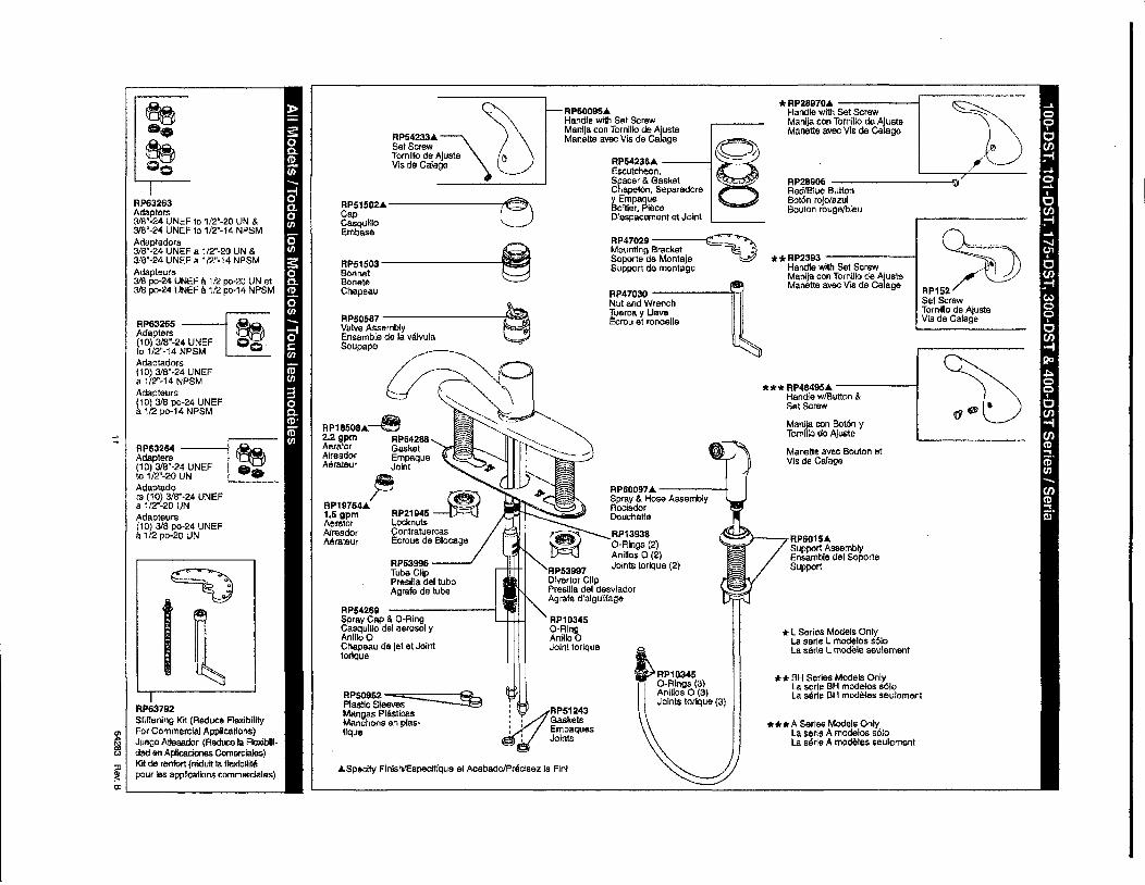
~AP152/SetScrewTornillo de AjusteVis de Calage
RP2890S ----------;0"RedlBlue Bullon80t6n rojo/azulBouton rougelbleu
*RP28970. ------1Handle with Set ScrewManlja con Tornillo de AluataManette avec Vis de Calage
* L Series Models OnlyLa serle L modelos s610La serle L modele SButernent
**BH Series Modals OnlyLa serle BH modeloa 8610La sMe BH modeles aeulemenl
Manette avec Bouton alVis de Calage
**RP2393 -------1Handle with Set ScrewManija con Tornillo de AjuslBManette avec VIS de Calege
***A Serlee Models OnlyLa serle A modelos 0010La serle A rnodeles seulemenl
*** RP4849SA.. -------1Handle w/Bulton &SetScrew
Manila con Bo16n yTomfilo de Ajuste
r"O:.='''---RP601S.Support AssemblyEnsemble del SoporteSupport
o
~RP10345.' ' o-RI"gs (3)
Anillos 0 (3)Joints torlque (3)
§~w'~'RP5423SA.. ----IEscutcheon•Spacer & GasketChapet6n. Separeoorey EmpaqueBoltler. PieceD'espacement at Joi"t
RP47029 ----i~~-,..~."Mounting Bracket .Jc~Soporle de MontajeSupport de montage
RP60097. -----tSpray & Hose AssemblyRociadarDouchalle
RP13938O-Rings (2)Anillos 0(2)Joints lorlque (2)
RP47030 ------trNul and WrenchTuerca y UaveEcrou el rondelle
RP60095.Handle wi1h Set ScrewManila con Tornillo de AjusteManette avec Vis de Calage
RP10345O-RingAnilioOJoint torique
W·, RP51243:. Gaskets: I Empaques
: Joints
RP50952~Plastic SleevesMangas PliisllcasManchons en plas-lique
RP54289Spray Cap & a-RingCasquilio del aerosol yAnJlIo 0Chapeau de jel el Jointtorique
.Speclfy FlnlshlEspeclflque el AcabadolPraclsez Ie Flnl
RP54233.~JjSetScrewTornillo de Ajuste 0Vis de Calage
RP53996Tube ClipPresHla delluboAgrafe de lube
RP51502.t.--------e>::,:--~CapCasquilloEmbase
--!~-RP51503BonnetBoneteChapaau
RP50587 ~Valve Assembly ~
Ensemble de la valvula _
S"~~ ~';
--....., -~ ---.....
RPl8508A..~ "2.2 gpm RPS4288Aerator GasketAireador EmpaqueMrateur Joint '.JI>
RP19764~ ~1.5 gpm RP21945--IJ-:::-~Aerator LocknutsAireador ContratuercasMrateur I::crous de 81008ge
1RP63792Stiffening Kit (Reduce AexlbilltyFor Commercial Applications)Juego Atlesador (Reduce Ia FlexibUldad en Aplicaciones Comerclales)KIt de renlort (r8dun la tlexlbHltepour Ies applications commarclales)
RP63263Adapters3/8"-24 UNEF to 1/2'-20 UN &318"-24 UNEF to 1/2'-14 NPSMAdaptadors3/8'·24 UNEF a 1/2"-20 UN &318'-24 UNEF a 1/2"-14 NPSMAdapteurs3IB po-24 UNEF II 1/2 po·20 UN et3/8 po-24 UNEF 111/2 pO·14 NPSM
RP63265 ----IAdapters(10) 3/8'-24 UNEFto 1/2"-14 NPSMAdaptadors(10) 318"·24 UNEFa 1/2"-14 NPSMAdapteurs(10) 318 po-24 UNEFIi 1/2 po-14 NPSM
RP63264 ----I~Adapters(10) 3/8"-24 UNEF 0_to 1/2"-20 UN ,_
Adaptadors (10) 318"·24 UNEFa 1/2",20 UNAdapteurs(10) 3/8 po-24 UNEFa 1/2 po-20 UN
~lJlL- _
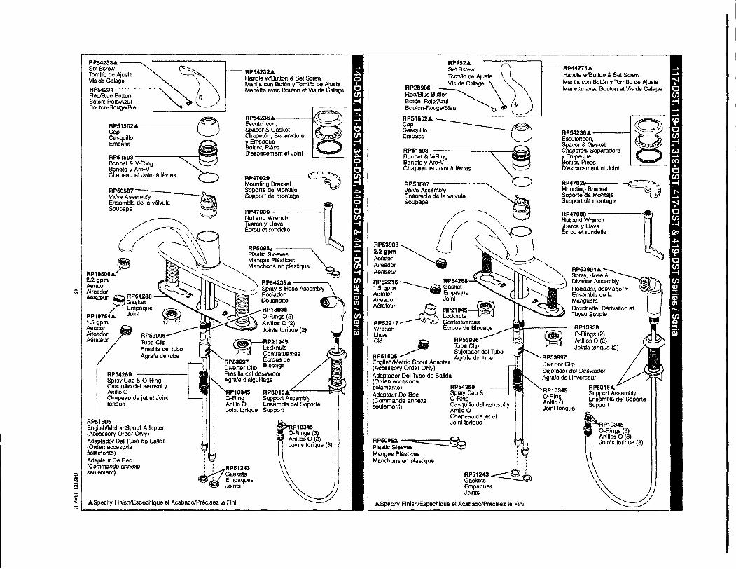
RP447714Handle wIBulton & Sat ScrewManija con BotOn y Tornillo de AjusteManette avec Bouton et Vis de Calage
RP54236. -----IEscutcheon,Spacer & GasketChapet6n, Separadorey EmpaqueBomer, PieceD'espacemont et Joint
RP470~Mounting Bracket -- •Soporte de Montaje - •Support de montage
RP47030------fllfillNut and WrenchTuerca y WaveI::crou et rondalle
RP10345O-RingAnIlIoOJoint torique
RP53997Dlverter ClipSvjetador del DesviadorAgrale de ('inverseur
RP601S.Support AssemblyEnsemble del SoporteSupport
RP53994.Spray. Hose &Diverter AssemblyRociadar, desvlador yE:nsamble de IeMangueraDouchette, Derivation etTuyau Souple
____~~-----fIP13938O-Rings (2)Anlllos 0 (2)Joints relique (2)
,,,..RP51243 ----e l..Gaskets~EmpaquesJoints
RPS3998Tube ClipSujelador del TuboAgrafe du tube
RPSD587Valve AssemblyEnsemble de Ie W1vulaSoupape
::t1~~~W ~Tomillo de Ajuste
RP28906 Vis de Calage :\RadIBlue ButtonBo16n: Aojo/Azul GBouton-RougeIBleu
RP51502.~-.Cap __Casquillo -Embase
RP515D3Bonnet & V.RingBonete y Aro-VChapeau et Joint e. levres
RP50952 ~Plastic SleevesMangas Plllsli<:asManchons en plastique
• Specify Flnish/Especfffque el AcabaclolPreclsez Ie Flnl
RP63998~1 rc-~-,)=i72.2 gpm J ("-'Aerator '-.Aireador ----A8rateur ..:'---...
RPS2216~ RP64288 -..::---....1.5 9pIn GasketAerator EmpaqueAireador Joint ~Aeraleur~ RP21945 •
, LocknutsRP52217 ContratuercasWrench Ecrous de BIOO8geL1aveChi (iiJ
APS1505~EnglishIMetric Spout Adapter(Accessory Order Only)Adaplador Del Tuba de Salida(Orden accesortasolamente) RP64269Adapteur De Bee Spray Cap &(Cornmande annexa O-Ringseuiement) CasqUlllo del aerosol y
AnilioOChapeau de jet atJoint tonque
RPS09S2 -----".Plastic SleavesMangas PhisllcAsManchons en plastique
RPS4236.-----IE:sculcheun,Spacer & GasketChapet6n, Separadorey EmpaqueBollier, PieceD'espacemenl et Joint
RPS4232.Handle wlButton & Sat ScrewManlja con Bol6n y Tornillo de AjlJsteManella avec Bouton at Vis de Calage
RP47D29-----t:C=~?Mounting Bracket 'VSoporte da MontejeSupport de montage
RP47030 ------11Nut and WrenchTuerca y Uave~crou at rondolle
.,,
~:: RP51243
" ~~k:~~esJoints
RP5423S.---~Spray & Hose AssemblyRociadorOouchetta
_, RP13938#> ..~ O-Rings (2)..........~ Anillos 0 (2)
___-1..~~ Joints torique (2)
~. RP21945
"_ Locknuts• Conlratuercas
RP639Il7 Ecrous deDlverter Clip BlocagePresIlia del desvladorAgrafe d'aiguillage
RP53998lUbe ClipPresllla del tuboAgrate de lube
RP50587=::;::-------S-.__Yalve AssemblyEnsamble de Ie valvulaSoupapa
RP54233.SetScrew ~
Tornlflo de Ajuste J'bVis de Calage
RPS4234----~~RedIBlue Button "Bot6n: RojolAzulBouton-RougelBleu
RPS1502.lo.------...,~Cap ~CasquilloEmbasa
RPS1S03 -----..,...---t--:lBonnet & V-RingBonete y Aro-VChapeau et Joint a levres
.Specify Finlsh/Especiflque el AcabadolPrecisez Ie Flnl
RP51505EnglishlMelric Spout Adapter(AcceS60IY Order Only)Adaptador DellUbo de Salida(Orden accesorJasolamente)Adapteur De Bee(Ccmmande annexaseuiement)
RP54269Spray Cap & O-RingCasquillo del aerosol yAnilioOChapeau de jet at Jointtorlque
RPl8508.~2.2gpmAeratorAlreadorAerateur~ RP64288
GasketEmpaque
RP19754. Joint1.5 gpmAeraterAireadorAtlrateur
~&1'"JJ
~o:ll.- _