ttl series - cmz.comfanuc servo motor for turret indexing. integrated spindle motor for driven tools...
TRANSCRIPT
Turning the world
TTL SeriesTTL 52 / TTL 66 MODELS
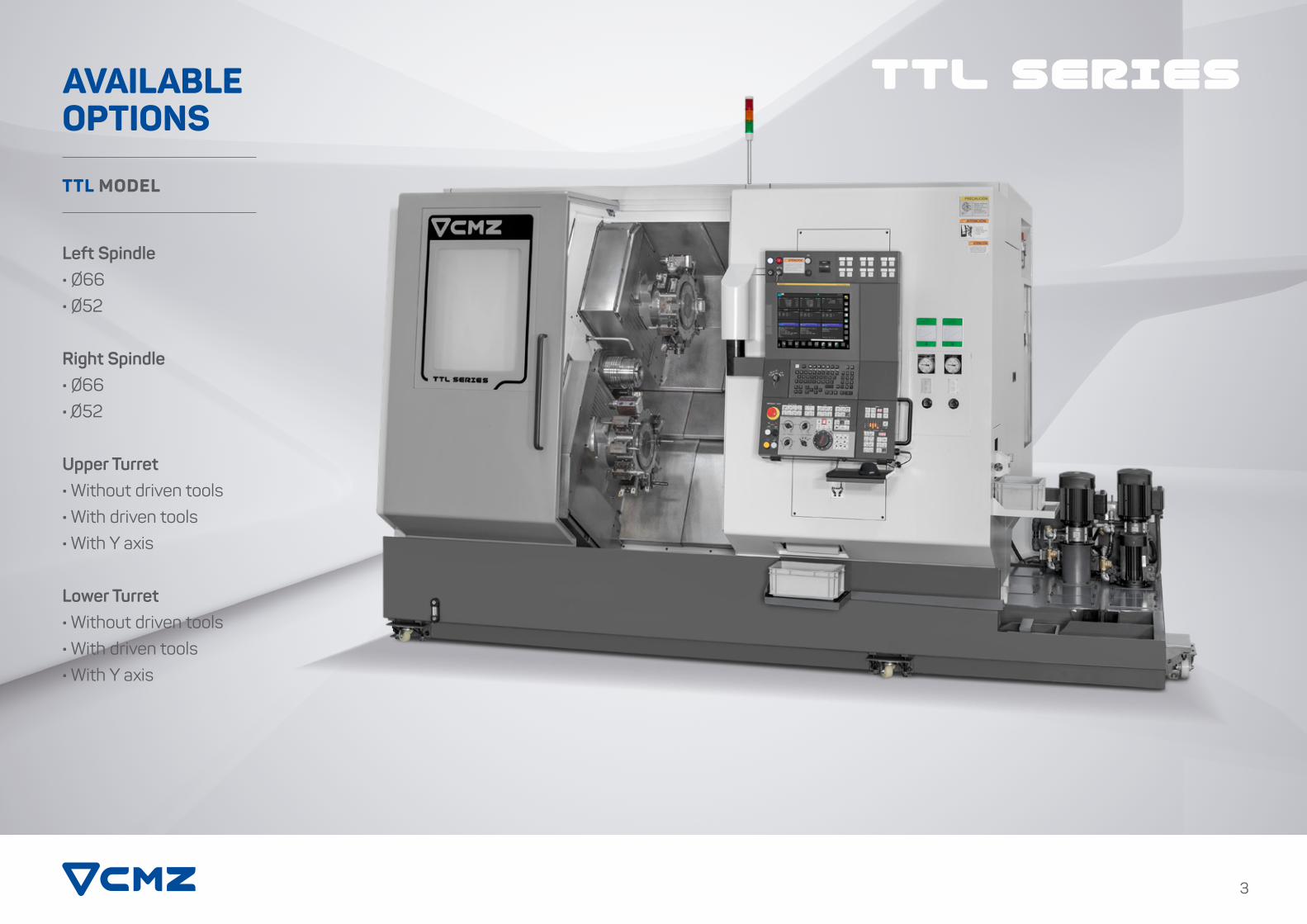
AVAILABLE OPTIONS
Left Spindle· O66· 052
Right Spindle· 066· 052
Upper Turret· Without driven tools· With driven tools· With Y axis
Lower Turret· Without driven tools· With driven tools· With Y axis
TTL MODEL
3
TTL SERIES

TECHNICAL CHARACTERISTICS
5
TTL MODEL
TTL SERIES· Y axis integrated spindle motor· Direct drive· Oil-cooled
FANUC Servo Motor for turret indexing.
Integrated spindle motor for driventools 14 Kw, 42 Nm, 12,000 rpm
Oil-cooled turret.
Integrated spindle synchronous motor
Synchronous motor allows faster acceleration and deceleration than traditional motors. Oil-cooled.
Roller bearings used in spindle.
FANUC Servo Motor for turret indexing.
· X axis integrated spindle motor· Direct drive· Oil-cooled
Machine without belts. Direct drive for all motors.
· Y axis integrated spindle motor · Direct drive· Oil-cooled
· X axis integrated spindle motor· Direct drive· Oil-cooled
Turret clamped withcurvic coupling.
Controls the temperature of the oil that cools:
• The spindles.• X and Y integrated spindle motors.• X3 axis ball screw mounts.• The turrets.
Thermal sensor in the bed
Removable, separate coolant tank, guarding design prevents coolant contact with the machine bed ensuring thermal stability.
The coolant tank can be removed without removing the chip conveyor.
Highly rigid cast iron 60º MONOBLOCK.
· X3 and Z3 axis sub-spindle.· Fanuc Option <Compound Machining>
Motor mounting cooled with oil.
Ball screws mounted at bothends and pre-stretched.
Ball screws with automatic lubrication.Roller type linear guides. Turret clamped withcurvic coupling.
Roller bearings used in spindle.
Integrated spindle synchronous motor
Synchronous motors allow
faster acceleration and deceleration than traditional motors. Oil cooled.
Integrated spindle motor for driven tools 14 Kw, 42 Nm, 12,000 rpm
Oil-cooled turret.

INTEGRATED SPINDLES WITH SYNCHRONOUS MOTORS
· SPINDLE REMAINS COOL · REDUCED THERMAL EXPANSION· SUPERIOR PRECISION
TTL SERIEs
POWER AND TORQUE DIAGRAMS
ACCELERATION TIME REDUCED BY HALF
Special coolant collectiontray manufactured by CMZ
· Excellent access to adjust the detectors.· Easy chip removal.· Protection against coolant entering into the hydraulic circuit.
Hydraulic brake on C axis.
Synchronous motor
Acceleration time reduced by half.
Built-in encoder. Compensation of mensuration errors by laser measurement and bidirectional and interpolated error correction.
Double row of roller bearing that canwithstand substantial impacts
without damage.
Greater rigidity,accuracy and
durabilitySpindle and bearingscooled by oil.
35,5
28,3
23,5
5000375022502000
205
Nm
1500
TTL-52
500 1000 2500 3000 3500 4000 4500
150 N
m
180 N
m
35,5 kW (Max.)
10
15
20
25
5
30
(kW)
(rpm)
1000 2000 3000 4000
0,751
1,4
2
3
3,9
TTL-66 vs TX-66
TX-66TTL-66(seconds)
(rpm)
2,2
0,250,53
1,73
0,99
Acc
eler
atio
n ti
me
4
50%Reduction
28,3 kW (S3-25%)
23,5 kW (S1)
1000 2000 3000 4000
0,781
1,35
2
32,92
TTL-52 vs TX-52
TX-52TTL-52(seconds)
(rpm)
2,02
0,125
0,53
1,30,845
Acc
eler
atio
n ti
me
4
50%Reduction
5000
0,2850,46
No pulleys or belts
• No belt slippage• Better surface finish• Lower noise level• Less maintenance
Hydraulic cylinderat 45kg/cm2
• More compact(Reduced cross-section means higher clamping speed)
• Greater sensitivity for light clamping
28,3
23,5
3500
2750
28,3 kW (S3-25%)
23,5 kW (S1)
2500
205
Nm
1500 4000
500 1000 2000 3000
5
10
15
20
25
30
(kW)
(rpm)
35,535,5 kW (Max.)
TTL-66
180 N
m
150 N
m
7

TURRET WITH12,000 rpmDRIVEN TOOLS
TTL SERIEs
9
Built-in motor for driven tools
Decreased vibrations at higher spindle speeds.
Motor and turret cooled with oil
Allowing driven tools to work continuously at 12,000 rpm (S1).
12,000 rpm driven tool holders
CMZ manufacture their own tool holders. 12,000 rpm with internal cooling.
Hydraulic Clamping
Turrets hydraulically clamped with curvic couplings for accurate indexing and rigidity.
Fanuc servomotor changes turret position in only 170 milliseconds
The turret indexes one position (30º) in 170 ms and rotates 6 positions (180º) in 400 ms.
Standard tool holder N-55
N-55 is a popular standard toolholder.
.
4000
14 kW (Max.)
11 kW (S6-15%)
10 kW (S1)
32 N
m
3000 8000
10
2
4
6
8
12
14
11
12000
(Kw)
(rpm)
POWER AND TORQUE DIAGRAM OF DRIVEN TOOL MOTOR
42 N
m35
Nm
The turret changes a position (30º) in 170 msand indexes to the furthest position (180º) in 400 ms
This means an indexing time 40% fasterthan the previous model (TX-Series)
Indexing time
170 ms40% faster
TTL-66TX-66
400 ms
170 ms
30º
180º
270 ms
30º
550 ms
180º
POSITIONS24

30 m/minin all axes
X AND Y AXIS INTEGRATED MOTORS AXIS ENCODERS DIRECTLY ATTACHED TO THE BALL SCREW
TTL SERIEs
Thermal stability and precisionX and Y axis without belts and oil-cooled
Linear Encoder (Optional)
Linear encoders are optional on all axes.
X and Y axis integrated motors
Without belts for increased accuracy.
Roller linear guides
Roller linear guides on all axes that provide great rigidity and vibration damping.
Pre-stretched ball screws
Pre-stretched ball screws mounted at both ends give the machine greater thermal stability.
Rigid and compact design
Encoders directly mounted to the ball screw
Without belts for increased accuracy.
45 mm
Y axis travel

8 SecondsTotal time for
component collection
PNEUMATIC PARTS CATCHER
TTL sERIEs
13
Option 1:Component gripper
The gripper has a pneumatic opening and closing movement.
Downward movement regulation stop
The catcher pivots and a downward movement is performed to clamp the part.
Pick up
The bar feeder pushes the remnant into the collector box, which is mounted onto one of the positions of the bottom turret.
Transfer to the catcher
The turret rotates to a position where the remnant then rolls into the catcher.
Remnant eject
The catcher withdraws back to its home position and the remnant exits machine.
ACCESSORY FOR REMNANT COLLECTION
Option 2:Component collector
The collector has a pneumatic opening and closing movement.
1
2
3
Finished parts conveyor
The conveyor moves finished components to the outside of the machine.
*
* Could be higher depending on the type of component being collected.
TTL SERIEs
15
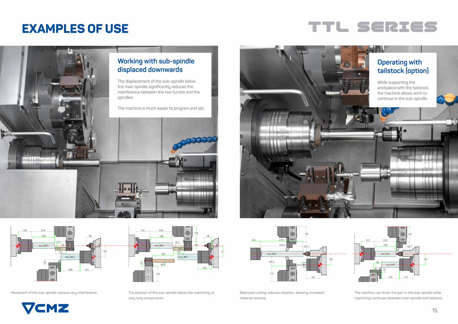
Operating with tailstock (option)
While supporting the workpiece with the tailstock, the machine allows work to continue in the sub-spindle.
Balanced cutting reduces vibration, allowing increased
material removal.
The machine can finish the part in the sub-spindle while
machining continues between main spindle and tailstock.
EXAMPLES OF USE
Working with sub-spindle displaced downwards
The displacement of the sub-spindle below the main spindle significantly reduces the interference between the two turrets and the spindles.
The machine is much easier to program and set.
Movement of the sub-spindle reduces any interference. The position of the sub-spindle allows the machining of
very long components.

TTL SERIEs
Drill simultaneously using the 2 spindles without
programming limitations.
Any shape can be turned in the sub-spindle, while the same turret
works on the main spindle.
3 tools working simultaneously
EXAMPLES OF USE
The large travel of the sub-spindle allows simultaneous
working with 3 tools in varied conditions.
The third CNC channel gives the flexibility to program multiple
applications using 3 tools simultaneously.
Working with 2 turrets and 3 channels
17
19
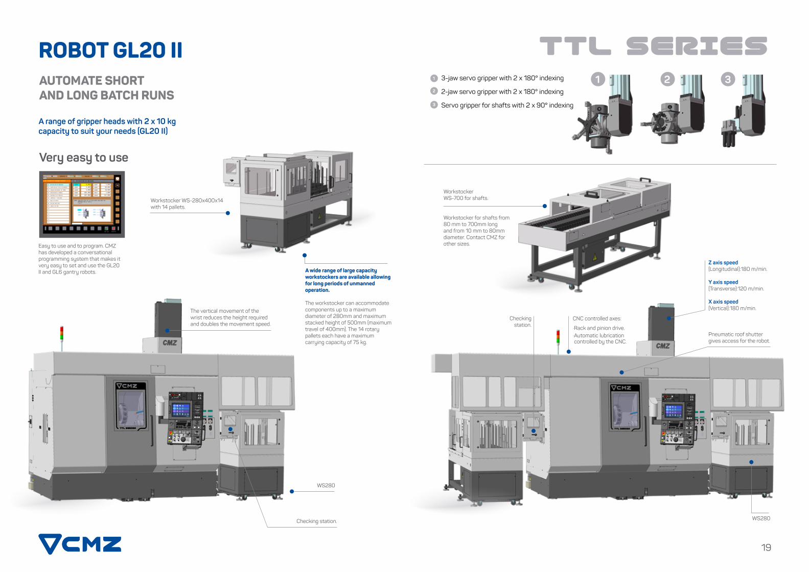
3-jaw servo gripper with 2 x 180° indexing
2-jaw servo gripper with 2 x 180° indexing
Servo gripper for shafts with 2 x 90° indexing
WorkstockerWS-700 for shafts.
Workstocker for shafts from 80 mm to 700mm long and from 10 mm to 80mm diameter. Contact CMZ for other sizes.
Z axis speed(Longitudinal):180 m/min.
Y axis speed(Transverse):120 m/min.
X axis speed(Vertical):180 m/min.
CNC controlled axes:
·Rack and pinion drive.·Automatic lubrication controlled by the CNC.
Checking station.
Pneumatic roof shutter gives access for the robot.
WS280
1 2 3
TTL SERIEsROBOT GL20 IIAUTOMATE SHORT AND LONG BATCH RUNS
A range of gripper heads with 2 x 10 kg capacity to suit your needs (GL20 II)
Very easy to use
Easy to use and to program. CMZ has developed a conversational programming system that makes it very easy to set and use the GL20 II and GL6 gantry robots.
The vertical movement of the wrist reduces the height required and doubles the movement speed.
Checking station.
WS280
A wide range of large capacity workstockers are available allowing for long periods of unmanned operation.
The workstocker can accommodate components up to a maximum diameter of 280mm and maximum stacked height of 500mm (maximum travel of 400mm). The 14 rotary pallets each have a maximum carrying capacity of 75 kg.
Workstocker WS-280x400x14 with 14 pallets.
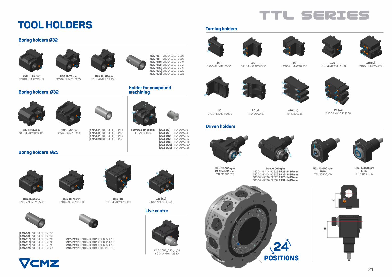
TOOL HOLDERS TTL SERIEs
Ø25-H=55 mm 310.04.NKM0112500
Ø25-H=75 mm 310.04.NKM0112520
Ø25 (X3) 310.04.NKM0211000
Boring holders Ø32
Ø32-H=55 mm310.04.NKM0113220
Ø32-H=75 mm310.04.NKM0113200
Ø32-H=80 mm310.04.NKM0113240
Boring holders Ø25
Ø32-H=75 mm 310.04.NKM0113201
Ø32-H=55 mm 310.04.NKM0113221
310.04.BLCT3210 310.04.BLCT3212 310.04.BLCT3216 310.04.BLCT3225
Boring holders Ø32
Ø25 (X2) 310.04.NKM0142500
310.04.CPT_D25_4_01310.04.NKM0112530
Turning holders
Driven holders(Ø32-Ø10)(Ø32-Ø12)(Ø32-Ø16)(Ø32-Ø25)
310.04.BLCT3206 310.04.BLCT3208310.04.BLCT3210310.04.BLCT3212310.04.BLCT3216310.04.BLCT3220310.04.BLCT3225
(Ø32-Ø6)(Ø32-Ø8)(Ø32-Ø10)(Ø32-Ø12)(Ø32-Ø16)(Ø32-Ø20)(Ø32-Ø25)
20/Ø32-H=55 mm TTL/10300/36
TTL/10300/6 TTL/10300/8 TTL/10300/10TTL/10300/12 TTL/10300/16 TTL/10300/20 TTL/10300/25
(Ø32-Ø6) (Ø32-Ø8) (Ø32-Ø10) (Ø32-Ø12) (Ø32-Ø16) (Ø32-Ø20) (Ø32-Ø25)
310.04.BLCT2506 310.04.BLCT2508310.04.BLCT2510310.04.BLCT2512 310.04.BLCT2516310.04.BLCT2520
(Ø25-Ø6)(Ø25-Ø8)(Ø25-Ø10)(Ø25-Ø12)(Ø25-Ø16)(Ø25-Ø20)
310.04.BLCT2500ER25_L70 310.04.BLCT2500ER32_L70 310.04.BLCT3200ER25_L70 310.04.BLCT3200 ER32_L70
(Ø25-ER25)(Ø25-ER32)(Ø32-ER25)(Ø32-ER32)
Máx. 12.000 rpmER32-H=55 mm TTL/10400/02
Máx. 6.000 rpm 310.04.NKM0492525 ER25-H=55 mm310.04.NKM0492532 ER32-H=55 mm310.04.NKM0492525 ER25-H=75 mm310.04.NKM0492532 ER32-H=75 mm
Máx. 12.000 rpmER16
TTL/10400/09
Máx. 12.000 rpm ER32
TTL/10400/05
20 310.04.NKM0170132
20 (x2) TTL/10300/37
20 (x4) TTL/10300/38
20 (x4) 310.04.NKM0221000
20 310.04.NKM1712000
20 310.04.NKM0162000
25 310.04.NKM0162500
20 310.04.NKM0182000
20 (x2) 310.04.NKM0152000
Holder for compound machining
Live centre
21
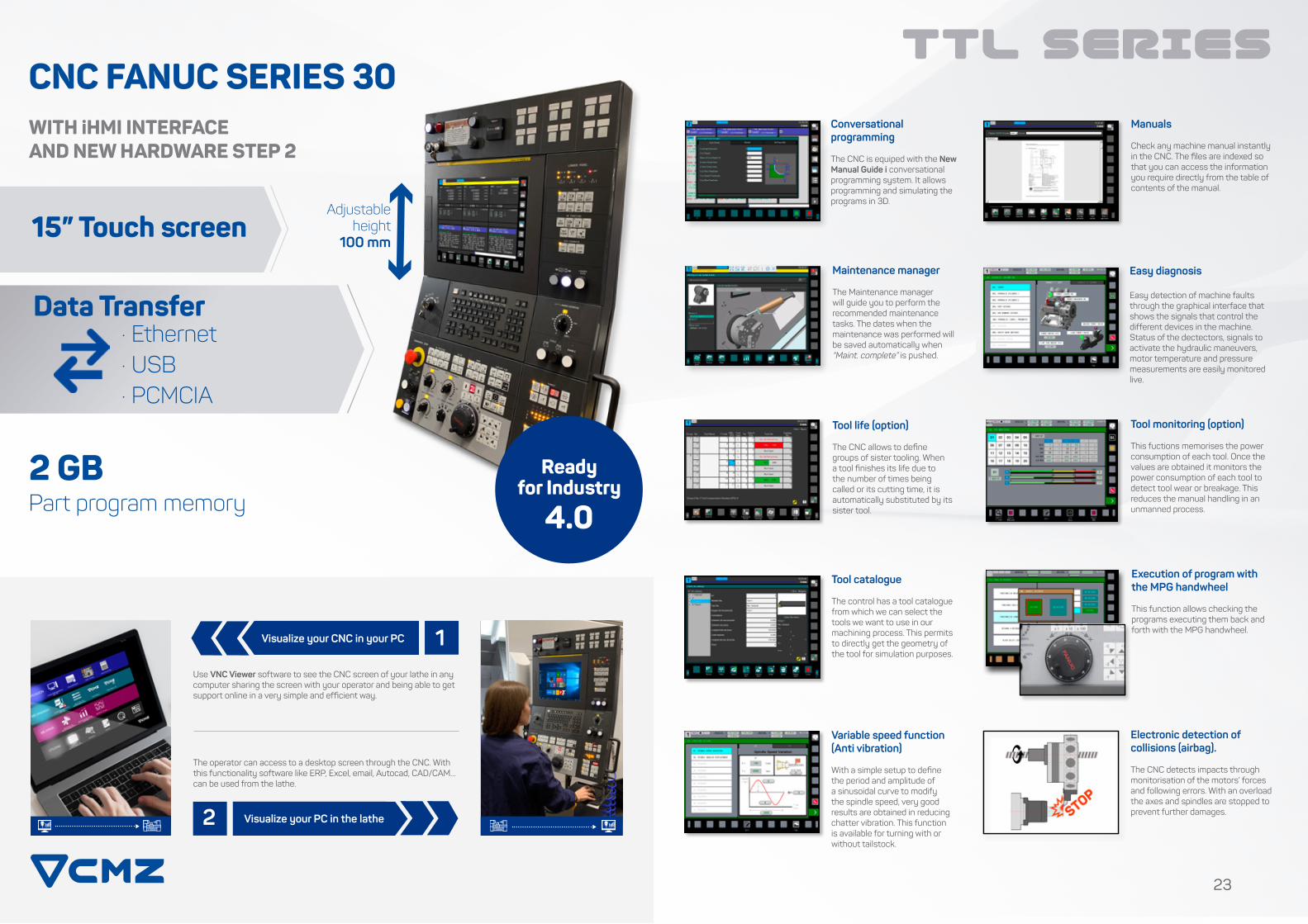
CNC FANUC SERIES 30 WITH iHMI INTERFACEAND NEW HARDWARE STEP 2
15” Touch screenMaintenance manager
The Maintenance manager will guide you to perform the recommended maintenance tasks. The dates when the maintenance was performed will be saved automatically when “Maint. complete” is pushed.
Manuals
Check any machine manual instantly in the CNC. The files are indexed so that you can access the information you require directly from the table of contents of the manual.
Tool life (option)
The CNC allows to define groups of sister tooling. When a tool finishes its life due to the number of times being called or its cutting time, it is automatically substituted by its sister tool.
Electronic detection of collisions (airbag).
The CNC detects impacts through monitorisation of the motors’ forces and following errors. With an overload the axes and spindles are stopped to prevent further damages.
Conversational programming
The CNC is equiped with the New Manual Guide i conversational programming system. It allows programming and simulating the programs in 3D.
TTL SERIES
Easy diagnosis
Easy detection of machine faults through the graphical interface that shows the signals that control the different devices in the machine. Status of the dectectors, signals to activate the hydraulic maneuvers, motor temperature and pressure measurements are easily monitored live.
23
· Ethernet· USB· PCMCIA
2 GBPart program memory
Data Transfer
Ready for Industry
4.0
Tool catalogue
The control has a tool catalogue from which we can select the tools we want to use in our machining process. This permits to directly get the geometry of the tool for simulation purposes.
Variable speed function (Anti vibration)
With a simple setup to define the period and amplitude of a sinusoidal curve to modify the spindle speed, very good results are obtained in reducing chatter vibration. This function is available for turning with or without tailstock.
Execution of program with the MPG handwheel
This function allows checking the programs executing them back and forth with the MPG handwheel.
Tool monitoring (option)
This fuctions memorises the power consumption of each tool. Once the values are obtained it monitors the power consumption of each tool to detect tool wear or breakage. This reduces the manual handling in an unmanned process.
Adjustable height
100 mm
The operator can access to a desktop screen through the CNC. With this functionality software like ERP, Excel, email, Autocad, CAD/CAM… can be used from the lathe.
Use VNC Viewer software to see the CNC screen of your lathe in any computer sharing the screen with your operator and being able to get support online in a very simple and efficient way.
Visualize your CNC in your PC 1
Visualize your PC in the lathe2
TTL SERIEs
25
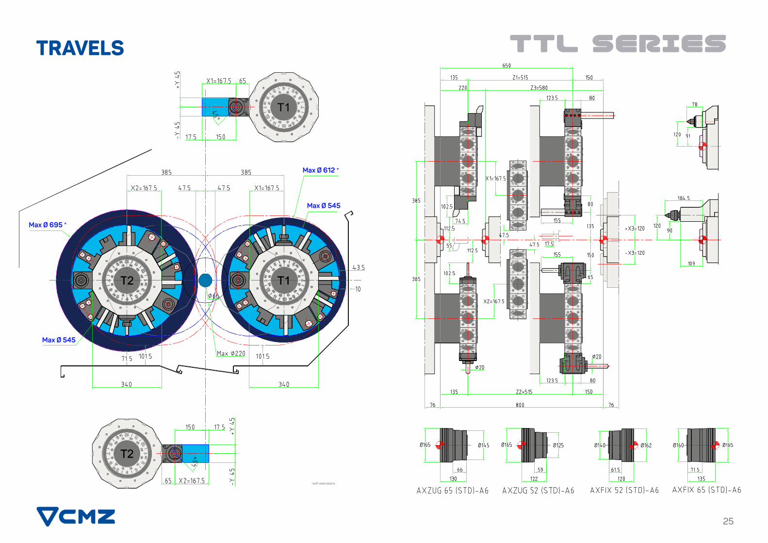
TRAVELS
Max Ø 695 *
Max Ø 545
Max Ø 545
Max Ø 612 *
*with restrictions.
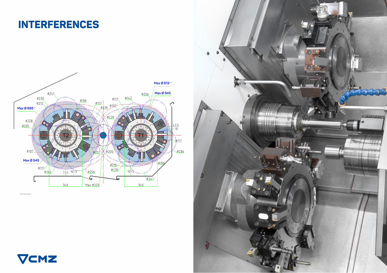
INTERFERENCES
Max Ø 695 *
Max Ø 545
Max Ø 545
Max Ø 612 *
*with restrictions.

TECHNICAL SPECIFICATIONS
TECHNICAL DATA
Maximum diameter of swinging allowed (mm)
Maximum turning diameter (mm)
Distance between spindle nose and tailstock centre (mm)
Distance between centres (mm)
X1_X2-axis travel (mm)
X3-axis travel (mm)
Z1_Z2-axis travel (mm)
Z3-axis travel (mm)
Y-axis travel (mm)
Fast feedrate X (m/min)
Fast feedrate Z (m/min)
Fast feedrate Y (m/min)
Axis acceleration
Maximum speed (rpm)
Bearing outside diameter (mm)
Bearing inside diameter (mm)
Spindle nose
Spindle inside diameter (mm)
Drawtube bore (mm)
Chuck diameter (mm)
Maximum bar diameter (mm)
Spindle power (kW) (max./S2 25%/ S1)
Turning torque (Nm) (max./S3 25%/ S1)
Morse taper
Tailstock travel (mm)
Max. force (kgf)
Number of positions (Number of index positions)
Section of tools (mm)
Changing time (S)
Interlocking force at 45 bar (kgf)
Number of driven tools
Turning speed (rpm)
Power (kW) (max./S1)
Maximum torque (Nm) (max./S1)
Maximum speed (rpm)
Bearing outside diameter (mm)
Bearing inside diameter (mm)
Spindle nose
Spindle inside diameter (mm)
Drawtube bore (mm)
Chuck diameter (mm)
Chuck bore (mm)
Power (kW) (max./ S3 25%/ S1))
Turning torque (Nm) (max./S3 25%/ S1)
Coolant tank (litres)
Hydraulic oil tank (litres)
Lubrication oil tank (litres)
Installed power (kVA)
Functioning voltage
Maximum environmental temperature (ºC)
Total weight (kg)
Dimensions
Internal volume (m3)
Side
Rear
GEN
ERA
L D
ATA
TAIL
STO
CK
SU
BS
PIN
DLE
MIS
CEL
AN
EOU
SD
RIV
EN
TOO
LSS
PIN
DLE
TUR
RET
12
12000
14 / 10
42 / 32
-
-
-
-
TTL-52-52
T1-T
2
T1-T
2
T1-T
2
T1-T
2
T1M
-T2
M
T1M
-T2
M
T1M
-T2
M
T1M
-T2
M
T1Y-
T2Y
T1Y-
T2Y
T1Y-
T2Y
T1Y-
T2Y
240
220
614
800
167,5
+120
-120
515
580
30
30
20
1g=9,8 m/s2
4500
150
100
ASA 6” A2
61
52
175 / 210
56 / 52
35,5 / 28,3 / 23,5
205 / 180 / 150
CM3
580
500
12 (24)
20x20 / 25x25
0,1 7
3200
4500
150
100
ASA 6” A2
61
52
175 / 210
56 / 52
35,5 / 28,3 / 23,5
205 / 180 / 150
510
330
10
4
87 87 87
400 V 50 Hz ±5%
[230 V 50 Hz ±5%]
35 º
11000
2860x2377x2289
1,7
+45
-45_
12
12000
14 / 10
42 / 32
-
-
-
-
TTL-52-66
240
220
614
800
167,5
+120
-120
515
580
30
30
20
1g=9,8 m/s2
4500
150
100
ASA 6” A2
61
52
175 / 210
56 / 52
35,5 / 28,3 / 23,5
205 / 180 / 150
CM3
580
500
12 (24)
20x20 / 25x25
0,1 7
3200
4000
170
110
ASA 6” A2
72,5
66
210
66
35,5 / 28,3 / 23,5
205 / 180 / 150
510
330
10
4
87 87 87
400 V 50 Hz ±5%
[230 V 50 Hz ±5%]
35 º
11000
2860x2377x2289
1,7
+45
-45_
12
12000
14 / 10
42 / 32
-
-
-
-
TTL-66-52
240
220
614
800
167,5
+120
-120
515
580
30
30
20
1g=9,8 m/s2
4000
170
110
ASA 6” A2
72,5
66
210
66
35,5 / 28,3 / 23,5
205 / 180 / 150
CM3
580
500
12 (24)
20x20 / 25x25
0,1 7
3200
4500
150
100
ASA 6” A2
61
52
175 / 210
56 / 52
35,5 / 28,3 / 23,5
205 / 180 / 150
510
330
10
4
87 87 87
400 V 50 Hz ±5%
[230 V 50 Hz ±5%]
35 º
11000
2860x2377x2289
1,7
+45
-45_
12
12000
14 / 10
42 / 32
-
-
-
-
TTL-66-66
240
220
614
800
167,5
+120
-120
515
580
30
30
20
1g=9,8 m/s2
4000
170
110
ASA 6” A2
72,5
66
210
66
35,5 / 28,3 / 23,5
205 / 180 / 150
CM3
580
500
12 (24)
20x20 / 25x25
0,17
3200
4000
170
110
ASA 6” A2
72,5
66
210
66
35,5 / 28,3 / 23,5
205 / 180 / 150
510
330
10
4
87 87 87
400 V 50 Hz ±5%
[230 V 50 Hz ±5%]
35 º
11000
2860x2377x2289
1,7
+45
-45_
DIMENSIONS
Side Exit Chip Conveyor
Rear Exit Chip Conveyor
1
2
(*) Approximate weights. Due to constant development of our products all specifications given here in are subject to change without notice.
31
CMZ Deutschland GmbHHolderäckerstr. 31
70499 Stuttgart (Germany)Tel. +49 (0) 711 469204 60
CMZ France SASParc Technologique Nord
65, Rue Condorcet38090 Vaulx Milieu (France)
Tel. +33 (0) 4 74 99 03 [email protected]
www.cmz.com
CMZ Italia S.r.l.Via Arturo Toscanini 6
20020 Magnago (Mi) ItalyTel. +39 (0) 331 30 87 00
CMZ Machinery Group S.A.Azkorra s/n.
48250 Zaldibar (Spain)Tel. +34 94 682 65 80
CMZ UK Ltd.6 Davy CourtCentral Park
RugbyCV23 0UZ (United Kingdom)
Tel. +44 (0) 1788 56 21 [email protected]
www.cmz.com
CMZ Machine Tool Manufacturer, S.L.Azkorra, s/n.
48250 Zaldibar (Spain)Tel. +34 946 826 580
Distributor:
Cat
alog
ue T
TL S
ERIE
S_E
N_v
1