tspwg m 3-250-04.97-05 proportioning concrete mixtures ... · document: tspwg m 3-250-04,...
TRANSCRIPT

TSPWG M 3-250-04.97-05 12 August 2019
TRI-SERVICE PAVEMENTS WORKING
GROUP (TSPWG) MANUAL
APPROVED FOR PUBLIC RELEASE; DISTRIBUTION UNLIMITED
PROPORTIONING CONCRETE
MIXTURES WITH GRADED AGGREGATES FOR
RIGID AIRFIELD PAVEMENTS

TSPWG M 3-250-04.97-05 12 August 2019
TRI-SERVICE PAVEMENTS WORKING GROUP (TSPWG) MANUAL
PROPORTIONING CONCRETE MIXTURES WITH GRADED AGGREGATES FOR RIGID AIRFIELD PAVEMENTS
Any copyrighted material included in this TSPWG Manual is identified at its point of use. Use of the copyrighted material apart from this TSPWG Manual must have the permission of the copyright holder. U.S. ARMY CORPS OF ENGINEERS
NAVAL FACILITIES ENGINEERING COMMAND
AIR FORCE CIVIL ENGINEER CENTER (Preparing Activity) Record of Changes (changes are indicated by \1\ ... /1/)
Change No. Date Location
This TSPWG Manual supersedes Air Force ETL97-5, Proportioning Concrete Mixtures with Graded Aggregates for Rigid Airfield Pavements, dated April 1997.

TSPWG M 3-250-04.97-05 12 August 2019
FOREWORD
This Tri-Service Pavements Working Group Manual supplements guidance found in other Unified Facilities Criteria, Unified Facility Guide Specifications, Defense Logistics Agency specifications, and Service-specific publications. All construction outside of the United States is also governed by Status of Forces Agreements (SOFA), Host Nation Funded Construction Agreements (HNFA), and in some instances, Bilateral Infrastructure Agreements (BIA.) Therefore, the acquisition team must ensure compliance with the most stringent of the TSPWG Manual, the SOFA, the HNFA, and the BIA, as applicable. This manual provides guidance for selecting aggregate grading for use in concrete mixtures to construct military rigid airfield pavements. The information in this TSPWG Manual is referenced in technical publications found on the Whole Building Design Guide. It is not intended to take the place of Service-specific doctrine, Technical Orders (TOs), field manuals, technical manuals, handbooks, Tactics, Techniques, and Procedures (TTPs), or contract specifications, but should be used along with these to help ensure pavements meet mission requirements. TSPWG Manuals are living documents and will be periodically reviewed, updated, and made available to users as part of the Services’ responsibility for providing technical criteria for military construction, maintenance, repair, or operations. Headquarters, U.S. Army Corps of Engineers (HQUSACE), Naval Facilities Engineering Command (NAVFAC), and Air Force Civil Engineer Center (AFCEC) are responsible for administration of this manual. Technical content of this TSPWG Manual is the responsibility of the Tri-Service Pavements Working Group (TSPWG). Defense agencies should contact the preparing activity for document interpretation. Send recommended changes with supporting rationale to the respective service TSPWG member. TSPWG Manuals are effective upon issuance and are distributed only in electronic media from the following source:
• Whole Building Design Guide web site http://dod.wbdg.org/. Hard copies of TSPWG Manuals printed from electronic media should be checked against the current electronic version prior to use to ensure that they are current.

TSPWG M 3-250-04.97-05 12 August 2019
TRI-SERVICE PAVEMENTS WORKING GROUP MANUAL (TSPWG M) NEW SUMMARY SHEET
Document: TSPWG M 3-250-04, Proportioning Concrete Mixtures with Graded Aggregates for Rigid Airfield Pavements Superseding: Engineering Technical Letter (ETL) 97-5, Proportioning Concrete Mixtures with Graded Aggregates for Rigid Airfield Pavements
Description: This TSPWG Manual provides guidance for selecting aggregate grading for use in concrete mixtures to construct military rigid airfield pavements.
Reasons for Document: Provide designers and maintenance personnel the latest guidance.
Impact: There is no cost impact. The following benefits should be realized:
• Supplemental information on selection of aggregate grading for use in concrete mixtures will be available to all Services.
• Updates of this supplemental information will include inputs from all Services.
Unification Issues None.

TSPWG M 3-250-04.97-05 12 August 2019
i
TABLE OF CONTENTS
CHAPTER 1 INTRODUCTION ....................................................................................... 1
1-1 PURPOSE. ................................................................................................ 1
1-2 BACKGROUND. ....................................................................................... 1
1-3 SCOPE. ..................................................................................................... 2
CHAPTER 2 MATERIALS .............................................................................................. 3
2-1 INTRODUCTION. ...................................................................................... 3
2-2 COARSE AGGREGATE. .......................................................................... 3
2-2.1 Composition. .............................................................................................. 3
2-2.2 Quality. ....................................................................................................... 3
2-2.3 Particle Shape. .......................................................................................... 3
2-2.4 Maximum Size. .......................................................................................... 3
2-2.5 Grading. ..................................................................................................... 4
2-3 BLENDING AGGREGATE. ....................................................................... 4
2-3.1 Composition. .............................................................................................. 4
2-3.2 Quality. ....................................................................................................... 4
2-3.3 Particle Shape. .......................................................................................... 4
2-4 FINE AGGREGATE................................................................................... 4
2-4.1 Composition. .............................................................................................. 4
2-4.2 Quality. ....................................................................................................... 4
2-4.3 Grading. ..................................................................................................... 4
2-5 CEMENT. ................................................................................................... 5
2-5.1 Specifications. ............................................................................................ 5
2-5.2 Sources. ..................................................................................................... 5
2-5.3 Content. ..................................................................................................... 5
2-6 WATER. ..................................................................................................... 5
2-7 MINERAL ADMIXTURES (FLY ASH). ...................................................... 6
2-8 CHEMICAL ADMIXTURES. ...................................................................... 6
2-8.1 Air-entraining. ............................................................................................ 6
2-8.2 Set-retarding. ............................................................................................. 6
2-8.3 Set-accelerating. ........................................................................................ 7
2-8.4 Water-reducing. ......................................................................................... 7

TSPWG M 3-250-04.97-05 12 August 2019
ii
2-8.5 High-range Water-reducing. ....................................................................... 7
2-9 TARGET AIR CONTENT. .......................................................................... 7
CHAPTER 3 COMBINED AGGREGATE GRADING ...................................................... 9
3-1 INTRODUCTION. ...................................................................................... 9
3-2 PERCENT COMBINED AGGREGATE RETAINED. ................................. 9
3-3 COARSENESS FACTOR/WORKABILITY FACTOR. ............................... 9
3-4 AGGREGATE PROPORTIONING GUIDE. ............................................. 11
3-5 INTERPRETATION OF GRAPHICAL PROCEDURES. .......................... 12
3-5.1 Significance and Limits. ........................................................................... 12
3-5.2 Percent Combined Aggregate Retained. ................................................. 13
3-6 FINENESS MODULUS OF THE FINE AGGREGATE............................. 18
CHAPTER 4 MIX PROPORTIONING ........................................................................... 21
4-1 INTRODUCTION. .................................................................................... 21
4-2 ESTIMATION OF WORKABILITY........................................................... 21
4-3 NOMINAL MAXIMUM SIZE OF COARSE AGGREGATE. ..................... 21
4-4 ESTIMATION OF CEMENTITIOUS MATERIAL CONTENT. .................. 21
4-5 ESTIMATION OF AIR CONTENT. .......................................................... 22
4-6 COARSE AND FINE AGGREGATE AS SINGLE AGGREGATE BLEND. ................................................................................................................. 22
4-7 WEIGHTED AVERAGE SPECIFIC GRAVITY OF AGGREGATE BLEND. ................................................................................................................. 23
4-8 ESTIMATION OF WATER CEMENTITIOUS MATERIAL RATIO. .......... 23
4-9 FRESH CONCRETE UNIT MASS IN KILOGRAMS PER CUBIC METER. ................................................................................................................. 23
4-10 ESTIMATION OF COMBINED AGGREGATE QUANTITY. .................... 24
4-11 ADJUSTMENTS FOR AGGREGATE MOISTURE. ................................ 24
4-12 TRIAL BATCH ADJUSTMENTS. ............................................................ 24
4-13 FIELD TRIALS. ....................................................................................... 25
CHAPTER 5 SAMPLE COMPUTATIONS .................................................................... 27
5-1 EXAMPLE 1. ........................................................................................... 27
5-1.1 Description. .............................................................................................. 27
5-1.2 CALCULATIONS. .................................................................................... 29
5-2 EXAMPLE 2. ........................................................................................... 36
5-2.1 Description. .............................................................................................. 36

TSPWG M 3-250-04.97-05 12 August 2019
iii
5-2.2 Calculations. ............................................................................................ 38
APPENDIX A best practices ....................................................................................... 45
APPENDIX B GLOSSARY ........................................................................................... 47
B-1 ACRONYMS ............................................................................................ 47
APPENDIX C references ............................................................................................. 49
FIGURES
Figure 3-1 Percent Combined Aggregate Retained .............................................. 9
Figure 3-2 Aggregate Proportioning Guide ......................................................... 10
Figure 3-3 Workability Box Within Aggregate Proportioning Guide ................. 11
Figure 3-4 Daily Variance Within Workability Box for Aggregate Proportioning ...................................................................................... 12
Figure 3-5 “Haystack” Particle Distribution for a Uniformly Graded Mixture .. 13
Figure 3-6 Example A ............................................................................................ 14
Figure 3-7 Example B ............................................................................................ 15
Figure 3-8 Example C ............................................................................................ 16
Figure 3-9 0.45 Power Grading Chart .................................................................. 17
Figure 3-10 Example C Plotted on 0.45 Power ...................................................... 17
Figure 3-11 Fine Aggregate Grading Limits .......................................................... 18
Figure 5-1 Grading of 37.5mm Nominal Coarse Aggregate and ASTM C33/C33M Grading Limits ................................................................... 28
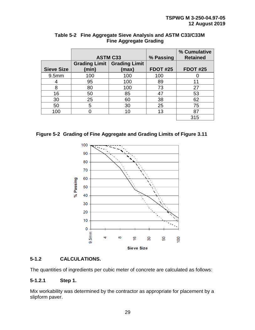
Figure 5-2 Grading of Fine Aggregate and Grading Limits of Figure 3.11 ....... 29
Figure 5-3 Aggregate Proportioning Guide for Combined Aggregate .............. 32
Figure 5-4 Percent Combined Aggregate Retained ............................................ 32
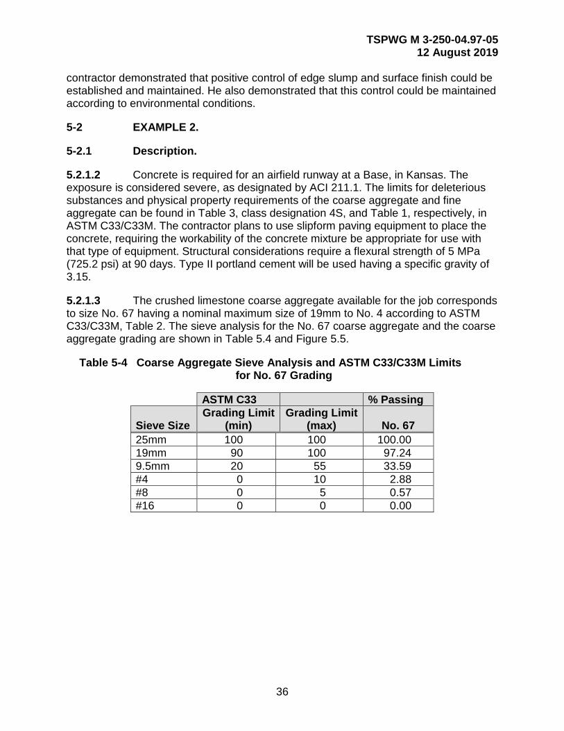
Figure 5-5 Grading of 19mm Nominal Coarse Aggregate and ASTM C33/C33M Grading Limits ..................................................................................... 37
Figure 5-6 Grading of Fine Aggregate and Grading Limits of Figure 3.11 ....... 38
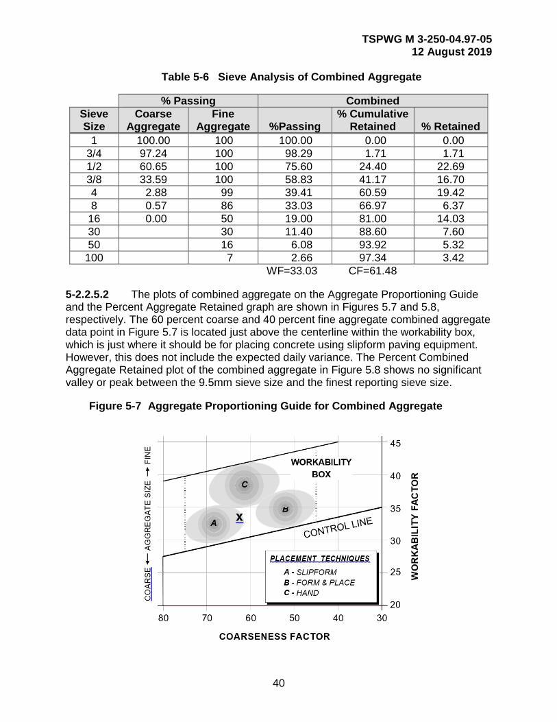
Figure 5-7 Aggregate Proportioning Guide for Combined Aggregate .............. 40
Figure 5-8 Percent Combined Aggregate Retained ............. Error! Bookmark not defined.

TSPWG M 3-250-04.97-05 12 August 2019
iv
TABLES
Table 2-1 Target Air Content for Airfield Pavement Concrete ........................... 8
Table 3-1 Fineness Modulus Calculation ........................................................... 19
Table 4-1 Target Air Content for Airfield Pavement Concrete ......................... 22
Table 5-1 Coarse Aggregate Sieve Analysis and ASTM C33/C33M Limits for No. 467 Grading .............................................................................. 27
Table 5-2 Fine Aggregate Sieve Analysis and ASTM C33/C33M Fine Aggregate Grading.............................................................................. 29
Table 5-3 Sieve Analysis of Combined Aggregate ........................................... 31
Table 5-4 Coarse Aggregate Sieve Analysis and ASTM C33/C33M Limits for No. 67 Grading ............................................................................... 36
Table 5-5 Fine Aggregate Sieve Analysis and ASTM C33/C33M Fine Aggregate Grading.............................................................................. 38
Table 5-6 Sieve Analysis of Combined Aggregate ........................................... 40

TSPWG M 3-250-04.97-05 12 August 2019
1
CHAPTER 1 INTRODUCTION
1-1 PURPOSE.
This TSPWG M provides a method for selecting aggregate grading for concrete mixtures to be used in military rigid airfield pavement surface courses. Selected gradings are compatible with workability requirements of concrete placements by mechanical means, either slipform, form and place, or manual. Concrete durability is attained when guidance in this TPSWG M is used to develop proportions for concrete mixtures.
1-2 BACKGROUND.
Military rigid pavements are approaching the end of their calculated life span. Most date to the late 1950’s and early 1960’s, and are being upgraded or replaced because they can no longer be effectively maintained. Reconstruction and rehabilitation started in the late 1980’s. A significant number of these experience early age distress syndrome, some as early as one year post-reconstruction/rehabilitation. All of these failed pavements are structurally adequate and meet applicable specifications, but suffer surface deterioration, risking damage to high value aircraft.
Early distress syndrome presents itself in two ways: (1) spalling of the joint seal reservoir; or (2) surface delamination or raveling. Surface distress usually occurs within one year of construction. It occurs in all environments, on projects accomplished by different contractors using different material sources and by different construction agents. Problems are typically attributed to poor mixture design, poor workmanship, poor quality control, or inadequate construction inspection.
1-2.1 The United States Army Corps of Engineers, Engineering Research and Development Center, (USACE/ERDC investigation concluded that “the primary cause of the early-age spalling that recently has become relatively prevalent at military airfields appears to be primarily due to poor construction practices that may be caused or at least exacerbated by poor concrete mixture proportioning.”1 The Army Corps of Engineers further concluded that, “the engineering and construction profession should develop improved guidance on proportioning concrete mixtures for paving that must address workability of the mixture for slipformed paving and control of edge slump.”
1-2.2 The Air Force Civil Engineering Center, Operations Directorate (AFCEC/CO), evaluated numerous projects completed since 1987, including both pavements that have and pavements that have not exhibited early distress syndrome. A common factor was the combined grading of the aggregates and the high variability of aggregate gradations within specification-imposed limits. Generally, projects constructed with aggregates near to being well-graded performed better than those constructed with gap-graded or poorly-graded aggregates. The constructibility and
1 Rollings, Raymond, S., “Joint Spalling in Newly Constructed Concrete Pavements,” ASCE Journal of Performance of Constructed Facilities, 1996.

TSPWG M 3-250-04.97-05 12 August 2019
2
uniformity of concrete mixtures with well-graded aggregate contributed to better pavement performance.
1-2.3 American Concrete Institute (ACI) 211.1, Standard Practice for Selecting Proportions for Normal, Heavyweight, and Mass Concrete, is the accepted standard for concrete mixture proportioning by both industry and the Department of Defense (DoD). However, this standard can produce concrete mixtures with poorly graded aggregate, containing fewer coarse aggregates and more fine aggregate. Footnote recommendations in ACI 211.1 for pavement-quality concrete are generalized, and mostly ignored. Mixtures proportioned using ACI 211.1 tend to be gap-graded, with high sand content, and prone to segregation when subject to vibration. This results in pavement placements with edge slump, consolidation, and finishing problems -- though it is possible to place and finish a pavement with gap-graded aggregates.
1-3 SCOPE.
1-3.1 This TSPWG M must be used with DoD Guide Specification 32 13 14.13, Concrete Paving for Airfields and Other Heavy Duty Pavements.
1-3.2 Procure materials using American Society for Testing and Materials (ASTM) references, local Department of Transportation (DOT) references, or other identification. Use locally available materials. Ensure the person purchasing raw materials establishes the limits of the grading selected for each material to be used in a certain combined grading; i.e., stockpile control. When purchasing an aggregate component, specify not only the standard stone size, but also the gradation and tolerance for variance within that generic size limit. Quality control procedures assure that the combined grading remains within the range selected for mixture proportioning.
1-3.3 Each aggregate (coarse, blend, or fine) contributes to the workability, uniformity, and suitability of the concrete mixture. Size is only one indicator of expected performance. Shape, texture, and angularity is also considered in proportioning a mixture that responds positively to a given method of placement and finishing. Establish a catalog of aggregate performance and combined gradings that resulted in successful pavement placement as a reference for future construction activities.
1-3.4 There are no cookbook solutions to a concrete mixture proportioning study. Not all proposed mixtures meet all requirements. Obtain the best possible product given the resource limitations of the project. Aggregate blending may be necessary using materials which, individually, would not satisfy the grading limits of standard references. Do not sacrifice aggregate quality to attain appropriate grading, or to be able to use local materials.
TSPWG M 3-250-04.97-05 12 August 2019
3
CHAPTER 2 MATERIALS
2-1 INTRODUCTION.
Materials used for the concrete mixture include: coarse aggregate, blended aggregate, fine aggregate, cement, water, mineral admixtures, chemical admixtures, and air content.
2-2 COARSE AGGREGATE.
2-2.1 Composition.
Coarse aggregate consists of one or a combination of gravel or crushed aggregate with particles being retained on and above the No. 4 ASTM standard sieve.
2-2.2 Quality.
Ensure aggregates meet the quality requirements of the specification. Designate the class of coarse aggregate to be used in the project based on factors of exposure. Class designations include: mild exposure, where concrete is rarely exposed to freezing in the presence of moisture; moderate exposure, where concrete is not continually exposed to freezing and thawing in the presence of moisture or to deicing chemicals; and severe exposure, where concrete may become saturated with moisture prior to repeated freezing and thawing and be exposed to deicing chemicals or other aggressive agents. If not familiar with the geographical locations corresponding to the above exposure conditions, refer to ASTM C33/C33M, Standard Specification for Concrete Aggregates, Figure 1, “Location of Weathering Regions.”
2-2.3 Particle Shape.
Ensure the quantity of flat and elongated particles in any size group does not exceed 20 percent, by mass, as determined by ASTM D5821 Standard Test Method for Determining the Percentage of Fractured Particles in Coarse Aggregates. A flat particle is defined as one with a ratio of width to thickness greater than three. An elongated particle is one having a ratio of length to width greater than three. The water required to produce a given workability increases as the number of flat, elongated and rough textured particles increases.
2-2.4 Maximum Size.
The nominal maximum aggregate size is defined as the smallest sieve opening through which the entire amount of the aggregate is permitted to pass. The nominal maximum sieve sizes used for airfield pavements are 1.5 inches (37.5mm), 1.0 inches (25mm), and 0.75 inches (19mm). The nominal maximum aggregate size for pavements constructed in geographical locations where D-cracking aggregates are encountered is 0.75 inches (19mm).

TSPWG M 3-250-04.97-05 12 August 2019
4
2-2.5 Grading.
Aggregates are sampled according to ASTM D75/D75M, Standard Practice for Sampling Aggregates, prior to performing a sieve analysis according to ASTM C136, Standard Test Method for Sieve Analysis of Fine and Coarse Aggregates. Sieves used for the analysis include 2.0 inches (50mm), 1.5 inches (37.5mm), 1.0 inches (25mm), 0.75 inches (19mm), 0.5 inches (12.5mm), 0.375 inches (9.5mm), No. 4 (4.75mm), and No. 8.(2.36mm)
2-3 BLENDING AGGREGATE.
2-3.1 Composition.
Blending aggregates may be either natural deposits, manufactured products, or combinations thereof. Blending particle sizes are immediate, normally passing the 0.375 inch (9.5mm) sieve and retained on the No. 50 sieve (300um).
2-3.2 Quality.
Ensure blending particle sizes meet the quality fine aggregate requirements of ASTM C33/C33M, Standard Specification for Concrete Aggregates, or UFGS 32 13 14.13, whichever is more stringent.
2-3.3 Particle Shape.
Particles are generally cubical, without elongated or slivered materials.
2-4 FINE AGGREGATE.
2-4.1 Composition.
Fine aggregate is clean granular material, typically natural or manufactured sand or crushed stone, or a combination thereof, with most particles passing the No. 4 ASTM standard sieve.
2-4.2 Quality.
The quantity of undesirable substances in fine aggregate should not exceed limits of in ASTM C33/C33M, Table 1, or UFGS 32 13 14.13, whichever is more stringent
2-4.3 Grading.
Proportion fine aggregate, as delivered to the stockpile, in accordance with ASTM C33/C33M. The maximum limitation of ASTM C33/C33M for fineness modulus of 3.1 is NOT applicable for fine aggregate being used for slipform paving and form-in-place applications. The DoD limitation for fineness modulus is not less than 2.5 nor more than 3.40. An example of a fineness modulus calculation is provided in Table 3.1. No more than 45 percent of fine aggregate should pass any sieve and be retained on the next consecutive sieve. Sample fine aggregates according to ASTM D75 prior to performing

TSPWG M 3-250-04.97-05 12 August 2019
5
a sieve analysis according to ASTM C136. Sieves used for analysis include 9.5mm, No. 4, No. 8, No. 16, No. 30, No. 50, and No. 100.
2-5 CEMENT.
2-5.1 Specifications.
Ensure portland cement conforms to ASTM C150/C150M, Standard Specification for Portland Cement. The type of cement to be used is selected by the contractor. Limit tricalcium silicate content to a maximum of 55 percent and alkalies (calculated as Na2O + 0.6 K2O) to 0.75 percent, maximum.
Do not use Types IA, IIA, and IIIA, portland cements containing interground additions of air-entraining agent for airfield pavement mix designs. Consider blended cements consisting of two or more inorganic constituents that contribute to the strength-gaining properties of the cement that meet the performance requirements of ASTM C1157/C1157M on a case-by-case basis only.
2-5.2 Sources.
Since many foreign sources of cement satisfying ASTM C1157/C1157M are being used today for pavement projects, request the cement be sampled and tested to verify compliance according to ASTM C183/C183M, Standard Practice for Sampling and the Amount of Testing of Hydraulic Cement, and ASTM C1157/C1157M.
2-5.3 Content.
Minimum portland cement content should be 335 kilograms per cubic meter [(kg/m3) (564 lb/yd3)] of concrete when using only portland cement as the cementitious component of the concrete mixture. When pozzalanic materials such as fly ash are used in concrete, the minimum amount of portland cement should be 307 kg/m3 (517 lb/yd3) of concrete. The amount of cementitious material is determined by the amount of portland cement plus the amount of fly ash.
2-6 WATER.
Water for washing aggregates and for mixing concrete should be free from harmful amounts of oil, acid, salt, alkali, organic matter, or other harmful substances. The properties of the water should exceed the minimum requirements given in CRD-C 400, Requirements for Water for Use in Mixing or Curing Concrete.
The water/cementitious material ratio is defined as the mass of water (W) divided by the combined mass of cement (C), plus the mass of fly ash (P), as given in the following equation (W/C+P). This ratio should not exceed 0.45. The water/cementitious material ratio should represent the minimum amount of water required to obtain a given workability for any given aggregate grading.
TSPWG M 3-250-04.97-05 12 August 2019
6
2-7 MINERAL ADMIXTURES (FLY ASH).
Class F and Class C fly ashes, as defined by ASTM C618, Standard Specification for Coal Fly Ash and Raw or Calcined Natural Pozzolan for Use in Concrete, are commonly used as pozzolanic admixtures for concrete. The mass of fly ash used in the mix should not be less than 15 percent, nor more than 25 percent of the total cementitious material; i.e., the ratio of the mass of fly ash divided by the combined mass of fly ash and the mass of portland cement should not be less than 15 percent, nor more than 25 percent of the total cementitious material.
When using Class C fly ash, a chemical analysis should be conducted to evaluate the solubility parameters of the aluminum (Al2O3) and the sulfur (SO3). One recommenda-tion is “solubility of the SO3 and Al2O3 should be a minimum of 90 percent of the total available.”2
2-8 CHEMICAL ADMIXTURES.
Chemical admixtures are ingredients in concrete other than portland cement, mineral admixtures, water, or aggregates, that are included in the mixture prior to placement. Chemical admixtures are classified as: air-entraining, set-retarding, set-accelerating, water reducing, and high-range water-reducing. Specifications for chemical admixtures are given in ASTM C494/C494M, Standard Specification for Chemical Admixtures for Concrete.
Admixtures used in the mix design of rigid airfield pavements must be compatible with other mixture components and certified as being so by the manufacturer and/or its representative for a given concrete mixture, and can in no way impair the quality of the mixture by affecting the workability, placeability, finishibility, and strength.
2-8.1 Air-entraining.
Air-entraining admixtures are used to purposely entrain microscopic air bubbles into concrete. Air entrainment should improve the durability of the concrete exposed to cycles of freezing and thawing. The type of admixture and dosage rate should have an effect on workability and strength. Air entrainment should be used in both severe and moderate weathering regions as described in ASTM C33/C33M.
2-8.2 Set-retarding.
Set-retarding admixtures retard the time of setting of concrete. These admixtures are used during hot weather concreting; e.g., when fresh concrete temperatures exceed 29 °C or when concrete is being delivered from a considerable distance.
2Gress, D.L., “Recommendations for Mitigating Early Distress in Concrete Pavements,” Presented to the American Concrete Pavement Association, Durability Committee, June 12, 1996.
TSPWG M 3-250-04.97-05 12 August 2019
7
2-8.3 Set-accelerating.
Set-accelerating admixtures are used to accelerate the strength development of concrete at an early age. Calcium chloride is not recommended by DoD as an accelerator for rigid airfield pavements. Only non-chloride set-accelerating admixtures meeting ASTM C494/C494M should be used.
2-8.4 Water-reducing.
Water-reducing admixtures are used to reduce the quantity of mixing water required to produce concrete of a certain workability. Reducing the water cement ratio increases the strength of the concrete without reducing the workability; or, the workability of the concrete mixture can be increased without increasing the water/cement ratio, thereby maintaining the strength of the mix. Ordinary water reducers reduce the water content by approximately 5 to 10 percent.
2-8.5 High-range Water-reducing.
High-range water-reducing admixtures are described in ASTM C1017/C1017M, Standard Specification for Chemical Admixtures for Use in Producing Flowing Concrete, and C494/C494M Types F and G specifications. High-range water-reducers reduce water content by 12 to 30 percent. High-range water reducers are more effective in reducing the water/cement ratio for a given concrete. Yet, the effect is usually short-lived, and loss of workability often occurs within 30 to 60 minutes. Compatibility with other admixtures, particularly air-entraining agents, must be verified, since high-range water-reducing admixtures can significantly affect the amount and size of entrained air bubbles.
2-9 TARGET AIR CONTENT.
The air content, by volume, should be selected based upon Table 2.1. The air content should be determined from concrete samples selected from in front of the paver. Loss of air due to mixing, transportation, and placement must be allowed for. The exposure definitions provided in Portland Cement Association (PCA) Engineering Bulletin (EB) 001, Design and Control of Concrete Mixtures, apply.

TSPWG M 3-250-04.97-05 12 August 2019
8
Table 2-1 Target Air Content for Airfield Pavement Concrete
TARGET AIR CONTENT (PERCENT BY VOLUME)
Nominal Maximum Aggregate Size (mm) Severe Exposure Moderate Exposure Mild Exposure
37.5 5.5 4.5 2.5 25 6 4.5 3 19 6 5 3.5
Note: Air content of delivered concrete must be within -1 to +2 percentage points of the table target values.3
3 Design and Control of Concrete Mixtures, Engineering Bulletin EB001, Portland Cement Association.

TSPWG M 3-250-04.97-05 12 August 2019
9
CHAPTER 3 COMBINED AGGREGATE GRADING
3-1 INTRODUCTION.
The concrete mixture should be proportioned so that the requirements for workability and finishibility are satisfied. The mixture should also be proportioned as a well-graded combined aggregate, and the minimum requirements for air content and water cementitious ratio are not exceeded.
3-2 PERCENT COMBINED AGGREGATE RETAINED.
Grading reports should include the following sieve sizes: sieves used for the analysis include 50mm, 37.5mm, 25mm, 19mm, 12.5mm, 9.5mm, No. 4, No. 8, No. 16, No. 30, No. 50, and No. 100. The proportions selected for the combined gradation should be plotted on a graph as the percentage retained for each reporting sieve size (y-axis) versus the considered sieve size (x-axis). The plot of the graph should be a line showing a relatively smooth transition between coarse and fine aggregate. The maximum and minimum percent retained limits, represented by the dotted lines in Figure 3.1, are to be taken only as a guide, and the plot should not have a significant valley or peak between the 9.5mm sieve size and the finest reporting sieve size. An example of the percent aggregate retained graph, including a satisfactory and unsatisfactory combined aggregate gradation plot, is shown in Figure 3.1.
Figure 3-1 Percent Combined Aggregate Retained
3-3 COARSENESS FACTOR/WORKABILITY FACTOR.
3-3.1 The combined aggregate grading should be used to calculate a coarseness factor and a workability factor. The coarseness factor for a particular combined aggregate
TSPWG M 3-250-04.97-05 12 August 2019
10
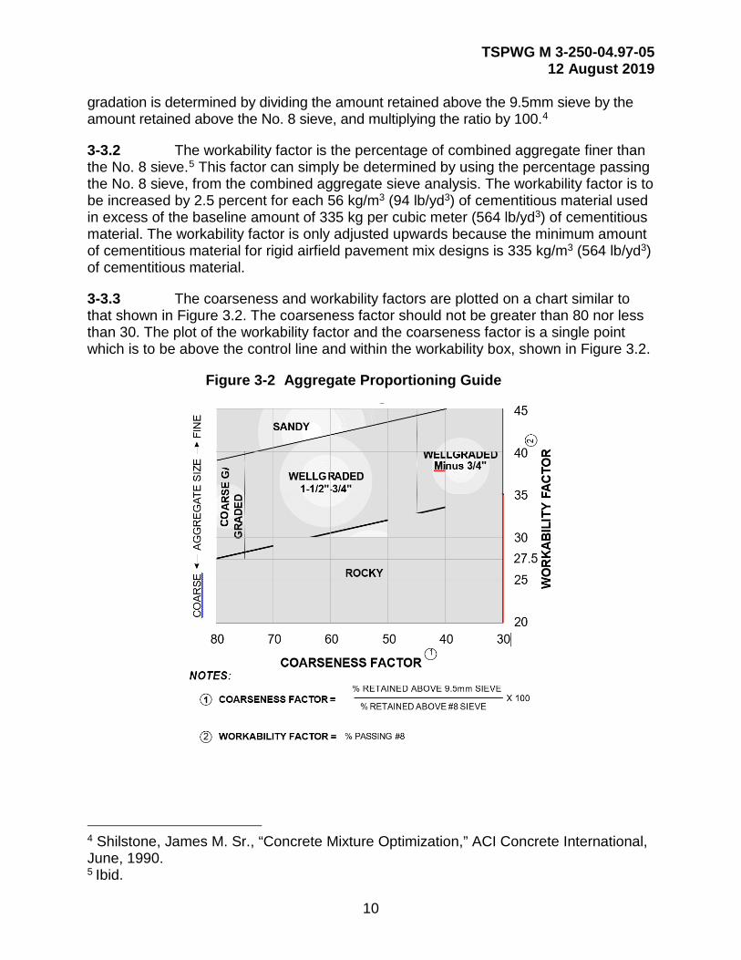
gradation is determined by dividing the amount retained above the 9.5mm sieve by the amount retained above the No. 8 sieve, and multiplying the ratio by 100.4
3-3.2 The workability factor is the percentage of combined aggregate finer than the No. 8 sieve.5 This factor can simply be determined by using the percentage passing the No. 8 sieve, from the combined aggregate sieve analysis. The workability factor is to be increased by 2.5 percent for each 56 kg/m3 (94 lb/yd3) of cementitious material used in excess of the baseline amount of 335 kg per cubic meter (564 lb/yd3) of cementitious material. The workability factor is only adjusted upwards because the minimum amount of cementitious material for rigid airfield pavement mix designs is 335 kg/m3 (564 lb/yd3) of cementitious material.
3-3.3 The coarseness and workability factors are plotted on a chart similar to that shown in Figure 3.2. The coarseness factor should not be greater than 80 nor less than 30. The plot of the workability factor and the coarseness factor is a single point which is to be above the control line and within the workability box, shown in Figure 3.2.
Figure 3-2 Aggregate Proportioning Guide
4 Shilstone, James M. Sr., “Concrete Mixture Optimization,” ACI Concrete International, June, 1990. 5 Ibid.
TSPWG M 3-250-04.97-05 12 August 2019
11
3-4 AGGREGATE PROPORTIONING GUIDE.
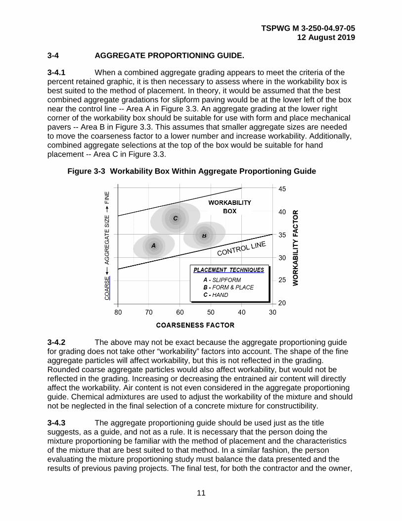
3-4.1 When a combined aggregate grading appears to meet the criteria of the percent retained graphic, it is then necessary to assess where in the workability box is best suited to the method of placement. In theory, it would be assumed that the best combined aggregate gradations for slipform paving would be at the lower left of the box near the control line -- Area A in Figure 3.3. An aggregate grading at the lower right corner of the workability box should be suitable for use with form and place mechanical pavers -- Area B in Figure 3.3. This assumes that smaller aggregate sizes are needed to move the coarseness factor to a lower number and increase workability. Additionally, combined aggregate selections at the top of the box would be suitable for hand placement -- Area C in Figure 3.3.
Figure 3-3 Workability Box Within Aggregate Proportioning Guide
3-4.2 The above may not be exact because the aggregate proportioning guide for grading does not take other “workability” factors into account. The shape of the fine aggregate particles will affect workability, but this is not reflected in the grading. Rounded coarse aggregate particles would also affect workability, but would not be reflected in the grading. Increasing or decreasing the entrained air content will directly affect the workability. Air content is not even considered in the aggregate proportioning guide. Chemical admixtures are used to adjust the workability of the mixture and should not be neglected in the final selection of a concrete mixture for constructibility.
3-4.3 The aggregate proportioning guide should be used just as the title suggests, as a guide, and not as a rule. It is necessary that the person doing the mixture proportioning be familiar with the method of placement and the characteristics of the mixture that are best suited to that method. In a similar fashion, the person evaluating the mixture proportioning study must balance the data presented and the results of previous paving projects. The final test, for both the contractor and the owner,
TSPWG M 3-250-04.97-05 12 August 2019
12
are the characteristics and the response of the mixture to the method of placement as observed at a test strip placement.
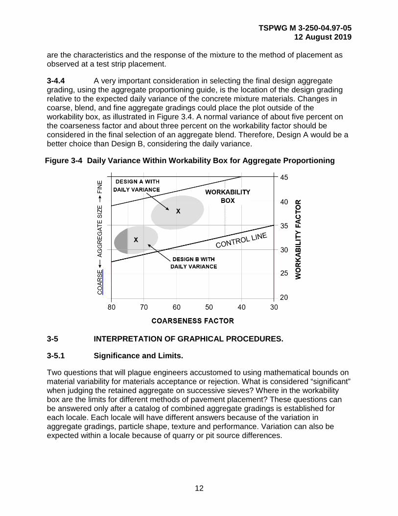
3-4.4 A very important consideration in selecting the final design aggregate grading, using the aggregate proportioning guide, is the location of the design grading relative to the expected daily variance of the concrete mixture materials. Changes in coarse, blend, and fine aggregate gradings could place the plot outside of the workability box, as illustrated in Figure 3.4. A normal variance of about five percent on the coarseness factor and about three percent on the workability factor should be considered in the final selection of an aggregate blend. Therefore, Design A would be a better choice than Design B, considering the daily variance.
Figure 3-4 Daily Variance Within Workability Box for Aggregate Proportioning
3-5 INTERPRETATION OF GRAPHICAL PROCEDURES.
3-5.1 Significance and Limits.
Two questions that will plague engineers accustomed to using mathematical bounds on material variability for materials acceptance or rejection. What is considered “significant” when judging the retained aggregate on successive sieves? Where in the workability box are the limits for different methods of pavement placement? These questions can be answered only after a catalog of combined aggregate gradings is established for each locale. Each locale will have different answers because of the variation in aggregate gradings, particle shape, texture and performance. Variation can also be expected within a locale because of quarry or pit source differences.

TSPWG M 3-250-04.97-05 12 August 2019
13
3-5.2 Percent Combined Aggregate Retained.
3-5.2.1 A generic judgment can be made about the expected performance of concrete pavements based upon known material characterizations. The first involves selecting aggregate grading based upon retainage, by mass, on successive sieve sizes.
3-5.2.2 The optimum solution to the well graded aggregate criteria is nominally the classical “haystack,” Figure 3.5. The “haystack” grading is recommended by the American Concrete Pavement Association (ACPA)6 for fast track paving because it provides for reduced water demand, increased durability, and better workability. The classic “haystack” is almost impossible to produce from most local materials at any economic advantage. The question then becomes how close you must be to the “haystack” grading configuration.
Figure 3-5 “Haystack” Particle Distribution for a Uniformly Graded Mixture
3-5.2.3 By using the percentage retained method of graphing, you may visualize the approximation of the combined grading to the “haystack” shape. Most combined gradings will plot as a series of peaks and valleys as illustrated in Example A, Figure 3.6. It is desired that there be a gradual increase in material retained on each sieve to the stone sizes larger than 12.5mm and then have a gradual tapering of the curve from the 9.5mm size to the lowest sieve size. A rule of thumb is to keep the material retained on each sieve to less than 18 percent but more than 8 percent. An acceptable curve will have peaks prior to the 9.5mm size and then a uniform transition to the lowest size materials. In Example A of Figure 3.6, the small peak at the No. 4 sieve size would be
6 ACPATechnical Bulletin TB004.02P, Fast Track Concrete Pavements.
TSPWG M 3-250-04.97-05 12 August 2019
14
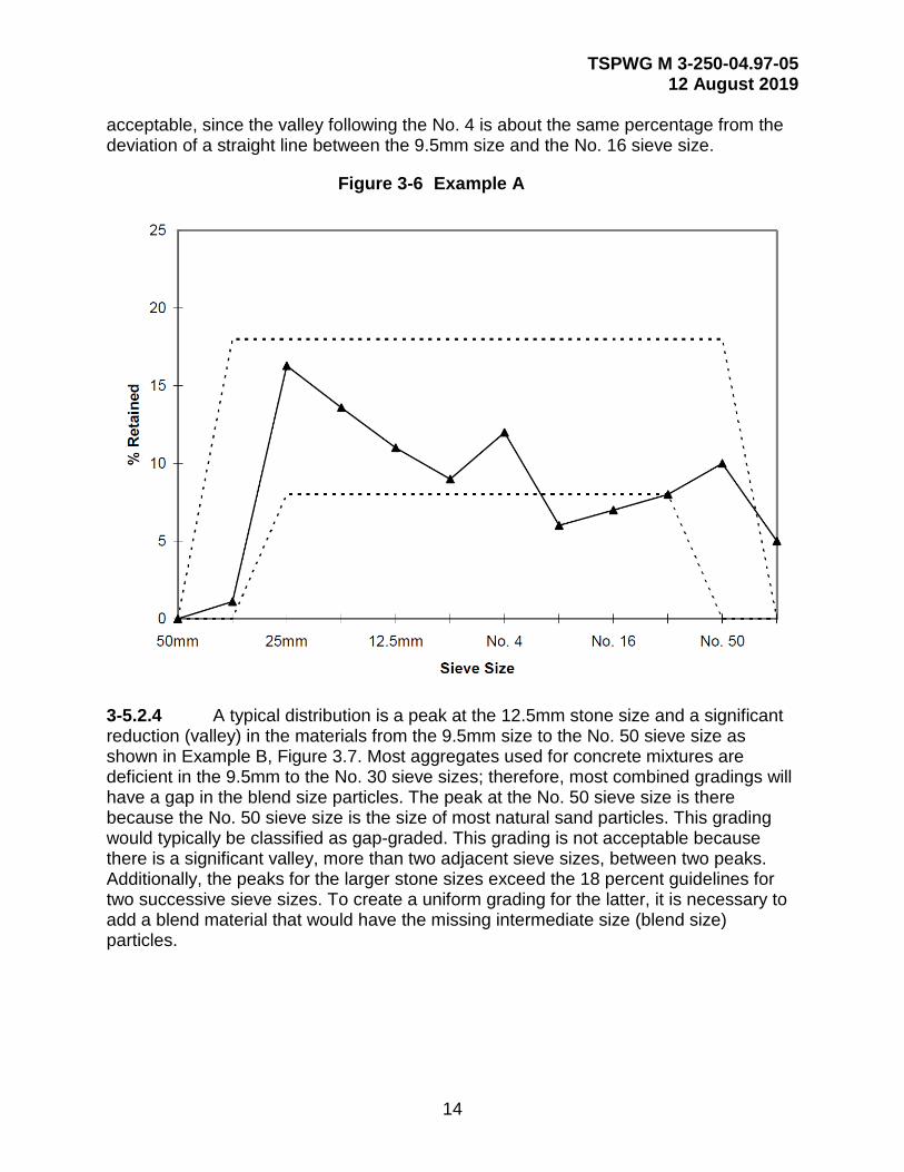
acceptable, since the valley following the No. 4 is about the same percentage from the deviation of a straight line between the 9.5mm size and the No. 16 sieve size.
Figure 3-6 Example A
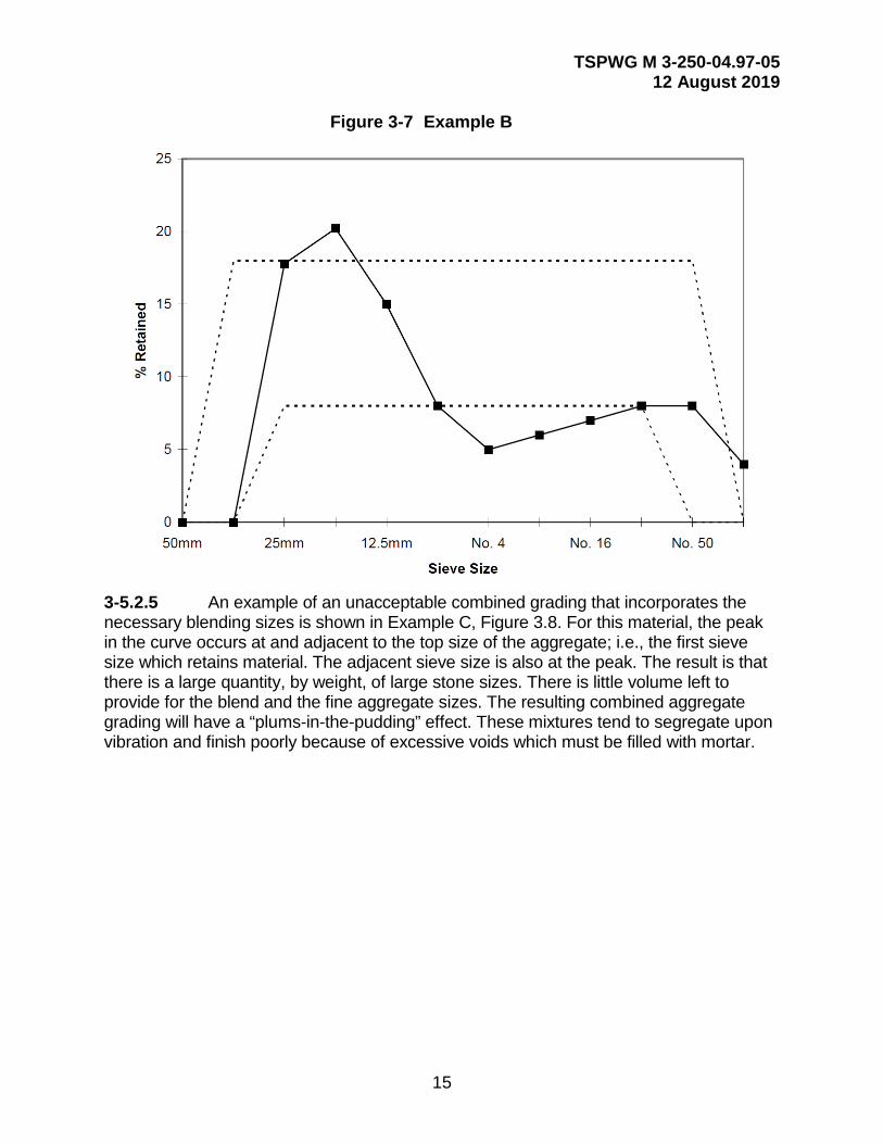
3-5.2.4 A typical distribution is a peak at the 12.5mm stone size and a significant reduction (valley) in the materials from the 9.5mm size to the No. 50 sieve size as shown in Example B, Figure 3.7. Most aggregates used for concrete mixtures are deficient in the 9.5mm to the No. 30 sieve sizes; therefore, most combined gradings will have a gap in the blend size particles. The peak at the No. 50 sieve size is there because the No. 50 sieve size is the size of most natural sand particles. This grading would typically be classified as gap-graded. This grading is not acceptable because there is a significant valley, more than two adjacent sieve sizes, between two peaks. Additionally, the peaks for the larger stone sizes exceed the 18 percent guidelines for two successive sieve sizes. To create a uniform grading for the latter, it is necessary to add a blend material that would have the missing intermediate size (blend size) particles.
TSPWG M 3-250-04.97-05 12 August 2019
15
Figure 3-7 Example B
3-5.2.5 An example of an unacceptable combined grading that incorporates the necessary blending sizes is shown in Example C, Figure 3.8. For this material, the peak in the curve occurs at and adjacent to the top size of the aggregate; i.e., the first sieve size which retains material. The adjacent sieve size is also at the peak. The result is that there is a large quantity, by weight, of large stone sizes. There is little volume left to provide for the blend and the fine aggregate sizes. The resulting combined aggregate grading will have a “plums-in-the-pudding” effect. These mixtures tend to segregate upon vibration and finish poorly because of excessive voids which must be filled with mortar.

TSPWG M 3-250-04.97-05 12 August 2019
16
Figure 3-8 Example C
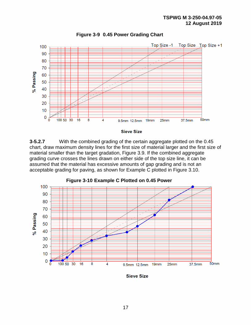
3-5.2.6 When doubts remain about the suitability of a certain combined grading, grading should be plotted on a 0.45 power curve, as shown in Figure 3.9. The grading should wander along the line associated with the top aggregate size. The meandering across and back of the top size line indicates where the material is gap-graded. To ascertain a reasonable amount of gap grading, the curve should be examined for the maximum departure from the maximum density line (top size line).
TSPWG M 3-250-04.97-05 12 August 2019
17
Figure 3-9 0.45 Power Grading Chart
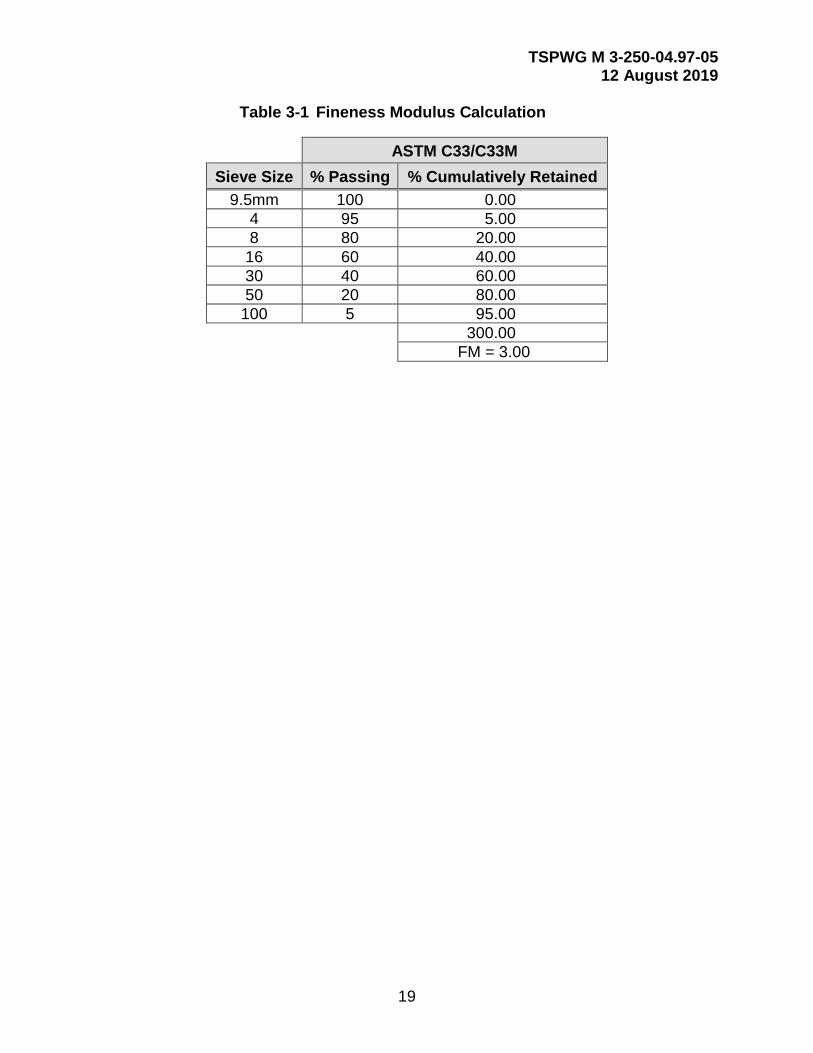
3-5.2.7 With the combined grading of the certain aggregate plotted on the 0.45 chart, draw maximum density lines for the first size of material larger and the first size of material smaller than the target gradation, Figure 3.9. If the combined aggregate grading curve crosses the lines drawn on either side of the top size line, it can be assumed that the material has excessive amounts of gap grading and is not an acceptable grading for paving, as shown for Example C plotted in Figure 3.10.
Figure 3-10 Example C Plotted on 0.45 Power

TSPWG M 3-250-04.97-05 12 August 2019
18
3-6 FINENESS MODULUS OF THE FINE AGGREGATE.
3-6.1 The fine aggregate, as delivered to the stockpile, should be graded within the limits of ASTM C33/C33M (Figure 3.11). The maximum limitation of ASTM C33/C33M for fineness modulus of 3.1 is NOT applicable for fine aggregate being used for conventional paving applications. The DoD minimum limitation for fineness modulus is 2.35, while the minimum limitation for fineness modulus according to ASTM C33 is 2.15, as shown in Figure 3.3. The fine aggregate should be well-graded and correspond to the general shape of the grading curves shown in Figure 3.5. For concrete placed by mechanical means, the fine aggregate should have a minimum percent passing the No. 50 and No. 100 sieves of 5 and 0, respectively. The fineness modulus is calculated by adding the total percentage of material in the fine aggregate sample that is coarser than each of the following sieves, and dividing the sum by 100. Sieves used for the analysis include 9.5mm, No. 4, No. 8, No. 16, No. 30, No. 50, and No. 100. Fine aggregate should be sampled according to ASTM D75/D75M prior to performing a sieve analysis according to ASTM C136.
Figure 3-11 Fine Aggregate Grading Limits
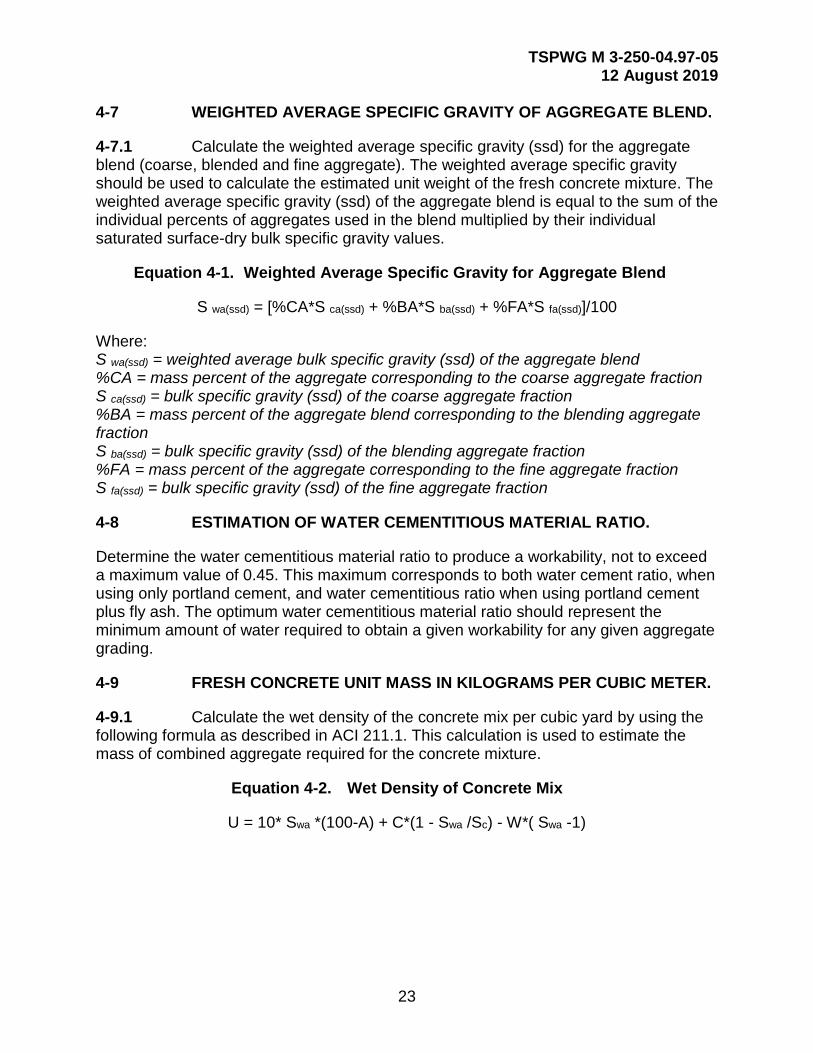
3-6.2 An example of the fineness modulus calculation is given in Table 3.1. The percent passing each of the specific sieves, 9.5mm, No. 4, No. 8, No. 16, No. 30, No. 50, and No. 100, is tabulated. The total amount of material coarser than each of the following sieves is tabulated next. The sum of the percent cumulatively retained is determined (30), and the sum is then divided by 100, resulting in a fineness modulus, or FM, of 3.00.
TSPWG M 3-250-04.97-05 12 August 2019
19
Table 3-1 Fineness Modulus Calculation
ASTM C33/C33M Sieve Size % Passing % Cumulatively Retained
9.5mm 100 0.00 4 95 5.00 8 80 20.00
16 60 40.00 30 40 60.00 50 20 80.00
100 5 95.00 300.00 FM = 3.00

TSPWG M 3-250-04.97-05 12 August 2019
20
This Page Intentionally Left Blank

TSPWG M 3-250-04.97-05 12 August 2019
21
CHAPTER 4 MIX PROPORTIONING
4-1 INTRODUCTION.
The procedure for selecting mixture proportions in this chapter applies to normal weight concrete to be placed by slipform or form-in-place machine paving techniques.
4-2 ESTIMATION OF WORKABILITY.
To estimate workability, one commonly used method is to measure slump in accordance with ASTM C143/C143M, Standard Test Method for Slump of Hydraulic-Cement Concrete. The workability of the mixture should be dictated by the type of field placement method proposed by the contractor. Mix workability should have a maximum slump of 25mm for slipform paving and a maximum slump of 75mm for form-in-place methods of field placement.
4-3 NOMINAL MAXIMUM SIZE OF COARSE AGGREGATE.
The nominal maximum size of coarse aggregate should be determined by the contractor based on the following guidelines: The nominal maximum size used for airfield pavements should be either 37.5mm, 25mm, or 19mm; and in geographical areas where ‘D’ cracking is known to be a problem, the nominal maximum size of coarse aggregate should be 19mm.
4-4 ESTIMATION OF CEMENTITIOUS MATERIAL CONTENT.
4-4.1 The minimum cementitious materials content should not be less than 335 kg/m3 (564 lb/yd3) of concrete, and the minimum portland cement content should not be less than 307 kg/m3 (517 lb/yd3) of concrete when fly ash is incorporated into the mixture. The amount of cementitious material is determined by the amount of portland cement plus the amount of fly ash. When Class F or C fly ash is utilized, as designated by ASTM C618, the mass of fly ash used in the mix should not be less than 15 percent nor more than 25 percent of the total cementitious material; i.e., the ratio of the mass of fly ash divided by the combined mass of fly ash and the mass of portland cement should not be less than 15 percent nor more than 25 percent of the total cementitious material.
4-4.2 When using the minimum amount of fly ash (15 percent), and using the minimum amount of portland cement described in paragraph 2-5.3, (307 kg/m3 (517 lb/yd3)), the following applies:
M(fa)/[M(fa) + M(pc)] = 0.15
M(fa)/[M(fa) + 307 kg/m3 ]= 0.15
M(fa) = 54 kg/m3 (91 lb/yd3)
M(cementitious material) = 307 kg/m3 + 54 kg/m3 =361 kg/m3 (608 lb/yd3)

TSPWG M 3-250-04.97-05 12 August 2019
22
4-4.3 When using the maximum amount of fly ash, 25 percent, and using the minimum amount of portland cement described in paragraph 2.5.3, of 307 kg/m3 (517 lb/yd3), the following applies:
M(fa)/[M(fa) + M(pc)] = 0.25
M(fa)/[M(fa) + 307 kg/m3] = 0.25
M(fa) = 102 kg/m3 (172 lb/yd3)
M(cementitious material) = 307 kg/m3 + 102 kg/m3 = 409 kg/m3 (689 lb/yd3)
4-5 ESTIMATION OF AIR CONTENT.
4-5.1 Determine the air content for the proposed mix from Table 4.1, based on the nominal maximum size aggregate and the type of exposure as indicated by weathering regions associated with the project location. The exposure definitions provided in EB001 apply.
Table 4-1 Target Air Content for Airfield Pavement Concrete
Target Air Content (Percent by Volume) Nominal Maximum Aggregate Size (mm)
Severe Exposure
Moderate Exposure
Mild Exposure
37.5mm 5-1/2 4-1/2 2-1/2 25mm 6 4-1/2 3 19mm 6 5 3-1/2
The air content of the delivered concrete should be within -1 to +2 percentage points of the table target values.7
4-6 COARSE AND FINE AGGREGATE AS SINGLE AGGREGATE BLEND.
The amount of coarse aggregate, blended aggregate, and fine aggregate should be treated as a single component of the mixture and determined from the limits set forth in the Combined Aggregate Proportioning Guide and the Percent Combined Aggregate Retained graph (Figures 3.1 and 3.2, respectively). Aggregate properties are determined by the contractor and should include dry-rodded unit weight, bulk specific gravity (saturated surface-dry), and percent absorption, for the coarse aggregate fraction. For the fine aggregate fraction, properties provided by the contractor should include bulk specific gravity (saturated surface-dry), percent absorption, and fineness modulus.
7Design and Control of Concrete Mixtures, EB001, Portland Cement Association.
TSPWG M 3-250-04.97-05 12 August 2019
23
4-7 WEIGHTED AVERAGE SPECIFIC GRAVITY OF AGGREGATE BLEND.
4-7.1 Calculate the weighted average specific gravity (ssd) for the aggregate blend (coarse, blended and fine aggregate). The weighted average specific gravity should be used to calculate the estimated unit weight of the fresh concrete mixture. The weighted average specific gravity (ssd) of the aggregate blend is equal to the sum of the individual percents of aggregates used in the blend multiplied by their individual saturated surface-dry bulk specific gravity values.
Equation 4-1. Weighted Average Specific Gravity for Aggregate Blend
S wa(ssd) = [%CA*S ca(ssd) + %BA*S ba(ssd) + %FA*S fa(ssd)]/100
Where: S wa(ssd) = weighted average bulk specific gravity (ssd) of the aggregate blend %CA = mass percent of the aggregate corresponding to the coarse aggregate fraction S ca(ssd) = bulk specific gravity (ssd) of the coarse aggregate fraction %BA = mass percent of the aggregate blend corresponding to the blending aggregate fraction S ba(ssd) = bulk specific gravity (ssd) of the blending aggregate fraction %FA = mass percent of the aggregate corresponding to the fine aggregate fraction S fa(ssd) = bulk specific gravity (ssd) of the fine aggregate fraction
4-8 ESTIMATION OF WATER CEMENTITIOUS MATERIAL RATIO.
Determine the water cementitious material ratio to produce a workability, not to exceed a maximum value of 0.45. This maximum corresponds to both water cement ratio, when using only portland cement, and water cementitious ratio when using portland cement plus fly ash. The optimum water cementitious material ratio should represent the minimum amount of water required to obtain a given workability for any given aggregate grading.
4-9 FRESH CONCRETE UNIT MASS IN KILOGRAMS PER CUBIC METER.
4-9.1 Calculate the wet density of the concrete mix per cubic yard by using the following formula as described in ACI 211.1. This calculation is used to estimate the mass of combined aggregate required for the concrete mixture.
Equation 4-2. Wet Density of Concrete Mix
U = 10* Swa *(100-A) + C*(1 - Swa /Sc) - W*( Swa -1)

TSPWG M 3-250-04.97-05 12 August 2019
24
Where: U = the mass of fresh concrete per cubic meter, in kilograms. Swa = the weighted average saturated surface-dry bulk specific gravity of the coarse and
fine aggregate as determined in Step 6. Sc = the specific gravity of portland cement, or a portland cement-fly ash blend.
(Note: The generally accepted value for the specific gravity of portland cement is 3.15. A weighted average density for a portland cement-fly ash blend would be determined as in Step 6.)
A = air content in percent as determined in Step 4. W = the mixing water required with SSD aggregate in kilograms per cubic meter, as determined in Step 7. C = the cementitious materials content in kilograms per cubic meter, as determined in Step 3.
4-10 ESTIMATION OF COMBINED AGGREGATE QUANTITY.
The total blended aggregate (coarse, blended and fine) required for the mix, in kg/m3, is calculated by subtracting the quantity of required water and cementitious material in kg/m3 of concrete from the unit mass of fresh concrete.
4-11 ADJUSTMENTS FOR AGGREGATE MOISTURE.
The aggregate quantities actually weighed out for the concrete must allow for moisture in the aggregates. Bulk specific gravities on the basis of mass of saturated surface-dry aggregate and absorptions of both coarse and fine aggregates are determined according to standard test methods described in ASTM C127, Standard Test Method for Relative Density (Specific Gravity) and Absorption of Coarse Aggregate, and C128, Standard Test Method for Relative Density (Specific Gravity) and Absorption of Fine Aggregate, respectively. Total moisture contents for both coarse and fine aggregates are determined according the ASTM C566, Standard Test Method for Total Evaporative Moisture Content of Aggregate by Drying.
4-12 TRIAL BATCH ADJUSTMENTS.
4-12.1 The calculated mix proportions should be checked by preparing trial batches and testing in accordance with ASTM C192/C192M, Standard Practice for Making and Curing Concrete Test Specimens in the Laboratory. The concrete should be checked for unit weight and yield (ASTM C138/C138M, Standard Test Method for Density (Unit Weight), Yield, and Air Content (Gravimetric) of Concrete; for air content (ASTM C231/C231M, Standard Test Method for Air Content of Freshly Mixed Concrete by the Pressure Method); and for determining the minimum required flexural strength (ASTM C78/C78M, Standard Test Method for Flexural Strength of Concrete (Using Simple Beam with Third-Point Loading)).
4-12.2 Proportion the concrete for the minimum flexural strength required by the specification at 90 days of age determined using the procedures of ASTM C78/C78M. Concrete beam specimens should be tested at 7, 14, 28, and 90 days.

TSPWG M 3-250-04.97-05 12 August 2019
25
4-12.3 Adjustments to the mix to provide the required workability and air content should be made by adjusting water content (though not to exceed a water cement ratio of 0.45) and by using chemical admixtures. Once the desired strength requirements are satisfied, two other concrete mixtures should be prepared having two different water cement ratios to evaluate their effects on flexural strength at 90 days.
4-13 FIELD TRIALS.
The contractor should place a test strip of pavement representing two hours of mixing and placing operations , using the concrete and equipment that will be used to perform the work. The contractor should demonstrate that positive control of edge slump and surface finish can be established and maintained. The contractor should also demonstrate that this control can be maintained when environmental conditions change.

TSPWG M 3-250-04.97-05 12 August 2019
26
This Page Intentionally Left Blank
TSPWG M 3-250-04.97-05 12 August 2019
27
CHAPTER 5 SAMPLE COMPUTATIONS
5-1 EXAMPLE 1.
5-1.1 Description.
This example illustrates how fine aggregate that does not satisfy ASTM C33/C33M grading requirements falls into the correct zone for slipform paving when combined with coarse aggregate in the correct proportions.
5-1.1.1 Concrete is required for an airfield taxiway at a Base, in Florida. The exposure is considered mild as designated by ACI 211.1. The limits for deleterious substances and physical property requirements of the coarse aggregate and fine aggregate are found in Table 3, class designation 1N, and Table 1, respectively, in ASTM C33/C33M. The contractor plans to use slipform paving equipment to place the concrete, requiring the workability of the concrete mixture be appropriate for use with that type of equipment. Structural considerations require a flexural strength of 725 psi (5 megapascals (MPa)) at 90 days. Type I portland cement will be used having a specific gravity of 3.15.
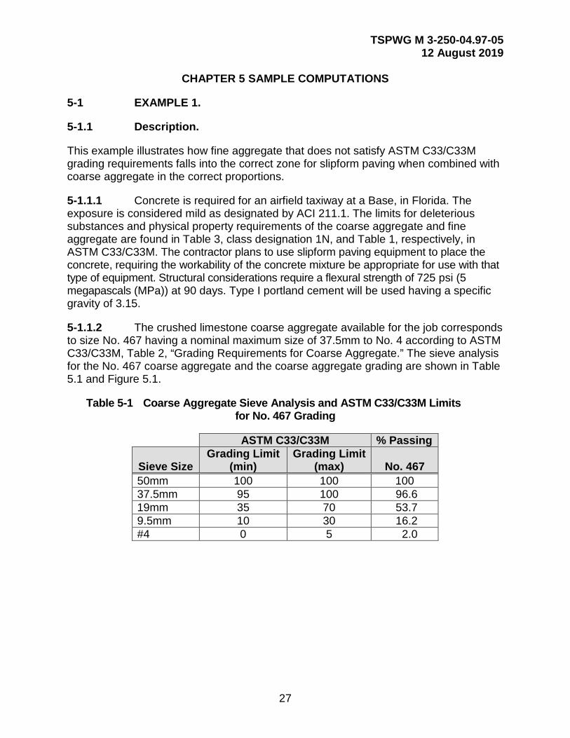
5-1.1.2 The crushed limestone coarse aggregate available for the job corresponds to size No. 467 having a nominal maximum size of 37.5mm to No. 4 according to ASTM C33/C33M, Table 2, “Grading Requirements for Coarse Aggregate.” The sieve analysis for the No. 467 coarse aggregate and the coarse aggregate grading are shown in Table 5.1 and Figure 5.1.
Table 5-1 Coarse Aggregate Sieve Analysis and ASTM C33/C33M Limits for No. 467 Grading
ASTM C33/C33M % Passing
Sieve Size Grading Limit
(min) Grading Limit
(max) No. 467 50mm 100 100 100 37.5mm 95 100 96.6 19mm 35 70 53.7 9.5mm 10 30 16.2 #4 0 5 2.0

TSPWG M 3-250-04.97-05 12 August 2019
28
Figure 5-1 Grading of 37.5mm Nominal Coarse Aggregate and ASTM C33/C33M Grading Limits
5-1.1.3 The coarse aggregate has a bulk specific gravity (saturated surface-dry) of 2.69 and an absorption of 0.33 percent. The dry-rodded mass of the coarse aggregate is 1650 kg/m3 (2781 lb/yd3).
5-1.1.4 The fine aggregate is a manufactured sand consisting of lime rock screenings designated as Florida Department of Transportation (FDOT) Code #25 - Fine Screenings, and has a bulk specific gravity (saturated surface-dry) of 2.68, an absorption of 1.71 percent, and fineness modulus of 3.15. The fine aggregate sieve analysis, fineness modulus calculation, and grading are shown in Table 5.2 and Figure 5.2. The minimum fineness modulus required by DoD is 2.3, and the maximum limitation of ASTM C33/C33M for fineness modulus of 3.1 is NOT applicable for fine aggregate being used in this example. The fineness modulus (FM) is determined by summing the percent cumulative retained values from the sieves shown in Table 5.2, and the result (315), divided by 100, yields a FM value of 3.15.
TSPWG M 3-250-04.97-05 12 August 2019
29
Table 5-2 Fine Aggregate Sieve Analysis and ASTM C33/C33M Fine Aggregate Grading
ASTM C33 % Passing % Cumulative
Retained
Sieve Size Grading Limit
(min) Grading Limit
(max) FDOT #25 FDOT #25 9.5mm 100 100 100 0
4 95 100 89 11 8 80 100 73 27
16 50 85 47 53 30 25 60 38 62 50 5 30 25 75
100 0 10 13 87 315
Figure 5-2 Grading of Fine Aggregate and Grading Limits of Figure 3.11
5-1.2 CALCULATIONS.
The quantities of ingredients per cubic meter of concrete are calculated as follows:
5-1.2.1 Step 1.
Mix workability was determined by the contractor as appropriate for placement by a slipform paver.

TSPWG M 3-250-04.97-05 12 August 2019
30
5-1.2.2 Step 2.
The locally available coarse aggregate having a nominal maximum size of 37.5mm, and graded from 37.5mm to No. 4, has been determined to be suitable for this paving project.
5-1.2.3 Step 3.
The amount of cementitious material in the form of Type I portland cement was chosen to be 335 kg/m3 (564 lb/yd3) of concrete, meeting the minimum cementitious materials factor specified in this TSPWG M.
5-1.2.4 Step 4.
From Table 4.1, the amount of air, based on the nominal maximum aggregate size of 37.5mm, and being in a mild exposure region, should be 2.5 percent within -1 to +2 percentage points.
5-1.2.5 Step 5.
The ratio of coarse to fine aggregate for the combined aggregate is determined from both the Aggregate Proportioning Guide and the Percent Combined Aggregate Retained graph. The amount of coarse aggregate and fine aggregate is treated as a single component of the mix, and the amount of the combined aggregate will be determined in Step 9 of this procedure.
5-1.2.5.1 The individual coarse and fine aggregate sieve analyses and the combined sieve analysis based on 58 percent coarse and 42 percent fine aggregate are shown in Table 5-3. This ratio is determined by trial and error until the combination of available aggregates meets the requirements specified by the Aggregate Proportioning Guide and the Percent Combined Aggregate Retained graph in Chapter 3. The workability factor (WF), defined as the amount of combined aggregate material passing the No. 8 sieve multiplied by 100, is 30.66. The coarseness factor (CF) (defined as the percent of combined aggregate retained above the 9.5mm sieve divided by the percent retained above the No. 8 sieve, multiplied by 100) is 70.1.

TSPWG M 3-250-04.97-05 12 August 2019
31
Table 5-3 Sieve Analysis of Combined Aggregate
% Passing Combined Sieve Size
Coarse Aggregate
Fine Aggregate % Passing
% Cumulative Retained % Retained
50mm 100.0 100 100.00 0.00 0.00 37.5mm 96.6 100 98.03 1.97 1.97 25mm 68.4 100 81.67 18.33 16.36 19mm 53.7 100 73.15 26.85 8.53 12.5mm 30.2 100 59.52 40.48 13.63 9.5mm 16.2 100 51.40 48.60 8.12 No. 4 2.0 89 38.54 61.46 12.86 No. 8 0 73 30.66 69.34 7.88 No. 16 47 19.74 80.26 10.92 No. 30 38 15.96 84.04 3.78 No. 50 25 10.50 89.50 5.46 No. 100 13 5.46 94.54 5.04 WF=30.66 CF=70.10
5-1.2.5.2 The plot of the combined aggregate on the Aggregate Proportioning Guide, and the Percent Aggregate Retained graph are shown in Figures 5.3 and 5.4, respectively. The 58 percent coarse and 42 percent fine combined aggregate data point (Figure 5.3) is located just above the centerline within the workability box, which is just where it should be for placing concrete using slipform paving equipment. Since the combined aggregate data point is close to being outside of the workability box and does not include the daily variance, frequent checks on the combined aggregate gradation will be required. The Percent Combined Aggregate Retained plot of the combined aggregate (Figure 5.4) shows no significant valley or peak between the 9.5mm sieve size and the finest reporting sieve size.

TSPWG M 3-250-04.97-05 12 August 2019
32
Figure 5-3 Aggregate Proportioning Guide for Combined Aggregate
Figure 5-4 Percent Combined Aggregate Retained
5-1.2.6 Step 6.
The weighted average specific gravity (ssd) for the combined aggregate is calculated from the ratio of coarse aggregate to fine aggregate that satisfies the aggregate grading control requirements as specified by the Aggregate Proportioning Guide, the Percent

TSPWG M 3-250-04.97-05 12 August 2019
33
Combined Aggregate Retained criteria, and the bulk specific gravities (ssd) of the individual aggregate fractions. The ratio that satisfies the criteria of Step 5 was 58 percent by mass coarse aggregate and 42 percent by mass fine aggregate. Therefore, the weighted average specific gravity (ssd) of the aggregate blend is calculated by the following:
Equation 5-1. Weighted Average Specific Gravity (ssd) of Aggregate Blend
Swa(ssd) = (%CA*Sca(ssd) + %BA*Sba(ssd) + %FA*Sfa(ssd))/100
Where: %CA = 58 Sca(ssd) = 2.69 %BA = 0 Sba(ssd) = 0 %FA = 42 Sfa(ssd) = 2.68 Swa(ssd) = ((58)*(2.69) + (42)*(2.68))/100 = 2.69
5-1.2.7 Step 7.
The water cementitious ratio required to produce the required workability for slipform paver placement can be determined by laboratory testing and field trial batches, and must not exceed the 0.45 maximum. The initial estimate of water cementitious ratio was taken to be between 0.40 and 0.42 and trial batches made. A starting point for the water cementitious ratio used in this example was 0.40. A water content of 134 kg/m3 (225.8 lb/yd3) of concrete is required based on a cement content of 335 kg/m3 (564 lb/yd3) of concrete and a water cementitious ratio of 0.4.
Equation 5-2. Water Cementitious Ratio
W = (335 kg/m3)*(0.4) = 134 kg/m3
5-1.2.8 Step 8.
The unit mass of fresh concrete per cubic meter of concrete is calculated next using the formula described in ACI 211.1.
Equation 5-3. Unit Mass of Fresh Concrete
U = 10*Swa*(100-A) + C*(1-Swa/Sc) - W*(Swa-1)

TSPWG M 3-250-04.97-05 12 August 2019
34
Where: Swa = 2.69 Sc = 3.15 A = 2.5 percent W = 134 kg C = 335 kg U = 2445 kg/m3
5-1.2.9 Step 9.
The total amount of combined aggregate required for the mix in kg/m3 (lb/yd3) of concrete is calculated by subtracting the amount of required water and cementitious material from the unit mass of fresh concrete determined in Step 8. For one cubic meter of concrete:
Equation 5-4. Total Combined Aggregate Required for Mix
2445 kg/m3 (4121 lb/yd3) total mass - 335 kg/m3 (564 lb/yd3) of cement - 134 kg/m3 (225.8 lb/yd3) of water = 1976 kg/m3 (3325 lb/yd3) of combined aggregate (ssd)
Of the 1976 kg/m3 (3330 lb/yd3) of combined aggregate calculated in Step 9, 58 percent or 1146 kg/m3 (1931 lb/yd3) coarse aggregate(ssd), and 42 percent or 830 kg/m3 (1399 lb/yd3) is fine aggregate(ssd).
5-1.2.9.1 The estimated batch weights for a cubic meter of concrete, in kilograms are:
Water (mix) 134 kg Cement 335 kg Coarse aggregate (ssd) 1146 kg Fine aggregate (ssd) 830 kg Total mass 2445 kg
5-1.2.9.2 From an absolute volume basis per cubic meter are:
Water (mix) 134/1000 = 0.134 Cement 335/(3.15*1000) = 0.1063 Coarse aggregate (ssd) 1146/(2.69*1000) = 0.426 Fine aggregate (ssd) 830/(2.68*1000) = 0.3097 Air 0.025*1.0 = 0.025 Total volume 1.00 m3
TSPWG M 3-250-04.97-05 12 August 2019
35
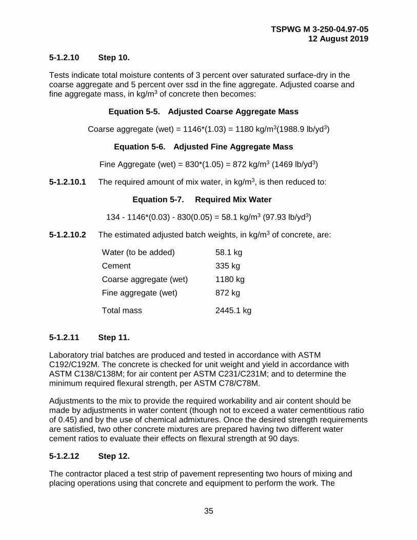
5-1.2.10 Step 10.
Tests indicate total moisture contents of 3 percent over saturated surface-dry in the coarse aggregate and 5 percent over ssd in the fine aggregate. Adjusted coarse and fine aggregate mass, in kg/m3 of concrete then becomes:
Equation 5-5. Adjusted Coarse Aggregate Mass
Coarse aggregate (wet) = 1146*(1.03) = 1180 kg/m3(1988.9 lb/yd3)
Equation 5-6. Adjusted Fine Aggregate Mass
Fine Aggregate (wet) = 830*(1.05) = 872 kg/m3 (1469 lb/yd3)
5-1.2.10.1 The required amount of mix water, in kg/m3, is then reduced to:
Equation 5-7. Required Mix Water
134 - 1146*(0.03) - 830(0.05) = 58.1 kg/m3 (97.93 lb/yd3)
5-1.2.10.2 The estimated adjusted batch weights, in kg/m3 of concrete, are:
Water (to be added) 58.1 kg Cement 335 kg Coarse aggregate (wet) 1180 kg Fine aggregate (wet) 872 kg
Total mass 2445.1 kg
5-1.2.11 Step 11.
Laboratory trial batches are produced and tested in accordance with ASTM C192/C192M. The concrete is checked for unit weight and yield in accordance with ASTM C138/C138M; for air content per ASTM C231/C231M; and to determine the minimum required flexural strength, per ASTM C78/C78M.
Adjustments to the mix to provide the required workability and air content should be made by adjustments in water content (though not to exceed a water cementitious ratio of 0.45) and by the use of chemical admixtures. Once the desired strength requirements are satisfied, two other concrete mixtures are prepared having two different water cement ratios to evaluate their effects on flexural strength at 90 days.
5-1.2.12 Step 12.
The contractor placed a test strip of pavement representing two hours of mixing and placing operations using that concrete and equipment to perform the work. The
TSPWG M 3-250-04.97-05 12 August 2019
36
contractor demonstrated that positive control of edge slump and surface finish could be established and maintained. He also demonstrated that this control could be maintained according to environmental conditions.
5-2 EXAMPLE 2.
5-2.1 Description.
5.2.1.2 Concrete is required for an airfield runway at a Base, in Kansas. The exposure is considered severe, as designated by ACI 211.1. The limits for deleterious substances and physical property requirements of the coarse aggregate and fine aggregate can be found in Table 3, class designation 4S, and Table 1, respectively, in ASTM C33/C33M. The contractor plans to use slipform paving equipment to place the concrete, requiring the workability of the concrete mixture be appropriate for use with that type of equipment. Structural considerations require a flexural strength of 5 MPa (725.2 psi) at 90 days. Type II portland cement will be used having a specific gravity of 3.15.
5.2.1.3 The crushed limestone coarse aggregate available for the job corresponds to size No. 67 having a nominal maximum size of 19mm to No. 4 according to ASTM C33/C33M, Table 2. The sieve analysis for the No. 67 coarse aggregate and the coarse aggregate grading are shown in Table 5.4 and Figure 5.5.
Table 5-4 Coarse Aggregate Sieve Analysis and ASTM C33/C33M Limits for No. 67 Grading
ASTM C33 % Passing
Sieve Size Grading Limit
(min) Grading Limit
(max) No. 67 25mm 100 100 100.00 19mm 90 100 97.24 9.5mm 20 55 33.59 #4 0 10 2.88 #8 0 5 0.57 #16 0 0 0.00

TSPWG M 3-250-04.97-05 12 August 2019
37
Figure 5-5 Grading of 19mm Nominal Coarse Aggregate and ASTM C33/C33M Grading Limits
5-2.1.4 The coarse aggregate has a bulk specific gravity (saturated surface dry) of 2.69 and an absorption of 0.33 percent. The dry-rodded unit mass of the coarse aggregate is 1570 kg/m3 (2646 lb/yd3).
5-2.1.5 The fine aggregate is a manufactured stone sand, and has a bulk specific gravity (saturated surface-dry) of 2.76, an absorption of 3.3 percent, and fineness modulus of 3.12. The fine aggregate sieve analysis, fineness modulus calculation, and grading are shown in Table 6.5 and Figure 6.6, respectively. The minimum fineness modulus required by the DoD is 2.3, and the maximum limitation of ASTM C33/C33M for fineness modulus of 3.1 is NOT applicable for fine aggregate being used in this example. The fineness modulus (FM) is determined by summing the percent cumulative retained values from the sieves shown in Table 6.5, and the result (312), divided by 100, yields a FM value of 3.12.

TSPWG M 3-250-04.97-05 12 August 2019
38
Table 5-5 Fine Aggregate Sieve Analysis and ASTM C33/C33M Fine Aggregate Grading
ASTM C33/C33M % Passing % Cumulative
Retained
Sieve Size Grading Limit
(min) Grading Limit
(max) Stone Sand Stone Sand 9.5mm 100 100 100 0
4 95 100 99 1 8 80 100 86 14 16 50 85 50 50 30 25 60 30 70 50 5 30 16 84
100 0 10 7 93 312
Figure 5-6 Grading of Fine Aggregate and Grading Limits of Figure 3.11
5-2.2 Calculations.
The quantities of ingredients per cubic meter of concrete are calculated as shown in Steps 1 through 12.
5-2.2.1 Step 1.
Mix workability was determined by the contractor to be appropriate for placement by a slipform paver.

TSPWG M 3-250-04.97-05 12 August 2019
39
5-2.2.2 Step 2.
The locally available coarse aggregate having a nominal maximum size of 19mm and graded from 19mm to No. 4 has been determined to be suitable for this paving project.
5-2.2.3 Step 3.
The amount of cementitious material in the form of Type II portland cement was chosen to be 363 kg/m3 (611.8 lb/yd3) of concrete, meeting the minimum cementitious materials factor specified in this TSPWG M.
5-2.2.4 Step 4.
From Table 4.1, the amount of air, based on the nominal maximum aggregate size of 19mm, and being in a severe exposure region, should be 6 percent, within -1 to +2 percentage points.
5-2.2.5 Step 5.
The ratio of coarse to fine aggregate for the combined aggregate is determined from both the Aggregate Proportioning Guide and the Percent Combined Aggregate Retained graph. The amount of coarse aggregate and fine aggregate is treated as a single component of the mix, and the amount of the combined aggregate will be determined in Step 9.
5-2.2.5.1 The individual coarse and fine aggregate sieve analyses and the combined sieve analysis based on 62 percent coarse and 38 percent fine aggregate are shown in Table 5.6. This ratio is determined by trial and error until the combination of available aggregates meets the requirements specified by the Aggregate Proportioning Guide and the Percent Combined Aggregate Retained graph . The workability factor, defined as the amount of combined aggregate material passing the No. 8 sieve, is shown to be 33.03. An additional 1.25 percent is added to the 33.03 determined from the percent passing the No. 8 sieve, since the cement factor of 363 kg/m3 (611.8 lb/yd3) is 28 kg/m3 (47 lb/yd3) more than the base cement factor. Therefore, the adjusted workability factor is 34.28. A 2.5 percent adjustment in the workability factor is required for each 56 kg/m3 (94 lb/yd3) of cement above the base cement factor of 335 kg/m3 (564 lb/yd3). The coarseness factor, defined as the percent of combined aggregate retained above the 9.5mm sieve divided by combined aggregate retained above the No. 8 sieve multiplied by 100, is 61.48.
TSPWG M 3-250-04.97-05 12 August 2019
40
Table 5-6 Sieve Analysis of Combined Aggregate
% Passing Combined Sieve Size
Coarse Aggregate
Fine Aggregate %Passing
% Cumulative Retained % Retained
1 100.00 100 100.00 0.00 0.00 3/4 97.24 100 98.29 1.71 1.71 1/2 60.65 100 75.60 24.40 22.69 3/8 33.59 100 58.83 41.17 16.70 4 2.88 99 39.41 60.59 19.42 8 0.57 86 33.03 66.97 6.37
16 0.00 50 19.00 81.00 14.03 30 30 11.40 88.60 7.60 50 16 6.08 93.92 5.32
100 7 2.66 97.34 3.42 WF=33.03 CF=61.48
5-2.2.5.2 The plots of combined aggregate on the Aggregate Proportioning Guide and the Percent Aggregate Retained graph are shown in Figures 5.7 and 5.8, respectively. The 60 percent coarse and 40 percent fine aggregate combined aggregate data point in Figure 5.7 is located just above the centerline within the workability box, which is just where it should be for placing concrete using slipform paving equipment. However, this does not include the expected daily variance. The Percent Combined Aggregate Retained plot of the combined aggregate in Figure 5.8 shows no significant valley or peak between the 9.5mm sieve size and the finest reporting sieve size.
Figure 5-7 Aggregate Proportioning Guide for Combined Aggregate

TSPWG M 3-250-04.97-05 12 August 2019
41
Figure 5-8 Percent Combined Aggregate Retained
5-2.2.6 Step 6.
The weighted average specific gravity (ssd) for the combined aggregate is calculated from the ratio of coarse aggregate to fine aggregate that satisfies the aggregate grading control requirements as specified by the Aggregate Proportioning Guide and Percent Combined Aggregate Retained criteria, and the bulk specific gravities (ssd) of the individual aggregate fractions. The ratio that satisfies the criteria of Step 5 was 62 percent by weight coarse aggregate and 38 percent by weight fine aggregate. Therefore, the weighted average specific gravity (ssd) of the aggregate blend is calculated by Equation 5-8:
Equation 5-8. Weighted Average Specific Gravity (ssd) for Combined Aggregate
Swa(ssd) = (%CA*Sca(ssd) + %BA*Sba(ssd) + %FA*Sfa(ssd))/100
Where: %CA = 62 Sca(ssd) = 2.69 %BA = 0 Sba(ssd) = 0 %FA = 38 Sfa(ssd) = 2.76 Swa(ssd) = ((62)*(2.69) + (38)*(2.76))/100 = 2.72

TSPWG M 3-250-04.97-05 12 August 2019
42
5-2.2.7 Step 7.
The water cementitious ratio required to produce the required workability for slipform paver placement can be determined by laboratory testing and field trial batches, and must not exceed the 0.45 maximum. The initial estimate of water cementitious ratio was taken to be between 0.40 and 0.42, and trial batches made. A starting point for the water cementitious ratio used in this example was 0.42. A water content of 152 kg/m3 (256 lb/yd3) of concrete is required, based on a cement content 363 kg/m3 (611.8 lb/yd3) of concrete and a water cementitious ratio of 0.42.
Equation 5-9. Water Cementitious Ratio
W = (363 kg/m3)*(0.42) = 152 kg/m3
5-2.2.8 Step 8.
The unit mass of fresh concrete per cubic meter of concrete is calculated next using the formula described in ACI 211.1.
Equation 5-10. Unit Mass of Fresh Concrete
U = 10*Swa*(100-A) + C*(1-Swa/Sc) - W*(Swa-1)
Where: Swa = 2.72 Sc = 3.15 A = 6 percent W = 152 kg C = 363 kg U = 2345 kg/m3
5-2.2.9 Step 9.
The total amount of combined aggregate required for the mix in kg/m3 (lb/yd3) of concrete is calculated by subtracting the amount of required water and cementitious material from the unit mass of fresh concrete determined in Step 8. For one cubic meter of concrete:
Equation 5-11. Total Combined Aggregate Required
2345 kg/m3 (3954 lb/yd3) total mass - 363 kg/m3 (611 lb/yd3) of cement - 152 kg/m3 (256.6 lb/yd3) of water = 1830 kg/m3 (3078 lb/yd3) of combined aggregate(ssd)
5-2.2.9.1 Of the 1830 kg/m3 (3084 lb/yd3) of combined aggregate calculated in Step 9, 62 percent or 1135 kg/m3 (1912 lb/yd3) is coarse aggregate(ssd), and 38 percent or 695 kg/m3 (1172 lb/yd3) is fine aggregate (ssd).
5-2.2.9.2 The estimated batch weights for a cubic meter of concrete, in kilograms are:
TSPWG M 3-250-04.97-05 12 August 2019
43
Water (mix) 152 kg Cement 363 kg Coarse aggregate (ssd) 1135 kg Fine aggregate (ssd) 695 kg Total weight 2345 kg
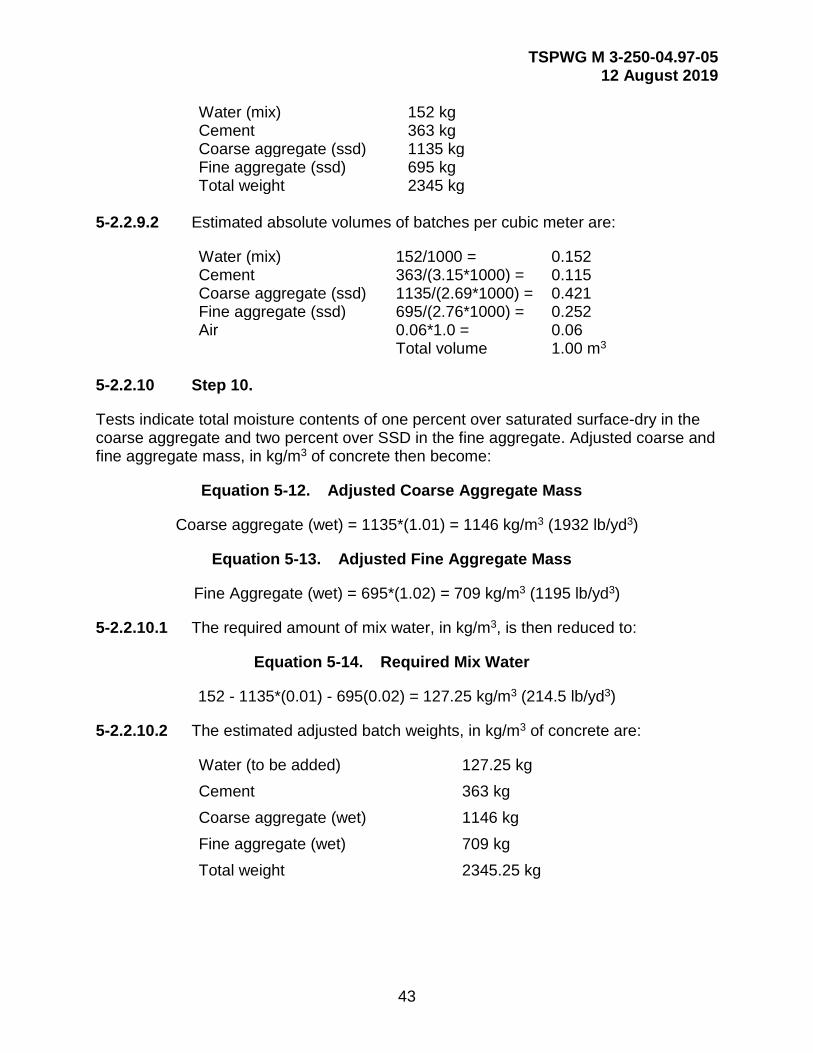
5-2.2.9.2 Estimated absolute volumes of batches per cubic meter are:
Water (mix) 152/1000 = 0.152 Cement 363/(3.15*1000) = 0.115 Coarse aggregate (ssd) 1135/(2.69*1000) = 0.421 Fine aggregate (ssd) 695/(2.76*1000) = 0.252 Air 0.06*1.0 = 0.06 Total volume 1.00 m3
5-2.2.10 Step 10.
Tests indicate total moisture contents of one percent over saturated surface-dry in the coarse aggregate and two percent over SSD in the fine aggregate. Adjusted coarse and fine aggregate mass, in kg/m3 of concrete then become:
Equation 5-12. Adjusted Coarse Aggregate Mass
Coarse aggregate (wet) = 1135*(1.01) = 1146 kg/m3 (1932 lb/yd3)
Equation 5-13. Adjusted Fine Aggregate Mass
Fine Aggregate (wet) = 695*(1.02) = 709 kg/m3 (1195 lb/yd3)
5-2.2.10.1 The required amount of mix water, in kg/m3, is then reduced to:
Equation 5-14. Required Mix Water
152 - 1135*(0.01) - 695(0.02) = 127.25 kg/m3 (214.5 lb/yd3)
5-2.2.10.2 The estimated adjusted batch weights, in kg/m3 of concrete are:
Water (to be added) 127.25 kg Cement 363 kg Coarse aggregate (wet) 1146 kg Fine aggregate (wet) 709 kg Total weight 2345.25 kg

TSPWG M 3-250-04.97-05 12 August 2019
44
5-2.2.11 Step 11.
Laboratory trial batches are produced and tested in accordance with ASTM C192/ C192M. The concrete is checked for unit weight and yield in accordance with ASTM C138/C138M; for air content per ASTM C231/C231M; and to determine the minimum required flexural strength per ASTM C78/C78M.
Adjustments to the mix to provide the required workability and air content should be made by adjustments in water content (though not to exceed a water cementitious ratio of 0.45) and by the use of chemical admixtures. Once the desired strength requirements were satisfied, two other concrete mixtures were prepared having two different water cement ratios to evaluate their effect on flexural strength at 90 days.
5-2.2.12 Step 12.
The contractor placed a test strip of pavement representing two hours of mixing and placing operations, using that concrete and equipment to perform the work. The contractor demonstrated that positive control of edge slump and surface finish could be established and maintained. He also demonstrated that this control could be maintained under environmental conditions.

TSPWG M 3-250-04.97-05 12 August 2019
45
APPENDIX A BEST PRACTICES [RESERVED]

TSPWG M 3-250-04.97-05 12 August 2019
46
This Page Intentionally Left Blank

TSPWG M 3-250-04.97-05 12 August 2019
47
APPENDIX B GLOSSARY
B-1 ACRONYMS
A air
ACI American Concrete Institute
ACPA American Concrete Paving Association
AFCEC/CO Air Force Civil Engineer Center, Operations Directorate
ASCE American Society of Civil Engineers
AFIMSC Air Force Installation Management Support Center
ASTM American Society for Testing and Materials
ba blending aggregate
C cement
ca coarse aggregate
CA combined aggregate
CF coarseness factor
CRD-C Construction Research and Development-Center
DoD Department of Defense
DOT Department of Transportation
fa fly ash
FA (also fa) fine aggregate
FDOT Florida Department of Transportation
FM fineness modulus
HQUSACE Headquarters United States Army Corps of Engineers
kg kilogram
kg/m3 kilograms per cubic meter
lb/yd3 pounds per cubic yard
TSPWG M 3-250-04.97-05 12 August 2019
48
M material
m3 cubic meter
mm millimeter
MPa megapascal
NAVFAC Naval Facilities Command
P portland
pc Portland cement
PCA Portland Cement Association
psi pounds per square inch
ssd specific gravity
TSPWG M Tri-Service Pavements Working Group Manual
U unit
UFC Unified Facilities Criteria
USACE/ERDC U.S. Army Corps of Engineers/Engineering Research and Development Center
W water
wa weighted average
WF workability factor

TSPWG M 3-250-04.97-05 12 August 2019
49
APPENDIX C REFERENCES
UNIFIED FACILITIES CRITERIA
http://www.wbdg.org/ffc/dod/unified-facilities-criteria-ufc
UFC 1-200-01, DoD Building Code (General Building Requirements)
ARMY CORPS OF ENGINEERS HANDBOOK FOR CONCRETE AND CEMENT
https://www.wbdg.org/ffc/army-coe/standards#sts=Handbook%20for%20Concrete%20and%20Cement
CRD-C 400, Requirements for Water for Use in Mixing or Curing Concrete
AMERICAN CONCRETE INSTITUTE.
https://www.concrete.org/store/productdetail.aspx?ItemID=211191&Language=English
211.1, Standard Practice for Selecting Proportions for Normal, Heavyweight, and Mass Concrete
Shilstone, James M. Sr. June,1990. Concrete Mixture Optimization. Concrete International.
AMERICAN CONCRETE PAVEMENT ASSOCIATION
www.acpa.org
Technical Bulletin TB004.02P, Fast Track Concrete Pavements
Gress, D.L. June 12, 1996. Recommendations for Mitigating Early Distress in Concrete Pavements. Presented to the American Concrete Pavement Association Durability Committee.
AMERICAN SOCIETY FOR TESTING AND MATERIALS
https://www.astm.org/
C33/C33M, Standard Specification for Concrete Aggregates
C78/C78M, Standard Test Method for Flexural Strength of Concrete (Using Simple Beam with Third-Point Loading)
C127, Standard Test Method for Relative Density (Specific Gravity) and Absorption of Coarse Aggregate
C128, Standard Test Method for Relative Density (Specific Gravity) and Absorption of Fine Aggregate
TSPWG M 3-250-04.97-05 12 August 2019
50
C136, Standard Test Method for Sieve Analysis of Fine and Coarse Aggregates
C138/C138M, Standard Test Method for Density (Unit Weight), Yield, and Air Content (Gravimetric) of Concrete
C143/C143M, Standard Test Method for Slump of Hydraulic-Cement Concrete
C150/C150M, Standard Specification for Portland Cement
C183/C183M, Standard Practice for Sampling and the Amount of Testing of Hydraulic Cement
C192/C192M, Standard Practice for Making and Curing Concrete Test Specimens in the Laboratory
C231/C231M, Standard Test Method for Air Content of Freshly Mixed Concrete by the Pressure Method
C494/C494M, Standard Specification for Chemical Admixtures for Concrete
C566, Standard Test Method for Total Evaporative Moisture Content of Aggregate by Drying
C618, Standard Specification for Coal Fly Ash and Raw or Calcined Natural Pozzolan for Use in Concrete
C1017/C1017M, Standard Specification for Chemical Admixtures for Use in Producing Flowing Concrete
C1157/C1157M, Standard Performance Specification for Hydraulic Cement
D75/D75M, Standard Practice for Sampling Aggregates
D5821, Standard Test Method for Determining the Percentage of Fractured Particles in Coarse Aggregates
AMERICAN SOCIETY OF CIVIL ENGINEERS
Rollings, Raymond, S. 1996. Joint Spalling in Newly Constructed Concrete Pavements. Journal of Performance of Constructed Facilities.
PORTLAND CEMENT ASSOCIATION
www.cement.org
EB001, Design and Control of Concrete Mixtures