tsir-part 1-fixed network infrastructure_publication_v2
TRANSCRIPT

7 8 9 8 3 4 4 4 6 6 0 49
I S B N 9 7 8 - 9 8 3 - 4 4 4 6 6 - 0 - 4

TECHNICAL STANDARDS AND INFRASTRUCTURE REQUIREMENTS
Part 1
FIXED NETWORK INFRASTRUCTURE
MTSFB 008 : 2005 (Revision 1)
The Malaysian Technical Standards Forum Bhd (MTSFB) (655368-P) is designated and registered by the Malaysian Communications and Multimedia Commission (SKMM) under the Communications and Multimedia Act 1998 (Act 588), Part V, Chapter 9, Voluntary Industry Codes, Section 94 and Part VII, Chapter 3, Technical Standards, Section 184 on 27 October 2004 The Technical Standards and Infrastructure Requirements - Part 1 – Fixed Network Infrastructure (TSIR - FNI) is registered by the Malaysian Communications and Multimedia Commission (SKMM) under the Communications and Multimedia Act 1998 (Act 588), Part VII - Technical Regulation, Chapter 3, Technical Standards, Section 185 on 13 August 2008 ©Malaysian Technical Standards Forum Bhd (MTSFB), 2009 The information or material in this publication is protected under copyright and, save where otherwise stated, may be reproduced for non-commercial use provided it is reproduced accurately and not used in a misleading context. Where any material is reproduced, MTSFB as the source of the material must be identified and the copyright status acknowledged. The permission to reproduce does not extend to any information or material the copyright of which belongs to any other person, organization or third party. Authorization or permission to reproduce such information or material must be obtained from the copyright holders concerned. This work is based on sources believed to be reliable, but MTSFB does not warrant the accuracy or completeness of any information for any purpose and cannot accept responsibility for any error or omission Published by: Malaysian Technical Standards Forum Bhd (MTSFB) Lot 3-4C, Incubator 3, Technology Park Malaysia, Lebuhraya Puchong-Sungai Besi, 57000 Bukit Jalil Kuala Lumpur. Tel: +603 8996 5505 Fax: +603 8996 5507 Website: www.mtsfb.org.my ISBN 978-983-44466-0-4
FOREWORD MALAYSIAN COMMUNICATIONS AND MULTIMEDIA COMMISSION (SKMM)
The publication of the Technical Standards for Infrastructure Requirements (TSIR) is intended to set standards for the overall improvement of network infrastructure in both fixed and broadcast services by service providers to consumers.
The Code was successfully drafted by the Multimedia Network Infrastructure Working Group (MNI WG) members, representing their respective organizations who work together in a forum voluntarily formed by the industry players. This forum which is known as Malaysian Technical Standards Forum Bhd (MTSFB) was set up in April 2004 and is one of four self-regulated industry forums formed under the requirements of the Communications and Multimedia Acts 1998 (CMA ’98).
The Code also sets out the requirement for network installation by relevant authorities such as SKMM and Local Councils. In line with the vision of SKMM’s MyICMS 886, this Code will emphasize the importance of TSIR and best work practices in the multimedia network. This is expected to improve the overall system performance and delivery method of various services. Proper techniques, deployment and management of multimedia network infrastructure with reference to the technical codes and guidelines will be instilled.
I am confident that MTSFB will continue to strive towards promoting understanding of the Code among members of the industry and the public. Through awareness programs and nationwide road shows, they have the full support from industry and regulators.
I wish to congratulate MTSFB for making the establishment of this Code possible. I hope the commitment that has been shown by MTSFB will continue as they take on bigger tasks and challenges in the communications and multimedia industry.
DATUK DR. HALIM SHAFIECHAIRMAN OF MALAYSIAN COMMUNICATIONS AND MULTIMEDIA COMMISSION

FOREWORD MALAYSIAN TECHNICAL STANDARDS FORUM BHD (MTSFB)
The Technical Standards and Infrastructure Requirements (TSIR) code was established to serve as guidelines and standards for the purpose of supporting the Uniform Building By-Laws (UBBL). Such formation of codes is provided for in the Communications and Multimedia Act, CMA 1998 (CMA) and the relevant provisions on technical regulation in Part VII of the CMA
The TSIR on Fixed Network Infrastructure Code was prepared by the Fixed Network Infrastructure Sub-Working Group (FNI SWG) with the common understanding and agreement among the communications and service providers’ representatives in Malaysia. The formation of FNI SWG under the Multimedia Network Infrastructure Work Group (MNI WG) had been approved by the Malaysian Technical Standards Forum Bhd (MTSFB) for the sole purpose of developing the TSIR Code.
MTSFB is one of the four self-regulation industry forums which was formed under the CMA and was officially designated by SKMM on 27th October 2004. MTFSB is responsible for the establishment and maintenance of the standards, technical codes, networks interoperability and operation issues, as well as to develop, recommend, modify, update and seek the registration of technical codes from SKMM.
The Code was registered by SKMM as the respective technical code and took effect on 13 August 2008. The Code is intended as a reference for technical codes and standards for architects, consulting engineers, owners, developers and others who are responsible for planning and erecting buildings. This is inline with the objective to meet the requirement of end users on fixed services with minimum disruptions to all services offered by service providers.
For the purpose of meeting the needs of users, this Code addresses the technical system and infrastructure requirements which impose that building shall be equipped with fixed broadband distribution system. This is important as fixed services are used as a medium for delivery of public information to the masses, particularly during crisis and emergency situations.
I would like to congratulate the working group on their success of establishing this TSIR Code. I also would like to stress that the strength of the working group lies in the diversity of the members’ specialised knowledge and expertise which are deemed indispensable and valuable to MTFSB. I believe that the valuable knowledge and skills of the members will continue to contribute to this wave of technology development of which MTFSB is seen as one of the integral part towards the realization of the national objectives in communications and multimedia. Finally, I would like to offer my gratitude to the working group chairman, vice chairman, secretary and all members who had given their full commitment and worked diligently in preparing the document.
DATO’ ISMAIL OSMANCHAIRMAN OF MALAYSIAN TECHNICAL STANDARDS FORUM BHD

TECHNICAL STANDARDS AND INFRASTRUCTURE REQUIREMENTSFIXED NETWORK INFRASTRUCTURE
CONTENTS
Committee representation 11
1 Introduction 13
1.1 Document Objective 13
1.2 Document Scope 13
1.3 Representation 13
2 Building Requirements for Fixed Network Infrastructure 14
2.1 Outdoor Requirements 14
2.1.1 Manhole at Roadside 14
2.1.2 Duct-Way Into Building 14
2.2 Telecommunications Room 14
2.2.1 Space Requirement 14
2.2.2 Electrical Requirement 15
2.2.3 Temperature/Ventilation 16
2.2.4 Accessibility 16
2.2.5 Security 16
2.2.6 Floor Loading 17
2.2.7 Room Height 17
2.3 Riser 17
2.3.1 Riser Requirement 17
2.3.2 Riser Sie/Working Space 17
2.3.3 Riser Arrangement 18
2.3.4 Accessibility 19
2.3.5 Electrical Requirement 19
2.4 Home Unit 19
2.4.1 Telecommunications Outlet 19
2.4.2 Location of The Telecommunications Outlet 20
3 Technical Information 21
3.1 Service/Network Provider 21
TECHNICAL STANDARDS AND INFRASTRUCTURE REQUIREMENTSFIXED NETWORK INFRASTRUCTURE
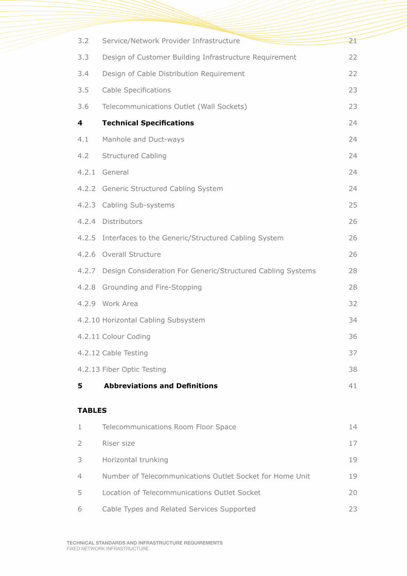
3.2 Service/Network Provider Infrastructure 21
3.3 Design of Customer Building Infrastructure Requirement 22
3.4 Design of Cable Distribution Requirement 22
3.5 Cable Specifications 23
3.6 Telecommunications Outlet (Wall Sockets) 23
4 TechnicalSpecifications 24
4.1 Manhole and Duct-ways 24
4.2 Structured Cabling 24
4.2.1 General 24
4.2.2 Generic Structured Cabling System 24
4.2.3 Cabling Sub-systems 25
4.2.4 Distributors 26
4.2.5 Interfaces to the Generic/Structured Cabling System 26
4.2.6 Overall Structure 26
4.2.7 Design Consideration For Generic/Structured Cabling Systems 28
4.2.8 Grounding and Fire-Stopping 28
4.2.9 Work Area 32
4.2.10 Horizontal Cabling Subsystem 34
4.2.11 Colour Coding 36
4.2.12 Cable Testing 37
4.2.13 Fiber Optic Testing 38
AbbreviationsandDefinitions5 41
TABLES
1 Telecommunications Room Floor Space 14
2 Riser size 17
3 Horizontal trunking 19
4 Number of Telecommunications Outlet Socket for Home Unit 19
5 Location of Telecommunications Outlet Socket 20
6 Cable Types and Related Services Supported 23
TECHNICAL STANDARDS AND INFRASTRUCTURE REQUIREMENTSFIXED NETWORK INFRASTRUCTURE
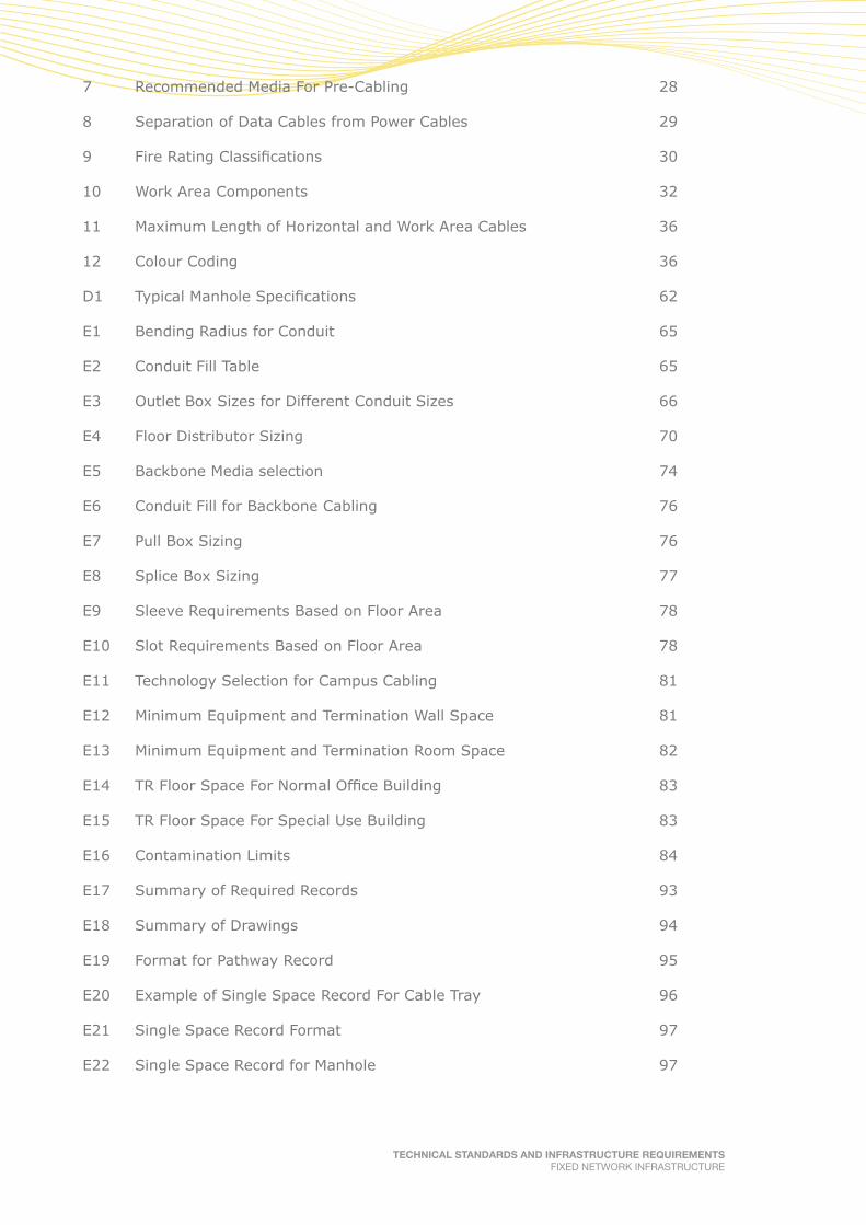
7 Recommended Media For Pre-Cabling 28
8 Separation of Data Cables from Power Cables 29
9 Fire Rating Classifications 30
10 Work Area Components 32
11 Maximum Length of Horizontal and Work Area Cables 36
12 Colour Coding 36
D1 Typical Manhole Specifications 62
E1 Bending Radius for Conduit 65
E2 Conduit Fill Table 65
E3 Outlet Box Sizes for Different Conduit Sizes 66
E4 Floor Distributor Sizing 70
E5 Backbone Media selection 74
E6 Conduit Fill for Backbone Cabling 76
E7 Pull Box Sizing 76
E8 Splice Box Sizing 77
E9 Sleeve Requirements Based on Floor Area 78
E10 Slot Requirements Based on Floor Area 78
E11 Technology Selection for Campus Cabling 81
E12 Minimum Equipment and Termination Wall Space 81
E13 Minimum Equipment and Termination Room Space 82
E14 TR Floor Space For Normal Office Building 83
E15 TR Floor Space For Special Use Building 83
E16 Contamination Limits 84
E17 Summary of Required Records 93
E18 Summary of Drawings 94
E19 Format for Pathway Record 95
E20 Example of Single Space Record For Cable Tray 96
E21 Single Space Record Format 97
E22 Single Space Record for Manhole 97

TECHNICAL STANDARDS AND INFRASTRUCTURE REQUIREMENTSFIXED NETWORK INFRASTRUCTURE
E23 Pathway Summary Report 98
E24 Pathway Content Report 98
E25 Space Summary Report 98
E26 Format for Cable Record 102
E27 Format for Termination Hardware Record 102
E28 Format for Termination Position Record 103
E29 Format for Splice Record 104
E30 Cable Report 104
E31 User Master Report 105
E32 End-to-End Circuit Report 105
E33 Cross Connect Report 105
FIGURES
1 Grounding System Termination 16
2 Modes of Access from Service / Network Provider to Customer 22
3 The Cabling Sub-System 25
4 Possible Interfaces at the Distributors and TO 26
5 Inter- Relationship of Functional Elements 27
6 Example of Generic / Structured Cabling System 27
7 Fire-stopping Concrete Barrier 31
8 Fire-stopping Wall Boxes 31
9 Fire-stopping Cable Trays 32
10 Configuration of TO 33
11 Pair Assignment for T568B 33
12 Maximum Cable Distance of Work Area 34
13 Horizontal Cable Distance for Copper Cables 35
14 Horizontal Cable Distance for Optical Fiber Cables 35
15 Illustration of Colour Coding 37
16 Permanent Link Testing Configuration 38
17 Fiber Optic Visual Check 39

TECHNICAL STANDARDS AND INFRASTRUCTURE REQUIREMENTSFIXED NETWORK INFRASTRUCTURE
A1 Insertion Loss Measurement 51
B1 Cable Entry into Building 52 – Typical Civil Infrastructure for Single Road Access
B2 Cable Entry into Building 53 – Typical Civil Infrastructure for Multiple Road Access
B3 Cable Entry into Building, Telecommunications Room on First Floor 54
B4 Telecommunications Equipment Room – Typical Layout Plan 55
B5 Telecommunications Room – Cross Section 55
B6 Telecommunications Room – Typical Cable Rack 56
B7 Cable Boundary for Multi-storey by either Building Owner or Network 57 Provider
B8 Equipment and Trunking Arrangements 58
B9 Telecommunication Riser Arrangements 59
C1 Typical Structured Cabling in Commercial Building 60
C2 Horizontal Floor Distribution – Typical Grid and Branch Layout System 61
D1 Typical Manhole Design 62
E1 Headroom above Cable Tray 67
E2 Hanging Pathways 68
E3 Typical Perimeter Raceway 69
E4 Direct Patching Method 72
E5 Indirect Patching Method 73
E6 Physical Topology For Backbone Topology 74
E7 Sleeve and Slot Designs 77
E8 Support Collar 79
E9 Campus Cabling Sub - System 80
E10 Maximum Campus Cabling Distance 81
E11 Distribution Frames Component Layout 87
E12 Airflow before Re-Arrangement 89
E13 Airflow after Re-Arrangement 90
E14 Example of Configured Rack 91
E15 Identifier / Record Concept 92

TECHNICAL STANDARDS AND INFRASTRUCTURE REQUIREMENTSFIXED NETWORK INFRASTRUCTURE
E16 Horizontal Cable Administration 99
E17 Backbone Cable Identifier 100
ANNEXES
A Fiber Optic Testing Procedure 50
B Recommended Building Infrastructure Design 52
C Recommended Cable Distribution Design 60
D Recommended Manhole Design 62
E Recommended Structured Cable Design, Installation and Testing 63

TECHNICAL STANDARDS AND INFRASTRUCTURE REQUIREMENTSFIXED NETWORK INFRASTRUCTURE 11
Committee representation
The Fixed Network Infrastructure Sub Work Group operates under the wing of the main Multimedia Network Infrastructure (MNI) Work Group which is supervised by the Malaysian Technical Standards Forum Bhd (MTSFB) authorized by Malaysian Communications and Multimedia Commission (SKMM). The TSIR- Fixed Network Infrastructure document was developed by various members whom are representatives from the following Broadcasters, Cabling manufacturer, Government Agencies, Manufacturer Associations and Professional Bodies, namely:
AMP Connectors Sdn Bhd
CableView Services Sdn Bhd (Mega TV)
Celcom (Malaysia) Berhad
Construction Industry Development Board Malaysia (CIDB)
Datacraft Malaysia Sdn Bhd
Dewan Bandaraya Kuala Lumpur
Diamond Components Sdn Bhd
DiGi Telecommunications Sdn Bhd
Fujikura Federal Cable
Institution of Engineers Malaysia
Jabatan Bomba Dan Penyelamat Malaysia
Jabatan Kerja Raya Malaysia
Leader Universal Optic
Malaysian National Computer Confederation
Maxis Communications Berhad
Measat Broadcast Network Systems Sdn Bhd
Natseven TV Sdn Bhd
Ortronics
SIRIM Berhad
Sistem Televisyen Malaysia Berhad (TV3)
Telekom Malaysia Berhad
Time dotCom Berhad
U Television Sdn Bhd (formerly known as MiTV Corporation Sdn Bhd)
Zettabits Technologies (M) Sdn Bhd


TECHNICAL STANDARDS AND INFRASTRUCTURE REQUIREMENTSFIXED NETWORK INFRASTRUCTURE 13
TECHNICAL STANDARDS AND INFRASTRUCTURE REQUIREMENTS Part 1: FIXED NETWORK INFRASTRUCTURE
1. Introduction
The Fixed Network Infrastructure forms a part of the Technical Standards and Infrastructure Requirements (TSIR) document which serves as guidelines and standards in support of the Uniform Building By-Laws (UBBL). This document was prepared with the common understanding and agreement among the Fixed Network Providers’ representatives in Malaysia. This sub-working group committee called Fixed Network Infrastructure is formed under the Multimedia Network Infrastructure (MNI) Working Group, approved by MTSFB.
In the context of meeting the needs of telecommunication (fixed network services) users, TSIR addresses the technical system and infrastructure requirements necessary for having the fixed network distribution system equipped in the building. This is important in view of Fixed Network Services which are used as a medium for delivery of Telephony and Multi Broadband Services to the public / customers.
1.1 Document Objective
As stated above, the Fixed Network Infrastructure in the TSIR document covers two primary objectives:
a) It outlines the infrastructure requirements (for the purpose of setting up a common and integrated fixed network distribution system) to consulting engineers, Developers, owners and other responsible parties for the provisions to be made available in the buildings.
b) It also provides the minimum technical specifications necessary for the Fixed Network Telephony and Multi broadband distribution system to function as required in buildings.
1.2 Document Scope
The Fixed Network Infrastructure covers the following focus areas:
a) System infrastructure requirement in building (condo/ apartment, low cost flats, single dwelling and office buildings).
b) Minimum installation guidelines and standards.
c) Minimum technical and performance specifications for the services (including test procedures).
1.3 Representation
The representatives in Fixed Network Infrastructure sub-workgroup are from various Telecommunication Operators namely, Telekom Malaysia Berhad, TIME, Maxis, DiGi, Consultants, MNCC and SIRIM as the national standards body.
TECHNICAL STANDARDS AND INFRASTRUCTURE REQUIREMENTSFIXED NETWORK INFRASTRUCTURE14
2. Building Requirements for Fixed Network Infrastructure
2.1 Outdoor Requirements
2.1.1 Manhole at Roadside
Manhole(s) on the road side outside the building / compound shall be provided by the building owner so that the Fixed Network Operator / Service Provider can connect their underground (manholes and ducts) network.
The Developer is strongly advised to consult the Fixed Network Operators on the appropriate selection of the location and size of manhole to be allocated.
2.1.2 Duct-Way into Building
Underground duct-ways are required to connect the manhole mentioned above to the Telecommunications Room inside the building. The number of duct-ways is dependent upon the size and types of building and number of users/ customer.
The Developer is strongly advised to consult the Fixed Network Operators on the appropriate selection of the number of duct-ways to be provided.
2.2 Telecommunications Room
2.2.1 Space Requirement
The Developer must dedicate a room with security lock to locate all fixed network equipment and cables, identified as the Telecommunications Room.
The floor area is required for Telecommunications Room inclusive of the subscriber distribution frame and termination equipment shall depend on the type and ultimate demand of the building. A minimum clear floor space of 750mm is essential in front of all accessible points of the equipment in order to provide adequate working space for installation, testing and maintenance service.
The Telecommunications Room shall be placed on the ground floor area and connected to the manhole and duct-way mentioned in section 2.1 and should be located free from perceptible vibration. Ducting, sewage pipes, air condition pipes etc. shall not pass through the Telecommunications Room. Refer to Table 1 for details.
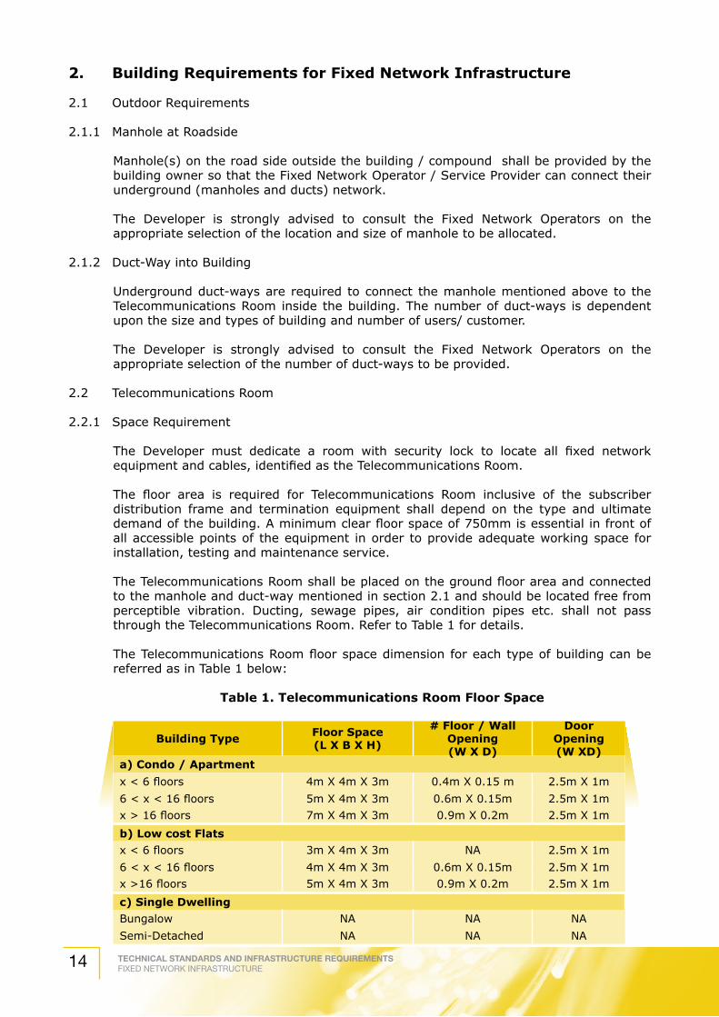
The Telecommunications Room floor space dimension for each type of building can be referred as in Table 1 below:
Table 1. Telecommunications Room Floor Space
Building Type Floor Space(L X B X H)
# Floor / Wall Opening(W X D)
DoorOpening(W XD)
a) Condo / Apartment
x < 6 floors 4m X 4m X 3m 0.4m X 0.15 m 2.5m X 1m
6 < x < 16 floors 5m X 4m X 3m 0.6m X 0.15m 2.5m X 1m
x > 16 floors 7m X 4m X 3m 0.9m X 0.2m 2.5m X 1m
b) Low cost Flats
x < 6 floors 3m X 4m X 3m NA 2.5m X 1m
6 < x < 16 floors 4m X 4m X 3m 0.6m X 0.15m 2.5m X 1m
x >16 floors 5m X 4m X 3m 0.9m X 0.2m 2.5m X 1m
c) Single Dwelling
Bungalow NA NA NA
Semi-Detached NA NA NA

TECHNICAL STANDARDS AND INFRASTRUCTURE REQUIREMENTSFIXED NETWORK INFRASTRUCTURE 15
Building Type Floor Space(L X B X H)
# Floor / Wall Opening(W X D)
DoorOpening(W XD)
Terrace Single Storey NA NA NA
Terrace Double Storey NA NA NA
Low cost NA NA NA
d)OfficeBuilding
x < 6,000m2 4m X 3m X 3m 0.7m X 0.15m 2.5m X 1m
6,000m2 < x < 20,000m2 4m X 4m X 3m 1.0m X 0.2m 2.5m X 1m
20,000m2 < x < 60,000m2 5m X 5m X 3m 1.1m X 0.2m 2.5m X 1m
x > 60,000m2 7m X 6m X 3m 1.1m X 0.2m 2.5m X 1m
e) Shop house
x < 6 storeyRequirement to be determined case by
case
Requirement to be determined case
by case
Requirement to be
determined case by case
f) Others
Industrial Lot
Requirement to be determined case by
case
Requirement to be determined case
by case
Requirement to be
determined case by case
Hotel
Schools
Hospital
Club house
NOTES:1. NA implies Not Applicable
2. # Two opening is required i.e. one serve the outdoor manhole duct-way access and the other serve the riser cable distribution.
2.2.2 Electrical Requirement
The Telecommunications Room shall be provided with electrical AC supply from the utility supplies at a nominal of 415 V, 3 phase, 4 wires, 50 Hz system or at a nominal voltage of 240V AC Single-Phase system with solidly earth system. The type of AC supply and rating will be dependent on the expected load.
The Telecommunications Room shall be equipped with a 20A TPN metal clad Distribution Box (DB) of 20A. The DB should be equipped with the following:
a) ELCB (Earth Leakage Circuit Breaker)
b) ARS (Automatic Restoration System); an auto re-closure device that works with the ELCB.
c) To normalize the power system for ensuring minimum system downtime and site attendance.
d) Surge protection system of 40KA and
e) 20-way MCB (Main Circuit Breaker) (buildings with 6 floors and above).
The electrical supply should be connected to the essential power generator if provided. An earth leakage circuit breaker shall be installed inside the room.
The Telecommunications Room shall be equipped with daylight type fluorescent lighting that can provide a minimum of 300 Lux luminance at floor level. The earthing system should have a resistance to earth of not greater than 10 ohm (Ref: BS6651 and
Table 1. Telecommunications Room Floor Space (continue)

TECHNICAL STANDARDS AND INFRASTRUCTURE REQUIREMENTSFIXED NETWORK INFRASTRUCTURE16
IEC60364-1), and be terminated on an earth bus bar inside the room. The main earth conductor should have a cross section of not less than 70 mm2 via the shortest routing. The earthing system shall be connected to the building main grounding. The grounding system termination is as Figure 1 below.
Figure 1. Grounding System Termination
2.2.3 Temperature/Ventilation
The Telecommunications Room shall be air-conditioned or equipped to maintain humidity and room temperature at 30% – 50% relative humidity and below 30 oC respectively under all conditions. The room shall be fitted with a ventilation fan system capable of 30 air change/min, activated when the room temperature rises above 35 ºC.
2.2.4 Accessibility
There should be no opening in the Telecommunications Room except for the door, the ventilation and cabling ducts. The door dimension shall be 1m x 2.5m. All windows if any must be shut and sealed along the frames to keep out water and dust and blind should be provided to avoid direct sunlight. Solid walls should be provided for heavy equipment mounting. The walls and ceiling should be of normal finishing or be painted with light-colored vinyl emulsion or gloss paint. Floor of the Telecommunications Room shall be of material that is easy to clean and not susceptible to accumulation of dust, flooring requirement is anti-static vinyl type mat and bonded to the earth bus bar. The room must be flood free. A 150 mm kerb across the doorway is required to prevent water from entering the room.
2.2.5 Security
The Telecommunications Room shall be locked at all times and only authorized personnel be allowed access. The key for this room shall be kept by the owner of the building or the building manager and made available to authorized personnel when required. No water tank, main water drainage pipes should be installed directly above the room. Developer should observe all relevant ordinance and regulation regarding the fire safety
Earth Window
70 mm2
1200 mm
1500 mmto1800 mm
70 mm2
Main Earth Terminal
To Earth ArrayFloor

TECHNICAL STANDARDS AND INFRASTRUCTURE REQUIREMENTSFIXED NETWORK INFRASTRUCTURE 17
requirements during the design of the Telecommunications Room, by having:
a) portable hand-operated fire extinguisher; and
b) emergency lighting connection to backup power supply.
Smoke detection device should be installed inside the Telecommunications Room and be connected to the central control of the building management office. The room should be fitted with a fire door as per “Jabatan Bomba dan Penyelamat Malaysia” approval.
2.2.6 Floor Loading
The Telecommunication Room shall be designed for a minimum distributed load of 500 kg/m2 and concentrated floor loading of 910 kg/m2.
2.2.7 Room Height
The clear ceiling height of Telecommunications Room shall not be less than 3 meter, so as to enable installation of equipment, cabinets and cabling.
2.3 Riser
2.3.1 Riser Requirements
To obtain maximum benefit from the distribution system, the riser duct should be placed centrally with respect to the distribution in which it is to serve. To facilitate the installation and maintenance of horizontal cables, the distance between the riser duct and the outlet point in the home unit should be kept as short as possible that is less than 30 meters. A 150 mm high kerb shall be provided across the doorway to prevent water from getting in. For low cost building the cable riser shall be sited in easily accessible area inside the building like staircase landing area.
The following services are not allowed to share this riser:
a) Water piping.
b) Fire fighting.
c) Building Electrical System.
d) Gas distribution.
e) Any other services that may cause moist, danger or any harmful effect on human life.
2.3.2 Riser Size / Working Space
The size of the riser shall be based on the type of building as in Table 2 below:
Table 2. Riser size
Building TypeRISER
Cable Trunking Floor Opening(W x D)
Closet Space(W x D)
a) Condo / Apartment
x < 6 floors 100mm x 75mm x 3 0.4m x 0.15m 0.9m x 0.6m
6 < x < 16 floors 150mm x 100mm x 3 0.6m x 0.15m 1.2m x 0.6m
x > 16 floors 150mm 100mm x 3 0.9m x 0.2m 1.5m x 0.8m

TECHNICAL STANDARDS AND INFRASTRUCTURE REQUIREMENTSFIXED NETWORK INFRASTRUCTURE18
Building TypeRISER
Cable Trunking Floor Opening(W x D)
Closet Space(W x D)
b) Low cost Flats
x < 6 floors 100mm x 75mm x 3 NA NA
6 < x < 16 floors 150mm x 100mm x 3 0.6m x 0.15m 1.2m x 0.6m
x > 16 floors 150mm x 100mm x 3 0.9m x 0.2m 1.5m x 0.8m
c) Single Dwelling
Bungalow NA NA NA
Semi-Detached NA NA NA
Terrace Single Storey NA NA NA
Terrace Double Storey NA NA NA
Low cost NA NA NA
d)OfficeBuilding
x < 6,000 m2 150mm x 100mm x 3 0.7m x 0.15m 1.2m x 0.9m
6,000m2 < x < 20,000 m2 150mm x 100mm x 3 1.0m x 0.2m 1.5m x 0.9m
20,000m2 < x < 60,000 m2 150mm x 100mm x 3 1.1m x 0.2m 1.8m x 1.2m
x > 60,000m2 150mm x 100mm x 3 1.1m x 0.2m 1.8m x 1.2m
e) Shop housex < 6 storey 100mm x 75mm x 3 NA NA
f) Others
Industrial Lot
Requirement to be determined case by case
Hotel
Schools
Hospital
Club house
2.3.3 Vertical closed cable trunking and the riser can be shared between Broadcast services, and other Telecommunications services. The arrangement of these cables in the riser shall be as follows:
a) from the left is for Radio Communication (Cellular Network) services;
b) the center is for Telecommunication (Fixed Network) services; and
c) from right side is for Broadcast services.
Closed trunking shall be used and solidly grounded to provide shielding between different services. The trunking shall be galvanized steel plate, epoxy powder coated against corrosion with a finishing of light blue paint.
The Fixed Network horizontal conduit / trunking shall be separated and dedicated to related services such as follows:-
a) Telephony Services.
b) Digital Leased Circuit Services.
c) Multimedia Broadband Services.
d) Local Area Network (LAN).
e) Extra Light Voltage (ELV) Services.
Sharing of services apart from those listed above is strictly prohibited.
Table 2. Riser size (continue)

TECHNICAL STANDARDS AND INFRASTRUCTURE REQUIREMENTSFIXED NETWORK INFRASTRUCTURE 19
The size of the horizontal trunking along the corridor shall be according to the number of cables as shown in Table 3.
Table 3. Horizontal Trunking
Number of Cables Size of Trunking on Floor(mm x mm)
Size of Trunking on Ceiling(mm x mm)
Less than 10 1 no. 100 x 25 1 no. 100 x 50
10 to 20 2 nos. 100 x 25 2 nos. 100 x 50
More than 20 NA Comply to 50 % space factor
The size of the horizontal drop cable into the individual unit shall be using at least a PVC conduit of 19 mm diameter. All conduits or cable enclosure need to be completely concealed and should not protrude so as to reduce the aesthetics either within or outside the customer premise.
2.3.4 Accessibility
Access to each riser will be necessary on each floor and should always be available from a corridor or other common area to avoid undue disturbance to occupants. The riser shall have a hinged and locked door on every floor and it is important that it be fire proof. The riser door key shall be kept by the building owner for safe custody.
2.3.5 Electrical Requirement
The riser shall be fitted with sufficient flourescent lighting to facilitate work and the word “TELECOMMUNICATIONS SERVICES” shall be displayed on the door of the riser closure. A minimum of 2 nos. of 13 Amp power sockets shall be provided at the alternate building floor in the riser to cater for the need of Fixed Network services distribution equipment. However if needs arise for larger blocks (i.e. more than 10 apartment units per floor), 2 nos. of 13 Amp switch socket outlets for every floor is recommended.
2.4 Home Unit
2.4.1 Telecommunications Outlet
The recommended number of outlets shall be based on the type of building as in Table 4.
Table 4. Number of Telecommunications Outlet Socket for Home Unit
Building Type Recommended Number of Socket
a) Condo / Apartment
x < 6 floors
6 < x < 16 floors 3 x Telephony / Broadband
x > 16 floors
b) Low cost Flats
x < 6 floors
6 < x < 16floors 2 x Telephony / Broadband
x > 16 floors
c) Single Dwelling
Bungalow 5 x Telephony / Broadband
Semi-Detached 3 x Telephony / Broadband
Terrace Single Storey 2 x Telephony / Broadband
Terrace Double Storey 3 x Telephony / Broadband
TECHNICAL STANDARDS AND INFRASTRUCTURE REQUIREMENTSFIXED NETWORK INFRASTRUCTURE20
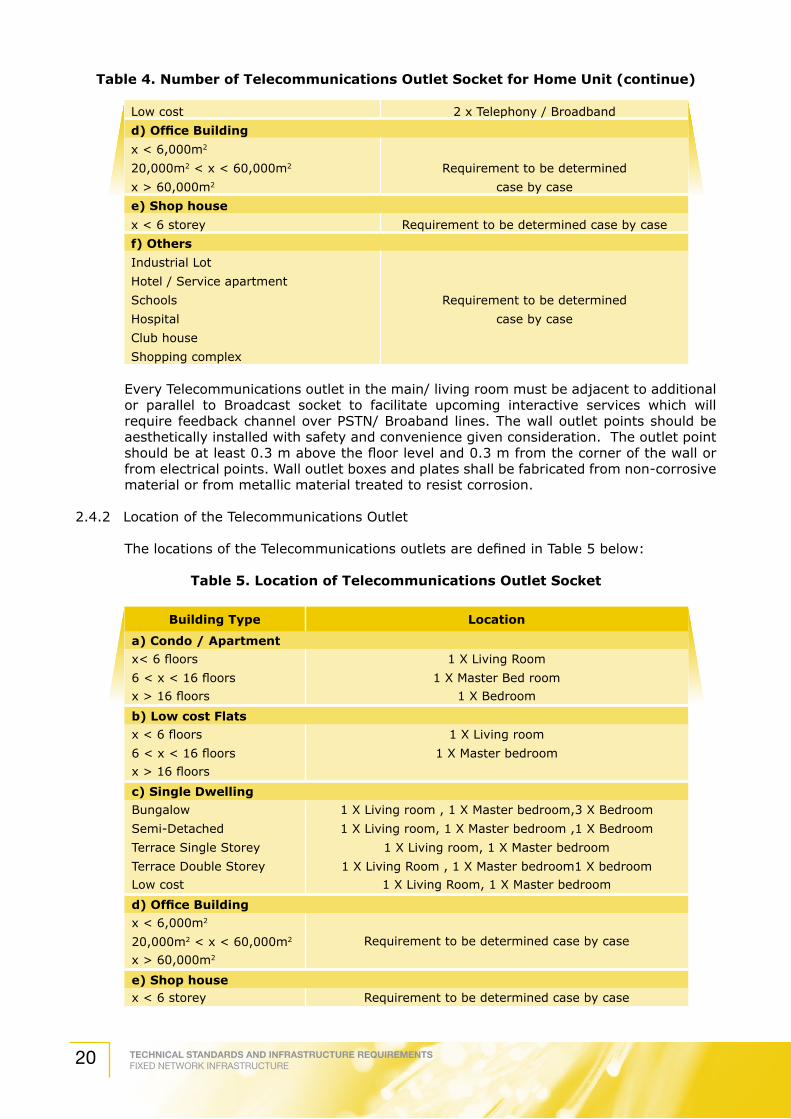
Low cost 2 x Telephony / Broadband
d)OfficeBuilding
x < 6,000m2
20,000m2 < x < 60,000m2 Requirement to be determined
x > 60,000m2 case by case
e) Shop house
x < 6 storey Requirement to be determined case by case
f) Others
Industrial Lot
Hotel / Service apartment
Schools Requirement to be determined
Hospital case by case
Club house
Shopping complex
Every Telecommunications outlet in the main/ living room must be adjacent to additional or parallel to Broadcast socket to facilitate upcoming interactive services which will require feedback channel over PSTN/ Broaband lines. The wall outlet points should be aesthetically installed with safety and convenience given consideration. The outlet point should be at least 0.3 m above the floor level and 0.3 m from the corner of the wall or from electrical points. Wall outlet boxes and plates shall be fabricated from non-corrosive material or from metallic material treated to resist corrosion.
2.4.2 Location of the Telecommunications Outlet
The locations of the Telecommunications outlets are defined in Table 5 below:
Table 5. Location of Telecommunications Outlet Socket
Building Type Location
a) Condo / Apartment
x< 6 floors 1 X Living Room
6 < x < 16 floors 1 X Master Bed room
x > 16 floors 1 X Bedroom
b) Low cost Flats
x < 6 floors 1 X Living room
6 < x < 16 floors 1 X Master bedroom
x > 16 floors
c) Single Dwelling
Bungalow 1 X Living room , 1 X Master bedroom,3 X Bedroom
Semi-Detached 1 X Living room, 1 X Master bedroom ,1 X Bedroom
Terrace Single Storey 1 X Living room, 1 X Master bedroom
Terrace Double Storey 1 X Living Room , 1 X Master bedroom1 X bedroom
Low cost 1 X Living Room, 1 X Master bedroom
d)OfficeBuilding
x < 6,000m2
Requirement to be determined case by case20,000m2 < x < 60,000m2
x > 60,000m2
e) Shop housex < 6 storey Requirement to be determined case by case
Table 4. Number of Telecommunications Outlet Socket for Home Unit (continue)

TECHNICAL STANDARDS AND INFRASTRUCTURE REQUIREMENTSFIXED NETWORK INFRASTRUCTURE 21
Building Type Location
f) Others
Industrial Lot
Requirement to be determined case by case
Hotel
Schools
Hospital
Club house
Shopping complex Requirement to be determined case by case
Developer should provide provision for additional wall socket in other location in the room, not already specified in Table 5 to meet the requirement of the occupant.
3. Technical Information
3.1 Service / Network Provider
The Service Provider is the entity that will provide the Fixed Network Services such as POTS (Plain Old Telephone Service) and ISDN (Integrated Switch Digital Network) and Broadband services etc. There can be more than one Service Provider giving service to the same customer.
The Service Provider can provide the above-mentioned services via their own network infrastructure or leasing from a Network Provider, as provided for in SKMM’s Guidelines On Implementation of Access to Network Elements (SKMM/G/04/05 – 28th September 2005)
3.2 Service / Network Provider Infrastructure
Figure 2 illustrates the overall configuration showing the various modes of providing fixed network services:
a) On copper cable from service / network provider premises to customer premises to provide POTS and ISDN services
b) ADSL (Asynchronous Digital Subscriber Line) riding on copper cable from service / network provider premises to customer premises to provide broadband services.
c) On fiber optic cable from service / network provider premises to customer premises with various optical terminal / multiplexer equipment (such as AG – Access Gateway, DSLAM – Digital Subscriber Line Access Multiplexer, RDSLAM – Remote DSLAM, MSAN – Multi-Services Access Node, FTTH – Fiber To The Home Etc.) To provide POTS, ISDN, broadband and other services.
Table 5. Location of Telecommunications Outlet Socket

TECHNICAL STANDARDS AND INFRASTRUCTURE REQUIREMENTSFIXED NETWORK INFRASTRUCTURE22
Figure 2. Modes of Access from Service / Network Provider to Customer
3.3 Design of Customer Building Infrastructure Requirement
Annex B illustrates the design of Building infrastructure required in providing fixed network services.
a) Service / network provider duct route (manholes and duct-ways) system will finally be connected to the customers building via the customers manhole and duct-ways.
b) The Telecommunications Room will house the service / network provider equipment and cable. The room size as per Table 1 of section 2.2.1.
c) The cables or terminations from the equipment will be connected to individual customer units via the riser (vertical distribution) and floor by floor (horizontal distribution).
3.4 Design of Cable Distribution Requirement
Annex C illustrates the design for cable distribution in buildings.
a) Cable (copper or fber optics) from the service / network provider will go via their manholes and duct-ways and finally to the customers building via the customer manhole and duct-ways.
b) Copper cables will be terminated onto the SDF (Subscriber Distribution Frame) in the Telecommunications Room.
c) Fiber cable will be terminated onto the FDF (Fiber Distribution Frame) in the Telecommunications Room.
d) Cables from the Telecommunications Room will be connected to the individual units via the vertical and horizontal distribution
Metro E
Business AccessLarge Enterprise
DSLAM
RDSLAM
FTTH(OLT)
FTTHsplitter
MSAN(COT) MSAN
(RT)
AG/MSAN
SERVICE / NETWORK PROVIDER PREMISES

TECHNICAL STANDARDS AND INFRASTRUCTURE REQUIREMENTSFIXED NETWORK INFRASTRUCTURE 23
3.5 Cable Specifications
The cable required to be installed will depend very much on the services required.
The services are categorized by the various signal / frequency bandwidth or data transmission speeds related to the services. The cable type that can support the related services are as per Table 6.
Table 6. Cable Types and Related Services Supported
Minimum Cable Type Bandwidth Application Limit TSIR
Cat 3(ISO/IEC 11801 Class C
TIA/EIA 568 B)
16 MHz For voice telephony & ADSL in building or
inter building
Minimum Requirement
Cat 5e(ISO/IEC 11801 Class D
TIA/ EIA 568 B)
>100 MHz For Data transmission up to 1GB/s
transmission rate
For distance up to 100m
Fiber Optic(Multi mode OM2/OM3 &
Single mode)
>200 MHz/kmDepends on light
source
For Data transmission up to 1GB/s
transmission rate
For distance beyond 100m
3.6 Telecommunications Outlet (Wall Sockets)
The 3-connector wall outlet (POTS, Ethernet and Fiber Optics) shall be suitable for all Voice Telephony and Ethernet Broadband services. They shall be suitable for flush mounted and fully shielded. Based on international standards and specifications, common terms for these sockets are:
a) RJ11 (POTS) socket.
b) RJ45 (Ethernet) socket.

TECHNICAL STANDARDS AND INFRASTRUCTURE REQUIREMENTSFIXED NETWORK INFRASTRUCTURE24
4. TechnicalSpecifications
4.1 Manhole and Duct-ways
The manholes and duct-ways specifications are as per Annex D.
4.2 Structured Cabling
4.2.1 General
This guideline defines Service provider’s requirements and specifications for generic / structured cabling for office buildings and it covers:
a) Planning, installation and administration of cabling systems.
b) Testing procedures.
c) Related pathways and spaces for office buildings.
This guideline is a living document and is in conformance with the ISO/IEC 11801, TIA/EIA 568-A, 569-A, 606 and 607, Electricity Regulations 1994 & Rules “Peraturan - Peraturan Elektrik 1994 & Kaedah-Kaedah Jabatan Bekalan Letrik” (as 20th August 1995). Cabling shall comply with other local codes and regulations.
4.2.2. Generic Structured Cabling System
4.2.2.1 Structure
Generic / structured cabling comprises of the following elements:
a) Telecommunications Outlet (TO)
b) Transition Point (TP) – optional
c) Multi User Telecommunications Outlet Assembly (MUTOA) – optional
d) Consolidation Point (CP) - optional
e) Horizontal cabling
f) Floor Distributor (FD)
g) Building Backbone Cabling
h) Building Distributor (BD)
i) Campus Backbone cabling
j) Campus Distributor (CD)
Details describing the above and their recommended specifications are in Annex E.

TECHNICAL STANDARDS AND INFRASTRUCTURE REQUIREMENTSFIXED NETWORK INFRASTRUCTURE 25
4.2.3 Cabling Sub-systems
4.2.3.1 General
The cabling sub-system comprises of campus backbone cabling, building backbone cabling and horizontal cabling. These sub-systems are connected together to form a generic structure as illustrated in Figure 3
NOTES: At each Distributor, direct or patched connections may be made to:1.equipment2.service presentation3.other cabling sub-systems
Figure 3. The Cabling Sub-System
These structure support different topologies, such as bus, star and ring topologies. In this guideline, star topology shall be used.
4.2.3.2 Work Area Cabling
Work area cabling connects the TO to the terminal equipment (TE).
The terminal equipment (TE) can be any of a number of devices including but not limited to telephones, data terminals and computers.
Each individual work area shall be served by a minimum of two TOs.
It is non-permanent and is application specific.
4.2.3.3 Horizontal Cabling
Horizontal cabling runs from distributors at each floor (FD) to the TO. It shall include the horizontal cables, termination at either end or cross-connects at the FD and the TO.
Horizontal cable should be continuous from the FD to the TO. However, one Transition Point or Consolidation Point is allowed between a FD and any TO. The transmission characteristics of the horizontal cabling shall be maintained.
If an open office environment is required, then, a Multi-user TO Assembly (MUTOA) or a Consolidation Point (CP) can be used.
4.2.3.4 Building Backbone Cabling
The building backbone cabling extends from the Telecommunications Rooms to the Floor Distributors (FD) at each floor.
It shall include the building backbone cables, termination of the building backbone cables at both the Floor Distributors and Telecommunications Rooms and mechanical terminations at both ends.
CD BD FD TO
TE
Generic Cabling Sub-system
CampusBackboneCabling
Sub-system
BuildingBackboneCabling
Sub-system
HorizontalCabling
Sub-system
Work AreaCabling
Sub-system
TP(optional)

TECHNICAL STANDARDS AND INFRASTRUCTURE REQUIREMENTSFIXED NETWORK INFRASTRUCTURE26
The building backbone shall not contain any TP and copper backbone shall not contain any splices.
4.2.3.5 Campus Backbone Cabling
The campus backbone cabling extends from the Telecommunications Room in one building to the Telecommunications Room that is usually positioned in a different building.
It shall include the campus backbone cable, mechanical termination at both ends and cross-connects at the Telecommunications Room.
4.2.4 Distributors
Distributors interface the three cabling sub-systems. There are three types of distributors, namely Floor Distributors (FD), Building Distributors (BD) and Campus Distributors (CD).
FD interfaces horizontal cables to building backbone cables.
BD interfaces horizontal cables to building backbone cables and building backbone cables to campus backbone cables.
CD interfaces campus backbone cables from one building to another building. Both of these distributors are usually placed in a Telecommunications Room.
4.2.5 Interfaces to the Generic / Structured Cabling System
Interfaces to the cabling system are located at the end of each sub-system.
Figure 4 illustrates possible interfaces at the distributors and TO.
Equipment Connector Interface to generic cabling
Figure 4. Possible Interfaces at the Distributors And TO
A distributor may have an interface to an external cable services and may use either direct connection (inter-connect) or indirect connection (cross-connect).
Connections to the public network for provision of public telecommunications services are made at the public network interface.
4.2.6 Overall Structure
Generic / structured cabling system is based on a star cabling topology arranged in a hierarchy. This structure provides a high degree of flexibility in accommodating a number of applications.
CD BD FD TO
TE
InterconnectCross-Connect
EQUIPMENTEQUIPMENTEQUIPMENT
TP(optional)

TECHNICAL STANDARDS AND INFRASTRUCTURE REQUIREMENTSFIXED NETWORK INFRASTRUCTURE 27
The number and type of cabling sub-systems that are included in a generic / structured cabling implementation shall depend on the geography and size of the campus or building.
Figure 5. Inter-Relationship of Functional Elements
In some applications, additional direct connections between FD and BD are desirable and allowed. Building backbones may also interconnect FD.
A combination of functions of multiple distributors is permitted. An example of generic / structured cabling system is illustrated in Figure 6. Cables are placed in appropriate pathways which may be installed in ducts, tunnels and cable trays, depending on the design of the system.
Figure 6. Example of Generic / Structured Cabling System
Campus BackboneCable
Building Backbone Cable
BD and CD has been Combined as a single Distributor
Horizontal Cable
CD
BD BD
FD
FD
FD
TOTO
TOTOTOTP
TP
Optional Cables
Optional Transition Cable
TO
TO
TO
TOTP FD
FD
FD
FD
FD
FD
FD
FD
FD
BD/CD
BD CDTP OPTIONAL
CAMPUS CABLING SUB-SYSTEM

TECHNICAL STANDARDS AND INFRASTRUCTURE REQUIREMENTSFIXED NETWORK INFRASTRUCTURE28
4.2.7 Design Consideration for Generic / Structured Cabling Systems
4.2.7.1 General
In designing a generic / structured cabling system, preliminary information such as design consideration is useful.
The areas covered by this section are:
a) Preferred cable types for pre-cabling and recommended use.
b) Decision criteria on possible locations of distributors.
With this preliminary information, one can proceed on to design and decide on the optimal cable technology for pre-cabling of generic / structured cabling system.
4.2.7.2 Preferred Cable Types for Pre-Cabling and Recommended Use
This section gives a guideline on the recommended use of media in a particular sub-system for pre-cabling as in Table 7. Distance limitation for each type as in Table 6.
Table 7. Recommended Media for Pre-Cabling
Sub-System Media Type Recommended Use
Horizontal
Balanced UTP Cables Voice and low to medium bandwidth data
Optical Fiber Medium to high bandwidth data
Building backbone
Balanced UTP Cables Voice and low to medium bandwidth data
Optical Fiber Medium to high bandwidth data
Campus Backbone
Balanced UTP Cables For voice applications-
Optical fiberData - by using optical fiber-ground potential differences and other sources of interference
may be overcome
NOTES:Under certain circumstances (for example high bandwidth application, environmental conditions, security concerns), installation of optical fiber in the horizontal cabling subsystem should be considered.
The table summarizes the preferred applications for different types of cabling sub-systems.
4.2.8. Grounding and Fire-stopping
4.2.8.1 Grounding
Bonding shall be according to applicable to the local codes. Horizontal cables shall be grounded in accordance to the latest edition of Electricity Regulations 1994 & Rules “Peraturan - Peraturan Elektrik 1994 & Kaedah-Kaedah Jabatan Bekalan Letrik” (as 20th August 1995).
All shields of cables should be bonded at each FD. Usually, the shields are bonded to the equipment racks, which in turn, bonded to building ground.

TECHNICAL STANDARDS AND INFRASTRUCTURE REQUIREMENTSFIXED NETWORK INFRASTRUCTURE 29
The bond shall be designed so that:
a) The path to ground shall be permanent and continuous. Each individual rack should be individually bonded, so that the continuity of the ground path is maintained.
b) The cable shields provide a continuous ground path to all parts of cabling system that are interconnected by it.
The bonding is to ensure that voltages induced into cabling are directed into building ground and do not interfere with the transmitted signals.
All grounding electrodes of different systems in the building shall be bonded together to reduce the impact of differences in ground potential.
The building grounding systems should conform to the grounding potential limits of 1Vr.m.s. and a low resistance between any two grounds on the network. If the 1 Vr.m.s. could not be complied, optical fiber cabling should be used instead of twisted pair to eliminate the risk of high ground currents.
Metallic conduits used to reside ground conductors should be bonded to the ground conductor at both ends.
The bonding conductor shall be insulated and copper. The minimum conductor size shall be 6 AWG (16mm2) and of maximum size 3/0 AWG (95mm2). Each conductor shall be marked with green colour. Each bonding conductor shall be labelled with non-metallic labels as close to the point of termination as possible.
The protection and grounding of telecommunication equipment from the equipment to the master ground bar shall be the responsibility of the equipment provider.
4.2.8.2 Power Separation
Close proximity of data cables, electrical cables and other communications media may result in high EMI level.
The separation of communications and power cables shall be as in Table 8.
Table 8. Separation of Data Cables from Power Cables
Voltage Of Power Cables Separation Distance< 650 V Min 50 mm> 650 V Min 300 mm
Extra insulation with appropriate separation distance shall be provided at places where data and power cables cross.
Where data cables are routed specifically through ceiling cavities, the runs shall not be parallel with flourescent light fittings. It shall cross the fittings at right angles wherever possible.
4.2.8.3 Fire-stopping
4.2.8.3.1 Installer’s Responsibility
The installer shall be responsible for the sealing of openings between floors, through rated fire and smoke walls, existing or created by the installer for cable to pass through as per “Jabatan Bomba dan Penyelamat” requirements.

TECHNICAL STANDARDS AND INFRASTRUCTURE REQUIREMENTSFIXED NETWORK INFRASTRUCTURE30
The installer shall bear the responsibility of creating such openings that are necessary for cable passage between locations as shown on the drawings.
Any openings created by or for the installer and left unused shall also be sealed.
4.2.8.3.2 Fire-stopping methods
Fire-stopping is used to contain and prevent the spread of fire through architecturally designed fire barriers.
Fire-stopping materials are rated by test (ASTM E 814, UL 1479). The fire-rating classification shall be as follows:
Table9.FireRatingClassifications
Classification Characteristics
F
Ability to withstand the spread of fire through the firestop or auto •ignition on the side opposite the fire.
Ability to contain water stream from a fire hose without breach or •dislodging
T
Meets or exceeds the F rating •
Limiting temperature rise on the unexposed surface to no more than •180 oC (325 oF)
They are two Fire-stopping methods, namely mechanical and non-mechanical.
a) Mechanical: involves factory manufactured elastomeric material designed to fit in and/or around the cables or conduit.
Non-mechanical: involves a material that is capable of fitting around and or in b) irregular cables and pipes or openings.
Non-mechanical systems are widely used compared to mechanical system due to its practicality. Non-mechanical systems include caulk, intumescent wraps, pillows, cementitious compounds, foam and putties.
4.2.8.3.3 Installation Guidelines
a) Fire-stopping through a Concrete Barrier
When fire-stopping through a concrete barrier, fill the opening with fire resistant packing material to within the manufacturer specified distance from the edge of the opening.
Fill the remainder of the opening with fire-stop material. (Refer Figure 7 for illustration).
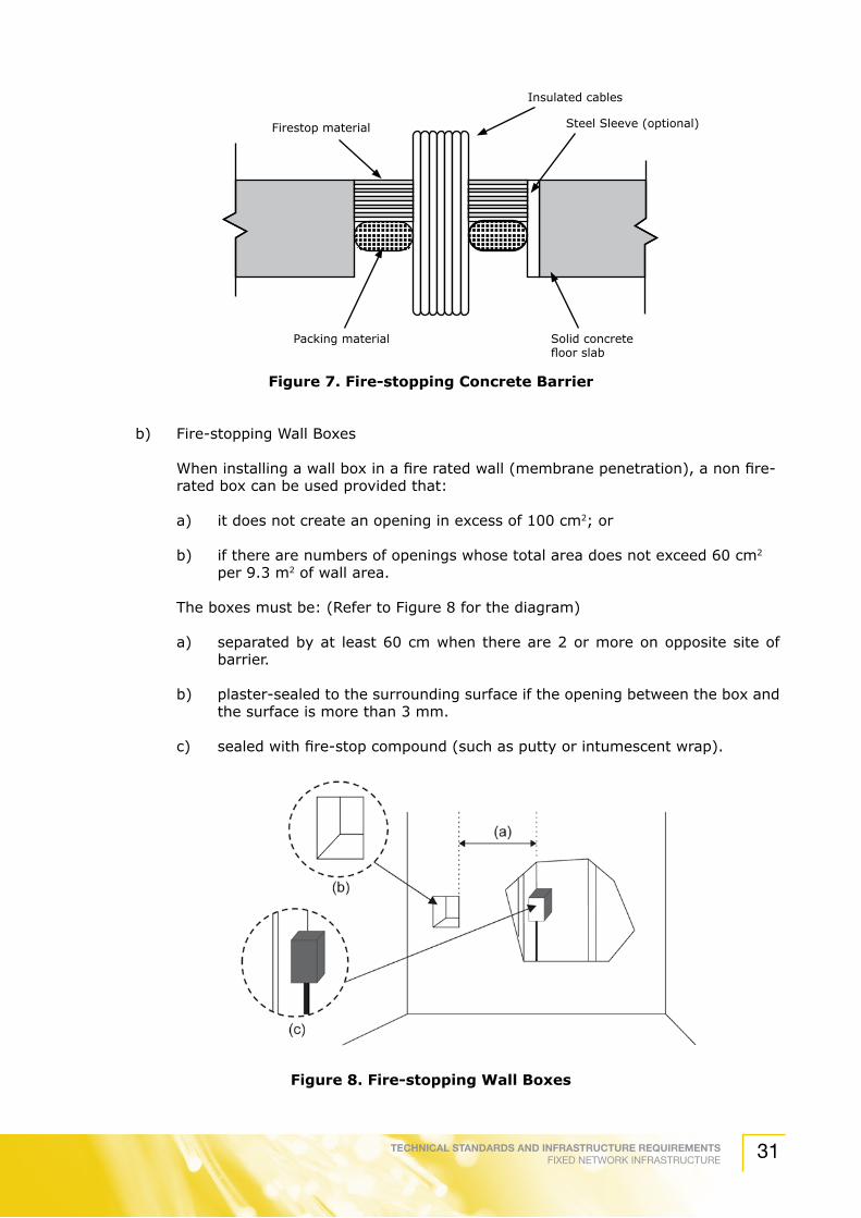
TECHNICAL STANDARDS AND INFRASTRUCTURE REQUIREMENTSFIXED NETWORK INFRASTRUCTURE 31
Figure 7. Fire-stopping Concrete Barrier
b) Fire-stopping Wall Boxes
When installing a wall box in a fire rated wall (membrane penetration), a non fire-rated box can be used provided that:
a) it does not create an opening in excess of 100 cm2; or
b) if there are numbers of openings whose total area does not exceed 60 cm2 per 9.3 m2 of wall area.
The boxes must be: (Refer to Figure 8 for the diagram)
a) separated by at least 60 cm when there are 2 or more on opposite site of barrier.
b) plaster-sealed to the surrounding surface if the opening between the box and the surface is more than 3 mm.
c) sealed with fire-stop compound (such as putty or intumescent wrap).
Figure 8. Fire-stopping Wall Boxes
Firestop material
Insulated cables
Steel Sleeve (optional)
Solid concrete floor slab
Packing material

TECHNICAL STANDARDS AND INFRASTRUCTURE REQUIREMENTSFIXED NETWORK INFRASTRUCTURE32
c) Fire-stopping Cable Trays
For cable trays, intumescent wrap materials are commonly used since they are flexible at room temperature and when exposed to high temperatures, they swell and harden to fill the openings.
Place the wrap on each side of the breached wall, around the tray and cables, fillings any large openings between the cables and cable trays.
Place additional strips around the opening to ensure proper sealing in event of fire.
Figure 9. Fire-Stopping Cable Trays
4.2.9 Work Area
4.2.9.1 General
The work area components extend from the telecommunications outlet (TO) to the application equipment. It shall be designed in a relatively simple way to allow easy management of moves, add and changes.
The work area components are:
Table 10. Work Area Components
Application equipment Computers, data terminals, telephones
Patch cables Modular cords, PC adapter cables, Fiber jumpers
Adapters Baluns
4.2.9.2 Telecommunications Outlet
TOs are located on the wall, depending on the design of the building. TOs shall be installed in readily accessible locations throughout the work area.
The minimum number of telecommunications outlet (TO) shall be two.

TECHNICAL STANDARDS AND INFRASTRUCTURE REQUIREMENTSFIXED NETWORK INFRASTRUCTURE 33
The two TOs in a work area shall be configured as follows:
a) One Telecommunication Outlet shall be supported by 100 Ω balanced cable category 5 or higher using TIA/EIA 568-A T568B wiring pattern outlet. (Category 5e minimum is recommended)
b) A second telecommunications outlet shall be supported by either a 100 Ω balanced cable of category 5 or higher or an optical Fiber cable.
Figure 10 and Figure 11 indicate the TO configuration and the pair assignment for 8 position modular jack connecting hardware using T568B wiring pattern respectively.
Figure10.ConfigurationofTO
Figure 11. Pair Assignment for T568B
The designer shall have the final say on the number of TOs provided that the minimum number of TO rule is not violated. A high density of TO will enhance the flexibility of the cabling to cater for future changes.
If a TO is supported by balanced cable, 4 pairs shall be provided at each TO with all pairs being terminated. TO shall be marked with a permanent label that is visible to each user. The changes shall be recorded.
Devices such as baluns and impedance matching adapters shall be connected externally (if being used).
100Ω balanced cable of category 5e or higher or 62.5/125 µm or 50/125 µm optical fiber cable
100Ω UTP 4 pair category 5e or higher (T568B wiring)
TECHNICAL STANDARDS AND INFRASTRUCTURE REQUIREMENTSFIXED NETWORK INFRASTRUCTURE34
Horizontal optical Fibers at the work area outlet shall be terminated to a duplex SC optical Fiber connector (SC-D). Other connector styles, including those of a small form factor (e.g. MT-RJ) may also be considered.
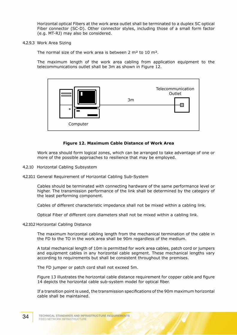
4.2.9.3 Work Area Sizing
The normal size of the work area is between 2 m² to 10 m².
The maximum length of the work area cabling from application equipment to the telecommunications outlet shall be 3m as shown in Figure 12.
Figure 12. Maximum Cable Distance of Work Area
Work area should form logical zones, which can be arranged to take advantage of one or more of the possible approaches to resilience that may be employed.
4.2.10 Horizontal Cabling Subsystem
4.2.10.1 General Requirement of Horizontal Cabling Sub-System
Cables should be terminated with connecting hardware of the same performance level or higher. The transmission performance of the link shall be determined by the category of the least performing component.
Cables of different characteristic impedance shall not be mixed within a cabling link.
Optical Fiber of different core diameters shall not be mixed within a cabling link.
4.2.10.2 Horizontal Cabling Distance
The maximum horizontal cabling length from the mechanical termination of the cable in the FD to the TO in the work area shall be 90m regardless of the medium.
A total mechanical length of 10m is permitted for work area cables, patch cord or jumpers and equipment cables in any horizontal cable segment. These mechanical lengths vary according to requirements but shall be consistent throughout the premises.
The FD jumper or patch cord shall not exceed 5m.
Figure 13 illustrates the horizontal cable distance requirement for copper cable and figure 14 depicts the horizontal cable sub-system model for optical fiber.
If a transition point is used, the transmission specifications of the 90m maximum horizontal cable shall be maintained.
3m
TelecommunicationOutlet
Computer

TECHNICAL STANDARDS AND INFRASTRUCTURE REQUIREMENTSFIXED NETWORK INFRASTRUCTURE 35
The combined electrical length (with reference to attenuation and NEXT) shall be 7.5m for equipment and work area cables.
Figure 13. Horizontal Cable Distance for Copper Cables
Figure 14. Horizontal Cable Distance for Optical Fiber Cables
4.2.10.3 Preferred Cable Types
The preferred cables for horizontal cabling sub-system are as follows:
a) 100 Ω balanced cable.
b) 50/125 µm multi-mode optical fiber.
c) 62.5/125 µm multi-mode optical fiber.
4.2.10.4 Multi User Telecommunications Outlet Assembly (MUTOA)
The MUTOA performs like a telecommunications outlet. However, it serves up to a maximum of 12 work areas.
The MUTOA shall be located centrally to serve a work group. Patch cords are installed at the MUTOA, through furniture pathways directly to the terminal equipment.
The MUTOA shall be located in an accessible area and not in ceiling or floor spaces.
The MUTOA shall be located in a permanent building structure or on furniture that is permanently fixed to the building structure.
E c c c
5m90m
Equipment Cable
PatchCable
Work AreaCable
Channel Specification
E - equipment in FDc - connection
Permanent Specification
TO
FD
E - equipment in FDc - connections - splice
90m
Channel Specification
Permanent Specification
FD
E c cs s
TECHNICAL STANDARDS AND INFRASTRUCTURE REQUIREMENTSFIXED NETWORK INFRASTRUCTURE36
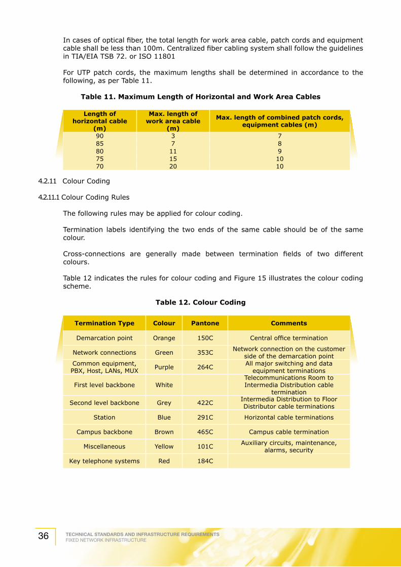
In cases of optical fiber, the total length for work area cable, patch cords and equipment cable shall be less than 100m. Centralized fiber cabling system shall follow the guidelines in TIA/EIA TSB 72. or ISO 11801
For UTP patch cords, the maximum lengths shall be determined in accordance to the following, as per Table 11.
Table 11. Maximum Length of Horizontal and Work Area Cables
Length of horizontal cable
(m)
Max. length of work area cable
(m)
Max. length of combined patch cords, equipment cables (m)
90 3 785 7 880 11 975 15 1070 20 10
4.2.11 Colour Coding 4.2.11.1 Colour Coding Rules
The following rules may be applied for colour coding.
Termination labels identifying the two ends of the same cable should be of the same colour.
Cross-connections are generally made between termination fields of two different colours.
Table 12 indicates the rules for colour coding and Figure 15 illustrates the colour coding scheme.
Table 12. Colour Coding
Termination Type Colour Pantone Comments
Demarcation point Orange 150C Central office termination
Network connections Green 353C Network connection on the customer side of the demarcation point
Common equipment, PBX, Host, LANs, MUX Purple 264C All major switching and data
equipment terminations
First level backbone WhiteTelecommunications Room to Intermedia Distribution cable
termination
Second level backbone Grey 422C Intermedia Distribution to Floor Distributor cable terminations
Station Blue 291C Horizontal cable terminations
Campus backbone Brown 465C Campus cable termination
Miscellaneous Yellow 101C Auxiliary circuits, maintenance, alarms, security
Key telephone systems Red 184C

TECHNICAL STANDARDS AND INFRASTRUCTURE REQUIREMENTSFIXED NETWORK INFRASTRUCTURE 37
Figure 15. Illustration of Colour Coding
4.2.11.2 Differentiation of Termination Field by Performance Category If the cables used are of different performance classes, their termination should indicate the difference, by either using enhanced colour coding, or suitable marking.
Alternatively, the cables may be marked with the category of the terminating cable.
4.2.12 Cable Testing 4.2.12.1 UTP Testing – Test Equipment
The test equipment for system certification should comply with Level IIE-Test Equipment. Level III Test Equipment is recommended.
The test equipment shall be initialized before use.
BLUE
BLUE PURPLE BROWN BROWN
BLUE GREEN
ORANGE
ID
FDBD
TR
TR
ENTRANCE FACILITYDemarcation
Point
To CentralOffice
BLUE
WHITE
WHITE
WHITE
GREY GREY
YELLOW
Horizontal Cabling
LEGEND
Telecommunication RoomIntermediate DistributorFloor DistributorTelecommunications MediaTelecommunications OutletCross Connect
TRIDFD
Second Level Backbone
First Level Backbone
TECHNICAL STANDARDS AND INFRASTRUCTURE REQUIREMENTSFIXED NETWORK INFRASTRUCTURE38
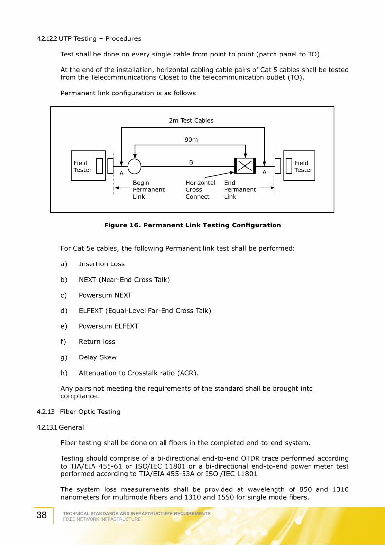
4.2.12.2 UTP Testing – Procedures Test shall be done on every single cable from point to point (patch panel to TO).
At the end of the installation, horizontal cabling cable pairs of Cat 5 cables shall be tested from the Telecommunications Closet to the telecommunication outlet (TO).
Permanent link configuration is as follows
Figure16.PermanentLinkTestingConfiguration
For Cat 5e cables, the following Permanent link test shall be performed:
a) Insertion Loss
b) NEXT (Near-End Cross Talk)
c) Powersum NEXT
d) ELFEXT (Equal-Level Far-End Cross Talk)
e) Powersum ELFEXT
f) Return loss
g) Delay Skew
h) Attenuation to Crosstalk ratio (ACR).
Any pairs not meeting the requirements of the standard shall be brought into compliance.
4.2.13 Fiber Optic Testing
4.2.13.1 General
Fiber testing shall be done on all fibers in the completed end-to-end system.
Testing should comprise of a bi-directional end-to-end OTDR trace performed according to TIA/EIA 455-61 or ISO/IEC 11801 or a bi-directional end-to-end power meter test performed according to TIA/EIA 455-53A or ISO /IEC 11801
The system loss measurements shall be provided at wavelength of 850 and 1310 nanometers for multimode fibers and 1310 and 1550 for single mode fibers.
2m Test Cables
FieldTester
BeginPermanentLink
EndPermanentLink
HorizontalCrossConnect
FieldTester
90m
A
B
A

TECHNICAL STANDARDS AND INFRASTRUCTURE REQUIREMENTSFIXED NETWORK INFRASTRUCTURE 39
Each link that does not conform to the standard requirement shall be brought into compliance.
4.2.13.2 Pre-Installation Testing
All fiber optic cables should be tested before the installation of the cable.
4.2.13.3 Running cable
a) Obtain a complete test data from the cable manufacturer, including attenuation, bandwidth and geometry of the fiber and cable construction details.
b) Check each fiber for continuity. This can be done by a simple light check if all certified data is in order. This is illustrated in Figure 17.
Figure 17. Fiber Optic Visual Check
c) Check the beginning and ending length markers for appropriate cable lengths.
4.2.13.4 Pre-Terminated Patch Cords
a) Obtain the test data from the manufacturer regarding the insertion loss testing.
b) Each connector should be inspected with an inspection microscope of at least 100 times enlargement. The fiber faces should be cleaned from chips and scratches.
c) Visually check the connector ferrules and make sure that they are free of epoxy or other contaminants. Check the moving parts of connector for free play.
d) All connectors shall be covered with dust cap.
4.2.13.5 Post-Installation Testing
4.2.13.5.1 Backbone Cables
a) Check all terminated fibers for optical loss at the appropriate wavelength (refer to Appendix A for fiber optic testing procedure)
b) Compare actual loss with the design loss. The calculation of optical loss is as follows:
(Allowable cable loss per km) (km of Fiber in link) + (0.5 dB) (Number of connectors) = Maximum allowable loss
A mated connector to connector interface is defined as single connectors.
Required goodcleaves
Flashlight
Fiber under test
NOTE:Do not look at fiber unless absolutely certain that no LASER or LED light is being trasmitted

TECHNICAL STANDARDS AND INFRASTRUCTURE REQUIREMENTSFIXED NETWORK INFRASTRUCTURE40
Check all the un-terminated fibers for continuity. If a discontinuity or excessive loss is located, correct the problem.
If the system includes runs of cables over 400m or 500m, get OTDR traces on the installed fibers. This is crucial should there be any problems in the link in the future.
4.2.13.5.2 Patch Cords
Check the patch cords as outlined in Annex E.
If acceptable, the patch cords need only be cleaned with a wipe of reagent-grade alcohol before installation.

TECHNICAL STANDARDS AND INFRASTRUCTURE REQUIREMENTSFIXED NETWORK INFRASTRUCTURE 41
5. AbbreviationsandDefinitions
For the purposes of this TSIR, the followings abbreviations and definitions apply.
Ablative : Developing a hard char that resists the spread of fire.
Access Floor : A system consisting of completely removable and interchangeable floor panels that are supported on adjustable pedestals or stringers to allow access to the area beneath.
Administration : Method for labeling, identification, documentation and usage needed to implement moves, add and changes of the telecommunication infrastructure.
Application : A system, with its associated transmission method which is supported by telecommunications cabling
Approval Authority : It is embodied in the CMA, SDBA, UBBL and TCPA that approval from the State Authority or Local authority or any other authority is a must before any development or construction activities can be carried out. In approving a development or building plan, the State Authority or local authority must satisfy all requirements pertaining to essential services which should in accordance with the proposal above include public utility services in line with the CMA 1998.
Architectural structures
Walls, floors, floor ceilings and roof that are load bearing
Attenuation Signal loss in a transmission medium or component expressed in dB.
The attenuation for 100m length of cable where the cable impedance is matched to the impedance of the test equipment, is defined as:
A = (100/ L)x 10 log10 (p1/p2)
Where A = attenuation constant.
p1 = input power where the load impedance is the source impedance.
p2 = output power where the load impedance is the test specimen impedance.
L = length of test specimen in meters.
Backbone : A facility (e.g. pathway, cable or conductors) between Telecommunications Closets, or Floor Distributor terminals, entrance facilities and the equipment rooms within or between the buildings.
Backbone Bonding Conductor
: A metal conductor that is a copper conductor extending from the telecommunications main grounding busbar to the furthest floor telecommunication grounding busbar
Balanced Cable : A cable consisting of one or more metallic symmetric cable elements (twisted pair or quads).
Barrier : Architectural structures and assemblies.

TECHNICAL STANDARDS AND INFRASTRUCTURE REQUIREMENTSFIXED NETWORK INFRASTRUCTURE42
BBS : Broadband Broadcast SysytemA network of coaxial cables and components in the frequency range of 5 MHz – 2150 MHz. It receives broadcasting signals from a common antenna/dish or system of antennas, centrally integrates and distributes the signal and to all outlets within the building.
BER : Bit Error RateIn a digital transmission, BER is the percentage of bits with errors divided by the total number of bits that have been transmitted, received or processed over a given time period. The rate is typically expressed as 10 to the negative power.
Block : A device used to connect one group of wires to another. Each wire can be connected to several other wires in a bus/ common arrangement
Bonding : The permanent joining of metallic parts to form an electrically conductive path that will assure electrical continuity and the capacity to conduct safely any current likely to be imposed.
Broadcast Head-end Room
: A dedicated secured room to locate all necessary receiving and processing equipment and components for the Broadband Broadcast System
Building : Shall have the same meaning provided for the National Land Code 1965, and shall mean to include any structure erected on land.
Building Backbone Cable
: A cable that connects the building distributor to a Floor Distributor. Building backbone cables may also interconnect Floor Distributors in the same building.
Building core : A three-dimensional space permeating one or more floors of the building and used for extension and distribution of utility services throughout the building.
Building Entrance Facility
: A facility that provides all necessary mechanical and electrical services that complies with all relevant regulations, for the entry of telecommunications cables into a building.
Building module : The standard selected as the dimensional co-ordination of the design of the building (such as a multiple of 100 mm).
Building owner : The actual proprietor of a building, or its agents or its authorized personnel.
Buried cable : A cable installed under the surface of the ground in such as manner that it cannot be removed without disturbing the soil.
Cabinet : A container that may enclose connection devices, terminations, apparatus, cabling and equipment.
Cable : An assembly of one or more cable units of the same type and category in an overall sheath. It may include overall shield.
Cable sheath : A covering over the conductor assembly that may include one or more metallic member, strength members or jacket.
Cable Unit : A single assembly of one or more cable elements of the same type or category. The cable unit may have a shield.
Cabling : A system of telecommunications cables, cords and connecting hardware that can support the connection of information technology equipment.
Campus : A premise containing one or more buildings.

TECHNICAL STANDARDS AND INFRASTRUCTURE REQUIREMENTSFIXED NETWORK INFRASTRUCTURE 43
Campus Backbone Cable
: A cable that connects the campus distributor to the building distributors. Campus backbone cables may also connect building distributors directly.
Campus Distributor : The distributor from which the campus backbone cabling emanates.
Campus Style Property
: A property with single document of title issued to a single proprietor of any land which parcel of land is not sub-divided.
Ceiling Distribution System
: A distribution system that utilizes the space between a suspended or false ceiling and the structural surface above.
Cell : A single raceway of a cellular under-floor duct system.
Cellular floor : A floor distribution method in which cables pass through floor cells, constructed steel or concrete to provide a ready made raceway for distribution of power and telecommunications cables.
Cellular Network : A mobile communications network system.
Cementitious firestop : A fire-stopping material that is mixed with water, similar in appearance to mortar.
Channel : End-to-end transmission path connecting any two piece of application specific equipment. Equipment and work area cables are included in the channel.
Characteristic Impedance
: At a given frequency, the characteristic impedance, Zc is defined as the input impedance of a homogeneous line of infinite length. Z~ is the asymptotic value the characteristic impedance approaches at high frequencies.
Civil infrastructure : Basic communications infrastructure installation needed for the establishment of fixed network communications network services such as pits, ducts, manholes and etc. but does not include a line.
CMA : Communication and Multimedia Act (1998)
CNR : Carrier-to-noise ratioThe ratio of the level of the carrier to that of the noise in the desired frequency band, expressed in dB.
Column : Connect one group of Fibers to another. A number of columns are grouped within a Fiber panel
Commercial Building : A building or portion thereof, which is intended for office use.
Concrete fill : A minimal depth concrete pour to encase single level underfloor duct.
Conduit : A raceway or circular cross-section of the type permitted under the appropriate electrical code.
Consolidation Point : An interconnection between horizontal cable extending from building pathways and cable extending into pathways to the work area telecommunication/connector.
Cross connect : A facility enabling the termination of cable elements and their connection, primarily by means of patch cords or jumpers
Cross over : The junction unit at the point of intersection of two cable trays, raceways, or conduit on different planes.

TECHNICAL STANDARDS AND INFRASTRUCTURE REQUIREMENTSFIXED NETWORK INFRASTRUCTURE44
dB(decibel) : A unit of measurement which expresses changes in signal power levels along a logarithmic scale. 3 dB represents a multiplication factor of 2; 10 dB a factor of 10; 20 dB a factor of 100; 30 dB a factor of 1000; etc.
Developer : Any person, body of person, company, firm or society (by whatever name described), who or which engages in or carries or undertakes or causes to be undertaking housing development.
Distributor : The term used for the functions of a collection of components (e.g. : patch panels, patch cords) used to connect cables.
Duct : An enclosed raceway for wires or cables usually used in soil or concrete an enclosure in which air is moved.
Entrance facility : An entrance to a building for both public and private network services cables including the entrance point at the building wall and continuing to the entrance room or space.
Entrance point : The point of emergence of telecommunication conductors through an exterior wall, a concrete floor slab or from a rigid metal conduit or intermediate metal conduit.
Entrance room or space
: A space in which the joining of inter or intra-building telecommunications backbone facilities takes place.
Equipment cables : A cable connecting equipment to a distributor.
Equipment room : A room dedicated to housing distributors and application specific equipment.
Fiber panel : Collection of fiber columns.
Fire-stopping : The process of installing specialty materials into penetrations in fire-rated to re-establish the integrity of the barrier.
Floor Distributor : The distributor is used for generic / structured cabling in the commercial building. It is to connect between the horizontal and other cabling sub-systems or equipment.
Frame : Horizontal collection of blocks.
Frequency : The number of times in which an alternating current goes through a complete cycle of 360 degrees in one second of time.
Gain : The amplification factor for communications devices expressed in dB. For antennas, gain is expressed in dB, decibels referenced to an isotropic reference antenna.
Generic Structured Cabling
: A structured communication cabling system, capable of supporting a wide range of applications. Generic cabling can be installed without prior knowledge of the required applications. Application specific hardware is not a part of the generic cabling.
Gbps : The prefix Giga means billion, and bps – bits per second is the speed of data transmission.
GHz : The prefix Giga means billion, and Hertz means cycles per second. Signals in the GHz range are often called microwaves.
Ground : A conducting connection, whether intentional or accidental, between an electrical circuit or equipment and earth, or to some conducting body that serves in place of earth.

TECHNICAL STANDARDS AND INFRASTRUCTURE REQUIREMENTSFIXED NETWORK INFRASTRUCTURE 45
Grounding electrode : A conductor, usually a rod, pipe or plate, in direct contact with the earth for the purpose of providing a low impedance connection to earth.
Handhole : A structure similar to a small maintenance hole in which it is expected that a person cannot enter to perform work.
Header duct : A raceway of rectangular cross-section placed within the floor to tie distribution ducts or cells to the Telecommunications Closet.
Horizontal cabling : Cable connecting the Floor Distributor to the telecommunications outlets.
Home runs : A pathway or cable between two locations without a point of access in between.
Housing Development : Develop or construct or cause to be constructed in any manner more than 4 units of housing accommodation and shop house in, on, over or under any land with the view of selling the same.
Hybrid cable : An assembly of two or more different types of cable units, cable categories covered by an overall sheath. It may be covered by an overall shield.
IEC : International Electrotechnical Commission.An organization that sets international electrical and electronics standards.
Individual work area : The minimum building space which could be reserve for an occupant.
Infrastructure : Any telecommunications plant and shall include post, ducts, manholes, relay, rack, cable racks, cable ladders, terminal frames, backboards, concrete slabs, riser passage, risers and the like, but does not include a line.
Insertion Loss The decrease in transmitted signal power resulting from the insertion of a device in a transmission line or optical fiber. It is usually expressed relative to the signal power delivered to that same part before insertion. Insertion loss is usually expressed in decibels (dB).
Interactive Services : These enable subscribers to use the television to shop, bank, and make travel arrangements and play interactive games. They are provided independently or in conjunction with television and radio programs. Distance learning is another example of an interactive service supported by the system.
Interconnect : A location at which equipment cables are terminated and connected to the cabling sub-systems without using a optic or a jumper
Interface : A point at which connections are made to the generic cabling.
Internal telecommunication wiring
: Any telecommunications line cable, wire, optical fiber, conduits or other physical media required to connect customer’s terminal equipment and the network termination unit at the Private Property Boundary.
IPTV : Internet Protocol Television.Television and/or video signals are distributed to subscribers using Internet protocols. Often this is in parallel with the subscriber’s Internet connection, supplied by a broadband operator using the same infrastructure.

TECHNICAL STANDARDS AND INFRASTRUCTURE REQUIREMENTSFIXED NETWORK INFRASTRUCTURE46
Jumper : A cable unit or cable element without connectors, used to make a connection on a cross-connect.
Keying : A mechanical feature of a connector system, which guarantees the correct orientation of a connection, or prevents the connection to a jack or optical Fiber adapter to the same type intended for another purpose.
Line : A wire, cable, optical fiber, wave guide or other medium used or intended for use as a continuous guide for or in connection with carrying telecommunications, but does not include infrastructure.
Link : The transmission path between any two interfaces of generic cabling. It excludes equipment and work area cables.
Linkage : A connection between a record and an identifier or between records.
Mbps : The prefix mega means million, and bps means bits per second is the speed of data transmission.
MHz : The prefix mega means million, and Hertz means cycles per seconds.
Multi Network Provider
: More than one Network Provider.
Multi Storey Building : Any building of multi levels which requires a telecommunication riser for the provision of internal distribution cables to the customers by the Network Providers.
Mutual capacitance of a pair
: The mutual capacitance of a pair (or with respect to the side of a quad) is defined as:
Cm = (C1 + C2)/ 2 - C3/4
WhereCm = the mutual capacitance of a pair.
C1 = the capacitance between conductor a and conductor b with conductor b connected to all other conductors, screen and earth.
C2 = capacitance between conductor b and a with conductor a connected to all other conductors, screen and earth.
C3 = capacitance between conductors of the pair connected together and all other conductors connected to screen and earth.
NEXT : Near-End Cross-Talk is defined as
10 log10 (P1IN/P2IN) (dB)
whereP1IN = input power of the disturbing pair.P2IN = output power of the disturbed pair at the near
end.
Network Facilities : Any element or combination of elements of physical infrastructure used principally for, or in connection with, the provision of network services, but does not include customer equipment

TECHNICAL STANDARDS AND INFRASTRUCTURE REQUIREMENTSFIXED NETWORK INFRASTRUCTURE 47
Network Facility Provider
: A person who owns or provides any network facilities.
Network Facility Provider’s Equipment
: An apparatus, device, line, infrastructure, interfacing device or equipment used or intended to be used in connection with a telecommunications network to supply telecommunication services.
NF : Noise FigureThe noise figure is usually expressed in decibels (db), and is with respect to thermal noise power at the system impedance, at a standard noise temperature (usually 20o C, 293 K) over the bandwidth of interest.
Office Building : Any building that is intended for office use.
Optical fiber duplex adapter
: A mechanical device designed to align and join two duplex connectors.
Outlet box : An enclosure into which telecommunication connector or jack may be installed to or from which wires may emerge.
Pair : A twisted pair or one side circuit in a star quad.
Pair or one side of a quad to earth capacitance unbalance
: The capacitance unbalance to earth of a pair or one side of a quad is defined as
Ce = C1 - C2
WhereCe = pair to earth capacitance unbalance.
C1 = capacitance between conductor a and conductor b with conductor b connected to all other conductors, screen and earth.
C2 = capacitance between conductor b and conductor a with conductor a connected to all other conductors, to screen and earth.
Patch cord : Flexible cable unit or element with connectors, used to establish connections on a patch panel.
Patch panel : A cross connection designed to accommodate the use of patch cords. It facilitates administration for moves and changes.
Pathway : A raceway, sleeve, or exposed location, for the placing of telecommunication cable that links telecommunication spaces together.
Position within a column
: Physical co-ordination of terminated pair of Fibers.
Primary pathway : A facility to carry a number of cables and which secondary pathway exits.
Private Property Line : The boundary between the Network Provider and the customer’s property to determine the termination point for the Network Provider for the provisioning of infrastructure.
Public network interface
: A point of demarcation between public and private network. In many cases the public network interface is the point of connection between the network provider’s facilities and the customer’s premises cabling.
Raceway : See pathway.
Rack : Mounting place for equipment.

TECHNICAL STANDARDS AND INFRASTRUCTURE REQUIREMENTSFIXED NETWORK INFRASTRUCTURE48
Residential Premise : A parcel of land consisting of buildings designed, adapted or used for residential habitation and shall include semi-detached buildings, detached building and terrace house.
Riser : An utility room specific to accommodate cabling, component for services related to Fixed Network, Broadcasting, Cellular and Wireless.
Resistance Unbalance : The resistance unbalance between conductors of a pair or in the same side of a quad is defined as:
R(%) = (Rmax - Rmin) / (Rmax + Rmin) x 100 (%)
Where R(%) = resistance unbalance.
Rmax = Resistance of conductor with the higher resistance value (in Ω).
Rmin = Resistance of conductor with the lower resistance value (in Ω).
SDBA : Street, Drainage and Building Act, 1974
Secondary pathway : The facility that carries cable from the primary pathway to the wall plate.
Semi-Detached House / Semi-D House.
: Any building designed to be built as one pair having a party wall as one of its walls.
Network Service Provider
: A person who provides network services such as fixed network communications services.
Shielded cables : An assembly of two or more balanced twisted pair cable elements, or one or more quad cable elements, wrapped by an overall screen or shield contained within a common sheath or tube.
Shielded twisted pair cable
: An electrically conducting cable comprising one or more elements, each of which is individually shielded. There may be an overall shield, in which case the cable is referred to as a shielded twisted pair cable with an overall shield.
Shop House : Any building or any part of the building designed, adapted or used for business purpose and shall be of four storey or less, and shall include any building of alight industrial nature, such as factories.
Splice : A joining of conductors and Fibers, generally from separate sheath.
Splitters : Divide the input signals equally, providing the same amount of signal at each output of the splitter.
Star Quad : A cable element, which comprises of four insulated conductors twisted together. Two diametrically facing conductors form a transmission pair.
Structured Cabling : Can be used interchangeably with generic cabling.
SDF : Subscribers Distribution FrameA connecting unit between external and internal lines. It allows for public or private lines coming into the building to connect to internal networks.

TECHNICAL STANDARDS AND INFRASTRUCTURE REQUIREMENTSFIXED NETWORK INFRASTRUCTURE 49
Tap-Off : Is a means of delivering signal from the distribution lines to the outlet, while providing enough isolation to prevent the sets from interfering each others
TCPA : Town and Country Planning Act, 1976
TC : Telecommunications ClosetAn enclosed space for housing telecommunication equipment, cable terminations and cross-connect cabling.
Telecommunications Network
: A system or series of systems for carrying, conveying or transmitting telecommunications.
Telecommunications Room
: A space provided by building owner for a Network Providers to enable the supply of telecommunication service to the customer.
Telecommunications service
: Any telecommunications service supplied or intended to be supplied to the customer by Network Service Provider.
Telecommunications outlet
: A fixed connecting device where the horizontal cable terminates. The telecommunication outlet provides the interface to the work area cabling.
Telephony Cable : A plain old telephone system (POTS) cable.
Terrace House : Any residential building designed as a single dwelling unit and forming part of a row or terrace of not less than three such residential buildings.
Transition Point : A location in the horizontal cabling where a range of form takes place; for example flat cable connects to round cables with differing numbers of elements are joined.
Twisted pair : A cable element which consist of two insulated conductors twisted together in a regular fashion to form a balanced transmission line.
UBBL : Uniform Building By Laws
Unshielded Twisted pair
: An electrically conducting cable comprising one or more pairs none of which is shielded. There may be an overall shield, in which case the cable is referred to as unshielded twisted pair with an overall shield.
Velocity of propagation
: Velocity at which the signal propagates in the cable and is expressed in km/s. It is derived from the measurement of velocity ratio and knowledge of the velocity of propagation in free space. Velocity of propagation in free space can be assumed to be 299,778 km/s.
Wall plate : A single piece of assembly that contains one or more openings and carries the location identifier
Wall plate position : A location on the wall plate that provides the point of connection for the customer to the telecommunications infrastructure. The position starts with number one and go from left to right, top to bottom
Work area : A building space where the occupants interact with telecommunications terminal equipment

TECHNICAL STANDARDS AND INFRASTRUCTURE REQUIREMENTSFIXED NETWORK INFRASTRUCTURE50
Annex A(Normative)
Fiber Optic Testing Procedure
A1. Requirements of Test Equipment
The optical source for all the test measurements explained in this section shall conform to IEC 793-1.
The source may or may not be modulated, depending on the measurements being made.
The characteristic of optical receiver for all the tests described in this section shall conform to IEC 793-1.
A2. Insertion Loss Testing
A2.1 General
Insertion loss tests shall be conducted on all installed links. Backbone links shall be tested in one direction, at two applicable wavelengths.
A2.2 Test Equipment
The following are required for testing purposes:
a) A stable light source at the apt wavelength for either single mode or multimode fiber, whichever is being tested.
b) An optical power meter, also designed to measure power over the appropriate wavelength.
c) At least two high quality test jumpers, one meter in length, of the same fiber type and size, with the same connector type as the fiber to be tested.
d) Forms for documenting the test.
e) Cleaning pads or other materials for maintaining the fiber/connector ends during testing.
A2.3 Test Procedures
The following are testing procedures:
a) All components shall be cleaned before testing. b) Turn on the source and meter for recommended warm up period.
c) Connect source to meter with both of the test cords with a coupler in between. Initialize the test instruments.
d) Do not disconnects the reference jumper from the source at any time. This would invalidate the reference number.
e) Disconnect the reference jumper from the meter. Transport the meter and the second test jumper to the far end of the fiber to be tested. Using jumpers, connect the interconnect points at each end to the source and meter. Read the meter.

TECHNICAL STANDARDS AND INFRASTRUCTURE REQUIREMENTSFIXED NETWORK INFRASTRUCTURE 51
Figure A1. Insertion Loss Measurement
Should any of the following happen, new test reading shall be taken:
a) The reference jumper becomes disconnected from the source.
b) The source is turned off.
c) The reference jumper becomes damaged.
d) Test readings are questionable.
Lightsource
Powermeter
Light source value
Lightsource
Powermeter
Fibre Patchpanels
Fibre cable
Fibre patchcord
Fibre patchcord
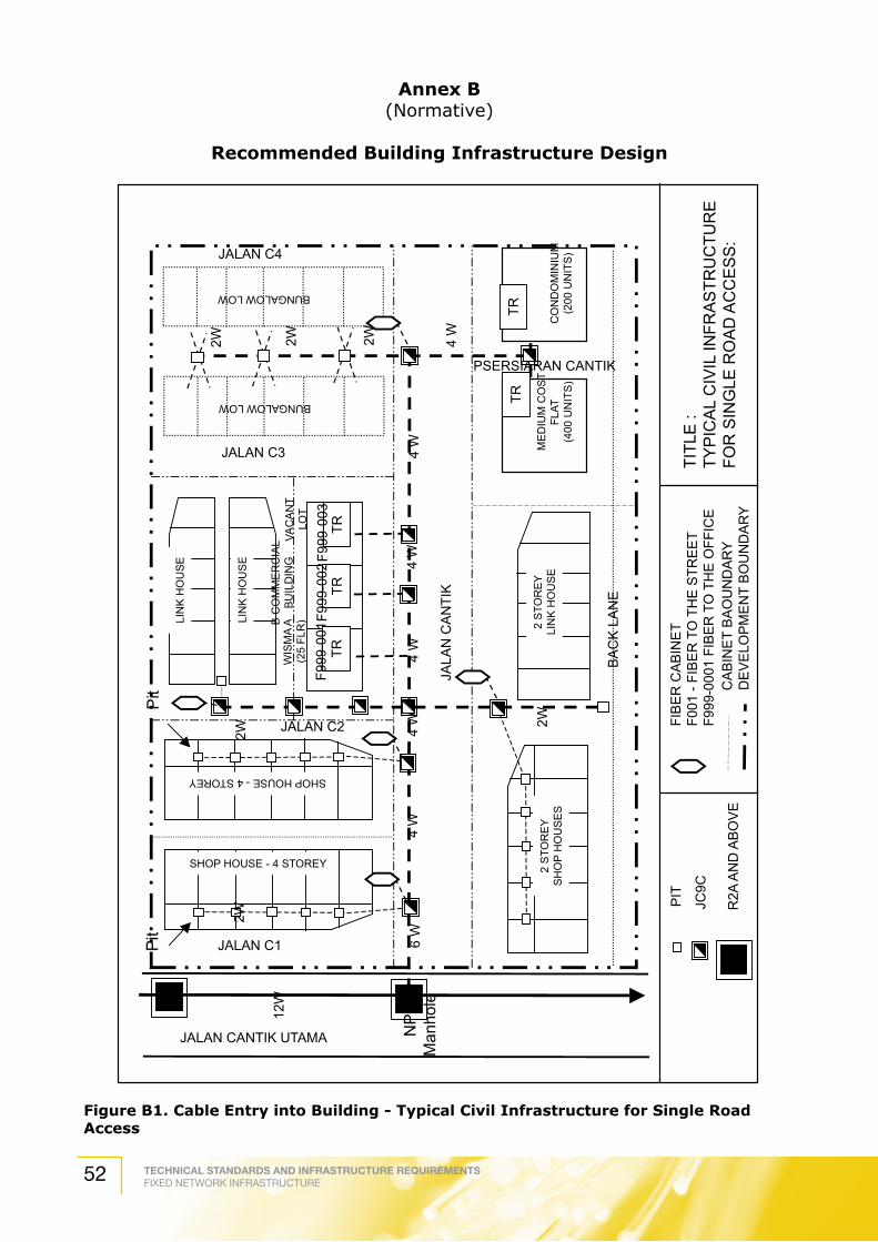
TECHNICAL STANDARDS AND INFRASTRUCTURE REQUIREMENTSFIXED NETWORK INFRASTRUCTURE52
Annex B(Normative)
Recommended Building Infrastructure Design
Figure B1. Cable Entry into Building - Typical Civil Infrastructure for Single Road Access
2W
Pit
2W
Pit
WIS
MA
A(2
5 FL
R)B C
OM
ME
RC
IAL
BU
ILD
ING
VAC
AN
TLO
T
LIN
K H
OU
SE
LIN
K H
OU
SE
SHOP HOUSE - 4 STOREY
SHOP HOUSE - 4 STOREY
BUNGALOW LOW
BUNGALOW LOW
2 S
TOR
EY
LIN
K H
OU
SE
2 S
TOR
EY
SH
OP
HO
US
ES
ME
DIU
M C
OS
TFL
AT(4
00 U
NIT
S)
CO
ND
OM
INIU
M(2
00 U
NIT
S)
TRTR
TRTR
TR
BA
CK
LA
NE
NP
Man
hole
12W
6 W
4 W
4 W
4 W
4 W
4 W
4 W
2W2W2W
2W
JALA
N C
AN
TIK
JALAN C4
JALAN C3
PSERSIARAN CANTIK
JALAN C2
JALAN C1
F999
-001
F999
-002
F999
-003
PIT
JC9C
R2A
AN
D A
BO
VE
FIB
ER
CA
BIN
ET
F001
- FI
BE
R T
O T
HE
STR
EE
TF9
99-0
001
FIB
ER
TO
TH
E O
FFIC
EC
AB
INE
T B
AO
UN
DA
RY
DE
VE
LOP
ME
NT
BO
UN
DA
RY
TITL
E :
TYP
ICA
L C
IVIL
INFR
AS
TRU
CTU
RE
FOR
SIN
GLE
RO
AD
AC
CE
SS
:
JALAN CANTIK UTAMA

TECHNICAL STANDARDS AND INFRASTRUCTURE REQUIREMENTSFIXED NETWORK INFRASTRUCTURE 53
Figure B2. Cable Entry into Building - Typical Civil Infrastructure for Multiple Road Access
2W
Pit
2W
Pit
LIN
K H
OU
SE
LIN
K H
OU
SE
SHOP HOUSE - 4 STOREY
SHOP HOUSE - 4 STOREY
BUNGALOW LOW
BUNGALOW LOW
2 S
TOR
EY
LIN
K H
OU
SE
ME
DIU
M C
OS
TFL
AT(4
00 U
NIT
S)
CO
ND
OM
INIU
M(2
00 U
NIT
S)
TRTR
JALA
N N
IRW
AN
A
NP
Man
hole
12W
2W2W
2W
JALAN P4
JALAN P3
JALAN P2
JALAN P1
PIT
JC9C
R2A
AN
D A
BO
VE
FIB
ER
CA
BIN
ET
F001
- FI
BE
R T
O T
HE
STR
EE
TF9
99-0
001
FIB
ER
TO
TH
E O
FFIC
EC
AB
INE
T B
AO
UN
DA
RY
DE
VE
LOP
ME
NT
BO
UN
DA
RY
TITL
E :
TYP
ICA
L C
IVIL
INFR
AS
TRU
CTU
RE
FOR
MU
LTIP
LE R
OA
D A
CC
ES
S
JALAN MEGAWATI UTAMA
2 S
TOR
EY
LIN
K H
OU
SE
PE
RS
IAR
AN
WA
WA
SA
N
PR
OP
OS
ED
PE
TRO
LS
TATI
ON
.
VAC
AN
TLO
TVA
CA
NT
LOT
LOR
ON
G P
UN
CA
K IN
DA
H
6 W
4 W
4 W
4 W
4 W
2W
4 W
4 W
6 W
JALA
N P
UN
CA
K S
ETI
A
BA
CK
LA
NE

TECHNICAL STANDARDS AND INFRASTRUCTURE REQUIREMENTSFIXED NETWORK INFRASTRUCTURE54
Fig
ure
B3
. C
ab
le E
ntr
y i
nto
Bu
ild
ing
, Tele
com
mu
nic
ati
on
s R
oo
m o
n F
irst
Flo
or
405m
m x
230
mm
OPE
NIN
G CO
MPL
ETE
WIT
H H
ARDW
OO
D C
OVE
R
CABL
E TR
AY S
UPP
ORT
AT
450m
m I
N T
ERVA
L
RACK
RIS
ER
RACK
RIS
ER C
ABIN
ET
405m
m x
230
mm
OPE
NIN
G W
ITH
HAR
DWO
OD
CO
VER
BE
AM
150m
m M
IN.C
LEAR
ANCE
CABL
E TR
AY S
UPP
ORT
AT
450m
m I
N T
ERM
AL
CABL
E TR
AY
100m
m P
VC P
IPE
MAN
HO
LE
BASE
MEN
T
BEAM
GR
OU
ND
FLO
OR
B
B
T/R
RO
OM
1st.
FLO
OR
CABL
E TR
AY
CA
BLE
EN
TR
Y IN
TO
BU
ILD
ING
TE
LEC
OM
MU
NIC
AT
ION
S
EQ
UIP
ME
NT
ON
1st
. FLO
OR
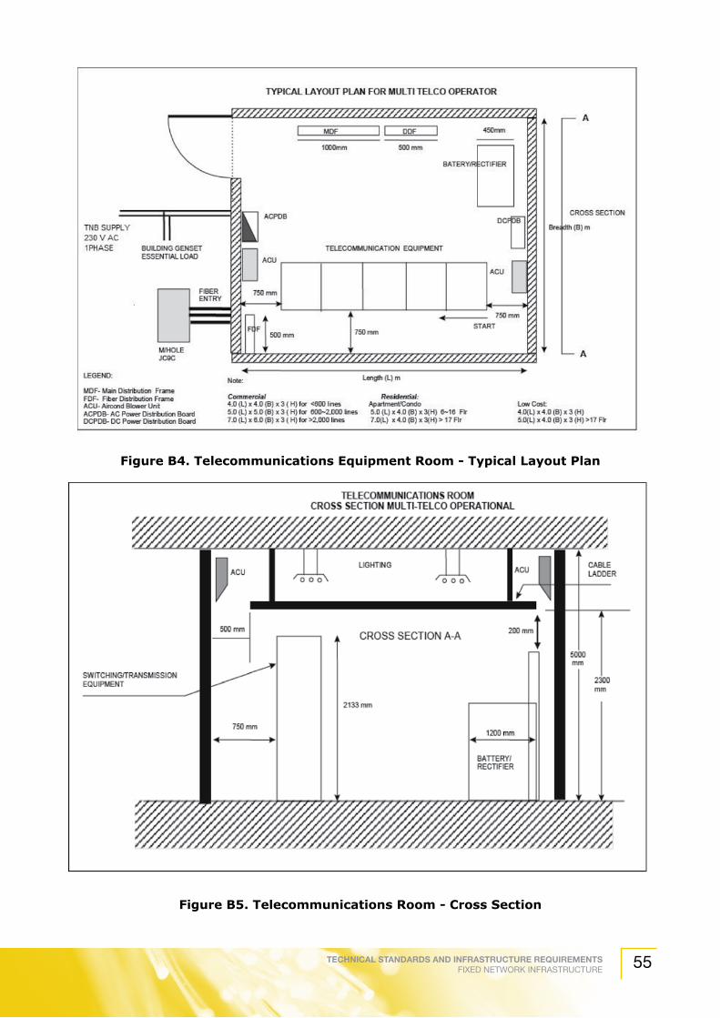
TECHNICAL STANDARDS AND INFRASTRUCTURE REQUIREMENTSFIXED NETWORK INFRASTRUCTURE 55
Figure B4. Telecommunications Equipment Room - Typical Layout Plan
Figure B5. Telecommunications Room - Cross Section

TECHNICAL STANDARDS AND INFRASTRUCTURE REQUIREMENTSFIXED NETWORK INFRASTRUCTURE56
Figure B6. Telecommunications Room - Typical Cable Rack

TECHNICAL STANDARDS AND INFRASTRUCTURE REQUIREMENTSFIXED NETWORK INFRASTRUCTURE 57
Figure B7. Cable Boundary for Multi Storey Building (Copper, Coaxial (HFC) and Fiber) by either Building Owner or Network Provider

TECHNICAL STANDARDS AND INFRASTRUCTURE REQUIREMENTSFIXED NETWORK INFRASTRUCTURE58
B1. Riser Design and Allocation
B1.2 Riser
The riser may be shared with the other communication providers, all cables and equipment should be installed according to the space allocated. All cables and equipment should be properly tagged.
B1.3 Equipment Installation and Arrangement
All Fixed Network equipment inside the riser should be installed on the left-hand side of the wall (refer Figure B8 & B9.). All equipment should be installed on a secured orderly manner.
Figure B8. Equipment and Trunking Arrangements
Cellular Network Trunking
Fixed Network Trunking
Fixed Network Equipment
Broadcast BroadbandSystem Components
(wall mounted)
Communication Riser ArrangementPlan View
Broadcast Network Trunking
3000 mm 3000 mm

TECHNICAL STANDARDS AND INFRASTRUCTURE REQUIREMENTSFIXED NETWORK INFRASTRUCTURE 59
Figure B9. Telecommunications Riser Arrangements
Cellular Network Trunking Fixed Network Trunking
Broadcast BroadbandSystem Components
(wall mounted)
Communication Riser ArrangementFront View
Broadcast Network Trunking
3000 mm 3000 mm
1200 m
m

TECHNICAL STANDARDS AND INFRASTRUCTURE REQUIREMENTSFIXED NETWORK INFRASTRUCTURE60
Annex C(Normative)
Recommended Cable Distribution Design
Figure C1. Typical Structured Cabling In Commercial Building.
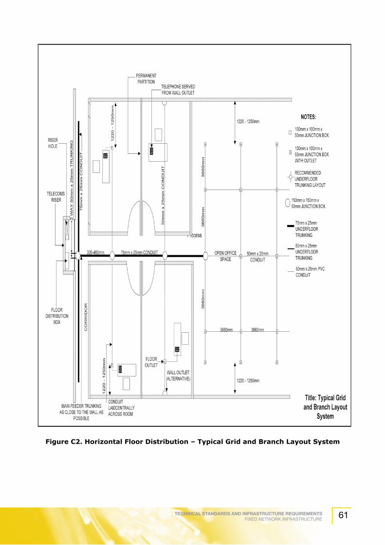
TECHNICAL STANDARDS AND INFRASTRUCTURE REQUIREMENTSFIXED NETWORK INFRASTRUCTURE 61
Figure C2. Horizontal Floor Distribution – Typical Grid and Branch Layout System

TECHNICAL STANDARDS AND INFRASTRUCTURE REQUIREMENTSFIXED NETWORK INFRASTRUCTURE62
Annex D(Normative)
Recommended Manhole Design
Figure D1. Typical Manhole Design
TableD1.TypicalManholeSpecifications
Manhole Frame and Cover
Carriageway level
Roof Thickness
Floor Thickness
11”
12”
6” 6”9”
24”
2.5”
Internal Height
Sump Hole
Note: Length and width of manhole refer to drawing.
10.5

TECHNICAL STANDARDS AND INFRASTRUCTURE REQUIREMENTSFIXED NETWORK INFRASTRUCTURE 63
Annex E(Normative)
Recommended Structured Cable Design, Installation and Testing
Details of accessories part of the cabling infrastructure are as follows:
E1. Transition Points
E1.1 General
Transition Points was used to provide a transition between cable types or configurations, for example from 25 pair to 4 pair or from round to flat cable.
It is a source of cross talk and attenuation and shall have impact on the performance of cable runs.
E1.2 Configuring Transition Points
If required, one TP is allowed between any FD and any TO. The transmission characteristic of the 90m maximum distance of the horizontal cable shall be maintained.
Cable elements at the TP shall be mechanically terminated.
The TP shall not be used as cross-connect and application specific equipment shall not be located there.
The TP may comprise of only passive connecting hardware.
E2. Horizontal Pathways
E2.1 General
Horizontal pathways define facilities for the installation of telecommunications from the FD to the work area.
Horizontal pathways encompass underfloor, access-floor conduit, tray and wireway, ceiling and perimeter facilities.
Pull boxes and splice boxes may be considered as horizontal pathways. In this guideline, pull boxes and splice boxes are considered as spaces.
The pathway for horizontal cabling shall be designed to support all telecommunications media recognized by this standard.
Horizontal pathways should not be located in elevator shafts.
The designer should design a trunk and branch layout that allows the horizontal cables to be bundled along main corridors and office throughways, emanating from the Floor Distributor to all work areas. This would allow the installer to employ more efficient pulling methods and causes less disruption to the customer’s daily operation.
E3. UnderfloorDuctingSystem
E3.1 General
Horizontal cableways or runways are required from the Floor Distributor or Telecommunications Closets to all telecommunication outlets in all rooms.

TECHNICAL STANDARDS AND INFRASTRUCTURE REQUIREMENTSFIXED NETWORK INFRASTRUCTURE64
There are a few methods in provisioning the ducting trunking :
a) Duct under the floor.
b) Pipes under the floor.
c) Hollow skirting along the wall.
d) Hollow dados along the wall.
e) Grooved picture rails or cable rails.
The one suitable in modern practice favours the use of (a) and (b) with the duct under the floor in rectangular shapes.
The material use for under floor duct shall be galvanized mild steel, fiber type, aluminum alloy or PVC with a minimum thickness of 1.6mm.
The under floor duct shall be buried 20mm to 25mm below floor screed level and their size depend on their distribution and the number of nodes required on a particular floor.
During the construction of the building, when under floor trunking system is assembled and screed being poured, extra precautions must be taken to ensure that the ducting / trunking are not damage and free from dirt and rubble.
The whole system shall be left clean and free from obstruction and fitted with draw wires before communication cables are installed.
E3.2 Layout of Under floor Ducting System
E3.2.1 Grid System
Grid system type is suitable for office and shopping complex with a large open space. Grid layout system using under floor duct with 3.6m x 3.6m grid type with floor outlets at the junction point.
The size of trunking is 50mm x 25mm (2” x 1”) for grids but a larger trunking will be required from the cable riser to the grid.
E3.2.2 Branching Layout System
Branching layout is suitable for the office building or shopping complex with a permanent partition and corridors. The branching layout system uses a central feeder trunking with branches at suitable position, normally 3m to 3.6m apart is recommended.
The telecommunication outlets shall be provided on these branches at every 3m apart.
The central feeder trunking must be designed and run along the public corridor as close to the wall as possible.
E3.2.3 Perimeter Layout System
Perimeter layout is using skirting duct with 4.5m x 3m (15’ x 10’) open floor grids with detachable covers.
E4 Conduit
E4.1 General
If conduit is requested by the customer, the installer shall provide conduit of required size

TECHNICAL STANDARDS AND INFRASTRUCTURE REQUIREMENTSFIXED NETWORK INFRASTRUCTURE 65
and type where indicated on job drawings.
In addition, the installer shall provide accessories required for a complete conduit installation.
E4.2 Types of conduit
All conduits shall comply with TIA/EIA 568A and 569. The types of conduit recommended are:
a) Metallic tubing
b) Rigid metal
c) High impact PVC
E4.3 Design Guidelines and Installation of Conduit
Conduit runs installed by the installer should not exceed 30m or contain more than two 90o bends without using appropriately sized pull boxes.
In a run requiring more than 2 bends or in excess of 30m, a pull box shall be installed between the second and the third bend as close as possible to the second bend.
Any single conduit run extending from a Telecommunications Closet shall not serve more than three outlets.
Conduits shall be incrementally increased in size from the furthest outlet box toward the Telecommunications Closet.
Conduits protruding through the floor in the Telecommunications Closet shall be terminated 25 mm to 50 mm above the floor surface and should be labeled.
The bending radius shall be as follows:
Table E1. Bending Radius for Conduit
Conduit Size Bend RadiusLess or equal to 50mm 6 times conduit size
Less or equal to 50mm 10 times conduit size
Fiber optic cable 10 times conduit size
The conduit fill table is as follows:
Table E2. Conduit Fill Table
Conduit size(mm)
4 pair cable (units)
25 pair cable (units)
20 5 -
25 8 1
50 26 6
75 60 14
Conduits shall be reamed to eliminate sharp edges and terminated with an insulated bushing.
A fishtape or pullcord (nylon string) shall be placed in installed conduits.

TECHNICAL STANDARDS AND INFRASTRUCTURE REQUIREMENTSFIXED NETWORK INFRASTRUCTURE66
E4.4 Outlet Boxes
The following table depicts the size of outlet boxes for the numerous sizes of conduits.
Table E3. Outlet Box Sizes for Different Conduit Sizes
Size of outlet box (mm) W x L x D Conduit trade size
50 x 75 x 64 21
120 x 120 x 64 35
100 x 100 x 57 27
E4.5 Pull Boxes
Pull boxes shall be used for the following purposes:
a) Fishing conduit runs
b) Pulling the cable to the box and then looping the cable to be pulled into the next length of conduit.
E5. Cable Trays and Wireways Installation
E5.1 General
If requested by the customer, the installer shall provide cable trays of required size and types when indicated on job drawings. The installer shall also provide accessories required for complete installation.
Trays and wireways may be located below or above the ceiling or within access floor.
E5.2 Types
The following are the example of cable trays and wireways:
a) Channel cable tray
b) Ladder cable tray
c) Solid bottom cable tray
d) Ventilated or through cable tray
e) Spine cable tray
f) Wireway
E5.3 Installation
Cable trays shall be supported by three basic support devices, namely cantilever brackets, trapeze or individual rod suspension. A support should be placed within 610mm on each side of any connection to a fitting. Wireways shall be supported on 1500mm centers unless designed for greater lengths.

TECHNICAL STANDARDS AND INFRASTRUCTURE REQUIREMENTSFIXED NETWORK INFRASTRUCTURE 67
Abrasive supports (such as threaded rod) shall have the portion within the cable protected with a smooth, non-scratching covering so that the cable can be pulled without any physical damage.
All wireways shall be compliant with TIA/EIA 568-A and 569.
Cable bundles in wireway or cable trays should be tied every 300mm or less.
When installing the cable trays or wireways, the inside of them shall be free of burns, sharp edges or projections that can damage the cable insulation.
The wireway shall be an unbroken length when it passes through a partition or wall.
Cables shall be properly fire-stopped when passed through cable trays or wireways.
Cable trays and wireways shall not be used as walkways or ladders unless specifically designed and installed for that purpose.
A minimum of 300mm access headroom shall be provided and maintained above a cable tray.
Care shall be taken that other building components such as air-conditioning ducts do not restrict access to cable trays or wireways.
Figure E1. Headroom above Cable Tray
Avoid excessive weight on cable at cable tray rungs to reduce compression of cables at the bottom.
Fiber cables shall be placed on top of copper cables.
E6. Trunking
Cable trunking shall comply with the requirements addressed in TSIR (Technical Standards and Infrastructure Requirements).
E7. Ceiling Pathway
E7.1. General
Ceiling areas are sometimes used as pathways for telecommunications cable.
E7.2. Considerations
Inaccessible ceiling areas, such as lock-in type ceiling tiles, drywall or plaster should not be used as distribution pathways.
The ceiling tiles are of the removable or lay in type and placed at a maximum height of 3.4 m above the floor.
300mm Headroom

TECHNICAL STANDARDS AND INFRASTRUCTURE REQUIREMENTSFIXED NETWORK INFRASTRUCTURE68
Adequate and suitable space is available in the ceiling area for the distribution layout recommended.
Raceways are provided where required by codes or design.
E7.3. Design Guidelines
The design shall provide suitable means for supporting cables from the Telecommunications Closet to the work area to be served.
Suspended ceiling support wire or rod shall not be used for this purpose.
Cable shall not be laid directly from the ceiling tile or rails.
A minimum of 75mm in clear vertical space shall be available above the ceiling tile for the distribution cabling and pathway.
E7.4. Utility Columns
Utility column provide pathways for wires and cables from the ceiling to the work area.
Utility column should be attached to and supported by main ceiling support channel.
When utility columns are used, the main ceiling rails shall be rigidly installed and braced to overcome movement, both horizontal and vertical.
E7.5. Trays
When a tray is used in the ceiling area, conduits from the tray to outlet zones shall be provided unless otherwise permitted by code.
E7.6. Telecommunications Closet Termination
Trays and zone conduits within the ceiling shall protrude into the closet from 20 to 25 mm without a bend and above the 2.4m level.
E7.7. Hanging Pathways
In suspended ceilings and raised floor areas where walker ducts, cable trays or conduits are not available, the cables shall be bundled with plastic cable ties with particular care taken so as to maintain the geometry of the cable.
The cable bundling shall be supported with J-hooks attached to the existing building structure and framework at a maximum of 1.5m intervals. The bending radius and pulling tension of the cables shall be complied at all times. The maximum height from the ceiling shall be 75mm. This is illustrated in Figure E2.
Figure E2. Hanging Pathways
1.5 mMax=75 mm
No sharp edges Visible sag Cable is not tightly bundled

TECHNICAL STANDARDS AND INFRASTRUCTURE REQUIREMENTSFIXED NETWORK INFRASTRUCTURE 69
The cable bundle shall be less than 50 4-pair UTP cables.
The cable shall not be supported by attaching it to the ceiling support system in ceiling plenum environments.
In addition, the cable shall not rest on the ceiling tiles.
Plenum cable should be used in all appropriate areas.
E8. Raceway Installation
If requested by the customer, the installer shall provide raceways of required size and types when indicated on job drawings. The installer shall also provide accessories required for complete installation. Figure E3 illustrates a typical raceway.
Figure E3. Typical Perimeter Raceway
All surface metal and Fiber optic raceways shall comply with guidelines published by EIA/TIA 568-A and 569.
Raceways shall be routed in such a way so that interference with removal and installation of lighting fixtures and devices of other systems that require servicing or operation can be avoided.
Raceways shall be supported from concrete ceiling or ceiling beams at 1.5m maximum span intervals.
Raceways shall be provided to accommodate underfloor pedestal at 1.2m maximum span intervals.
Sharp burrs or edges shall be removed from raceways.
The raceways when completed shall have no cracks or openings at coupled sections.
Radius fittings shall be provided for turns and offsets to accommodate obstruction or elevation changes and maintain minimum cable bending radius.
E9. Distributors: Floor Distributor
E9.1 General
The Floor Distributor on each floor is the recognized location of the common access point for backbone and horizontal pathways.
The Floor Distributor shall be able to contain the telecommunication equipment, cable terminations and associated cross connect cabling.
telecommunications outlet

TECHNICAL STANDARDS AND INFRASTRUCTURE REQUIREMENTSFIXED NETWORK INFRASTRUCTURE70
The Floor Distributor shall be located as close as practicable to the center of the area served and preferably in the core area.
E9.2 Design Consideration
E9.2.1 General
Floor Distributor space shall not be shared with electrical installation other than those for telecommunication.
Equipment that are not related to the support of Floor Distributor shall not be installed in, passed through or enter the Floor Distributor.
E9.2.2 Size and Spacing
There should be a minimum of one closet per floor. Additional closets should be provided when:
a) The floor area to be served exceeds 1000 m2 or
b) The horizontal distribution distance to work area is more than 90 m
The additional Telecommunications Closet shall be one per 1000 m2.
The multiple closets on a floor shall be interconnected by a minimum of one conduit of 3-trade size or equivalent pathway.
Table E4 indicates the Telecommunications Closet size. The size is based on the assumption that the work area size is 10m2.
Table E4. Floor Distributor Sizing
Serving area (m2) Closet size (mm)
1000 3000 x 3400
800 3000 x 2800
500 3000 x 2200
E9.2.3 Floor Loading
The Floor Distributor shall be located on floor areas designed with a minimum floor loading of 2.4kPa.
E9.3 Provisioning
E9.3.1 Lighting
The lighting should be a minimum of 540 lux, measured in 1.0m above the finished floor in middle of aisles between cabinets.
The lighting should be controlled by one or more switches located near the entrance doors to the room.
E9.3.2 Power
The building owner shall supply a minimum of 240V AC 1-phase or 415V AC 3-phase (from electricity utility supplier). There shall be a minimum of two 240V AC duplex electrical outlets, each on separate circuits for equipment power.
TECHNICAL STANDARDS AND INFRASTRUCTURE REQUIREMENTSFIXED NETWORK INFRASTRUCTURE 71
If emergency power is available, consideration should be given to automatic switchover of power.
E9.3.3 Door
The door should be a minimum of 910 mm wide and 2000 mm high, without doorsill, hinged to open outward or slide side to side and fitted with an extra lock.
The door fitted to the room should be 2 hours fire rated doors as per “Jabatan Bomba dan Penyelamat” approval.
The door should be locked at all times and only authorized telecommunication personnel are allowed to access the room.
E9.3.4 Interior Finishing
The floor of the Telecommunications Room should be of a material that is easy to clean and not susceptible to accumulation of dust. The flooring should be of anti-static vinyl type mat.
E9.4 Closet Penetration
Sleeves or slots through the closet floor should be near to the door. Sleeves or slot shall not be left open unless during cable installation and shall be properly fire-stopped.
Horizontal pathways are also considered as closet penetration. This will be covered in the respective section.
E9.5 Security and Fire Protection
The Network Provider should care for its own equipment security and should take the necessary steps to protect the equipment.
Each Network Provider is required to ensure that any sub-installer, agent, representative or any third party representing that Network Provider should take care to not damage or harm another Network Provider’s equipment.
Each Network Provider should also have the responsibility and duty to keep the telecommunications closet secure and protected from vandalism or theft of any kind or nature.
E9.6 Environmental Consideration
The HVAC should be provided 24 hours a day, 365 days per year basis. If an emergency power supply is available in the building, consideration shall be given to connecting the HVAC system serving the Telecommunications Room to the emergency supply.
The temperature and relative humidity should be maintained between 20oC to 30oC and 30% - 80% respectively, at all times.
E9.7 Connecting Hardware in FD
E9.7.1 General
A connector consists of a device or a combination of device to connect two cables or cable elements.

TECHNICAL STANDARDS AND INFRASTRUCTURE REQUIREMENTSFIXED NETWORK INFRASTRUCTURE72
E9.7.2 Installation Practices
The connecting hardware is installed in a FD to provide direct or indirect connection between backbone and horizontal cabling. It is also to provide connection to active equipment.
The connecting hardware shall be installed to permit minimal signal impairment and shield effectiveness (if shielded cables are used). Proper cable preparation, termination practices and well-organized cable management shall be employed.
The installation of connecting hardware shall allow room for mounting telecommunications equipment concerning the cabling system. Racks shall have adequate clearances for access and cable dressing space.
E9.7.3 Patching Options
There are two patching methods, namely direct patching (inter-connection) and indirect patching (cross-connection).
Direct patching performs a direct patch connection between the equipment ports and the horizontal cabling (patch panels). This method generates less crosstalk with the cabling, as a result of few connection points. Figure E4 illustrates the direct patching method.
Figure E4. Direct Patching Method
Indirect patching or cross connection uses an intermediate patch panel to present the equipment ports. Extra connection point in this method allows room for greater crosstalk which becomes prominent with applications using the full signaling bandwidth of the cable at the maximum of 90m horizontal cable distance. Figure E5 depicts the indirect patching method.
End User Equipment
TelecommunicationsOutlet
WORK AREAFLOOR DISTRIBUTOR
TRANSMISSION EQUIPMENT(Eq: Ethernet Repeater)
HORIZONTAL CABLING
HORIZONTAL PATCH PANEL

TECHNICAL STANDARDS AND INFRASTRUCTURE REQUIREMENTSFIXED NETWORK INFRASTRUCTURE 73
Figure E5. Indirect Patching Method
E10. Backbone Cabling and Pathways
E10.1 Backbone Cabling
E10.1.1 Physical Topology
The hierarchical levels of cross-connects shall not exceed two in the building backbone cabling. This is to restrict signal deterioration for passive systems and to simplify administration in keeping track of cables and connections.
A single backbone cabling cross-connect may meet the cross-connect requirements of the entire backbone sub-system.
Avoid installing in areas where sources of high levels of EMI/RFI may exist.
Bridge taps shall not be used in the backbone cabling system. Cable elements that are terminated at different locations may be part of the same cable over a portion of distance or may use individual cables over the entire distance. Figure E6 depicts an example of backbone star topology.
End User Equipment
TelecommunicationsOutlet
WORK AREA FLOOR DISTRIBUTOR
TRANSMISSION EQUIPMENT(Eq: Ethernet Repeater)
HORIZONTAL PATCH PANEL
PRESENTATION PATCH PANEL

TECHNICAL STANDARDS AND INFRASTRUCTURE REQUIREMENTSFIXED NETWORK INFRASTRUCTURE74
Figure E6. Physical Topology For Backbone Topology
The star topology is applicable to the cable elements of the transmission medium, such as individual fibers or pairs.
E10.1.2. Backbone Media Selection
The preferred cable types are as follows:
a) 62.5/125µm multi-mode optical Fiber
b) 50/125µm multi-mode optical Fiber
c) 8/125µm single-mode optical Fiber
d) 100Ω balanced cable
Table E5. Backbone Media Selection
Application ClassBackbone Length/Type of cable
0m to 90m 90m to 160m 160m to 500mA Cat 3-6 Cat 3-6 Cat 3-6
B Cat 3-6 Cat 3-6 Cat 3-6
C Cat 3-6 Cat 5e,6 Optical Fiber
D Category 5e,6 Optical Fiber Optical Fiber
CDCampusBackboneCable
CampusBackboneCable
HorizontalCable
Optional Transition PointOptional Cables
BD
TP
TP
BD
FD
TO
TOTOTO
TO
FD FDFD
BD

TECHNICAL STANDARDS AND INFRASTRUCTURE REQUIREMENTSFIXED NETWORK INFRASTRUCTURE 75
E10.2. Cable Distance
The maximum cabling distance between the FD to BD shall be 500m.
The jumper and patch cord lengths shall not exceed 20m. If the length exceeds 20m, the length shall be deducted from the maximum permissible backbone cable length.
The length of cables that connect telecommunications equipment, such as PBX, directly to a BD shall not exceed 30m. If the length exceeds this value, then the backbone distance shall be reduced accordingly.
E10.3 Pathways
E10.3.1. General
Pathways may be defined within trunking, conduit, tray work or ducting. It provides the means of placing cables from:
a) The entrance room or space to Telecommunications Closet.
b) Telecommunications Rooms to either the entrance room or telecommunications closets.
It shall protect installed cabling, provide adequate capacity for the cable being carried and enable minimum bending radius to be maintained.
A separate cable shall be run from the Telecommunications Room to each floor except on the rare occasion when the smallest size of cable will surface for two floors.
Cable tray can be fixed for telecommunication cables (fixed networks), cellular cables and broadcast cables. The arrangements of these cables shall be as follows:
a) From left side is for telecommunication cables.
b) Center of cable tray is for cellular cables.
c) From right side is a broadcast cable.
E10.3.2. Design Guidelines
The Telecommunications Rooms shall be connected to the backbone pathway for cabling to the Telecommunications Closet.
For Telecommunications Closet termination, tray and zone within the ceiling shall protrude into the closet from 25 mm to 50 mm, without a bend and above the 2.4m level.
Pathways shall not be routed through gaps between the floor or ceiling structure and a curtain wall.
Pathways should not be located in elevator shafts.
The integrity of all firestoping assemblies shall be maintained when penetrated by cables, wires and pathways.
The conduit fill for backbone cable should comply with the following table.

TECHNICAL STANDARDS AND INFRASTRUCTURE REQUIREMENTSFIXED NETWORK INFRASTRUCTURE76
Table E6. Conduit Fill for Backbone Cabling
Conduit Area of conduit
Trade SizeInternal Diameter
Area = 79D2
Max. Occupancy Recommended Min. bending radius
A B C D E
Total 100%
1Cable (53% fill)
2 Cables (31% fill)
< 3 cables (40% fill)
Layers of steal within sheath
Other sheaths
mm mm2 mm2 mm2 mm2 mm mm
21 (3/4) 20.9 345 183 107 138 210 13027 (1) 26.7 559 296 173 224 270 160
35 (1¼) 35.1 973 516 302 389 350 21041 (1 ) 40.9 1322 701 410 529 410 25053 (2) 52.5 2177 1154 675 871 530 320
63 (2 ½) 62.7 3106 1646 963 1242 630 63078 (3) 77.9 4794 2541 1486 1918 780 78091 (3 ) 90.1 6413 3399 1988 2565 900 900103 (4) 102.3 8268 4382 2563 3307 1020 1020129 (5) 128.2 12 984 6882 4025 5194 1280 1280155 (6) 154.1 18 760 9943 5816 7504 1540 1540
E10.3.3 Pull Box and Splice Box Design Guidelines
Pull boxes shall be used for the following purposes:
a) Fishing the conduit run.
b) Pulling the cable to the box and looping the cable to be pulled into the next length of conduit.
Pull boxes shall not be used for splicing cables.
Splice boxes are intended to be used for splicing in addition to pulling cable.
A pull box shall be placed in a conduit run where
a) The length is more than 30m.
b) There are more than two 900 bend.
c) If there is a reverse bend in the run.
Pull and splice boxes shall be placed in a straight section of a conduit and not used in lieu of a bend. Conduits fittings shall not be used in place of pull or splice boxes.
The pull box and splice box sizing are as indicated in the tables below.
Table E7. Pull Box Sizing
Conduit trade size
Width (mm)
Length (mm)
Depth (mm)
Width increase for additional conduit
27 (1) 102 406 76 51
35 (1 ¼) 152 508 76 76
41( 1 ½) 203 686 102 102

TECHNICAL STANDARDS AND INFRASTRUCTURE REQUIREMENTSFIXED NETWORK INFRASTRUCTURE 77
53 (2) 203 914 102 127
63 (2 ½) 254 1067 127 152
78 (3) 305 1219 127 152
91 (3 ½) 305 1372 152 152
103 (4) 381 1524 203 203
Table E8. Splice Box Sizing
Conduit trade size
Width (mm)
Length (mm)
Depth (mm)
Width increase for additional conduit
27 (1) 300 810 100 75
35 (1 ¼) 355 915 125 100
41( 1 ½) 450 990 150 100
53 (2) 500 1065 175 125
63 (2 ½) 60 1220 200 150
78 (3) 760 1375 225 150
91 (3 ½) 915 1525 255 175
103 (4) 1065 1675 275 175
E10.3.4. Establishment of Pathways
The two methods for establishing a pathway when the backbone cable run between floors shall be sleeve and slots.
Figure E7. Sleeve and Slot Designs
The minimum diameter of sleeves shall be 100 mm. The sleeve should extend form 25 mm to 100 mm above the floor height.
The minimum slot size should be 150 mm x 225 mm.
Table E9 indicates the minimum size for slots and sleeves based on the size of the floor area serviced by the cables feeding that floor.
Sleeve Slot
Table E7. Pull Box Sizing (continue)

TECHNICAL STANDARDS AND INFRASTRUCTURE REQUIREMENTSFIXED NETWORK INFRASTRUCTURE78
Table E9. Sleeve Requirements Based On Floor Area
Sleeve requirements
Floor area (m2) Number of sleeves
Up to 4500 2
4500 to 9000 3
9000 to 28 000 4
28 000 to 45 000 5
Table E10. Slot Requirements Based On Floor Area
Slot requirements
Floor area served by shaft (m2) Slot sizes (mm)Up to 23,000 150 x 225
23,000 to 50,000 150 x 45050,000 to 90,000 225 x 50090,000 to 130,000 300 x 500130,000 to 185,000 375 x 600
E10.3.5. Securing Vertical Cable Runs
The installer shall use an extra support for vertical cable runs when the length of run is more than 2 floors or when the cable is heavy (such as high pair counts cables).
The cable run can be supported via a support strand between the highest floor and the basement.
The installer shall strap the cable to the support strand every 900 mm with a minimum of three ties per floor, using cable ties.
To remove the stress of the bending radius at the top of the run, support the cables with a Kellum grip or similar device. The Kellum grip should grasp a minimum of 300 mm of cable length immediately below the bend.
If a support strength is not required or inappropriate, the installer shall follow the procedures below:
a) Affix a support collar around the cable where it passes down through a slot or sleeve.
b) Rest the support collar on the edge of the opening so that it supports the weight of the cable.
c) Wire-tie the cable between collar-supported points to supporting members on each floor.

TECHNICAL STANDARDS AND INFRASTRUCTURE REQUIREMENTSFIXED NETWORK INFRASTRUCTURE 79
Figure E8. Support Collar
Inadequate support of the cable over the length of the run will result in damage to the internal components of the cable, namely fiber strands and copper conductors.
Care shall be taken so that there is no compression of the jacket of optical fiber cables with ties or other support.
E11. Campus Cabling
E11.1 Physical Topology
Campus backbone cabling extends from the CD to the BD. Campus cabling may employ star topology. The campus cabling sub-system is as illustrated in Figure E9.
Support Collar

TECHNICAL STANDARDS AND INFRASTRUCTURE REQUIREMENTSFIXED NETWORK INFRASTRUCTURE80
Figure E9. Campus Cabling Sub-System
Depending on the physical characteristics of a site, cable elements that are terminated at different locations may be a part of the same cable over a portion of distance, or may use individual cable over the entire distance.
There shall be only one cross-connect from the BD to the CD.
Cross-connects for different types of cables must be located in the same facilities.
Installation shall not be done in areas where EMI and RFI sources are prominent. Bridge taps shall not be used in the backbone cabling system.
E11.2 Cable Types
The preferred cable types shall be as follows:
a) 62.5/125µm multi-mode optical fiber
b) 50/125µm multi-mode optical fiber
c) 8/125µm single-mode optical fiber
d) 100Ω balanced cable
TO
TO
TO
TOTP FD
FD
FD
FD
FD
FD
FD
FD
FD
BD
BD CD
TP OPTIONAL
Building A Building BCampus
CAMPUS CABLING SUB-SYSTEM
Cabling
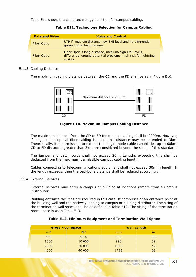
TECHNICAL STANDARDS AND INFRASTRUCTURE REQUIREMENTSFIXED NETWORK INFRASTRUCTURE 81
Table E11 shows the cable technology selection for campus cabling.
Table E11. Technology Selection for Campus Cabling
Data and Video Voice and Control
Fiber Optic UTP if medium distance, low EMI level and no differential ground potential problems
Fiber OpticFiber Optic if long distance, medium/high EMI levels, differential ground potential problems, high risk for lightning strikes
E11.3 Cabling Distance
The maximum cabling distance between the CD and the FD shall be as in Figure E10.
Figure E10. Maximum Campus Cabling Distance
The maximum distance from the CD to FD for campus cabling shall be 2000m. However, if single mode optical fiber cabling is used, this distance may be extended to 3km. Theoretically, it is permissible to extend the single mode cable capabilities up to 60km. CD to FD distances greater than 3km are considered beyond the scope of this standard.
The jumper and patch cords shall not exceed 20m. Lengths exceeding this shall be deducted from the maximum permissible campus cabling length.
Cables connecting to telecommunications equipment shall not exceed 30m in length. If the length exceeds, then the backbone distance shall be reduced accordingly.
E11.4 External Services
External services may enter a campus or building at locations remote from a Campus Distributor.
Building entrance facilities are required in this case. It comprises of an entrance point at the building wall and the pathway leading to campus or building distributor. The sizing of the termination wall space shall be as defined in Table E12. The sizing of the termination room space is as in Table E13.
Table E12. Minimum Equipment and Termination Wall Space
Gross Floor Space Wall Length
m2 Ft2 mm in
500 5000 990 39
1000 10 000 990 39
2000 20 000 1060 42
4000 40 000 1725 68
Maximum distance = 2000m
CD FD
TECHNICAL STANDARDS AND INFRASTRUCTURE REQUIREMENTSFIXED NETWORK INFRASTRUCTURE82
Gross Floor Space Wall Length
m2 Ft2 mm in
5000 50 000 2295 90
6000 60 000 2400 96
8000 80 000 3015 120
10 000 100 000 3630 144
Table E13 Minimum Equipment and Termination Room Space
Gross Floor Space Room Dimensionsm2 Ft2 mm In
7000 70 000 3660 x 1930 12 x 6.310 000 100 000 3660 x 1930 12 x 6.320 000 200 000 3660 x 2750 12 x 940 000 400 000 3660 x 3970 12 x 1350 000 500 000 3660 x 4775 12 x 15.660 000 600 000 3660 x 5588 12 x 18.380 000 800 000 3660 x 6810 12 x 22.3100 000 1000 000 3660 x 8440 12 x 27.7
E12. Distributors - Telecommunications Room or Campus / Building Distributor
E12.1 General
Telecommunications Room is a centralized space for telecommunications equipment, such as PABX, computing and networking equipment that serves specific occupants of the building.
The Telecommunications Room shall accommodate equipment directly related to the telecommunication system and its environmental support system.
E12.2 Design Consideration
E12.2.1 Site Selection
The Telecommunications Room shall be placed in an area where it is flood free, to avoid dampness and dirt, preferably at the ground floor.
It shall be located away from refuge, rubbish area and chute.
In addition, it shall be located in a place that is free of perceptible vibration.
The Telecommunications Room equipment should not be installed in places where it will get direct sunlight. If this is unavoidable, a thick curtain of a Venetian blind shall be used to prevent the rays of sunlight from falling on the equipment.
E12.2.2 Floor Loading
The Telecommunications Room should have a floor loading capacity that is sufficient to bear both the distributed and concentrated load of the installed equipment.
The Telecommunications Room shall be designed for a minimum distributed load of 500 kg/m2 and concentrated floor loading of 910 kg/m2 is depending on the type and capacity of the telecommunication equipment.
Table E12. Minimum Equipment and Termination Wall Space (continue)

TECHNICAL STANDARDS AND INFRASTRUCTURE REQUIREMENTSFIXED NETWORK INFRASTRUCTURE 83
If unusual heavy equipment is expected, the above specification may have to be increased.
E12.2.3 Water Infiltration
The Telecommunications Room shall not be located below water level unless preventive measurements against water infiltration are employed.
The room shall be free of water and flood.
A floor drain should be provided within the room if risk of water ingress exists.
E12.2.4 HVAC
The Telecommunications Room should be located with ready access to the main HVAC delivery system.
E12.2.5 Electromagnetic Interference
The room shall be located away from sources of electromagnetic interference at a distance which will reduce the interference to 3.0V/m throughout the frequency spectrum.
It is desirable to locate the equipment room close to the main backbone pathway.
E12.2.6 Size
The Telecommunications Room shall be sized in accordance to the requirements of specific equipment and shall include future and current needs.
The floor area should include the termination and transmission equipment and depend on the type and ultimate demand of the building.
For special use building such as hospital, laboratories and etc, the Telecommunications Room (TR) floor space shall be based according to the number of work areas and not on the usable floor area.
The TR floor space for a normal building and a special use building shall be as per Table E14.
TableE14.TRFloorSpaceforNormalOfficeBuilding
TotalUsablefloorspace(x) Telecommunications Room space (length x base x height) in m
< 6000m2 4 x 3.5 x 36,000m2 to 20,000m2 5 x 5 x 320,000m2 to 60,000m2 7 x 5 x 3
> 60,000m2 7 x 5 x 3
Table E15. TR Floor Space for Special Use Building
Work areas Area (m2)
Up to 100 14
101 to 400 37
401 to 800 74
801 to 1200 111

TECHNICAL STANDARDS AND INFRASTRUCTURE REQUIREMENTSFIXED NETWORK INFRASTRUCTURE84
E12.2.7 Guidelines for Other Equipment / Furniture
Ducting, sewage pipes, air conditioning outlet pipes should not pass through the Telecommunications Room.
It is recommended that a table and chair be provided by the owner in the Telecommunications Room.
E13. Provisioning
E13.1 Layouts
A minimum of clear floor space of 750 mm is crucial in front of all accessible points of the equipment in order to provide adequate working space for installation, testing and maintenance service.
E13.2 Clearance Heights
The clear ceiling height of the Telecommunications Room shall not be less than 2440 mm, so as to enable installation of equipment, cabinets and cabling.
E13.3 Power
The building owner shall provide a electrical supply from electric utility supplier at a nominal voltage of 415V, 3 phase, 4 wire, 50 Hz system or at a nominal voltage of 230V, 1 phase, 2 wire, 50 Hz system with solidly earth system.
The building owner shall provide a minimum of two 13A, 3 pins outlet points on separate circuits.
Grounding bar that is connected to the building’s master ground bar must have an earth resistance of less than 5 Ohms.
E13.4 Contaminants
The Telecommunications Room shall be free from contaminants and pollutants that could affect the operation and material integrity of the installed equipment.
If the contamination level is greater than the values listed in table below, vapours barriers, positive room pressure or absolute filter shall be provided.
Table E16. Contamination Limits
Contaminant Concentration
Chlorine 0.01 ppm
Dust 100 mg/m3/24h
Hydrocarbon 4 mg/m3/24h
Hydrogen Sulphide 0.05 ppm
Nitrogen Oxide 0.1 ppm
Sulphur Dioxide 0.3 ppm
If the Telecommunications Room is situated on the car park floor, it must be completely enclosed to prevent dust from entering the room. Louver type of doors and windows shall be avoided.
E13.5 HVAC Supply
The HVAC should be provided 24 hours a day, 365 days per year basis. If an emergency power supply is available in the building, consideration shall be given to connecting the

TECHNICAL STANDARDS AND INFRASTRUCTURE REQUIREMENTSFIXED NETWORK INFRASTRUCTURE 85
HVAC system serving the Telecommunications Room to the emergency supply.
The temperature and humidity should be maintained between 20 oC – 30 oC and 30% - 80% respectively, at all times.
The Telecommunications Room should be provided with a minimum of two 2.5 Hp air-conditioning units. Should there be any expansion an incremental of 2.5 Hp unit each shall be added.
The ambient temperature and humidity shall be measured at a distance of 1.5m above floor level after the equipment is in operation, at any point along the equipment aisle center line.
E13.6 Lighting
The lighting should be a minimum of 540 lux, measured in 1m above the finished floor in middle of aisles between cabinets.
The lighting should be controlled by one or more switches located near the entrance doors to the room.
E13.7 Door
The door should be a minimum of 960 mm wide and 2000 mm high without doorsill and shall be fitted with a lock.
If it is anticipated that large equipment will be delivered to the Telecommunications Room, a double door (1820 mm wide by 2280 mm height) without doorsill and center post is recommended.
The door fitted to the room shall be 2-hours fire rated doors as per “Jabatan Bomba dan Penyelamat” approval.
The door should be locked.
The door shall be labeled accordingly and the words shall be clearly displayed on the door of the Telecommunications Room, e.g. “BILIK TELEKOMUNIKASI” as per “Jabatan Bomba dan Penyelamat” approval.
E13.8 Fire Alarm System
A fire alarm system should be installed in the Telecommunications Room as per “Jabatan Bomba dan Penyelamat” approval. The alarm should be connected to main building alarm.
E13.9 Interior Finishes
The floor of the Telecommunications Room should be of a material that is easy to clean and not susceptible to accumulation of dust. The flooring should be of anti-static vinyl type mat.
The wall of the Telecommunications Room should be of white colour and preferably have impervious smooth glossy finish to minimize the accumulative of dust.
E14. Telecommunications Room: Equipment Termination Layout
The BD/CD is located at the Telecommunications Room and is the hub of the generic / structured cabling systems.

TECHNICAL STANDARDS AND INFRASTRUCTURE REQUIREMENTSFIXED NETWORK INFRASTRUCTURE86
The installer shall ensure that the layout of the Telecommunications Room is such that the interconnecting sections are near each other so as to ensure short cross-connect length and avoid overloading the wire management ring runs.
The Telecommunications Room or CD/BD consists of any or all of the five components:
a) Backbone cabling - The size depends on the type of transmission media. It can be relatively small for fiber or large for UTP cables.
b) Horizontal cabling - There might be a sizeable number of horizontal cables terminating in the FD to serve users in the local area.
c) System cabling.
d) Inter building cabling - In campus or multi building networks, cabling between buildings originates and terminates at the BD.
e) Miscellaneous cabling - This includes the connections representing other services such as BMS, CATV, CCTV and security.
The installer shall not install the cabinets or distribution frames near high power electrical installations such as transformers, elevators or generators.
The recommended distribution frames component layout is as illustrated in Figure E11.

TECHNICAL STANDARDS AND INFRASTRUCTURE REQUIREMENTSFIXED NETWORK INFRASTRUCTURE 87
Figure E11. Distribution Frames Component Layout
BACKBONE
BACKBONE
BACKBONE
BACKBONEMISCELLANEOUS
SYSTEM
SYSTEM
SYSTEM
SYSTEM
INTERBUILDING
INTERBUILDING
HORIZONTAL
HORIZONTAL
HORIZONTAL

TECHNICAL STANDARDS AND INFRASTRUCTURE REQUIREMENTSFIXED NETWORK INFRASTRUCTURE88
E15. Distributors: Common Installation Practice
E15.1 General
This section discusses on the installation common practices for Telecommunications Closet and Telecommunications Room that should be done by installers provisioned by the network provider.
E15.2 Supply and installation practice of distribution area components
E15.2.1 Patch Cords
Installers shall supply patch cords complete with termination.
The patch cord used shall be a minimum of 4-pair stranded, UTP Cat 5e, preferably factory-terminated cable.
Fiber optic patch cord should be of factory terminated buffered, graded index fiber multimode or single mode with Duplex SC type connectors. Other small form factor connectors (e.g. MT-RJ) may also be used.
Installers must adhere strictly to the bending radius and pulling tension rules at all times during handling and installation.
In addition, installer should be aware that patch cords need to be of the same performance category.
Installers should make sure that the connecting hardware used is of the same performance category.
E15.2.2 Cable Ties
The installer shall supply the cable ties (Velcro may be used) for proper administration of the distribution rack.
Staples shall not be used for category 5 installations.
The geometry of the cables shall not be changed during installation.
The cable shall be able to slide freely through the tie wrap and should be finger tight. If the wrap cable is too tight, the geometry of the pairs in the cable would be changed and this degrades the cable performance.
The installer should use the cable ties to manage the cable bundles and to provide a neat presentation. In addition, the cables should show no sign of distortion.
E15.2.3 Patch Panels
The installer shall supply the patch panels complete with both front and back cable management units.
The patch panel supplied should fit into 19” equipment rack.
E15.2.4 Cabinets/ Distribution Rack
The installer shall supply the distribution rack complete with the accessories needed to install the rack.
The distribution rack should be of 19” with the appropriate height as specified by the customer.
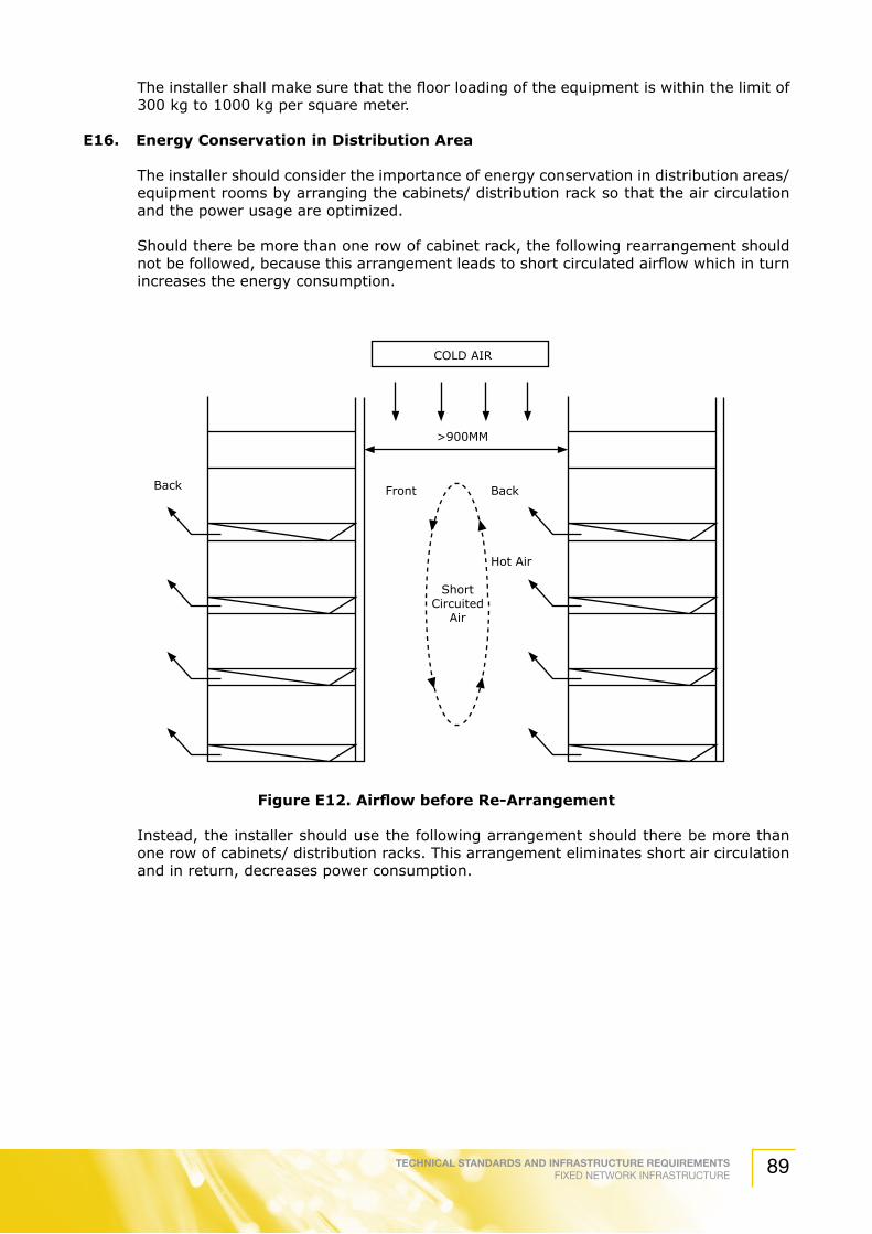
TECHNICAL STANDARDS AND INFRASTRUCTURE REQUIREMENTSFIXED NETWORK INFRASTRUCTURE 89
The installer shall make sure that the floor loading of the equipment is within the limit of 300 kg to 1000 kg per square meter.
E16. Energy Conservation in Distribution Area
The installer should consider the importance of energy conservation in distribution areas/ equipment rooms by arranging the cabinets/ distribution rack so that the air circulation and the power usage are optimized.
Should there be more than one row of cabinet rack, the following rearrangement should not be followed, because this arrangement leads to short circulated airflow which in turn increases the energy consumption.
FigureE12.AirflowbeforeRe-Arrangement
Instead, the installer should use the following arrangement should there be more than one row of cabinets/ distribution racks. This arrangement eliminates short air circulation and in return, decreases power consumption.
COLD AIR
>900MM
Front
ShortCircuited
Air
Back Back
Hot Air

TECHNICAL STANDARDS AND INFRASTRUCTURE REQUIREMENTSFIXED NETWORK INFRASTRUCTURE90
FigureE13.AirflowafterRe-Arrangement
E17. Patch Panels Terminations Layout
Patch panels, when terminated on a rack, should have the appropriate layout for efficient use, maintenance and expansion of the patch field.
The rack should not be closer than 750 mm to any wall or equipment behind, front or to one side. Multiple racks may be ganged together side-to-side.
If open rack is used, anchor the racks to the floor using lag bolts in concrete and toggle bolts in raised floors. Anchor the top of the rack to the rear wall or ceiling. In the case of multiple rack ganged together, bolt all racks together and secure them at every second rack.
Place patch panels on the rack relative to the media type. Fiber patch panels should be placed at the near top of the rack to protect the terminations from potential harm.
Install a rack mount storage unit (such as the Fiber Management System) as well as any splice trays used, to protect and contain slack fiber strands.
The installer should install copper-based patch panels with a cable management ring run above and below every two horizontal rows of patch panel ports.
Locate vertical cable management ring runs on either side of the rack in the position directly below the horizontal ring run.
Figure E14 illustrates the properly configured rack.
The installer should always route the cables equally to the patch panel from each side.
Select the appropriate IDC tools and terminate the wires to the panel.
COLD AIR
>900MM
Front
Back
Back
Hot Air
FrontCooled Air
Cooled Air
Cooled Air

TECHNICAL STANDARDS AND INFRASTRUCTURE REQUIREMENTSFIXED NETWORK INFRASTRUCTURE 91
FigureE14.ExampleofConfiguredRack
E18. Administration
E18.1 General
This section discusses on the administration of pathways, spaces and cabling.
In addition, it will also discuss on the labeling, numbering scheme and colour coding.
E18.2 Administration Concepts
E18.2.1 General
Administration concept includes identifiers, records, linkage, reports and presentation of information. Figure E15 illustrates identifier/ record concept.
Fiber Management Unit
Active Hub
Cable Management Ring
Cable Management Ring
Vertical CableManagement Ring
Vertical CableManagement Ring
Patch panel

TECHNICAL STANDARDS AND INFRASTRUCTURE REQUIREMENTSFIXED NETWORK INFRASTRUCTURE92
FigureE15.Identifier/RecordConcept
E18.2.2 Identifiers
An identifier is assigned to an element of the telecommunication infrastructure to link it to its corresponding record.
Identifiers should be marked at the elements to be administered.
Identifiers shall be unique, across all types of telecommunications records. For example, no cable identifier should be identical to any pathway record identifier. Refer to Annex B for the identifier format used.
Identifiers shall be marked at each of the telecommunication infrastructure by labeling.
E.23.2.3 Records
A record is a collection of information related to a specific element of the telecommunications infrastructure.
For effective administration, telecommunication records are usually used in conjunction with other records such as building records, system records, equipment records and user records. Table below indicates a summary of record elements
Pathway Identifiers
Termination HardwareIdentifiers
Space Identifiers
Grounding Records
REQUIRED LINKAGES
IDENTIFIERS
TELECOMMUNICATIONS RECORDS
Pathway Records
Cable Records
Space Records
TerminationPositionRecords
TerminationHardwareRecords
GroundingIdentifiers
Cable Identifiers
Cable Position Identifiers
Building RecordsBlueprintsHVACPowerLighting
System RecordscomputerVoice switchData switchEnv. Control
Equipment RecordsPhonesTerminalsFurnitureLAN Equipment
OTHER RECORDS
Other Linkages
Required Linkages
UserCode
User RecordsRoom No.PasswordsAccount No.Telephone No.

TECHNICAL STANDARDS AND INFRASTRUCTURE REQUIREMENTSFIXED NETWORK INFRASTRUCTURE 93
Table E17. Summary of Required Records
Record Required Information Required Linkages
PATH
WAY A
ND
SPA
CES
Pathways
Pathways identifierPathway typePathway fill
Pathway loading
Cable recordsSpace records
Pathways recordsGrounding records
Space Space identifierSpace type
Pathway recordCable records
Grounding records
CABLIN
G
Cable
Cable identifierCable type
Unterm. Pair/ cond. NoDamaged pair/cond. Nos.Available pair/ cond no.
Term. position recordsSplice records
Pathway recordsGrounding records
Termination Hardware
Term. Hardware identifierTerm. Hardware typeDamaged position no.
Term position recordsSpace records
Grounding records
Termination Position
Term. Position identifierTerm. Position type
User codeCable pair/ cond. nos.
Cable recordsOther term. Position records
Term. Hardware recordsSpace records
Splice Splice identifierSplice type
Cable recordsSpace records
E18.2.4 Linkages
Linkages are the logical connection between identifiers and records.
A linkage between records is achieved when an identifier in one record points to another record.
The records for infrastructure elements are interlinked, as depicted in Figure C1.
E18.2.5 User Code
A user code allows the association of the termination position record with one or more of the other records illustrated in Figure C1.
The user code facilitates activities such as problem determination, moves, adds and changes.
User code can be telephone number or a circuit number.
E18.2.6 Presentation of Information
A typical administration system includes labels, records, reports, drawings and work orders.
Report compiles the information selected from the various telecommunications infrastructure records. It may be generated from a single set of records or from several sets of inter-linked records.Graphical information regarding the relationship of the telecommunication infrastructure to other infrastructure in the building is presented in drawings. The types of drawings are as stated in the table below.

TECHNICAL STANDARDS AND INFRASTRUCTURE REQUIREMENTSFIXED NETWORK INFRASTRUCTURE94
Table E18. Summary of Drawings
Drawings Description
Conceptual
Illustrates the proposed design intent. (a) Does not include all telecommunication infrastructure elements or (b) identifiers. Does not necessarily become part of administration documentation(c)
InstallationUsed to document graphically the telecommunication infrastructure to (a) be installed Should describe the means of installation and relevant elements(b)
Record
Graphically document installed telecommunication infrastructure through (a) floor plan, elevation, detailed drawingsKey elements of the telecommunication infrastructure must have (b) identifiers assigned.
E19. Pathway and Space Administration
E19.1 General
A pathway that is implemented by joining two or more different pathway types or sizes should have each segment administered as a separate pathway.
E19.2 Pathway Identifiers and Labeling
A unique identifier should be assigned to each pathway to serve as a link to the pathway record. This identifier should be marked on each pathway or on its labels.
Partitioned pathways such as duct bank or inner-duct should have unique identifiers assigned and labelled to each of them.
Pathway should be labelled at all endpoints located in Telecommunications Closets, equipment rooms or entrance facilities.
Closed loop should be labelled at regularly spaced intervals.
Intermediate points with three or more pathway endpoints, such as pull boxes, joined cable tray segments, should have each end point labelled.
Pathways in which labeling is impractical (such as grid and multi channel) should be identified on the record drawings.
E19.3 Space Identifiers and Labeling
Space identifiers should be assigned to each space to serve as a link to the space record.
All spaces should be labeled. It is recommended that labels be affixed at the entry to the space.
E19.4 Pathway Records
The following items should be recorded for each pathway:
a) pathway identifier;
b) pathway type;

TECHNICAL STANDARDS AND INFRASTRUCTURE REQUIREMENTSFIXED NETWORK INFRASTRUCTURE 95
c) pathway fill;
d) pathway loading and
e) linkages to cable records, space records (end 1), space record (end 2), space record (access), other pathway records and grounding records.
Pathway fill indicates the current fill percentage of total pathways or to show the relationship of inner-ducts, pull boxes and handholds to conduit.
Pathway loading indicates the actual loading of the pathway.
The format for pathway record is depicted in table below.
Table E19. Format for Pathway Record
PATHWAY RECORD
RECORD NO:
SAMPLE DATA REMARKS
REQUIRED INFORMATION
Pathway Identifier
Pathway Type
Pathway fill
Pathway loading
REQUIRED LINKAGES
Cable records
Space record (End 1)
Space record (End 2)
Space records (access)
Pathway records (other)
Grounding records
OPTIONAL INFORMATION
Pathway length
Pathway max. fill
Pathway max. load
Pathway condition
Pathway usage
Number of bends
Drawing number
UPC
Misc. information
OTHER LINKAGES
Other Record 1
Other Record 2
Other Record 3
The following indicates an example of pathway record for cable tray.

TECHNICAL STANDARDS AND INFRASTRUCTURE REQUIREMENTSFIXED NETWORK INFRASTRUCTURE96
Table E20. Example of Single Space Record for Cable Tray
PATHWAY RECORD
RECORD NO:
SAMPLE DATA REMARKS
REQUIRED INFORMATION
Pathway Identifier CT64
Pathway Type 300mm x 150mm ventilated tray
Physical description of pathway
Pathway fill 30% Present fill
Pathway loading 22kg/m Present load
REQUIRED LINKAGES
Cable records C0011 C0012 Cable identifiers
Space record (End 1) D307 Identifier for office D307
Space record (End 2) 3A Identifier for closet 3A
Space records (access) N/A(for intermediate service access spaces – manholes, handholes, pull/splice box)
Pathway records (other) Identifier for connecting pathways
Grounding records N/A
OPTIONAL INFORMATIONPathway length 15mPathway max. fill 40%Pathway max. load 110kg/mPathway condition OkPathway usage Horizontal distributionNumber of bends N/A Undamaged Drawing number C3 Reference to record drawingUPC N/AMisc. information
OTHER LINKAGESOther Record 1 Other Record 2 B35 Identifier for building B35
E19.5 Space Records
The following items should be included in a space record:
a) Space identifier.
b) Space type.
c) Linkages: Pathway records, cable records, grounding records.
d) Optional information: Space size, space location, areas served, door lock key number, miscellaneous information.
e) Other linkages: Other records.

TECHNICAL STANDARDS AND INFRASTRUCTURE REQUIREMENTSFIXED NETWORK INFRASTRUCTURE 97
The following table depicts the format for space record.
Table E21. Single Space Record Format
SINGLE SPACE RECORDRECORD NO:
SAMPLE DATA REMARKSREQUIRED INFORMATIONSpace IdentifierSpace Type
REQUIRED LINKAGES Cable recordsPathway record) Grounding records
OPTIONAL INFORMATIONSpace size Space locationArea served Door lock key number Misc. information
OTHER LINKAGESOther Record 1 Other Record 2 Other Record 3
Table depicts an example of single space record for manhole.
Table E22. Single Space Record for Manhole
SINGLE SPACE RECORDRECORD NO:
SAMPLE DATA REMARKSREQUIRED INFORMATIONSpace Identifier MH01 Manhole MH01Space Type A Manhole type A
REQUIRED LINKAGES
Cable records CD01 Pathway that terminate in this space
Pathway record) F18 Cable entering this spaceGrounding records N/A
OPTIONAL INFORMATION
Space size 1800mm x 1800mm 2700 mm
Space location A6 Campus grid location A6Area served B35 Building B35Door lock key number K47 Key number 47Misc. information
OTHER LINKAGESOther Record 1 Other Record 2

TECHNICAL STANDARDS AND INFRASTRUCTURE REQUIREMENTSFIXED NETWORK INFRASTRUCTURE98
E19.6 Pathway and Space Reports
The following report should be made available:
a) Pathway summary report : listing all pathways and their types and present fill load
b) Pathway content report: showing the exact content of the pathways.
c) Space summary report indicating all spaces, their types and locations.
Table below indicates the format for these reports:
Table E23. Pathway Summary Report
PATHWAY SUMMARY REPORT
RECORD NO:
Pathway type:
Identifier LengthFill Load
Space DrawingMax Current Max Current
Table E24. Pathway Content Report
PATHWAY CONTENT REPORT
REPORT NO:
Pathway ID Cable ID
Table E25. Space Summary Report
SPACE SUMMARY REPORT
REPORT NO:
Space ID Type Location
E19.7 Drawings
The drawings for pathways and spaces should indicate the location and sizes of pathways and spaces.
The identifier for each pathway should appear on the drawing.
Space drawing should show plan and elevation view of all Telecommunications Closets, Telecommunications Room and entrance facilities.
Pathway drawing should illustrate routing, bend radius, pulled boxes, wall penetrations and fire-stopping details.

TECHNICAL STANDARDS AND INFRASTRUCTURE REQUIREMENTSFIXED NETWORK INFRASTRUCTURE 99
E20. Cabling System Administration
E20.1 General
Identical cables spliced together should be considered as a single cable.
E20.2 Identifiers
E20.2.1 Cable Identifiers
A unique identifier should be assigned to each cable to serve as a link to the cable record.
The cable identifier should be marked on each cable or its label.
E20.2.2 Horizontal Cabling Identifier
The horizontal cabling identifier should be based on the following formula, at each end of the run;
a) DF no. Group no. Channel
b) DF number is the terminating distribution frame the cable connects to.
c) Group number is the sequential in each distribution frame and represents a patch panel or punch block
Channel is a sequential within the group, as indicated by the logical or physical channel numbering on the components
An example of the horizontal cable identifier is illustrated in figure E16.
Figure E16. Horizontal Cable Administration
Each cable is identified, shown on the first floor as DF101-G1-C001 to DF101-G1-C005, inclusive.
Cable number01
1
3
Distribution FrameSequence number
Distribution Frame forFloor distribution
Patch panelnumber
C001
C002
C003
C004
C005
TelecommunicationsOutlet
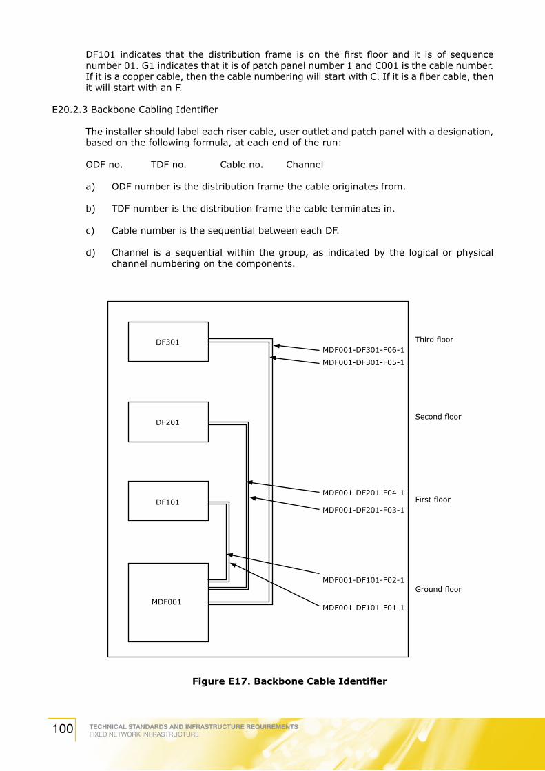
TECHNICAL STANDARDS AND INFRASTRUCTURE REQUIREMENTSFIXED NETWORK INFRASTRUCTURE100
DF101 indicates that the distribution frame is on the first floor and it is of sequence number 01. G1 indicates that it is of patch panel number 1 and C001 is the cable number. If it is a copper cable, then the cable numbering will start with C. If it is a fiber cable, then it will start with an F.
E20.2.3 Backbone Cabling Identifier
The installer should label each riser cable, user outlet and patch panel with a designation, based on the following formula, at each end of the run:
ODF no. TDF no. Cable no. Channel
a) ODF number is the distribution frame the cable originates from.
b) TDF number is the distribution frame the cable terminates in.
c) Cable number is the sequential between each DF.
d) Channel is a sequential within the group, as indicated by the logical or physical channel numbering on the components.
FigureE17.BackboneCableIdentifier
Third floorDF301
DF101
MDF001
DF201
MDF001-DF301-F06-1
MDF001-DF201-F04-1
MDF001-DF101-F02-1
MDF001-DF301-F05-1
MDF001-DF201-F03-1
MDF001-DF101-F01-1
Second floor
First floor
Ground floor

TECHNICAL STANDARDS AND INFRASTRUCTURE REQUIREMENTSFIXED NETWORK INFRASTRUCTURE 101
The above illustrates an example for a three storey building. The cable numbering should be MDF001-DF101-F01-1 to MDF001-DF301-F06-1, inclusive.
MDF001 indicates the originating distribution frame (a main distribution frame at ground floor), DF 101 indicates the distribution frame in which the cable terminates, F01 indicates the cable number (fiber optic, core number 1) and 1 indicates the patch panel in which the cable terminates in.
E20.2.4 Cable Labeling
Horizontal and backbone cable should be labelled at each end. The labels should be affixed at each end.
Additional labeling is required at each intermediate location such as conduit ends, backbone splice points, manholes and pull boxes.
Cables of different conductor counts that are spliced together are considered as separate cables.
Optionally, the different splice segments may be labeled with a single cable identifier provided that the pair/conductor count of the largest cable is maintained end-to-end and indicated on the cable labels.
If a cable is routed through multiple pathway segments, the pathway record linkage field should contain references to all pathway segments used.
E20.2.5 Termination Hardware Identifiers
An identifier should be marked on each of the termination hardware or its label.
E20.2.6 Termination Position Identifiers
A unique identifier should be assigned to each termination position to serve as a link to the termination position record.
E20.2.7 Termination Position Labeling
An identifier should be marked on each termination position label except in cases where high termination densities make labeling impractical.
In these cases, identifiers should be assigned to each termination hardware unit and to the actual termination position identifier determined by the conventions used for that unit.
E20.2.8 Splice Closure Identifiers and Labeling
A unique identifier should be assigned to each splice closure to serve as a link to the splice record.
An identifier should be marked on each splice closure or its label.
E20.3 Records
E20.3.1 Cable Records
The following items should be included in cable record:
a) cable identifier, cable type, un-terminated cable pair; b) damaged cable pair, available termination position record and

TECHNICAL STANDARDS AND INFRASTRUCTURE REQUIREMENTSFIXED NETWORK INFRASTRUCTURE102
c) splice record, pathway record, grounding record.
The cable type should include the manufacturer and manufacturer’s designation.
The termination position linkage field is used to record the termination positions of every pair/ conductor or set of pairs/conductors of the cable. Each pair/conductor or set of pairs/conductors has a linkage to two termination position records.
Table E26 illustrates the format for a cable record.
Table E26. Format for Cable Record
CABLE RECORDRECORD NO.
SAMPLE DATA COMMENTREQUIRED INFORMATIONCable Identifier Cable type Damaged cable pair Available cable pair
REQUIRED LINKAGES End 1 End 2
Pr 1, Term. Pos. RecordPr 2, Term. Pos. Record Pr 3, Term. Pos. RecordPr 4, Term. Pos. RecordPr 5, Term. Pos. Record Pr 6, Term. Pos. RecordSplice RecordGrounding Record
OPTIONAL INFORMATIONCable lengthUPCOwnershipMisc. Information
OTHER LINKAGES
Other record 1
E20.3.2 Termination Hardware Records
The termination hardware format should be as follows:
Table E27. Format for Termination Hardware Record
TERMINATION HARDWARE RECORD
RECORD NO:
SAMPLE DATA COMMENT
REQUIRED INFORMATION
Termination hardware identifier
Termination hardware type Damaged position nos.
REQUIRED LINKAGETerm. Pos. record 1

TECHNICAL STANDARDS AND INFRASTRUCTURE REQUIREMENTSFIXED NETWORK INFRASTRUCTURE 103
TERMINATION HARDWARE RECORDTerm. Pos. record 2Term. Pos. record 3Term. Pos. record 4Term. Pos. record 5Term. Pos. record 6Space record Grounding record
OPTIONAL INFORMATIONProtectionMisc. Information
OTHER LINKAGES Other record 1
E20.3.3 Termination Position Record
The following table illustrates the termination position record:
Table E28. Format for Termination Position Record
TERMINATION POSITION RECORDRECORD NO:
SAMPLE DATA COMMENTREQUIRED INFORMATIONTermination position identifierTermination position type User code Cable pr/cond. Numbers
REQUIRED LINKAGECable recordOther Term. Pos. record 1Other Term. Pos. record 2Other Term. Pos. record 3Term. Hardware recordSpace record
OPTIONAL INFORMATIONSignal carried Cross connect type End-end attenuationMisc. informationNEXT at Patch PanelNEXT at TO
OTHER LINKAGES Other record 1
Table E27. Format for Termination Hardware Record (continue)
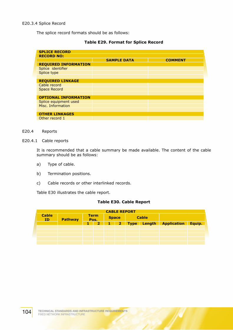
TECHNICAL STANDARDS AND INFRASTRUCTURE REQUIREMENTSFIXED NETWORK INFRASTRUCTURE104
E20.3.4 Splice Record
The splice record formats should be as follows:
Table E29. Format for Splice Record
SPLICE RECORDRECORD NO:
SAMPLE DATA COMMENTREQUIRED INFORMATIONSplice identifierSplice type
REQUIRED LINKAGECable record Space Record
OPTIONAL INFORMATIONSplice equipment used Misc. Information
OTHER LINKAGES Other record 1
E20.4 Reports
E20.4.1 Cable reports
It is recommended that a cable summary be made available. The content of the cable summary should be as follows:
a) Type of cable.
b) Termination positions.
c) Cable records or other interlinked records.
Table E30 illustrates the cable report.
Table E30. Cable Report
CABLE REPORTCable
ID PathwayTerm Pos. Space Cable
1 2 1 2 Type Length Application Equip.

TECHNICAL STANDARDS AND INFRASTRUCTURE REQUIREMENTSFIXED NETWORK INFRASTRUCTURE 105
Table E31. User Master Report
USER MASTER REPORT
User RoomData Cable Data Term. Data Net. ID Data Equip.
Tel. Cable Tel. Term Tel Ext./DEL Tel. Equip.
E20.4.2 End-To-End Circuit Reports
The end-to-end circuit report traces connectivity from end-to-end. It should list the following items:
a) User code
b) Associated termination positions
c) Cables connecting the work area to the other end of each circuit
Table E32. End-To-End Circuit Report
END-TO- END CIRCUIT REPORTUSER CODE TERM. POS. CABLE ID
E20.4.3 Cross-connect report
The table E33 illustrates the end-to-end circuit report. Each termination space containing cross-connects should have a cross connect report.
Table E33. Cross Connect Report
CROSS CONNECT REPORT
Space Cable ID Cross-Connect 1
Cross-Connect 2 Type
TECHNICAL STANDARDS AND INFRASTRUCTURE REQUIREMENTSFIXED NETWORK INFRASTRUCTURE106
E21. Labeling
E21.1 General
Labels may be divided into adhesive, insert and others.
E21.2 Adhesive Labels
Adhesive labels should meet the legibility, defacement and adhesion requirements specified in UL 969 (Ref. D-16). Labels should also meet the general exposure requirements in UL 969 for indoor use.
Care should be taken in choosing the material/ substrate designed for use on specific surface upon which the labels are to be applied. In harsh environments, sleeving or tags are more appropriate for the equipment surface.
Cable labels should have a durable substrate, such as vinyl, suitable for wrapping. Horizontal and backbone cables should be labeled at each end. It is recommended that the labels are affixed at each end rather than marking the cable.
E21.3 Insert Labels
Insert labels should meet the legibility, defacement and general exposure requirements specified in UL 969. An insert label should be securely held in place under the normal operating conditions and usage to which the labeled infrastructure elements are subjected.
E21.4 Other Labels
Other labels include special purpose labels that may use a different method of attachment, such as tie-on labels.
Labeling practices for all infrastructure elements should be consistent across an installation.
E21.5 Cable Labeling Rule
Cables of differing conductor counts that are spliced together may be administered as separate cables.
It is also preferred to have cable labeling on the cable at intermediate locations such as conduit ends, backbone splice points, manholes and pull boxes.
Horizontal and backbone cables should be labeled at each end. It is recommended that the labels are affixed at each end rather than marking the cable.

TECHNICAL STANDARDS AND INFRASTRUCTURE REQUIREMENTSFIXED NETWORK INFRASTRUCTURE 107
Acknowledgements
Listed below are the past and current contributors who were involved directly in the process of developing this Technical Standards and Infrastructure Requirements document:
Rosehaizad Abd Wahab (Chairman) Telekom Malaysia BerhadKamaruddin Nasir (Vice Chairman) TIME dotCom BerhadEncik Zulhairy Abdullah (Secretary) Telekom Malaysia BerhadEncik Michael Chew/ AMP Connectors Sdn BhdEncik Thomas Ko Encik Ravindran C. Panchan/ CableView Services Sdn Bhd (Mega TV)Encik Azmi Hj. Abd. Halim Encik Ramzi Abu Bakar Celcom (Malaysia) BerhadEncik Razuki Ibrahim/ Construction Industry Development Board Puan Zainora Zainal Malaysia (CIDB)Encik Guan Swee Teng Datacraft Malaysia Sdn BhdPuan Che Meriam Ismail Dewan Bandaraya Kuala LumpurEncik Karmegam Subramaniam Diamond Components Sdn BhdEncik Abdul Rashid Abu Bakar/ DiGi Telecommunications Sdn Bhd Encik Abd. Rashid Abu Bakar/ Encik Pua Chan Seng Encik Teoh Seng Long Fujikura Federal CableEncik Abu Fatah Sanusi Institution of Engineers MalaysiaEncik Madzlan Hashim Jabatan Bomba dan Penyelamat MalaysiaEncik Abdul Rahman Mohd Tasir Jabatan Kerja Raya MalaysiaEncik Seek Chee Keng Leader Universal OpticEncik Lim Chin Yam/ Malaysian National Computer ConfederationEncik Simon Kong Cik Tunku Azela/ Maxis Communications BerhadEncik Dave Ng/ Encik Govindaraju/ Encik Mohd Adib Jalaluddin Encik Ratnam N. A./ Measat Broadcast Network System Sdn BhdEncik Ooi Boon Wee Encik Sukumar Lechimanan Natseven TV Sdn Bhd (NTV7)Encik Chow Lai Yoon OrtronicsEncik Ahmad Faizan Pardi/ SIRIM BerhadPuan Nuriyati Ab Rahman Encik Yong Joon Fah Sistem Televisyen Malaysia Berhad (TV3)Encik Ahmad Mohd Salim/ Telekom Malaysia BerhadPuan Aida Jani/ Puan Anim Aris/ Puan Che Saniah Zakaria/ Puan Haliza Asha’ari/ Encik Kwok Peng Mun/ Encik Loh Tiew Kwee/ Encik Mohd Azmir Ramli/ Encik Mohd Jani Sarpon/ Encik Ronald Lim/ Rose Hayati Abd Halim/ Puan Sharliza Mohd Haris/ Encik Towfek Elias/ Encik Zambri Ismail Encik Ahmad Shahrim Bin Hj. Abd Rashid/ U Television Sdn Bhd (formerly known as MiTV Corporation Sdn Bhd)Encik Alvin Lee/ Encik Mustafa Kamal Bin MamatEncik Kuo Hai Ann Zettabits Technologies (M) Sdn Bhd
