ts 143 318 - v9.0.0 - digital cellular telecommunications system
TRANSCRIPT

ETSI TS 143 318 V9.0.0 (2010-02)
Technical Specification
Digital cellular telecommunications system (Phase 2+);Generic Access Network (GAN);
Stage 2 (3GPP TS 43.318 version 9.0.0 Release 9)
GLOBAL SYSTEM FOR MOBILE COMMUNICATIONS
R
ETSI
ETSI TS 143 318 V9.0.0 (2010-02)13GPP TS 43.318 version 9.0.0 Release 9
Reference RTS/TSGG-0143318v900
Keywords GSM
ETSI
650 Route des Lucioles F-06921 Sophia Antipolis Cedex - FRANCE
Tel.: +33 4 92 94 42 00 Fax: +33 4 93 65 47 16
Siret N° 348 623 562 00017 - NAF 742 C
Association à but non lucratif enregistrée à la Sous-Préfecture de Grasse (06) N° 7803/88
Important notice
Individual copies of the present document can be downloaded from: http://www.etsi.org
The present document may be made available in more than one electronic version or in print. In any case of existing or perceived difference in contents between such versions, the reference version is the Portable Document Format (PDF).
In case of dispute, the reference shall be the printing on ETSI printers of the PDF version kept on a specific network drive within ETSI Secretariat.
Users of the present document should be aware that the document may be subject to revision or change of status. Information on the current status of this and other ETSI documents is available at
http://portal.etsi.org/tb/status/status.asp
If you find errors in the present document, please send your comment to one of the following services: http://portal.etsi.org/chaircor/ETSI_support.asp
Copyright Notification
No part may be reproduced except as authorized by written permission. The copyright and the foregoing restriction extend to reproduction in all media.
© European Telecommunications Standards Institute 2010.
All rights reserved.
DECTTM, PLUGTESTSTM, UMTSTM, TIPHONTM, the TIPHON logo and the ETSI logo are Trade Marks of ETSI registered for the benefit of its Members.
3GPPTM is a Trade Mark of ETSI registered for the benefit of its Members and of the 3GPP Organizational Partners. LTE™ is a Trade Mark of ETSI currently being registered
for the benefit of its Members and of the 3GPP Organizational Partners. GSM® and the GSM logo are Trade Marks registered and owned by the GSM Association.
ETSI
ETSI TS 143 318 V9.0.0 (2010-02)23GPP TS 43.318 version 9.0.0 Release 9
Intellectual Property Rights IPRs essential or potentially essential to the present document may have been declared to ETSI. The information pertaining to these essential IPRs, if any, is publicly available for ETSI members and non-members, and can be found in ETSI SR 000 314: "Intellectual Property Rights (IPRs); Essential, or potentially Essential, IPRs notified to ETSI in respect of ETSI standards", which is available from the ETSI Secretariat. Latest updates are available on the ETSI Web server (http://webapp.etsi.org/IPR/home.asp).
Pursuant to the ETSI IPR Policy, no investigation, including IPR searches, has been carried out by ETSI. No guarantee can be given as to the existence of other IPRs not referenced in ETSI SR 000 314 (or the updates on the ETSI Web server) which are, or may be, or may become, essential to the present document.
Foreword This Technical Specification (TS) has been produced by ETSI 3rd Generation Partnership Project (3GPP).
The present document may refer to technical specifications or reports using their 3GPP identities, UMTS identities or GSM identities. These should be interpreted as being references to the corresponding ETSI deliverables.
The cross reference between GSM, UMTS, 3GPP and ETSI identities can be found under http://webapp.etsi.org/key/queryform.asp.

ETSI
ETSI TS 143 318 V9.0.0 (2010-02)33GPP TS 43.318 version 9.0.0 Release 9
Contents
Intellectual Property Rights ................................................................................................................................ 2
Foreword ............................................................................................................................................................. 2
Foreword ............................................................................................................................................................. 7
1 Scope ........................................................................................................................................................ 8
2 References ................................................................................................................................................ 8
3 Definitions, symbols and abbreviations ................................................................................................. 10
3.1 Definitions ........................................................................................................................................................ 10
3.2 Symbols ............................................................................................................................................................ 11
3.3 Abbreviations ................................................................................................................................................... 11
4 Architecture ............................................................................................................................................ 13
4.1 GAN A/Gb mode architecture .......................................................................................................................... 13
4.2 GAN Iu mode architecture ............................................................................................................................... 14
5 Functional entities .................................................................................................................................. 16
5.1 Mobile Station (MS) ......................................................................................................................................... 16
5.2 Generic Access Network Controller (GANC) .................................................................................................. 16
5.2.1 GAN A/Gb mode ........................................................................................................................................ 16
5.2.2 GAN Iu mode ............................................................................................................................................. 16
6 Control and User Plane Architecture ...................................................................................................... 17
6.1 CS Domain (GAN A/Gb mode) ....................................................................................................................... 17
6.1.1 CS Domain - Control Plane ........................................................................................................................ 17
6.1.1.1 CS Domain - Control Plane - GAN Architecture .................................................................................. 17
6.1.1.2 CS Domain - Control Plane - MS Architecture ..................................................................................... 18
6.1.2 CS Domain - User Plane ............................................................................................................................. 19
6.1.2.1 CS Domain - User Plane - GAN Architecture....................................................................................... 19
6.2 PS Domain (GAN A/Gb mode) ........................................................................................................................ 20
6.2.1 PS Domain - GAN Architecture ................................................................................................................. 20
6.2.1.1 PS Domain - Control Plane - GAN Architecture .................................................................................. 20
6.2.1.2 PS Domain - User Plane - GAN Architecture ....................................................................................... 21
6.2.2 PS Domain - MS Architecture .................................................................................................................... 22
6.3 CS Domain (GAN Iu mode) ............................................................................................................................. 23
6.3.1 CS Domain - Control Plane ........................................................................................................................ 23
6.3.1.1 CS Domain - Control Plane - GAN Architecture .................................................................................. 23
6.3.1.2 CS Domain - Control Plane - MS Architecture ..................................................................................... 24
6.3.2 CS Domain - User Plane ............................................................................................................................. 25
6.3.2.1 CS Domain - User Plane - GAN Architecture....................................................................................... 25
6.3.2.2 CS Domain - User Plane - MS Architecture ......................................................................................... 26
6.4 PS Domain (GAN Iu mode) ............................................................................................................................. 27
6.4.1 PS Domain - Control Plane ......................................................................................................................... 27
6.4.1.1 PS Domain - Control Plane - GAN Architecture .................................................................................. 27
6.4.1.2 PS Domain - Control Plane - MS Architecture ..................................................................................... 28
6.4.2 PS Domain - User Plane ............................................................................................................................. 29
6.4.2.1 PS Domain - User Plane - GAN Architecture ....................................................................................... 29
6.4.2.2 PS Domain - User Plane - MS Architecture .......................................................................................... 30
7 Management functionality ...................................................................................................................... 31
7.1 State diagram for Generic Access .................................................................................................................... 31
7.2 GA-RC (Generic Access Resource Control) .................................................................................................... 32
7.2.1 General ........................................................................................................................................................ 32
7.2.2 States of the GA-RC sub-layer ................................................................................................................... 32
7.3 GA-CSR (Generic Access Circuit Switched Resources) .................................................................................. 32
7.3.1 General ........................................................................................................................................................ 32
7.3.2 States of the GA-CSR sub-layer ................................................................................................................. 33

ETSI
ETSI TS 143 318 V9.0.0 (2010-02)43GPP TS 43.318 version 9.0.0 Release 9
7.4 GA-PSR (Generic Access Packet Switched Resources)................................................................................... 33
7.4.1 States of the GA-PSR sub-layer .................................................................................................................. 33
7.4a GA-RRC ........................................................................................................................................................... 34
7.4a.1 General ........................................................................................................................................................ 34
7.4a.2 States of the GA-RRC sub-layer ................................................................................................................. 34
7.5 Security Mechanisms ....................................................................................................................................... 35
8 High-Level Procedures for GAN A/Gb Mode ....................................................................................... 35
8.1 Mechanism of Mode Selection in Multi-mode terminals ................................................................................. 35
8.2 PLMN Selection ............................................................................................................................................... 36
8.3 Re-selection between GERAN/UTRAN and GAN modes ............................................................................... 37
8.3.1 Rove-in (from GERAN/UTRAN mode to GAN mode) ............................................................................. 37
8.3.2 Rove-out (from GAN mode to GERAN/UTRAN mode) ........................................................................... 38
8.4 GAN Discovery and Registration related procedures....................................................................................... 38
8.4.1 Discovery and Registration for Generic Access ......................................................................................... 38
8.4.1.1 General .................................................................................................................................................. 38
8.4.1.2 Security Gateway Identification ............................................................................................................ 38
8.4.1.3 GANC capabilities ................................................................................................................................ 39
8.4.1.4 MS capabilities ...................................................................................................................................... 39
8.4.1.4a Required GAN Services ........................................................................................................................ 39
8.4.1.4b GAN Mode Selection ............................................................................................................................ 39
8.4.1.5 Discovery Procedure ............................................................................................................................. 42
8.4.1.5.1 Normal Case .................................................................................................................................... 42
8.4.1.6 Registration procedure .......................................................................................................................... 43
8.4.1.6.1 Normal case ..................................................................................................................................... 43
8.4.1.6.2 Abnormal cases ............................................................................................................................... 45
8.4.2 De-Registration ........................................................................................................................................... 45
8.4.3 Registration Update .................................................................................................................................... 46
8.4.4 Keep Alive .................................................................................................................................................. 47
8.4.5 Cell Broadcast Information ......................................................................................................................... 47
8.5 Authentication .................................................................................................................................................. 48
8.6 Encryption ........................................................................................................................................................ 48
8.6.1 Establishment of a Secure Association ....................................................................................................... 48
8.7 GA-CSR Connection handling ......................................................................................................................... 49
8.7.1 GA-CSR Connection Establishment ........................................................................................................... 49
8.7.2 GA-CSR Connection Release ..................................................................................................................... 49
8.8 Ciphering Configuration ................................................................................................................................... 50
8.9 GA-CSR Signalling and SMS Transport Procedures ....................................................................................... 50
8.9.1 Network initiated CS Signalling ................................................................................................................. 50
8.9.2 MS initiated CS Signalling ......................................................................................................................... 51
8.10 Mobile Originated Call Flow............................................................................................................................ 51
8.11 Mobile Terminated Call Flow .......................................................................................................................... 53
8.12 Call Clearing .................................................................................................................................................... 54
8.13 Channel Modify .......................................................................................................................................... 54
8.14 CS Handover between GAN A/Gb mode and GERAN/UTRAN mode ........................................................... 55
8.14.1 CS Handover to GAN A/Gb mode ............................................................................................................. 55
8.14.1.1 GERAN to GAN CS Handover ............................................................................................................. 55
8.14.1.2 UTRAN to GAN CS Handover ............................................................................................................. 57
8.14.2 CS Handover from GAN A/Gb mode to GERAN ...................................................................................... 59
8.14.3 CS Handover from GAN A/Gb mode to UTRAN ...................................................................................... 61
8.15 Cell Change Order between GAN A/Gb mode and GERAN/UTRAN mode .................................................. 62
8.16 GA-PSR Transport Channel Management Procedures ..................................................................................... 63
8.16.1 MS initiated Activation of GA-PSR Transport Channel ............................................................................. 63
8.16.2 MS initiated Deactivation of the GA-PSR Transport Channel ................................................................... 64
8.16.3 Implicit Deactivation of the GA-PSR Transport Channel due to MS Deregistration ................................. 65
8.16.4 Network initiated GA-PSR Transport Channel Activation ......................................................................... 65
8.17 GPRS Data, Signalling and SMS Transport ..................................................................................................... 66
8.17.1 GA-PSR GPRS Data Transport Procedures ................................................................................................ 66
8.17.2 GA-PSR GPRS Signalling and SMS Transport Procedures ....................................................................... 66
8.17.2.1 General .................................................................................................................................................. 66
8.17.2.2 Network initiated GPRS Signalling ...................................................................................................... 67
8.17.2.3 MS initiated GPRS Signalling............................................................................................................... 67

ETSI
ETSI TS 143 318 V9.0.0 (2010-02)53GPP TS 43.318 version 9.0.0 Release 9
8.18 GA-PSR Specific Signalling Procedures .......................................................................................................... 67
8.18.1 Packet Paging for GPRS Data Service ........................................................................................................ 67
8.18.2 Packet Paging for CS Domain Service ....................................................................................................... 68
8.18.3 GPRS Suspend Procedure ........................................................................................................................... 68
8.18.4 GPRS Resume Procedure ........................................................................................................................... 69
8.18.5 MS Initiated Downlink Flow Control ......................................................................................................... 70
8.18.6 Uplink Flow Control ................................................................................................................................... 71
8.19 Short Message Service ..................................................................................................................................... 71
8.19.1 GSM based SMS ......................................................................................................................................... 71
8.19.2 GPRS based SMS ....................................................................................................................................... 72
8.20 Supplementary Services ................................................................................................................................... 72
8.21 Emergency Services ......................................................................................................................................... 72
8.21.1 General ........................................................................................................................................................ 72
8.21.2 North American Emergency Calls .............................................................................................................. 72
8.21.2.1 Phase 1 Solution .................................................................................................................................... 72
8.21.2.1.1 Phase 1 Requirements ...................................................................................................................... 72
8.21.2.1.2 Phase 1 Mechanism ......................................................................................................................... 73
8.21.2.2 Phase 2 Solution .................................................................................................................................... 73
8.21.2.2.1 Phase 2 Requirements ...................................................................................................................... 73
8.21.2.2.2 Phase 2 Mechanism ......................................................................................................................... 73
8.22 Location Services ............................................................................................................................................. 73
8.23 PS Handovers between GAN A/Gb mode and GERAN/UTRAN mode .......................................................... 74
9 High-Level Procedures for GAN Iu Mode ............................................................................................. 74
9.1 Mechanism of Mode Selection in Multi-mode terminals ................................................................................. 74
9.2 PLMN Selection ............................................................................................................................................... 74
9.3 Re-selection between GERAN/UTRAN and GAN modes ............................................................................... 74
9.4 GAN Discovery and Registration related procedures....................................................................................... 74
9.5 Authentication .................................................................................................................................................. 74
9.6 Encryption ........................................................................................................................................................ 74
9.7 GA-RRC Connection handling......................................................................................................................... 74
9.7.1 GA-RRC Connection Establishment .......................................................................................................... 75
9.7.2 GA-RRC Connection Release..................................................................................................................... 75
9.7.3 GA-RRC Connection Release Request ....................................................................................................... 76
9.8 Security Mode Control ..................................................................................................................................... 76
9.9 NAS Signalling Procedures .............................................................................................................................. 77
9.10 Mobile Originated CS Call ............................................................................................................................... 78
9.11 Mobile Terminated CS Call.............................................................................................................................. 80
9.12 CS Call Clearing ............................................................................................................................................... 82
9.12.1 CS Call Release .......................................................................................................................................... 82
9.12.2 CS Channel Release .................................................................................................................................... 82
9.13 CS Channel Modification ................................................................................................................................. 83
9.14 CS Handover between GAN Iu mode and GERAN/UTRAN mode ................................................................ 84
9.14.1 CS Handover from GERAN to GAN ..................................................................................................................... 84
9.14.1.1 Normal case: IMSI is present in Relocation Request message ............................................................. 85
9.14.1.2 Exception Case: No IMSI in Relocation Request ................................................................................. 87
9.14.2 CS Handover from UTRAN to GAN .......................................................................................................... 88
9.14.2.1 Normal Case: IMSI is present in Relocation Request message ............................................................. 89
9.14.2.2 Exception Case: No IMSI in Relocation Request ................................................................................. 90
9.14.3 CS Handover from GAN Iu mode to GERAN ........................................................................................... 91
9.14.4 CS Handover from GAN Iu mode to UTRAN ........................................................................................... 93
9.15 Cell Change Order between GAN Iu mode and GERAN mode ....................................................................... 95
9.16 GA-RRC Packet Transport Channel Management Procedures ........................................................................ 95
9.16.1 States of the GA-RRC Packet Transport Channel ...................................................................................... 96
9.16.2 PTC Activation ........................................................................................................................................... 96
9.16.2.1 PTC Activation when GANC receives RAB Assignment Request ....................................................... 96
9.16.2.2 PTC Activation when GANC receives Relocation Request .................................................................. 98
9.16.3 PTC Data transfer ....................................................................................................................................... 99
9.16.4 MS initiated PTC De-activation.................................................................................................................. 99
9.16.5 MS initiated PTC Re-activation ................................................................................................................ 100
9.16.6 Network initiated PTC De-activation ....................................................................................................... 101
9.16.7 Network initiated PTC Re-activation ........................................................................................................ 102

ETSI
ETSI TS 143 318 V9.0.0 (2010-02)63GPP TS 43.318 version 9.0.0 Release 9
9.16.7.1 Active PDP Context, PS Signalling Connection Exists ...................................................................... 102
9.16.7.2 Active PDP Context, No PS Signalling Connection ........................................................................... 103
9.16.8 Implicit PTC De-activation due to MS De-registration ............................................................................ 104
9.16.9 PTC Modification ..................................................................................................................................... 104
9.17 (void) .............................................................................................................................................................. 105
9.18 (void) .............................................................................................................................................................. 105
9.19 Short Message Service ................................................................................................................................... 105
9.19.1 SMS via the CS domain ............................................................................................................................ 105
9.19.2 SMS via the PS domain ............................................................................................................................ 105
9.20 Supplementary Services ................................................................................................................................. 106
9.21 Emergency Services ....................................................................................................................................... 106
9.22 Location Services ........................................................................................................................................... 106
9.23 PS Handover between GAN Iu mode and GERAN/UTRAN mode ............................................................... 106
9.23.1 PS Handover from GERAN to GAN ........................................................................................................ 106
9.23.1.1 Preparation Phase ................................................................................................................................ 106
9.23.1.2 Execution Phase .................................................................................................................................. 107
9.23.2 PS Handover from UTRAN to GAN ........................................................................................................ 108
9.23.2.1 Preparation Phase ................................................................................................................................ 108
9.23.2.2 Execution Phase .................................................................................................................................. 110
9.23.3 PS Handover from GAN to GERAN ........................................................................................................ 111
9.23.3.1 Preparation Phase ................................................................................................................................ 111
9.23.3.2 Execution Phase .................................................................................................................................. 112
9.23.4 PS handover from GAN to UTRAN ......................................................................................................... 113
9.23.4.1 Preparation Phase ................................................................................................................................ 113
9.23.4.2 Execution Phase .................................................................................................................................. 114
Annex A (normative): Security mechanisms ................................................................................... 115
A.1 EAP based Authentication.................................................................................................................... 115
A.1.1 EAP-SIM Procedure for authentication .......................................................................................................... 115
A.1.2 EAP-AKA Procedure for authentication ........................................................................................................ 117
A.1.3 Fast Re-authentication .................................................................................................................................... 118
A.1.3.1 EAP-SIM Fast Re-authentication ............................................................................................................. 119
A.1.3.2 EAP-AKA Fast Re-authentication ............................................................................................................ 120
A.2 Profile of IKEv2 ................................................................................................................................... 121
A.3 Profile of IPsec ESP ............................................................................................................................. 121
Annex B (informative): Configuration Information ......................................................................... 123
B.1 GAN A/Gb mode ARFCN/BSIC for handover-to-GAN ..................................................................... 123
B.2 GAN Iu mode UARFCN/PSC for handover-to-GAN .......................................................................... 123
B.2.1 Cell Measurement Quantities and Values ...................................................................................................... 123
Annex C (informative): Identifiers in GAN ...................................................................................... 124
C.1 Identifiers for MSs and generic IP access network .............................................................................. 124
C.2 Cell identifiers for GAN A/Gb mode ................................................................................................... 124
C.2.1 GAN Cell Id for Location Services & Billing ................................................................................................ 124
C.2.1.1 Assigning GAN Cell Id based on GSM location ...................................................................................... 124
C.2.2 GAN Cell Id for handover-to-GAN ............................................................................................................... 125
C.2.3 GAN ARFCN/BSIC for handover-to-GAN ................................................................................................... 125
C.3 (void) .............................................................................................................................................................. 125
Annex D (informative): Change history ............................................................................................. 126
History ............................................................................................................................................................ 127

ETSI
ETSI TS 143 318 V9.0.0 (2010-02)73GPP TS 43.318 version 9.0.0 Release 9
Foreword This Technical Specification has been produced by the 3rd Generation Partnership Project (3GPP).
The contents of the present document are subject to continuing work within the TSG and may change following formal TSG approval. Should the TSG modify the contents of the present document, it will be re-released by the TSG with an identifying change of release date and an increase in version number as follows:
Version x.y.z
where:
x the first digit:
1 presented to TSG for information;
2 presented to TSG for approval;
3 or greater indicates TSG approved document under change control.
y the second digit is incremented for all changes of substance, i.e. technical enhancements, corrections, updates, etc.
z the third digit is incremented when editorial only changes have been incorporated in the document.

ETSI
ETSI TS 143 318 V9.0.0 (2010-02)83GPP TS 43.318 version 9.0.0 Release 9
1 Scope The present document defines the stage 2 service description for a Generic Access Network (GAN) . It describes the GAN system concepts, documents the reference architecture, functional entities, network interfaces, and high-level procedures.
GAN supports two modes of operation:
• GAN A/Gb mode
• GAN Iu mode
GAN A/Gb mode supports an extension of GSM/GPRS mobile services that is achieved by tunnelling Non Access Stratum (NAS) protocols between the MS and the Core Network over an IP network and the A and Gb interfaces to the MSC and SGSN, respectively.
GAN Iu mode supports an extension of UMTS mobile services that is achieved by tunnelling Non Access Stratum (NAS) protocols between the user equipment (MS) and the Core Network over an IP network and the Iu-cs and Iu-ps interfaces to the MSC and SGSN, respectively.
Both GAN modes are complements to traditional GSM/GPRS/UMTS radio access network coverage.
2 References The following documents contain provisions which, through reference in this text, constitute provisions of the present document.
• References are either specific (identified by date of publication, edition number, version number, etc.) or non-specific.
• For a specific reference, subsequent revisions do not apply.
• For a non-specific reference, the latest version applies. In the case of a reference to a 3GPP document (including a GSM document), a non-specific reference implicitly refers to the latest version of that document in the same Release as the present document.
[1] 3GPP TS 23.002: "Network architecture".
[2] 3GPP TS 23.009: "Handover procedures".
[3] 3GPP TS 23.271: "Location Services (LCS); Functional description; Stage 2".
[4] 3GPP TS 23.122: "Non-Access-Stratum functions related to Mobile Station (MS) in idle mode".
[5] 3GPP TS 23.236: "Intra-domain connection of Radio Access Network (RAN) nodes to multiple Core Network (CN) nodes".
[6] 3GPP TS 24.008: "Mobile radio interface layer 3 specification; Core network protocols; Stage 3".
[7] 3GPP TS 26.071: "AMR speech codec; General description".
[8] 3GPP TS 29.234: "3GPP system to Wireless Local Area Network (WLAN) interworking, Stage 3".
[9] 3GPP TS 33.234: "3G security; Wireless Local Area Network (WLAN) interworking security".
[10] 3GPP TS 43.020: "Security related network functions".
[11] 3GPP TS 48.004: "Base Station System - Mobile-services Switching Centre (BSS-MSC) interface; Layer 1 specification".

ETSI
ETSI TS 143 318 V9.0.0 (2010-02)93GPP TS 43.318 version 9.0.0 Release 9
[12] 3GPP TS 48.006: "Signalling transport mechanism specification for the Base Station System - Mobile-services Switching Centre (BSS-MSC) interface".
[13] 3GPP TS 48.008: "Mobile Switching Centre - Base Station System (MSC-BSS) interface; Layer 3 specification".
[14] 3GPP TS 48.014: "General Packet Radio Service (GPRS); Base Station System (BSS) - Serving GPRS Support Node (SGSN) interface; Gb interface Layer 1".
[15] 3GPP TS 48.016: "General Packet Radio Service (GPRS); Base Station System (BSS) - Serving GPRS Support Node (SGSN) interface; Network Service".
[16] 3GPP TS 48.018: "General Packet Radio Service (GPRS); Base Station System (BSS) - Serving GPRS Support Node (SGSN) interface; BSS GPRS protocol".
[17] 3GPP TS 43.059: "Functional stage 2 description of Location Services (LCS) in GERAN".
[18] 3GPP TS 45.008: "Radio subsystem link control".
[19] IETF RFC 793: "Transmission Control Protocol".
[20] IETF RFC 3550: "RTP: A Transport Protocol for Real-Time Applications".
[21] IETF RFC 2451: "The ESP CBC-Mode Cipher Algorithms".
[22] IETF RFC 3602: "The AES-CBC Cipher Algorithm and Its Use with IPsec".
[23] IETF RFC 2104: "HMAC: Keyed-Hashing for Message Authentication".
[24] IETF RFC 2315: "PKCS #7: Cryptographic Message Syntax Version 1.5".
[25] IETF RFC 2404: "The Use of HMAC-SHA-1-96 within ESP and AH".
[26] IETF RFC 2406: "IP Encapsulating Security Payload (ESP)".
[27] IETF RFC 3566: "The AES-XCBC-MAC-96 Algorithm and Its Use With IPsec".
[28] IETF RFC 4434, February 2006: "The AES-XCBC-PRF-128 Algorithm for the Internet Key Exchange Protocol (IKE)".
[29] IETF RFC 3280: "Internet X.509 Public Key Infrastructure Certificate and Certificate Revocation List (CRL) Profile".
[30] IETF draft-haverinen-pppext-eap-sim-16 (December 2004): "Extensible Authentication Protocol Method for GSM Subscriber Identity Modules (EAP-SIM)".
[31] IETF draft-ietf-pki4ipsec-ikecert-profile-03 (October 2004): "The Internet IP Security PKI Profile of IKEv1/ISAKMP, IKEv2, and PKIX".
[32] IETF draft-ietf-ipsec-ikev2-17 (October 2004): "Internet Key Exchange (IKEv2) Protocol".
[33] IETF draft-ietf-ipsec-ikev2-algorithms-05 (April 2004): "Cryptographic Algorithms for use in the Internet Key Exchange Version 2".
[34] IETF draft-ietf-ipsec-ui-suites-06 (April 2004): "Cryptographic Suites for IPsec".
[35] IETF RFC 3948: "UDP Encapsulation of IPsec ESP Packets".
[36] IETF RFC 2486: "The Network Access Identifier".
[37] IETF RFC 768: "User Datagram Protocol".
[38] IETF draft-arkko-pppext-eap-aka-15 (December 2004): "Extensible Authentication Protocol Method for 3rd Generation Authentication and Key Agreement (EAP-AKA)".
[39] IETF RFC 791: "Internet Protocol".
[40] 3GPP TS 25.331: "Radio Resource Control (RRC) protocol specification".

ETSI
ETSI TS 143 318 V9.0.0 (2010-02)103GPP TS 43.318 version 9.0.0 Release 9
[41] 3GPP TS 23.032: "Universal Geographical Area Description (GAD)".
[42] IETF RFC 2409: "The Internet Key Exchange (IKE)".
[43] 3GPP TS 23.003: "Numbering, addressing and identification".
[44] 3GPP TS 43.129: " Packet-switched handover for GERAN A/Gb mode; Stage 2'.
[45] 3GPP TS 25.410: "UTRAN Iu Interface: general aspects and principles".
[46] 3GPP TS 25.411: "UTRAN Iu interface layer 1".
[47] 3GPP TS 25.412: "UTRAN Iu interface signalling transport".
[48] 3GPP TS 25.413: "UTRAN Iu interface Radio Access Network Application Part (RANAP) signalling".
[49] 3GPP TS 25.414: "UTRAN Iu interface data transport & transport signalling".
[50] 3GPP TS 25.415: "UTRAN Iu interface user plane protocols".
[51] 3GPP TS 25.419: "UTRAN Iu-BC interface: Service Area Broadcast Protocol (SABP)".
[52] 3GPP TS 25.450: "UTRAN Iupc interface general aspects and principles".
[53] 3GPP TS 22.011: "Service accessibility".
3 Definitions, symbols and abbreviations
3.1 Definitions For the purposes of the present document, the following terms and definitions apply:
AP-ID: The AP-ID (Access Point-ID) is the physical identity (e.g. MAC address) of the generic IP access network point through which the MS is accessing GAN service. This identifier is provided by the MS (obtained via broadcast from the AP) to the GANC via the Up interface, when it requests GAN service. The AP-ID may be used by the GANC to support location services. The AP-ID may also be used by the service provider to restrict GAN service access via only authorized APs.
GERAN/UTRAN Mode: MS mode of operation where the NAS layers communicate through either the GERAN RR or the UTRAN RRC entities.
GAN A/Gb Mode: MS mode of operation where the NAS layers communicate through the GA-CSR and GA-PSR entities.
GAN Iu Mode: MS mode of operation where the NAS layers communicate through the GA-RRC CS and GA-RRC PS entities.
GAN Mode: This term is used when a procedure applies to both GAN A/Gb mode and GAN Iu mode (e.g., see clause 8.1, 'Mechanism of Mode Selection in Multi-mode terminals').
Generic Access Network: access network providing access to A/Gb or Iu interfaces via an IP network
Generic Access Network Controller: network node that connects to the MSC and SGSN via the A-interface and Gb interface (GAN A/Gb mode) or the Iu-cs interface and Iu-ps interface (GAN Iu mode) and enables access via a generic IP network. Three different logical roles for the GANC are defined in this specification: Provisioning GANC, Default GANC and Serving GANC.
default GANC: logical role of a GANC in the HPLMN, which redirects an MS performing the GAN Registration Procedure to a preferred Serving GANC within the HPLMN or VPLMN. The Serving GANC and Default GANC may be the same entity, in which case no redirection is required.

ETSI
ETSI TS 143 318 V9.0.0 (2010-02)113GPP TS 43.318 version 9.0.0 Release 9
discovery procedure: process by which the MS discovers the Default GANC in the HPLMN.
CS handover: mobile station engaged in a call (a CS domain service) moves between 3GPP access networks and GAN.
handover in: mobile station moves from 3GPP access networks to GAN.
handover out: mobile station moves from GAN to 3GPP access networks.
PS handover: A mobile station with one or more ongoing PS domain services moves between a GAN cell and a GERAN/UTRAN cell.
provisioning GANC: logical role of a GANC in the HPLMN of an MS. When an MS performs the Discovery Procedure to this GANC, the MS is provided the address of the Default GANC in the HPLMN.
redirection: process by which a Default or Serving GANC redirects an MS to an alternative Serving GANC This alternative GANC is likely to become the Serving GANC for the MS.
registration procedure: process by which an MS requests the Generic Access Service from a GANC.
rove in: mobile station reselects from 3GPP access networks to GAN.
rove out: mobile station reselects from GAN to 3GPP access networks.
roving: action of re-selection between 3GPP access technology and GAN for a mobile station in idle mode.
seamless: free from noticeable transitions (i.e. no end-user action is required; speech interruptions are short; service interruptions are short; incoming calls are not missed; packet sessions are maintained; services work identically).
serving GANC: logical role of the GANC in a PLMN which provides an MS with the Generic Access service.
suitable cell: this is a cell on which an MS may camp. It must satisfy criteria which are defined for A/Gb mode in 3GPP TS 43.022 and for Iu mode in 3GPP TS 25.304.
user equipment: generally referred to as 'mobile station' in this document.
3.2 Symbols For the purposes of the present document, the following symbols apply:
Up Interface between MS and GANC
3.3 Abbreviations For the purposes of the present document, the following abbreviations apply:
AAA Authentication, Authorization and Accounting AKA Authentication and Key Agreement AP Access Point AS Access Stratum BSC Base Station Controller BSS Base Station Subsystem BSSGP Base Station System GPRS Protocol BSSMAP Base Station System Management Application Part CC Call Control CGI Cell Global Identification CM Connection Management CN Core Network CS Circuit Switched CTM Cellular Text Telephone Modem DNS Domain Name System DTM Dual Transfer Mode EAP Extensible Authentication Protocol ETSI European Telecommunications Standards Institute

ETSI
ETSI TS 143 318 V9.0.0 (2010-02)123GPP TS 43.318 version 9.0.0 Release 9
FCC US Federal Communications Commission FQDN Fully Qualified Domain Name GA-CSR Generic Access - Circuit Switched Resources GAD Geographical Area Description GAN Generic Access Network GANC Generic Access Network Controller GA-PSR Generic Access - Packet Switched Resources GA-RC Generic Access - Resource Control GA-RRC Generic Access - Radio Resource Control GERAN GSM EDGE Radio Access Network GGSN Gateway GPRS Support Node GMM/SM GPRS Mobility Management and Session Management GPRS General Packet Radio Service GSM Global System for Mobile communications GSN GPRS Support Node HLR Home Location Register HPLMN Home PLMN IETF Internet Engineering Task Force IKE Internet Key Exchange IMEISV International Mobile station Equipment Identity and Software Version number IMSI International Mobile Subscriber Identity IP Internet Protocol LA Location Area LAI Location Area Identity LLC Logical Link Control MAC Medium Access Control MAC Message Authentication Code MM Mobility Management MS Mobile Station MSC Mobile Switching Center MTP1 Message Transfer Part layer 1 MTP2 Message Transfer Part layer 2 MTP3 Message Transfer Part layer 3 NAS Non-Access Stratum PDP Packet Data Protocol PDU Protocol Data Unit PLMN Public Land Mobile Network PS Packet Switched PSAP Public Safety Answering Point
NOTE: A PSAP is an emergency services network element that is responsible for answering emergency calls.
PSTN Public Switched Telephone Network P-TMSI Packet - TMSI QoS Quality of Service RA Routing Area RAC Routing Area Code RAI Routing Area Identity RAT Radio Access Technology RLC Radio Link Control RNC Radio Network Controller RTCP Real Time Control Protocol RTP Real Time Protocol SCCP Signalling Connection Control Part SEGW SEcurity GateWay SGSN Serving GPRS Support Node SIM Subscriber Identity Module SMLC Serving Mobile Location Center SMS Short Message Service SNDCP Sub-Network Dependent Convergence Protocol TBF Temporary Block Flow TC Transport Channel

ETSI
ETSI TS 143 318 V9.0.0 (2010-02)133GPP TS 43.318 version 9.0.0 Release 9
TCP Transmission Control Protocol TFO Tandem Free Operation TMSI Temporary Mobile Subscriber Identity TrFO Transcoder Free Operation TTY Text Telephone or TeletYpewriter UDP User Datagram Protocol UE User Equipment UMTS Universal Mobile Telecommunication System VLR Visited Location Register VPLMN Visited Public Land Mobile Network
4 Architecture
4.1 GAN A/Gb mode architecture The Generic Access Network A/Gb mode functional architecture is illustrated in figure 1.
MSGeneric IP
Access Network
MSC
SGSN
U p Gb
A
Generic Access Network
Controller(GANC)
Out of Scope
AAA Proxy/ Server
Wm
SEGW
Wd
HLR D’ / Gr ’
HPLMN (roaming case)
MS Mobile StationGANC GAN ControllerSEGW Security Gateway
HPLMN/VPLMN
CBC
MSGeneric IP
Access Network
MSC
SGSN
U p Gb
A
Generic Access Network
Controller(GANC)
Out of Scope
AAA Proxy/ Server
Wm
SEGW
Wd
HLR D’ / Gr ’
HPLMN (roaming case)
MS Mobile StationGANC GAN ControllerSEGW Security Gateway
HPLMN/VPLMN
Lb
SMLC
Figure 1: GAN A/Gb mode functional architecture
The main features of the GAN A/Gb mode architecture are:
• New entities, and entities with enhanced functionality:
- Mobile Station (MS).
- Generic Access Network Controller (GANC). The GANC appears to the core network as a GERAN Base Station Subsystem (BSS). It includes a Security Gateway (SEGW) that terminates secure remote access tunnels from the MS, providing mutual authentication, encryption and data integrity for signalling, voice and data traffic.
• A Generic IP Access network provides connectivity between the MS and the GANC. The IP transport connection extends from the GANC to the MS. A single interface, the Up interface, is defined between the GANC and the MS.
ETSI
ETSI TS 143 318 V9.0.0 (2010-02)143GPP TS 43.318 version 9.0.0 Release 9
• Co-existence with the GSM/GPRS Radio Access Network (GERAN) and interconnection with the Core Network (CN) via the standardized interfaces defined for GERAN A/Gb mode:
- A-interface for circuit switched services as defined in 3GPP TS 48.008 [13].
- Gb-interface for packet switched services as defined in 3GPP TS 48.018 [16].
- Lb-interface for supporting location services as defined in 3GPP TS 43.059 [17].
- CBC-BSC interface for supporting cell broadcast services as defined in 3GPP TS 23.041
• Transaction control (e.g. CC, SM) and user services are provided by the core network (e.g. MSC/VLR and the SGSN/GGSN).
• Use of AAA server over the Wm interface as defined by 3GPP TS 29.234 [8]. The AAA server is used to authenticate the MS when it sets up a secure tunnel. Note that only a subset of the Wm functionalities is required for the GAN application. As a minimum the GANC-SEGW shall support the Wm authentication procedures.
Indication of support for PS Services and of support for DTM is provided through appropriate signalling to the MS.
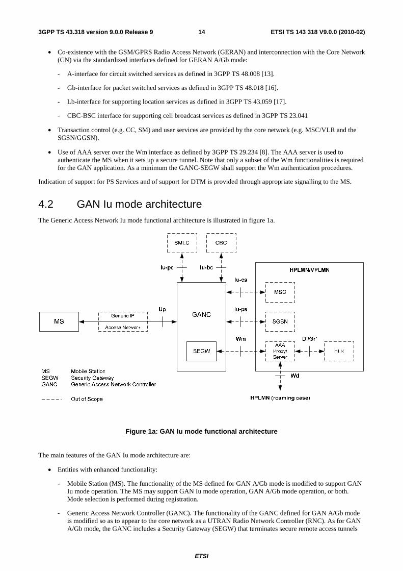
4.2 GAN Iu mode architecture The Generic Access Network Iu mode functional architecture is illustrated in figure 1a.
Figure 1a: GAN Iu mode functional architecture
The main features of the GAN Iu mode architecture are:
• Entities with enhanced functionality:
- Mobile Station (MS). The functionality of the MS defined for GAN A/Gb mode is modified to support GAN Iu mode operation. The MS may support GAN Iu mode operation, GAN A/Gb mode operation, or both. Mode selection is performed during registration.
- Generic Access Network Controller (GANC). The functionality of the GANC defined for GAN A/Gb mode is modified so as to appear to the core network as a UTRAN Radio Network Controller (RNC). As for GAN A/Gb mode, the GANC includes a Security Gateway (SEGW) that terminates secure remote access tunnels

ETSI
ETSI TS 143 318 V9.0.0 (2010-02)153GPP TS 43.318 version 9.0.0 Release 9
from the MS, providing mutual authentication, encryption and data integrity for signalling, voice and data traffic.
• A generic IP access network provides connectivity between the MS and the GANC. The IP transport connection extends from the GANC to the MS. A single interface, the Up interface, is defined between the GANC and the MS. Functionality is added to this interface, over that defined for GAN A/Gb mode, to support the GAN Iu mode service.
• Co-existence with the UMTS Terrestrial Radio Access Network (UTRAN) and interconnection with the Core Network (CN) via the standardized interfaces defined for UTRAN:
- Iu-cs interface for circuit switched services as overviewed in 3GPP TS 25.410 [45].
- Iu-ps interface for packet switched services as overviewed in 3GPP TS 25.410 [45].
- Iu-pc interface for supporting location services as described in 3GPP TS 25.450 [52].
- Iu-bc interface for supporting cell broadcast services as described in 3GPP TS 25.419 [51].
• Transaction control (e.g. CC, SM) and user services are provided by the core network (e.g. MSC/VLR and the SGSN/GGSN).
• Use of AAA server over the Wm interface as defined by 3GPP TS 29.234 [8]. The AAA server is used to authenticate the MS when it sets up a secure tunnel. Note that only a subset of the Wm functionalities is required for GAN Iu mode. As a minimum the GANC-SEGW shall support the Wm authentication procedures.
A GANC implementation may simultaneously support both GAN A/Gb mode and GAN Iu mode operation; the interfaces associated with both modes of operation are shown in the following figure.
Figure 1b: Simultaneous GAN A/Gb mode and GAN Iu mode functional architecture

ETSI
ETSI TS 143 318 V9.0.0 (2010-02)163GPP TS 43.318 version 9.0.0 Release 9
5 Functional entities
5.1 Mobile Station (MS) The MS contains a new functional block to access a Generic Access Network (GAN).
5.2 Generic Access Network Controller (GANC)
5.2.1 GAN A/Gb mode
The core network interacts with the Generic Access Network Controller (GANC) as though it was an A/Gb mode BSS. The generic IP access network provides connectivity between the GANC and the MS. The GANC entity inter-works between the A/Gb interfaces and a generic IP access network, using the following functionality:
• User plane circuit switched services:
- Reframing of AMR/RTP to AMR/(A-interface framing).
- If non-TrFO, transcoding voice to/from the MS to PCM voice from/to the MSC.
- If TrFO, transcoding maybe required if a common codec cannot be negotiated.
• User plane packet switched services:
- Inter-working data transport channels over Up interface to packet flows over Gb interface.
• Control plane functionality:
- Security Gateway (SEGW) for the set-up of a secure tunnel to MS for mutual authentication, encryption and data integrity. The SEGW provides a subset of the Wm functions, specifically the authentication procedures.
- Registration for GAN access and providing system information.
- Management of GAN bearer paths for CS and PS services, including the establishment, administration, and release of control and user plane bearers between the MS and the GANC.
- Functionality providing support for paging, handover and PS handover procedures.
- Transparent transfer of L3 messages (i.e. NAS protocols) between the MS and core network.
5.2.2 GAN Iu mode
The core network interacts with the Generic Access Network Controller (GANC) as though it was an RNC. The generic IP access network provides connectivity between the GANC and the MS. The GANC entity inter-works between the Iu interfaces and a generic IP access network, using the following functionality:
• User plane circuit switched services:
- The interworking of circuit switched user data between the Up interface and the Iu-cs interface
• User plane packet switched services:
- The interworking of packet switched user data between the Up interface and the Iu-ps interface

ETSI
ETSI TS 143 318 V9.0.0 (2010-02)173GPP TS 43.318 version 9.0.0 Release 9
• Control plane functionality:
- Security Gateway (SEGW) for the set-up of a secure tunnel to the MS for mutual authentication, encryption and data integrity
- GAN Discovery support and Default GANC assignment
- GAN Registration support including provision of GAN system information to the MS and possible redirection to a different Serving GANC
- Management of GAN bearer paths for CS and PS services, including the establishment, administration, and release of control and user plane bearers between the MS and the GANC
- Functionality providing support for paging and relocation/handover procedures
- Transparent transfer of L3 messages (i.e., NAS protocols) between the MS and core network
6 Control and User Plane Architecture
6.1 CS Domain (GAN A/Gb mode)
6.1.1 CS Domain - Control Plane
6.1.1.1 CS Domain - Control Plane - GAN Architecture
The GAN architecture in support of CS Domain control plane is illustrated in figure 2.
GANC MS
SCCP SCCP
MTP3
A
MM MM
Transport IP MTP2
MTP1
MTP3
MTP1
Up Interface
Access Layers
Transport IP Transport IP
CC/SS/SMS
Access Layers
Generic IP Network
BSSAP
Remote IP
MSC
A
BSSAP
Access Layers
MTP2
CC/SS/SMS
Remote IP IPSec ESP IPSec ESP
TCP
GA-RC
GA-CSR
TCP
GA-CSR
GA-RC
Figure 2: Up CS Domain Control Plane Architecture
The main features of the Up interface for the CS domain control plane are as follows:
• The underlying Access Layers and Transport IP layer provides the generic connectivity between the MS and the GANC.
• The IPsec layer provides encryption and data integrity.
• TCP provides reliable transport for the GA-RC between MS and GANC and is transported using the Remote IP layer.
ETSI
ETSI TS 143 318 V9.0.0 (2010-02)183GPP TS 43.318 version 9.0.0 Release 9
• The GA-RC manages the IP connection, including the GAN registration procedures.
• The GA-CSR protocol performs functionality equivalent to the GSM-RR protocol, using the underlying connection managed by the GA-RC.
• Protocols, such as MM and above, are carried transparently between the MS and MSC.
• The GANC terminates the GA-CSR protocol and inter-works it to the A-interface using BSSAP messaging.
• The Remote IP layer is the "inner" IP layer for IPsec tunnel mode and is used by the MS to be addressed by the GANC. Remote IP layer is configured during the IPsec connection establishment.
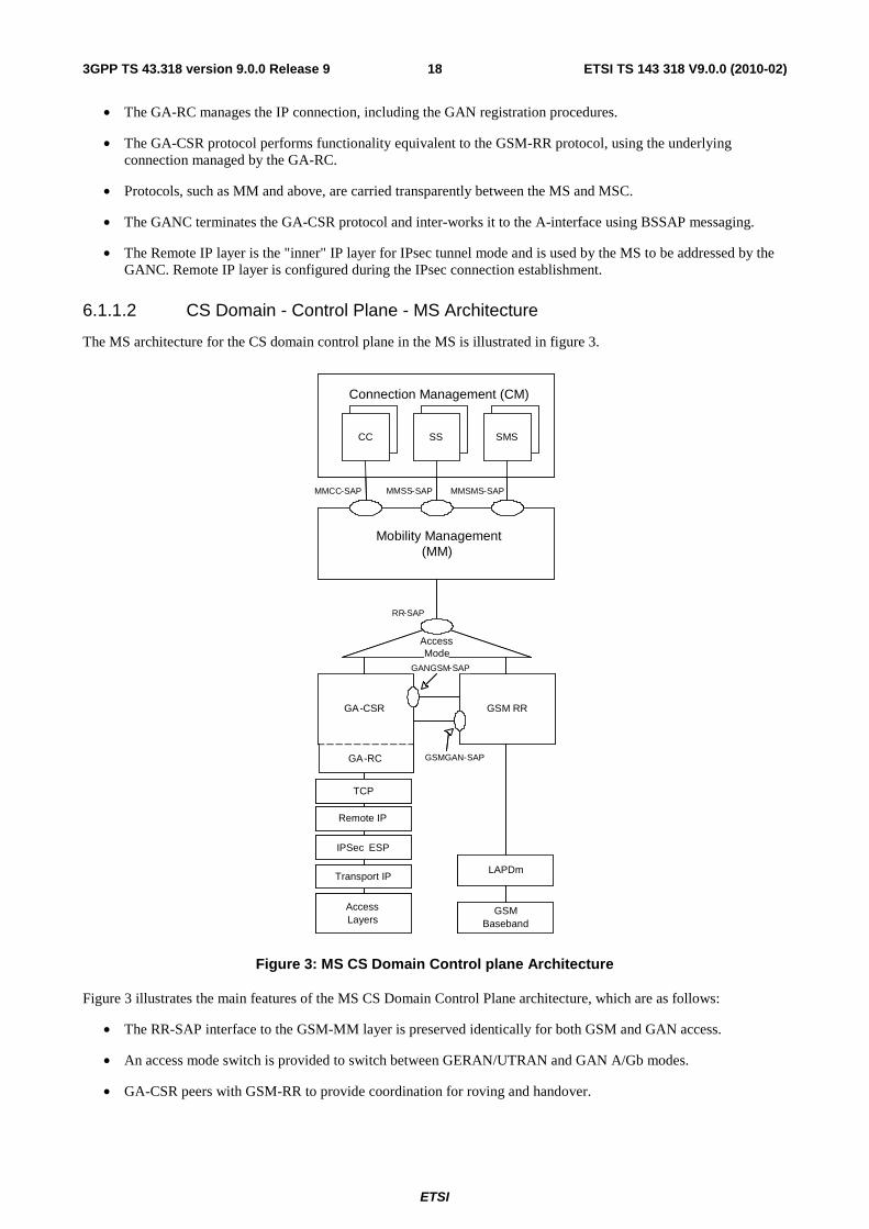
6.1.1.2 CS Domain - Control Plane - MS Architecture
The MS architecture for the CS domain control plane in the MS is illustrated in figure 3.
Connection Management (CM)
Mobility Management(MM)
CC SS SMS
MMCC -SAP MMSS -SAP MMSMS -SAP
Access Mode
RR - SAP
GA - CSR GSM RR
LAPDm
GANGSM - SAP
GSMGAN -SAP
GSM Baseband
TCP
Remote IP
IPSec ESP
Transport IP
Access Layers
GA - RC
Connection Management (CM)
Mobility Management(MM)
CC SS SMS
MMCC -SAP MMSS -SAP MMSMS -SAP
Access Mode
RR - SAP
GA - CSR GSM RR
LAPDm
GANGSM - SAP
GSMGAN -SAP
GSM Baseband
TCP
Remote IP
IPSec ESP
Transport IP
Access Layers
GA - RC
Figure 3: MS CS Domain Control plane Architecture
Figure 3 illustrates the main features of the MS CS Domain Control Plane architecture, which are as follows:
• The RR-SAP interface to the GSM-MM layer is preserved identically for both GSM and GAN access.
• An access mode switch is provided to switch between GERAN/UTRAN and GAN A/Gb modes.
• GA-CSR peers with GSM-RR to provide coordination for roving and handover.

ETSI
ETSI TS 143 318 V9.0.0 (2010-02)193GPP TS 43.318 version 9.0.0 Release 9
6.1.2 CS Domain - User Plane
6.1.2.1 CS Domain - User Plane - GAN Architecture
The GAN protocol architecture in support of CS domain user plane is illustrated figure 4.
GANC MS
Speech Bearer
Physical Layers
MSC
A
Speech Bearer
Physical Layers
Codec/Rate Adaptation
Access Layers
Transcoding (if necessary)
Codec/Rate Adaptation
Access Layers
Transport IP Transport IP Transport IP
RTP/UDP RTP/UDP
Up Interface
Generic IP Network
Access Layers
Remote IP IPSec ESP
Remote IP IPSec ESP
IWF(if necessary)
Figure 4: Up CS Domain User Plane Protocol Architecture
The main features of the CS domain user plane of the Up interface are as follows:
• The underlying Access Layers and Transport IP layer provides the generic connectivity between the MS and the GANC.
• The IPsec layer provides encryption and data integrity.
• CS domain user plane is transported over RTP/UDP between MS and GANC.
• Support for AMR FR codec, as specified in 3GPP TS 26.071 [7], is mandatory when operating in GAN A/Gb mode, with support for other codecs being optional.
• CS-data is transported over RTP/UDP, by defining a new RTP frame format to carry the TAF-TRAU (V.110-like) frames over RTP.
• TTY is transported using CTM over GSM codec over RTP/UDP.
• The GANC re-frames the CS domain user plane between RTP/UDP and the speech bearers over the A-interface.

ETSI
ETSI TS 143 318 V9.0.0 (2010-02)203GPP TS 43.318 version 9.0.0 Release 9
6.2 PS Domain (GAN A/Gb mode)
6.2.1 PS Domain - GAN Architecture
6.2.1.1 PS Domain - Control Plane - GAN Architecture
The GAN architecture in support of PS Domain Control Plane is illustrated in figure 5.
GANC MS
LLC
Upper Layers
SGSN
Upper Layers
BSSGP
Physical Physical
BSSGP
Transport IP
Gb Up Interface
Transport IP Transport IP
LLC
Remote IP Remote IP
Relay
TCP
LLC
Upper Layers
Network Service
Transport IP
Access Layers
Generic IP Network
Remote IP IPSec ESP IPSec ESP
TCP TCP
GA-PSR
TCP GA-RC
Access Layers
GA-PSR GA-RC
Access Layers
Transport IP
Network Service
Figure 5: Up PS Domain Control Plane Architecture
The main features of the Up interface for the PS domain control plane are as follows:
• The underlying Access Layers and Transport IP layer provides the generic connectivity between the MS and the GANC.
• The IPsec layer provides encryption and data integrity.
• TCP provides reliable transport for the GA-PSR between MS and GANC.
• The GA-RC manages the IP connection, including the GAN registration procedures.
• The GA-PSR protocol performs functionality equivalent to the GPRS-RLC protocol. The concept of a TBF is replaced by mechanisms to manage an IP connection between MS and GANC.
NOTE: No QoS can be assured when utilizing the GA-PSR transport channel.
• Protocols, such as LLC and above, are carried transparently between the MS and CN.
• The GANC terminates the GA-PSR protocol and inter-works it to the Gb-interface using BSSGP.

ETSI
ETSI TS 143 318 V9.0.0 (2010-02)213GPP TS 43.318 version 9.0.0 Release 9
6.2.1.2 PS Domain - User Plane - GAN Architecture
The GAN architecture for PS Domain User Plane is illustrated in figure 6.
GANC MS
SNDCP
IP
SGSN
LLC
To GGSN
BSSGP
Physical Physical
BSSGP
Transport IP
Gb Up Interface
Transport IP
SNDCP
Generic IP Network
UDP UDP
Relay
Remote IP Remote IP
LLC
Network Service
Access Layers
GA-PSR
Transport IP
GA-PSR
IPSec ESP IPSec ESP
Access Layers
Access Layers
Network Service
Figure 6: Up PS Domain User Plane Protocol Architecture
The main features of the Up interface for PS domain user plane are as follows:
• The underlying Access Layers and Transport IP layer provides the generic connectivity between the MS and the GANC.
• The IPsec layer provides encryption and data integrity.
• The GA-PSR operates between the MS to the GANC transporting the upper layer payload (i.e. user plane data)across the Up interface.
• Protocols and data, such as LLC and above, are carried transparently between the MS and CN.
• The GANC terminates the GA-PSR protocol and inter-works it to the Gb-interface using BSSGP.

ETSI
ETSI TS 143 318 V9.0.0 (2010-02)223GPP TS 43.318 version 9.0.0 Release 9
6.2.2 PS Domain - MS Architecture
The MS architecture for the PS domain is illustrated in more detail in figure 7.
Logical Link Control
(LLC)
GMM SNDCP
SMS
GA - PSR GPRS RLC
AccessMode
GRR - SAP GMMRR - SAP
GANGPRS - SAP
GPRSGAN - SAP
IP
App
MAC
GSM Baseband
TCP UDP
AccessLayers
GA- RC
Logical Link Control
(LLC)
GMM SNDCP
SMS
GA - PSR GPRS RLC
AccessMode
GRR - SAP GMMRR-SAP
GANGPRS - SAP
GPRSGAN - SAP
IP
App
MAC
GSM Baseband
TCP UDP
Remote IPRemote IP
IPSec ESP IPSec ESP
Transport IPTransport IP
AccessLayers
GA- RC
Figure 7: MS PS Domain Architecture
Figure 7 illustrates the main features of the MS PS Domain architecture, which are as follows:
• The GRR-SAP to the GPRS-LLC layer is preserved.
• The GMMRR-SAP interface to the GPRS-GMM layer is preserved.
• An access mode switch is provided to switch between GPRS and GAN A/Gb modes.
• GA-PSR peers with GPRS-RLC to provide coordination for roving and PS handover.

ETSI
ETSI TS 143 318 V9.0.0 (2010-02)233GPP TS 43.318 version 9.0.0 Release 9
6.3 CS Domain (GAN Iu mode)
6.3.1 CS Domain - Control Plane
6.3.1.1 CS Domain - Control Plane - GAN Architecture
The GAN Iu mode architecture in support of the CS Domain control plane is illustrated in figure 7a.
Figure 7a: CS Domain Control Plane Architecture
The main features of the GAN Iu mode CS domain control plane architecture are as follows:
• The underlying Access Layers and Transport IP layer provides the generic connectivity between the MS and the GANC.
• The IPsec layer provides encryption and data integrity between the MS and GANC.
• The Remote IP layer is the "inner" IP layer for IPsec tunnel mode and is used by the MS to be addressed by the GANC. The Remote IP layer is configured during the IPsec connection establishment.
• A single TCP connection is used to provide reliable transport for both the GA-RC and GA-RRC signaling between the MS and GANC. The TCP connection is managed by GA-RC and is transported using the Remote IP layer.
• NAS protocols, such as MM and above, are carried transparently between the MS and MSC.
• The Generic Access Resource Control (GA-RC) protocol manages the Up session, including the GAN discovery and registration procedures.
• The Generic Access Radio Resource Control (GA-RRC) protocol performs functionality equivalent to the UTRAN RRC protocol, using the underlying Up session managed by the GA-RC. Note that GA-RRC includes both CS service and PS service-related signaling messages.
• The GANC terminates the CS-related GA-RRC protocol and inter-works it to the RANAP protocol over the Iu-cs interface.
• The Iu-cs signalling transport layer options (both ATM and IP-based) are defined in TS 25.412 [47].

ETSI
ETSI TS 143 318 V9.0.0 (2010-02)243GPP TS 43.318 version 9.0.0 Release 9
6.3.1.2 CS Domain - Control Plane - MS Architecture
The MS architecture for the CS domain control plane is illustrated in figure 7b. The MS architecture illustrates support for both GAN A/Gb mode and GAN Iu mode.
UTRAN
RRC
Access Mode Switch
MM
CC
GERAN
RRC
RR (GERAN)
GA-RRC/
GA-CSR/GA-RC
SMSSS
Connection Management (CM)
to/from
UTRAN RRC
to/from
GERAN RRC
MMCC MMSS MMSMS
RR (UTRAN)
RR (UTRAN) RR (UTRAN) RR (GERAN)
UTRAN
RLC/MAC
UTRAN
Baseband
LAPDm
GERAN
Baseband
Access
Layers
IPSec Tunnel
TCP/IP
RR (GERAN)
Figure 7b: MS CS Domain Control Plane Architecture
Figure 7b illustrates the main features of the MS CS domain control plane architecture, which are as follows:
• The UTRAN RR-SAP interface to the MM layer is preserved identically for both UTRAN and GAN Iu mode access.
• The GERAN RR-SAP interface to the MM layer is preserved identically for both GERAN and GAN A/Gb mode access.
• An access mode switch is provided to switch between GERAN/UTRAN and GAN modes.
• GA-RRC (GAN Iu mode) peers with UTRAN-RRC and GERAN-RRC to provide coordination for roving and handover.
• GA-CSR (GAN A/Gb mode) peers with UTRAN-RRC and GERAN-RRC to provide coordination for roving and handover.

ETSI
ETSI TS 143 318 V9.0.0 (2010-02)253GPP TS 43.318 version 9.0.0 Release 9
6.3.2 CS Domain - User Plane
6.3.2.1 CS Domain - User Plane - GAN Architecture
The GAN Iu mode protocol architecture in support of the CS domain user plane is illustrated figure 7c.
Access Layers
Transport IP
IPSec ESP
Remote IP
CS User Data
Access Layers
Transport IP
Access Layers
Transport IP
IPSec ESP
Iu UP
CS User Data
Up Iu-cs
UDP
MS Generic IP Network GANC MSC
RTP
Remote IP
UDP
RTP
Interworking
Iu UP
Transport Network Control
and Data
Transport
Layers
(TS 25.414)
Transport Network Control
and Data
Transport
Layers
(TS 25.414)
Figure 7c: CS Domain User Plane Protocol Architecture
The main features of the GAN CS domain user plane architecture are as follows:
• The underlying Access Layers and Transport IP layer provides the generic connectivity between the MS and the GANC.
• The IPsec layer provides encryption and data integrity.
• CS domain user plane is transported over RTP/UDP between MS and GANC.
• Support for AMR FR codec, as specified in 3GPP TS 26.071 [7], is mandatory when operating in GAN Iu mode, with support for other codecs being optional.
• CS-data is transported over RTP/UDP, by defining a new RTP frame format to carry the TAF-TRAU (V.110-like) frames over RTP.
• TTY is transported using CTM over GSM codec over RTP/UDP.
• The GANC provides interworking between RTP/UDP and the circuit switched bearers over the Iu-cs interface.
• The GANC supports the Iu User Plane (Iu UP) protocol. Each Iu UP protocol instance may operate in either transparent or support modes, as described in 25.415 [50]; the mode choice is indicated to the GANC by the MSC using RANAP.
• The Iu-cs data transport layers (both ATM and IP-based) and associated transport network control options are defined in 25.414 [49].

ETSI
ETSI TS 143 318 V9.0.0 (2010-02)263GPP TS 43.318 version 9.0.0 Release 9
6.3.2.2 CS Domain - User Plane - MS Architecture
The MS architecture for the CS domain user plane is illustrated in figure 7d. The MS architecture illustrates support for both GAN A/Gb mode and GAN Iu mode.
Figure 7d: MS CS Domain User Plane Architecture
Figure 7d illustrates the main features of the MS CS domain user plane architecture, which are as follows:
• An access mode switch is provided to switch between GERAN/UTRAN and GAN modes; i.e., to route CS user plane data—either speech or circuit switched data—to the active access subsystem.
ETSI
ETSI TS 143 318 V9.0.0 (2010-02)273GPP TS 43.318 version 9.0.0 Release 9
6.4 PS Domain (GAN Iu mode)
6.4.1 PS Domain - Control Plane
6.4.1.1 PS Domain - Control Plane - GAN Architecture
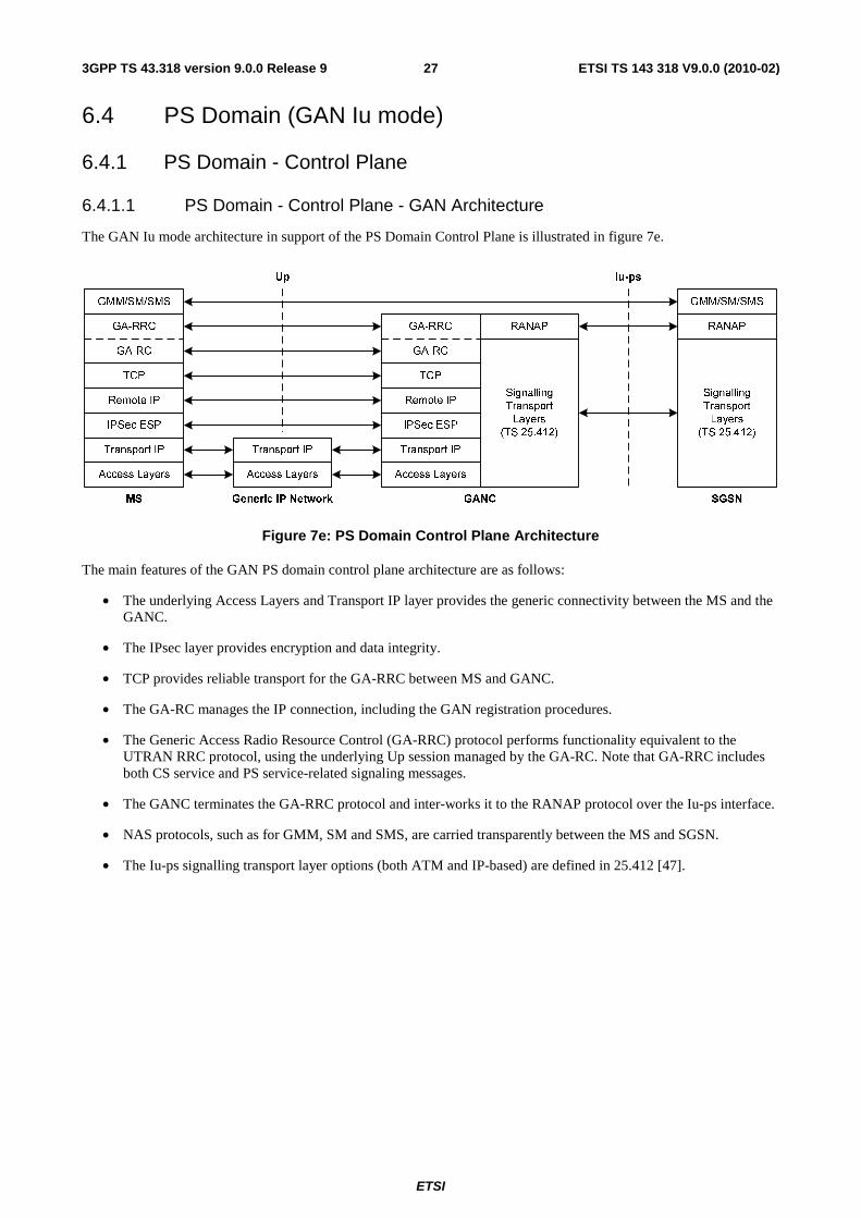
The GAN Iu mode architecture in support of the PS Domain Control Plane is illustrated in figure 7e.
Figure 7e: PS Domain Control Plane Architecture
The main features of the GAN PS domain control plane architecture are as follows:
• The underlying Access Layers and Transport IP layer provides the generic connectivity between the MS and the GANC.
• The IPsec layer provides encryption and data integrity.
• TCP provides reliable transport for the GA-RRC between MS and GANC.
• The GA-RC manages the IP connection, including the GAN registration procedures.
• The Generic Access Radio Resource Control (GA-RRC) protocol performs functionality equivalent to the UTRAN RRC protocol, using the underlying Up session managed by the GA-RC. Note that GA-RRC includes both CS service and PS service-related signaling messages.
• The GANC terminates the GA-RRC protocol and inter-works it to the RANAP protocol over the Iu-ps interface.
• NAS protocols, such as for GMM, SM and SMS, are carried transparently between the MS and SGSN.
• The Iu-ps signalling transport layer options (both ATM and IP-based) are defined in 25.412 [47].

ETSI
ETSI TS 143 318 V9.0.0 (2010-02)283GPP TS 43.318 version 9.0.0 Release 9
6.4.1.2 PS Domain - Control Plane - MS Architecture
The MS architecture for the PS domain control plane is illustrated in figure 7f. The MS architecture illustrates support for both GAN A/Gb mode and GAN Iu mode.
Figure 7f: MS PS Domain Control Plane Architecture
Figure 7f illustrates the main features of the MS PS domain control plane architecture, which are as follows:
• The UTRAN RABMAS-SAP and GMMAS-SAP interfaces to the MM layer are preserved identically for both UTRAN and GAN Iu mode access.
• The GERAN GRR-SAP and GMMRR-SAP interfaces to the MM layer are preserved identically for both GERAN and GAN A/Gb mode access.
• An access mode switch is provided to switch between GERAN/UTRAN and GAN modes.
• GA-RRC (GAN Iu mode) peers with UTRAN-RRC and GERAN-RRC to provide coordination for roving and handover.
• GA-PSR (GAN A/Gb mode) peers with UTRAN-RRC and GERAN-RRC to provide coordination for roving and handover.

ETSI
ETSI TS 143 318 V9.0.0 (2010-02)293GPP TS 43.318 version 9.0.0 Release 9
6.4.2 PS Domain - User Plane
6.4.2.1 PS Domain - User Plane - GAN Architecture
The GAN Iu mode architecture for the PS Domain User Plane is illustrated in figure 7g.
Figure 7g: PS Domain User Plane Protocol Architecture
The main features of the GAN PS domain user plane architecture are as follows:
• The underlying Access Layers and Transport IP layer provides the generic connectivity between the MS and the GANC.
• The IPsec layer provides encryption and data integrity.
• The GA-RRC protocol operates between the MS to the GANC transporting the upper layer payload (i.e. user plane data) across the Up interface.
• PS user data is carried transparently between the MS and CN.
• The GANC terminates the GA-RRC protocol and inter-works it to the Iu-ps interface using GTP-U.

ETSI
ETSI TS 143 318 V9.0.0 (2010-02)303GPP TS 43.318 version 9.0.0 Release 9
6.4.2.2 PS Domain - User Plane - MS Architecture
The MS architecture for the PS domain user plane is illustrated in figure 7h.
UTRAN
RLC/MAC
UTRAN
Baseband
GERAN
RLC/MAC
GERAN
Baseband
Access
Layers
IPSec Tunnel
GA-RRC,
GA-PSR
UDP/IP
PDCP
Access Mode Switch
LLC
GRR
QoS1QoS4 QoS3 QoS2
SNDCP
IP
PS User Plane Routing Service
PDCP
PDCP PDCP GRRGRR
Figure 7h: MS PS Domain User Plane Architecture
Figure 7h illustrates the main features of the MS PS domain user plane architecture, which are as follows:
• The UTRAN PDCP-SAP interface to the PS user plane upper layers is preserved identically for both UTRAN and GAN Iu mode access.
• The GERAN GRR-SAP interface to the PS user plane upper layers is preserved identically for both GERAN and GAN A/Gb mode access.
• An access mode switch is provided to switch between GERAN/UTRAN and GAN modes; i.e., to route PS user plane data to the active access subsystem.
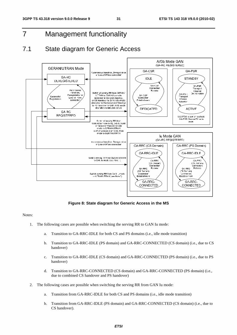
ETSI
ETSI TS 143 318 V9.0.0 (2010-02)313GPP TS 43.318 version 9.0.0 Release 9
7 Management functionality
7.1 State diagram for Generic Access
GA-RC
DEREGISTERED
GA-RC
REGISTERED
Successful
Registration
Autonomous
transition,
Deregistration or
Loss of IPSec
connection
GA-RRC-IDLE
GA-RRC
(CS Domain)
Connection
Establishment
GA-RRC
(CS Domain)
Connection
Release
Autonomous transition, Deregistration
or Loss of IPSec connection
Switch serving RR from GERAN/UTRAN
to GAN Iu mode (see Note 1)
Switch serving RR from GAN Iu mode
to GERAN/UTRAN (see Note 2)
GERAN/UTRAN Mode
GA-RRC (CS Domain)
Iu Mode GAN
(GA-RC REGISTERED)
GA-RRC-
CONNECTED
IDLE
GA-CSR
Connection
Establishment
GA-CSR
Connection
Release
GA-CSR
A/Gb Mode GAN
(GA-RC REGISTERED)
DEDICATED
STANDBY
GA-PSR
Transport
Channel
Activation
GA-PSR
Transport
Channel
De-Activation
GA-PSR
ACTIVE
Autonomous transition, Deregistration
or Loss of IPSec connection
Switch of serving RR from GERAN/
UTRAN to GAN A/Gb mode
(transition to Idle and Standby),
or CS Handover to GAN A/Gb mode
(transition to Dedicated and Standby)
or PS Handover to GAN A/Gb mode
(transition to Idle and Active)
Switch of serving RR from
GAN A/Gb mode to GERAN/UTRAN
or Handover from GAN A/Gb
mode to GERAN/UTRAN
or PS Handover from GAN A/Gb
mode to GERAN/UTRAN
LLC-PDU is sent or received.
GA-PSR Channel Timer is
reset.
GA-RRC-IDLE
GA-RRC
(PS Domain)
Connection
Establishment
GA-RRC
(PS Domain)
Connection
Release
GA-RRC (PS Domain)
GA-RRC-
CONNECTED
Figure 8: State diagram for Generic Access in the MS
Notes:
1. The following cases are possible when switching the serving RR to GAN Iu mode:
a. Transition to GA-RRC-IDLE for both CS and PS domains (i.e., idle mode transition)
b. Transition to GA-RRC-IDLE (PS domain) and GA-RRC-CONNECTED (CS domain) (i.e., due to CS handover)
c. Transition to GA-RRC-IDLE (CS domain) and GA-RRC-CONNECTED (PS domain) (i.e., due to PS handover)
d. Transition to GA-RRC-CONNECTED (CS domain) and GA-RRC-CONNECTED (PS domain) (i.e., due to combined CS handover and PS handover)
2. The following cases are possible when switching the serving RR from GAN Iu mode:
a. Transition from GA-RRC-IDLE for both CS and PS domains (i.e., idle mode transition)
b. Transition from GA-RRC-IDLE (PS domain) and GA-RRC-CONNECTED (CS domain) (i.e., due to CS handover).

ETSI
ETSI TS 143 318 V9.0.0 (2010-02)323GPP TS 43.318 version 9.0.0 Release 9
c. Transition from GA-RRC-IDLE (CS domain) and GA-RRC-CONNECTED (PS domain) (i.e., due to PS handover)
d. Transition from GA-RRC-CONNECTED (CS domain) and GA-RRC-CONNECTED (PS domain) (i.e., due to combined CS handover and PS handover)
3. There is no requirement for the MS to support both GAN Iu mode and GAN A/Gb mode.
7.2 GA-RC (Generic Access Resource Control)
7.2.1 General
The GA-RC protocol provides a resource management layer, with the following functions:
• discovery and Registration with GANC, including GAN mode selection (GAN A/Gb mode or GAN Iu mode);
• registration Update with GANC;
• application level keep-alive with GANC; and
• support for identification of the AP being used for GAN access.
7.2.2 States of the GA-RC sub-layer
The GA-RC sub-layer in the MS can be in one of two states - GA-RC-DEREGISTERED or GA-RC-REGISTERED - as illustrated in figure 8.
In the GA-RC-DEREGISTERED state, the MS may be in a GAN coverage area; however, the MS has not registered successfully with the GANC and cannot exchange GA-CSR and GA-PSR signalling messages (GAN A/Gb mode) or GA-RRC messages (GAN Iu mode) with the GANC. The MS may initiate the GAN Registration procedure when in the GA-RC-DEREGISTERED state. The MS returns to GA-RC-DEREGISTERED state on loss of TCP or IPsec connection.
In the GAN A/Gb mode GA-RC-REGISTERED state, the MS is registered with a GANC, has an IPsec and an TCP connection established to the Serving GANC, through which the MS may exchange GA-CSR or GA-PSR signaling messages with the GANC, and the SAP between the GA-CSR and MM entity and the GA-PSR and the GMM entity are not active. In the GA-RC-REGISTERED state, the MS may be camped on GERAN or UTRAN, active in GERAN or UTRAN (e.g. a GSM RR or a UTRAN RRC connection may be established) or may have no GERAN or UTRAN service while still maintaining the registration in the GAN.
In the GAN Iu mode GA-RC-REGISTERED state, the MS is registered with the Serving GANC. The MS has an IPsec tunnel and a TCP connection established to the Serving GANC through which the MS may exchange GA-RC or GA-RRC signaling messages with the GANC. The SAP between the GA-RRC and MM entity and the GA-RRC and the GMM entity are not active. In the GA-RC-REGISTERED state, the MS may be camped on GERAN or UTRAN, active in GERAN or UTRAN (e.g. a GSM RR or a UTRAN RRC connection may be established) or may have no GERAN or UTRAN service while still maintaining the registration in the GAN.
7.3 GA-CSR (Generic Access Circuit Switched Resources)
7.3.1 General
The GA-CSR protocol provides a resource management layer, which is equivalent to the GSM-RR and provides the following functions:
• setup of bearer for CS traffic between the MS and GANC;
• handover support between GERAN and GAN; and

ETSI
ETSI TS 143 318 V9.0.0 (2010-02)333GPP TS 43.318 version 9.0.0 Release 9
• functions such as GPRS suspension, paging, ciphering configuration, classmark change.
7.3.2 States of the GA-CSR sub-layer
The GA-CSR sub-layer in the MS can be in two states -GA-CSR-IDLE or GA-CSR-DEDICATED as illustrated in figure 8.
The MS enters GA-CSR-IDLE state from GA-RC-REGISTERED state, when the MS switches the serving RR entity to GA-CSR and the SAP between the MM and the GA-CSR is activated. Simultaneously, the GA-PSR acquires the control of the RLC GRR and GMMRR SAPs and transitions to GA-PSR- STANDBY state. While the MS remains in GAN A/Gb mode it performs registration Update and application level keep-alive with the GANC as per the GA-RC-REGISTERED state.
The MS moves from the GA-CSR-IDLE state to the GA-CSR-DEDICATED state when the GA-CSR connection is established and returns to GA-CSR-IDLE state when the GA-CSR connection is released. Upon GA-CSR connection release an indication that no dedicated resources exist is passed to the upper layers.
The MS may also enter GA-CSR-DEDICATED state from GA-RC-REGISTERED state of GERAN/UTRAN mode when Handover to GAN is being performed. In the same way, the MS enters GA-RC-REGISTERED state of GERAN/UTRAN mode from GA-CSR-DEDICATED when Handover from GAN is being performed.
7.4 GA-PSR (Generic Access Packet Switched Resources) The GA-PSR protocol provides the following services:
• delivery of GPRS signalling, SMS messages over the secure tunnel;
• paging, flow control, GPRS transport channel management;
• PS handover support between GERAN/UTRAN mode and GAN A/Gb mode; and
• transfer of GPRS user plane data.
The GA-PSR Transport Channel (GA-PSR TC) provides the association between the MS and GANC for the transport of GPRS user data over the Up interface. Given that the GAN user data transport is UDP based, the GA-PSR Transport Channel is associated with corresponding MS and GANC IP addresses and UDP ports used for GPRS user data transfer. The MS and GANC manage the GA-PSR Transport Channel based on the requests for data transfer and the configurable GA-PSR Channel Timer.
7.4.1 States of the GA-PSR sub-layer
The GA-PSR sub-layer in the MS can be in two states - GA-PSR-STANDBY or GA-PSR-ACTIVE - as illustrated in figure 8.
• GA-PSR-STANDBY: This is the initial/default state of the mobile station in GAN A/Gb mode. The MS is not able to send or receive GPRS user data to and from the GANC. The GA-PSR Transport Channel does not exist when the MS is in GA-PSR-STANDBY state. The GANC or the MS needs to activate the GA-PSR Transport Channel before sending any GPRS user data. When the MS GA-PSR successfully establishes a GA-PSR Transport Channel, it transitions to the GA-PSR-ACTIVE state.
• GA-PSR-ACTIVE: The MS is able to send and receive GPRS user data to and from the GANC. The corresponding GA-PSR Transport Channel exists.
Upon a successful switch to GAN A/Gb mode as a result of rove-in, the MS GA-PSR acquires the control of the RLC GRR and GMMRR SAPs, and transitions to GA-PSR-STANDBY state and GA-PSR TC activation may then be triggered.
After successful GA-PSR TC activation when in GAN A/Gb mode, the MS GA-PSR transitions to GA-PSR-ACTIVE state. The following are the possible triggers for GA-PSR TC activation when the MS is in the GA-PSR-STANDBY state in GAN A/Gb mode:

ETSI
ETSI TS 143 318 V9.0.0 (2010-02)343GPP TS 43.318 version 9.0.0 Release 9
• The MS LLC entity initiates the uplink data transfer using LLC SAPI 3, 5, 9 or 11 and the GA-PSR sub-layer is in the GA-PSR-STANDBY state.
• The GANC initiates GA-PSR TC activation; i.e. the MS receives a GA-PSR-ACTIVATE UTC REQ message from the GANC (see sub-clause 8.16.4).
As described in 3GPP TS 43.129 [44], the MS and GANC establish a GA-PSR TC during the PS handover preparation phase which results in MS enabling the reception of downlink LLC PDUs. Upon a successful switch to GAN A/Gb mode as a result of receiving the PS Handover Command, the MS transitions to GA-PSR-ACTIVE state, the MS GA-PSR acquires the control of the RLC GRR and GMMRR SAPs and enables the transmission of uplink LLC PDUs on the allocated GA-PSR TC.
Upon the successful GA-PSR TC activation and in parallel with transition to GA-PSR-ACTIVE state, the MS GA-PSR starts the GA-PSR Channel Timer. When the GA-PSR Channel Timer expires, the MS sends a message to the GANC to initiate GA-PSR TC deactivation. Upon successful GA-PSR TC deactivation, the MS GA-PSR transitions to GA-PSR-STANDBY state.
At any time, while in GAN A/Gb mode, if the serving RR entity is switched to GSM-RR, the GA-PSR is disconnected from GPRS SAPs and the MS enters GERAN/UTRAN mode. Simultaneously, the MS will release the associated GA-PSR TC regardless of the GA-PSR Channel Timer status.
The MS GA-PSR maintains one GA-PSR TC for all active user data flows; i.e. if the GA-PSR is in GA-PSR-ACTIVE state, any uplink user data packet is transferred using the active GA-PSR TC regardless of the associated PFC and LLC SAP. The GA-PSR Channel Timer is restarted whenever any uplink user data packet is sent or downlink user data packet received regardless of the associated PFC and LLC SAP.
7.4a GA-RRC
7.4a.1 General
The GA-RRC protocol provides a resource management layer which is equivalent to UTRAN-RRC and supports the following functions:
• setup of transport channels for CS and PS traffic between the MS and GANC;
• CS and PS handover support between GERAN/UTRAN and GAN;
• direct transfer of NAS messages between the MS and the core network; and
• other functions such as CS and PS paging and security configuration.
7.4a.2 States of the GA-RRC sub-layer
The GA-RRC sub-layer in the MS contains two entities, the CS domain GA-RRC sublayer entity and the PS domain GA-RRC sublayer entity (as illustrated in Figure 8). These entities operate independently and in parallel; e.g., two GA-RRC connections are established in the case of simultaneous CS and PS services, one GA-RRC connection for each domain.
Each GA-RRC sub-layer entity in the MS can be in one of two states, GA-RRC-IDLE or GA-RRC-CONNECTED as illustrated in figure 8.
Both the CS GA-RRC sub-layer entity and the PS GA-RRC sublayer entity in the MS enters the GA-RRC-IDLE state when the MS switches the serving RR entity to GA-RRC and the SAP between the NAS and the GA-RRC is activated. This switch may occur only when the GA-RC is in the GA-RC-REGISTERED state.
The CS/PS GA-RRC sublayer entity in the MS moves from the GA-RRC-IDLE state to the GA-RRC-CONNECTED state when the CS/PS GA-RRC connection is established and returns to the GA-RRC-IDLE state when the CS/PS GA-RRC connection is released. Upon CS/PS GA-RRC connection release, an indication that no dedicated resources exist for the domain is passed to the upper layers.

ETSI
ETSI TS 143 318 V9.0.0 (2010-02)353GPP TS 43.318 version 9.0.0 Release 9
The CS/PS GA-RRC sublayer entity in the MS may also enter the GA-RRC-CONNECTED state while in the GA-RC-REGISTERED state in GERAN/UTRAN mode when CS/PS handover to GAN is being performed.
7.5 Security Mechanisms GAN supports security mechanisms at different levels and interfaces as depicted in figure 9.
Figure 9: GAN Security Mechanisms
1. The security mechanisms over the Up interface protect signalling, voice and data traffic flows between the MS and the GANC from unauthorized use, data manipulation and eavesdropping; i.e. authentication, encryption and data integrity mechanisms are supported.
2. Authentication of the subscriber by the core network occurs between the MSC/VLR or SGSN and the MS and is transparent to the GANC - however, there is a cryptographic binding between the MS-CN authentication and the MS-GANC authentication to prevent man in the middle attacks. GPRS ciphering is the standard LLC layer ciphering that operates between the MS and the SGSN (not applicable to GAN Iu mode). These mechanisms are out of scope of the present document.
3. Additional application level security mechanisms may be employed in the PS domain to secure the end-to-end communication between the MS and the application server. For example, the MS may run the HTTP protocol over an SSL session for secure web access. These mechanisms are out of scope of the present document.
All signalling traffic and user-plane traffic sent between MS and GANC over the Up interface is protected by an IPsec tunnel between the MS and GANC-SEGW, that provides mutual authentication (using SIM credentials), encryption and data integrity using the same mechanisms as specified in 3GPP TS 33.234 [9].
8 High-Level Procedures for GAN A/Gb Mode
8.1 Mechanism of Mode Selection in Multi-mode terminals A Generic Access capable terminal may support any IP access technology in addition to the GERAN and possibly UTRAN radio interfaces. The MS may be either in the GERAN/UTRAN mode or in GAN mode of operation.
The MS can be configured to operate in one of the above two modes at any given time. There may be preferred mode of operation that can be configured by the user, or by the operator through various mechanisms, e.g. device management.
On power up, the MS always starts in GERAN/UTRAN mode and executes the normal power-up sequence as specified in 3GPP TS 23.122 [4]. Following this, the MS may switch into GAN mode based on mode selection preference determined by user preferences or operator configuration.
The various preferences for the MS that are possible are as follows:
• GERAN/UTRAN -only:
- The MS RR entity remains in GERAN/UTRAN mode and does not switch to GAN mode.

ETSI
ETSI TS 143 318 V9.0.0 (2010-02)363GPP TS 43.318 version 9.0.0 Release 9
• GERAN/UTRAN -preferred:
- The MS RR entity is in GERAN/UTRAN mode as long as there is a suitable GERAN cell or a suitable UTRAN cell available. If the MS cannot find a suitable GERAN cell or a suitable UTRAN cell to camp on, and MS has successfully registered with a GANC over the generic IP access network, then the MS switches to GAN mode. When the MS in GAN mode is able to find a suitable GERAN cell or a suitable UTRAN cell to camp on, or the MS has de-registered or loses connectivity with the GANC over the generic IP access network, the MS returns to GERAN/UTRAN mode.
• GAN-preferred:
- When the MS has successfully registered with the GAN over the generic IP access network, the MS switches to GAN mode and stays in this mode as long as the GAN is available. When the MS deregisters, or otherwise loses connectivity with the GAN over the generic IP access network, the MS switches to GERAN/UTRAN mode.
• GAN-only:
- The MS switches to GAN mode (after initial power up sequence in GERAN/UTRAN mode to obtain cellular network information, but excluding (G)MM procedures with GERAN core network) and does not switch to GERAN/UTRAN mode. During the initial power up sequence in GERAN/UTRAN mode the MS shall ignore paging message received through GERAN/UTRAN network.
8.2 PLMN Selection There shall be no change from the PLMN selection procedures in the NAS layers (MM and above) in the MS, with the exception that in GAN mode the 'in VPLMN background scan' shall be disabled.
A GANC can be only connected to one PLMN.
The PLMN selection in the NAS layers shall not lead to change of mode between GERAN/UTRAN mode and GAN mode. For a specific instance of PLMN selection only PLMNs available via GAN or only PLMNs available via GERAN/UTRAN are provided to the NAS layer (i.e. no combination of the PLMNs available via GERAN/UTRAN and GAN).
In the case of a GAN capable MS, a GANC selection process also may be required as part of the process of establishing the connectivity between the MS and the GANC. This takes place when, during GAN registration, a GAN capable MS has a choice among two or more GANC-PLMN pairs indicated by the Default GANC (i.e. in the GA-RC REGISTER REDIRECT message). The GANC selection process takes place while the MS is still in GERAN/UTRAN mode (i.e. before the MS roves into GAN mode) as follows:
- While a mobile station is attempting to become GAN registered, the GANC selection process shall attempt GAN registration with the currently registered PLMN if the currently registered PLMN is contained in the list of GAN PLMN pairs indicated by the Default GANC.
- If GAN registration with the currently registered PLMN is not possible and there are one or more remaining GANC-PLMN pairs that were received in the GAN PLMN list within a GA-RC REGISTER REDIRECT message, they shall all be treated as having sufficient received signal quality and PLMN selection should be performed according to the PLMN selection rules of 3GPP TS 22.011 [53] where the PLMN selected is in the GAN PLMN list.
If the MS does not have any stored information related to the Serving GANC for the cell ID or AP to which the MS is currently connected, the MS attempts to register with the Default GANC (always located in the HPLMN) stored in MS. The MS includes an indication, identifying the GANC as the Default GANC in the GA-RC REGISTER REQUEST message.
When an MS attempts to register on the Default GANC including an indication that it is in automatic PLMN selection mode:
- If the Default GANC wishes to serve the MS, the Default GANC responds with a GA-RC REGISTER ACCEPT message.
- If the Default GANC wishes to redirect the MS to another GANC within the HPLMN, the Default GANC responds with a GA-RC REGISTER REDIRECT message, not including a list of PLMN identities.
ETSI
ETSI TS 143 318 V9.0.0 (2010-02)373GPP TS 43.318 version 9.0.0 Release 9
- If the Default GANC wishes to redirect the MS to a PLMN that is not the HPLMN, the Default GANC responds with a GA-RC REGISTER REDIRECT message and includes a list of PLMNs that may provide GAN service to the MS in its current location. The list contains one or more PLMN identities along with the identities of their associated GANC and SEGW nodes (either in IP address or FQDN format). Following the GANC selection process, the GA-RC shall attempt to register on the associated GANC.
If at any time the user wishes to perform manual PLMN selection or a "User reselection" irrespective of whether the MS is in manual or automatic PLMN selection mode, the MS sends a GA-RC REGISTER REQUEST message to the Default GANC, including an indication that it is in manual PLMN selection mode. The Default GANC is not allowed to accept the registration and responds with a GA-RC REGISTER REDIRECT message and includes a list of PLMNs that may provide GAN service to the MS in its current location.
If the MS includes the identity of the current serving network in the GA-RC REGISTER REQUEST message, the Default GANC uses this to identify the list of PLMNs to send to the MS in the response message.
The GA-RC REGISTER REDIRECT message may inform a mobile station that GAN A/Gb mode, GAN Iu mode or both GAN A/Gb mode and GAN Iu mode are supported for each PLMN indicated by this message.
After successful registration with a serving GANC, the MS shall not store the PLMN list. The MS shall not use the PLMN list, provided to the MS during the registration procedure, for background scanning.
NOTE: An MS cannot use Generic Access in a VPLMN unless the HPLMN supports and authorises Generic Access.
After entering GAN A/Gb mode, a mobile station may trigger handover back to GERAN/UTRAN mode by sending a GA-CSR HANDOVER INFORMATION message or GA-PSR HANDOVER INFORMATION message to the GANC and including an ordered list of preferred GERAN/UTRAN cells. After entering GAN Iu mode, a mobile station may trigger handover back to GERAN/UTRAN mode by sending a GA-RRC RELOCATION INFORMATION message to the GANC and including an ordered list of preferred GERAN/UTRAN cells. In each case, the list of preferred GERAN/UTRAN cells shall include cells having the same PLMN as the currently registered PLMN (if at least one such cell is known to the MS).
8.3 Re-selection between GERAN/UTRAN and GAN modes
8.3.1 Rove-in (from GERAN/UTRAN mode to GAN mode)
This procedure is applicable only if GAN service is available, a MS is not in NC2 mode (as defined in 3GPP TS 45.008 [18]) and has an MS preference for:
• GAN-only;
• GAN-preferred or;
• GERAN/UTRAN-preferred and the MS cannot find a suitable GERAN cell or a suitable UTRAN cell to camp on.
Following successful GAN registration, the Access mode in the MS is switched to GAN mode. GA-CSR or GA-RRC entity in the MS reports to the NAS, the NAS-related system information received in the GAN Registration Procedure. The NAS considers the GANC allocated cell ID, as the current serving cell.
While in GAN mode, an MS in GERAN/UTRAN-preferred mode may perform GERAN/UTRAN cells monitoring according to 3GPP TS 45.008 and follow the behaviours according to 3GPP TS 23.122.
While in GAN mode, GERAN-RR and UTRAN RRC entities are detached from the RR-SAP in the MS, as a result the entities do not:
• inform NAS about any GERAN/UTRAN cell re-selection and/or the change of system information of the current camping cell;
• inform NAS about any newly found PLMN over GERAN or UTRAN; and
• act on any paging request message received over GERAN or UTRAN.
ETSI
ETSI TS 143 318 V9.0.0 (2010-02)383GPP TS 43.318 version 9.0.0 Release 9
Rove-in may be applied to support CS call re-establishment following the loss of an RR connection in GSM or to support packet service re-establishment following abnormal TBF release with cell reselection in GPRS. The support for call re-establishment is indicated to the MS in the GAN system information.
8.3.2 Rove-out (from GAN mode to GERAN/UTRAN mode)
This procedure is applicable when MS detaches from the generic IP access network, and its mode selection is GAN-preferred or when MS finds a suitable GERAN/UTRAN cell for camping on, and its mode selection is GERAN/UTRAN-preferred.
When the MS detaches from the generic IP access network, depending on prevailing circumstances the MS may be able to deregister first with the GANC.
For the GAN-preferred and GERAN/UTRAN-preferred mode selections, the MS detaches GA-CSR or GA-RRC from the RR-SAP and re-attaches GERAN-RR or UTRAN RRC to RR-SAP and restores normal GERAN-RR or UTRAN RRC functionality.
For the GAN-only mode selection, GA-CSR or GA-RRC remains attached to NAS and the MS stays in GAN mode (in "No Service" condition).
8.4 GAN Discovery and Registration related procedures
8.4.1 Discovery and Registration for Generic Access
8.4.1.1 General
The Discovery and Registration procedures are applicable only if the MS preference is operating in GAN-only, GAN-preferred or, if no allowable PLMN is available through GERAN/UTRAN, in GERAN/UTRAN-preferred mode.
Once the MS has established a connection to the generic IP access network, the mobile determines the appropriate GANC-SEGW to connect to, by completing the Discovery Procedure to the Provisioning GANC in the HPLMN of the MS. The Provisioning GANC provides the address of the Default GANC in the HPLMN of the MS, to which the mobile can register.
The MS attempts to register on the Default GANC provided by the Provisioning GANC during the Discovery procedure, by completing the Registration Procedure. The Default GANC may accept the Registration; redirect the MS to another GANC; or Reject the Registration.
8.4.1.2 Security Gateway Identification
The (U)SIM of the MS contains the FQDN (or IP address) of the Provisioning GANC and the associated SEGW or the MS derives this information based on information in the (U)SIM. If the MS does not have any information about other GANCs and associated SEGW stored, then the MS completes the Discovery procedure towards the Provisioning GANC.
As part of the Registration Procedure, the Default GANC can indicate whether this GANC and SEGW address or the address of a GANC that the MS is being redirected to, may be stored by the MS.
The MS may also store Serving GANC information for Serving GANCs with which the MS was able to complete a successful registration procedure. The default GANC is in control of whether the MS is allowed to store Serving GANC information. If there is no GERAN/UTRAN coverage in the AP location, the stored Serving GANC information shall be associated with the AP-ID. If there is GERAN/UTRAN coverage in the AP location, the stored Serving GANC information shall be associated with the GSM CGI or LAI and UTRAN CI. The stored Serving GANC information is:
• serving SEGW FQDN or IP address following successful registration;
• serving GANC FQDN or IP address following successful registration; and
• optionally, Serving GANC TCP port following successful registration and if returned from the network.
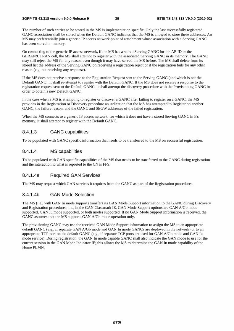
ETSI
ETSI TS 143 318 V9.0.0 (2010-02)393GPP TS 43.318 version 9.0.0 Release 9
The number of such entries to be stored in the MS is implementation specific. Only the last successfully registered GANC association shall be stored when the Default GANC indicates that the MS is allowed to store these addresses. An MS may preferentially join a generic IP access network point of attachment whose association with a Serving GANC has been stored in memory.
On connecting to the generic IP access network, if the MS has a stored Serving GANC for the AP-ID or the GERAN/UTRAN cell, the MS shall attempt to register with the associated Serving GANC in its memory. The GANC may still reject the MS for any reason even though it may have served the MS before. The MS shall delete from its stored list the address of the Serving GANC on receiving a registration reject or if the registration fails for any other reason (e.g. not receiving any response).
If the MS does not receive a response to the Registration Request sent to the Serving GANC (and which is not the Default GANC), it shall re-attempt to register with the Default GANC. If the MS does not receive a response to the registration request sent to the Default GANC, it shall attempt the discovery procedure with the Provisioning GANC in order to obtain a new Default GANC.
In the case when a MS is attempting to register or discover a GANC after failing to register on a GANC, the MS provides in the Registration or Discovery procedure an indication that the MS has attempted to Register on another GANC, the failure reason, and the GANC and SEGW addresses of the failed registration.
When the MS connects to a generic IP access network, for which it does not have a stored Serving GANC in it's memory, it shall attempt to register with the Default GANC.
8.4.1.3 GANC capabilities
To be populated with GANC specific information that needs to be transferred to the MS on successful registration.
8.4.1.4 MS capabilities
To be populated with GAN specific capabilities of the MS that needs to be transferred to the GANC during registration and the interaction to what is reported to the CN is FFS.
8.4.1.4a Required GAN Services
The MS may request which GAN services it requires from the GANC as part of the Registration procedures.
8.4.1.4b GAN Mode Selection
The MS (i.e., with GAN Iu mode support) transfers its GAN Mode Support information to the GANC during Discovery and Registration procedures; i.e., in the GAN Classmark IE. GAN Mode Support options are GAN A/Gb mode supported, GAN Iu mode supported, or both modes supported. If no GAN Mode Support information is received, the GANC assumes that the MS supports GAN A/Gb mode operation only.
The provisioning GANC may use the received GAN Mode Support information to assign the MS to an appropriate default GANC (e.g., if separate GAN A/Gb mode and GAN Iu mode GANCs are deployed in the network) or to an appropriate TCP port on the default GANC (e.g., if separate TCP ports are used for GAN A/Gb mode and GAN Iu mode service). During registration, the GAN Iu mode capable GANC shall also indicate the GAN mode to use for the current session in the GAN Mode Indicator IE; this allows the MS to determine the GAN Iu mode capability of the Home PLMN.

ETSI
ETSI TS 143 318 V9.0.0 (2010-02)403GPP TS 43.318 version 9.0.0 Release 9
The following table enumerates the discovery handling for the various combinations of MS and Home PLMN GAN mode capabilities.
Table 1: GAN Mode Selection procedures associated with GAN Discovery
Home PLMN GAN Mode Capabilities
MS GAN Mode Capabilities
A/Gb only Iu only Both
A/Gb only GANC: Handle as normal GAN A/Gb mode discovery
MS: Proceed with registration
GANC: No GAN Mode Support information provided or GAN A/Gb mode (only) indicated by MS, therefore Reject (Unspecified)
MS: Retry on next power-on
GANC: No GAN Mode Support information provided or GAN A/Gb mode (only) indicated by MS, therefore handle as normal GAN A/Gb mode discovery. Assign MS to GAN A/Gb-capable GANC.
MS: Proceed with registration
Iu only GANC: Handle as normal GAN A/Gb mode discovery
MS: Proceed with registration
GANC: GAN Iu Mode Support (only) indicated by MS, therefore accept and assign MS to GAN Iu mode capable GANC.
MS: Proceed with registration
GANC: GAN Iu Mode Support (only) indicated by MS, therefore accept and assign MS to GAN Iu mode capable GANC.
MS: Proceed with registration
Both GANC: Handle as normal GAN A/Gb discovery
MS: Proceed with registration
GANC: Support for both modes indicated by MS, therefore accept and assign MS to GAN Iu mode capable GANC.
MS: Proceed with registration
GANC: Support for both modes indicated by MS, therefore accept and assign MS to GAN A/Gb mode capable GANC or GAN Iu mode capable GANC (Note 1).
MS: Proceed with registration
Note 1: The GANC"s choice of GAN Iu mode versus GAN A/Gb mode may be based on other information received
in the GAN discovery message from the MS, information stored in the GANC, and on operator policy.
The default or serving GANC may use the received GAN Mode Support information to redirect the MS to a different GANC or a different TCP port on the current GANC. The GAN Iu mode capable GANC shall also indicate the GAN mode to use for the current session in the GAN Mode Indicator IE.
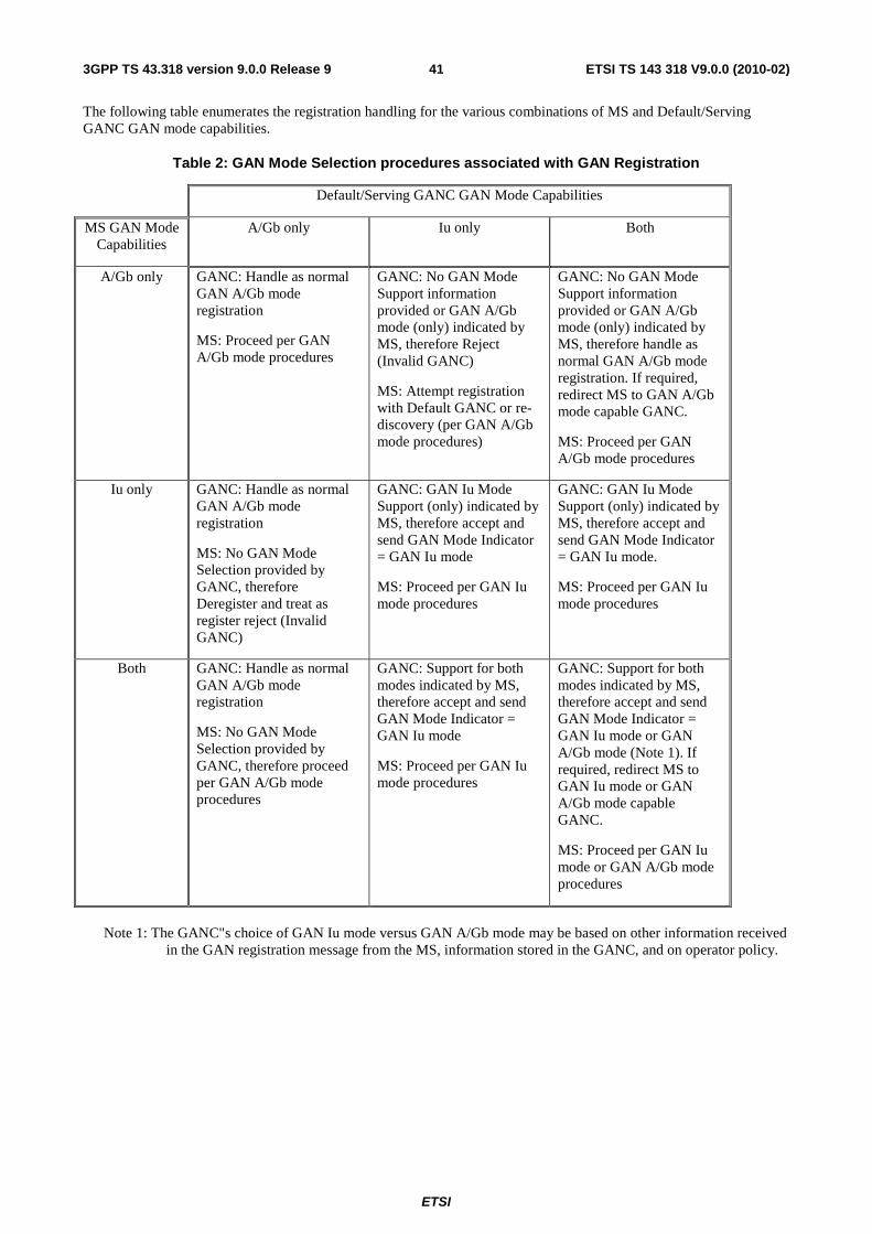
ETSI
ETSI TS 143 318 V9.0.0 (2010-02)413GPP TS 43.318 version 9.0.0 Release 9
The following table enumerates the registration handling for the various combinations of MS and Default/Serving GANC GAN mode capabilities.
Table 2: GAN Mode Selection procedures associated with GAN Registration
Default/Serving GANC GAN Mode Capabilities
MS GAN Mode Capabilities
A/Gb only Iu only Both
A/Gb only GANC: Handle as normal GAN A/Gb mode registration
MS: Proceed per GAN A/Gb mode procedures
GANC: No GAN Mode Support information provided or GAN A/Gb mode (only) indicated by MS, therefore Reject (Invalid GANC)
MS: Attempt registration with Default GANC or re-discovery (per GAN A/Gb mode procedures)
GANC: No GAN Mode Support information provided or GAN A/Gb mode (only) indicated by MS, therefore handle as normal GAN A/Gb mode registration. If required, redirect MS to GAN A/Gb mode capable GANC.
MS: Proceed per GAN A/Gb mode procedures
Iu only GANC: Handle as normal GAN A/Gb mode registration
MS: No GAN Mode Selection provided by GANC, therefore Deregister and treat as register reject (Invalid GANC)
GANC: GAN Iu Mode Support (only) indicated by MS, therefore accept and send GAN Mode Indicator = GAN Iu mode
MS: Proceed per GAN Iu mode procedures
GANC: GAN Iu Mode Support (only) indicated by MS, therefore accept and send GAN Mode Indicator = GAN Iu mode.
MS: Proceed per GAN Iu mode procedures
Both GANC: Handle as normal GAN A/Gb mode registration
MS: No GAN Mode Selection provided by GANC, therefore proceed per GAN A/Gb mode procedures
GANC: Support for both modes indicated by MS, therefore accept and send GAN Mode Indicator = GAN Iu mode
MS: Proceed per GAN Iu mode procedures
GANC: Support for both modes indicated by MS, therefore accept and send GAN Mode Indicator = GAN Iu mode or GAN A/Gb mode (Note 1). If required, redirect MS to GAN Iu mode or GAN A/Gb mode capable GANC.
MS: Proceed per GAN Iu mode or GAN A/Gb mode procedures
Note 1: The GANC"s choice of GAN Iu mode versus GAN A/Gb mode may be based on other information received
in the GAN registration message from the MS, information stored in the GANC, and on operator policy.

ETSI
ETSI TS 143 318 V9.0.0 (2010-02)423GPP TS 43.318 version 9.0.0 Release 9
8.4.1.5 Discovery Procedure
8.4.1.5.1 Normal Case
When an MS supporting GAN first attempts to connect to a GAN, the MS needs to identify the Default GANC. Each GAN capable MS can be configured with the FQDN (or IP address) of the Provisioning GANC and the associated SEGW or the MS can derive this FQDN based on information in the (U)SIM (see 3GPP TS 23.003 [43]). The MS first connects to a Provisioning GANC-SEGW and GANC in the HPLMN of the MS, by establishing a secure IPsec tunnel and a TCP connection using the provisioned or derived addresses. The MS obtains the FQDN or IP address of the Default GANC in the HPLMN and the associated SEGW, through the Discovery procedure.
If no GERAN/UTRAN coverage is available when an MS connects to the GANC for GAN service, then the GANC cannot necessarily determine the location of the MS for the purposes of assigning the MS to the correct serving GANC (e.g., to enable handover and location-based services). The GANC shall permit the operator to determine the service policy in this case; e.g. the operator could provide service to the user with certain limitations (possibly with a user interface indication on the MS).
NOTE: When the MS initiates the Discovery/Registration procedures and no GERAN/UTRAN coverage is available, the GANC may have insufficient information to correctly route subsequent emergency calls.
SEGW DNS GANC
6. GA- RC DISCOVERY REQUEST (CID, LAI, IMSI)
Provisioning GANC
MS DNS
1. DNS query (provisioned or derived SEGW FQDN)
2. DNS response
3. Establish secure tunnel
4. DNS query(provisioning GANC FQDN)
5. DNS response
7. GA- RC DISCOVERY ACCEPT (Default SEGW and GANC address)
8. GA- RC DISCOVERY REJECT (Reject Cause)
9. Release of secure tunnel
Figure 10: Discovery procedure
In the description below it is assumed that the MS has a mode selection of GAN-only or GAN-preferred or GERAN/UTRAN-preferred and that the MS has already connected to the generic IP access network.
NOTE: It is implementation specific what signal level should be deemed as sufficient for triggering the GAN Discovery and Registration procedures.
1. If the MS has a provisioned or derived FQDN of the Provisioning SEGW, it performs a DNS query (via the generic IP access network interface) to resolve the FQDN to an IP address. If the MS has a provisioned IP address for the Provisioning SEGW, the DNS step is omitted.
2. The DNS Server returns a response including the IP Address of the Provisioning SEGW.
3. The MS establishes a secure tunnel to the Provisioning SEGW.
4. If the MS has a provisioned or derived FQDN of the Provisioning GANC, it performs a DNS query (via the secure tunnel) to resolve the FQDN to an IP address. If the MS has a provisioned IP address for the Provisioning GANC, the DNS step will be omitted.

ETSI
ETSI TS 143 318 V9.0.0 (2010-02)433GPP TS 43.318 version 9.0.0 Release 9
5. The DNS Server returns a response including the IP Address of the Provisioning GANC.
6. The MS sets up a TCP connection to a well-defined port on the Provisioning GANC. It then queries the Provisioning GANC for the Default GANC, using GA-RC DISCOVERY REQUEST. The message contains:
- Cell Info: Either current camping GERAN/UTRAN cell ID, or last LAI where the MS successfully registered, along with an indicator stating which one it is.
- Generic IP access network attachment point information: AP-ID, as defined in annex C.
- MS Identity: IMSI.
- GAN Classmark: Including GAN Mode Support information indicating GAN A/Gb mode supported, GAN Iu mode supported or both modes supported.
7. The Provisioning GANC returns the GA-RC DISCOVERY ACCEPT message, using the information provided by the MS (e.g. the CGI), to provide the FQDN or IP address of the Default GANC and its associated Default SEGW. This is done so the MS is directed to a "local" Default GANC in the HPLMN to optimize network performance.
8. If the Provisioning GANC cannot accept the GA-RC DISCOVERY REQUEST message, it returns a GA-RC DISCOVERY REJECT message indicating the reject cause.
9. The secure IPsec tunnel to the Provisioning SEGW is released. It shall also be possible to reuse the same IPsec tunnel for GAN Registration procedures. In this case the IPsec tunnel is not released.
8.4.1.6 Registration procedure
8.4.1.6.1 Normal case
Following the Discovery procedure the MS establishes a secure tunnel with the secure gateway of the Default GANC, provided by the Provisioning GANC in the Discovery procedure, and attempts to register with the Default GANC. The Default GANC may become the Serving GANC for that connection by accepting the registration, or the Default GANC may redirect a MS performing registration to a different Serving GANC.
GANC redirection may be based on information provided by the MS during the Registration procedure, operator chosen policy or network load balancing.
The GAN Registration procedure serves the following functions:
• Ensures the MS is registered to the appropriate GANC entity i.e. with use of the redirection process;
• Informs the GANC that the MS is now connected through a generic IP access network and is available at a particular IP address. The GANC maintains the registration context for the purposes of (for example) mobile-terminated calling;
• Provides the MS with the operating parameters associated with the GAN service, including the GAN mode to use for the session, either A/Gb or Iu. The "System Information" message content that is applicable to the GAN cell is delivered to the MS during the GAN registration process. This enables the MS to switch to GAN mode, and following the Registration procedure trigger NAS procedures with the core network (such as Location/Routing Area Update, mobile originated calls, mobile terminated calls, etc.); and
• Enables the MS to request which GAN services are required.

ETSI
ETSI TS 143 318 V9.0.0 (2010-02)443GPP TS 43.318 version 9.0.0 Release 9
Default or Serving GANC
MS DNS SEGW DNS GANC
1. DNS query (Default or Serving SEGW FQDN)
2. DNS response
3. Establish secure tunnel
4. DNS query(Default or Serving GANC FQDN)
5. DNS response
6. GA-RC REGISTER REQUEST (CID, LAI, IMSI)
7. GA-RC REGISTER ACCEPT ("GAN System Information")
8. GA-RC REGISTER REJECT (Reject Cause)
9. GA-RC REGISTER REDIRECT (see note)
10. Release of secure tunnel
NOTE: The GA-RC REGISTER REDIRECT message may contain: a single Serving SEGW and GANC address or a list of PLMN identities and associated Serving SEGW and GANC addresses; and an Indication of whether GANC address(es) can be stored in the MS for future use.
Figure 11: Registration procedure
1. If the MS was provided the FQDN of the Default or Serving SEGW, the MS shall perform a DNS query (via the generic IP access network interface) to resolve the FQDN to an IP address. If the MS has a provisioned IP address for the SEGW, the DNS step is omitted.
2. The DNS Server returns a response.
3. The MS shall then set up a secure IPsec tunnel to the SEGW. This step may be omitted if an IPsec tunnel is being reused from an earlier Discovery or Registration.
4. If the MS was provided the FQDN of the Default or Serving GANC, the MS shall then perform a DNS query (via the secure tunnel) to resolve the FQDN to an IP address. If the MS has an IP address for the GANC, the DNS step is omitted.
5. The DNS Server returns a response.
6. The MS then sets up a TCP connection to a TCP port on the GANC. The TCP port can either be a well-known port or one that has been earlier received from the network during Discovery or Registration. The MS shall attempt to register on the GANC by transmitting the GA-RC REGISTER REQUEST. The message includes:
- Cell Info: Either current camping GERAN/UTRAN cell ID, or last LAI where the MS successfully registered, along with an indicator stating which one it is. In addition, the MS includes the UARFCN of the current serving cell (if that cell is a UTRAN cell).
- Generic IP access network attachment point information: AP-ID, as defined in annex C.
- MS Identity: IMSI.
- MS Capability Information.
- GAN Services Required
- GAN Classmark: Including GAN Mode Support information indicating GAN A/Gb mode supported, GAN Iu mode supported or both modes supported.

ETSI
ETSI TS 143 318 V9.0.0 (2010-02)453GPP TS 43.318 version 9.0.0 Release 9
7. If the GANC accepts the registration attempt it shall respond with a GA-RC REGISTER ACCEPT. The message contains:
- GAN specific system information (e.g.):
• GAN Mode Indicator: GAN A/Gb mode or GAN Iu mode.
• Cell description of the GAN cell:
• If GAN A/Gb mode selected: The BCCH ARFCN, PLMN colour code, and base-station colour code corresponding to the GAN cell.
• If GAN Iu mode selected: The UTRA ARFCN (UARFCN) and Primary Scrambling Code (PSC) corresponding to the GAN cell.
• Location-area identification comprising the mobile country code, mobile network code, and location area code corresponding to the GANC cell.
• Cell identity identifying the cell within the location area corresponding to the GAN cell.
• Applicable system timer values (e.g., for the application-level keep-alive message transmission interval, see clause 8.4.4).
- GAN Capability Information.
In this case the TCP connection and the secure IPsec tunnel are not released and are maintained as long as the MS is registered to this GANC.
8. Alternatively, the GANC may reject the request. In this case, it shall respond with a GA-RC REGISTER REJECT indicating the reject cause. The TCP connection and the secure IPsec tunnel are released and the MS shall act as defined in clause 8.4.1.3.2.
9. Alternatively, if the GANC wishes to redirect the MS to (another) Serving GANC, it shall respond with a GA-RC REGISTER REDIRECT providing the FQDN or IP address of the target Serving GANC and the associated SEGW. In this case the TCP connection is released and the secure IPsec tunnel is optionally released depending on if the network indicates that the same IPsec tunnel can be reused for the next registration.
8.4.1.6.2 Abnormal cases
If the Serving GANC rejects the Register request and does not provide redirection to another Serving GANC, the MS shall re-attempt Registration to the Default GANC including a cause indicating the failed registration attempt and the Serving GANC and SEGW with which the Register request failed. The MS should also delete all stored information about this Serving GANC.
If the Default GANC rejects a Registration Request and is unable to provide redirection to suitable Serving GANC, the MS may re-attempt the Discovery procedure to the Provisioning GANC (including a cause indicating the failed registration attempt and the Default GANC provided in the last Discovery procedure). The MS should also delete all stored information about the Default GANC.
8.4.2 De-Registration
The GA-RC De-Registration procedure allows the MS to explicitly inform the GANC that it is leaving GAN mode (e.g. when it detaches from the generic IP access network), by sending a GA-RC DEREGISTER message to the GANC, allowing the GANC to free resources that it assigned to the MS. The GANC also supports "implicit GAN deregistration", when the TCP connection to the MS is abruptly lost.
The GANC can also autonomously release the MS registration context, and send a GA-RC DEREGISTER message to the MS. Alternatively, the GANC can implicitly deregister the MS by closing the TCP connection with the MS.
NOTE: At power-down the GA-RC sublayer of the MS ensures that the MS explicitly detaches from the network, where possible, before completing the GA-RC De-Registration procedure.
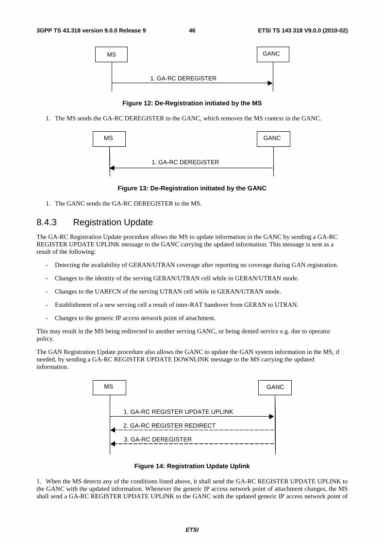
ETSI
ETSI TS 143 318 V9.0.0 (2010-02)463GPP TS 43.318 version 9.0.0 Release 9
GANC MS
1. GA-RC DEREGISTER
Figure 12: De-Registration initiated by the MS
1. The MS sends the GA-RC DEREGISTER to the GANC, which removes the MS context in the GANC.
GANC MS
1. GA-RC DEREGISTER
Figure 13: De-Registration initiated by the GANC
1. The GANC sends the GA-RC DEREGISTER to the MS.
8.4.3 Registration Update
The GA-RC Registration Update procedure allows the MS to update information in the GANC by sending a GA-RC REGISTER UPDATE UPLINK message to the GANC carrying the updated information. This message is sent as a result of the following:
- Detecting the availability of GERAN/UTRAN coverage after reporting no coverage during GAN registration.
- Changes to the identity of the serving GERAN/UTRAN cell while in GERAN/UTRAN mode.
- Changes to the UARFCN of the serving UTRAN cell while in GERAN/UTRAN mode.
- Establishment of a new serving cell a result of inter-RAT handover from GERAN to UTRAN.
- Changes to the generic IP access network point of attachment.
This may result in the MS being redirected to another serving GANC, or being denied service e.g. due to operator policy.
The GAN Registration Update procedure also allows the GANC to update the GAN system information in the MS, if needed, by sending a GA-RC REGISTER UPDATE DOWNLINK message to the MS carrying the updated information.
GANC MS
1. GA-RC REGISTER UPDATE UPLINK
2. GA-RC REGISTER REDIRECT
3. GA-RC DEREGISTER
Figure 14: Registration Update Uplink
1. When the MS detects any of the conditions listed above, it shall send the GA-RC REGISTER UPDATE UPLINK to the GANC with the updated information. Whenever the generic IP access network point of attachment changes, the MS shall send a GA-RC REGISTER UPDATE UPLINK to the GANC with the updated generic IP access network point of

ETSI
ETSI TS 143 318 V9.0.0 (2010-02)473GPP TS 43.318 version 9.0.0 Release 9
attachment information. If the MS requires to update the GANC with a new list of GAN Services required, then the MS sends GA-RC REGISTER UPDATE UPLINK message to the GANC including the new GAN Services Required list.
2. The GANC may optionally send the GA-RC REGISTER REDIRECT when it wants to redirect the MS based on updated information.
3. The GANC may also optionally deregister the MS on receiving an update by sending GA-RC DEREGISTER to the MS.
GANC MS
1. GA-RC REGISTER UPDATE DOWNLINK
Figure 15: Registration Update Downlink
1. The GANC sends GA-RC REGISTER UPDATE DOWNLINK with the updated system information.
8.4.4 Keep Alive
The Keep Alive process is a mechanism between the peer GA-RC entities to indicate that the MS is still registered to the GANC. Using periodic transmissions of the GA-RC KEEP ALIVE message the MS in turn determines that the GANC is still available using the currently established lower layer connection.
GANC MS
1. GA-RC KEEP ALIVE
Figure 16: Keep Alive procedure
1. The MS sends GA-RC KEEP ALIVE to the GANC.
8.4.5 Cell Broadcast Information
The Cell Broadcast Information is a mechanism between the peer GA-RC entities, allowing the GANC to pass the MS information relating to the Cell Broadcast Services. The MS includes GAN Service Required information in the GA-RC REGISTER REQUEST and GA-RC REGISTER UPDATE UPLINK messages passed to the GANC, indicating that the MS requires the Cell Broadcast Service. The GANC then passes the required information to the MS in the GA-RC CELL BROADCAST INFO message.
GANC MS
1. GA-RC CELL BROADCAST INFO
GANC MS
Figure 16a: Cell Broadcast Information
1. The GANC sends the CELL BROADCAST INFO message to the MS, including information required by the MS.

ETSI
ETSI TS 143 318 V9.0.0 (2010-02)483GPP TS 43.318 version 9.0.0 Release 9
8.5 Authentication The Up interface shall support the ability to authenticate the MS with the GANC (for the purposes of establishing the secure tunnel) using GSM or UMTS credentials. Authentication between MS and GANC shall be performed using EAP-SIM or EAP-AKA within IKEv2.
The MS and GANC-SEGW establish a secure association for protecting signalling traffic and user-plane (voice and data) traffic. The protocol for authentication is IKEv2. Mutual authentication and key generation is provided by EAP-SIM or EAP-AKA.
The basic elements of these procedures are the following:
• The MS connection with the GANC-SEGW is initiated by starting the IKEv2 initial exchanges (IKE_SA_INIT). The EAP-SIM or EAP-AKA procedure is started as a result of these exchanges.
• The EAP-SIM procedure for MS with SIM only or MS with USIM, but not capable of UMTS AKA, is performed between MS and AAA server (that has access to the AuC/HLR/HSS to retrieve subscriber information). The EAP-AKA procedure for MS with USIM and the MS is capable of UMTS AKA, is performed between MS and AAA server. The GANC-SEGW acts as relay for the EAP-SIM/EAP-AKA messages.
• When the EAP-SIM/EAP-AKA procedure has completed successfully, the IKEv2 procedure can be continued to completion and the signalling channel between MS and GANC-SEGW is secured. The MS and GAN can then continue with the discovery or registration procedure.
• Signalling flows for EAP-SIM and EAP-AKA authentication and fast re-authentication are shown in annex A.
8.6 Encryption All control and user plane traffic over the Up interface shall be sent through the IPsec tunnel that is established as a result of the authentication procedure. Encryption shall use the negotiated cryptographic algorithm, based on core network policy, enforced by the GANC-SEGW.
The MS and GANC-SEGW set up one Secure Association through which all traffic is sent. A single negotiated ciphering algorithm is applied to the connection.
8.6.1 Establishment of a Secure Association
After the authentication procedure (clause 8.5), the MS shall request an IP address on the network protected by the GANC-SEGW (i.e. the public IP interface of the GANC). The MS shall set up one IPsec Security Association (SA) between MS and GANC-SEGW.
The MS shall initiate the creation of the SA i.e. it shall act as initiator in the Traffic Selector negotiation. The protocol ID field in the Traffic Selectors (TS) shall be set to zero, indicating that the protocol ID is not relevant. The IP address range in the TSi shall be set to the address assigned to the MS (within the network protected by the GANC-SEGW). The IP address range in the TSr shall be set to 0.0.0.0 - 255.255.255.255. The MS and GANC-SEGW shall use the IKEv2 mechanisms for detection of NAT, NAT traversal and keep-alive.
All control and user plane data over the Up interface between MS and GANC shall be sent through the SA.
The ciphering mode is negotiated during connection establishment. During setup of the SA, the MS includes a list of supported encryption algorithms as part of the IKE signalling, which include the mandatory and supported optional algorithms defined in the IPsec profile, and NULL encryption. The GANC-SEGW selects one of these algorithms, and signals this to the MS.
When NULL encryption is applied, both control and user-plane traffic is sent unencrypted. This configuration can be selected e.g. when the connection between the generic IP access network and the GANC is under operator control. The integrity algorithm is the same as for either configuration i.e. non-ciphered traffic is still integrity protected.

ETSI
ETSI TS 143 318 V9.0.0 (2010-02)493GPP TS 43.318 version 9.0.0 Release 9
8.7 GA-CSR Connection handling The GA-CSR connection is a logical connection between the MS and the GANC for the CS domain. It is established when the upper layers in the MS request GA-CSR to enter dedicated mode. When a successful response is received from the network, GA-CSR replies to the upper layer that it has entered dedicated mode. The upper layers have then the possibility to request transmission of NAS messages to the network.
8.7.1 GA-CSR Connection Establishment
Figure 17 shows successful establishment of the GA-CSR Connection.
MS GANC CN
2. GA-CSR REQUEST ACCEPT
1. GA-CSR REQUEST (Establishment Cause)
3. GA-CSR REQUEST REJECT (Cause)
Figure 17: GA-CSR Connection Establishment
1. The MS initiates GA-CSR connection establishment by sending the GA-CSR REQUEST message to the GANC. This message contains the Establishment Cause indicating the reason for GA-CSR connection establishment.
2. GANC signals the successful response to the MS by sending the GA-CSR REQUEST ACCEPT and the MS enters dedicated mode and the GA-CSR state changes to GA-CSR-DEDICATED.
3. Alternatively, the GANC may return a GA-CSR REQUEST REJECT indicating the reject cause.
8.7.2 GA-CSR Connection Release
Figure 18 shows release of the logical GA-CSR connection between the MS and the GANC.
MS GANC CN
3. GA-CSR RELEASE
4. GA-CSR RELEASE COMPLETE
1. Clear Command
2. Clear Complete
Figure 18: GA-CSR Connection Release
1. The CN indicates to the GANC to release the user plane connection allocated to the MS, via the Clear Command.
2. The GANC confirms resource release to CN using the Clear Complete message.
3. The GANC commands the MS to release resources, using the GA-CSR RELEASE message.
4. The MS confirms resource release to the GANC using the GA-CSR RELEASE COMPLETE message and the MS enters idle mode and the GA-CSR state in the MS changes to GA-CSR-IDLE.

ETSI
ETSI TS 143 318 V9.0.0 (2010-02)503GPP TS 43.318 version 9.0.0 Release 9
8.8 Ciphering Configuration The message flow for ciphering configuration is shown in figure 19.
MS GANC CN
1. Cipher Mode Command
3. GA-CSR CIPHERING MODE COMPLETE (MAC(rand, ...), (IMEISV))
4. Cipher Mode Complete
2. GA-CSR CIPHERING MODE COMMAND (algorithm, cipher response, rand, ...)
Verify MAC
Figure 19: Ciphering Configuration
1. The CN sends BSSMAP "Cipher Mode Command" message to GANC. This message contains the cipher key Kc, and the encryption algorithms that the GANC may use.
2. The GANC sends GA-CSR CIPHERING MODE COMMAND to the MS. This message indicate whether stream ciphering shall be started or not (after handover to GERAN) and if so, which algorithm to use, and a random number. The mobile station stores the information for possible future use after a handover to GERAN. The message also indicates whether the MS shall include IMEISV in the GA-CSR CIPHERING MODE COMPLETE message.
3. The MS computes a MAC based on the random number, the MS IMSI and the key Kc. The MS then sends GA-CSR CIPHERING MODE COMPLETE message to signal its selected algorithm, the computed MAC, and the IMEISV, if indicated so in the GA-CSR CIPHERING MODE COMMAND.
4. This GANC verifies the MAC. If the GANC verifies MAC to be correct it sends Cipher Mode Complete message to the CN.
NOTE: The MAC proves that the identity that is authenticated to the GANC is the same as the identity authenticated to the core network. The configuration option of not enabling ciphering in the network will therefore open up the network to more security threats than in GERAN.
8.9 GA-CSR Signalling and SMS Transport Procedures
8.9.1 Network initiated CS Signalling
MS GANC CN
2. GA-CSR DL DIRECT TRANSFER (Layer 3 message)
1. DTAP(Layer 3 message)
Figure 20: Downlink Control Plane Transport
1. For Network initiated signalling/SMS, the Core Network sends a MM/CC signalling or SMS message to the GANC via the A interface.
2. The GANC encapsulates the received message within a GA-CSR DL DIRECT TRANSFER message that is forwarded to the MS via the existing TCP connection.
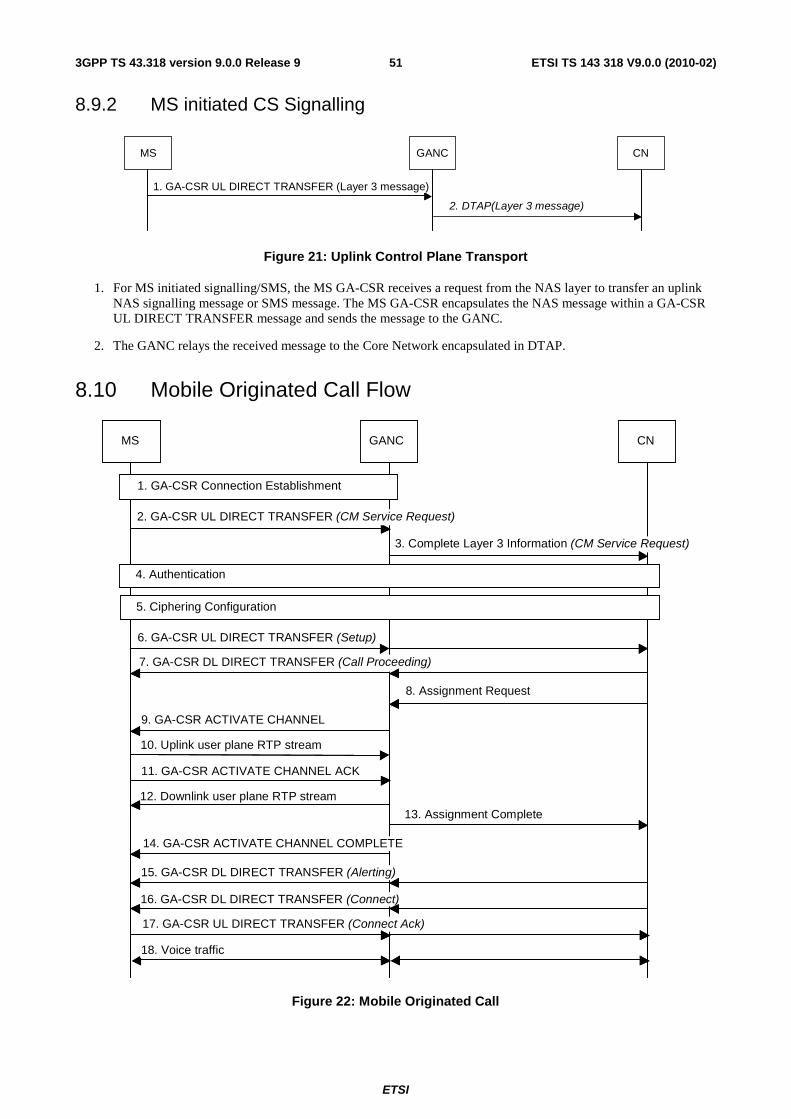
ETSI
ETSI TS 143 318 V9.0.0 (2010-02)513GPP TS 43.318 version 9.0.0 Release 9
8.9.2 MS initiated CS Signalling
MS GANC CN
1. GA-CSR UL DIRECT TRANSFER (Layer 3 message)
2. DTAP(Layer 3 message)
Figure 21: Uplink Control Plane Transport
1. For MS initiated signalling/SMS, the MS GA-CSR receives a request from the NAS layer to transfer an uplink NAS signalling message or SMS message. The MS GA-CSR encapsulates the NAS message within a GA-CSR UL DIRECT TRANSFER message and sends the message to the GANC.
2. The GANC relays the received message to the Core Network encapsulated in DTAP.
8.10 Mobile Originated Call Flow
MS GANC CN
3. Complete Layer 3 Information (CM Service Request)
6. GA-CSR UL DIRECT TRANSFER (Setup)
7. GA-CSR DL DIRECT TRANSFER (Call Proceeding)
8. Assignment Request
9. GA-CSR ACTIVATE CHANNEL
10. Uplink user plane RTP stream
11. GA-CSR ACTIVATE CHANNEL ACK
12. Downlink user plane RTP stream
13. Assignment Complete
14. GA-CSR ACTIVATE CHANNEL COMPLETE
15. GA-CSR DL DIRECT TRANSFER (Alerting)
16. GA-CSR DL DIRECT TRANSFER (Connect)
17. GA-CSR UL DIRECT TRANSFER (Connect Ack)
18. Voice traffic
2. GA-CSR UL DIRECT TRANSFER (CM Service Request)
1. GA-CSR Connection Establishment
4. Authentication
5. Ciphering Configuration
Figure 22: Mobile Originated Call
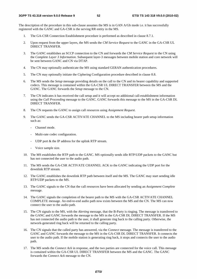
ETSI
ETSI TS 143 318 V9.0.0 (2010-02)523GPP TS 43.318 version 9.0.0 Release 9
The description of the procedure in this sub-clause assumes the MS is in GAN A/Gb mode i.e. it has successfully registered with the GANC and GA-CSR is the serving RR entity in the MS.
1. The GA-CSR Connection Establishment procedure is performed as described in clause 8.7.1.
2. Upon request from the upper layers, the MS sends the CM Service Request to the GANC in the GA-CSR UL DIRECT TRANSFER.
3. The GANC establishes an SCCP connection to the CN and forwards the CM Service Request to the CN using the Complete Layer 3 Information. Subsequent layer-3 messages between mobile station and core network will be sent between GANC and CN via DTAP.
4. The CN may optionally authenticate the MS using standard GERAN authentication procedures.
5. The CN may optionally initiate the Ciphering Configuration procedure described in clause 8.8.
6. The MS sends the Setup message providing details on the call to the CN and its bearer capability and supported codecs. This message is contained within the GA-CSR UL DIRECT TRANSFER between the MS and the GANC. The GANC forwards the Setup message to the CN.
7. The CN indicates it has received the call setup and it will accept no additional call-establishment information using the Call Proceeding message to the GANC. GANC forwards this message to the MS in the GA-CSR DL DIRECT TRANSFER.
8. The CN requests the GANC to assign call resources using Assignment Request.
9. The GANC sends the GA-CSR ACTIVATE CHANNEL to the MS including bearer path setup information such as:
- Channel mode.
- Multi-rate codec configuration.
- UDP port & the IP address for the uplink RTP stream.
- Voice sample size.
10. The MS establishes the RTP path to the GANC. MS optionally sends idle RTP/UDP packets to the GANC but has not connected the user to the audio path.
11. The MS sends the GA-CSR ACTIVATE CHANNEL ACK to the GANC indicating the UDP port for the downlink RTP stream.
12. The GANC establishes the downlink RTP path between itself and the MS. The GANC may start sending idle RTP/UDP packets to the MS.
13. The GANC signals to the CN that the call resources have been allocated by sending an Assignment Complete message.
14. The GANC signals the completion of the bearer path to the MS with the GA-CSR ACTIVATE CHANNEL COMPLETE message. An end-to-end audio path now exists between the MS and the CN. The MS can now connect the user to the audio path.
15. The CN signals to the MS, with the Alerting message, that the B-Party is ringing. The message is transferred to the GANC and GANC forwards the message to the MS in the GA-CSR DL DIRECT TRANSFER. If the MS has not connected the audio path to the user, it shall generate ring back to the calling party. Otherwise, the network-generated ring back will be returned to the calling party.
16. The CN signals that the called party has answered, via the Connect message. The message is transferred to the GANC and GANC forwards the message to the MS in the GA-CSR DL DIRECT TRANSFER. It connects the user to the audio path. If the mobile station is generating ring back, it stops and connects the user to the audio path.
17. The MS sends the Connect Ack in response, and the two parties are connected for the voice call. This message is contained within the GA-CSR UL DIRECT TRANSFER between the MS and the GANC. The GANC forwards the Connect Ack message to the CN.

ETSI
ETSI TS 143 318 V9.0.0 (2010-02)533GPP TS 43.318 version 9.0.0 Release 9
18. Bi-directional voice traffic flows between the MS and CN through the GANC.
8.11 Mobile Terminated Call Flow
GANC
1. Paging
2. GA-CSR PAGING REQUEST
3. GA-CSR PAGING RESPONSE 4. Complete L3 Info (Paging Response)
7. GA-CSR DL DIRECT TRANSFER (Setup)
8. GA-CSR UL DIRECT TRANSFER (Call Confirmed)
12. GA-CSR DL DIRECT TRANSFER (Connect Ack)
10. GA-CSR UL DIRECT TRANSFER (Alerting)
13. Voice traffic
9. RTP stream setup Assignment procedure
11. GA-CSR UL DIRECT TRANSFER (Connect)
MS CN
5. Authentication
6. Ciphering Configuration
Figure 23: Mobile Terminated Call
The description of the procedure in this clause assumes the MS is in GAN A/Gb mode i.e. it has successfully registered with the GANC and GA-CSR is the serving RR entity in the MS.
1. A mobile-terminated call arrives at the CN. The CN sends a Paging message to the GANC identified through the last Location Update received by it and includes the TMSI if available. The IMSI of the mobile being paged is always included in the request.
2. GANC identifies the MS registration context using the IMSI provided by the CN. It then pages the MS using the GA-CSR PAGING REQUEST message. The message includes the TMSI, if available in the request from the CN, else it includes only the IMSI of the mobile.
3. The MS responds with a GA-CSR PAGING RESPONSE including the MS Classmark and ciphering key sequence number. The MS enters dedicated mode and the GA-CSR state changes to GA-CSR-DEDICATED.
4. The GANC establishes an SCCP connection to the CN. The GANC then forwards the paging response to the CN using the Complete Layer 3 Information message.
5. The CN may optionally authenticate the MS using standard GERAN authentication procedures.
6. The CN may optionally update the ciphering configuration in the MS, via the GANC, as described in clause 8.8.
7. The CN initiates call setup using the Setup message sent to the MS via GANC. GANC forwards this message to the MS in the GA-CSR DL DIRECT TRANSFER message.
8. The MS responds with Call Confirmed using the GA-CSR UL DIRECT TRANSFER after checking it's compatibility with the bearer service requested in the Setup and modifying the bearer service as needed. If the Setup included the signal information element, the MS alerts the user using the indicated signal, else the MS alerts the user after the successful configuration of the user plane. The GANC forwards the Call Confirmed message to the CN.

ETSI
ETSI TS 143 318 V9.0.0 (2010-02)543GPP TS 43.318 version 9.0.0 Release 9
9. The CN initiates the assignment procedure with the GANC, which triggers the setup of the RTP stream (voice bearer channel) between the GANC and MS, same as steps 8-13 in MO call scenario.
10. The MS signals that it is alerting the user, via the Alerting message contained in the GA-CSR UL DIRECT TRANSFER. The GANC forwards the Alerting message to the CN. The CN sends a corresponding alerting message to the calling party.
11. The MS signals that the called party has answered, via the Connect message contained in the GA-CSR UL DIRECT TRANSFER. The GANC forwards the Connect message to the CN. The CN sends a corresponding Connect message to the calling party and through connects the audio. The MS connects the user to the audio path.
12. The CN acknowledges via the Connect Ack message to the GANC. GANC forwards this message to the MS in the GA-CSR DL DIRECT TRANSFER. The two parties on the call are connected on the audio path.
13. Bi-directional voice traffic flows between the MS and CN through the GANC.
8.12 Call Clearing Figure 24 shows call clearing initiated by the mobile station.
GANC CN MS
2. GA-CSR DL DIRECT TRANSFER (Release)
1. GA-CSR UL DIRECT TRANSFER (Disconnect)
3. GA-CSR UL DIRECT TRANSFER (Release Complete)
4. GA-CSR Connection Release
Figure 24: Mobile Station initiated Call clearing
1. The MS sends the Disconnect message to the CN to release the call. This message is contained in the GA-CSR UL DIRECT TRANSFER message between MS and GANC. The GANC forwards the Disconnect message to the CN.
2. The CN responds with a Release message to the GANC. The GANC forwards this message to the MS using the GA-CSR DL DIRECT TRANSFER message.
3. The MS responds with the Release Complete message. This message is contained within the GA-CSR UL DIRECT TRANSFER message between MS and GANC. The GANC forwards the Disconnect message to the CN.
4. The CN triggers the release of connection as described in clause 8.7.2.
8.13 Channel Modify
The GANC may use the Channel Modify procedures to modify parameters used for an ongoing call, this procedure may be used if coding scheme should be changed, in fault or congestion situations if the GANC for example detects "packet loss" and Handover to another GERAN/UTRAN mode is not possible or desired.
The GANC may modify the following parameters:
• Channel mode.
• Sample Size.
• IP address.
• RTP UDP port.

ETSI
ETSI TS 143 318 V9.0.0 (2010-02)553GPP TS 43.318 version 9.0.0 Release 9
• RTCP UDP port.
MS GANC CN
2. GA-CSR CHANNEL MODE MODIFY
3. GA-CSR CHANNEL MODE MODIFY ACKNOWLEDGE
1. Call establishment
Figure 25: Channel Mode Modify
1. A call is established as described in clauses 8.10 or 8.11.
2. The GANC sends the GA-CSR CHANNEL MODE MODIFY message to the MS to modify parameters for the established call.
3. The MS responds with the GA-CSR CHANNEL MODE MODIFY ACKNOWLEDGE message to the GANC.
8.14 CS Handover between GAN A/Gb mode and GERAN/UTRAN mode
8.14.1 CS Handover to GAN A/Gb mode
8.14.1.1 GERAN to GAN CS Handover

ETSI
ETSI TS 143 318 V9.0.0 (2010-02)563GPP TS 43.318 version 9.0.0 Release 9
MS GANC CN BSC
3. Handover Request
7. GA-CSR HANDOVER ACCESS
4. Handover Request Acknowledge
11. Voice traffic
8. RTP stream setup
1. Um: Measurement Report
2. Handover Required
5. Handover Command 6. Um: Handover Command
9. GA-CSR HANDOVER COMPLETE
10. Handover Detect
12. Handover Complete
13. Clear Command
14. Clear Complete
GAN Registered
Figure 26: GERAN to GAN CS Handover
The description of the GERAN to GAN CS handover procedure assumes the following:
• the MS is on an active call on the GERAN; and
• its mode selection is GAN-preferred, or if GERAN/UTRAN-preferred the RxLev from the current serving cell drops below a MS implementation specific threshold; and
• the MS has successfully registered with a GANC, allowing the MS to obtain GAN system information; and
• the GERAN provides information on neighbouring cells such that one of the {ARFCN, BSIC} in the neighbour list matches the {ARFCN, BSIC} associated with the GANC, as provided in the AS-related component of the system information obtained from GANC.
1. The MS begins to include GAN cell information in the Measurement Report message to the GERAN. The MS reports the highest signal level for the GAN cell {ARFCN, BSIC}. This is not the actual measured signal level on GAN, rather an artificial value (i.e. RxLev = 63), allowing the MS to indicate preference for the GAN.
2. Based on MS measurement reports and other internal algorithms, GERAN decides to handover to the GAN cell, using an internal mapping of {ARFCN, BSIC} to CGI. The GERAN starts the handover preparation by sending a Handover Required message to the CN, identifying the target (GAN) cell.
3. The CN requests the target GANC to allocate resources for the handover, using Handover Request message.
4. The target GANC acknowledges the Handover Request message, using Handover Request Acknowledge message, indicating it can support the requested handover, and provides a Handover Command message that indicates the radio channel to which the mobile station should be directed.
5. The CN forwards the Handover Command message to the GERAN, completing the handover preparation.
6. GERAN sends Handover Command message to the MS to initiate handover to GAN. The Handover Command message includes among other parameters information about the target GAN such as BCCH ARFCN, PLMN colour code and BSIC. The MS does not switch its audio path from GERAN to GAN until handover

ETSI
ETSI TS 143 318 V9.0.0 (2010-02)573GPP TS 43.318 version 9.0.0 Release 9
completion, i.e. until it sends the GA-CSR HANDOVER COMPLETE message, to keep the audio interruption short.
7. The MS accesses the GANC using the GA-CSR HANDOVER ACCESS message, and provides the entire Handover Command message received from GERAN. Information in the Handover Command message (e.g. Handover Reference) allows the GANC to correlate the handover to the Handover Request Acknowledge message earlier sent to the CN and identify the successful completion of the handover.
8. The GANC sets up the bearer path with the MS, using the same steps as in steps 9 to 14 of Mobile Originated Call Flow as defined in sub-clause 8.10.
9. The MS transmits the GA-CSR HANDOVER COMPLETE message to indicate the completion of the handover procedure at its end. It switches the user from the GERAN user plane to the GAN user plane.
10. The GANC indicates to the CN that it has detected the MS, using Handover Detect message. The CN can optionally now switch the user plane from the source GERAN to the target GAN.
11. Bi-directional voice traffic is now flowing between the MS and CN, via GANC.
12. The target GANC indicates the handover is complete, using the Handover Complete message. If it had not done so before, the CN now switches the user plane from source GERAN to target GAN. The CN may use the target CGI used in the Handover procedure for charging purposes.
13. Finally, the CN tears down the connection to the source GERAN, using Clear Command message.
14. The source GERAN confirms the release of GERAN resources allocated for this call, using Clear Complete message.
8.14.1.2 UTRAN to GAN CS Handover
MS GANC CN RNC
3. Handover Request
7. GA-CSR HANDOVER ACCESS
4. Handover Request Acknowledge
11. Voice traffic
8. RTP stream setup
1. Uu: Measurement Report
2. Relocation Required
5. Relocation Command
6. Uu: Handover from UTRAN command
9. GA-CSR HANDOVER COMPLETE
10. Handover Detect
12. Handover Complete
13. Iu Release Cmd
14. Iu Release Cmp
GAN Registered
Figure 26b: UTRAN to GAN CS Handover

ETSI
ETSI TS 143 318 V9.0.0 (2010-02)583GPP TS 43.318 version 9.0.0 Release 9
The description of the UTRAN to GAN CS Handover procedure assumes the following:
• the MS is on an active call on the UTRAN; and
• the MS has included the Support of Handover to GAN indication in the UE RAC; and
• the UE has been ordered by the RNC to make inter-RAT measurements, and
• if the MS is in GAN preferred mode with an Event 3A configured, the MS handles parameters associated with the Event 3A in a GAN specific manner (as described in 3GPP TS 44.318) for the reporting of the GAN cell {ARFCN, BSIC}; and
• when the UE is in GERAN/UTRAN preferred mode and an event 3A has been configured for the GAN cell (and possibly for GERAN cells), the UE shall only send a measurement about the GAN cell, when this event is triggered and no GERAN cells from the neighbour cell list of the UE satisfy the triggering condition of this Event (as described in 3GPP TS 25.331);
• the UTRAN provides information on neighbouring cells such that one of the {ARFCN, BSIC} in the neighbour list matches the {ARFCN, BSIC} associated with the GANC, as provided in the AS-related component of the system information obtained from GANC. The selection of the RF channel numbers (ARFCNs) used for the UTRAN to GAN handover procedure should not correspond to a channel from a frequency band supported by any UE, to avoid UEs that do not require compressed mode from unnecessarily powering up their GSM receivers.
1. The MS begins to include information about a GAN cell in the Measurement Report message sent to the RNC. The MS reports the highest signal level for the GAN cell {ARFCN, BSIC}. This is not the actual measured signal level on GAN, rather an artificial value (i.e., GSM carrier RSSI = 63) allowing the UE to indicate preference for the GAN.
2. Based on MS measurement reports and other internal algorithms, the RNC decides to initiate handover to the GAN cell, using an internal mapping of {ARFCN, BSIC} to CGI. The RNC starts the preparation phase of the Relocation procedure by sending a Relocation Required message to the CN, identifying the target (GAN) cell.
3. The CN requests the target GANC to allocate resources for the handover, using Handover Request message.
4. The target GANC acknowledges the handover request message, using Handover Request Acknowledge message, indicating it can support the requested handover, and including a Handover Command message that indicates the radio channel to which the mobile station should be directed.
5. The CN sends the Relocation Command message to the RNC, completing the relocation preparation.
6. The RNC sends HANDOVER FROM UTRAN COMMAND message to the MS to initiate handover to GAN. The HANDOVER FROM UTRAN COMMAND message includes the RR HANDOVER COMMAND message, specified in 44.018, which contains other parameters about the target GAN such as BCCH ARFCN, PLMN colour code and BSIC. The MS does not switch its audio path from UTRAN to GAN until handover completion, i.e. until it sends the GA-CSR HANDOVER COMPLETE message, to keep the audio interruption short.
7. The MS accesses the GANC using the GA-CSR HANDOVER ACCESS message, and provides the entire HANDOVER FROM UTRAN COMMAND received from RNC. The handover reference in the HANDOVER FROM UTRAN COMMAND message allows the GANC to correlate the handover to the Handover Request Acknowledge message earlier sent to the CN and identify the successful completion of the handover.
8. The GANC sets up the bearer path with the MS, using the same steps as in steps 9 to 14 of Mobile Originated Call Flow as defined in sub-clause 8.10.
9. The MS transmits the GA-CSR HANDOVER COMPLETE to indicate the completion of the handover procedure from its perspective. It switches the user from the UTRAN user plane to the GAN user plane.
10. The GANC indicates to the CN that it has detected the MS, using Handover Detect message. The CN can optionally now switch the user plane from the source RNC to the target GANC.
11. Bi-directional voice traffic is now flowing between the MS and CN, via GANC.

ETSI
ETSI TS 143 318 V9.0.0 (2010-02)593GPP TS 43.318 version 9.0.0 Release 9
12. The target GANC indicates the handover is complete, using the Handover Complete message. If it has not done so before, the CN now switches the user plane from source RNC to target GAN.
13. Finally, the CN tears down the connection to the source RNC, using Iu Release Command.
14. The source RNC confirms the release of UTRAN resources allocated for this call, using Iu Release Complete.
8.14.2 CS Handover from GAN A/Gb mode to GERAN
MS GANC MSC
Ongoing GAN
CS connection
3. Handover Required
BSS
8. Um: Handover Access
2. GA-CSR HANDOVER INFORMATION
7. GA-CSR HANDOVER COMMAND
6. Handover Command
14. Voice traffic
15. Release Command
17. Release Complete
1. GA-CSR UPLINK QUALITY INDICATION
4. Handover Request
5. Handover Request Ack
9. Handover Detect
12. Um: Handover Complete
13. Handover Complete
10. Voice
11. Um: Physical Information
18. GA-CSR RELEASE COMPLETE
16. GA-CSR RELEASE
19. GA-RC DEREGISTER
Figure 27: CS Handover from GAN A/Gb mode to GERAN
The procedure description in this sub-clause assumes the following:
• the MS is on an active call on the GAN A/Gb mode; and
• the GERAN becomes available; and
• the MS mode selection is GERAN/UTRAN-preferred; or
• the MS mode selection is GAN-preferred and the MS begins to leave GAN coverage, based on its local measurements, received RTCP reports, as well as any uplink quality indications received from the GANC.
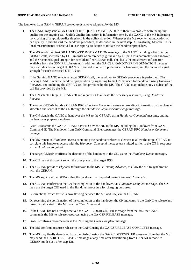
ETSI
ETSI TS 143 318 V9.0.0 (2010-02)603GPP TS 43.318 version 9.0.0 Release 9
The handover from GAN to GERAN procedure is always triggered by the MS.
1. The GANC may send a GA-CSR UPLINK QUALITY INDICATION if there is a problem with the uplink quality for the ongoing call. Uplink Quality Indication is information sent by the GANC to the MS indicating the crossing of a uplink quality threshold in the uplink direction. Whenever the MS receives an indication of bad quality, it should start the handover procedure, as described in the next step. Alternatively, MS can use its local measurements or received RTCP reports, to decide to initiate the handover procedure.
2. The MS sends the GA-CSR HANDOVER INFORMATION message to the GANC including a list of target GERAN cells, identified by CGI, in order of preference (e.g. ranked by C1 path loss parameter) for handover, and the received signal strength for each identified GERAN cell. This list is the most recent information available from the GSM RR subsystem. In addition, the GA-CSR HANDOVER INFORMATION message may include a list of target UTRAN cells ranked in order of preference for handover, and the received signal strength for each identified UTRAN cell.
3. If the Serving GANC selects a target GERAN cell, the handover to GERAN procedure is performed. The Serving GANC starts the handover preparation by signalling to the CN the need for handover, using Handover Required, and including the GERAN cell list provided by the MS. The GANC may include only a subset of the cell list provided by the MS.
4. The CN selects a target GERAN cell and requests it to allocate the necessary resources, using Handover Request.
5. The target GERAN builds a GERAN RRC Handover Command message providing information on the channel allocated and sends it to the CN through the Handover Request Acknowledge message.
6. The CN signals the GANC to handover the MS to the GERAN, using Handover Command message, ending the handover preparation phase.
7. GANC transmits the GA-CSR HANDOVER COMMAND to the MS including the Handover from GAN Command IE. The Handover from GAN Command IE encapsulates the GERAN RRC Handover Command message.
8. The MS transmits Handover Access containing the handover reference element to allow the target GERAN to correlate this handover access with the Handover Command message transmitted earlier to the CN in response to the Handover Required.
9. The target GERAN confirms the detection of the handover to the CN, using the Handover Detect message.
10. The CN may at this point switch the user plane to the target BSS.
11. The GERAN provides Physical Information to the MS i.e. Timing Advance, to allow the MS to synchronize with the GERAN.
12. The MS signals to the GERAN that the handover is completed, using Handover Complete.
13. The GERAN confirms to the CN the completion of the handover, via Handover Complete message. The CN may use the target CGI used in the Handover procedure for charging purposes.
14. Bi-directional voice traffic is now flowing between the MS and CN, via the GERAN.
15. On receiving the confirmation of the completion of the handover, the CN indicates to the GANC to release any resources allocated to the MS, via the Clear Command.
16. If the GANC has not already received the GA-RC DEREGISTER message from the MS, the GANC commands the MS to release resources, using the GA-CSR RELEASE message.
17. GANC confirms resource release to CN using the Clear Complete message.
18. The MS confirms resource release to the GANC using the GA-CSR RELEASE COMPLETE message.
19. The MS may finally deregister from the GANC, using the GA-RC DEREGISTER message. Note that the MS may send the GA-RC DEREGISTER message at any time after transitioning from GAN A/Gb mode to GERAN mode (i.e., after step 12).

ETSI
ETSI TS 143 318 V9.0.0 (2010-02)613GPP TS 43.318 version 9.0.0 Release 9
8.14.3 CS Handover from GAN A/Gb mode to UTRAN
MS GANC CN
Ongoing GAN
CS connection
3. Handover Required
RNS
8. Uu: UL Synchronization
2. GA-CSR HANDOVER INFORMATION
7. GA-CSR HANDOVER COMMAND
6. Handover Command
13. Voice traffic
14. Release Command
16. Release Complete
1. GA-CSR UPLINK QUALITY INDICATION
4. Relocation Request
5. Relocation Request Ack
9. Relocation Detect
12. Relocation Complete
10. Voice
11. Uu: Handover to UTRAN Complete
17. GA-CSR RELEASE COMPLETE
15. GA-CSR RELEASE
18. GA-RC DEREGISTER
Figure 28: CS Handover from GAN A/Gb mode to UTRAN
The procedure description in this sub-clause assumes the following:
• the MS is on an active call on the GAN A/Gb mode; and
• the MS is capable of operating in all of the GAN A/Gb, GERAN and UTRAN modes; and
• the UTRAN becomes available; and
• the MS is in GERAN/UTRAN-preferred mode; or
• the MS mode selection is GAN preferred and begins to leave GAN coverage, based on its local measurements, received RTCP reports, as well as any uplink quality indications received from the GANC.
The Inter-RAT handover from GAN procedure is always triggered by the MS.
1. The GANC may send a GA-CSR UPLINK QUALITY INDICATION if there is a problem with the uplink quality for the ongoing call. Uplink Quality Indication is information sent by the GANC to the MS indicating the crossing of a uplink quality threshold in the uplink direction. Whenever the MS receives an indication of bad quality, it should start the handover procedure, as described in the next step. Alternatively, MS can use its local measurements or received RTCP reports, to decide to initiate the handover procedure.

ETSI
ETSI TS 143 318 V9.0.0 (2010-02)623GPP TS 43.318 version 9.0.0 Release 9
2. The MS sends the GA-CSR HANDOVER INFORMATION message to the Serving GANC including a list of candidate target UTRAN and GERAN cells, in order of preference for handover, and includes the received signal strength for each identified cell. The UTRAN cells are identified by the PLMN ID, the LAC and the 3G Cell identity (defined in 3GPP TS 25.331 [40]).
NOTE: The choice of the candidate target UTRAN cells is out of the scope of this technical specification.
3. If the Serving GANC selects UTRAN as a target RAT, the inter-RAT handover procedure is performed. The Serving GANC starts the handover preparation by signaling to the CN the need for handover, using Handover Required and including the target RNC-ID that the GANC derives from the target UTRAN cell it selects from the list of candidate target UTRAN cells provided by the MS. The GANC may include only a single RNC-ID in the Handover Required message. The GANC also includes the Source RNC to Target RNC Transparent Container that contains the selected target UTRAN cell ID.
4. The CN starts the inter-RAT handover procedure towards the target RNC identified by the Serving GANC. The CN requests from the target RNS to allocate the necessary resources using Relocation Request.
5. The target UTRAN builds a UTRAN RRC Handover to UTRAN Command message providing information on the allocated UTRAN resources and sends it to the CN through the Relocation Request Acknowledge message.
6. The CN signals the Serving GANC to handover the MS to the UTRAN, using Handover Command message (which includes the UTRAN RRC Handover to UTRAN Command message), ending the handover preparation phase.
7. The Serving GANC transmits the GA-CSR HANDOVER COMMAND to the MS including the Handover from GAN Command IE. The Handover from GAN Command IE includes the GERAN RRC Inter System to UTRAN Handover Command message, which encapsulates the UTRAN RRC Handover to UTRAN Command message.
8. Target RNS achieves uplink synchronization on the Uu interface.
9. The target UTRAN confirms the detection of the handover to the CN, using the Relocation Detect message.
10. The CN may at this point switch the user plane to the target RNS.
11. The MS signals to the UTRAN that the handover is completed, using Handover to UTRAN Complete.
12. The UTRAN confirms to the CN the completion of the handover, via Relocation Complete message. If the user plane has not been switched in step 10, the CN switches the user plane to the target RNS.
13. Bi-directional voice traffic is now flowing between the MS and CN, via the UTRAN.
14. On receiving the confirmation of the completion of the handover, the CN indicates to the Serving GANC to release any resources allocated to the MS, via the Clear Command.
15. If the Serving GANC has not already received the GA-RC DEREGISTER message from the MS, the Serving GANC commands the MS to release resources, using the GA-CSR RELEASE message.
16. The Serving GANC confirms resource release to CN using the Clear Complete message.
17. The MS confirms resource release to the Serving GANC using the GA-CSR RELEASE COMPLETE message.
18. The MS may finally deregister from the Serving GANC, using GA-RC DEREGISTER message. Note that the MS may send the GA-RC DEREGISTER message at any time after transitioning from GAN A/Gb mode to UTRAN mode (i.e., after step 11).
8.15 Cell Change Order between GAN A/Gb mode and GERAN/UTRAN mode
While in GERAN/UTRAN, a mobile station may be ordered to perform a cell reselection to GAN A/Gb mode, by using the Cell Change Order procedures used in GERAN/UTRAN, with no modifications. The mobile station regards the procedure as completed when it has successfully performed Rove In to GAN.

ETSI
ETSI TS 143 318 V9.0.0 (2010-02)633GPP TS 43.318 version 9.0.0 Release 9
While the mobile station is involved in a PS session in the GAN A/Gb mode, there is no identified need for a Cell Change Order procedure.
8.16 GA-PSR Transport Channel Management Procedures
The GA-PSR Transport Channel (GA-PSR TC) management procedures are the basic GA-PSR procedures specified to facilitate the control of the GA-PSR connection for the user data transfer. A UDP based GA-PSR connection between the MS and the GANC for GPRS data transfer is referred to as the GA-PSR Transport Channel.
The GA-PSR Transport Channel consists of the following:
• The IP address and destination UDP port number to be used for GPRS data transfer at both the GANC and MS.
• The GA-PSR Channel Timer.
The MS or GANC will activate a GA-PSR Transport Channel only when needed; i.e. when the GPRS user data transfer is initiated.
The GA-PSR can be in two different states, GA-PSR-STANDBY or GA-PSR-ACTIVE state. The state of the GA-PSR and the corresponding transport channel are always synchronized.
• In GA-PSR-STANDBY state:
- The MS is not able to send or receive GPRS data to and from the GANC. The GANC or the MS needs to activate the GA-PSR Transport Channel before sending any GPRS data.
- A corresponding GA-PSR Transport Channel does not exist. When the GA-PSR Transport Channel is activated, the MS enters the GA-PSR-ACTIVE state.
• In GA-PSR-ACTIVE state:
- The MS is able to send and receive GPRS data to and from the GANC. Furthermore there exists a corresponding GA-PSR Transport Channel for this MS.
A GA-PSR Channel Timer is also defined to control the transition from GA-PSR-ACTIVE to GA-PSR-STANDBY state as follows:
• The MS GA-PSR layer implements a timer that is started when the MS enters GA-PSR-ACTIVE state and restarted each time a LLC-PDU is transmitted to or received from the network. When the timer expires, the MS deactivates the GA-PSR Transport Channel and the MS GA-PSR enters GA-PSR-STANDBY state.
The GA-PSR Channel Timer value is returned to the MS as part of the GAN Registration procedure (i.e. in GA-RC REGISTER ACCEPT message).
8.16.1 MS initiated Activation of GA-PSR Transport Channel
Figure 29 depicts the MS initiated GA-PSR Transport Channel activation procedure. The basic idea is that the GANC and MS can dynamically negotiate the IP address and UDP port numbers for data transfer. This procedure can facilitate the GANC load balancing; moreover, it allows the GANC to optimize the processing and maintain the context for active users only.

ETSI
ETSI TS 143 318 V9.0.0 (2010-02)643GPP TS 43.318 version 9.0.0 Release 9
GANC MS
1. GA-PSR ACTIVATE UTC REQ (MS UDP port)
2. GA-PSR ACTIVATE UTC ACK (GANC IP address, GANC UDP port)
3. GA-PSR UNITDATA (TLLI, PFI, priority, LLC-PDU)
4. GA-PSR UNITDATA (TLLI, PFI, LLC-PDU)
The uplink data transfer is initiated triggering the MS to activate GA-PSR TC
Figure 29: Activation of GA-PSR Transport Channel
Initially, the MS GA-PSR is in the GA-PSR-STANDBY state as the LLC layer requests the transfer of one or more uplink LLC-PDUs. As the MS GA-PSR is in GA-PSR-STANDBY state, the corresponding GA-PSR Transport Channel does not exist. This is a trigger for the MS to activate the GA-PSR Transport Channel (TC).
1. The GA-PSR-layer sends a GA-PSR ACTIVATE UTC REQ message to the GANC to request the activation of the GA-PSR Transport Channel. This message contains MS UDP port number that the GANC can use for the downlink transfer.
2. The GANC replies with a GA-PSR ACTIVATE UTC ACK message that contains the IP-address and the UDP port number to be used for the uplink user data transfer. Upon receiving the acknowledgment, the MS GA-PSR transitions to GA-PSR-ACTIVE state.
3. After successful GA-PSR TC activation, the MS forwards the LLC-PDU to the GANC IP-address and UDP-port received in the acknowledgment message using GA-PSR UNITDATA message. The GANC forwards the LLC-PDU and other parameters to the core network as per procedure described in clause 8.17.2.3 (not shown in the sequence). The MS restarts the GA-PSR Channel Timer.
4. The GANC receives a downlink user data message for the MS as per procedure described in clause 8.17.2.2 (not shown in the sequence) while the GA-PSR TC is still active. The LLC-PDU and the required parameters are sent to the MS encapsulated in a GA-PSR UNITDATA message using the associated GA-PSR Transport Channel information (MS IP-address and UDP-port received in step 1).
8.16.2 MS initiated Deactivation of the GA-PSR Transport Channel
The following message sequence depicts the scenario when the MS deactivates the GA-PSR Transport Channel after the GA-PSR Channel Timer expires. In addition, when a PS handover from GAN A/Gb mode to GERAN/UTRAN mode is successfully completed both the GANC and the MS shall consider the GA-PSR Transport Channel as implicitly deactivated and the MS shall stop the GA-PSR Channel Timer.
GANC MS
1. GA-PSR DEACTIVATE UTC REQ (Cause)
2. GA-PSR DEACTIVATE UTC ACK
GA-PSR Channel Timer expires
Figure 30: Deactivation of GA-PSR Transport Channel

ETSI
ETSI TS 143 318 V9.0.0 (2010-02)653GPP TS 43.318 version 9.0.0 Release 9
1. GA-PSR-layer in the MS sends the GA-PSR DEACTIVATE UTC REQ message to the GANC to request the deactivation of the GA-PSR Transport Channel. The message includes cause parameter to indicate "normal deactivation".
2. The GANC deletes the related MS information associated with the GA-PSR Transport Channel and replies to the MS with a GA-PSR DEACTIVATE UTC ACK message. Upon receiving the acknowledgment message, the MS enters GA-PSR-STANDBY state.
8.16.3 Implicit Deactivation of the GA-PSR Transport Channel due to MS Deregistration
When a GA-RC DEREGISTER message is received by the GANC or if the MS is implicitly deregistered, the GA-PSR Transport Channel associated with the MS, if any, is automatically released by the GANC.
8.16.4 Network initiated GA-PSR Transport Channel Activation
Figure 31 depicts a scenario when the GANC activates a GA-PSR Transport Channel for a GAN registered MS. This scenario covers the following cases:
� The GANC receives a downlink user data packet (LLC PDU) from the core network and the specified MS does not have an active GA-PSR Transport Channel.
� PS Handover to GAN A/Gb mode is initiated in support of one or more PS domain services.
GANC MS
2. GA-PSR ACTIVATE UTC ACK (MS UDP port)
1. GA-PSR ACTIVATE UTC REQ (GANC IP address, GANC UDP port)
4. GA-PSR UNITDATA (TLLI, PFI, priority, LLC-PDU)
3. GA-PSR UNITDATA (TLLI, PFI, LLC-PDU)
The downlink data transfer is initiated for an MS in
GA-PSR Standby state or PS Handover to GAN mode is initiated
Figure 31: Network initiated GA-PSR Transport Channel Activation
1. The GANC sends a GA-PSR ACTIVATE UTC REQ message to the MS to request the activation of the corresponding GA-PSR TC. The message contains the GANC IP address and UDP port number assigned to the GA-PSR TC and the MS GA-PSR transitions to GA-PSR-ACTIVE state.
2. The MS replies with a GA-PSR ACTIVATE UTC ACK message that contains the selected UDP-port number. Subsequently, the MS enters GA-PSR-ACTIVE state and starts the GA-PSR Channel Timer.
3. The GANC forwards the previously received downlink LLC-PDU to the MS using GA-PSR UNITDATA message as per procedure described in clause 8.17.1. For the case of PS handover to a GAN cell the reception of downlink LLC PDUs is enabled in the MS upon allocation of the GA-PSR Transport Channel in step 1.
4. The GA-PSR Transport Channel is active and the MS can send the uplink data using GA-PSR UNITDATA procedure described in clause 8.17.1. For the case of PS handover to a GAN cell the MS enables the transmission of uplink LLC PDUs on the allocated GA-PSR Transport Channel upon successful completion of the PS handover procedure.

ETSI
ETSI TS 143 318 V9.0.0 (2010-02)663GPP TS 43.318 version 9.0.0 Release 9
8.17 GPRS Data, Signalling and SMS Transport
8.17.1 GA-PSR GPRS Data Transport Procedures
Figure 32 illustrates the transport of GPRS user data messages via GAN.
GANC MS CN
2. GA-PSR UNITDATA (TLLI, PFI, priority, LLC-PDU)
5. GA-PSR UNITDATA (TLLI, PFI, LLC-PDU)
1. GA-PSR Transport Channel Activation
3. UL UNITDATA (..., LLC-PDU)
4. DL UNITDATA (..., LLC-PDU)
6. Additional GA-PSR user data transport
7. GA-PSR Transport Channel Deactivation
GA-PSR Channel Timer started
GA-PSR Channel Timer restarted
GA-PSR Channel Timer restarted
GA-PSR Channel Timer expires
Figure 32: User Plane Data Transport
1. Optionally, if the GA-PSR is in GA-PSR-STANDBY state, the GA-PSR Transport Channel is activated as per description in clauses 8.16.1 or 8.16.4. Upon successful activation, the MS starts the GA-PSR Channel Timer.
2. The MS encapsulates the uplink LLC-PDU within the GA-PSR UNITDATA message that is forwarded to the GANC. The message includes parameters required for Gb interface procedures and TLLI as MS identifier. The MS restarts the GA-PSR Channel Timer.
3. The GANC forwards the LLC-PDU to the Core Network as per standard Gb interface procedures.
4. The Core Network sends the downlink LLC-PDU that contains GPRS user data via the Gb interface. The MS is identified with the TLLI.
5. Assuming that the corresponding GPRS TC is available, the GANC forwards the LLC-PDU to the MS encapsulated in the GA-PSR UNITDATA message. Upon receiving this message, the MS restarts the GA-PSR Channel Timer.
6. The GPRS data transfer (steps 2 to 5), both in uplink and downlink direction, can be processed as many times as necessary while the GA-PSR TC is active.
7. When the GA-PSR Channel Timer expires, the corresponding GA-PSR TC is deactivated as per description in clause 8.16.2.
8.17.2 GA-PSR GPRS Signalling and SMS Transport Procedures
8.17.2.1 General
The TCP connection that is used for GA-CSR signalling is also used for GA-PSR GPRS signalling and SMS transport identified by LLC SAPI 1 and SAPI 7 respectively. This TCP connection is available after GAN registration, so establishment of a separate channel, i.e. a TCP connection, for GPRS signalling and SMS transport is not required.

ETSI
ETSI TS 143 318 V9.0.0 (2010-02)673GPP TS 43.318 version 9.0.0 Release 9
8.17.2.2 Network initiated GPRS Signalling
For Network initiated signalling/SMS, the Core Network sends a GMM/SM signalling or SMS message to the GANC via the Gb interface as per standard GPRS; e.g. the LLC PDU may include GMM attach accept or SM PDP context activation accept message. The GANC encapsulates the received LLC PDU within a GA-PSR DATA message that is forwarded to the MS via the existing TCP connection.
GANC MS CN
2. GA-PSR DATA (TLLI, PFI, LLC-PDU) 1. DL UNITDATA (..., LLC-PDU)
Figure 33: Downlink Control Plane Data Transport
1. The Core Network sends a GMM/SM signalling message or an SMS message as per GPRS via the Gb interface; e.g. the LLC-PDU may include GMM attach accept or SM PDP context activation accept message.
2. The GANC encapsulates the received LLC-PDU within a GA-PSR DATA message that is forwarded to the MS.
8.17.2.3 MS initiated GPRS Signalling
For MS initiated signalling/SMS, the MS GA-PSR receives a request from the LLC layer to transfer an uplink GMM/SM signalling message or SMS message; e.g. this could be a GMM attach request or SM PDP context activation message. The GMM/SM signalling messages are identified with LLC SAPI 1 and SMS messages with LLC SAPI 7. The MS GA-PSR encapsulates the LLC PDU within a GA-PSR DATA message including the parameters that will be required for Gb interface procedures. Subsequently, the message is forwarded to the GANC, and the GANC forwards the message to the Core Network as per standard Gb interface procedures.
GANC CN
1. GA-PSR DATA (TLLI, PFI, QoS, priority, LLC-PDU) 2. UL UNITDATA (..., LLC-PDU)
MS
Figure 34: Uplink Control Plane Data Transport
1. The MS GA-PSR receives a request from the LLC layer to transfer an uplink GMM/SM signalling message or SMS message; e.g. this could be a GMM attach request or SM PDP context activation message. The MS GA-PSR encapsulates the LLC-PDU within a GA-PSR DATA message including the parameters that will be required for Gb interface procedures. Subsequently, the message is forwarded to the GANC.
2. The GANC forwards the message to the Core Network as per standard Gb interface procedure.
8.18 GA-PSR Specific Signalling Procedures
8.18.1 Packet Paging for GPRS Data Service
The Core Network sends a PS page for a mobile station that is currently GPRS attached via the GAN.

ETSI
ETSI TS 143 318 V9.0.0 (2010-02)683GPP TS 43.318 version 9.0.0 Release 9
GANC MS CN
3. LLC-PDU Transport
2. GA-PSR PS PAGE (Mobile Identity)
4. UL UNITDATA (..., LLC-PDU)
1. PAGING PS
Figure 35: Packet Paging for GPRS
1. The Core Network sends a PAGING PS for a mobile station that is currently GPRS attached via the GAN. This message contains always IMSI and it may also contain P-TMSI.
2. GANC identifies the MS registration context using the IMSI provided by the CN and pages the MS using the GA-PSR PS PAGE message on the existing TCP signalling connection. The GA-PSR PS PAGE message on the Up interface includes the P-TMSI, if received in the PAGING PS message from the CN, else it includes the MS IMSI.
3. The mobile station sends any LLC-PDU to respond to the page, activating GA-PSR TC, if needed. The uplink LLC-PDU is forwarded to the GANC using the GPRS data or signalling transfer mechanism as described in clause 8.17.2.3.
4. The GANC forwards the LLC-PDU to the Core Network via the standard Gb interface procedures.
8.18.2 Packet Paging for CS Domain Service
The Core Network may send a CS page for a mobile station that is currently GPRS attached via the GAN.
GANC MS CN
3. GA-CSR PAGING RESPONSE
2. GA-CSR PAGING REQUEST
4. Paging Response
1. PAGING CS
Figure 36: Packet Paging for CS Service
1. The Core Network sends a PAGING CS for a GAN registered mobile station via the Gb interface. The mobile station is currently GPRS attached via the GAN. The PAGING CS message always contains IMSI as Mobile Identity and it may also contain TMSI.
2. GANC identifies the MS registration context using the IMSI provided by the CN and pages the MS using the GA-CSR PAGING REQUEST message on the existing TCP signalling connection. The GA-CSR PAGING REQUEST message on the Up interface includes the TMSI, if received in the PAGING CS message from the CN, else it includes the MS IMSI.
3-4. The mobile station initiates the standard CS page response procedure via the GAN as described in clause 8.11.
8.18.3 GPRS Suspend Procedure
The GPRS Suspend procedure is invoked if a mobile station is unable to support simultaneous voice and data services and is transitioning to dedicated mode.

ETSI
ETSI TS 143 318 V9.0.0 (2010-02)693GPP TS 43.318 version 9.0.0 Release 9
GANC MS CN
1. GA-CSR GPRS SUSPENSION REQUEST 2. SUSPEND procedure
Figure 37: GPRS Suspend
1. While transitioning to dedicated mode and if unable to support simultaneous voice and data services, the mobile station sends a GA-CSR GPRS SUSPENSION REQUEST message to the GANC to suspend downlink GPRS traffic. The request is transferred via the existing TCP signalling connection and includes TLLI and Suspension Cause parameters as per standard GPRS.
2. The GANC initiates and completes the standard GPRS Suspend procedure as defined for Gb interface.
8.18.4 GPRS Resume Procedure
If the GPRS service has been suspended while the mobile station entered the dedicated mode, it needs to be resumed when the mobile station leaves the dedicated mode.
GANC MS CN
4. GA-CSR RELEASE(GPRS resumption) 3. RESUME procedure
1. Clear Command
2. Clear Complete
5. GA-CSR RELEASE COMPLETE
6. Resume GPRS, if required
Figure 38: GPRS Resume
Initially, the MS is in the dedicated mode and the GPRS service is suspended.
1. The Core Network sends a Clear Command message to release the resources associated with the dedicated mode procedure.
2. The GANC responds with a Clear Complete message.
3. Optionally, the GANC may initiate the standard BSSGP GPRS resume procedure.
4. The GANC sends a GA-CSR RELEASE message to instruct the MS to release the GA-CSR Connection. The message includes GPRS resumption indication as per standard GSM/GPRS to indicate whether or not the network successfully resumed GPRS service.
5. The MS replies with a GA-CSR RELEASE COMPLETE message and resumes GPRS service internally.
6. Optionally, if the Core Network indicated unsuccessful resumption, the MS initiates GPRS service resumption as per standard GPRS.
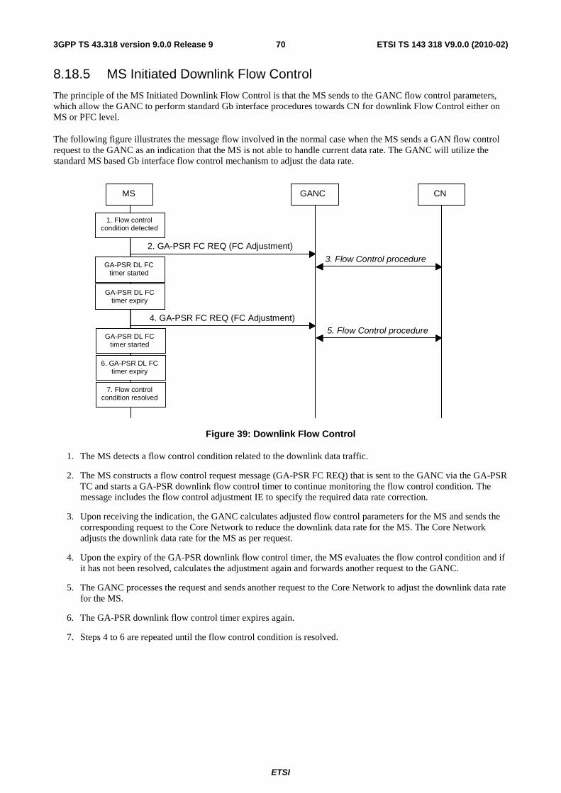
ETSI
ETSI TS 143 318 V9.0.0 (2010-02)703GPP TS 43.318 version 9.0.0 Release 9
8.18.5 MS Initiated Downlink Flow Control
The principle of the MS Initiated Downlink Flow Control is that the MS sends to the GANC flow control parameters, which allow the GANC to perform standard Gb interface procedures towards CN for downlink Flow Control either on MS or PFC level.
The following figure illustrates the message flow involved in the normal case when the MS sends a GAN flow control request to the GANC as an indication that the MS is not able to handle current data rate. The GANC will utilize the standard MS based Gb interface flow control mechanism to adjust the data rate.
GANC MS CN
3. Flow Control procedure
2. GA-PSR FC REQ (FC Adjustment)
5. Flow Control procedure 4. GA-PSR FC REQ (FC Adjustment)
1. Flow control condition detected
GA-PSR DL FC timer started
GA-PSR DL FC timer expiry
GA-PSR DL FC timer started
6. GA-PSR DL FC timer expiry
7. Flow control condition resolved
Figure 39: Downlink Flow Control
1. The MS detects a flow control condition related to the downlink data traffic.
2. The MS constructs a flow control request message (GA-PSR FC REQ) that is sent to the GANC via the GA-PSR TC and starts a GA-PSR downlink flow control timer to continue monitoring the flow control condition. The message includes the flow control adjustment IE to specify the required data rate correction.
3. Upon receiving the indication, the GANC calculates adjusted flow control parameters for the MS and sends the corresponding request to the Core Network to reduce the downlink data rate for the MS. The Core Network adjusts the downlink data rate for the MS as per request.
4. Upon the expiry of the GA-PSR downlink flow control timer, the MS evaluates the flow control condition and if it has not been resolved, calculates the adjustment again and forwards another request to the GANC.
5. The GANC processes the request and sends another request to the Core Network to adjust the downlink data rate for the MS.
6. The GA-PSR downlink flow control timer expires again.
7. Steps 4 to 6 are repeated until the flow control condition is resolved.
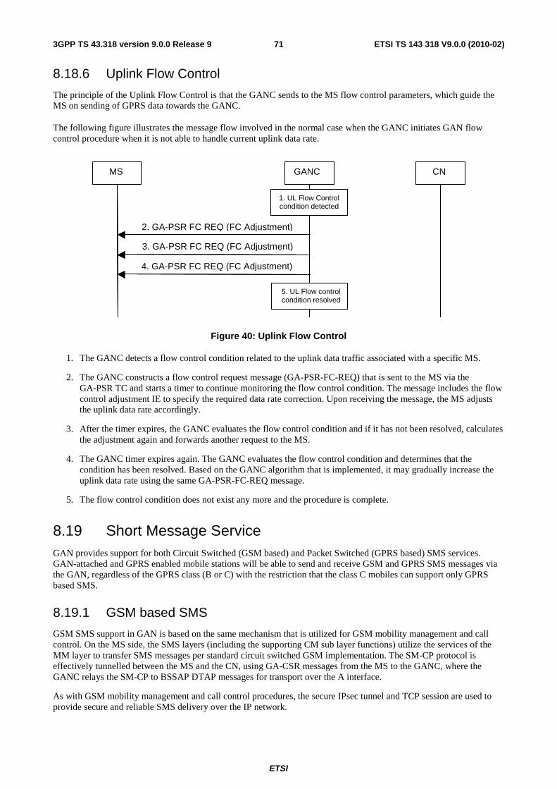
ETSI
ETSI TS 143 318 V9.0.0 (2010-02)713GPP TS 43.318 version 9.0.0 Release 9
8.18.6 Uplink Flow Control
The principle of the Uplink Flow Control is that the GANC sends to the MS flow control parameters, which guide the MS on sending of GPRS data towards the GANC.
The following figure illustrates the message flow involved in the normal case when the GANC initiates GAN flow control procedure when it is not able to handle current uplink data rate.
GANC MS CN
2. GA-PSR FC REQ (FC Adjustment)
1. UL Flow Control condition detected
3. GA-PSR FC REQ (FC Adjustment)
4. GA-PSR FC REQ (FC Adjustment)
5. UL Flow control condition resolved
Figure 40: Uplink Flow Control
1. The GANC detects a flow control condition related to the uplink data traffic associated with a specific MS.
2. The GANC constructs a flow control request message (GA-PSR-FC-REQ) that is sent to the MS via the GA-PSR TC and starts a timer to continue monitoring the flow control condition. The message includes the flow control adjustment IE to specify the required data rate correction. Upon receiving the message, the MS adjusts the uplink data rate accordingly.
3. After the timer expires, the GANC evaluates the flow control condition and if it has not been resolved, calculates the adjustment again and forwards another request to the MS.
4. The GANC timer expires again. The GANC evaluates the flow control condition and determines that the condition has been resolved. Based on the GANC algorithm that is implemented, it may gradually increase the uplink data rate using the same GA-PSR-FC-REQ message.
5. The flow control condition does not exist any more and the procedure is complete.
8.19 Short Message Service GAN provides support for both Circuit Switched (GSM based) and Packet Switched (GPRS based) SMS services. GAN-attached and GPRS enabled mobile stations will be able to send and receive GSM and GPRS SMS messages via the GAN, regardless of the GPRS class (B or C) with the restriction that the class C mobiles can support only GPRS based SMS.
8.19.1 GSM based SMS
GSM SMS support in GAN is based on the same mechanism that is utilized for GSM mobility management and call control. On the MS side, the SMS layers (including the supporting CM sub layer functions) utilize the services of the MM layer to transfer SMS messages per standard circuit switched GSM implementation. The SM-CP protocol is effectively tunnelled between the MS and the CN, using GA-CSR messages from the MS to the GANC, where the GANC relays the SM-CP to BSSAP DTAP messages for transport over the A interface.
As with GSM mobility management and call control procedures, the secure IPsec tunnel and TCP session are used to provide secure and reliable SMS delivery over the IP network.

ETSI
ETSI TS 143 318 V9.0.0 (2010-02)723GPP TS 43.318 version 9.0.0 Release 9
8.19.2 GPRS based SMS
GPRS SMS message transfer is based on the same mechanism as the transfer of the GPRS MM/SM signalling messages. On the MS side, the SMS layers (including the supporting CM sub layer functions) utilize the services of the LLC layer to transfer SMS messages per standard packet switched GPRS implementation.
As with GPRS signalling, the secure IPsec tunnel and TCP session is used to provide secure and reliable GPRS SMS delivery over the IP network.
8.20 Supplementary Services GSM has a large number of standardized supplementary services. These supplementary services involve procedures that operate end-to-end between the MS and the MSC. The DTAP messages used for the supplementary service are relayed between the MS and MSC in the same manner as in the other call control and mobility management scenarios described in this document.
8.21 Emergency Services
8.21.1 General
The GANC can indicate, in the GAN Registration procedures, an Access Network preference for the placement of emergency calls.
Based on the Access Network preference, and if any GERAN/UTRAN coverage is available (either from the GAN subscriber"s home PLMN or from any roamer PLMN, irrespective of roamer agreements), the MS should switch from GAN mode to GERAN/UTRAN mode and place the emergency call over GERAN/UTRAN, to leverage the location determination infrastructure in GERAN/UTRAN. During the emergency call, the MS should not attempt to handover the call to GAN. After the emergency call is completed, the MS may perform normal rove-in procedures to re-enter GAN mode, if GAN coverage is still available. Alternatively there may be a penalty timer configured to ensure that the MS remains in GERAN/UTRAN for call-back purposes. On expiry of the penalty timer the MS may perform normal rove-in procedures to re-enter GAN mode, if GAN coverage is still available.
Based on the Access Network preference, or if no GERAN/UTRAN coverage is available (neither from the GAN subscriber"s home PLMN nor from any roamer PLMN, irrespective of roamer agreements), the MS places the emergency call over GAN. In GAN, the emergency call is handled just like a GSM emergency call origination. The cell ID associated with the GANC provides an indication of the location of the MS. Additionally, more accurate location information may be obtained by the GANC either directly from the MS (e.g. using AGPS) or from the generic IP access network point of attachment (e.g. using a database of IP or MAC addresses). If available, the GANC can pass this location information through BSSMAP or RANAP signalling to the core network, when requested. However, location services based on mechanisms using the GERAN/UTRAN physical layer cannot be applied.
NOTE: A mechanism may be required in the GANC to force the MS to GERAN/UTRAN mode, if the location accuracy is not deemed sufficient for emergency calls in GAN mode.
8.21.2 North American Emergency Calls
8.21.2.1 Phase 1 Solution
8.21.2.1.1 Phase 1 Requirements
Wireless service providers were required by the FCC to have the capability to send wireless 911 calls to an E911 public safety answering point (PSAP) containing two important sets of data:
1. The location of the cell tower through which the E911 call was processed.
2. The mobile directory number (MDN) or "call back number" of the wireless phone placing the 911 call.

ETSI
ETSI TS 143 318 V9.0.0 (2010-02)733GPP TS 43.318 version 9.0.0 Release 9
8.21.2.1.2 Phase 1 Mechanism
The GANC shall indicate during registration, when entering GAN mode, whether GERAN/UTRAN or GAN is preferred for support of emergency calls.
• If GAN mode is the preferred emergency call mode, the emergency call shall be placed over GAN if the mobile is in GAN mode. The GANC can reject the call depending on operator policy.
• If GERAN/UTRAN mode is the preferred emergency mode, the emergency call shall be placed over the GERAN/UTRAN when a GERAN/UTRAN network is available. If a GERAN/UTRAN network is not available the emergency call shall be placed over GAN.
8.21.2.2 Phase 2 Solution
8.21.2.2.1 Phase 2 Requirements
Wireless service providers are required by the FCC to have the ability to provide the actual caller's location to the E911 PSAP. The location accuracy requirements differ depending on whether a network-based or handset-based approach is chosen.
• Network-based requirement: Within 100 meters, 67% of the time and within 300 meters, 95% of the time.
• Handset-based requirement: Within 50 meters, 67% of the time and within 150 meters, 95% of the time.
The handset-based requirements apply to terminals supporting location determining mechanisms (e.g. A-GPS, E-OTD). This may require new, modified or upgraded terminals.
8.21.2.2.2 Phase 2 Mechanism
The emergency call is placed over GERAN/UTRAN or GAN. If the emergency call is placed over GAN, the GANC will need to provide accurate location information for the MS or the AP through which the MS is placing the emergency call. This can be done in a number of ways:
• the GANC can reference an AP-ID to location mapping database for the GAN service;
• the MS can provide its current location (e.g. obtained via AGPS) in GA-RC REGISTER REQUEST/UPDATE message;
• the GANC can reference an MS (public) IP address to location mapping database;
• the GANC can deliver the required location information to the SMLC via Lb interface and the SMLC is responsible for final location determination.
The GANC passes this location information through BSSMAP or RANAP signalling to the CN, when requested.
8.22 Location Services The GANC uses information received from the MS during the GAN Registration and GAN Registration Update procedures to determine the geographic location of an MS.
1. Cell-Info: The MS provides the identity of the GSM or UTRAN cell it is camped on, in case GERAN/UTRAN coverage is available, at the time of GAN registration. The GANC determines the MS location to the resolution of a single cell. This enables location services that require location resolution provided by a cell (e.g. E911 Phase 1).
NOTE 1: The accuracy of the location may be reduced if no up-to-date cellular coverage information is available.

ETSI
ETSI TS 143 318 V9.0.0 (2010-02)743GPP TS 43.318 version 9.0.0 Release 9
2. Generic IP access network point of attachment information (AP-ID): The MS provides the AP-ID at the time of GAN registration. The GANC may maintain an internal database of mapping between AP-ID and AP location. The AP Location may be defined as street address, postcode or zip code and would require a translation function to a GAD shape as defined in 3GPP TS 23.032 [41]. The GANC may then determine the MS location to the resolution of a single attachment point's coverage area. This can enable location services that require a location with greater resolution than that provided by a GSM cell (e.g. E911 Phase 2).
NOTE 2: The location of the point of attachment may not be reliable, and is dependent on up-to-date information being provided either by the MS or by the owner of the point of attachment.
8.23 PS Handovers between GAN A/Gb mode and GERAN/UTRAN mode
Procedures for PS handover between GERAN/UTRAN mode and GAN A/Gb mode when an MS and BSS/RNC/GANC support this type of PS handover are described in 3GPP TS 43.129 [44].
9 High-Level Procedures for GAN Iu Mode
9.1 Mechanism of Mode Selection in Multi-mode terminals See clause 8.1.
9.2 PLMN Selection See clause 8.2.
9.3 Re-selection between GERAN/UTRAN and GAN modes See clause 8.3.
9.4 GAN Discovery and Registration related procedures See clause 8.4.
9.5 Authentication See clause 8.5.
9.6 Encryption See clause 8.6.
9.7 GA-RRC Connection handling The GAN Iu mode GA-RRC CS and PS connections are logical connections between the MS and the GANC.
A GA-RRC connection is established when the upper layers in the MS request the establishment of a signalling connection for either CS or PS domain and the MS is in GA-RRC-IDLE state for that domain; i.e., no GA-RRC connection exists. When a successful response is received from the network, GA-RRC replies to the upper layer that the MS has entered the RRC connected mode (i.e., the GA-RRC-CONNECTED state). The upper layers then have the possibility to request transmission of NAS messages to the network.
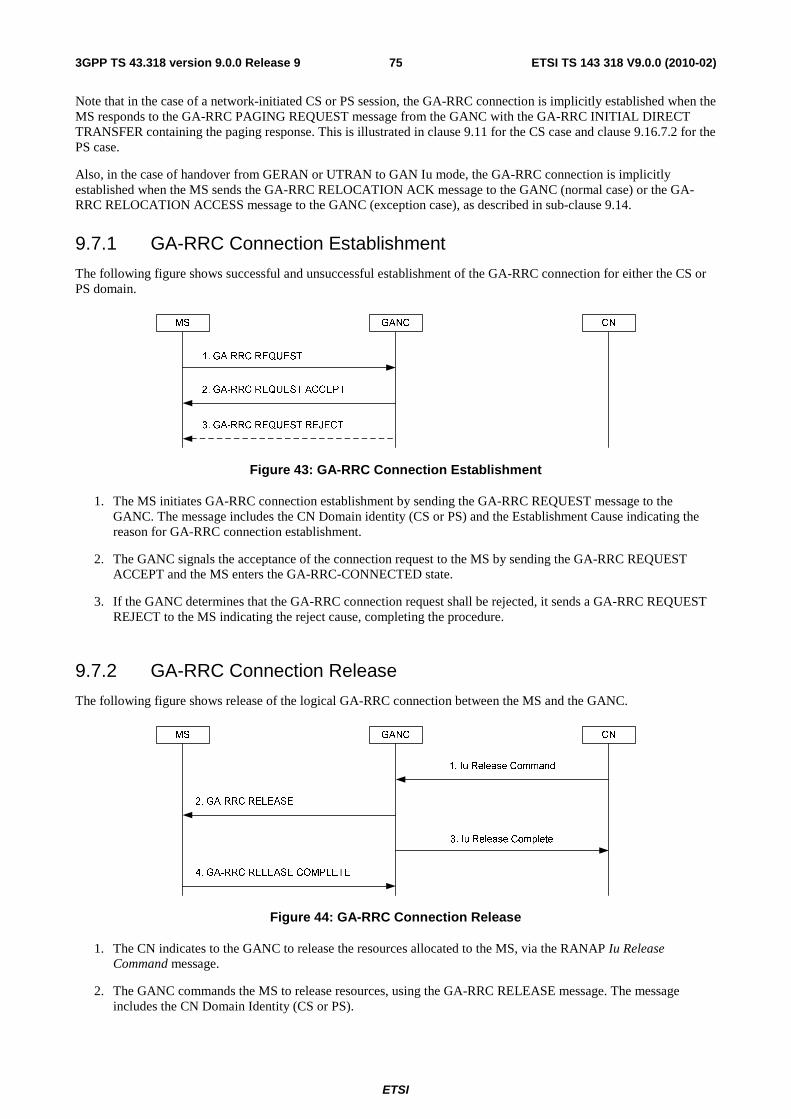
ETSI
ETSI TS 143 318 V9.0.0 (2010-02)753GPP TS 43.318 version 9.0.0 Release 9
Note that in the case of a network-initiated CS or PS session, the GA-RRC connection is implicitly established when the MS responds to the GA-RRC PAGING REQUEST message from the GANC with the GA-RRC INITIAL DIRECT TRANSFER containing the paging response. This is illustrated in clause 9.11 for the CS case and clause 9.16.7.2 for the PS case.
Also, in the case of handover from GERAN or UTRAN to GAN Iu mode, the GA-RRC connection is implicitly established when the MS sends the GA-RRC RELOCATION ACK message to the GANC (normal case) or the GA-RRC RELOCATION ACCESS message to the GANC (exception case), as described in sub-clause 9.14.
9.7.1 GA-RRC Connection Establishment
The following figure shows successful and unsuccessful establishment of the GA-RRC connection for either the CS or PS domain.
Figure 43: GA-RRC Connection Establishment
1. The MS initiates GA-RRC connection establishment by sending the GA-RRC REQUEST message to the GANC. The message includes the CN Domain identity (CS or PS) and the Establishment Cause indicating the reason for GA-RRC connection establishment.
2. The GANC signals the acceptance of the connection request to the MS by sending the GA-RRC REQUEST ACCEPT and the MS enters the GA-RRC-CONNECTED state.
3. If the GANC determines that the GA-RRC connection request shall be rejected, it sends a GA-RRC REQUEST REJECT to the MS indicating the reject cause, completing the procedure.
9.7.2 GA-RRC Connection Release
The following figure shows release of the logical GA-RRC connection between the MS and the GANC.
MS GANC
1. Iu Release Command
2. GA-RRC RELEASE
4. GA-RRC RELEASE COMPLETE
CN
3. Iu Release Complete
Figure 44: GA-RRC Connection Release
1. The CN indicates to the GANC to release the resources allocated to the MS, via the RANAP Iu Release Command message.
2. The GANC commands the MS to release resources, using the GA-RRC RELEASE message. The message includes the CN Domain Identity (CS or PS).
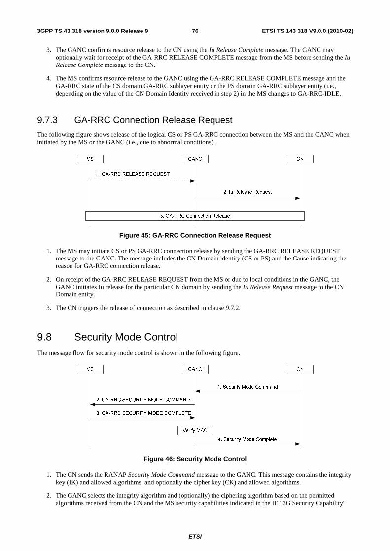
ETSI
ETSI TS 143 318 V9.0.0 (2010-02)763GPP TS 43.318 version 9.0.0 Release 9
3. The GANC confirms resource release to the CN using the Iu Release Complete message. The GANC may optionally wait for receipt of the GA-RRC RELEASE COMPLETE message from the MS before sending the Iu Release Complete message to the CN.
4. The MS confirms resource release to the GANC using the GA-RRC RELEASE COMPLETE message and the GA-RRC state of the CS domain GA-RRC sublayer entity or the PS domain GA-RRC sublayer entity (i.e., depending on the value of the CN Domain Identity received in step 2) in the MS changes to GA-RRC-IDLE.
9.7.3 GA-RRC Connection Release Request
The following figure shows release of the logical CS or PS GA-RRC connection between the MS and the GANC when initiated by the MS or the GANC (i.e., due to abnormal conditions).
Figure 45: GA-RRC Connection Release Request
1. The MS may initiate CS or PS GA-RRC connection release by sending the GA-RRC RELEASE REQUEST message to the GANC. The message includes the CN Domain identity (CS or PS) and the Cause indicating the reason for GA-RRC connection release.
2. On receipt of the GA-RRC RELEASE REQUEST from the MS or due to local conditions in the GANC, the GANC initiates Iu release for the particular CN domain by sending the Iu Release Request message to the CN Domain entity.
3. The CN triggers the release of connection as described in clause 9.7.2.
9.8 Security Mode Control The message flow for security mode control is shown in the following figure.
MS GANC
1. Security Mode Command
3. GA-RRC SECURITY MODE COMPLETE
CN
4. Security Mode Complete
Verify MAC
2. GA-RRC SECURITY MODE COMMAND
Figure 46: Security Mode Control
1. The CN sends the RANAP Security Mode Command message to the GANC. This message contains the integrity key (IK) and allowed algorithms, and optionally the cipher key (CK) and allowed algorithms.
2. The GANC selects the integrity algorithm and (optionally) the ciphering algorithm based on the permitted algorithms received from the CN and the MS security capabilities indicated in the IE "3G Security Capability"

ETSI
ETSI TS 143 318 V9.0.0 (2010-02)773GPP TS 43.318 version 9.0.0 Release 9
received from the MS in the GA-RC REGISTER REQUEST message. The GANC sends the GA-RRC SECURITY MODE COMMAND message to the MS. This message indicates the selected integrity protection algorithm and ciphering algorithm (i.e., that are applicable after handover to UTRAN), and a random number. The MS stores the information for possible future use after a handover to UTRAN.
3. The MS computes a MAC based on the random number, the MS IMSI and the integrity key. The MS then sends the GA-RRC SECURITY MODE COMPLETE message including the computed MAC.
4. The GANC verifies the MAC. If the GANC verifies the MAC to be correct it sends the Security Mode Complete message to the CN.
NOTE: The MAC proves that the identity that is authenticated to the GANC is the same as the identity authenticated to the core network.
9.9 NAS Signalling Procedures After GA-RRC connection establishment, NAS PDUs may be transferred from CN-to-MS and from MS-to-CN.
The initial NAS PDU from the MS to a core network domain is transferred in the GA-RRC INITIAL DIRECT TRANSFER message as illustrated in the following figure. This scenario assumes that a GA-RRC connection already exists between the MS and GANC; if not, the procedure described in clause 9.7.1 is performed before step 1.
Figure 47: Initial MS-to-CN NAS signalling
1. The MS receives a request from the NAS layer to establish a signalling connection to a core network domain. The request also includes a request to transfer an uplink NAS PDU. The MS encapsulates the NAS PDU within a GA-RRC INITIAL DIRECT TRANSFER message and sends the message to the GANC. The message includes the CN Domain identity (CS or PS). It also includes the Intra Domain NAS Node Selector (IDNNS) to be used by the GANC to route the establishment of a signalling connection to a CN node within the indicated CN domain (i.e., using IuFlex).
2. The GANC establishes a signalling connection to the indicated core network domain entity and relays the received NAS-PDU to the CN via the RANAP Initial UE Message message.
Subsequent NAS PDUs from the MS to the core network domain entity are transferred in the GA-RRC UPLINK DIRECT TRANSFER message as illustrated in the following figure.
Figure 48: MS-to-CN NAS signalling
1. The MS receives a request from the NAS layer to transfer an uplink NAS PDU. Assuming the required signalling connection already exists, the MS encapsulates the NAS PDU within a GA-RRC UL DIRECT TRANSFER message and sends the message to the GANC. The message includes the CN Domain identity (CS or PS).
2. The GANC relays the received NAS-PDU to the CN via the RANAP Direct Transfer message.

ETSI
ETSI TS 143 318 V9.0.0 (2010-02)783GPP TS 43.318 version 9.0.0 Release 9
NAS PDUs from the core network to the MS are transferred in the GA-RRC DOWNLINK DIRECT TRANSFER message as illustrated in the following figure.
Figure 49: CN-to-MS NAS signalling
1. For CN-to-MS NAS signalling, the CN sends a NAS PDU to the GANC via the RANAP Direct Transfer message.
2. The GANC encapsulates the NAS PDU within a GA-RRC DL DIRECT TRANSFER message and forwards the message to the MS via the existing TCP connection. The message includes the CN Domain identity (CS or PS).
9.10 Mobile Originated CS Call The description of the procedure in this sub-clause assumes the MS is in GAN Iu mode; i.e., it has successfully registered with the GANC and GA-RRC is the serving RR entity for CS services in the MS. It also assumes that no GA-RRC signalling connection for the CS domain exists between the MS and GANC; i.e., the CS domain GA-RRC sublayer entity in the MS is in the GA-RRC-IDLE state. If the CS domain GA-RRC sublayer entity in the MS is already in the GA-RRC-CONNECTED state, step 1 is skipped.

ETSI
ETSI TS 143 318 V9.0.0 (2010-02)793GPP TS 43.318 version 9.0.0 Release 9
MS GANC MSC
1. GA-RRC Connection Establishment
4. Authentication
5. Security Mode Control
6. GA-RRC UL DIRECT TRANSFER (Setup)
7. GA-RRC DL DIRECT TRANSFER (Call Proceeding)
8. RAB Assignment Request
10. GA-RRC ACTIVATE CHANNEL
11. GA-RRC ACTIVATE CHANNEL ACK
12. GA-RRC ACTIVATE CHANNEL COMPLETE
13. RAB Assignment Response
14. GA-RRC DL DIRECT TRANSFER (Alerting)
15. GA-RRC DL DIRECT TRANSFER (Connect)
16. GA-RRC UL DIRECT TRANSFER (Connect Ack)
17. Voice traffic
3. Initial UE Message (CM Service Request)
GA-RRC-
CONNECTED
2. GA-RRC INITIAL DIRECT TRANSFER (CM Service Request)
9. Iu Bearer Establishment and Iu UP Initialization
Figure 50: Mobile Originated CS Call
1. The CS GA-RRC Connection Establishment procedure is performed as described in clause 9.7.1.
2. The MS sends the CM Service Request message to the GANC within the GA-RRC INITIAL DIRECT TRANSFER message. The message includes the CN Domain identity (CS).
3. The GANC establishes an SCCP connection to the MSC and forwards the NAS PDU (i.e., the CM Service Request message) to the MSC using the RANAP Initial UE Message. The message includes the Domain Indicator set to value "CS domain". Subsequent NAS messages between the MS and MSC will be sent between GANC and MSC using the RANAP Direct Transfer message.
4. The MSC may optionally authenticate the MS using standard UTRAN authentication procedures.
5. The MSC normally initiates the Security Mode Control procedure described in clause 9.8.
6. The MS sends the Setup message providing details on the call to the MSC and its bearer capability and supported codecs. This message is contained within the GA-RRC UL DIRECT TRANSFER between the MS and the GANC. The GANC forwards the Setup message to the MSC.
7. The MSC indicates it has received the call setup and it will accept no additional call-establishment information using the Call Proceeding message to the GANC. The GANC forwards this message to the MS in the GA-RRC DL DIRECT TRANSFER message.
8. The MSC requests the GANC to assign call resources using the RANAP RAB Assignment Request message. The MSC includes the RAB ID, the CN Transport Layer Address and the CN Iu Transport Association for user data.

ETSI
ETSI TS 143 318 V9.0.0 (2010-02)803GPP TS 43.318 version 9.0.0 Release 9
9. The Iu bearer is established per standard Iu procedures. In the case of the ATM-based Iu-cs interface, this may include the exchange of ALCAP signalling between the GANC and the MSC to setup the ATM virtual circuit. For both ATM and IP-based Iu-cs interface types, Iu bearer establishment may also include the Iu UP initialization exchange, if Iu UP support mode is required as indicated by the MSC in the RANAP RAB Assignment Request message.
10. The GANC sends the GA-RRC ACTIVATE CHANNEL message to the MS including bearer path setup information such as:
- CN Domain ID (i.e., indicating CS domain).
- RAB ID (provided by the MSC in step 8).
- RAB Configuration (based on RAB parameters provided by the MSC in step 8).
- Multi-rate codec configuration.
- UDP port & the IP address for the uplink RTP stream.
- Voice sample size.
11. The MS sends the GA-RRC ACTIVATE CHANNEL ACK to the GANC indicating that the MS has successfully established a CS bearer channel for the call and including the UDP port for the downlink RTP stream.
12. The GANC signals the completion of the RAB establishment to the MS with the GA-RRC ACTIVATE CHANNEL COMPLETE message.
13. The GANC signals to the MSC that the RAB has been established by sending a RANAP RAB Assignment Response message.
14. The MSC signals to the MS, with the Alerting message, that the B-Party is ringing. The message is transferred to the GANC and GANC forwards the message to the MS in the GA-RRC DL DIRECT TRANSFER. If the MS has not connected the audio path to the user, it shall generate ring back to the calling party. Otherwise, the network-generated ring back will be returned to the calling party.
15. The MSC signals that the called party has answered, via the Connect message. The message is transferred to the GANC and GANC forwards the message to the MS in the GA-RRC DL DIRECT TRANSFER. The MS connects the user to the audio path. If the MS is generating ring back, it stops and connects the user to the audio path.
16. The MS sends the Connect Ack message in response, and the two parties are connected for the voice call. This message is contained within the GA-RRC UL DIRECT TRANSFER between the MS and the GANC. The GANC forwards the Connect Ack message to the MSC.
17. Bi-directional voice traffic flows between the MS and MSC through the GANC.
9.11 Mobile Terminated CS Call The description of the procedure in this clause assumes the MS is in GAN Iu mode; i.e., it has successfully registered with the GANC and GA-RRC is the serving RR entity for CS services in the MS.
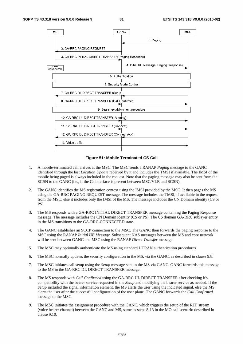
ETSI
ETSI TS 143 318 V9.0.0 (2010-02)813GPP TS 43.318 version 9.0.0 Release 9
Figure 51: Mobile Terminated CS Call
1. A mobile-terminated call arrives at the MSC. The MSC sends a RANAP Paging message to the GANC identified through the last Location Update received by it and includes the TMSI if available. The IMSI of the mobile being paged is always included in the request. Note that the paging message may also be sent from the SGSN to the GANC (i.e., if the Gs interface is present between MSC/VLR and SGSN).
2. The GANC identifies the MS registration context using the IMSI provided by the MSC. It then pages the MS using the GA-RRC PAGING REQUEST message. The message includes the TMSI, if available in the request from the MSC; else it includes only the IMSI of the MS. The message includes the CN Domain identity (CS or PS).
3. The MS responds with a GA-RRC INITIAL DIRECT TRANSFER message containing the Paging Response message. The message includes the CN Domain identity (CS or PS). The CS domain GA-RRC sublayer entity in the MS transitions to the GA-RRC-CONNECTED state.
4. The GANC establishes an SCCP connection to the MSC. The GANC then forwards the paging response to the MSC using the RANAP Initial UE Message. Subsequent NAS messages between the MS and core network will be sent between GANC and MSC using the RANAP Direct Transfer message.
5. The MSC may optionally authenticate the MS using standard UTRAN authentication procedures.
6. The MSC normally updates the security configuration in the MS, via the GANC, as described in clause 9.8.
7. The MSC initiates call setup using the Setup message sent to the MS via GANC. GANC forwards this message to the MS in the GA-RRC DL DIRECT TRANSFER message.
8. The MS responds with Call Confirmed using the GA-RRC UL DIRECT TRANSFER after checking it's compatibility with the bearer service requested in the Setup and modifying the bearer service as needed. If the Setup included the signal information element, the MS alerts the user using the indicated signal, else the MS alerts the user after the successful configuration of the user plane. The GANC forwards the Call Confirmed message to the MSC.
9. The MSC initiates the assignment procedure with the GANC, which triggers the setup of the RTP stream (voice bearer channel) between the GANC and MS, same as steps 8-13 in the MO call scenario described in clause 9.10.

ETSI
ETSI TS 143 318 V9.0.0 (2010-02)823GPP TS 43.318 version 9.0.0 Release 9
10. The MS signals that it is alerting the user, via the Alerting message contained in the GA-RRC UL DIRECT TRANSFER. The GANC forwards the Alerting message to the MSC. The MSC sends a corresponding alerting message to the calling party.
11. The MS signals that the called party has answered, via the Connect message contained in the GA-RRC UL DIRECT TRANSFER. The GANC forwards the Connect message to the MSC. The MSC sends a corresponding Connect message to the calling party and through connects the audio. The MS connects the user to the audio path.
12. The MSC acknowledges via the Connect Ack message to the GANC. GANC forwards this message to the MS in the GA-RRC DL DIRECT TRANSFER. The two parties on the call are connected on the audio path.
13. Bi-directional voice traffic flows between the MS and MSC through the GANC.
9.12 CS Call Clearing
9.12.1 CS Call Release
The following figure shows CS call clearing initiated by the MS. This scenario assumes that the MSC uses Iu Release to release the call (i.e., versus a separate RAB Release then Iu Release).
Figure 52: MS initiated CS Call release
1. The MS sends the Disconnect message to the CN to release the call. This message is contained in the GA-RRC UL DIRECT TRANSFER message between MS and GANC. The GANC forwards the Disconnect message to the CN (i.e., using the RANAP Direct Transfer message).
2. The CN responds with a Release message to the GANC. The GANC forwards this message to the MS using the GA-RRC DL DIRECT TRANSFER message.
3. The MS responds with the Release Complete message. This message is contained within the GA-RRC UL DIRECT TRANSFER message between MS and GANC. The GANC forwards the Disconnect message to the CN.
4. The CN triggers the release of connection as described in clause 9.7.2.
9.12.2 CS Channel Release
The following figure shows CS channel release (i.e., user plane only) corresponding to the Iu RAB Release procedure.

ETSI
ETSI TS 143 318 V9.0.0 (2010-02)833GPP TS 43.318 version 9.0.0 Release 9
MS GANC
1. RAB Assignment Request
2. GA-RRC DEACTIVATE CHANNEL
3. GA-RRC DEACTIVATE CHANNEL COMPLETE
MSC
4. RAB Assignment Response
Figure 53: CS channel release
1. The CN indicates to the GANC to release the RAB allocated to the MS (identified by the RAB ID), via the RANAP RAB Assignment Request message.
2. The GANC commands the MS to release the CS user plane channel (but maintain the CS signalling connection), using the GA-RRC DEACTIVATE CHANNEL message. The message includes the CN Domain ID (indicating CS) and the RAB ID.
3. The MS confirms CS channel release to the GANC using the GA-RRC DEACTIVATE CHANNEL COMPLETE message. The MS remains in the GA-RRC-CONNECTED state.
4. The GANC confirms resource release to CN using the RAB Assignment Response message.
9.13 CS Channel Modification The GANC may initiate the CS channel modification procedure when it determines that one or more active CS channels require modification; e.g., based on information received from the MSC in the RAB Assignment Request message or based on local GANC logic. For example, the GANC may initiate this procedure if it detects "packet loss" and handover to GERAN/UTRAN is not possible or desired. CS channel modification and PTC modification use the same messages and the same basic message flows, but differ in the content of the messages.
The GANC may modify the following parameters:
- RAB Configuration
- Sample Size
- RTP UDP Port
- GANC IP Address
- Multi-rate Configuration 2
- RTP Redundancy Configuration
- NAS Synchronisation Indicator
- RTCP UDP Port

ETSI
ETSI TS 143 318 V9.0.0 (2010-02)843GPP TS 43.318 version 9.0.0 Release 9
Figure 54: CS Channel Modification
1. A call is established as described in clauses 9.10 or 9.11.
2. The GANC sends the GA-RRC MODIFY CHANNEL message to the MS to modify parameters for the established call.
3. The MS responds with the GA-RRC MODIFY CHANNEL ACKNOWLEDGE message to the GANC.
9.14 CS Handover between GAN Iu mode and GERAN/UTRAN mode
9.14.1 CS Handover from GERAN to GAN
The description of the GERAN to GAN Handover procedure assumes the following:
• the MS is on an active call on the GERAN; and
• its mode selection is GAN-preferred, or if GERAN/UTRAN-preferred, the RxLev from the current serving cell drops below a defined threshold; and
• the MS has successfully registered with a GANC, allowing the MS to obtain GAN system information; and
• the GANC has directed the MS to operate in GAN Iu mode; and
• the GERAN provides information on neighbouring 3G cells such that one of the cells in the 3G neighbour list matches the 3G cell information associated with the GANC, as provided in the AS-related component of the system information obtained from the GANC.

ETSI
ETSI TS 143 318 V9.0.0 (2010-02)853GPP TS 43.318 version 9.0.0 Release 9
9.14.1.1 Normal case: IMSI is present in Relocation Request message
Figure 55: CS Handover from GERAN to GAN (IMSI in Relocation Request)
1. The MS has successfully registered with the GANC and begins to include GAN Iu mode cell information in the Measurement Report message to the GERAN. The MS reports the highest signal level for the GAN Iu mode cell. This is not the actual measured signal level on GAN, rather an artificial value (i.e., RxLev = 63), allowing the MS to indicate preference for the GAN.
2. Based on MS measurement reports and other internal algorithms, the GERAN BSC decides to handover to the GAN Iu mode cell. The BSC starts the handover preparation by sending a Handover Required message to the MSC, identifying the target 3G RNC (GANC).
3. The MSC requests the target GANC to allocate resources for the handover using the Relocation Request message. The MS is identified by the included IMSI parameter.
4. The Iu bearer is established per standard Iu procedures. In the case of the ATM-based Iu-cs interface, this may include the exchange of ALCAP signalling between the GANC and the MSC to setup the ATM virtual circuit. For both ATM and IP-based Iu-cs interface types, Iu bearer establishment may also include the Iu UP initialization exchange, if Iu UP support mode is required as indicated by the MSC in the RANAP Relocation Request message.
5. The GANC sends the GA-RRC RELOCATION REQUEST message to the MS including bearer path setup information such as:
- RAB ID (received from MSC in step 3)
- Multi-rate codec configuration.
- UDP port & the IP address for the uplink RTP stream.

ETSI
ETSI TS 143 318 V9.0.0 (2010-02)863GPP TS 43.318 version 9.0.0 Release 9
- Voice sample size.
6. The MS sends the GA-RRC RELOCATION REQUEST ACK to the GANC indicating that the MS has successfully established resources for the call and including the UDP port for the downlink RTP stream.
7. The GANC builds a Handover to UTRAN Command message and sends it to the MSC through the Relocation Request Acknowledge message.
8. The MSC forwards the Handover to UTRAN Command message to the GERAN BSC in the BSSMAP Handover Command message, completing the handover preparation.
9. The GERAN BSC sends the Intersystem to UTRAN Handover Command message, containing the Handover to UTRAN Command message, to the MS to initiate handover to GAN Iu mode. The MS does not switch its audio path from GERAN to GAN until handover completion (i.e., until it sends the GA-RRC RELOCATION COMPLETE message) to keep the audio interruption short.
10. The MS transmits the GA-RRC RELOCATION COMPLETE message to indicate the completion of the handover procedure. It switches the user from the GERAN user plane to the GAN Iu mode user plane.
11. The GANC indicates to the MSC that it has detected the MS, using Relocation Detect message. The MSC can optionally now switch the user plane from the source GERAN to the target GAN.
12. Bi-directional voice traffic is now flowing between the MS and CN, via GANC.
13. The GANC indicates the handover is complete, using the Relocation Complete message. If it had not done so before, the MSC now switches the user plane from source GERAN to target GAN.
14. Finally, the MSC tears down the connection to the source GERAN, using Clear Command message.
15. The source GERAN confirms the release of GERAN resources allocated for this call, using Clear Complete message.

ETSI
ETSI TS 143 318 V9.0.0 (2010-02)873GPP TS 43.318 version 9.0.0 Release 9
9.14.1.2 Exception Case: No IMSI in Relocation Request
MS GANC MSC
2. Handover Required
1. Um: Measurement Report
3. Relocation Request
12. GA-RRC RELOCATION COMPLETE
BSC
5. Relocation Request Acknowledge (Handover To UTRAN Command)
7. Um: Intersystem to UTRAN Handover Command (Handover to UTRAN Command)
6. Handover Command (Handover To UTRAN Command)
13. Relocation Detect
15. Relocation Complete
14. Voice traffic
16. Clear Command
17. Clear Complete
4. Iu Bearer Establishment and Iu UP Initialization
8. GA-RRC RELOCATION ACCESS
9. GA-RRC ACTIVATE CHANNEL
10. GA-RRC ACTIVATE CHANNEL ACK
11. GA-RRC ACTIVATE CHANNEL COMPLETE
GA-RC-
REGISTERED
GA-RRC-
CONNECTED
Figure 55a: CS Handover from GERAN to GAN (No IMSI in Relocation Request)
1-2. Same as steps 1-2 in clause 9.14.1.1.
3. The MSC requests the target GANC to allocate resources for the handover using the Relocation Request message. The IMSI parameter is not included in the message since it is not available at the MSC.
4. Same as step 4 in clause 9.14.1.1.
5-7. Same as steps 8-10 in clause 9.14.1.1.
8. The MS accesses the GANC using the GA-RRC RELOCATION ACCESS message, and provides the entire Intersystem to UTRAN Handover Command message received from GERAN. Information in the Intersystem to UTRAN Handover Command message (e.g. Handover Reference) allows the GANC to correlate the handover to the Relocation Request Acknowledge message sent to the MSC in step 5.
9-11. The GANC sets up the bearer path with the MS, using the procedure as in steps 10 to 12 in clause 9.10.
12. The MS transmits the GA-RRC RELOCATION COMPLETE message to indicate the completion of the handover procedure. It switches the user from the GERAN user plane to the GAN Iu mode user plane.

ETSI
ETSI TS 143 318 V9.0.0 (2010-02)883GPP TS 43.318 version 9.0.0 Release 9
13. The GANC indicates to the MSC that it has detected the MS, using the Relocation Detect message. The MSC can optionally now switch the user plane from the source GERAN to the target GAN.
14. Bi-directional voice traffic is now flowing between the MS and MSC, via the GANC.
15. The target GANC indicates the handover is complete, using the Relocation Complete message. If it had not done so before, the MSC now switches the user plane from source GERAN to target GAN.
16. Finally, the MSC tears down the connection to the source GERAN, using Clear Command message.
17. The source GERAN confirms the release of GERAN resources allocated for this call, using Clear Complete message.
9.14.2 CS Handover from UTRAN to GAN
The description of the UTRAN to GAN CS handover procedure assumes the following:
• the MS is on an active call on the UTRAN; and
• the MS has successfully registered with a GANC, allowing the MS to obtain GAN system information; and
• the GANC has directed the MS to operate in GAN Iu mode; and
• the UTRAN provides information on neighbouring cells such that one of the cells in the neighbour list matches the cell associated with the GANC, as provided in the AS-related component of the system information obtained from GANC.

ETSI
ETSI TS 143 318 V9.0.0 (2010-02)893GPP TS 43.318 version 9.0.0 Release 9
9.14.2.1 Normal Case: IMSI is present in Relocation Request message
Figure 56: CS Handover from UTRAN to GAN (IMSI in Relocation Request)
1. The MS begins to include information about a GAN Iu mode cell in the Measurement Report message sent to the RNC. See Annex B.2.1 for further information.
2. Based on MS measurement reports and other internal algorithms, the RNC decides to initiate handover to the GAN Iu mode cell. The RNC starts the preparation phase of the Relocation procedure by sending a Relocation Required message to the MSC, identifying the target (GAN Iu mode) cell.
3-6. Same as steps 3-6 for CS handover from GERAN to GAN in clause 9.14.1.1.
7. The GANC acknowledges the relocation request message, using Relocation Request Acknowledge message, indicating it can support the requested handover, and including a Physical Channel Reconfiguration message that indicates the radio channel to which the MS should be directed.
8. The MSC sends the Relocation Command message to the RNC, completing the relocation preparation.
9. The RNC sends the PHYSICAL CHANNEL RECONFIGURATION message to the MS to initiate handover to GAN Iu mode. The MS does not switch its audio path from UTRAN to GAN until handover completion (i.e., until it sends the GA-RRC HANDOVER COMPLETE message) to keep the audio interruption short.
10-13. Same as steps 10-13 for CS handover from GERAN to GAN in clause 9.14.1.1.
14. Finally, the MSC tears down the connection to the source RNC, using Iu Release Command.
15. The source RNC confirms the release of UTRAN resources allocated for this call, using Iu Release Complete.

ETSI
ETSI TS 143 318 V9.0.0 (2010-02)903GPP TS 43.318 version 9.0.0 Release 9
9.14.2.2 Exception Case: No IMSI in Relocation Request
MS GANC MSC
2. Relocation Required
1. Uu: Measurement Report
3. Relocation Request
RNC
5. Relocation Request Acknowledge (Physical Channel Reconfiguration)
7. Uu: Physical Channel Reconfiguration
6. Relocation Command (Physical Channel Reconfiguration)
13. Relocation Detect
15. Relocation Complete
14. Voice traffic
16. Iu Release Command
17. Iu Release Complete
4. Iu Bearer Establishment and Iu UP Initialization
8. GA-RRC RELOCATION ACCESS
12. GA-RRC RELOCATION COMPLETE
9. GA-RRC ACTIVATE CHANNEL
10. GA-RRC ACTIVATE CHANNEL ACK
11. GA-RRC ACTIVATE CHANNEL COMPLETE
GA-RC-
REGISTERED
GA-RRC-
CONNECTED
Figure 56a: CS Handover from UTRAN to GAN (No IMSI in Relocation Request)
1-2. Same as steps 1-2 in clause 9.14.2.1.
3. The MSC requests the target GANC to allocate resources for the handover using the Relocation Request message. The IMSI parameter is not included in the message since it is not available at the MSC.
4. Same as step 4 in clause 9.14.2.1.
5-7. Same as steps 7-9 in clause 9.14.2.1.
8. The MS accesses the GANC using the GA-RRC RELOCATION ACCESS message, and provides the entire Physical Channel Reconfiguration message received from UTRAN. Information in the Physical Channel Reconfiguration message allows the GANC to correlate the handover to the Relocation Request Acknowledge message sent to the MSC in step 5.
9-11. The GANC sets up the bearer path with the MS, using the procedure as in steps 10 to 12 in sub-clause 9.10.
12. The MS transmits the GA-RRC RELOCATION COMPLETE message to indicate the completion of the handover procedure at its end. It switches the user from the UTRAN user plane to the GAN user plane.
ETSI
ETSI TS 143 318 V9.0.0 (2010-02)913GPP TS 43.318 version 9.0.0 Release 9
13. The GANC indicates to the MSC that it has detected the MS, using the Relocation Detect message. The MSC can optionally now switch the user plane from the source UTRAN to the target GAN.
14. Bi-directional voice traffic is now flowing between the MS and MSC, via the GANC.
15. The target GANC indicates the handover is complete, using the Relocation Complete message. If it had not done so before, the MSC now switches the user plane from source UTRAN to target GAN.
16. Finally, the MSC tears down the connection to the source RNC, using Iu Release Command.
17. The source RNC confirms the release of UTRAN resources allocated for this call, using Iu Release Complete.
9.14.3 CS Handover from GAN Iu mode to GERAN
The procedure description in this sub-clause assumes the following:
• the MS is on an active call in GAN Iu mode; and
• the GERAN becomes available; and
• the MS mode selection is GERAN/UTRAN-preferred; or
• the MS mode selection is GAN-preferred and the MS begins to leave GAN coverage, based on its local measurements, received RTCP reports, as well as any uplink quality indications received from the GANC.
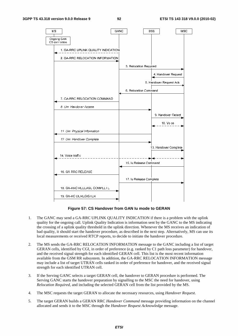
ETSI
ETSI TS 143 318 V9.0.0 (2010-02)923GPP TS 43.318 version 9.0.0 Release 9
MS GANC MSC
Ongoing GAN
CS connection
3. Relocation Required
BSS
8. Um: Handover Access
2. GA-RRC RELOCATION INFORMATION
7. GA-RRC RELOCATION COMMAND
6. Relocation Command
14. Voice traffic
15. Iu Release Command
17. Iu Release Complete
1. GA-RRC UPLINK QUALITY INDICATION
4. Handover Request
5. Handover Request Ack
9. Handover Detect
12. Um: Handover Complete
13. Handover Complete
10. Voice
11. Um: Physical Information
18. GA-RRC RELEASE COMPLETE
16. GA-RRC RELEASE
19. GA-RC DEREGISTER
Figure 57: CS Handover from GAN Iu mode to GERAN
1. The GANC may send a GA-RRC UPLINK QUALITY INDICATION if there is a problem with the uplink quality for the ongoing call. Uplink Quality Indication is information sent by the GANC to the MS indicating the crossing of a uplink quality threshold in the uplink direction. Whenever the MS receives an indication of bad quality, it should start the handover procedure, as described in the next step. Alternatively, MS can use its local measurements or received RTCP reports, to decide to initiate the handover procedure.
2. The MS sends the GA-RRC RELOCATION INFORMATION message to the GANC including a list of target GERAN cells, identified by CGI, in order of preference (e.g. ranked by C1 path loss parameter) for handover, and the received signal strength for each identified GERAN cell. This list is the most recent information available from the GSM RR subsystem. In addition, the GA-RRC RELOCATION INFORMATION message may include a list of target UTRAN cells ranked in order of preference for handover, and the received signal strength for each identified UTRAN cell.
3. If the Serving GANC selects a target GERAN cell, the handover to GERAN procedure is performed. The Serving GANC starts the handover preparation by signalling to the MSC the need for handover, using Relocation Required, and including the selected GERAN cell from the list provided by the MS.
4. The MSC requests the target GERAN to allocate the necessary resources, using Handover Request.
5. The target GERAN builds a GERAN RRC Handover Command message providing information on the channel allocated and sends it to the MSC through the Handover Request Acknowledge message.

ETSI
ETSI TS 143 318 V9.0.0 (2010-02)933GPP TS 43.318 version 9.0.0 Release 9
6. The MSC signals the GANC to handover the MS to the GERAN, using the Relocation Command message which includes the encapsulated GERAN RRC Handover Command message, ending the handover preparation phase.
7. GANC transmits the GA-RRC RELOCATION COMMAND to the MS including the UTRAN RRC Handover from UTRAN Command message, which encapsulates the GERAN RRC Handover Command message.
8. The MS transmits Handover Access containing the handover reference element to allow the target GERAN to correlate this handover access with the Handover Command message transmitted earlier to the MSC in response to the Handover Required.
9. The target GERAN confirms the detection of the handover to the MSC, using the Handover Detect message.
10. The MSC may at this point switch the user plane to the target BSS.
11. The GERAN provides Physical Information to the MS (i.e., Timing Advance) to allow the MS to synchronize with the GERAN.
12. The MS signals to the GERAN that the handover is completed, using Handover Complete.
13. The GERAN confirms to the MSC the completion of the handover, via Handover Complete message. The MSC may use the target CGI used in the Handover procedure for charging purposes.
14. Bi-directional voice traffic is now flowing between the MS and MSC, via the GERAN.
15. On receiving the confirmation of the completion of the handover, the MSC indicates to the GANC to release any resources allocated to the MS, via the Iu Release Command.
16. If the GANC has not already received the GA-RC DEREGISTER message from the MS, the GANC commands the MS to release resources, using the GA-RRC RELEASE message.
17. GANC confirms resource release to MSC using the Iu Release Complete message.
18. The MS confirms resource release to the GANC using the GA-RRC RELEASE COMPLETE message.
19. The MS may finally deregister from the GANC, using GA-RC DEREGISTER message. Note that the MS may send the GA-RC DEREGISTER message at any time after transitioning from GAN Iu mode to GERAN mode (i.e., after step 12).
9.14.4 CS Handover from GAN Iu mode to UTRAN
The procedure description in this sub-clause assumes the following:
• the MS is on an active call in GAN Iu mode; and
• the MS is capable of operating in all of the GAN, GERAN and UTRAN modes; and
• the UTRAN becomes available; and
• the MS is in GERAN/UTRAN-preferred mode; or
• the MS mode selection is GAN preferred and begins to leave GAN coverage, based on its local measurements, received RTCP reports, as well as any uplink quality indications received from the GANC.

ETSI
ETSI TS 143 318 V9.0.0 (2010-02)943GPP TS 43.318 version 9.0.0 Release 9
MS GANC CN
Ongoing GAN
CS connection
3. Relocation Required
RNS
8. Uu: UL Synchronization
2. GA-RRC RELOCATION INFORMATION
7. GA-RRC RELOCATION COMMAND
6. Relocation Command
13. Voice traffic
14. Iu Release Command
16. Iu Release Complete
1. GA-RRC UPLINK QUALITY INDICATION
4. Relocation Request
5. Relocation Request Ack
9. Relocation Detect
11. Uu: Physical Channel Reconfig Complete
12. Relocation Complete
10. Voice
17. GA-RRC RELEASE COMPLETE
15. GA-RRC RELEASE
18. GA-RC DEREGISTER
Figure 58: CS Handover from GAN Iu mode to UTRAN
1. The GANC may send a GA-RRC UPLINK QUALITY INDICATION if there is a problem with the uplink quality for the ongoing call. Uplink Quality Indication is information sent by the GANC to the MS indicating the crossing of a uplink quality threshold in the uplink direction. Whenever the MS receives an indication of bad quality, it should start the handover procedure, as described in the next step. Alternatively, MS can use its local measurements or received RTCP reports, to decide to initiate the handover procedure.
2. The MS sends the GA-RRC RELOCATION INFORMATION message to the Serving GANC including a list of candidate target UTRAN and GERAN cells, in order of preference for handover, and the received signal strength for each identified cell. The UTRAN cells are identified by the PLMN ID, the LAC and the 3G Cell identity (defined in 3GPP TS 25.331 [23]).
NOTE: The choice of the candidate target UTRAN cells is out of the scope of this technical specification.
3. If the Serving GANC selects UTRAN as the target RAT, the CS handover to UTRAN procedure is performed. The Serving GANC starts the handover preparation by signalling to the MSC the need for handover, using Relocation Required and including the target RNC-ID that the GANC derives from the target UTRAN cell it selects from the list of target UTRAN cells provided by the MS. The GANC may include only a single target RNC-ID in the Relocation Required message. The GANC also includes the Source RNC to Target RNC Transparent Container that contains the selected target UTRAN cell ID.
4. The MSC starts the relocation procedure towards the target RNC identified by the Serving GANC. The MSC requests from the target RNC to allocate the necessary resources using Relocation Request.

ETSI
ETSI TS 143 318 V9.0.0 (2010-02)953GPP TS 43.318 version 9.0.0 Release 9
5. The target RNC builds a Physical Channel Reconfiguration message providing information on the allocated UTRAN resources and sends it to the MSC through the Relocation Request Acknowledge message.
6. The MSC signals the Serving GANC to handover the MS to the UTRAN, using the Relocation Command message (which includes the Physical Channel Reconfiguration message), ending the handover preparation phase.
7. The Serving GANC transmits the GA-RRC RELOCATION COMMAND to the MS including the Physical Channel Reconfiguration message.
8. Target RNS achieves uplink synchronization on the Uu interface.
9. The target RNC confirms the detection of the handover to the MSC, using the Relocation Detect message.
10. The MSC may at this point switch the user plane to the target RNS.
11. The MS signals to the UTRAN that the handover is completed, using Physical Channel Reconfig Complete.
12. The UTRAN confirms to the MSC the completion of the handover, via Relocation Complete message. If the user plane has not been switched in step 10, the MSC switches the user plane to the target RNS.
13. Bi-directional voice traffic is now flowing between the MS and MSC, via the UTRAN.
14. On receiving the confirmation of the completion of the handover, the MSC indicates to the Serving GANC to release any resources allocated to the MS, via the Iu Release Command.
15. If the Serving GANC has not already received the GA-RC DEREGISTER message from the MS, the Serving GANC commands the MS to release resources, using the GA-RRC RELEASE message.
16. The Serving GANC confirms resource release to MSC using the Iu Release Complete message.
17. The MS confirms resource release to the Serving GANC using the GA-RRC RELEASE COMPLETE message.
18. The MS may finally deregister from the Serving GANC, using GA-RC DEREGISTER message. Note that the MS may send the GA-RC DEREGISTER message at any time after transitioning from GAN Iu mode to UTRAN mode (i.e., after step 11).
9.15 Cell Change Order between GAN Iu mode and GERAN mode
While in GERAN, a mobile station may be ordered to perform a cell reselection to GAN Iu mode, by using the Cell Change Order procedures used in GERAN, with no modifications. The mobile station regards the procedure as completed when it has successfully performed Rove In to GAN.
While the mobile station is involved in a PS session in the GAN Iu mode, there is no identified need for a Cell Change Order procedure.
9.16 GA-RRC Packet Transport Channel Management Procedures
The GA-RRC Packet Transport Channel (GA-RRC PTC) provides the association between the MS and the network for the transport of PS domain user data over the Up interface in GAN Iu mode.
The endpoint addresses of the PTC are identified by the IP addresses and UDP ports assigned to the PTC in the MS and GANC during the PTC activation procedure. The GA-RRC PTC is strictly limited to operating over the Up interface and as such all downlink GA-RRC messages sent by the GANC shall terminate at the MS and all uplink GA-RRC messages sent by the MS shall terminate at the GANC.
Multiple PTC instances between a MS and the GANC may be activated at the same time, using the same endpoint addresses. Each PTC instance is assigned unique GA-RRC Tunnel Endpoint IDs (one on the MS and one on the GANC) during the activation procedure.
ETSI
ETSI TS 143 318 V9.0.0 (2010-02)963GPP TS 43.318 version 9.0.0 Release 9
The MS and GANC manage the activation and deactivation of the PTC instances based on the requests for RAB assignment from the SGSN and the configurable PTC Timer.
9.16.1 States of the GA-RRC Packet Transport Channel
The PS domain GA-RRC sublayer entity in the MS when in the GA-RRC-CONNECTED state can be in one of two PTC substates for each PTC: PTC-INACTIVE or PTC-ACTIVE.
• PTC-INACTIVE: This is the initial/default PTC substate of the PS domain GA-RRC sublayer entity in the MS when in the GA-RRC-CONNECTED state in GAN Iu mode. The MS is not able to send or receive PS domain user data to or from the network using the PTC. The PTC must be activated before domain user data can be transferred via the PTC. When the PTC has been successfully activated between the MS and the GANC, the PS domain GA-RRC sublayer entity in the MS transitions to the PTC-ACTIVE substate for this PTC.
• PTC-ACTIVE: The PS domain GA-RRC sublayer entity in the MS is in the GA-RRC-CONNECTED state for this PTC and the PTC is active between the MS and the GANC and the MS is able to send and receive PS domain user data to and from the GANC.
The following are the possible triggers for GA-RRC PTC activation:
• The GANC initiates PTC activation when the GANC receives the RAB Assignment message from the SGSN; i.e., the MS receives a GA-RRC ACTIVATE CHANNEL message from the GANC;
• The GANC initiates PTC activation when the GANC receives the Relocation Request message from the SGSN; i.e., the MS receives a GA-RRC RELOCATION REQUEST message from the GANC including PTC information.
On successful PTC activation and in parallel with transition to the PTC-ACTIVE substate, the MS starts the PTC Timer for this PTC. When the PTC Timer expires, the MS sends a message to the GANC to initiate PTC deactivation, as defined in clause 9.16.4. On successful PTC deactivation, the MS transitions to the PTC-INACTIVE substate for this PTC.
At any time while the PS domain GA-RRC sublayer entity in the MS is in the GA-RRC-CONNECTED state and the PTC-ACTIVE substate, the MS may receive the GA-RRC DEACTIVATE CHANNEL message for this PTC. The MS de-activates the PTC and transitions to the PTC-INACTIVE substate.
At any time while the PS domain GA-RRC sublayer entity in the MS is in the GA-RRC-CONNECTED state and the PTC-ACTIVE substate, the MS may receive the GA-RRC RELEASE message indicating the PS domain. In addition to requesting release of the PS GA-RRC connection, this is interpreted by the MS as an implicit PTC de-activation command; i.e. all active PTCs are deactivated.
At any time while in GAN Iu mode, if the serving RR entity is switched to GSM-RR/UTRAN-RRC, the PS domain GA-RRC sublayer entity in the MS is disconnected from the GPRS SAPs and the MS enters GERAN/UTRAN mode. Simultaneously, the MS shall de-activate the associated PTC(s) regardless of the PTC Timer status for these PTC(s).
The PS domain GA-RRC sublayer entity in the MS maintains one PTC for each active PDP context. The PTC Timer is restarted whenever any uplink user data packet is sent or downlink user data packet is received related to the PDP context.
The PTC Timer value is provided to the MS as part of the GAN Registration procedure (i.e., in the GA-RC REGISTER ACCEPT message).
9.16.2 PTC Activation
9.16.2.1 PTC Activation when GANC receives RAB Assignment Request
The following figure depicts the Packet Transport Channel activation procedure when the GANC receives the RAB Assignment Request message from the SGSN, assuming the PS domain GA-RRC sublayer entity in MS is in the GA-RRC-IDLE state. If the PS domain GA-RRC sublayer entity in MS is already in the GA-RRC-CONNECTED state, step 1 is skipped.

ETSI
ETSI TS 143 318 V9.0.0 (2010-02)973GPP TS 43.318 version 9.0.0 Release 9
Figure 59: PTC activation based on RAB Assignment Request
1. The GA-RRC Connection Establishment procedure is performed as described in clause 9.7. The PS domain GA-RRC sublayer entity in the MS transitions to the GA-RRC-CONNECTED state and the PTC-INACTIVE substate.
2. Additional PS signalling procedures are performed; e.g., to initiate PDP context activation.
3. The SGSN initiates the RAB Assignment procedure and includes the RAB ID, the CN Transport Layer Address (IP address) and the CN Iu Transport Association (GTP-U Tunnel Endpoint Identifier, TEID) for user data. Note that the SGSN may initiate the activation of multiple RABs via a single RAB Assignment Request message; in this case, the SGSN sends the above parameters for each RAB to the GANC.
4. The GANC sends the GA-RRC ACTIVATE CHANNEL message to the MS to request activation of the Packet Transport Channel(s). The message includes the CN Domain ID, RAB ID, a TEID that the GANC assigns to the MS for downlink data transfer, the GANC PTC IP Address (i.e., the destination address for PTC GA-RRC PDU messages from the MS) and the GANC TEID assigned by the GANC for uplink data transfer, for each of the RABs.
5. The MS acknowledges the activation of the PTC(s).
6. The GANC signals the completion of the RAB establishment to the MS with the GA-RRC ACTIVATE CHANNEL COMPLETE message. On receipt of the message, the PS domain GA-RRC sublayer entity in the MS transitions to the PTC-ACTIVE substate for each PTC and starts the PTC Timer for each PTC.
7. The GANC sends the RAB Assignment Response message to the SGSN to complete the RAB Assignment procedure. The GANC includes the RAB ID, the RAN Transport Layer Address (i.e., the GANC"s Iu-PS IP address) and the RAN Iu Transport Association (i.e., the TEID that the GANC assigned to the MS).
8. Additional PS signalling procedures are performed; e.g., to complete the PDP context activation.
9. The MS transfers uplink user data by sending a GA-RRC PDU message to the GANC PTC IP address received in step 4. The message includes the GANC TEID received in step 4, which allows the GANC to relay the GA-

ETSI
ETSI TS 143 318 V9.0.0 (2010-02)983GPP TS 43.318 version 9.0.0 Release 9
RRC PDU message payload using the correct GTP-U tunnel on the Iu-PS interface. The GANC relays the message payload to the SGSN in the Iu-PS G-PDU message.
10. The SGSN transfers downlink user data by sending a Iu-PS G-PDU message to the GANC Iu-PS IP address received in step 7. The message includes the MS TEID received in step 7, which allows the GANC to relay the Iu-PS G-PDU message payload using the correct PTC on the Up interface. The GANC relays the message payload to the MS in the GA-RRC PDU message.
9.16.2.2 PTC Activation when GANC receives Relocation Request
The following figure depicts the Packet Transport Channel activation procedure when the GANC receives the Relocation Request message from the SGSN.
Figure 59a: PTC activation based on Relocation Request
1. The MS has successfully registered with the GANC. The MS, GANC and SGSN perform signalling procedures related to PS handover, as described in sub-clause 9.23.
2. The SGSN sends the Relocation Request message to the GANC and includes the RAB ID, the CN Transport Layer Address (IP address) and the CN Iu Transport Association (GTP-U Tunnel Endpoint Identifier, TEID) for user data. Note that the SGSN may request the relocation of multiple RABs via a single Relocation Request message; in this case, the SGSN sends the above parameters for each RAB to the GANC.
3. The GANC sends the GA-RRC RELOCATION REQUEST message to the MS to request activation of the Packet Transport Channel(s) for PS handover purposes. The message includes the RAB ID, a TEID that the GANC assigns to the MS for downlink data transfer, the GANC PTC IP Address (i.e., the destination address for PTC GA-RRC PDU messages from the MS) and the GANC TEID assigned by the GANC for uplink data transfer, for each of the RABs.
4. The MS acknowledges the activation of the PTC(s) in the GA-RRC RELOCATION REQUEST ACK message. The PS domain GA-RRC sublayer entity in the MS transitions to the GA-RRC-CONNECTED state and the PTC-ACTIVE substate for each PTC and starts the PTC Timer for each PTC.
5. The GANC sends the Relocation Request Ack message to the SGSN to complete the handover preparation procedure. The GANC includes the RAB ID, the RAN Transport Layer Address (i.e., the GANC"s Iu-PS IP address) and the RAN Iu Transport Association (i.e., the TEID that the GANC assigned to the MS) for each RAB.
6. PS handover is performed, as described in sub-clause 9.23.
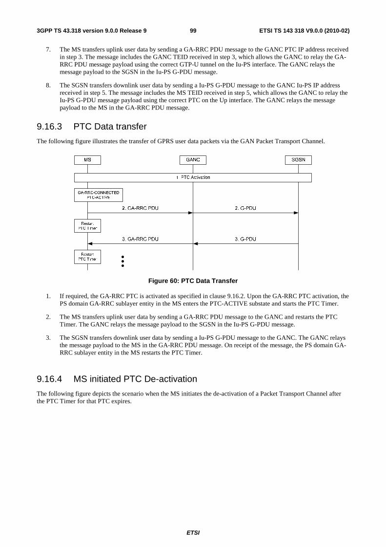
ETSI
ETSI TS 143 318 V9.0.0 (2010-02)993GPP TS 43.318 version 9.0.0 Release 9
7. The MS transfers uplink user data by sending a GA-RRC PDU message to the GANC PTC IP address received in step 3. The message includes the GANC TEID received in step 3, which allows the GANC to relay the GA-RRC PDU message payload using the correct GTP-U tunnel on the Iu-PS interface. The GANC relays the message payload to the SGSN in the Iu-PS G-PDU message.
8. The SGSN transfers downlink user data by sending a Iu-PS G-PDU message to the GANC Iu-PS IP address received in step 5. The message includes the MS TEID received in step 5, which allows the GANC to relay the Iu-PS G-PDU message payload using the correct PTC on the Up interface. The GANC relays the message payload to the MS in the GA-RRC PDU message.
9.16.3 PTC Data transfer
The following figure illustrates the transfer of GPRS user data packets via the GAN Packet Transport Channel.
Figure 60: PTC Data Transfer
1. If required, the GA-RRC PTC is activated as specified in clause 9.16.2. Upon the GA-RRC PTC activation, the PS domain GA-RRC sublayer entity in the MS enters the PTC-ACTIVE substate and starts the PTC Timer.
2. The MS transfers uplink user data by sending a GA-RRC PDU message to the GANC and restarts the PTC Timer. The GANC relays the message payload to the SGSN in the Iu-PS G-PDU message.
3. The SGSN transfers downlink user data by sending a Iu-PS G-PDU message to the GANC. The GANC relays the message payload to the MS in the GA-RRC PDU message. On receipt of the message, the PS domain GA-RRC sublayer entity in the MS restarts the PTC Timer.
9.16.4 MS initiated PTC De-activation
The following figure depicts the scenario when the MS initiates the de-activation of a Packet Transport Channel after the PTC Timer for that PTC expires.

ETSI
ETSI TS 143 318 V9.0.0 (2010-02)1003GPP TS 43.318 version 9.0.0 Release 9
MS GANC SGSN
1. PTC Timer expires
4. RAB Assignment Request
2. GA-RRC DEACTIVATE CHANNEL REQUEST
5. GA-RRC DEACTIVATE CHANNEL
7. RAB Assignment Response
GA-RRC-CONNECTED
PTC-ACTIVE
GA-RRC-CONNECTED
PTC-INACTIVE
3. RAB Release Request
6. GA-RRC DEACTIVATE CHANNEL COMPLETE
Figure 61: MS initiated PTC de-activation
The PS domain GA-RRC sublayer entity in the MS is in the GA-RRC-CONNECTED state and the PTC-ACTIVE substate.
1. The PTC Timer associated with one of the active PTCs expires.
2. The MS sends the GA-RRC DEACTIVATE CHANNEL REQUEST message to the GANC, including the CN Domain ID, the RAB ID to identify the PTC and indicating the normal release as a cause for deactivation.
3. The GANC sends a RAB Release Request message to the SGSN to request the release of the associated RAB. Note that the GANC may also initiate Iu Release in this case, based on local policy settings.
4. The SGSN responds with the RAB Assignment Request indicating release.
5. The GANC sends the GA-RRC DEACTIVATE CHANNEL message to the MS, including the CN Domain ID and the RAB ID.
6. The MS de-activates the PTC, sends the GA-RRC DEACTIVATE CHANNEL COMPLETE message to the GANC and the PS domain GA-RRC sublayer entity in the MS transitions to the PTC-INACTIVE substate for this PTC.
7. The GANC sends the RAB Assignment Response message to notify the SGSN that the RAB Release procedure is complete.
9.16.5 MS initiated PTC Re-activation
The following figure depicts the scenario when the MS initiates re-activation of the Packet Transport Channel while the PS domain GA-RRC sublayer entity in the MS is in the GA-RRC-CONNECTED and the MS is in the PMM-CONNECTED state; e.g., a PS signalling connection and active PDP context exists between the MS and CN but the PTC was previously de-activated by the MS due to PTC Timer expiry.

ETSI
ETSI TS 143 318 V9.0.0 (2010-02)1013GPP TS 43.318 version 9.0.0 Release 9
MS GANC SGSN
GA-RRC-CONNECTED
PTC-INACTIVE
GA-RRC-CONNECTED
PTC-ACTIVE
2. Direct Transfer (Service Request=Data)
1. GA-RRC UL DIRECT TRANSFER (Service Request=Data)
4. RAB Direct Transfer (Service Accept)
5. GA-RRC DL DIRECT TRANSFER (Service Accept)
3. Security Mode Control
6. Packet Transport Channel (PTC) activation
7. GA-RRC PDU 7. G-PDU
Figure 62: MS initiated PTC re-activation
The PS domain GA-RRC sublayer entity in the MS is in the GA-RRC-CONNECTED state and the PTC-INACTIVE substate. The MS is in the PMM-CONNECTED state (i.e., a PS signalling connection and an active PDP context exists).
1. The MS has a PDU to send. The MS sends the Service Request message (with Service type value 'Data') to the GANC in the GA-RRC UL DIRECT TRANSFER message.
2. The GANC forwards the Service Request over the existing signalling connection to the SGSN using the RANAP Direct Transfer message.
3. The SGSN normally initiates the Security Mode Control procedure described in clause 9.8.
4. The SGSN responds with a Service Accept message.
5. The GANC forwards the message to the MS.
6. The MS, GANC and SGSN perform the RAB assignment and the PTC activation as described in steps 3-7 in clause 9.16.2.1.
7. The MS transfers the uplink user data by sending a GA-RRC PDU message to the GANC and starts the PTC Timer. The GANC relays the message to the SGSN in the Iu-PS G-PDU message. Additional data transfer may take place.
9.16.6 Network initiated PTC De-activation
The following figure depicts the scenario when the network initiates de-activation of one or more Packet Transport Channel(s).
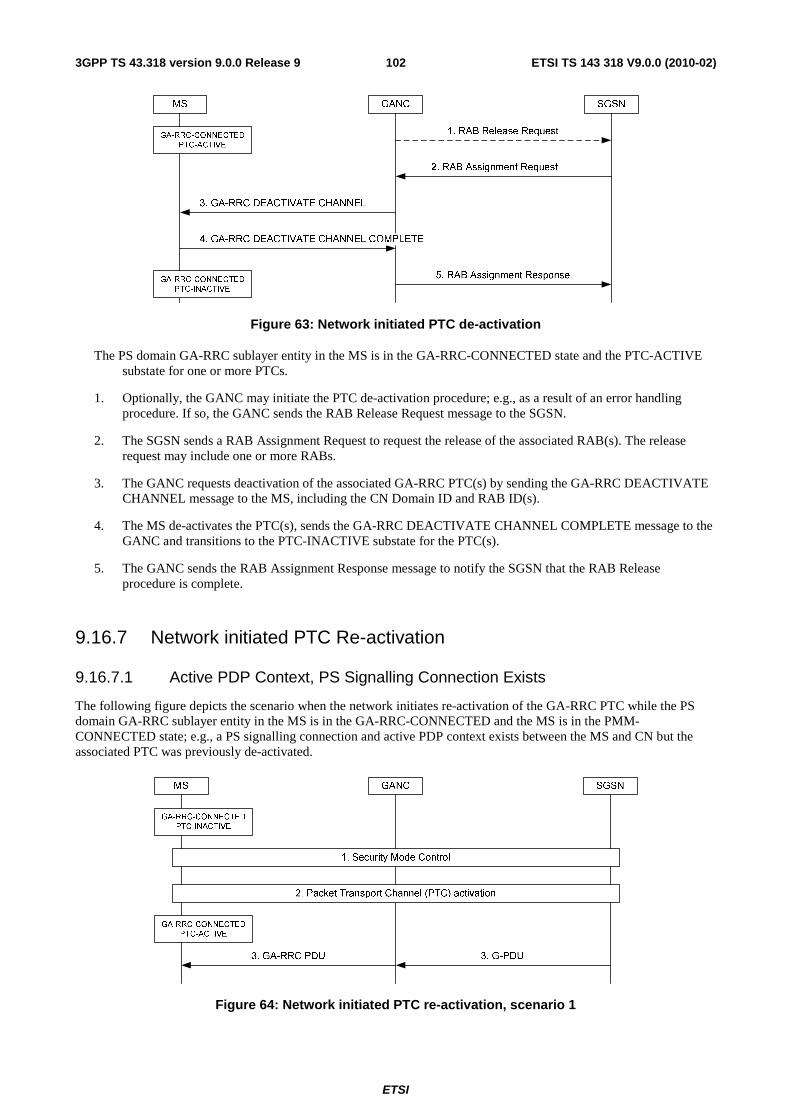
ETSI
ETSI TS 143 318 V9.0.0 (2010-02)1023GPP TS 43.318 version 9.0.0 Release 9
Figure 63: Network initiated PTC de-activation
The PS domain GA-RRC sublayer entity in the MS is in the GA-RRC-CONNECTED state and the PTC-ACTIVE substate for one or more PTCs.
1. Optionally, the GANC may initiate the PTC de-activation procedure; e.g., as a result of an error handling procedure. If so, the GANC sends the RAB Release Request message to the SGSN.
2. The SGSN sends a RAB Assignment Request to request the release of the associated RAB(s). The release request may include one or more RABs.
3. The GANC requests deactivation of the associated GA-RRC PTC(s) by sending the GA-RRC DEACTIVATE CHANNEL message to the MS, including the CN Domain ID and RAB ID(s).
4. The MS de-activates the PTC(s), sends the GA-RRC DEACTIVATE CHANNEL COMPLETE message to the GANC and transitions to the PTC-INACTIVE substate for the PTC(s).
5. The GANC sends the RAB Assignment Response message to notify the SGSN that the RAB Release procedure is complete.
9.16.7 Network initiated PTC Re-activation
9.16.7.1 Active PDP Context, PS Signalling Connection Exists
The following figure depicts the scenario when the network initiates re-activation of the GA-RRC PTC while the PS domain GA-RRC sublayer entity in the MS is in the GA-RRC-CONNECTED and the MS is in the PMM-CONNECTED state; e.g., a PS signalling connection and active PDP context exists between the MS and CN but the associated PTC was previously de-activated.
Figure 64: Network initiated PTC re-activation, scenario 1

ETSI
ETSI TS 143 318 V9.0.0 (2010-02)1033GPP TS 43.318 version 9.0.0 Release 9
The PS domain GA-RRC sublayer entity in the MS is in the GA-RRC-CONNECTED state and the PTC-INACTIVE substate. The MS is in the PMM-CONNECTED state (i.e., a PS signalling connection and an active PDP context exists).
1. The SGSN has a PDU to send to the MS. The SGSN may optionally initiate the Security Mode Control procedure described in clause 9.8.
2. The MS, GANC and SGSN perform the RAB assignment and PTC activation as described in steps 3-7 in clause 9.16.2.1.
3. The SGSN sends the downlink PDU. Additional data transfer may take place.
9.16.7.2 Active PDP Context, No PS Signalling Connection
The following figure depicts the scenario when the network initiates re-activation of the Packet Transport Channel while the MS is in the PMM-CONNECTED state; e.g., no PS signalling connection exists but an active PDP context exists between the MS and CN.
Figure 65: Network initiated PTC re-activation, scenario 2
Initially, the SGSN receives downlink user data to transfer to the MS and the Iu connection is not established. The MS is in the PMM-CONNECTED state.
1. The SGSN sends the RANAP Paging message to the MS via the GANC to locate the user. The paging request indicates paging for PS Domain signalling.
2. The GANC forwards the paging information to the MS in the GA-RRC PAGING REQUEST message.
3. The MS responds with a GA-RRC INITIAL DIRECT TRANSFER message. The PS domain GA-RRC sublayer entity in the MS transitions to the GA-RRC-CONNECTED state.
4. The GANC establishes an SCCP connection to the SGSN and forwards the Service Request message (with Service type value 'Paging response') to the SGSN using the RANAP Initial UE Message. Subsequent NAS messages between the MS and core network will be sent between GANC and SGSN using the RANAP Direct Transfer message.
5. The SGSN may optionally authenticate the MS using standard UTRAN authentication procedures.
6. The SGSN normally initiates the Security Mode Control procedure described in clause 9.8.
7. The MS, GANC and SGSN perform the RAB assignment and the GA-RRC PTC activation as described in steps 3-7 in clause 9.16.2.1.

ETSI
ETSI TS 143 318 V9.0.0 (2010-02)1043GPP TS 43.318 version 9.0.0 Release 9
8. The MS and SGSN exchange user data transfer via the established PTC as defined in clause 9.16.3.
9.16.8 Implicit PTC De-activation due to MS De-registration
As part of the GAN de-registration procedure, the GANC needs to release all resources allocated to the MS. GAN de-registration may be initiated either explicitly by the MS or implicitly by the GANC if the loss of the signalling connection is detected (as described in clause 9.4.2).
Figure 66: Implicit PTC deactivation
Initially, the PS domain GA-RRC sublayer entity in the MS is in the PTC-ACTIVE substate for one or more GA-RRC PTCs associated with the MS.
1. The GAN de-registration procedure is initiated for the MS either by the MS or GANC.
2. Optionally, any outstanding resources associated with the CS Domain are released.
3. Optionally, if there are any outstanding resources associated with the PS Domain, the GANC initiates the Iu release procedure to the SGSN to release the corresponding RABs.
4. The SGSN reponds with Iu Release Command.
5. Upon receiving the Iu Release Command, the GANC implicitly de-activates (i.e., locally) all associated PTCs and…
6. …responds to the SGSN with an Iu Release Complete message.
9.16.9 PTC Modification
The GANC may initiate the packet transport channel (PTC) modification procedure when it determines that one or more active PTCs require modification; e.g., based on information received from the SGSN in the RAB Assignment Request message or based on local GANC logic. For example, the GANC may initiate this procedure if it detects "packet loss" and handover to GERAN/UTRAN is not possible or desired. CS channel modification and PTC modification use the same messages and the same basic message flows, but differ in the content of the messages.
The GANC may modify the following PTC parameters:
- RAB Configuration
- GANC TEID
- MS TEID

ETSI
ETSI TS 143 318 V9.0.0 (2010-02)1053GPP TS 43.318 version 9.0.0 Release 9
- GANC UDP Port
- GANC IP Address
Figure 66a: PTC Modification
1. One or more PTC(s) are activated as described in sub-clause 9.16.2.
2. The GANC sends the GA-RRC MODIFY CHANNEL message to the MS to modify parameters for one or more of the activated PTCs.
3. The MS responds with the GA-RRC MODIFY CHANNEL ACKNOWLEDGE message to the GANC.
9.17 (void)
9.18 (void)
9.19 Short Message Service GAN provides support for SMS via the CS domain and the PS domain. GAN-attached and GPRS enabled mobile stations will be able to send and receive SMS messages via the CS domain or the PS domain, regardless of the GPRS class (B or C) with the restriction that the class C mobiles can support only SMS via the PS domain.
9.19.1 SMS via the CS domain
Support for SMS via the CS domain in GAN is based on the same mechanism that is utilized for GSM mobility management and call control. On the MS side, the SMS layers (including the supporting CM sub layer functions) utilize the services of the MM layer to transfer SMS messages per standard circuit switched GSM implementation. The SM-CP protocol is effectively tunnelled between the MS and the CN, using GA-RRC messages from the MS to the GANC, where the GANC relays the SM-CP to RANAP messages for transport over the Iu-cs interface.
As with GSM mobility management and call control procedures, the secure IPsec tunnel and TCP session are used to provide secure and reliable SMS delivery over the IP network.
9.19.2 SMS via the PS domain
Support for SMS via the PS domain is based on the same mechanism as the transfer of the GPRS MM/SM signalling messages. The SM-CP protocol is effectively tunnelled between the MS and the CN, using GA-RRC messages from the MS to the GANC, where the GANC relays the SM-CP to RANAP messages for transport over the Iu-ps interface.
As with GPRS signalling, the secure IPsec tunnel and TCP session is used to provide secure and reliable GPRS SMS delivery over the IP network.

ETSI
ETSI TS 143 318 V9.0.0 (2010-02)1063GPP TS 43.318 version 9.0.0 Release 9
9.20 Supplementary Services UMTS has a large number of standardized supplementary services. These supplementary services involve procedures that operate end-to-end between the MS and the MSC. The CM messages used for the supplementary service are relayed between the MS and MSC in the same manner as in the other call control and mobility management scenarios described in this document.
9.21 Emergency Services See clause 8.21.
9.22 Location Services See clause 8.22.
9.23 PS Handover between GAN Iu mode and GERAN/UTRAN mode
9.23.1 PS Handover from GERAN to GAN
9.23.1.1 Preparation Phase
The description of the GERAN to GAN PS handover procedure assumes the following:
• the MS has one or more active packet flow contexts in the GERAN;
• the MS has successfully registered with a GANC, allowing the MS to obtain GAN system information;
• the GANC has directed the MS to operate in GAN Iu mode;
• the PS handover is intra-SGSN (i.e., assumes that the SGSN is capable of both 2G and 3G operation and interworking); and
• the GERAN provides information on neighbouring cells such that one of the cells in the neighbour list matches the cell associated with the GANC, as provided in the AS-related component of the system information obtained from the GANC.
MSTarget
GANC
2G/3G
SGSN
Source
BSS
2. PS Handover Required
3. Relocation Request
5. Relocation Request Ack
1. Decision to perform PS handover
GAN
Registered
4. GA-RRC PTC Activation
Figure 67: GERAN to GAN PS Handover Preparation Phase

ETSI
ETSI TS 143 318 V9.0.0 (2010-02)1073GPP TS 43.318 version 9.0.0 Release 9
1. The source BSS decides to initiate a PS handover. At this point both uplink and downlink user data is transmitted via the following: TBFs between MS and source BSS, BSSGP PFCs tunnel(s) between the source BSS and 3G/2G SGSN, GTP tunnel(s) between the 3G/2G SGSN and GGSN.
2. The source BSS sends a PS Handover Required message (TLLI, Cause, Source Cell Identifier, Target RNC Identifier, Source RNC to Target RNC Transparent Container, Active PFCs List) to the SGSN.
3. The SGSN determines from the Target RNC Identifier that this is a GERAN to UTRAN handover. The SGSN constructs a Relocation Request message as described in 3GPP TS 43.129 [44] and sends the message to the target GANC.
4. One or more GAN PTCs are activated between the MS and the GANC as specified in steps 3-4 in sub-clause 9.16.2.2. Upon each GA-RRC PTC activation, the PS domain GA-RRC sublayer entity in the MS enters the PTC-ACTIVE substate and starts the PTC Timer for the PTC.
5. The GANC sends the Relocation Request Acknowledge message (Target RNC to Source RNC Transparent Container, RABs setup list, RABs failed to setup list) to the SGSN. Upon sending the Relocation Request Acknowledge message the target GANC shall be prepared to receive downlink GTP PDUs from the SGSN for the accepted RABs.
When the SGSN receives the Relocation Request Acknowledge message and it decides to proceed with the handover, the preparation phase is finished and the execution phase will follow.
9.23.1.2 Execution Phase
Figure 68: GERAN to GAN PS Handover Execution Phase
1. The SGSN continues to receive IP packets from the GGSN (via GTP) and forwards the associated PDU payload to the MS via the source BSS.
2. When receiving the Relocation Request Acknowledge message the SGSN may, based on QoS, start downlink N-PDU relay and duplication to the target GANC if a Tunnel Endpoint is available as follows:
• For PDP context, which uses LLC ADM, all new downlink N-PDUs received after completion of the PS handover preparation phase are relayed to the target GANC. All such N-PDUs are encapsulated in a GTP-PDU when transmitted to the target GANC.

ETSI
ETSI TS 143 318 V9.0.0 (2010-02)1083GPP TS 43.318 version 9.0.0 Release 9
• If the 3G/2G SGSN forwards downlink packets to the target GANC, the target GANC may start blind transmission of downlink user data towards the MS over the allocated PTC(s).
3. The SGSN continues the PS Handover by sending a PS Handover Required Acknowledge message (TLLI, List of Set Up PFCs, Target RNC to Source RNC Transparent Container) to the source BSS, as described in 3GPP TS 43.129 [44].
4. The SGSN shall send the Forward SRNS Context message (NSAPI, DL GTP-U number, UL GTP-U number) to the target GANC if there is at least one PDP context which requires "delivery order" to be preserved, as described in 3GPP TS 43.129 [44].
The target GANC proceed as follows:
• For RABs not requiring lossless PDCP the target GANC may, according the QoS profile of the PDP context, store the received data until it receives confirmation of MS presence in the target cell.
• The target GANC disregards PDCP sequence numbers, since lossless relocation is not supported.
5. The source BSS sends the PS Handover Command message containing the Handover to UTRAN Command message (as it is specified in 3GPP TS 25.331 [40]) to the MS, as described in 3GPP TS 43.129 [44].
6. Immediately after receiving the PS Handover Command message, the MS sends GA-RRC RELOCATION COMPLETE message to the GANC.
7. Immediately upon receiving the GA-RRC RELOCATION COMPLETE message from the MS, the GANC sends the Relocation Detect message to the SGSN.
8. The GANC sends the Relocation Complete message to the SGSN, indicating the completion of the PS handover. After the reception of the Relocation Complete message the SGSN shall be prepared to receive data from the target GANC.
9. If the SGSN has established Direct Tunnel, the SGSN sends an Update PDP Context Request message (RNC Address, TEID, QoS Negotiated, DTI) to the GGSN concerned. The SGSN provides to the GGSN the GANC address for the User Plane and TEID for downlink data and shall include the DTI to instruct the GGSN to apply Direct Tunnel specific error handling procedure as defined in 3GPP TS 23.060 [19]. The GGSN updates the PDP context fields and returns an Update PDP Context Response message (TEID). From now on the GGSN sends new incoming downlink IP packets to the target GANC instead of the SGSN.
10. The SGSN shall initiate PFC Management procedures towards the source GERAN cell in order to trigger the release of resources in the source cell.
11. The MS and SGSN perform the Routing Area Update procedure as described in 3GPP TS 43.129 [44].
9.23.2 PS Handover from UTRAN to GAN
9.23.2.1 Preparation Phase
The description of the UTRAN to GAN PS handover procedure assumes the following:
• the Iur interface between the UTRAN RNC and GANC is not supported. Therefore, only the Combined Hard Handover and SRNS Relocation is applicable for GAN – UTRAN PS handover. Consequently, only the 'MS Involved' Relocation Type is supported;
• the MS has one or more active PDP Contexts with active RABs in the UTRAN;
• the MS has successfully registered with a GANC, allowing the MS to obtain GAN system information;
• the GANC has directed the MS to operate in GAN Iu mode; and
• the UTRAN provides information on neighbouring cells such that one of the cells in the neighbour list matches the cell associated with the GANC, as provided in the AS-related component of the system information obtained from the GANC. See Annex B.2.1 for more information.

ETSI
ETSI TS 143 318 V9.0.0 (2010-02)1093GPP TS 43.318 version 9.0.0 Release 9
MSTarget
GANCSGSN
Source
RNC
GAN
Registered
2. Relocation Required
3. Relocation Request
5. Relocation Request Ack
4. GA-RRC PTC Activation
1. Decision to perform Hard Handover & SRNS Relocation
Figure 69: UTRAN to GAN PS Handover Preparation Phase
1. Based on measurement results and knowledge of the RAN topology, the source SRNC decides to initiate a combined hard handover and SRNS relocation.
2. The source SRNC sends a Relocation Required message (Relocation Type, Cause, Source ID, Target ID, Source RNC To Target RNC Transparent Container) to the SGSN.
3. The SGSN determines the target cell is the GANC, based on the contents of Relocation Required. It then sends the Relocation Request message (Permanent NAS UE Identity, Cause, CN Domain Indicator, Source RNC To Target RNC Transparent Container, RAB To Be Setup) to the GANC.
If the IMSI is not present in the Permanent NAS UE Identity IE in the Relocation Request message, the GANC shall send the Relocation Failure message to the SGSN including Cause value 'Relocation Failure In Target CN/RNC Or Target System' and abort the relocation procedure.
4. One or more GAN PTCs are established between the GANC and MS as specified in steps 3-4 in sub-clause 9.16.2.2. Upon the GA-RRC PTC establishment, the PS domain GA-RRC sublayer entity in the MS enters the PTC-ACTIVE substate and starts the PTC Timer for the PTC.
5. The GANC sends the Relocation Request Acknowledge message (Target RNC To Source RNC Transparent Container, RABs Setup, RABs Failed To Setup) to the SGSN.

ETSI
ETSI TS 143 318 V9.0.0 (2010-02)1103GPP TS 43.318 version 9.0.0 Release 9
9.23.2.2 Execution Phase
Figure 70: UTRAN to GAN PS Handover Execution Phase
1. Upon receiving the positive acknowledgement from the GANC to serve the MS, the SGSN initiates the Execution Phase by sending the Relocation Command to the source SRNC.
2. a) The RNC may start forwarding GTP PDUs to the GANC while still transmitting them in the downlink to the MS. This forwarding is routed via the Iu-PS interface. The GANC may buffer, start a blind transmission of downlink user data towards the MS over the allocated PTC(s), or discard these forwarded GTP PDUs, depending on the QoS profile, network conditions, and whether it supports data forwarding.
b) The RNC instructs the MS to initiate the switch to GAN via the Physical Channel Reconfiguration message.
c) The RNC sends the Forward SRNS Context message to the GANC via the SGSN. In this message, the next-expected sequence number of uplink and downlink GTP-U packets are indicated to the GANC by the RNC.
3. Immediately after receiving the Physical Channel Reconfiguration message, the MS sends GA-RRC RELOCATION COMPLETE message to the GANC. Upon receiving this message and the Forward SRNS Context message, the GANC becomes the Serving RNC.
4. Immediately upon receiving the GA-RRC HANDOVER COMPLETE message from the MS, the GANC sends the Relocation Detect message to the SGSN.
5. The GANC sends the Relocation Complete message to the SGSN.
6. The MS, GANC and CN exchange user data via the established PTC.
7. The SGSN releases the Iu-PS connection with the old RNC.
8. If the Routing Area of the GANC cell (as indicated by the GANC to the MS in GAN registration) is different from that under the old RNC, then the MS performs the Routing Area Update procedure.
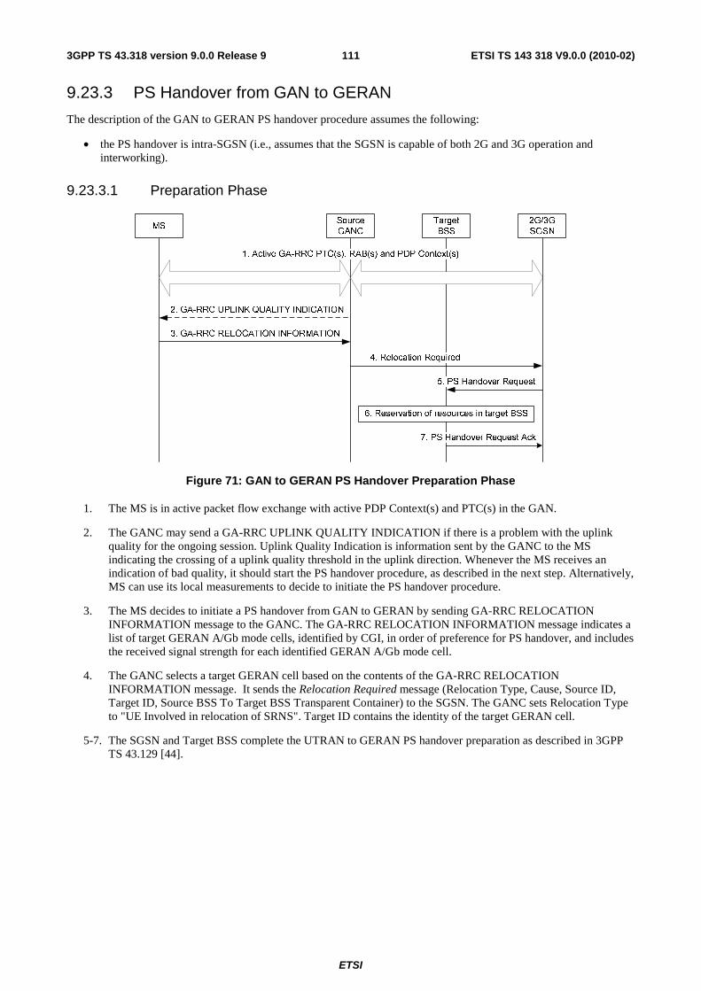
ETSI
ETSI TS 143 318 V9.0.0 (2010-02)1113GPP TS 43.318 version 9.0.0 Release 9
9.23.3 PS Handover from GAN to GERAN
The description of the GAN to GERAN PS handover procedure assumes the following:
• the PS handover is intra-SGSN (i.e., assumes that the SGSN is capable of both 2G and 3G operation and interworking).
9.23.3.1 Preparation Phase
Figure 71: GAN to GERAN PS Handover Preparation Phase
1. The MS is in active packet flow exchange with active PDP Context(s) and PTC(s) in the GAN.
2. The GANC may send a GA-RRC UPLINK QUALITY INDICATION if there is a problem with the uplink quality for the ongoing session. Uplink Quality Indication is information sent by the GANC to the MS indicating the crossing of a uplink quality threshold in the uplink direction. Whenever the MS receives an indication of bad quality, it should start the PS handover procedure, as described in the next step. Alternatively, MS can use its local measurements to decide to initiate the PS handover procedure.
3. The MS decides to initiate a PS handover from GAN to GERAN by sending GA-RRC RELOCATION INFORMATION message to the GANC. The GA-RRC RELOCATION INFORMATION message indicates a list of target GERAN A/Gb mode cells, identified by CGI, in order of preference for PS handover, and includes the received signal strength for each identified GERAN A/Gb mode cell.
4. The GANC selects a target GERAN cell based on the contents of the GA-RRC RELOCATION INFORMATION message. It sends the Relocation Required message (Relocation Type, Cause, Source ID, Target ID, Source BSS To Target BSS Transparent Container) to the SGSN. The GANC sets Relocation Type to "UE Involved in relocation of SRNS". Target ID contains the identity of the target GERAN cell.
5-7. The SGSN and Target BSS complete the UTRAN to GERAN PS handover preparation as described in 3GPP TS 43.129 [44].

ETSI
ETSI TS 143 318 V9.0.0 (2010-02)1123GPP TS 43.318 version 9.0.0 Release 9
9.23.3.2 Execution Phase
MSTarget
BSS
2G/3G
SGSN
Source
GANC
1. Relocation Command
GGSN
2. GA-RRC Relocation Command
6. Routing Area Update Procedure
3. GERAN A/Gb access procedures
5. Iu Release Command
5. Iu Release Complete
2. Forwarding of data
2. Forward SRNS Context
4. Completion of GERAN PS handover procedures
Figure 72: GAN to GERAN PS Handover Execution Phase
1. The SGSN begins the Execution Phase by issuing a Relocation Command message (Target BSS to Source BSS Transparent Container (PS Handover Command with RN part and CN part), RABs to be Released List, RABs Subject to Data Forwarding List) to the GANC.
2. a) The GANC may begin data forwarding for the RABs subject to data forwarding according to the procedure defined in 3GPP TS 43.129 [44].
b) The GANC sends GA-RRC RELOCATION COMMAND to the MS. This message contains the information from the Relocation Command received in step 1.
c) The GANC sends the Forward SRNS Context message to the SGSN.
3. The MS executes the GERAN A/Gb PS handover access procedures as described in 3GPP TS 43.129 [44].
4. After successfully accessing the GERAN cell, the MS, target BSS, SGSN and GGSN complete the GERAN PS handover procedures as described in 3GPP TS 43.129 [44].
5. The SGSN releases the Iu-PS connection by sending the Iu Release Command message to the GANC, to which GANC responds with the Iu Release Complete message.
6. If the Routing Area of the UTRAN cell is different from that of the GAN cell, then the MS performs the Routing Area Update procedure.

ETSI
ETSI TS 143 318 V9.0.0 (2010-02)1133GPP TS 43.318 version 9.0.0 Release 9
9.23.4 PS handover from GAN to UTRAN
9.23.4.1 Preparation Phase
MSSource
GANCSGSN
4. Relocation Required
Target
RNC
3. GA-RRC RELOCATION INFORMATION
2. GA-RRC UPLINK QUALITY INDICATION
5. Relocation Request
7. Relocation Request Ack
6. RAN, Iu Resource Allocation
1. Active GA-RRC PTC(s), RAB(s) and PDP Context(s)
Figure 73: GAN to UTRAN PS Handover Preparation Phase
1. The MS is in active packet flow exchange with active PDP Context(s) and PTC(s) in the GAN.
2. The GANC may send a GA-RRC UPLINK QUALITY INDICATION if there is a problem with the uplink quality for the ongoing session. Uplink Quality Indication is information sent by the GANC to the MS indicating the crossing of a uplink quality threshold in the uplink direction. Whenever the MS receives an indication of bad quality, it should start the relocation procedure, as described in the next step. Alternatively, MS can use its local measurements to decide to initiate the handover procedure.
3. The MS decides to initiate a PS handover from GAN to UTRAN by sending GA-RRC RELOCATION INFORMATION message to the GANC.
4. The GANC selects a target RNC based on the contents of the GA-RRC RELOCATION INFORMATION message. It sends Relocation Required message to the SGSN containing the selected RNC information.
5. The SGSN sends a Relocation Request message to the target RNC.
6. The RNC performs the necessary allocation of radio and Iu transport resources.
7. The RNC returns Relocation Request Acknowledge message to the SGSN. This message contains a transparent container that contains channelization information needed by MS to access UTRAN.
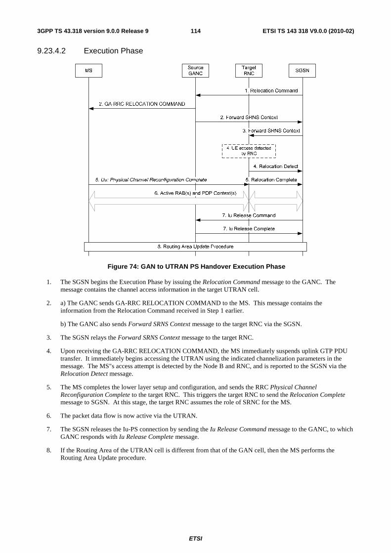
ETSI
ETSI TS 143 318 V9.0.0 (2010-02)1143GPP TS 43.318 version 9.0.0 Release 9
9.23.4.2 Execution Phase
Figure 74: GAN to UTRAN PS Handover Execution Phase
1. The SGSN begins the Execution Phase by issuing the Relocation Command message to the GANC. The message contains the channel access information in the target UTRAN cell.
2. a) The GANC sends GA-RRC RELOCATION COMMAND to the MS. This message contains the information from the Relocation Command received in Step 1 earlier.
b) The GANC also sends Forward SRNS Context message to the target RNC via the SGSN.
3. The SGSN relays the Forward SRNS Context message to the target RNC.
4. Upon receiving the GA-RRC RELOCATION COMMAND, the MS immediately suspends uplink GTP PDU transfer. It immediately begins accessing the UTRAN using the indicated channelization parameters in the message. The MS"s access attempt is detected by the Node B and RNC, and is reported to the SGSN via the Relocation Detect message.
5. The MS completes the lower layer setup and configuration, and sends the RRC Physical Channel Reconfiguration Complete to the target RNC. This triggers the target RNC to send the Relocation Complete message to SGSN. At this stage, the target RNC assumes the role of SRNC for the MS.
6. The packet data flow is now active via the UTRAN.
7. The SGSN releases the Iu-PS connection by sending the Iu Release Command message to the GANC, to which GANC responds with Iu Release Complete message.
8. If the Routing Area of the UTRAN cell is different from that of the GAN cell, then the MS performs the Routing Area Update procedure.

ETSI
ETSI TS 143 318 V9.0.0 (2010-02)1153GPP TS 43.318 version 9.0.0 Release 9
Annex A (normative): Security mechanisms
A.1 EAP based Authentication
A.1.1 EAP-SIM Procedure for authentication
HSS/HLR AAA MS Generic IP
Access Network GANC- SEGW
4. EAP Response/Identity [NAI based on IMSI]
5. EAP Request/SIM Start 6. EAP Request/SIM Start
7. EAP Response/SIM Start [NONCE_MT]
8. EAP Response/SIM Start [NONCE_MT]
9. Send Auth Info
10. Response (triplets) 11. EAP Request/SIM-Challenge [RAND, MAC, Next re-auth ID]
12. EAP Request/SIM-Challenge [RAND, MAC, Next re-auth ID]
14. EAP SIM/Response-Challenge [MAC]
15. EAP SIM/Response-Challenge [MAC]
17. EAP Success + keying material 18. EAP Success
19. Complete IKE signalling
2a. IKE_SA_INIT
2b. IKE_SA_INIT
2c. IKE_AUTH (NAI in IDi, no AUTH included)
1. Generic IP Access network connection establishment
3. Select appropriate AAA server
13. Execute EAP/SIM
16. Verify MAC
20. GAN Registration
Figure A.1: EAP-SIM authentication procedure

ETSI
ETSI TS 143 318 V9.0.0 (2010-02)1163GPP TS 43.318 version 9.0.0 Release 9
The EAP-SIM authentication mechanism is specified in [30]. This clause describes how this mechanism is used in GAN.
1. The MS connects to the generic IP access network.
2. The MS obtains the IP address of the GANC-SEGW, and initializes the IKEv2 authentication procedure by starting the IKE_SA_INIT exchange. It indicates the desire to use EAP by leaving out the AUTH payload from message 3 of the IKE_AUTH exchange, and the initiator identity is composed compliant with the Network Access Identifier (NAI) format specified in RFC 2486 [36], which contains the IMSI.
3. The GANC-SEGW communicates with the local AAA server through the Wm interface, which in turn determines the proper AAA Server based on the realm part of the NAI. The routing path may include one or several AAA proxies (not shown in figure A.1).
4. The GANC-SEGW sends an EAP Response/Identity message to the AAA server, containing the identity included in the third IKE message. This triggers the start of EAP-SIM.
5. The AAA Server identifies the subscriber as a candidate for authentication with EAP-SIM, based on the received identity, and sends the EAP Request/SIM-Start packet to GANC-SEGW.
6. The GANC-SEGW forwards the EAP Request/SIM-Start packet to MS.
7. The MS chooses a fresh random number NONCE_MT. The random number is used in network authentication. The MS sends the EAP Response/SIM-Start packet, containing NONCE_MT, to the GANC-SEGW.
8. The GANC-SEGW forwards the EAP Response/SIM-Start packet to the AAA Server.
9. The AAA server requests authentication data from the HLR, based on the IMSI. Note that the AAA server could instead use cached triplets previously retrieved from the HLR to continue the authentication process.
10. The AAA server receives multiple triplets from the HLR.
11. The AAA server formulates an EAP-SIM/Challenge with multiple RAND challenges, and includes a message authentication code (MAC) whose master key is computed based on the associated Kc keys, as well as the NONCE_MT. A new re-authentication identity may be chosen and protected (i.e. encrypted and integrity protected) using EAP-SIM generated keying material. The AAA Server sends this RAND, MAC and re-authentication identity to the GANC-SEGW in the EAP Request/SIM-Challenge message.
12. The GANC-SEGW forwards the EAP Request/SIM-Challenge message to the MS.
13. The MS runs N times the GSM A3/A8 algorithm in the SIM, once for each received RAND. This computing gives N SRES and Kc values. The MS calculates its copy of the network authentication MAC with the newly derived keying material and checks that it is equal with the received MAC. If the MAC is incorrect, the network authentication has failed and the MS cancels the authentication. The MS continues the authentication exchange only if the MAC is correct. The MS calculates a new MAC with the new keying material covering the EAP message concatenated to the N SRES responses. If a re-authentication ID was received, then the MS stores this ID for future authentications.
14. The MS sends EAP Response/SIM-Challenge containing calculated MAC to the GANC-SEGW.
15. The GANC-SEGW forwards the EAP Response/SIM-Challenge packet to the AAA Server.
16. The AAA Server verifies that its copy of the response MAC is equal to the received MAC.
17. If the comparison in step 16 is successful, then the AAA Server sends the EAP Success message to the GANC-SEGW. The AAA Server includes derived keying material for confidentiality and/or integrity protection between MS and GANC-SEGW, in the underlying AAA protocol message (i.e. not at EAP level).
18. The GANC-SEGW informs the MS about the successful authentication with the EAP Success message.
19. Now the EAP-SIM exchange has been successfully completed, the IKE signalling can be completed
20. The Secure Association between MS and GANC-SEGW has been completed and the MS can continue with the discovery or registration procedure.

ETSI
ETSI TS 143 318 V9.0.0 (2010-02)1173GPP TS 43.318 version 9.0.0 Release 9
A.1.2 EAP-AKA Procedure for authentication The EAP-AKA authentication mechanism is specified in [EAP AKA]. This section describes how this mechanism is used in GAN.
AAA MS
Generic IP Access Network
GANC- SEGW
1. Generic IP Access network connection establishment
2a. IKE_SA_INIT
4. EAP Response/Identity [NAI based on IMSI]
7. EAP Request/AKA Challenge[RAND, AUTN, MAC, Next re-auth ID]
8. EAP Request/AKA Challenge[RAND, AUTN, MAC, Next re-auth ID]
10. EAP Response/ AKA Challenge[RES, MAC]
11. EAP Response/ AKA Challenge[RES, MAC]
5. Send Auth Info
6. Response (Authentication vector)
13. EAP Success + keying material 14. EAP Success
15. Complete IKE signalling
2b. IKE_SA_INIT 2c. IKE_AUTH (NAI in IDi, no AUTH included)
HSS/HLR
3. Select appropriate AAA server
9. Run UMTS algorithms and verify AUTN
12. Check MAC and verify RES
16. GAN Registration
Figure A.2: EAP-AKA authentication procedure
1. The MS connects to the generic IP access network.
2. The MS obtains the IP address of the GANC-SEGW, and initializes the IKEv2 authentication procedure by starting the IKE_SA_INIT exchange. It indicates the desire to use EAP by leaving out the AUTH payload from message 3, the first message of the IKE_AUTH exchange, and the initiator identity is composed compliant with the Network Access Identifier (NAI) format specified in RFC 2486, which contains the IMSI and an indication that EAP-AKA should be used.
3. The GANC-SEGW communicates with the local AAA server through the Wm interface, which in turn determines the proper AAA Server based on the realm part of the NAI. The routing path may include one or several AAA proxies (not shown in figure A.2).
4. The GANC-SEGW sends an EAP Response/Identity message to the AAA server, containing the initiator identity included in the third IKE message. The leading digit of the NAI indicates that the MS wishes to use EAP-AKA.
5. The AAA server identifies the subscriber as a candidate for authentication with EAP-AKA, based on the received identity, and verifies that EAP-AKA shall be used based on subscription information, The AAA server requests the user profile and UMTS authentication vector(s) from the HSS/HLR, if these are not available in the AAA server.

ETSI
ETSI TS 143 318 V9.0.0 (2010-02)1183GPP TS 43.318 version 9.0.0 Release 9
6. Optionally, the AAA receives user subscription and UMTS authentication vector(s) from the HSS/HLR. The UMTS authentication vector consists of random part (RAND), an authentication part (AUTH), an expected result part (XRES) and sessions keys for integrity check (IK) and encryption (CK). AAA server determines the EAP method (SIM or AKA) to be used, according to the user subscription and/or the indication received from the MS. In this sequence diagram, it is assumed that the MS holds a USIM and EAP-AKA will be used.
7. The AAA server formulates an EAP-Request/AKA Challenge with RAND, AUTN and includes a message authentication code (MAC) whose master key is computed based on the associated IK and CK. A new re-authentication identity may be chosen and protected (i.e. encrypted and integrity protected) using EAP-AKA generated keying material. The AAA Server sends the RAND, AUTN, MAC and re-authentication identity to the GANC-SEGW in the EAP Request/AKA-Challenge message.
8. The GANC-SEGW forwards the EAP Request/AKA-Challenge message to the MS.
9. The MS runs UMTS algorithm on the USIM. The USIM verifies that the AUTN is correct and hereby authenticates the network. If AUTN is incorrect, the MS rejects the authentication (not shown in figure A.3). If AUTN is correct, the USIM computes RES, IK and CK. The MS calculates a new MAC with the new keying material (IK and CK) covering the EAP message. If a re-authentication ID was received, then the MS stores this ID for future authentications.
10. The MS sends EAP Response/AKA-Challenge containing calculated RES and MAC to the GANC-SEGW.
11. The GANC-SEGW forwards the EAP Response/AKA-Challenge message to the AAA Server.
12. The AAA Server verifies the received MAC and compares XRES to the received RES.
13. If the checks in step 12 are successful, then the AAA Server sends the EAP Success message to the GANC-SEGW. The AAA Server includes derived keying material for confidentiality and/or integrity protection between MS and GANC-SEGW, in the underlying AAA protocol message (i.e. not at EAP level).
14. The GANC-SEGW informs the MS about the successful authentication with the EAP Success message.
15. Now the EAP-SIM exchange has been successfully completed, the IKE signaling can be completed.
16. The Secure Association between MS and GANC-SEGW has been completed and the MS can continue with the GAN discovery or registration procedure.
A.1.3 Fast Re-authentication When the authentication process is performed frequently, especially with a large number of connected Mobile Stations, performing fast re-authentication can reduce the network load resulting from this authentication. The fast re-authentication process allows the AAA server to authenticate a user based on keys derived from the last full authentication process.
The MS and GANC-SEGW can use a procedure for fast re-authentication in order to re-authenticate an MS e.g. when setting up a new SA because the IP address of the MS has changed as a result of a handover between generic IP access network attachment points connected to different IP subnets. Fast re-authentication is provided by EAP-SIM and EAP-AKA, and does not make use of the GSM A3/A8 or UMTS algorithms. The MS may use the re-authentication ID in the IKE_SA_INIT. The decision to make use of the fast re-authentication procedure is taken by the AAA server.
The basic elements of these procedures are the following:
• The MS initiates a new SA with a GANC-SEGW that it was previously connected to and uses the re-authentication ID (re-authentication ID received during the previous full authentication procedure) in the IKE_SA_INIT exchange. The EAP-SIM or EAP-AKA procedure is started as a result of these exchanges.
• The AAA server and MS re-authenticate each other based on the keys derived on the preceding full authentication.

ETSI
ETSI TS 143 318 V9.0.0 (2010-02)1193GPP TS 43.318 version 9.0.0 Release 9
A.1.3.1 EAP-SIM Fast Re-authentication
The EAP-SIM specification [30] includes support for fast re-authentication. The use of this mechanism may be subject to operator policy.
HSS/HLR MS AAA GANC-
SEGW
2. EAP Response/Identity [Re-authentication ID]
3. EAP Request/SIM/Re-authentication [Counter, NONCE, MAC, Next re-auth ID]
6. EAP SIM/Response-Challenge [Counter, MAC]
9. EAP Success 10. EAP Success
4. EAP Request/SIM/Re- authentication [Counter, NONCE, MAC, Next re- auth ID]
7. EAP SIM/Response-Challenge [Counter, MAC]
1a. IKE_SA_INIT
1b. IKE_SA_INIT
1c. IKE_AUTH (Re-authentication Id)
5. Verify Counter, MAC
8. Verify Counter, MAC
Figure A.3: EAP-SIM fast re-authentication procedure
1. The MS initializes the IKEv2 authentication procedure by starting the IKE_SA_INIT exchange. It indicates the desire to use EAP by leaving out the AUTH payload from message 3 of the IKE_AUTH exchange, and the initiator identity contains the re-authentication identity (this identity was previously delivered by AAA server in a full authentication procedure).
2. The GANC-SEGW sends an EAP Response/Identity message to the AAA server, containing the re-authentication ID as was included in the third IKE message. This triggers the start of EAP-SIM.
3. The AAA server initiates the Counter (which was initialized to one in the full authentication process) and sends it in the EAP Request message, together with the NONCE, the MAC (calculated over the NONCE) and a re-authentication id for a next fast re-authentication. If the AAA server is not able to deliver a re-authentication identity, then the MS shall force a full-authentication next time (to avoid the use of the re-authentication identity more than once).
4. The GANC-SEGW forwards the EAP Request message to the MS.
5. The MS verifies that the Counter value is fresh and the MAC is correct.
6. The MS sends the EAP Response message with the same Counter value and a calculated MAC to the GANC-SEGW.
7. The GANC-SEGW forwards the response to the AAA server.
8. The AAA server verifies that the Counter value is the same as it sent, and that the MAC is correct.
9. The AAA server sends an EAP Success message to the GANC-SEGW.
10. The GANC-SEGW forwards the EAP Success message to the MS.
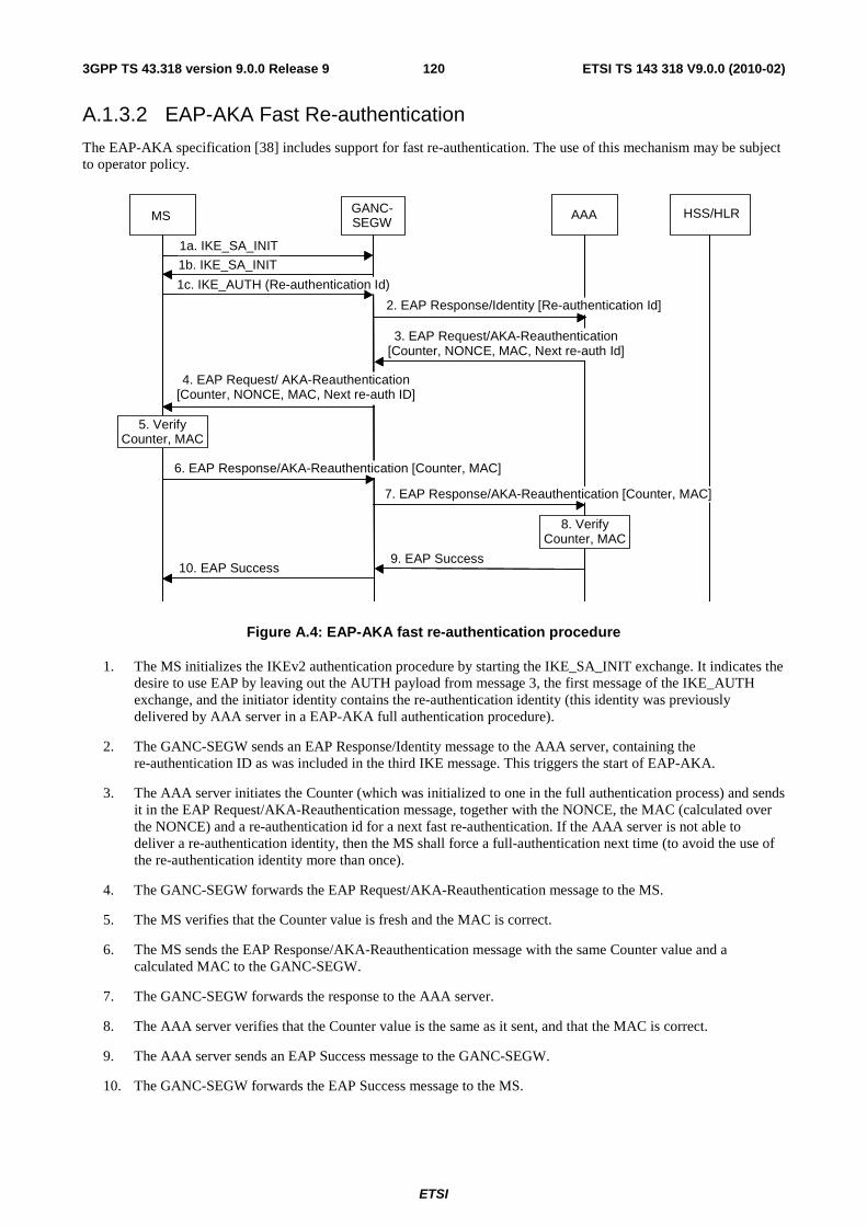
ETSI
ETSI TS 143 318 V9.0.0 (2010-02)1203GPP TS 43.318 version 9.0.0 Release 9
A.1.3.2 EAP-AKA Fast Re-authentication
The EAP-AKA specification [38] includes support for fast re-authentication. The use of this mechanism may be subject to operator policy.
AAA MS
GANC- SEGW
2. EAP Response/Identity [Re-authentication Id]
3. EAP Request/AKA-Reauthentication [Counter, NONCE, MAC, Next re-auth Id]
6. EAP Response/AKA-Reauthentication [Counter, MAC]
9. EAP Success 10. EAP Success
4. EAP Request/ AKA-Reauthentication [Counter, NONCE, MAC, Next re-auth ID]
7. EAP Response/AKA-Reauthentication [Counter, MAC]
1a. IKE_SA_INIT
1b. IKE_SA_INIT
1c. IKE_AUTH (Re-authentication Id)
HSS/HLR
5. Verify Counter, MAC
8. Verify Counter, MAC
Figure A.4: EAP-AKA fast re-authentication procedure
1. The MS initializes the IKEv2 authentication procedure by starting the IKE_SA_INIT exchange. It indicates the desire to use EAP by leaving out the AUTH payload from message 3, the first message of the IKE_AUTH exchange, and the initiator identity contains the re-authentication identity (this identity was previously delivered by AAA server in a EAP-AKA full authentication procedure).
2. The GANC-SEGW sends an EAP Response/Identity message to the AAA server, containing the re-authentication ID as was included in the third IKE message. This triggers the start of EAP-AKA.
3. The AAA server initiates the Counter (which was initialized to one in the full authentication process) and sends it in the EAP Request/AKA-Reauthentication message, together with the NONCE, the MAC (calculated over the NONCE) and a re-authentication id for a next fast re-authentication. If the AAA server is not able to deliver a re-authentication identity, then the MS shall force a full-authentication next time (to avoid the use of the re-authentication identity more than once).
4. The GANC-SEGW forwards the EAP Request/AKA-Reauthentication message to the MS.
5. The MS verifies that the Counter value is fresh and the MAC is correct.
6. The MS sends the EAP Response/AKA-Reauthentication message with the same Counter value and a calculated MAC to the GANC-SEGW.
7. The GANC-SEGW forwards the response to the AAA server.
8. The AAA server verifies that the Counter value is the same as it sent, and that the MAC is correct.
9. The AAA server sends an EAP Success message to the GANC-SEGW.
10. The GANC-SEGW forwards the EAP Success message to the MS.

ETSI
ETSI TS 143 318 V9.0.0 (2010-02)1213GPP TS 43.318 version 9.0.0 Release 9
A.2 Profile of IKEv2 IKEv2, as specified in [32], contains a number of options, where some are not needed for the purposes of this specification and others are required. IKEv2 is therefore profiled in this section. When IKEv2 is used in the context of this specification the profile specified in this section shall be supported. The profile is aligned with 3GPP WLAN Interworking, Scenario 3 as defined in 3GPP TS 33.234 [9].
Access to GAN services follows a VPN-like approach. In [34] can be found a set of recommendations of IKEv2 profiles, suitable for VPN-like solutions. On the other hand, [33] sets rules and recommendations for individual algorithms support. Following recommendation from both papers, the below three profiles shall be supported by the MS and GANC-SEGW - GANC-SGW shall support all three profiles, while the MS shall support at least one of the three profiles in order of preference stated below:
• First cryptographic suite:
- Confidentiality: AES with fixed key length in CBC mode. The key length is set to 128 bits (also known as ENCR_AES_CBC) per RFC 3602 [22].
- Pseudo-random function: HMAC-SHA1 (also known as PRF_HMAC_SHA1) per RFC 2104 [23].
- Integrity: HMAC-SHA1-96 (also known as AUTH_HMAC_SHA1_96) per RFC 2404 [25].
- Diffie-Hellman group 2 (1024-bit MODP) per RFC 2409 [42].
• Second cryptographic suite:
- Confidentiality: 3DES in CBC mode (also known as ENCR_3DES) per RFC 2451 [21].
- Pseudo-random function: HMAC-SHA1 (also known as PRF_HMAC_SHA1) per RFC 2104 [23].
- Integrity: HMAC-SHA1-96 (also known as AUTH_HMAC_SHA1_96) per RFC 2404 [25].
- Diffie-Hellman group 2 (1024-bit MODP) per RFC 2409 [42].
• Third cryptographic suite:
- Confidentiality: AES with fixed key length in CBC mode. The key length is set to 128 bits (also known as ENCR_AES_CBC) per RFC 3602 [22].
- Pseudo-random function: AES-XCBC-PRF-128 (also known as PRF_AES128_XCBC) per RFC 4434 [28].
- Integrity: AES-XCBC-MAC-96 (also known as AUTH_AES_PRF_128) per RFC 3566 [27].
- Diffie-Hellman group 2 (1024-bit MODP) per RFC 2409 [42].
A.3 Profile of IPsec ESP The IPsec specification contains a number of options for the cryptographic algorithms for IPsec ESP. In order to limit the implementation requirements, a specified profile of IPsec ESP is applied. The profile is aligned with 3GPP WLAN Interworking, Scenario 3 as defined in 3GPP TS 33.234 [9].
Rules and recommendations in [33] and [34] have been followed, as in case of IKEv2. The below three profiles shall be supported by the MS and GANC-SEGW - GANC-SEGW shall support all three profiles, while the MS shall support at least one of the three profiles in order of preference stated below:
• First cryptographic suite:
- Confidentiality: AES with fixed key length in CBC mode. The key length is set to 128 bits (also known as ENCR_AES_CBC) per RFC 3602 [22].
- Integrity: HMAC-SHA1-96 (also known as AUTH_HMAC_SHA1_96) per RFC 2404 [25].
- Tunnel mode must be used.

ETSI
ETSI TS 143 318 V9.0.0 (2010-02)1223GPP TS 43.318 version 9.0.0 Release 9
• Second cryptographic suite:
- Confidentiality: 3DES in CBC mode (also known as ENCR_3DES) per RFC 2451 [21].
- Integrity: HMAC-SHA1-96 (also known as PRF_HMAC_SHA1). The key length is 160 bits, according to RFC 2104 and RFC 2404 [25].
- Tunnel mode must be used.
• Third cryptographic suite:
- Confidentiality: AES with 128-bit keys in CBC mode. The key length is set to 128 bits (also known as ENCR_AES_CBC) per RFC 3602 [22].
- Integrity: AES-XCBC-MAC-96 (also known as AUTH_AES_PRF_128) per RFC 3566 [27].
- Tunnel mode must be used.

ETSI
ETSI TS 143 318 V9.0.0 (2010-02)1233GPP TS 43.318 version 9.0.0 Release 9
Annex B (informative): Configuration Information
B.1 GAN A/Gb mode ARFCN/BSIC for handover-to-GAN Selection of ARFCN may use the following guidelines:
1. The ARFCN should not be allocated from the operator's existing BCCH pool so that a scarce BCCH is not used.
2. The ARFCN maybe desired to be the same unique number across the whole operator network to minimize the BSS configuration effort.
The following are available options for the selection of the ARFCN:
1. Ideally, the GAN is assigned an ARFCN value, which is not in the frequency bands currently used by the operator.
2. Typically, different PLMNs in the same country have disjoint frequency allocations. For each PLMN, some of the frequencies are reserved for BCCH beacon; BCCH will be transmitted with constant max power on time slot 0. Other frequencies are dedicated as traffic channels. The GAN ARFCN could use any non-BCCH frequency from the carrier's existing frequency pool. Standard GSM MSs will be able to tune onto this channel but will not be able to find the FCCH burst.
3. Alternatively, in a PCS-only (1 900 MHz) network, ARFCN can be any value falling within the GSM (900 MHz) or DCS (1 800 MHz) band. Standard GSM handsets operating in PCS-only mode will ignore this ARFCN. Tri-band handsets supporting automatic band change will not be able to find a BCCH on the associated frequency.
B.2 GAN Iu mode UARFCN/PSC for handover-to-GAN Selection of the UTRA Absolute RF Channel Number (UARFCN) and Primary Scrambling Code (PSC) may use the following guidelines:
1. The GAN UARFCN may be allocated from the operator's existing UARFCN pool.
2. The GAN UARFCN should be the same as the macro network UARFCN value of the current serving UTRAN cell for the MS, to avoid the need to require the MS to do inter-frequency measurements for UTRAN-to-GAN handover purposes (e.g., requiring that the MS operate in compressed mode). The GANC may use the downlink UARFCN of the UTRAN cells in the current active set, received from the MS in the GA-RC REGISTER REQUEST message, when deciding which UARFCN to return to the MS in the GA-RC REGISTER ACCEPT message. Note that all UTRAN cells in the current active set use the same downlink UARFCN.
3. The GAN PSC may be desired to be the same unique number across the whole operator network to minimize the RNS configuration effort.
B.2.1 Cell Measurement Quantities and Values As described in clause 9.14.2 (CS case) and clause 9.23.2 (PS case), handover from UTRAN to GAN Iu mode requires that the MS include information corresponding to the registered GAN Iu mode cell in the Measurement Report message sent to the RNC. The MS reports the 'highest signal quality' for the GAN Iu mode cell. This is not the actual measured signal level on the GAN, rather an artificial value allowing the MS to indicate preference for the GAN.
The RNC may request that the MS report either the downlink Ec/No (received energy per chip divided by the noise power spectral density in the band) or downlink RSCP (Received Signal Code Power) quantities. The MS shall report maximum values for the Ec/No or RSCP quantities. The maximum value of Ec/No is 63. The maximum value of RSCP is 91.

ETSI
ETSI TS 143 318 V9.0.0 (2010-02)1243GPP TS 43.318 version 9.0.0 Release 9
Annex C (informative): Identifiers in GAN
C.1 Identifiers for MSs and generic IP access network The following are the key MS and generic IP access network addressing parameters.
1. The IMSI associated with the (U)SIM in the terminal.
- The MS provide the IMSI to the GANC during the Registration procedure. The GANC maintains a record for each registered MS. For example, IMSI is used by the GANC to index the appropriate MS record when the GANC receives a BSSMAP PAGING message.
2. Public IP Address of the MS.
- The Public IP address of MS is the source IP present in the outermost IP header of packets received from the MS by the GANC-SEGW. If available, this identifier may be used by the GANC to support location services and fraud detection or by service providers to signal Managed IP networks IP flows that require special QoS treatment.
3. The generic IP access network point of attachment address (AP-ID).
- The MS provides the AP-ID to the GANC at Registration. The AP-ID may be used by the GANC to support location services or by the service provider to restrict GAN access to authorized APs.
C.2 Cell identifiers for GAN A/Gb mode
C.2.1 GAN Cell Id for Location Services & Billing Cell Global Identities (CGI) may be used to perform location-basing routeing of a call for services such as: emergency services; operators; announcements and freephone numbers. Cell identities can be also used by the core network to identify the location of where a call was originated/terminated for charging purposes. The GANC provides a CGI to the core network indicating the GAN cell.
C.2.1.1 Assigning GAN Cell Id based on GSM location
In the GAN architecture, the MS has a direct IP-based connection to the GANC. The GAN coverage area may overlay the GERAN coverage area. Logical mapping of GAN Cells to a CGI can be completed at various resolutions, for example (but not limited to):
• a GAN cell for each GSM cell;
• a GAN cell for each GSM routeing area; or
• a GAN cell for each GSM location area.
A single GANC could represent one or more cells (CGI) in one or more location areas (LAI).

ETSI
ETSI TS 143 318 V9.0.0 (2010-02)1253GPP TS 43.318 version 9.0.0 Release 9
C.2.2 GAN Cell Id for handover-to-GAN The GAN cell id used for location and charging can be independent from the GAN cell id used for handover.
A single GANC represents a single cell, and referred to as GAN cell, for the purpose of handover from GERAN to GAN. This "handover-GANC-CGI" is not visible to the MS. It is only used in the GERAN and CN for identifying a target cell (i.e. target GANC) for handover from GERAN to GAN, and ignored by the GANC, when received during the handover via the A-interface.
The "handover-GANC-CGI" assigned to the GANC is configured as the target handover cell in all neighbouring GERAN cells (in the ARFCN/BSIC-to-CGI mapping table). Neighbouring GERAN cells are those whose service area "overlaps" the GANC service area, for the purpose of handover.
For example, neighbour cells are:
• All GERAN cells attached to the same MSC as the GANC.
• All GERAN cells attached to a different MSC but that can handover to the MSC to which the GANC is attached.
When the MS reports measurements to the GERAN BSS on the GAN cell identified by its ARFCN/BSIC, then the GERAN BSS maps the ARFCN/BSIC to the "handover-GANC-CGI" through its mapping table, and is thus able to identify the target cell (GANC) for handover-to-GAN.
C.2.3 GAN ARFCN/BSIC for handover-to-GAN The GERAN-to-GAN handover method makes use of an RF channel number (ARFCN) and base station identity code (BSIC) parameters to identify the GAN target cell. All GANCs in a given operator domain can share the same ARFCN/BSIC values, if there is a single GANC neighbour per GSM cell. This ARFCN/BSIC is indicated to the MS by the GANC during GAN registration.
The selection of the RF channel number (ARFCN) used for the UTRAN to GAN handover procedure should not correspond to a channel from any frequency band defined in 3GPP TS 45.005, to avoid UEs not requiring compressed mode for GSM measurements from unnecessarily powering up their GSM receivers.
C.3 (void)

ETSI
ETSI TS 143 318 V9.0.0 (2010-02)1263GPP TS 43.318 version 9.0.0 Release 9
Annex D (informative): Change history
Change history Date TSG GERAN# TSG Doc. CR Rev Subject/Comment Old New 2005-01 23 GP-050544 - - Version for Release 6 approved at TSG
GERAN#23 2.0.0 6.0.0
2005-04 24 GP-050934 001 Introduction of the support for Cell Broadcast in GAN
6.0.0 6.1.0
2005-06 25 GP-051594 003 Editorial correction PCCO to GAN 6.1.0 6.2.0 2005-06 25 GP-051595 004 GERAN preferred mode MS behaviour 6.1.0 6.2.0 2005-06 25 GP-051763 005 1 GAN only mode MS behaviour 6.1.0 6.2.0 2005-06 25 GP-051704 007 Clarification to the CS charging description for
GAN 6.1.0 6.2.0
2005-09 26 GP-052142 0009 Removal of addressing for the Generic Access Network
6.2.0 6.3.0
2005-11 27 GP-052796 0010 1 Clarifications to GAN Stage 2 6.3.0 6.4.0 2006-01 28 GP-060460 0008 6 Introduction of the Inter RAT Handover to GAN
definition 6.4.0 6.5.0
2006-01 28 GP-060391 0012 1 Clarifications to GAN Stage 2 6.4.0 6.5.0 2006-04 29 GP-060929 0013 1 Clarification on GANC Selection 6.5.0 6.6.0 2006-04 29 GP-060924 0014 1 Rove-in description alignment with "Call re-
establishment" 6.5.0 6.6.0
2006-05 30 GP-061188 0016 Clarification of GAN selection when MS in GERAN/UTRAN preferred mode
6.6.0 6.7.0
2006-11 32 GP-062357 0018 1 GAN cell selection : Alignment with stage 3 6.7.0 6.8.0 2006-11 32 GP-062272 0019 Cryptographic algorithm update 6.7.0 6.8.0 2006-11 32 GP-062119 0017 2 PS Handover Support for GAN 6.8.0 7.0.0 2007-02 33 GP-070499 0021 3 Correction of BSSMAP messages in the Mobile
Terminated Call Flow 7.0.0 7.1.0
2007-05 34 GP-071010 0022 1 GERAN/UTRAN cells scan for rove-out in GAN mode
7.1.0 7.2.0
2007-08 35 GP-071522 0024 3 Editorial corrections to GERAN and GSM references for GAN emergency procedures
7.2.0 7.3.0
2007-11 36 GP-071945 0028 1 Change of specification title 7.3.0 7.4.0 2007-11 36 GP-071977 0025 3 Addition of GAN Iu Mode functionality to GAN
Stage 2 7.4.0 8.0.0
2007-11 36 GP-072013 0026 2 Maintaining PLMN Continuity in GAN Mode 7.4.0 8.0.0 2008-02 37 GP-080397 0029 2 Supplementing GAN Registration Update with
UARFCN 8.0.0 8.1.0
2008-05 38 GP-080844 0030 1 Stage 2 changes to align with GAN Stage 3 8.1.0 8.2.0 2008-05 38 GP-080845 0033 1 Stage 2 clarification of MS deregistration after
handover from GAN to GERAN/UTRAN 8.1.0 8.2.0
2008-08 39 GP-081390 0034 2 Supporting Multiple GAN Modes per PLMN 8.2.0 8.3.0 2009-02 41 GP-090164 0036 Clarification on the GANC Selection Process for
PLMN Continuity 8.3.0 8.4.0
2009-02 41 GP-090165 0037 Clarification on Maintaining PLMN Continuity in GAN Mode
8.3.0 8.4.0
2009-12 44 Version for Release 9 8.4.0 9.0.0

ETSI
ETSI TS 143 318 V9.0.0 (2010-02)1273GPP TS 43.318 version 9.0.0 Release 9
History
Document history
V9.0.0 February 2010 Publication