ts 136 143 - v8.3.0 - lte; evolved universal terrestrial ... · etsi ts 136 143 v8.3.0 (2010-02)...
TRANSCRIPT

ETSI TS 136 143 V8.3.0 (2010-02)
Technical Specification
LTE;Evolved Universal Terrestrial Radio Access (E-UTRA);
FDD repeater conformance testing (3GPP TS 36.143 version 8.3.0 Release 8)

ETSI
ETSI TS 136 143 V8.3.0 (2010-02)13GPP TS 36.143 version 8.3.0 Release 8
Reference RTS/TSGR-0436143v830
Keywords LTE
ETSI
650 Route des Lucioles F-06921 Sophia Antipolis Cedex - FRANCE
Tel.: +33 4 92 94 42 00 Fax: +33 4 93 65 47 16
Siret N° 348 623 562 00017 - NAF 742 C
Association à but non lucratif enregistrée à la Sous-Préfecture de Grasse (06) N° 7803/88
Important notice
Individual copies of the present document can be downloaded from: http://www.etsi.org
The present document may be made available in more than one electronic version or in print. In any case of existing or perceived difference in contents between such versions, the reference version is the Portable Document Format (PDF).
In case of dispute, the reference shall be the printing on ETSI printers of the PDF version kept on a specific network drive within ETSI Secretariat.
Users of the present document should be aware that the document may be subject to revision or change of status. Information on the current status of this and other ETSI documents is available at
http://portal.etsi.org/tb/status/status.asp
If you find errors in the present document, please send your comment to one of the following services: http://portal.etsi.org/chaircor/ETSI_support.asp
Copyright Notification
No part may be reproduced except as authorized by written permission. The copyright and the foregoing restriction extend to reproduction in all media.
© European Telecommunications Standards Institute 2010.
All rights reserved.
DECTTM, PLUGTESTSTM, UMTSTM, TIPHONTM, the TIPHON logo and the ETSI logo are Trade Marks of ETSI registered for the benefit of its Members.
3GPPTM is a Trade Mark of ETSI registered for the benefit of its Members and of the 3GPP Organizational Partners. LTE™ is a Trade Mark of ETSI currently being registered
for the benefit of its Members and of the 3GPP Organizational Partners. GSM® and the GSM logo are Trade Marks registered and owned by the GSM Association.

ETSI
ETSI TS 136 143 V8.3.0 (2010-02)23GPP TS 36.143 version 8.3.0 Release 8
Intellectual Property Rights IPRs essential or potentially essential to the present document may have been declared to ETSI. The information pertaining to these essential IPRs, if any, is publicly available for ETSI members and non-members, and can be found in ETSI SR 000 314: "Intellectual Property Rights (IPRs); Essential, or potentially Essential, IPRs notified to ETSI in respect of ETSI standards", which is available from the ETSI Secretariat. Latest updates are available on the ETSI Web server (http://webapp.etsi.org/IPR/home.asp).
Pursuant to the ETSI IPR Policy, no investigation, including IPR searches, has been carried out by ETSI. No guarantee can be given as to the existence of other IPRs not referenced in ETSI SR 000 314 (or the updates on the ETSI Web server) which are, or may be, or may become, essential to the present document.
Foreword This Technical Specification (TS) has been produced by ETSI 3rd Generation Partnership Project (3GPP).
The present document may refer to technical specifications or reports using their 3GPP identities, UMTS identities or GSM identities. These should be interpreted as being references to the corresponding ETSI deliverables.
The cross reference between GSM, UMTS, 3GPP and ETSI identities can be found under http://webapp.etsi.org/key/queryform.asp.

ETSI
ETSI TS 136 143 V8.3.0 (2010-02)33GPP TS 36.143 version 8.3.0 Release 8
Contents
Intellectual Property Rights ................................................................................................................................ 2
Foreword ............................................................................................................................................................. 2
Foreword ............................................................................................................................................................. 7
1 Scope ........................................................................................................................................................ 8
2 References ................................................................................................................................................ 8
3 Definitions, symbols and abbreviations ................................................................................................... 8
3.1 Definitions .......................................................................................................................................................... 8
3.2 Symbols .............................................................................................................................................................. 9
3.3 Abbreviations ................................................................................................................................................... 10
4 General test conditions and declarations ................................................................................................ 10
4.1 Measurement uncertainties and test requirements ............................................................................................ 10
4.1.1 General ........................................................................................................................................................ 10
4.1.2 Acceptable uncertainty of test system ......................................................................................................... 10
4.1.2.1 Measurement of Repeater ..................................................................................................................... 11
4.1.2.2 Interpretation of measurement results ................................................................................................... 12
4.2 Regional requirements ...................................................................................................................................... 13
4.3 Selection of configurations for testing.............................................................................................................. 13
4.4 Repeater configurations .................................................................................................................................... 14
4.4.1 Power supply options .................................................................................................................................. 14
4.4.2 Combining of repeaters ............................................................................................................................... 14
4.5 Manufacturer"s declarations of regional and optional requirements ................................................................ 14
4.5.1 Operating band and frequency range .......................................................................................................... 14
4.5.2 Channel bandwidth ..................................................................................................................................... 14
4.5.3 Repeater output power ................................................................................................................................ 14
4.5.4 Spurious emissions Category ...................................................................................................................... 14
4.5.5 Additional operating band unwanted emissions ......................................................................................... 15
4.5.6 Co-existence with other systems ................................................................................................................. 15
4.5.7 Co-location with base stations .................................................................................................................... 15
4.6 Specified frequency range ................................................................................................................................ 15
4.7 Format and interpretation of tests ..................................................................................................................... 15
5 Operating bands and channel arrangement ............................................................................................. 16
5.1 General ............................................................................................................................................................. 16
5.2 Void .................................................................................................................................................................. 16
5.3 Void .................................................................................................................................................................. 16
5.4 Void .................................................................................................................................................................. 16
5.5 Operating bands ................................................................................................................................................ 16
5.6 Channel bandwidth ........................................................................................................................................... 17
5.7 Channel arrangement ........................................................................................................................................ 18
5.7.1 Channel spacing .......................................................................................................................................... 18
5.7.2 Channel raster ............................................................................................................................................. 18
5.7.3 Carrier frequency and EARFCN ................................................................................................................. 18
6 Output power .......................................................................................................................................... 19
6.1 Definition and applicability .............................................................................................................................. 19
6.2 Minimum requirement ...................................................................................................................................... 19
6.3 Test purpose ..................................................................................................................................................... 19
6.4 Method of test ................................................................................................................................................... 19
6.4.1 Initial conditions ......................................................................................................................................... 19
6.4.2 Procedure .................................................................................................................................................... 19
6.5 Test requirements ............................................................................................................................................. 20
7 Frequency stability ................................................................................................................................. 20
7.1 Definition and applicability .............................................................................................................................. 20

ETSI
ETSI TS 136 143 V8.3.0 (2010-02)43GPP TS 36.143 version 8.3.0 Release 8
7.2 Minimum requirements .................................................................................................................................... 20
7.3 Test purpose ..................................................................................................................................................... 20
7.4 Method of test ................................................................................................................................................... 20
7.5 Test requirement ............................................................................................................................................... 21
8 Out of band gain ..................................................................................................................................... 21
8.1 Definition and applicability .............................................................................................................................. 21
8.2 Minimum requirements .................................................................................................................................... 21
8.3 Test purpose ..................................................................................................................................................... 21
8.4 Method of test ................................................................................................................................................... 21
8.4.1 Initial conditions ......................................................................................................................................... 21
8.4.2 Procedure .................................................................................................................................................... 21
8.5 Test requirements ............................................................................................................................................. 22
9 Unwanted emissions ............................................................................................................................... 22
9.1 Operating band unwanted emissions ................................................................................................................ 22
9.1.1 Definition and applicability ........................................................................................................................ 22
9.1.2 Minimum requirements ............................................................................................................................... 22
9.1.3 Test purpose ................................................................................................................................................ 23
9.1.4 Method of test ............................................................................................................................................. 23
9.1.4.1 Initial conditions ................................................................................................................................... 23
9.1.4.2 Procedures ............................................................................................................................................. 23
9.1.5 Test requirements ........................................................................................................................................ 24
9.1.5.1 Operating band unwanted emission (Category A) ................................................................................ 24
9.1.5.2 Operating band unwanted emissions (Category B) ............................................................................... 26
9.1.5.2.1 Category B test requirements (Option 1) ......................................................................................... 26
9.1.5.2.2 Category B test requirements (Option 2) ......................................................................................... 29
9.1.5.3 Additional requirements ........................................................................................................................ 30
9.1.5.4 Protection of the BS receiver in the operating band .............................................................................. 31
9.2 Spurious emissions ........................................................................................................................................... 32
9.2.1 Definition and applicability ........................................................................................................................ 32
9.2.2 Minimum requirements ............................................................................................................................... 32
9.2.3 Test purpose ................................................................................................................................................ 32
9.2.4 Method of test ............................................................................................................................................. 32
9.2.4.1 Initial conditions ................................................................................................................................... 32
9.2.4.2 Procedures ............................................................................................................................................. 32
9.2.5 Test requirements ........................................................................................................................................ 33
9.2.5.1 Spurious emission (Category A) ........................................................................................................... 33
9.2.5.2 Spurious emission (Category B) ........................................................................................................... 33
9.2.5.3 Co-existence with other systems in the same geographical area ........................................................... 33
9.2.5.4 Co-location with base stations............................................................................................................... 38
10 Error Vector Magnitude (EVM) ............................................................................................................. 41
10.1 Downlink Error Vector Magnitude................................................................................................................... 41
10.1.1 Definition and applicability ........................................................................................................................ 41
10.1.2 Minimum requirements ............................................................................................................................... 41
10.1.3 Test purpose ................................................................................................................................................ 41
10.1.4 Method of test ............................................................................................................................................. 41
10.1.4.1 Initial conditions ................................................................................................................................... 41
10.1.4.2 Procedure .............................................................................................................................................. 42
10.1.5 Test requirement ......................................................................................................................................... 42
10.2 Uplink Error Vector Magnitude ....................................................................................................................... 42
10.2.1 Definition and applicability ........................................................................................................................ 42
10.2.2 Minimum requirements ............................................................................................................................... 42
10.2.3 Test purpose ................................................................................................................................................ 42
10.2.4 Method of test ............................................................................................................................................. 42
10.2.4.1 Initial conditions ................................................................................................................................... 42
10.2.4.2 Procedure .............................................................................................................................................. 42
10.2.5 Test requirement ......................................................................................................................................... 43
11 Input intermodulation ............................................................................................................................. 43
11.1 Definition and applicability .............................................................................................................................. 43
11.2 Minimum requirements .................................................................................................................................... 43

ETSI
ETSI TS 136 143 V8.3.0 (2010-02)53GPP TS 36.143 version 8.3.0 Release 8
11.3 Test purpose ..................................................................................................................................................... 43
11.4 Method of test ................................................................................................................................................... 43
11.4.1 Initial conditions ......................................................................................................................................... 43
11.4.2 Procedure .................................................................................................................................................... 44
11.5 Test requirements ............................................................................................................................................. 44
11.5.1 General requirement ................................................................................................................................... 44
11.5.2 Co-location with BS in other systems ......................................................................................................... 44
11.5.3 Co-existence with other systems ................................................................................................................. 47
12 Output intermodulation .......................................................................................................................... 50
12.1 Definition and applicability .............................................................................................................................. 50
12.2 Minimum requirement ...................................................................................................................................... 50
12.3 Test purpose ..................................................................................................................................................... 50
12.4 Method of test ................................................................................................................................................... 50
12.4.1 Initial conditions ......................................................................................................................................... 50
12.1.4.2 Procedure .................................................................................................................................................... 51
12.5 Test Requirements ............................................................................................................................................ 51
13 Adjacent Channel Rejection Ratio (ACRR) ........................................................................................... 51
13.1 Definitions and applicability ............................................................................................................................ 51
13.1.1 Minimum requirements ............................................................................................................................... 51
13.2 Co-existence with UTRA ................................................................................................................................. 51
13.2.1 Minimum requirements ............................................................................................................................... 52
13.2.2 Test purpose ................................................................................................................................................ 52
13.2.3 Method of test ............................................................................................................................................. 52
13.2.3.1 Initial conditions ................................................................................................................................... 52
13.2.3.2 Procedure .............................................................................................................................................. 52
13.2.3.3 Test Requirements ................................................................................................................................. 52
Annex A (normative): Environmental requirements for the Repeater ........................................... 53
A.1 General ................................................................................................................................................... 53
A.2 Normal test environment ........................................................................................................................ 53
A.3 Extreme test environment ....................................................................................................................... 53
A.3.1 Extreme temperature ............................................................................................................................. 53
A.4 Vibration ................................................................................................................................................. 54
A.5 Power supply .......................................................................................................................................... 54
A.6 Measurement of test environments ......................................................................................................... 54
Annex B (informative): Test tolerances and derivation of test requirements ................................... 55
Annex C (informative): Measurement system set-up .......................................................................... 58
C.1 Maximum output power ......................................................................................................................... 58
C.2 Frequency stability ................................................................................................................................. 58
C.3 Out of band gain ..................................................................................................................................... 59
C.4 Unwanted emission: Operating band unwanted emission ...................................................................... 59
C.5 Unwanted emission: Spurious emission ................................................................................................. 60
C.6 Modulation Accuracy: Error Vector Magnitude .................................................................................... 60
C.7 Input intermodulation ............................................................................................................................. 61
C.8 Output Intermodulation .......................................................................................................................... 61
C.9 Adjacent Channel Rejection Ratio ......................................................................................................... 62
Annex D (normative): Repeater stimulus signals .............................................................................. 63
D.1 Repeater stimulus signal 1 ...................................................................................................................... 63

ETSI
ETSI TS 136 143 V8.3.0 (2010-02)63GPP TS 36.143 version 8.3.0 Release 8
D.2 Repeater stimulus signal 2 ...................................................................................................................... 63
D.3 Repeater stimulus signal 3 ...................................................................................................................... 63
D.4 Repeater stimulus signal 4 ...................................................................................................................... 64
D.5 Repeater stimulus signal spectral purity requirements ........................................................................... 64
Annex E (informative): Change history ............................................................................................... 65
History .............................................................................................................................................................. 66

ETSI
ETSI TS 136 143 V8.3.0 (2010-02)73GPP TS 36.143 version 8.3.0 Release 8
Foreword This Technical Specification has been produced by the 3rd Generation Partnership Project (3GPP).
The contents of the present document are subject to continuing work within the TSG and may change following formal TSG approval. Should the TSG modify the contents of the present document, it will be re-released by the TSG with an identifying change of release date and an increase in version number as follows:
Version x.y.z
where:
x the first digit:
1 presented to TSG for information;
2 presented to TSG for approval;
3 or greater indicates TSG approved document under change control.
Y the second digit is incremented for all changes of substance, i.e. technical enhancements, corrections, updates, etc.
z the third digit is incremented when editorial only changes have been incorporated in the document.
ETSI
ETSI TS 136 143 V8.3.0 (2010-02)83GPP TS 36.143 version 8.3.0 Release 8
1 Scope The present document specifies the Radio Frequency (RF) test methods and conformance requirements for E-UTRA FDD Repeater. These have been derived from, and are consistent with the E-UTRA FDD repeater specifications defined in [2].
2 References The following documents contain provisions which, through reference in this text, constitute provisions of the present document.
• References are either specific (identified by date of publication, edition number, version number, etc.) or non-specific.
• For a specific reference, subsequent revisions do not apply.
• For a non-specific reference, the latest version applies. In the case of a reference to a 3GPP document (including a GSM document), a non-specific reference implicitly refers to the latest version of that document in the same Release as the present document.
[1] 3GPP TR 21.905: 'Vocabulary for 3GPP Specifications'.
[2] 3GPP TS 36.106: 'Evolved Universal Terrestrial Radio Access (E-UTRA); FDD repeater radio transmission and reception'.
[3] ITU-R Recommendation M.1545: 'Measurement uncertainty as it applies to test limits for the terrestrial component of International Mobile Telecommunications-2000'.
[4] ITU-R recommendation SM.329: 'Unwanted emissions in the spurious domain'.
[5] 3GPP TR 25.942: 'Radio Frequency (RF) system scenarios'.
[6] IEC 60721-3-3 (2002): 'Classification of environmental conditions – Part 3: Classification of groups of environmental parameters and their severities – Section 3: Stationary use at weather protected locations'.
[7] IEC 60721-3-4 (1995): 'Classification of environmental conditions – Part 3: Classification of groups of environmental parameters and their severities – Section 4: Stationary use at non-weather protected locations'.
[8] IEC 60068-2-1 (2007): 'Environmental testing – Part 2: Tests. Tests A: Cold'.
[9] IEC 60068-2-2 (2007): 'Environmental testing – Part 2: Tests. Tests B: Dry heat'.
[10] IEC 60068-2-6 (2007): 'Environmental testing – Part 2: Tests – Test Fc: Vibration (sinusoidal)'.
[11] 3GPP TS 36.141: 'Evolved Universal Terrestrial Radio Access (E-UTRA); Base Station (BS) conformance testing'.
[12] 3GPP TS 36.521-1: 'Evolved Universal Terrestrial Radio Access (E-UTRA); User Equipment (UE) conformance specification; Radio transmission and reception; Part 1: Conformance testing'.
3 Definitions, symbols and abbreviations
3.1 Definitions For the purposes of the present document, the terms and definitions given in TR 21.905 [1] and the following apply. A term defined in the present document takes precedence over the definition of the same term, if any, in TR 21.905 [1].

ETSI
ETSI TS 136 143 V8.3.0 (2010-02)93GPP TS 36.143 version 8.3.0 Release 8
Carrier: The modulated waveform conveying the E-UTRA or UTRA physical channels
Channel bandwidth: The RF bandwidth supporting a single E-UTRA RF carrier with the transmission bandwidth configured in the uplink or downlink of a cell. The channel bandwidth is measured in MHz and is used as a reference for transmitter and receiver RF requirements.
Channel edge: The lowest and highest frequency of the E-UTRA carrier, separated by the channel bandwidth.
Donor coupling loss: is the coupling loss between the repeater and the donor base station.
Downlink: Signal path where base station transmits and mobile receives.
Downlink operating band: The part of the operating band designated for downlink.
Maximum output power, Pmax: This is the mean power level per carrier measured at the antenna connector of the Repeater in specified reference condition.
Operating band: A frequency range in which E-UTRA operates (paired or unpaired), that is defined with a specific set of technical requirements.
NOTE1: The operating band(s) for an E-UTRA Repeater is declared by the manufacturer according to the designations in clause 5.5 table 5.5-1.
NOTE2: Unless specified, operating band refers to the uplink operating band and downlink operating band.
Output power, Pout: This is the mean power of one carrier at maximum repeater gain delivered to a load with resistance equal to the nominal load impedance of the transmitter.
Pass band: The repeater can have one or several pass bands. The pass band is the frequency range that the repeater operates in with operational configuration. This frequency range can correspond to one or several consecutive nominal channels. If they are not consecutive each subset of channels shall be considered as an individual pass band.
Rated output power: Rated output power of the repeater is the mean power level per carrier that the manufacturer has declared to be available at the antenna connector.
Repeater: A device that receives, amplifies and transmits the radiated or conducted RF carrier both in the downlink direction (from the base station to the mobile area) and in the uplink direction (from the mobile to the base station)
Transmission bandwidth: Bandwidth of an instantaneous transmission from a UE or BS, measured in Resource Block units.
Transmission bandwidth configuration: The highest transmission bandwidth allowed for uplink or downlink in a given channel bandwidth, measured in Resource Block units.
Uplink: Signal path where mobile transmits and base station receives.
Uplink operating band: The part of the operating band designated for uplink.
3.2 Symbols For the purposes of the present document, the following symbols apply:
BWChannel Channel bandwidth BWConfig Transmission bandwidth configuration, expressed in MHz, where BWConfig = NRB x 180 kHz in the
uplink and BWConfig = 15 kHz + NRB x 180 kHz in the downlink. BWMeas Measurement bandwidth BWSignal Bandwidth of the repeater input signal filling the repeater pass band FDL_low The lowest frequency of the downlink operating band FDL_high The highest frequency of the downlink operating band FUL_low The lowest frequency of the uplink operating band FUL_high The highest frequency of the uplink operating band f_offset_PB Distance from the channel edge frequency of the first or last channel in the pass band NDL Downlink EARFCN NOffs-DL Offset used for calculating downlink EARFCN NOffs-UL Offset used for calculating uplink EARFCN

ETSI
ETSI TS 136 143 V8.3.0 (2010-02)103GPP TS 36.143 version 8.3.0 Release 8
NRB Transmission bandwidth configuration, expressed in units of resource blocks NUL Uplink EARFCN Pmax Maximum output power Pout Output power
3.3 Abbreviations For the purposes of the present document, the abbreviations given in TR 21.905 [1] and the following apply. An abbreviation defined in the present document takes precedence over the definition of the same abbreviation, if any, in TR 21.905 [1].
ACRR Adjacent Channel Rejection Ratio BS Base Station BW Bandwidth DUT Device Under Test E-TM E-UTRA Test Model EARFCN E-UTRA Absolute Radio Frequency Channel Number EVM Error Vector Magnitude FFS For Further Study IDFT Inverse Discrete Fourier Transform PB Pass Band GSM-R GSM for Railways RRC Root Raised Cosine TBD To be defined TT Test Tolerance
4 General test conditions and declarations Many of the tests in this specification measure a parameter relative to a value that is not fully specified in the E-UTRA specifications. For these tests, the Minimum Requirement is determined relative to a nominal value specified by the manufacturer.
Some requirements for the Repeater may be regional as listed in subclause 4.2.
When specified in a test, the manufacturer shall declare the nominal value of a parameter, or whether an option is supported.
4.1 Measurement uncertainties and test requirements
4.1.1 General
The requirements of this clause apply to all applicable tests in this specification.
The Minimum requirements are given in 36.106 [2] and test requirements are given in this specification. Test Tolerances are defined in Annex B of this specification. Test Tolerances are individually calculated for each test. The Test Tolerances are used to relax the Minimum requirements in 36.106 [2] to create Test Requirements.
4.1.2 Acceptable uncertainty of test system
The maximum acceptable uncertainty of the Test System is specified below for each test, where appropriate. The Test System shall enable the stimulus signals in the test case to be adjusted to within the specified tolerance and the equipment under test to be measured with an uncertainty not exceeding the specified values. All tolerances and uncertainties are absolute values, and are valid for a confidence level of 95 %, unless otherwise stated.
A confidence level of 95% is the measurement uncertainty tolerance interval for a specific measurement that contains 95% of the performance of a population of test equipment.

ETSI
ETSI TS 136 143 V8.3.0 (2010-02)113GPP TS 36.143 version 8.3.0 Release 8
For RF tests, it should be noted that the uncertainties in subclause 4.1.2 apply to the Test System operating into a nominal 50 ohm load and do not include system effects due to mismatch between the DUT and the Test System.
4.1.2.1 Measurement of Repeater
Table 4.1.2-1: Maximum test system uncertainty
Subclause Maximum Test System Uncertainty and Range over which Test System Uncertainty applies
Derivation of Test System Uncertainty
6 Output power ±0,7 dB 7 Frequency stability ±12 Hz
Measurement results of ± 500 Hz
8 Out of band gain ±0,5 dB Calibration of test set-up shall be made without DUT in order to achieve the accuracy
9.1 Operating band unwanted emission (except 9.1.5.4)
±1,5 dB The interference from the signal generator ACLR shall be minimum 10 dB below that of a Base Station according toTS36.141
9.1.5.4 Protection of the BS receiver in the operating band
for results > -60 dBm ±2,0 dB for results < -60 dBm ±3,0 dB
9.2 Spurious emissions In E-UTRA and coexistence receive bands: for results > -60 dBm ±2,0 dB for results < -60 dBm ±3,0 dB Outside above range: emission power 9kHz < f ≤ 4 GHz ±2,0 dB; f > 4 GHz ±4,0 dB. The interference from the signal generator ACLR shall be minimum 10 dB below that of a Base Station according toTS36.141
10 Error vector magnitude [1%] signal analyser, [2%] stimulus signal
Requirement limit shifted by RSS requirement and stimulus signal EVM. Analyser error added to requirement limit.
11 Input intermodulation ±1,2 dB Formula: RSS CW1 level error, 2 x CW2 level error, and measurement error (using all errors = ±0,5 dB)
12 Output intermodulation ±2,1 dB operating band unwanted emission The interference from the signal generator ACLR shall be minimum 10 dB below that of a Base Station For spurious emission: In UTRA and coexistence receive bands: for results > -60 dBm ±2,0 dB for results < -60 dBm ±3,0 dB Outside above range: emission power; 9 kHz < f ≤ 4 GHz ±2,0 dB; f > 4 GHz ±4,0 dB. The interference signal must have a spurious emission level at least 10 dB below the spurious levels required in 9.2.
Formula: RSS 2x Interference signal level error and operating band unwanted emission measurement level error. (1 dB interference signal level error is assumed.)
13 Adjacent channel rejection ratio
±0,7 dB

ETSI
ETSI TS 136 143 V8.3.0 (2010-02)123GPP TS 36.143 version 8.3.0 Release 8
4.1.2.2 Interpretation of measurement results
The measurement results returned by the Test System are compared – without any modification – against the Test Requirements as defined by the Shared Risk principle.
The Shared Risk principle is defined in ITU-R M.1545 [3].
The actual measurement uncertainty of the Test System for the measurement of each parameter shall be included in the test report.
The recorded value for the Test System uncertainty shall be, for each measurement, equal to or lower than the appropriate figure in subclause 4.1.2 of this specification.
If the Test System for a test is known to have a measurement uncertainty greater than that specified in subclause 4.1.2, it is still permitted to use this apparatus provided that an adjustment is made as follows.
Any additional uncertainty in the Test System over and above that specified in subclause 4.1.2 shall be used to tighten the Test Requirement, making the test harder to pass. (For some tests e.g. receiver tests, this may require modification of stimulus signals). This procedure (defined in Annex B) will ensure that a Test System not compliant with subclause 4.1.2 does not increase the chance of passing a device under test where that device would otherwise have failed the test if a Test System compliant with subclause 4.1.2 had been used.

ETSI
ETSI TS 136 143 V8.3.0 (2010-02)133GPP TS 36.143 version 8.3.0 Release 8
4.2 Regional requirements Some requirements in the present document may only apply in certain regions. Table 4.2-1 lists all requirements that may be applied differently in different regions.
Table 4.2-1: List of regional requirements
Clause number
Requirement Comments
5.5 Operating bands Some bands may be applied regionally. 5.6 Channel bandwidth Some channel bandwidths may be applied
regionally. 5.7 Channel arrangement The requirement is applied according to what
operating bands in clause 5.5 that are supported by the Repeater.
6 Output power In certain regions, the minimum requirement for normal conditions may apply also for some conditions outside the range of conditions defined as normal.
9.1.5.1 Operating band unwanted emissions (Category A)
This requirement is mandatory for regions where Category A limits for spurious emissions, as defined in ITU-R Recommendation SM.329 [5] apply.
9.1.5.2 Operating band unwanted emissions (Category B)
This requirement is mandatory for regions where Category B limits for spurious emissions, as defined in ITU-R Recommendation SM.329 [5], apply.
9.1.5.3 Operating band unwanted emissions : Additional requirements
These requirements may be applied regionally for some operating bands.
9.2.5.1 Spurious emissions (Category A) This requirement is mandatory for regions where Category A limits for spurious emissions, as defined in ITU-R Recommendation SM.329 [5] apply.
9.2.5.2 Spurious emissions (Category B) This requirement is mandatory for regions where Category B limits for spurious emissions, as defined in ITU-R Recommendation SM.329 [5], apply.
9.2.5.3 Co-existence with other systems in the same geographical area
These requirements may apply in geographic areas in which both E-UTRA –FDD repeater and a system operating in another frequency band are deployed.
9.2.5.4 Co-location with base stations These requirements may be applied for the protection of other BS receivers when a BS operating in another frequency band is co-located with an E-UTRA-FDD repeater.
11.5.2 Input Intermodulation: Co-location with other systems
These requirements may be applied for the protection of FDD Repeater input when GSM900, DCS1800, PCS1900, GSM850, UTRA FDD, UTRA TDD and/or E-UTRA BS are co-located with an E-UTRA FDD Repeater.
11.5.3 Input Intermodulation: Co-existence with other systems
These requirements may be applied when GSM900, DCS1800, PCS1900, GSM850, UTRA FDD, UTRA TDD and/or E-UTRA BS operating in another frequency band co-exist with an E-UTRA FDD Repeater
4.3 Selection of configurations for testing Most tests in the present document are only performed for a subset of the possible combinations of test conditions. For instance:
- Only one RF channel may be specified to be tested;
- Not all channel bandwidths may be specified to be tested.

ETSI
ETSI TS 136 143 V8.3.0 (2010-02)143GPP TS 36.143 version 8.3.0 Release 8
4.4 Repeater configurations
4.4.1 Power supply options
If the repeater is supplied with a number of different power supply configurations, it may not be necessary to test RF parameters for each of the power supply options, provided that it can be demonstrated that the range of conditions over which the equipment is tested is at least as great as the range of conditions due to any of the power supply configurations.
4.4.2 Combining of repeaters
If the repeater is intended for combination with additional apparatus connected to a repeater port and this combination is supplied as a system, the combination of repeater together with the additional apparatus shall also fulfil the repeater requirements. E.g. if the repeater is intended for combination such that multiple repeaters amplify the same signals into the same ports the combination shall also fulfil the repeater requirements.
An example of such a configuration is shown in figure 4.4-1.
R e p e a te r C o m b ine r / S p li tte r
R e p e a te r
C o m b ine r / S p li tte r
A nte n na c o n ne c to r
A nte n na c o n ne c to r
Te s t p o rt
Te s t p o rt
Figure 4.4-1: Example of repeater configuration
4.5 Manufacturer"s declarations of regional and optional requirements
4.5.1 Operating band and frequency range
The manufacturer shall declare which operating band(s) specified in clause 5.3 that is supported by the Repeater under test and if applicable, which frequency ranges (pass band) within the operating band(s) that the Repeater can operate in. Requirements for other operating bands and frequency ranges (pass band) need not be tested.
4.5.2 Channel bandwidth
The manufacturer shall declare which of the channel bandwidths specified in TS36.106 clause 5.2 that are supported by the Repeater under test. Requirements for other channel bandwidths need not be tested.
4.5.3 Repeater output power
The manufacturer shall declare for the Repeater under test the rated output power.
4.5.4 Spurious emissions Category
The manufacturer shall declare one of the following:

ETSI
ETSI TS 136 143 V8.3.0 (2010-02)153GPP TS 36.143 version 8.3.0 Release 8
a) The Repeater is tested against Category A limits for spurious emissions, as defined in ITU-R Recommendation SM.329 [2]. In this case
- conformance with the operating band unwanted emissions requirements in clause 9.1.5.1 is mandatory, and the requirements specified in clause 9.1.5.2 need not be tested.
- conformance with the spurious emissions requirements in clause 9.2.5.1 is mandatory, and the requirements specified in clause 9.2.5.2 need not be tested.
b) The Repeater is tested against Category B limits for spurious emissions, as defined in ITU-R Recommendation SM.329 [2]. In this case,
- conformance with the operating band unwanted emissions requirements in clause 9.1.5.2 is mandatory, and the requirements specified in clause 9.1.5.1 need not be tested.
- conformance with the spurious emissions requirements in clause 9.2.5.2 is mandatory, and the requirements specified in clause 9.2.5.1 need not be tested.
4.5.5 Additional operating band unwanted emissions
The manufacturer shall declare whether the Repeater under test is intended to operate in geographic areas where additional operating band unwanted emission limits as defined in clause 9.1.5.3 apply. If this is the case, compliance with the test requirements specified in Tables 9.1.5.3-1, 9.1.5.3-2 or 9.1.5.3-3 are mandatory; otherwise these requirements need not be tested.
4.5.6 Co-existence with other systems
The manufacturer shall declare whether the repeater under test is intended to operate in geographic areas where one or more of the systems GSM850, GSM900, DCS1800, PCS1900, UTRA FDD, UTRA TDD, E-UTRA and/or PHS operating in another frequency bands are deployed. If this is the case,
- compliance with the applicable test requirement for spurious emissions specified in clause 9.2.5.3 shall be tested.
- compliance with the applicable test requirement for input intermodulation specified in clause 11.5.3 shall be tested.
4.5.7 Co-location with base stations
The manufacturer shall declare whether the repeater under test is intended to operate co-located with base stations of one or more of the systems GSM850, GSM900, DCS1800, PCS1900, UTRA FDD, UTRA TDD and/or E-UTRA operating in another frequency band. If this is the case,
- compliance with the applicable test requirement for spurious emissions specified in clause 9.2.5.4 shall be tested.
- compliance with the applicable test requirement for input intermodulation specified in clause 11.5.2 shall be tested.
4.6 Specified frequency range <Text will be added.>
4.7 Format and interpretation of tests Each test in the following clauses has a standard format:
X Title
All tests are applicable to all equipment within the scope of the present document, unless otherwise stated.

ETSI
ETSI TS 136 143 V8.3.0 (2010-02)163GPP TS 36.143 version 8.3.0 Release 8
X.1 Definition and applicability
This subclause gives the general definition of the parameter under consideration and specifies whether the test is applicable to all equipment or only to a certain subset. Required manufacturer declarations may be included here.
X.2 Minimum Requirement
This subclause contains the reference to the subclause to the 3GPP reference (or core) specification which defines the Minimum Requirement.
X.3 Test Purpose
This subclause defines the purpose of the test.
X.4 Method of test
X.4.1 Initial conditions
This subclause defines the initial conditions for each test, including the test environment, the RF channels to be tested and the basic measurement set-up.
X.4.2 Procedure
This subclause describes the steps necessary to perform the test and provides further details of the test definition like point of access (e.g. test port), domain (e.g. frequency-span), range, weighting (e.g. bandwidth), and algorithms (e.g. averaging).
X.5 Test Requirement
This subclause defines the pass/fail criteria for the equipment under test. See subclause 4.1.2.2 Interpretation of measurement results.
5 Operating bands and channel arrangement
5.1 General The channel arrangements presented in this clause are based on the operating bands and channel bandwidths defined in the present release of specifications.
NOTE: Other operating bands and channel bandwidths may be considered in future releases.
5.2 Void
5.3 Void
5.4 Void
5.5 Operating bands E-UTRA FDD is designed to operate in the operating bands defined in Table 5.5-1.

ETSI
ETSI TS 136 143 V8.3.0 (2010-02)173GPP TS 36.143 version 8.3.0 Release 8
Table 5.5-1 E-UTRA operating bands
E-UTRA operating
band
Uplink (UL) operating band
Downlink (DL) operating band Duplex
Mode FUL_low – FUL_high FDL_low – FDL_high
1 1920 MHz – 1980 MHz 2110 MHz – 2170 MHz FDD 2 1850 MHz – 1910 MHz 1930 MHz – 1990 MHz FDD 3 1710 MHz – 1785 MHz 1805 MHz – 1880 MHz FDD 4 1710 MHz – 1755 MHz 2110 MHz – 2155 MHz FDD 5 824 MHz – 849 MHz 869 MHz – 894MHz FDD 6 830 MHz – 840 MHz 875 MHz – 885 MHz FDD 7 2500 MHz – 2570 MHz 2620 MHz – 2690 MHz FDD 8 880 MHz – 915 MHz 925 MHz – 960 MHz FDD 9 1749.9 MHz – 1784.9 MHz 1844.9 MHz – 1879.9 MHz FDD 10 1710 MHz – 1770 MHz 2110 MHz – 2170 MHz FDD 11 1427.9 MHz – 1452.9 MHz 1475.9 MHz – 1500.9 MHz FDD 12 698 MHz – 716 MHz 728 MHz – 746 MHz FDD 13 777 MHz – 787 MHz 746 MHz – 756 MHz FDD 14 788 MHz – 798 MHz 758 MHz – 768 MHz FDD … 17 704 MHz – 716 MHz 734 MHz – 746 MHz FDD
5.6 Channel bandwidth Requirements in present document are specified for the channel bandwidths listed in Table 5.6-1.
Table 5.6-1 Transmission bandwidth configuration NRB in E-UTRA channel bandwidths
Channel bandwidth BWChannel [MHz] 1.4 3 5 10 15 20
Transmission bandwidth configuration NRB 6 15 25 50 75 100
Figure 5.6-1 Definition of channel bandwidth and transmission bandwidth configuration for one E-UTRA carrier.

ETSI
ETSI TS 136 143 V8.3.0 (2010-02)183GPP TS 36.143 version 8.3.0 Release 8
Figure 5.6-1 shows the relation between the Channel bandwidth (BWChannel) and the Transmission bandwidth configuration (NRB). The channel edges are defined as the lowest and highest frequencies of the carrier separated by the channel bandwidth, i.e. at FC +/- BWChannel /2.
5.7 Channel arrangement
5.7.1 Channel spacing
The spacing between carriers will depend on the deployment scenario, the size of the frequency block available and the channel bandwidths. The nominal channel spacing between two adjacent E-UTRA carriers is defined as following:
Nominal Channel spacing = (BWChannel(1) + BWChannel(2))/2
where BWChannel(1) and BWChannel(2) are the channel bandwidths of the two respective E-UTRA carriers. The channel spacing can be adjusted to optimize performance in a particular deployment scenario.
5.7.2 Channel raster
The channel raster is 100 kHz for all bands, which means that the carrier centre frequency must be an integer multiple of 100 kHz.
5.7.3 Carrier frequency and EARFCN
The carrier frequency in the uplink and downlink is designated by the E-UTRA Absolute Radio Frequency Channel Number (EARFCN) in the range 0 – 65535. The relation between EARFCN and the carrier frequency in MHz for the downlink is given by the following equation, where FDL_low and NOffs-DL are given in table 5.7.3-1 and NDL is the downlink EARFCN.
FDL = FDL_low + 0.1(NDL – NOffs-DL)
The relation between EARFCN and the carrier frequency in MHz for the uplink is given by the following equation where FUL_low and NOffs-UL are given in table 5.7.3-1 and NUL is the uplink EARFCN.
FUL = FUL_low + 0.1(NUL – NOffs-UL)
Table 5.7.3-1 E-UTRA channel numbers
E-UTRA operating
band
Downlink Uplink
FDL_low [MHz] NOffs-DL Range of NDL FUL_low [MHz] NOffs-UL Range of NUL
1 2110 0 0 – 599 1920 18000 18000 – 18599 2 1930 600 600 − 1199 1850 18600 18600 – 19199 3 1805 1200 1200 – 1949 1710 19200 19200 – 19949 4 2110 1950 1950 – 2399 1710 19950 19950 – 20399 5 869 2400 2400 – 2649 824 20400 20400 – 20649 6 875 2650 2650 – 2749 830 20650 20650 – 20749 7 2620 2750 2750 – 3449 2500 20750 20750 – 21449 8 925 3450 3450 – 3799 880 21450 21450 – 21799 9 1844.9 3800 3800 – 4149 1749.9 21800 21800 – 22149
10 2110 4150 4150 – 4749 1710 22150 22150 – 22749 11 1475.9 4750 4750 – 4999 1427.9 22750 22750 – 22999 12 728 5000 5000 – 5179 698 23000 23000 – 23179 13 746 5180 5180 – 5279 777 23180 23180 – 23279 14 758 5280 5280 – 5379 788 23280 23280 – 23379 … 17 734 5730 5730 – 5849 704 23730 23730 – 23849
NOTE: The channel numbers that designate carrier frequencies so close to the operating band edges that the carrier extends beyond the operating band edge shall not be used. This implies that the first 7, 15, 25, 50, 75 and 100 channel numbers at the lower operating band edge and the last 6, 14, 24, 49, 74 and 99 channel numbers at the upper operating band edge shall not be used for channel bandwidths of 1.4, 3, 5, 10, 15 and 20 MHz respectively.

ETSI
ETSI TS 136 143 V8.3.0 (2010-02)193GPP TS 36.143 version 8.3.0 Release 8
6 Output power
6.1 Definition and applicability Output power, Pout, of the repeater is the mean power of one carrier at maximum repeater gain delivered to a load with resistance equal to the nominal load impedance of the transmitter.
Maximum output power, Pmax, of the repeater is the mean power level per carrier measured at the antenna connector in a specified reference condition.
In certain regions, the minimum requirement for normal conditions may apply also for some conditions outside the ranges defined for the Normal test environment in Annex A2.
6.2 Minimum requirement The minimum requirement is in TS 36.106 [2] subclause 6.1.
6.3 Test purpose To verify that the Repeater maximum output power is within the limit specified by the minimum requirement in 6.2.
6.4 Method of test
6.4.1 Initial conditions
Test environment: normal; see Annex A2.
A measurement system set-up is shown in annex C.
In addition, on one UARFCN only, the test shall be performed under extreme power supply as defined in Annex A5
NOTE: Tests under extreme power supply also test extreme temperature.
1) Connect the signal generator equipment to the Repeater input port.
2) Connect the power measuring equipment to the Repeater output port.
6.4.2 Procedure
1) Set the signal generator to transmit signal(s) in accordance to table 6.4.2-1.
Table 6.4.2-1: Stimulus signal for output power testing
Repeater under test link and pass band bandwidth
Stimulus reference Note
Downlink One E-TM1.1 of the widest possible bandwidth to fit into the Repeater pass band.
The signal is defined in TS36.141 [11]
Uplink pass band BW < 2.8 MHz
Repeater stimulus signal 3 The signal is defined in Annex D.3
Uplink pass band BW ≥ 2.8 MHz
Repeater stimulus signal 1 The signal is defined in Annex D.1
at centre frequencies such that the whole signal can be fitted inside the repeater pass band and at level(s) which produce the manufacturer specified maximum output power at maximum gain.
ETSI
ETSI TS 136 143 V8.3.0 (2010-02)203GPP TS 36.143 version 8.3.0 Release 8
2) Adjust the input power to the Repeater to create the maximum nominal Repeater output power at maximum gain.
3) Measure the mean power at the RF output port over a certain slot.
4) Increase the power with 10 dB compare to the level obtained in step 2.
5) Measure the mean power at the RF output port over a certain slot.
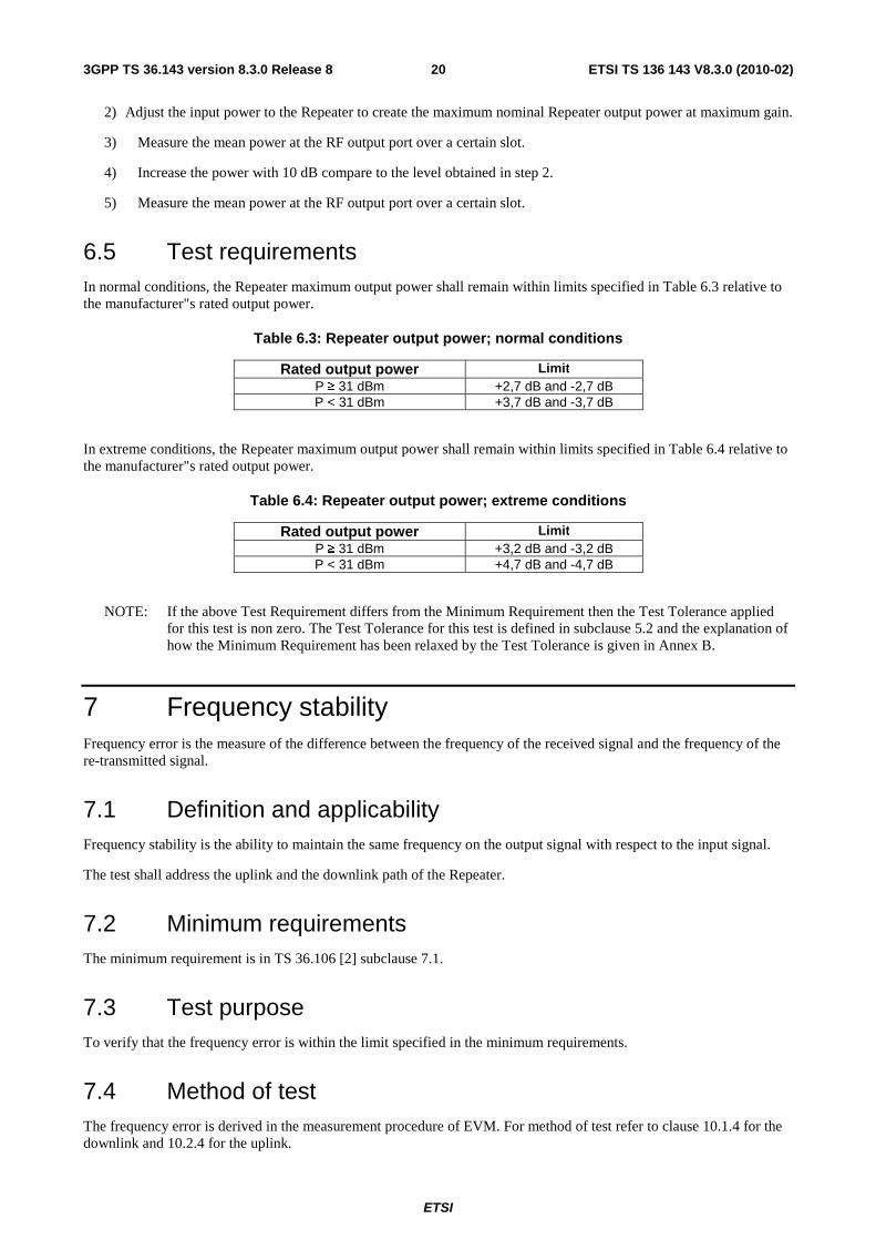
6.5 Test requirements In normal conditions, the Repeater maximum output power shall remain within limits specified in Table 6.3 relative to the manufacturer"s rated output power.
Table 6.3: Repeater output power; normal conditions
Rated output power Limit P ≥ 31 dBm +2,7 dB and -2,7 dB P < 31 dBm +3,7 dB and -3,7 dB
In extreme conditions, the Repeater maximum output power shall remain within limits specified in Table 6.4 relative to the manufacturer"s rated output power.
Table 6.4: Repeater output power; extreme conditions
Rated output power Limit P ≥ 31 dBm +3,2 dB and -3,2 dB P < 31 dBm +4,7 dB and -4,7 dB
NOTE: If the above Test Requirement differs from the Minimum Requirement then the Test Tolerance applied for this test is non zero. The Test Tolerance for this test is defined in subclause 5.2 and the explanation of how the Minimum Requirement has been relaxed by the Test Tolerance is given in Annex B.
7 Frequency stability Frequency error is the measure of the difference between the frequency of the received signal and the frequency of the re-transmitted signal.
7.1 Definition and applicability Frequency stability is the ability to maintain the same frequency on the output signal with respect to the input signal.
The test shall address the uplink and the downlink path of the Repeater.
7.2 Minimum requirements The minimum requirement is in TS 36.106 [2] subclause 7.1.
7.3 Test purpose To verify that the frequency error is within the limit specified in the minimum requirements.
7.4 Method of test The frequency error is derived in the measurement procedure of EVM. For method of test refer to clause 10.1.4 for the downlink and 10.2.4 for the uplink.

ETSI
ETSI TS 136 143 V8.3.0 (2010-02)213GPP TS 36.143 version 8.3.0 Release 8
7.5 Test requirement The measurement result of 7.4 shall not exceed:
| f IN – f out | ≤ (f out * 0,01) + 12 Hz
8 Out of band gain
8.1 Definition and applicability Out of band gain refers to the gain of the Repeater immediately outside the pass band. The measurements shall apply to both paths uplink and downlink of the Repeater.
8.2 Minimum requirements The minimum requirement is in TS 36.106 [2] subclause 8.1.
8.3 Test purpose The purpose of this test is to verify that the Repeater meets the out of band gain requirements as specified by the minimum requirements.
8.4 Method of test
8.4.1 Initial conditions
Test environment: normal; see Annex A2
A measurement system set-up is shown in annex C.
1) f_offset_CW is the offset between the outer channel edge frequency of the outer channel in the pass band and a CW-signal.
2) The test shall be performed with an f_offset_CW of 0.2 MHz, 0.5 MHz, 1 MHz, 5 MHz, 7,5 MHz, 10 MHz, 12,5 MHz, 15 MHz and 20 MHz, excluding other pass bands. In addition the test shall also be performed for all harmonic frequencies of the repeaters pass band up to 12,75 GHz.
8.4.2 Procedure
1) Set the Repeater to maximum gain.
2) Set the signal generator to generate a CW-signal, applied to the input port of the Repeater. The power level of the RF input signal shall be at least 5 dB below the power level which, when applied within the pass band, would produce the maximum rated output power, as declared by the manufacturer. This is to ensure that the equipment is operating in the linear output range.
3) The average output power in each case shall be measured using a spectrum analyser connected to the output port of the Repeater and the net gain shall be recorded and compared to table 8.5-1 or table 8.5-2 whichever is lower.
4) With the same input power as in step 1) set the repeater gain to the minimum specified by the manufacturer.
5) The average output power in each case shall be measured using a spectrum analyser connected to the output port of the repeater and the net gain shall be recorded and compared to table 8.5-1 or table 8.5-2 whichever is lower.

ETSI
ETSI TS 136 143 V8.3.0 (2010-02)223GPP TS 36.143 version 8.3.0 Release 8
8.5 Test requirements
Table 8.5-1: Out of band gain limits 1
Frequency offset, f_offset_CW Maximum gain 0,2 ≤ f_offset_CW < 1 MHz 60,5 dB 1 ≤ f_offset_CW < 5 MHz 45,5 dB
5 ≤ f_offset_CW < 10 MHz 45,5 dB 10 MHz ≤ f_offset_CW 35,5 dB
Table 8.5-2: Out of band gain limits 2
Frequency offset, f_offset_CW Maximum gain 10 MHz ≤ f_offset_CW Out of band gain ≤ minimum donor coupling loss + 0,5 dB
9 Unwanted emissions Unwanted emissions consist of out-of-band emissions and spurious emissions [4]. Out of band emissions are unwanted emissions immediately outside the pass band bandwidth resulting from the modulation process and non-linearity in the transmitter, but excluding spurious emissions. Spurious emissions are emissions which are caused by unwanted transmitter effects such as harmonics emission, parasitic emission, intermodulation products and frequency conversion products, but exclude out of band emissions.
The out-of-band emissions requirement for repeater is specified both in terms operating band unwanted emissions and protection of the BS receiver in the uplink operating band. The Operating band unwanted emissions define all unwanted emissions in the repeater operating band plus the frequency ranges 10 MHz above and 10 MHz below that band. Unwanted emissions outside of this frequency range are limited by a spurious emissions requirement.
9.1 Operating band unwanted emissions
9.1.1 Definition and applicability
The Operating band unwanted emission limits are defined from 10 MHz below the lowest frequency of the repeater operating band up to 10 MHz above the highest frequency of the repeater operating band.
The unwanted emission limits in the part of the operating band that falls in the spurious domain are consistent with ITU-R Recommendation SM.329 [5].
The requirements shall apply whatever the type of repeater considered (one or several pass bands). It applies for all configurations foreseen by the manufacturer"s specification.
The requirements of either subclause 9.1.5.1 (Category A limits) or subclause 9.1.5.2 (Category B limits) shall apply. The application of either Category A or Category B limits shall be the same as for spurious emissions (Mandatory Requirements) in subclause 9.2.5.
For Category B Operating band unwanted emissions, there are two options for the limits that may be applied regionally. Either the limits in subclause 9.1.5.2.1 or subclause 9.1.5.2.2 shall be applied.
9.1.2 Minimum requirements
The minimum requirements are in TS 36.106 [2] sub-clause 9.1.

ETSI
ETSI TS 136 143 V8.3.0 (2010-02)233GPP TS 36.143 version 8.3.0 Release 8
9.1.3 Test purpose
This test measures the operating band unwanted emission from the Repeater transmitter antenna connector, while the Repeater is in operation with, and without signal.
9.1.4 Method of test
9.1.4.1 Initial conditions
Test environment: normal; see Annex A2.
A measurement system set-up is shown in annex C.
1) Connect a signal generator to the input port of the Repeater.
2) Detection mode: True RMS.
9.1.4.2 Procedures
1) Set the Repeater to maximum gain.
2) Set the signal generator to generate signal(s) in accordance to table 9.1.4.2-1
Table 9.1.4.2-1: Stimulus signal for operating band unwanted emissions testing
Repeater under test link and passband bandwidth
Stimulus reference Note
Downlink pass band BW < 2.8 MHz
Repeater stimulus signal 4 The signal is defined in Annex D.4
Uplink pass band BW < 2.8 MHz
Repeater stimulus signal 3 The signal is defined in Annex D.3
Downlink pass band BW ≥ 2.8 MHz
Repeater stimulus signal 2 The signal is defined in Annex D.2
Uplink pass band BW ≥ 2.8 MHz
Repeater stimulus signal 1 The signal is defined in Annex D.1
at centre frequencies such that the whole signal can be fitted inside the repeater pass band and at level(s) which produce the manufacturer specified maximum output power at maximum gain.
3) The detecting device shall be configured with a measurement bandwidth as stated in the test requirement tables.
4) Measure the emission at the specified frequencies with specified measurement bandwidth and note that the measured value does not exceed the specified value. To select the table and the maximum level, use the repeater pass band and stimulus signal if necessary.
5) Increase the input power with 10 dB compared to the level obtained in step 2.
6) Measure the emission at the specified frequencies with specified measurement bandwidth and note that the measured value does not exceed the specified value. To select the table and the maximum level, use the repeater pass band and stimulus signal if necessary.
7) If the pass band is wider than 2,8 MHz, repeat step 1) to 6) with a new stimulus signal of the same kind, but using different centre frequencies such that the whole signal fitted in the repeater pass band.
8) Switch off the input signal to the repeater.
9) Measure the emission at the specified frequencies with specified measurement bandwidth and note that the measured value does not exceed the specified value. To select the table and the maximum level, use the repeater pass band.

ETSI
ETSI TS 136 143 V8.3.0 (2010-02)243GPP TS 36.143 version 8.3.0 Release 8
NOTE: As a general rule the resolution bandwidth of the measuring equipment should be equal to the measurement bandwidth. However, to improve measurement accuracy, sensitivity and efficiency, the resolution bandwidth may be smaller than the measurement bandwidth. When the resolution bandwidth is smaller than the measurement bandwidth, the result should be integrated over the measurement bandwidth in order to obtain the equivalent noise bandwidth of the measurement bandwidth.
9.1.5 Test requirements
Emissions shall not exceed the maximum levels specified in the tables below, where:
- Δf is the separation between the nominal pass band edge frequency and the nominal -3dB point of the measuring filter closest to the carrier frequency.
- Nominal passband edge is the lowest and highest frequency of the pass band of the repeater.
- BWMeas is the measurement bandwidth.
- BWPass band is the bandwidth of the repeaters pass band.
- f_offset is the separation between the nominal pass band edge frequency and the centre of the measuring filter.
- f_offsetmax is the offset to the frequency 10 MHz outside the repeater operating band.
- Δfmax is equal to f_offsetmax minus half of the bandwidth of the measuring filter.
The requirements of either subclause 9.1.5.1 or subclause 9.1.5.2 shall apply.
The Additional operating band unwanted emission limits defined in subclause 9.1.5.3 below may be mandatory in certain regions. In other regions it may not apply.
The requirements of subclause 9.1.5.4 shall apply.
Unless otherwise stated, all requirements are measured as mean power (RMS).
9.1.5.1 Operating band unwanted emission (Category A)
For E-UTRA FDD repeater operating in Bands 5, 6, 8, 12, 13, 14 and 17 emissions shall not exceed the maximum levels specified in Tables 9.1.5.1-1 and 9.1.5.1-2. The measurements shall apply to both paths uplink and downlink of the Repeater.
Table 9.1.5.1-1: General operating band unwanted emission limits for repeater pass band bandwidth lower than 5 MHz (E-UTRA bands <1GHz) for Category A
Frequency offset of measurement filter -3dB point,
Δf
Frequency offset of measurement filter centre frequency,
f_offset
Test requirement Measure-ment
bandwidth
0 MHz ≤ Δf < BWPass band
BWMeas/2 ≤ f_offset < BWPass band + BWMeas/2
[ ]dBBWBWMax PassbandPassband 75.025,1;0625.21875.2 −∗−+∗− +
[ ]dBmeas
BWoffsetf
BW
BWMax
Passband
Passband
⎟⎟
⎠
⎞
⎜⎜
⎝
⎛−−−
2_*
12;10
+ 1,5 dB
100 kHz
BWPass band≤ Δf < 2*BWPass band
BWPass band + BWMeas/2 ≤ f_offset <
2* BWPass band + BWMeas/2
[ ]dBmBWBWMax PassbandPassband 73.1145.0;0.943.1 −∗−−∗−
+ 1,5 dB
100 kHz
2*BWPass band ≤ Δf ≤ Δfmax
2* BWPass band + BWMeas/2 ≤ f_offset <
f_offsetmax
-13 dBm 100 kHz
Note: Frequencies and bandwidth are given in MHz
ETSI
ETSI TS 136 143 V8.3.0 (2010-02)253GPP TS 36.143 version 8.3.0 Release 8
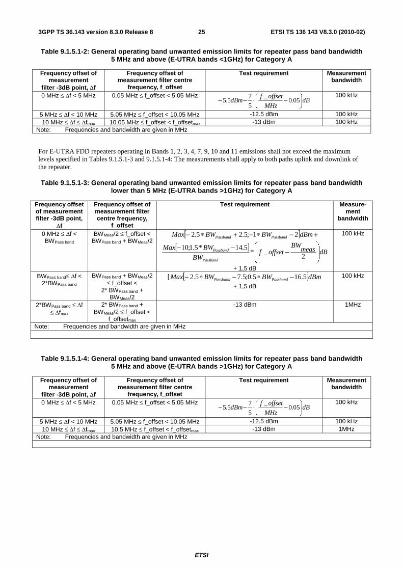
Table 9.1.5.1-2: General operating band unwanted emission limits for repeater pass band bandwidth 5 MHz and above (E-UTRA bands <1GHz) for Category A
Frequency offset of measurement
filter -3dB point, Δf
Frequency offset of measurement filter centre
frequency, f_offset
Test requirement Measurement bandwidth
0 MHz ≤ Δf < 5 MHz 0.05 MHz ≤ f_offset < 5.05 MHz dB
MHz
offsetfdBm ⎟
⎠
⎞⎜⎝
⎛ −⋅−− 05.0_
5
75.5 100 kHz
5 MHz ≤ Δf < 10 MHz 5.05 MHz ≤ f_offset < 10.05 MHz -12.5 dBm 100 kHz 10 MHz ≤ Δf ≤ Δfmax 10.05 MHz ≤ f_offset < f_offsetmax -13 dBm 100 kHz
Note: Frequencies and bandwidth are given in MHz
For E-UTRA FDD repeaters operating in Bands 1, 2, 3, 4, 7, 9, 10 and 11 emissions shall not exceed the maximum levels specified in Tables 9.1.5.1-3 and 9.1.5.1-4: The measurements shall apply to both paths uplink and downlink of the repeater.
Table 9.1.5.1-3: General operating band unwanted emission limits for repeater pass band bandwidth lower than 5 MHz (E-UTRA bands >1GHz) for Category A
Frequency offset of measurement filter -3dB point,
Δf
Frequency offset of measurement filter centre frequency,
f_offset
Test requirement Measure-ment
bandwidth
0 MHz ≤ Δf < BWPass band
BWMeas/2 ≤ f_offset < BWPass band + BWMeas/2
[ ] +−∗−+∗− dBmBWBWMax PassbandPassband 21;5.25.2
[ ]dBmeas
BWoffsetf
BW
BWMax
Passband
Passband
⎟⎟
⎠
⎞
⎜⎜
⎝
⎛−−−
2_*
5.14*5.1;10
+ 1,5 dB
100 kHz
BWPass band≤ Δf < 2*BWPass band
BWPass band + BWMeas/2 ≤ f_offset <
2* BWPass band + BWMeas/2
[ [ ]dBmBWBWMax PassbandPassband 5.165.0;5.75.2 −∗−∗−
+ 1,5 dB
100 kHz
2*BWPass band ≤ Δf ≤ Δfmax
2* BWPass band + BWMeas/2 ≤ f_offset <
f_offsetmax
-13 dBm 1MHz
Note: Frequencies and bandwidth are given in MHz
Table 9.1.5.1-4: General operating band unwanted emission limits for repeater pass band bandwidth 5 MHz and above (E-UTRA bands >1GHz) for Category A
Frequency offset of measurement
filter -3dB point, Δf
Frequency offset of measurement filter centre
frequency, f_offset
Test requirement Measurement bandwidth
0 MHz ≤ Δf < 5 MHz 0.05 MHz ≤ f_offset < 5.05 MHz dB
MHz
offsetfdBm ⎟
⎠
⎞⎜⎝
⎛ −⋅−− 05.0_
5
75.5 100 kHz
5 MHz ≤ Δf < 10 MHz 5.05 MHz ≤ f_offset < 10.05 MHz -12.5 dBm 100 kHz 10 MHz ≤ Δf ≤ Δfmax 10.5 MHz ≤ f_offset < f_offsetmax -13 dBm 1MHz
Note: Frequencies and bandwidth are given in MHz

ETSI
ETSI TS 136 143 V8.3.0 (2010-02)263GPP TS 36.143 version 8.3.0 Release 8
9.1.5.2 Operating band unwanted emissions (Category B)
For Category B operating band unwanted emissions, there are two options for the limits that may be applied regionally. Either the limits in subclause 9.1.5.2.1 or subclause 9.1.5.2.2 shall be applied. The measurements shall apply to both paths uplink and downlink of the Repeater.
9.1.5.2.1 Category B test requirements (Option 1)
For E-UTRA FDD repeater operating in Bands 5, 6, 8, 12, 13, 14 and 17 emissions shall not exceed the maximum levels specified in Tables 9.1.5.2.1-1 and 9.1.5.2.1-2:
Table 9.1.5.2.1-1: General operating band unwanted emission limits for repeater pass band bandwidth lower than 5 MHz (E-UTRA bands <1GHz) for Category B
Frequency offset of measurement filter -3dB point,
Δf
Frequency offset of measurement filter centre frequency,
f_offset
Test requirement Measure-ment
bandwidth
0 MHz ≤ Δf < BWPass band
BWMeas/2 ≤ f_offset < BWPass band + BWMeas/2
[ [ ] +−∗−+∗− dBmBWBWMax PassbandPassband 21;5.25.2
[ ]dBmeas
BWoffsetf
BW
BWMax
Passband
Passband
⎟⎟
⎠
⎞
⎜⎜
⎝
⎛−−−
2_*
5.14*5.1;10
+ 1,5 dB
100 kHz
BWPass band≤ Δf < 2*BWPass band
BWPass band + BWMeas/2 ≤ f_offset <
2* BWPass band + BWMeas/2
[ ]dBmBWBWMax PassbandPassband 5.165.0;5.75.2 −∗−∗− + 1,5
dB
100 kHz
2*BWPass band ≤ Δf ≤ Δfmax
2* BWPass band + BWMeas/2 ≤ f_offset <
f_offsetmax
-16 dBm 100 kHz
NOTE 1: Frequencies and bandwidth are given in MHz. NOTE 2: If the repeater input signal consists of E-UTRA signals with a channel bandwidth of 1.4 MHz placed so that the
channel edge is less than 200 kHz from the pass band edge, the requirements in Table 9.1.5.2.1-3 superseeds Table 9.1.5.2.1-1 and Table 9.1.5.2.1-2 for applicable frequency offsets.
NOTE 3: If the repeater input signal consists of E-UTRA signals with a channel bandwidth of 3 MHz placed so that the channel edge is less than 200 kHz from the pass band edge, the requirements in Table 9.1.5.2.1-4 superseeds Table 9.1.5.2.1-1 and Table 9.1.5.2.1-2 for applicable frequency offsets.

ETSI
ETSI TS 136 143 V8.3.0 (2010-02)273GPP TS 36.143 version 8.3.0 Release 8
Table 9.1.5.2.1-2: General operating band unwanted emission limits for repeater pass band bandwidth 5 MHz and above (E-UTRA bands <1GHz) for Category B
Frequency offset of measurement
filter -3dB point, Δf
Frequency offset of measurement filter centre
frequency, f_offset
Test requirement Measurement bandwidth
(Note 1) 0 MHz ≤ Δf < 5 MHz 0.05 MHz ≤ f_offset < 5.05 MHz
dBMHz
offsetfdBm ⎟
⎠
⎞⎜⎝
⎛ −⋅−− 05.0_
5
75.5 100 kHz
5 MHz ≤ Δf < 10 MHz 5.05 MHz ≤ f_offset < 10.05 MHz -12.5 dBm 100 kHz 10 MHz ≤ Δf ≤ Δfmax 10.05 MHz ≤ f_offset < f_offsetmax -16 dBm 100 kHz
NOTE 1: Frequencies and bandwidth are given in MHz. NOTE 2: If the repeater input signal consists of E-UTRA signals with a channel bandwidth of 1.4 MHz placed so that the
channel edge is less than 200 kHz from the pass band edge, the requirements in Table 9.1.5.2.1-3 superseeds Table 9.1.5.2.1-1 and Table 9.1.5.2.1-2 for applicable frequency offsets.
NOTE 3: If the repeater input signal consists of E-UTRA signals with a channel bandwidth of 3 MHz placed so that the channel edge is less than 200 kHz from the pass band edge, the requirements in Table 9.1.5.2.1-4 superseeds Table 9.1.5.2.1-1 and Table 9.1.5.2.1-2 for applicable frequency offsets.
Table 9.1.5.2.1-3: Conditional operating band unwanted emission limits for repeater input signal bandwidth of 1.4 MHz
Frequency offset of measurement
filter -3dB point, Δf
Frequency offset of measurement filter centre
frequency, f_offset
Test requirement Measurement bandwidth
0 MHz ≤ Δf < 1.05 MHz 0.05 MHz ≤ f_offset < 1.1 MHz dBMHz
offsetfdBm ⎟
⎠
⎞⎜⎝
⎛ −⋅−+ 05.0_
4.1
100.5 100 kHz
Note: Frequencies and bandwidth are given in MHz
Table 9.1.5.2.1-4: Conditional operating band unwanted emission limits for repeater input signal bandwidth of 3 MHz
Frequency offset of measurement
filter -3dB point, Δf
Frequency offset of measurement filter centre
frequency, f_offset
Test requirement Measurement bandwidth
0 MHz ≤ Δf < 1.05 MHz 0.05 MHz ≤ f_offset < 1.1 MHz dBMHz
offsetfdBm ⎟
⎠
⎞⎜⎝
⎛ −⋅−− 05.0_
3
103.5 100 kHz
Note: Frequencies and bandwidth are given in MHz
For E-UTRA FDD repeater operating in Bands 1, 2, 3, 4, 7, 9, 10 and 11 emissions shall not exceed the maximum levels specified in Tables 9.1.5.2.1-5 and 9.1.5.2.1-6: The measurements shall apply to both paths uplink and downlink of the Repeater.

ETSI
ETSI TS 136 143 V8.3.0 (2010-02)283GPP TS 36.143 version 8.3.0 Release 8
Table 9.1.5.2.1-5: General operating band unwanted emission limits for repeater pass band bandwidth lower than 5 MHz (E-UTRA bands >1GHz) for Category B
Frequency offset of measurement filter -3dB point,
Δf
Frequency offset of measurement filter centre frequency,
f_offset
Test requirement Measure-ment
bandwidth
0 MHz ≤ Δf < BWPass band
BWMeas/2 ≤ f_offset < BWPass band + BWMeas/2
[ ] +−∗−+∗− dBmBWBWMax PassbandPassband 21;5.25.2
[ ]dBmeas
BWoffsetf
BWBWMax
Passband
Passband
⎟⎟
⎠
⎞
⎜⎜
⎝
⎛−−−
2_*
5.14*5.1;10
+ 1,5 dB
100 kHz
BWPass band≤ Δf < 2*BWPass band
BWPass band + BWMeas/2 ≤ f_offset <
2* BWPass band + BWMeas/2
[ ]dBmBWBWMax PassbandPassband 5.165.0;5.75.2 −∗−∗−
+ 1,5 dB
100 kHz
2*BWPass band ≤ Δf ≤ Δfmax
2* BWPass band + BWMeas/2 ≤ f_offset <
f_offsetmax
-15 dBm 1MHz
NOTE 1: Frequencies and bandwidth are given in MHz. NOTE 2: If the repeater input signal consists of E-UTRA signals with a channel bandwidth of 1.4 MHz placed so that the
channel edge is less than 200 kHz from the pass band edge, the requirements in Table 9.1.5.2.1-7 superseeds Table 9.1.5.2.1-5 and Table 9.1.5.2.1-6 for applicable frequency offsets.
NOTE 3: If the repeater input signal consists of E-UTRA signals with a channel bandwidth of 3 MHz placed so that the channel edge is less than 200 kHz from the pass band edge, the requirements in Table 9.1.5.2.1-8 superseeds Table 9.1.5.2.1-5 and Table 9.1.5.2.1-6 for applicable frequency offsets.
Table 9.1.5.2.1-6: General operating band unwanted emission limits for repeater pass band bandwidth 5 MHz and above (E-UTRA bands >1GHz) for Category B
Frequency offset of measurement
filter -3dB point, Δf
Frequency offset of measurement filter centre
frequency, f_offset
Test requirement Measurement bandwidth
0 MHz ≤ Δf < 5 MHz 0.05 MHz ≤ f_offset < 5.05 MHz dB
MHz
offsetfdBm ⎟
⎠
⎞⎜⎝
⎛ −⋅−− 05.0_
5
75.5 100 kHz
5 MHz ≤ Δf < 10 MHz 5.05 MHz ≤ f_offset < 10.05 MHz -12.5 dBm 100 kHz 10 MHz ≤ Δf ≤ Δfmax 10.5 MHz ≤ f_offset < f_offsetmax -15 dBm 1MHz
NOTE 1: Frequencies and bandwidth are given in MHz. NOTE 2: If the repeater input signal consists of E-UTRA signals with a channel bandwidth of 1.4 MHz placed so that the
channel edge is less than 200 kHz from the pass band edge, the requirements in Table 9.1.5.2.1-7 superseeds Table 9.1.5.2.1-5 and Table 9.1.5.2.1-6 for applicable frequency offsets.
NOTE 3: If the repeater input signal consists of E-UTRA signals with a channel bandwidth of 3 MHz placed so that the channel edge is less than 200 kHz from the pass band edge, the requirements in Table 9.1.5.2.1-8 superseeds Table 9.1.5.2.1-5 and Table 9.1.5.2.1-6 for applicable frequency offsets.
Table 9.1.5.2.1-7: Conditional operating band unwanted emission limits for repeater input signal bandwidth of 1.4 MHz
Frequency offset of measurement
filter -3dB point, Δf
Frequency offset of measurement filter centre
frequency, f_offset
Test requirement Measurement bandwidth
0 MHz ≤ Δf < 1.05 MHz 0.05 MHz ≤ f_offset < 1.1 MHz dBMHz
offsetfdBm ⎟
⎠
⎞⎜⎝
⎛ −⋅−+ 05.0_
4.1
100.5 100 kHz
Note: Frequencies and bandwidth are given in MHz
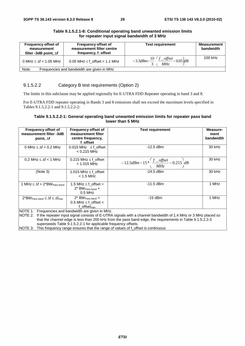
ETSI
ETSI TS 136 143 V8.3.0 (2010-02)293GPP TS 36.143 version 8.3.0 Release 8
Table 9.1.5.2.1-8: Conditional operating band unwanted emission limits for repeater input signal bandwidth of 3 MHz
Frequency offset of measurement
filter -3dB point, Δf
Frequency offset of measurement filter centre
frequency, f_offset
Test requirement Measurement bandwidth
0 MHz ≤ Δf < 1.05 MHz 0.05 MHz ≤ f_offset < 1.1 MHz dBMHz
offsetfdBm ⎟
⎠
⎞⎜⎝
⎛ −⋅−− 05.0_
3
103.5 100 kHz
Note: Frequencies and bandwidth are given in MHz
9.1.5.2.2 Category B test requirements (Option 2)
The limits in this subclause may be applied regionally for E-UTRA FDD Repeater operating in band 3 and 8.
For E-UTRA FDD repeater operating in Bands 3 and 8 emissions shall not exceed the maximum levels specified in Tables 9.1.5.2.2-1 and 9.1.5.2.2-2:
Table 9.1.5.2.2-1: General operating band unwanted emission limits for repeater pass band lower than 5 MHz
Frequency offset of measurement filter -3dB
point, Δf
Frequency offset of measurement filter centre frequency,
f_offset
Test requirement Measure-ment
bandwidth
0 MHz ≤ Δf < 0.2 MHz 0.015 MHz ≤ f_offset < 0.215 MHz
-12.5 dBm 30 kHz
0.2 MHz ≤ Δf < 1 MHz 0.215 MHz ≤ f_offset < 1.015 MHz dB
MHz
offsetfdBm ⎟
⎠
⎞⎜⎝
⎛ −−− 215.0_
*155.12 30 kHz
(Note 3) 1.015 MHz ≤ f_offset < 1.5 MHz
-24.5 dBm 30 kHz
1 MHz ≤ Δf < 2*BWPass band 1.5 MHz ≤ f_offset < 2* BWPass band +
0.5 MHz
-11.5 dBm 1 MHz
2*BWPass band ≤ Δf ≤ Δfmax 2* BWPass band + 0.5 MHz ≤ f_offset <
f_offsetmax
-15 dBm 1 MHz
NOTE 1: Frequencies and bandwidth are given in MHz. NOTE 2: If the repeater input signal consists of E-UTRA signals with a channel bandwidth of 1.4 MHz or 3 MHz placed so
that the channel edge is less than 200 kHz from the pass band edge, the requirements in Table 9.1.5.2.2-3 superseeds Table 9.1.5.2.2-1 for applicable frequency offsets.
NOTE 3: This frequency range ensures that the range of values of f_offset is continuous

ETSI
ETSI TS 136 143 V8.3.0 (2010-02)303GPP TS 36.143 version 8.3.0 Release 8
Table 9.1.5.2.2-2: General operating band unwanted emission limits for repeater pass band 5 MHz and above
Frequency offset of measurement filter -3dB
point, Δf
Frequency offset of measurement filter centre frequency,
f_offset
Test requirement Measure-ment
bandwidth
0 MHz ≤ Δf < 0.2 MHz 0.015 MHz ≤ f_offset < 0.215 MHz
-12.5 dBm 30 kHz
0.2 MHz ≤ Δf < 1 MHz 0.215 MHz ≤ f_offset < 1.015 MHz dB
MHz
offsetfdBm ⎟
⎠
⎞⎜⎝
⎛ −−− 215.0_
*155.12 30 kHz
(Note 3) 1.015 MHz ≤ f_offset < 1.5 MHz
-24.5 dBm 30 kHz
1 MHz ≤ Δf < 10 MHz 1.5 MHz ≤ f_offset < 10.5 MHz
-11.5 dBm 1 MHz
10 MHz ≤ Δf ≤ Δfmax 10.5 MHz ≤ f_offset < f_offsetmax
-15 dBm 1 MHz
NOTE 1: Frequencies and bandwidth are given in MHz. NOTE 2: If the repeater input signal consists of E-UTRA signals with a channel bandwidth of 1.4 MHz or 3 MHz placed so
that the channel edge is less than 200 kHz from the pass band edge, the requirements in Table 9.1.5.2.2-3 superseeds Table 9.1.5.2.2-2 for applicable frequency offsets.
NOTE 3: This frequency range ensures that the range of values of f_offset is continuous
Table 9.1.5.2.2-3: Conditional operating band unwanted emission limits
Frequency offset of measurement filter -3 dB
point, Δf
Frequency offset of measurement filter centre frequency,
f_offset
Test requirement Measurement bandwidth
0 MHz ≤ Δf < 0.05 MHz 0.015 MHz ≤ f_offset < 0.065 MHz dB
MHz
offsetfdBm ⎟
⎠
⎞⎜⎝
⎛ −⋅− 015.0_
605.6 30 kHz
0.05 MHz ≤ Δf < 0.15 MHz 0.065 MHz ≤ f_offset < 0.165 MHz dB
MHz
offsetfdBm ⎟
⎠
⎞⎜⎝
⎛ −⋅− 065.0_
1605.3 30 kHz
0.15 MHz ≤ Δf < 0.2 MHz 0.165 MHz ≤ f_offset < 0.215 MHz
-12.5 dBm 30 kHz
NOTE: Frequencies and bandwidth are given in MHz.
9.1.5.3 Additional requirements
In certain regions the following requirement may apply. For E-UTRA FDD repeaters operating in Band 5, emissions shall not exceed the maximum levels specified in Table 9.1.5.3-1. The measurements shall apply to both paths uplink and downlink of the Repeater.
Table 9.1.5.3-1: Additional operating band unwanted emission limits for E-UTRA bands <1GHz
Input signal
bandwidth
Frequency offset of measurement
filter -3dB point, Δf
Frequency offset of measurement filter centre
frequency, f_offset
Test requirement
Measurement bandwidth
(Note 1) 1.4 MHz 0 MHz ≤ Δf < 1 MHz 0.005 MHz ≤ f_offset < 0.995 MHz -14 dBm 10 kHz 3 MHz 0 MHz ≤ Δf < 1 MHz 0.015 MHz ≤ f_offset < 0.985 MHz -13 dBm 30 kHz 5 MHz 0 MHz ≤ Δf < 1 MHz 0.015 MHz ≤ f_offset < 0.985 MHz -15 dBm 30 kHz 10 MHz 0 MHz ≤ Δf < 1 MHz 0.05 MHz ≤ f_offset < 0.95 MHz -13 dBm 100 kHz 15 MHz 0 MHz ≤ Δf < 1 MHz 0.05 MHz ≤ f_offset < 0.95 MHz -13 dBm 100 kHz 20 MHz 0 MHz ≤ Δf < 1 MHz 0.05 MHz ≤ f_offset < 0.95 MHz -13 dBm 100 kHz
All 1 MHz ≤ Δf < Δfmax 1.05 MHz ≤ f_offset < f_offsetmax -13 dBm 100 kHz

ETSI
ETSI TS 136 143 V8.3.0 (2010-02)313GPP TS 36.143 version 8.3.0 Release 8
In certain regions the following requirement may apply. For E-UTRA FDD repeaters operating in Bands 2, 4, and 10 emissions shall not exceed the maximum levels specified in Table 9.1.5.3-2. The measurements shall apply to both paths uplink and downlink of the Repeater.
Table 9.1.5.3-2: Additional operating band unwanted emission limits for E-UTRA bands>1GHz
Input signal
bandwidth
Frequency offset of measurement
filter -3dB point, Δf
Frequency offset of measurement filter centre
frequency, f_offset
Test requirement
Measurement bandwidth
(Note 1) 1.4 MHz 0 MHz ≤ Δf < 1 MHz 0.005 MHz ≤ f_offset < 0.995 MHz -14 dBm 10 kHz 3 MHz 0 MHz ≤ Δf < 1 MHz 0.015 MHz ≤ f_offset < 0.985 MHz -13 dBm 30 kHz 5 MHz 0 MHz ≤ Δf < 1 MHz 0.015 MHz ≤ f_offset < 0.985 MHz -15 dBm 30 kHz 10 MHz 0 MHz ≤ Δf < 1 MHz 0.05 MHz ≤ f_offset < 0.95 MHz -13 dBm 100 kHz 15 MHz 0 MHz ≤ Δf < 1 MHz 0.05 MHz ≤ f_offset < 0.95 MHz -15 dBm 100 kHz 20 MHz 0 MHz ≤ Δf < 1 MHz 0.05 MHz ≤ f_offset < 0.95 MHz -16 dBm 100 kHz
All 1 MHz ≤ Δf < Δfmax 1.5 MHz ≤ f_offset < f_offsetmax -13 dBm 1 MHz
In certain regions the following requirement may apply. For E-UTRA FDD repeaters operating in Bands 12, 13, 14 and 17 emissions shall not exceed the maximum levels specified in Table 9.1.5.3-3. The measurements shall apply to both paths Uplink and Downlink of the Repeater.
Table 9.1.5.3-3: Additional operating band unwanted emission limits for E-UTRA (bands 12, 13, 14 and 17)
Input signal
bandwidth
Frequency offset of measurement
filter -3dB point, Δf
Frequency offset of measurement filter centre
frequency, f_offset
Test requirement
Measurement bandwidth
(Note 1) All 0 MHz ≤ Δf < 100 kHz 0.015 MHz ≤ f_offset < 0.085 MHz -13 dBm 30 kHz All 100 kHz ≤ Δf < Δfmax 150 kHz ≤ f_offset < f_offsetmax -13 dBm 100 kHz
NOTE : For signal bandwidths between the values given in Table"s 9.1.5.3-1 and 9.1.5.3-2, the requirements can be calculated by linearly interpolating between the requirements closest to the wanted signal bandwidth.
9.1.5.4 Protection of the BS receiver in the operating band
This requirement shall be applied for the protection of E-UTRA FDD BS receiver in geographic areas in which E-UTRA-FDD Repeater and E-UTRA-FDD BS are deployed.
The requirement applies to the uplink of the repeater, at maximum gain, at frequencies that are more than 10 MHz below or more than 10 MHz above the repeater pass band.
The power of any operating band unwanted emission shall not exceed the limits in Table 9.1.5.4-1.
Table 9.1.5.4-1: Uplink operating band unwanted emissions limits for protection of the BS receiver
Maximum Level
Measurement Bandwidth
Note
-53 dBm 100 kHz
NOTE 1: These requirements in Table 9.1.5.4-1: for the uplink direction of the Repeater reflect what can be achieved with present state of the art technology and are based on a coupling loss of 73 dB between a Repeater and an E-UTRA FDD BS receiver.
NOTE 2: The requirements shall be reconsidered when the state of the art technology progresses.
NOTE 3: The protection of GSM-R is for further study.

ETSI
ETSI TS 136 143 V8.3.0 (2010-02)323GPP TS 36.143 version 8.3.0 Release 8
9.2 Spurious emissions
9.2.1 Definition and applicability
The spurious emission limits apply from 9 kHz to 12.75 GHz, excluding the frequency range from 10 MHz below the lowest frequency of the repeaters operating band up to 10 MHz above the highest frequency of the repeaters operating band. Exceptions are the requirement in Table 9.2.5.3-2 and 9.2.5.3-3 that apply also closer than 10 MHz from repeaters operating band.
The requirements shall apply whatever the type of repeater considered (one or several pass bands). It applies for all configurations foreseen by the manufacturer"s specification. The measurements shall apply to both paths uplink and downlink of the Repeater.
Unless otherwise stated, all requirements are measured as mean power (RMS).
9.2.2 Minimum requirements
The minimum requirements are in TS 36.106 [2] sub-clause 9.2.
9.2.3 Test purpose
This test measures the conducted spurious emission from the Repeater transmitter antenna connector, while the Repeater is in operation with, and without signal.
9.2.4 Method of test
9.2.4.1 Initial conditions
Test environment: normal; see Annex A2.
A measurement system set-up is shown in annex C.
1) Connect a signal generator to the input port of the Repeater
2) Detection mode: True RMS.
9.2.4.2 Procedures
1) Set the Repeater to maximum gain.
2) Set the signal generator to generate signal(s) in accordance to table 9.2.4.2-1
Table 9.2.4.2-1: Stimulus signal for spurious emissions testing
Repeater under test link and passband bandwidth
Stimulus reference Note
Downlink pass band BW < 2.8 MHz
Repeater stimulus signal 4 The signal is defined in Annex D.4
Uplink pass band BW < 2.8 MHz
Repeater stimulus signal 3 The signal is defined in Annex D.3
Downlink pass band BW ≥ 2.8 MHz
Repeater stimulus signal 2 The signal is defined in Annex D.2
Uplink pass band BW ≥ 2.8 MHz
Repeater stimulus signal 1 The signal is defined in Annex D.1
at centre frequencies such that the whole signal can be fitted inside the repeater pass band and at level(s) which produce the manufacturer specified maximum output power at maximum gain.
3) The detecting device shall be configured with a measurement bandwidth as stated in the test requirement tables.

ETSI
ETSI TS 136 143 V8.3.0 (2010-02)333GPP TS 36.143 version 8.3.0 Release 8
4) Measure the emission at the specified frequencies with specified measurement bandwidth and note that the measured value does not exceed the specified value.
5) Increase the input power with 10 dB compared to the level obtained in step 2.
6) Measure the emission at the specified frequencies with specified measurement bandwidth and note that the measured value does not exceed the specified value.
7) If the pass band is wider than 2,8 MHz repeat step 1) to 6) with a new stimulus signal of the same kind, but using different centre frequencies such that the whole signal fitted in the repeater pass band.
8) Switch off the input signal to the repeater.
9) Measure the emission at the specified frequencies with specified measurement bandwidth and note that the measured value does not exceed the specified value.
9.2.5 Test requirements
9.2.5.1 Spurious emission (Category A)
The power of any spurious emission shall not exceed the limits in table 9.2.5.1-1 in cases where Category A limits for spurious emissions, as defined in ITU-R Recommendation SM.329 [4], are applied.
Table 9.2.5.1-1: Uplink and downlink: General spurious emissions limits, Category A
Frequency range Maximum level Measurement Bandwidth Notes
9kHz – 150kHz
-13 dBm
1 kHz Note 1 150kHz – 30MHz 10 kHz Note 1 30MHz – 1GHz 100 kHz Note 1
1GHz – 12,75 GHz 1 MHz Note 1, Note 2 NOTE 1: Bandwidth as in ITU-R SM.329 [4], s4.1 NOTE 2: Upper frequency as in ITU-R SM.329 [4], s2.5 table 1
9.2.5.2 Spurious emission (Category B)
The power of any spurious emission shall not exceed the limits in table 9.2.5.2-1 in cases where Category B limits for spurious emissions, as defined in ITU-R Recommendation SM.329 [4], are applied.
Table 9.2.5.2-1: Uplink and downlink: General spurious emissions limits, Category B
Frequency range Maximum Level
Measurement Bandwidth
Note
9 kHz ↔ 150 kHz -36 dBm 1 kHz Note 1 150 kHz ↔ 30 MHz -36 dBm 10 kHz Note 1 30 MHz ↔ 1 GHz -36 dBm 100 kHz Note 1
1 GHz ↔ 12.75 GHz -30 dBm 1 MHz Note1, Note 2 NOTE 1: Bandwidth as in ITU-R SM.329 [4] , s4.1 NOTE 2: Upper frequency as in ITU-R SM.329 [4] , s2.5 table 1
9.2.5.3 Co-existence with other systems in the same geographical area
These requirements may be applied for the protection of UE, MS and/or BS operating in other frequency bands in the same geographical area. The requirements may apply in geographic areas in which both E-UTRA-FDD Repeater and a system operating in another frequency band than the E-UTRA operating band are deployed.

ETSI
ETSI TS 136 143 V8.3.0 (2010-02)343GPP TS 36.143 version 8.3.0 Release 8
Unless otherwise stated this requirement applies to the uplink and downlink of the repeater, at maximum gain.
The following requirements may be applied for the protection of GSM900, DCS1800, PCS1900, GSM850, UTRA FDD/TDD and/or E-UTRA in geographic areas in which both PHS and E-UTRA are deployed.
The power of any spurious emission shall not exceed the limits of Table 9.2.5.3-1 for an E-UTRA Repeater where requirements for co-existence with the system listed in the first column apply.

ETSI
ETSI TS 136 143 V8.3.0 (2010-02)353GPP TS 36.143 version 8.3.0 Release 8
Table 9.2.5.3-1: Spurious emissions limits for E-UTRA-FDD repeater in geographic coverage area of systems operating in other frequency bands
System type operating in the
same geographical
area
Frequency range for co-existence
requirement
Maximum Level
Measurement Bandwidth
Note
GSM900
921 – 960 MHz -57 dBm 100 kHz This requirement does not apply to E-UTRA FDD Repeater operating in band 8.
876 – 915 MHz -61 dBm 100 kHz
This requirement does not apply to the uplink of E-UTRA FDD Repeater operating in band 8, since it is already covered by the requirement in sub-clause 9.1.4
DCS1800
1805 – 1880 MHz -47 dBm 100 kHz This requirement does not apply to E-UTRA FDD Repeater operating in band 3.
1710 – 1785 MHz -61 dBm 100 kHz
This requirement does not apply to the uplink of E-UTRA FDD Repeater operating in band 3, since it is already covered by the requirement in sub-clause 9.1.4.
PCS1900
1930 – 1990 MHz -47 dBm 100 kHz This requirement does not apply to E-UTRA FDD Repeater operating in band 2
1850 – 1910 MHz -61 dBm 100 kHz
This requirement does not apply to the uplink of E-UTRA FDD Repeater operating in band 2, since it is already covered by the requirement in sub-clause 9.1.4.
GSM850
869 – 894 MHz -57 dBm 100 kHz This requirement does not apply to E-UTRA FDD Repeater operating in band 5
824 – 849 MHz -61 dBm 100 kHz
This requirement does not apply to the uplink of E-UTRA FDD Repeater operating in band 5, since it is already covered by the requirement in sub-clause 9.1.4.
UTRA FDD Band I or
E-UTRA Band 1
2110 – 2170 MHz -52 dBm 1 MHz This requirement does not apply to E-UTRA FDD Repeater operating in band 1,
1920 – 1980 MHz -49 dBm 1 MHz
This requirement does not apply to the uplink of E-UTRA FDD Repeater operating in band 1, since it is already covered by the requirement in sub-clause 9.1.4.
UTRA FDD Band II or
E-UTRA Band 2
1930 – 1990 MHz -52 dBm 1 MHz This requirement does not apply to E-UTRA FDD Repeater operating in band 2.
1850 – 1910 MHz -49 dBm 1 MHz
This requirement does not apply to the uplink of E-UTRA FDD Repeater operating in band 2, since it is already covered by the requirement in sub-clause 9.1.4
UTRA FDD Band III or
E-UTRA Band 3
1805 – 1880 MHz -52 dBm 1 MHz This requirement does not apply to E-UTRA FDD Repeater operating in band 3.
1710 – 1785 MHz -49 dBm 1 MHz
This requirement does not apply to the uplink of E-UTRA FDD Repeater operating in band 3, since it is already covered by the requirement in sub-clause 9.1.4.
UTRA FDD Band IV or
E-UTRA Band 4
2110 – 2155 MHz -52 dBm 1 MHz This requirement does not apply to E-UTRA FDD Repeater operating in band 4
1710 – 1755 MHz -49 dBm 1 MHz
This requirement does not apply to the uplink of E-UTRA FDD Repeater operating in band 4, since it is already covered by the requirement in sub-clause 9.1.4.
UTRA FDD Band V or
E-UTRA Band 5
869 – 894 MHz -52 dBm 1 MHz This requirement does not apply to E-UTRA FDD Repeater operating in band 5
824 – 849 MHz -49 dBm 1 MHz
This requirement does not apply to the uplink of E-UTRA FDD Repeater operating in band 5, since it is already covered by the requirement in sub-clause 9.1.4.
UTRA FDD Band VI or
E-UTRA Band 6
860 – 895 MHz -52 dBm 1 MHz This requirement does not apply to E-UTRA FDD Repeater operating in band 6
815 – 850 MHz -49 dBm 1 MHz
This requirement does not apply to the uplink of E-UTRA FDD Repeater operating in band 6, since it is already covered by the requirement in sub-clause 9.1.4.

ETSI
ETSI TS 136 143 V8.3.0 (2010-02)363GPP TS 36.143 version 8.3.0 Release 8
UTRA FDD Band VII or
E-UTRA Band 7
2620 – 2690 MHz -52 dBm 1 MHz This requirement does not apply to E-UTRA FDD Repeater operating in band 7.
2500 – 2570 MHz -49 dBm 1 MHz
This requirement does not apply to the uplink of E-UTRA FDD Repeater operating in band 7, since it is already covered by the requirement in sub-clause 9.1.4.
UTRA FDD Band VIII or
E-UTRA Band 8
925 – 960 MHz -52 dBm 1 MHz This requirement does not apply to E-UTRA FDD Repeater operating in band 8.
880 – 915 MHz -49 dBm 1 MHz
This requirement does not apply to the uplink of E-UTRA FDD Repeater operating in band 8, since it is already covered by the requirement in sub-clause 9.1.4.
UTRA FDD Band IX or
E-UTRA Band 9
1844.9 – 1879.9 MHz -52 dBm 1 MHz
This requirement does not apply to E-UTRA FDD Repeater operating in band 9.
1749.9 – 1784.9 MHz -49 dBm 1 MHz
This requirement does not apply to the uplink of E-UTRA FDD Repeater operating in band 9, since it is already covered by the requirement in sub-clause 9.1.4.
UTRA FDD Band X or
E-UTRA Band 10
2110 – 2170 MHz -52 dBm 1 MHz This requirement does not apply to E-UTRA FDD Repeater operating in band 10
1710 – 1770 MHz -49 dBm 1 MHz
This requirement does not apply to the uplink of E-UTRA FDD Repeater operating in band 10, since it is already covered by the requirement in sub-clause 9.1.4.
UTRA FDD Band XI or
E-UTRA Band 11
1475.9 – 1500.9 MHz -52 dBm 1 MHz This requirement does not apply to E-UTRA FDD
Repeater operating in band 11
1427.9 – 1452.9 MHz -49 dBm 1 MHz
This requirement does not apply to the uplink of E-UTRA FDD Repeater operating in band 11, since it is already covered by the requirement in sub-clause 9.1.4.
UTRA FDD Band XII or
E-UTRA Band 12
728 – 746 MHz -52 dBm 1 MHz This requirement does not apply to E-UTRA FDD Repeater operating in band 12.
698 – 716 MHz -49 dBm 1 MHz
This requirement does not apply to the uplink of E-UTRA FDD Repeater operating in band 12, since it is already covered by the requirement in sub-clause 9.1.4.
UTRA FDD Band XIII or
E-UTRA Band 13
746 – 756 MHz -52 dBm 1 MHz This requirement does not apply to E-UTRA FDD Repeater operating in band 13.
777 – 787 MHz -49 dBm 1 MHz
This requirement does not apply to the uplink of E-UTRA FDD Repeater operating in band 13, since it is already covered by the requirement in sub-clause 9.1.4.
UTRA FDD Band XIV or
E-UTRA Band 14
758 – 768 MHz -52 dBm 1 MHz This requirement does not apply to E-UTRA FDD Repeater operating in band 14.
788 – 798 MHz -49 dBm 1 MHz
This requirement does not apply to the uplink of E-UTRA FDD Repeater operating in band 14, since it is already covered by the requirement in sub-clause 9.1.4.
E-UTRA Band 17
734 – 746 MHz -52 dBm 1 MHz This requirement does not apply to E-UTRA FDD Repeater operating in band 17.
704 - 716 MHz -49 dBm 1 MHz
This requirement does not apply to the uplink of E-UTRA FDD Repeater operating in band 17, since it is already covered by the requirement in sub-clause 9.1.4.
UTRA TDD in Band a) or
E-UTRA Band 33 1900 – 1920 MHz
-52 dBm 1 MHz This requirement does not apply to the uplink of E-UTRA FDD Repeater operating in band 1.
-53 dBm 100 kHz This requirement is applied only to the uplink of E-UTRA FDD Repeater operating in band 1.
UTRA TDD in Band a) or
E-UTRA Band 34 2010 – 2025 MHz -52 dBm 1 MHz
UTRA TDD in Band b) or
E-UTRA Band 35 1850 – 1910 MHz
-52 dBm 1 MHz This requirement does not apply to the uplink of E-UTRA FDD Repeater operating in band 2.
-53 dBm 100 kHz This requirement is applied only to the uplink of E-UTRA FDD Repeater operating in band 2.

ETSI
ETSI TS 136 143 V8.3.0 (2010-02)373GPP TS 36.143 version 8.3.0 Release 8
UTRA TDD in Band b) or
E-UTRA Band 36 1930 – 1990 MHz -52 dBm 1 MHz
This requirement does not apply to the downlink of E-UTRA FDD Repeater operating in band 2.
UTRA TDD in Band c) or
E-UTRA Band 37 1910 – 1930 MHz
-52 dBm 1 MHz
This requirement does not apply to the uplink of E-UTRA FDD Repeater operating in band 2 This unpaired band is defined in ITU-R M.1036, but is pending any future deployment.
-53 dBm 100 kHz This requirement is applied only to the uplink of E-UTRA FDD Repeater operating in band 2.
UTRA TDD in Band d) or
E-UTRA Band 38 2570 – 2620 MHz
-52 dBm 1 MHz This requirement does not apply to the uplink of E-UTRA FDD Repeater operating in band 7.
-53 dBm 100 kHz This requirement is applied only to the uplink of E-UTRA FDD Repeater operating in band 7.
E-UTRA Band 39 1880 – 1920 MHz -52 dBm 1 MHz This requirement does not apply to the uplink of E-
UTRA FDD Repeater operating in band 1.
-53 dBm 100 kHz This requirement is applied only to the uplink of E-UTRA FDD Repeater operating in band 1.
E-UTRA Band 40 2300 – 2400 MHz -52 dBm 1 MHz
NOTE 1: As defined in the scope for spurious emissions in this clause, the co-existence requirements in Table 9.2.5.3-1 do not apply for the 10 MHz frequency range immediately outside the repeaters operating band frequency range of an operating band (see Table 5.5-1). This is also the case when the repeaters operating band frequency range is adjacent to the band for the co-existence requirement in the Table 9.2.5.3-1. Emission limits for this excluded frequency range may also be covered by local or regional requirements.
NOTE 2: The Table 9.2.5.3-1 assumes that two operating bands, where the frequency ranges in Table 5.5-1 would be overlapping, are not deployed in the same geographical area. For such a case of operation with overlapping frequency arrangements in the same geographical area, special co-existence requirements may apply that are not covered by the 3GPP specifications.
NOTE 3: The requirements of -53dBm/100kHz in Table 9.2.5.3-1 for the up link direction of the Repeater reflect what can be achieved with present state of the art technology and are based on a coupling loss of 73 dB between a Repeater and a UTRA TDD BS receiver.
NOTE 4: The requirements of -53dBm/100kHz in Table 9.2.5.3-1 shall be reconsidered when the state of the art technology progresses.
The following requirement may be applied for the protection of PHS in geographic areas in which both PHS and E-UTRA-FDD repeaters are deployed. This requirement is also applicable at specified frequencies falling between 10 MHz below the lowest frequency of the repeaters operating band and 10 MHz above the highest frequency of the repeaters operating band.
The power of any spurious emission shall not exceed:
Table 9.2.5.3-2: Spurious emissions limits for E-UTRA-FDD repeater in geographic coverage area of PHS
Frequency range Maximum Level
Measurement Bandwidth
Note
1884.5 – 1919.6 MHz -41 dBm 300 kHz Applicable when co-existence with PHS system operating in 1884.5 – 1919.6 MHz
1884.5 – 1915.7 MHz -41 dBm 300 kHz Applicable when co-existence with PHS system operating in 1884.5 – 1915.7 MHz

ETSI
ETSI TS 136 143 V8.3.0 (2010-02)383GPP TS 36.143 version 8.3.0 Release 8
The following requirements shall be applied to E-UTRA-FDD repeaters operating in Bands 13 and 14 to ensure that appropriate interference protection is provided to 700 MHz public safety operations. This requirement is also applicable at specified frequencies falling between 10 MHz below the lowest frequency of the repeaters operating band and 10 MHz above the highest frequency of the repeaters operating band
The power of any spurious emission shall not exceed the limits of Table 9.2.5.3-3 for an E-UTRA Repeater where requirements for co-existence with the system listed in the first column apply.
Table 9.2.5.3-3: Spurious emissions limits for E-UTRA-FDD repeater for protection of public safety operations
Operating Band Frequency range Maximum Level
Measurement Bandwidth
Note
13 763 – 775 MHz -46 dBm 6.25 kHz 13 793 – 805 MHz -46 dBm 6.25 kHz 14 769 – 775 MHz -46 dBm 6.25 kHz 14 799 – 805 MHz -46 dBm 6.25 kHz
9.2.5.4 Co-location with base stations
These requirements may be applied for the protection of other BS receivers when GSM900, DCS1800, PCS1900, GSM850 UTRA FDD, UTRA TDD and/or E-UTRA BS are co-located with an E-UTRA FDD Repeater.
Unless otherwise stated the requirements assume a 30 dB coupling loss between transmitter and receiver.
NOTE: For co-location with UTRA, the requirements are based on co-location with Wide Area UTRA FDD or TDD base stations
Unless otherwise stated this requirement applies to the uplink and downlink of the repeater, at maximum gain.
The power of any spurious emission shall not exceed the limits of Table 9.2.5.4-1 for an E-UTRA FDD Repeater where requirements for co-location with a Base Station listed in the first column apply.

ETSI
ETSI TS 136 143 V8.3.0 (2010-02)393GPP TS 36.143 version 8.3.0 Release 8
Table 9.2.5.4-1: Spurious emissions limits for E-UTRA-FDD Repeater co-located with Base Stations
Type of co-located Base
Station
Frequency range for co-
location requirement
Maximum Level
Measurement Bandwidth
Note
GSM900 876 – 915 MHz -98 dBm 100 kHz
This requirement does not apply to the uplink of UTRA FDD Repeater operating in band 8, since it is already covered by the requirement in sub-clause 9.1.4, but requires a 75dB coupling loss between base station and the repeater UL transmit port.
DCS1800 1710 – 1785 MHz
-98 dBm 100 kHz
This requirement does not apply to the uplink of UTRA FDD Repeater operating in band 3, since it is already covered by the requirement in sub-clause 9.1.4, but requires a 75dB coupling loss between base station and the repeater UL transmit port.
PCS1900 1850 – 1910 MHz -98 dBm 100 kHz
This requirement does not apply to the uplink of UTRA FDD Repeater operating in band 2, since it is already covered by the requirement in sub-clause 9.1.4, but requires a 75dB coupling loss between base station and the repeater UL transmit port.
GSM850 824 – 849 MHz -98 dBm 100 kHz
This requirement does not apply to the uplink of UTRA FDD Repeater operating in band 5, since it is already covered by the requirement in sub-clause 9.1.4, but requires a 75dB coupling loss between base station and the repeater UL transmit port.
UTRA FDD Band I or
E-UTRA Band 1
1920 – 1980 MHz -96 dBm 100 kHz
This requirement does not apply to the uplink of UTRA FDD Repeater operating in band 1, since it is already covered by the requirement in sub-clause 9.1.4, but requires a 73dB coupling loss between base station and the repeater UL transmit port.
UTRA FDD Band II or
E-UTRA Band 2
1850 – 1910 MHz -96 dBm 100 kHz
This requirement does not apply to the uplink of UTRA FDD Repeater operating in band 2, since it is already covered by the requirement in sub-clause 9.1.4, but requires a 73dB coupling loss between base station and the repeater UL transmit port.
UTRA FDD Band III or
E-UTRA Band 3
1710 – 1785 MHz -96 dBm 100 kHz
This requirement does not apply to the uplink of UTRA FDD Repeater operating in band 3, since it is already covered by the requirement in sub-clause 9.1.4, but requires a 73dB coupling loss between base station and the repeater UL transmit port.
UTRA FDD Band IV or
E-UTRA Band 4
1710 – 1755 MHz -96 dBm 100 kHz
This requirement does not apply to the uplink of UTRA FDD Repeater operating in band 4, since it is already covered by the requirement in sub-clause 9.1.4, but requires a 73dB coupling loss between base station and the repeater UL transmit port.
UTRA FDD Band V or
E-UTRA Band 5 824 – 849 MHz -96 dBm 100 kHz
This requirement does not apply to the uplink of UTRA FDD Repeater operating in band 5, since it is already covered by the requirement in sub-clause 9.1.4, but requires a 73dB coupling loss between base station and the repeater UL transmit port.
UTRA FDD Band VI or
E-UTRA Band 6 815 – 850 MHz -96 dBm 100 kHz
This requirement does not apply to the uplink of UTRA FDD Repeater operating in band 6, since it is already covered by the requirement in sub-clause 9.1.4, but requires a 73dB coupling loss between base station and the repeater UL transmit port.
UTRA FDD Band VII or
E-UTRA Band 7
2500 – 2570 MHz -96 dBm 100 kHz
This requirement does not apply to the uplink of UTRA FDD Repeater operating in band 7, since it is already covered by the requirement in sub-clause 9.1.4, but requires a 73dB coupling loss between base station and the repeater UL transmit port.
UTRA FDD Band VIII or
E-UTRA Band 8 880 – 915 MHz -96 dBm 100 kHz
This requirement does not apply to the uplink of UTRA FDD Repeater operating in band 8, since it is already covered by the requirement in sub-clause 9.1.4, but requires a 73dB coupling loss between base station and the repeater UL transmit port.
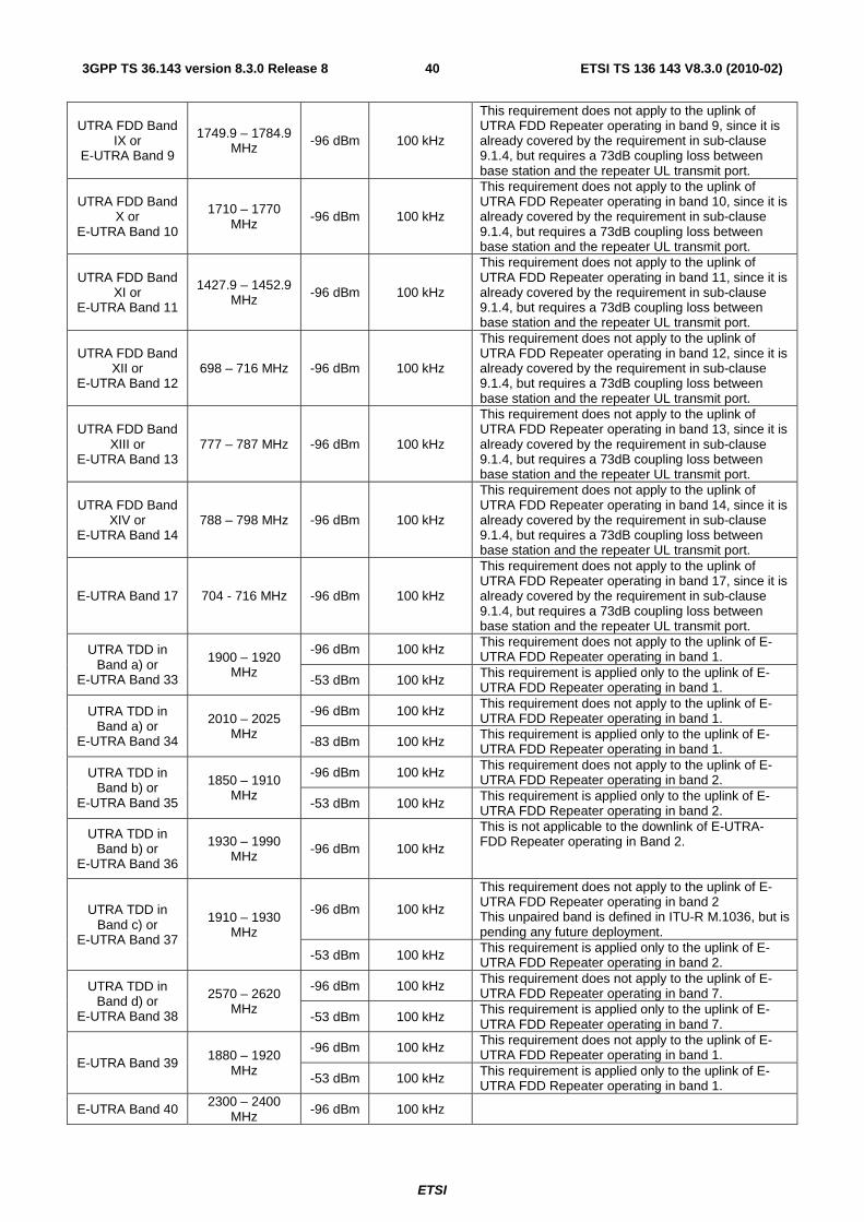
ETSI
ETSI TS 136 143 V8.3.0 (2010-02)403GPP TS 36.143 version 8.3.0 Release 8
UTRA FDD Band IX or
E-UTRA Band 9
1749.9 – 1784.9 MHz -96 dBm 100 kHz
This requirement does not apply to the uplink of UTRA FDD Repeater operating in band 9, since it is already covered by the requirement in sub-clause 9.1.4, but requires a 73dB coupling loss between base station and the repeater UL transmit port.
UTRA FDD Band X or
E-UTRA Band 10
1710 – 1770 MHz
-96 dBm 100 kHz
This requirement does not apply to the uplink of UTRA FDD Repeater operating in band 10, since it is already covered by the requirement in sub-clause 9.1.4, but requires a 73dB coupling loss between base station and the repeater UL transmit port.
UTRA FDD Band XI or
E-UTRA Band 11
1427.9 – 1452.9 MHz -96 dBm 100 kHz
This requirement does not apply to the uplink of UTRA FDD Repeater operating in band 11, since it is already covered by the requirement in sub-clause 9.1.4, but requires a 73dB coupling loss between base station and the repeater UL transmit port.
UTRA FDD Band XII or
E-UTRA Band 12 698 – 716 MHz -96 dBm 100 kHz
This requirement does not apply to the uplink of UTRA FDD Repeater operating in band 12, since it is already covered by the requirement in sub-clause 9.1.4, but requires a 73dB coupling loss between base station and the repeater UL transmit port.
UTRA FDD Band XIII or
E-UTRA Band 13 777 – 787 MHz -96 dBm 100 kHz
This requirement does not apply to the uplink of UTRA FDD Repeater operating in band 13, since it is already covered by the requirement in sub-clause 9.1.4, but requires a 73dB coupling loss between base station and the repeater UL transmit port.
UTRA FDD Band XIV or
E-UTRA Band 14 788 – 798 MHz -96 dBm 100 kHz
This requirement does not apply to the uplink of UTRA FDD Repeater operating in band 14, since it is already covered by the requirement in sub-clause 9.1.4, but requires a 73dB coupling loss between base station and the repeater UL transmit port.
E-UTRA Band 17 704 - 716 MHz -96 dBm 100 kHz
This requirement does not apply to the uplink of UTRA FDD Repeater operating in band 17, since it is already covered by the requirement in sub-clause 9.1.4, but requires a 73dB coupling loss between base station and the repeater UL transmit port.
UTRA TDD in Band a) or
E-UTRA Band 33
1900 – 1920 MHz
-96 dBm 100 kHz This requirement does not apply to the uplink of E-UTRA FDD Repeater operating in band 1.
-53 dBm 100 kHz This requirement is applied only to the uplink of E-UTRA FDD Repeater operating in band 1.
UTRA TDD in Band a) or
E-UTRA Band 34
2010 – 2025 MHz
-96 dBm 100 kHz This requirement does not apply to the uplink of E-UTRA FDD Repeater operating in band 1.
-83 dBm 100 kHz This requirement is applied only to the uplink of E-UTRA FDD Repeater operating in band 1.
UTRA TDD in Band b) or
E-UTRA Band 35
1850 – 1910 MHz
-96 dBm 100 kHz This requirement does not apply to the uplink of E-UTRA FDD Repeater operating in band 2.
-53 dBm 100 kHz This requirement is applied only to the uplink of E-UTRA FDD Repeater operating in band 2.
UTRA TDD in Band b) or
E-UTRA Band 36
1930 – 1990 MHz -96 dBm 100 kHz
This is not applicable to the downlink of E-UTRA-FDD Repeater operating in Band 2.
UTRA TDD in Band c) or
E-UTRA Band 37
1910 – 1930 MHz
-96 dBm 100 kHz
This requirement does not apply to the uplink of E-UTRA FDD Repeater operating in band 2 This unpaired band is defined in ITU-R M.1036, but is pending any future deployment.
-53 dBm 100 kHz This requirement is applied only to the uplink of E-UTRA FDD Repeater operating in band 2.
UTRA TDD in Band d) or
E-UTRA Band 38
2570 – 2620 MHz
-96 dBm 100 kHz This requirement does not apply to the uplink of E-UTRA FDD Repeater operating in band 7.
-53 dBm 100 kHz This requirement is applied only to the uplink of E-UTRA FDD Repeater operating in band 7.
E-UTRA Band 39 1880 – 1920
MHz
-96 dBm 100 kHz This requirement does not apply to the uplink of E-UTRA FDD Repeater operating in band 1.
-53 dBm 100 kHz This requirement is applied only to the uplink of E-UTRA FDD Repeater operating in band 1.
E-UTRA Band 40 2300 – 2400
MHz -96 dBm 100 kHz
ETSI
ETSI TS 136 143 V8.3.0 (2010-02)413GPP TS 36.143 version 8.3.0 Release 8
NOTE 1: As defined in the scope for spurious emissions in this clause, the co-location requirements in Table 9.2.5.4-1 do not apply for the 10 MHz frequency range immediately outside the repeaters operating band frequency range of an operating band (see Table 5.5-1). This is also the case when the repeaters operating band frequency range is adjacent to the frequency range of the co-location requirement in the Table 9.2.5.4-1. The current state-of-the-art technology does not allow a single generic solution for co-location with other system on adjacent frequencies for 30dB Repeater-BS minimum coupling loss. However, there are certain site-engineering solutions that can be used. These techniques are addressed in TR 25.942 [5].
NOTE 2: The Table 9.2.5.4-1 assumes that two operating bands, where the corresponding eNode B transmit and receive frequency ranges in Table 5.5-1 would be overlapping, are not deployed in the same geographical area. For such a case of operation with overlapping frequency arrangements in the same geographical area, special co-location requirements may apply that are not covered by the 3GPP specifications.
NOTE 3: The requirements of -53dBm/100kHz in Table 9.2.5.4-1 for the up link direction of the Repeater reflect what can be achieved with present state of the art technology and are based on a coupling loss of 73 dB between a Repeater and a UTRA TDD BS receiver.
NOTE 4: The requirements of -83dBm/100kHz in Table 9.2.5.4-1 for the up link direction of the Repeater reflect what can be achieved with present state of the art technology and are based on a coupling loss of 43 dB between a Repeater and a UTRA TDD BS receiver.
NOTE 5: The requirements of -53dBm/100kHz and -83dBm/100kHz in Table 9.2.5.4-1shall be reconsidered when the state of the art technology progresses.
10 Error Vector Magnitude (EVM)
10.1 Downlink Error Vector Magnitude
10.1.1 Definition and applicability
The Error Vector Magnitude is a measure of the difference between the ideal symbols and the measured symbols after the equalization. This difference is called the error vector. The equaliser parameters are estimated as defined in TS36.104 [4] Annex E. The EVM result is defined as the square root of the ratio of the mean error vector power to the mean reference power expressed in percent.
10.1.2 Minimum requirements
The minimum requirement is in TS 36.106 [2] subclause 10.1.1.
10.1.3 Test purpose
To verify that the downlink EVM deterioration is within the limit specified by the minimum requirements after the signal passed through the Repeater.
10.1.4 Method of test
10.1.4.1 Initial conditions
Test environment: normal; see Annex A2
A measurement system set-up is shown in annex C.
1) Connect the signal generator equipment to the Repeater input port.
2) Connect the signal analyser to the Repeater output port.

ETSI
ETSI TS 136 143 V8.3.0 (2010-02)423GPP TS 36.143 version 8.3.0 Release 8
10.1.4.2 Procedure
1) Set the signal generator to transmit one signal according to [ E-TM3.1] in TS 36.141 [11] of the widest possible bandwidth to fit into the Repeater pass band.
2) Adjust the input power to the Repeater to create the maximum nominal Repeater output power at maximum gain.
3) Measure the EVM and frequency error as defined in TS 36.141 [11] Annex F.
4) Repeat the procedure with all the narrower bandwidths of E-TM3.1
10.1.5 Test requirement
For the downlink of the Repeater the Error Vector Magnitude shall not exceed [8 % + 1,25%].
10.2 Uplink Error Vector Magnitude
10.2.1 Definition and applicability
The Error Vector Magnitude is a measure of the difference between the reference waveform and the measured waveform. This difference is called the error vector. Before calculating the EVM the measured waveform is corrected by the sample timing offset and RF frequency offset. Then the IQ origin offset shall be removed from the measured waveform before calculating the EVM.
The measured waveform is further modified by selecting the absolute phase and absolute amplitude of the Tx chain. The EVM result is defined after the front-end IDFT as the square root of the ratio of the mean error vector power to the mean reference power expressed as a %. The basic EVM measurement interval is one slot in the time domain.
10.2.2 Minimum requirements
The minimum requirement is in TS 36.106 [2] subclause 10.2.1.
10.2.3 Test purpose
To verify that the uplink EVM deterioration is within the limit specified by the minimum requirements after the signal passed through the Repeater.
10.2.4 Method of test
10.2.4.1 Initial conditions
Test environment: normal; see Annex A2
A measurement system set-up is shown in annex C.
1) Connect the signal generator equipment to the Repeater input port.
2) Connect the signal analyser to the Repeater output port.
10.2.4.2 Procedure
1) Set the signal generator to transmit the widest bandwidth UL reference signal according to Table A.2.2.1.2-1 in TS36.521-1 [12], that can be fitted inside the repeater passband.
2) Adjust the input power to the Repeater to create the maximum nominal Repeater output power at maximum gain.
3) Measure the EVM and frequency error as defined in TS 36.521-1 [12] Annex E.

ETSI
ETSI TS 136 143 V8.3.0 (2010-02)433GPP TS 36.143 version 8.3.0 Release 8
4) Repeat the procedure for all narrower BW UL reference signals according to Table A.2.2.1.2-1 in TS36.521-1 [12].
10.2.5 Test requirement
For the uplink of the Repeater the Error Vector Magnitude shall not exceed [8 % +1,25%].
11 Input intermodulation The input intermodulation is a measure of the capability of the Repeater to inhibit the generation of interference in the pass band, in the presence of interfering signals on frequencies other than the pass band.
11.1 Definition and applicability Third and higher order mixing of the two interfering RF signals can produce an interfering signal in the band of the desired channel. Intermodulation response rejection is a measure of the capability of the Repeater to maintain the wanted frequency free of internally created interference.
The additional input intermodulation test requirements in Tables 11.5.2-1 may be applied for the protection of an E-UTRA FDD Repeater input when GSM900, DCS1800, PCS1900, GSM850, UTRA FDD, UTRA TDD and/or E-UTRA BS are co-located with an E-UTRA FDD Repeater.
The additional input intermodulation test requirements in Tables 11.5.3-1 may be applied when GSM900, DCS1800, PCS1900, GSM850, UTRA FDD, UTRA TDD and/or E-UTRA BS operating in another frequency band co-exist with an E-UTRA FDD Repeater.
The measurements shall apply to both paths uplink and downlink of the Repeater, at maximum gain.
11.2 Minimum requirements The minimum requirements are in TS 36.106 [2] sub-clause 11.1.1, 11.2.1 and 11.3.1.
11.3 Test purpose The purpose of this test is to verify that the Repeater meets the intermodulation characteristics requirements as specified by the minimum requirements.
11.4 Method of test
11.4.1 Initial conditions
Test environment: normal; see Annex A2.
A measurement system set-up is shown in annex C.
1) Set the Repeater to maximum gain.
2) Connect two signal generators with a combining circuit or one signal generator with the ability to generate several CW carriers to the input.
3) Connect a spectrum analyser to the output of the Repeater. Set the resolution bandwidth to 1 MHz in the centre of the pass band. Set averaging to 1 second or more.
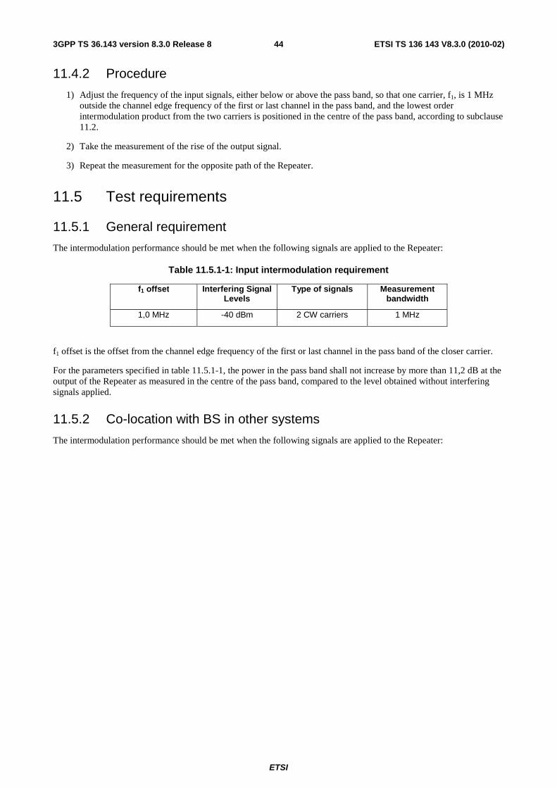
ETSI
ETSI TS 136 143 V8.3.0 (2010-02)443GPP TS 36.143 version 8.3.0 Release 8
11.4.2 Procedure
1) Adjust the frequency of the input signals, either below or above the pass band, so that one carrier, f1, is 1 MHz outside the channel edge frequency of the first or last channel in the pass band, and the lowest order intermodulation product from the two carriers is positioned in the centre of the pass band, according to subclause 11.2.
2) Take the measurement of the rise of the output signal.
3) Repeat the measurement for the opposite path of the Repeater.
11.5 Test requirements
11.5.1 General requirement
The intermodulation performance should be met when the following signals are applied to the Repeater:
Table 11.5.1-1: Input intermodulation requirement
f1 offset Interfering Signal Levels
Type of signals Measurement bandwidth
1,0 MHz -40 dBm 2 CW carriers 1 MHz
f1 offset is the offset from the channel edge frequency of the first or last channel in the pass band of the closer carrier.
For the parameters specified in table 11.5.1-1, the power in the pass band shall not increase by more than 11,2 dB at the output of the Repeater as measured in the centre of the pass band, compared to the level obtained without interfering signals applied.
11.5.2 Co-location with BS in other systems
The intermodulation performance should be met when the following signals are applied to the Repeater:

ETSI
ETSI TS 136 143 V8.3.0 (2010-02)453GPP TS 36.143 version 8.3.0 Release 8
Table 11.5.2-1: Input intermodulation requirements for interfering signals in co-located other systems
Co-located other
systems
Frequency of interfering
signals
Interfering Signal Levels
Type of signals
Measurement
bandwidth
Note
GSM900 921 – 960 MHz +16 dBm 2 CW
carriers 1 MHz
This requirement does not apply to E-UTRA FDD Repeater operating in band 8, since it is already covered by the requirement in sub-clause 11.5.1, but requires a 86dB coupling loss between base station and the repeater DL receive port.
DCS1800 1805 – 1880
MHz +16 dBm 2 CW
carriers 1 MHz
This requirement does not apply to E-UTRA FDD Repeater operating in band 3, since it is already covered by the requirement in sub-clause 11.5.1, but requires a 86dB coupling loss between base station and the repeater DL receive port.
PCS1900 1930 – 1990 MHz +16 dBm 2 CW
carriers 1 MHz
This requirement does not apply to E-UTRA FDD Repeater operating in band 2, since it is already covered by the requirement in sub-clause 11.5.1, but requires a 86dB coupling loss between base station and the repeater DL receive port.
GSM850 869 – 894 MHz +16 dBm 2 CW
carriers 1 MHz
This requirement does not apply to E-UTRA FDD Repeater operating in band 5, since it is already covered by the requirement in sub-clause 11.5.1, but requires a 86dB coupling loss between base station and the repeater DL receive port.
UTRA-FDD Band I or E-UTRA Band 1
2110 – 2170 MHz
+16 dBm 2 CW carriers
1 MHz
This requirement does not apply to E-UTRA FDD Repeater operating in band 1, since it is already covered by the requirement in sub-clause 11.5.1, but requires a 86dB coupling loss between base station and the repeater DL receive port.
UTRA-FDD Band II or E-UTRA Band 2
1930 – 1990 MHz +16 dBm 2 CW
carriers 1 MHz
This requirement does not apply to E-UTRA FDD Repeater operating in band 2, since it is already covered by the requirement in sub-clause 11.5.1, but requires a 86dB coupling loss between base station and the repeater DL receive port.
UTRA-FDD Band III or E-UTRA Band 3
1805 – 1880 MHz +16 dBm 2 CW
carriers 1 MHz
This requirement does not apply to E-UTRA FDD Repeater operating in band 3, since it is already covered by the requirement in sub-clause 11.5.1, but requires a 86dB coupling loss between base station and the repeater DL receive port.
UTRA-FDD Band IV or E-UTRA Band 4
2110 – 2155 MHz +16 dBm 2 CW
carriers 1 MHz
This requirement does not apply to E-UTRA FDD Repeater operating in band 4, since it is already covered by the requirement in sub-clause 11.5.1, but requires a 86dB coupling loss between base station and the repeater DL receive port.
UTRA-FDD Band V or E-UTRA Band 5
869 – 894 MHz +16 dBm 2 CW
carriers 1 MHz
This requirement does not apply to E-UTRA FDD Repeater operating in band 5, since it is already covered by the requirement in sub-clause 11.5.1, but requires a 86dB coupling loss between base station and the repeater DL receive port.
UTRA-FDD Band VI or E-UTRA Band 6
875 – 885 MHz +16 dBm
2 CW carriers 1 MHz
This requirement does not apply to E-UTRA FDD Repeater operating in band 6, since it is already covered by the requirement in sub-clause 11.5.1, but requires a 86dB coupling loss between base station and the repeater DL receive port.
UTRA-FDD Band VII or
E-UTRA
2620 – 2690 MHz +16 dBm 2 CW
carriers 1 MHz This requirement does not apply to E-UTRA FDD Repeater operating in band 7, since it is already covered by the requirement in

ETSI
ETSI TS 136 143 V8.3.0 (2010-02)463GPP TS 36.143 version 8.3.0 Release 8
Band 7 sub-clause 11.5.1, but requires a 86dB coupling loss between base station and the repeater DL receive port.
UTRA-FDD Band VIII or
E-UTRA Band 8
925 – 960 MHz +16 dBm 2 CW
carriers 1 MHz
This requirement does not apply to E-UTRA FDD Repeater operating in band 8, since it is already covered by the requirement in sub-clause 11.5.1, but requires a 86dB coupling loss between base station and the repeater DL receive port.
UTRA-FDD Band IX or E-UTRA Band 9
1844.9 – 1879.9 MHz +16 dBm 2 CW
carriers 1 MHz
This requirement does not apply to E-UTRA FDD Repeater operating in band 9, since it is already covered by the requirement in sub-clause 11.5.1, but requires a 86dB coupling loss between base station and the repeater DL receive port.
UTRA-FDD Band X or E-UTRA Band 10
2110 – 2170 MHz +16 dBm 2 CW
carriers 1 MHz
This requirement does not apply to E-UTRA FDD Repeater operating in band 10, since it is already covered by the requirement in sub-clause 11.5.1, but requires a 86dB coupling loss between base station and the repeater DL receive port.
UTRA-FDD Band XI or E-UTRA Band 11
1475.9 – 1500.9 MHz +16 dBm 2 CW
carriers 1 MHz
This requirement does not apply to E-UTRA FDD Repeater operating in band 11, since it is already covered by the requirement in sub-clause 11.5.1, but requires a 86dB coupling loss between base station and the repeater DL receive port.
UTRA FDD Band XII or
E-UTRA Band 12
728 – 746 MHz +16 dBm
2 CW carriers 1 MHz
This requirement does not apply to E-UTRA FDD Repeater operating in band 12, since it is already covered by the requirement in sub-clause 11.5.1, but requires a 86dB coupling loss between base station and the repeater DL receive port.
UTRA FDD Band XIII or
E-UTRA Band 13
746 – 756 MHz +16 dBm 2 CW
carriers 1 MHz
This requirement does not apply to E-UTRA FDD Repeater operating in band 13, since it is already covered by the requirement in sub-clause 11.5.1, but requires a 86dB coupling loss between base station and the repeater DL receive port.
UTRA FDD Band XIV or
E-UTRA Band 14
758 – 768 MHz +16 dBm 2 CW
carriers 1 MHz
This requirement does not apply to E-UTRA FDD Repeater operating in band 14, since it is already covered by the requirement in sub-clause 11.5.1, but requires a 86dB coupling loss between base station and the repeater DL receive port.
E-UTRA Band 17
734 - 746 MHz +16 dBm 2 CW carriers
1 MHz
This requirement does not apply to E-UTRA FDD Repeater operating in band 17, since it is already covered by the requirement in sub-clause 11.5.1, but requires a 86dB coupling loss between base station and the repeater DL receive port.
UTRA TDD in Band a)
or E-UTRA Band 33
1900 – 1920 MHz +16 dBm 2 CW
carriers 1 MHz
UTRA TDD in Band a)
or E-UTRA Band 34
2010 – 2025 MHz +16 dBm 2 CW
carriers 1 MHz
UTRA TDD in Band b)
or E-UTRA Band 35
1850 – 1910 MHz +16 dBm 2 CW
carriers 1 MHz
UTRA TDD in Band b)
1930 – 1990 MHz +16 dBm 2 CW
carriers 1 MHz This requirement does not apply to the downlink of E-UTRA FDD Repeater

ETSI
ETSI TS 136 143 V8.3.0 (2010-02)473GPP TS 36.143 version 8.3.0 Release 8
or E-UTRA Band 36
operating in band 2.
UTRA TDD in Band c)
or E-UTRA Band 37
1910 – 1930 MHz +16 dBm 2 CW
carriers 1 MHz
This unpaired band is defined in ITU-R M.1036, but is pending any future deployment.
UTRA TDD in Band d)
or E-UTRA Band 38
2570 – 2620 MHz +16 dBm 2 CW
carriers 1 MHz
E-UTRA Band 39
1880 – 1920 MHz +16 dBm 2 CW
carriers 1 MHz
E-UTRA Band 40
2300 – 2400 MHz +16 dBm 2 CW
carriers 1 MHz
NOTE 1: The co-location requirements in Table 11.5.2-1 do not apply when the repeaters pass band frequency range is adjacent to the frequency range of the co-location requirement in the Table 11.5.2-1. The current state-of-the-art technology does not allow a single generic solution for co-location with other system on adjacent frequencies for 30dB Repeater-BS minimum coupling loss. However, there are certain site-engineering solutions that can be used. These techniques are addressed in TR 25.942 [5].
NOTE 2: The Table 11.5.2-1 assumes that two operating bands, where the corresponding eNode B transmit and receive frequency ranges in Table 5.5-1 would be overlapping, are not deployed in the same geographical area. For such a case of operation with overlapping frequency arrangements in the same geographical area, special co-location requirements may apply that are not covered by the 3GPP specifications.
For the parameters specified in table 11.5.2-1, the power in the pass band shall not increase with more than 11,2 dB at the output of the repeater as measured in the centre of the pass band, compared to the level obtained without interfering signals applied.
11.5.3 Co-existence with other systems
The intermodulation performance should be met when the following signals are applied to the Repeater:
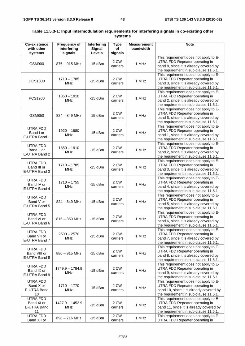
ETSI
ETSI TS 136 143 V8.3.0 (2010-02)483GPP TS 36.143 version 8.3.0 Release 8
Table 11.5.3-1: Input intermodulation requirements for interfering signals in co-existing other systems
Co-existence with other systems
Frequency of interfering
signals
Interfering Signal Levels
Type of
signals
Measurement bandwidth
Note
GSM900 876 – 915 MHz -15 dBm 2 CW carriers
1 MHz
This requirement does not apply to E-UTRA FDD Repeater operating in band 8, since it is already covered by the requirement in sub-clause 11.5.1.
DCS1800 1710 – 1785 MHz -15 dBm 2 CW
carriers 1 MHz
This requirement does not apply to E-UTRA FDD Repeater operating in band 3, since it is already covered by the requirement in sub-clause 11.5.1.
PCS1900 1850 – 1910 MHz -15 dBm 2 CW
carriers 1 MHz
This requirement does not apply to E-UTRA FDD Repeater operating in band 2, since it is already covered by the requirement in sub-clause 11.5.1.
GSM850 824 – 849 MHz -15 dBm 2 CW carriers 1 MHz
This requirement does not apply to E-UTRA FDD Repeater operating in band 5, since it is already covered by the requirement in sub-clause 11.5.1.
UTRA FDD Band I or
E-UTRA Band 1
1920 – 1980 MHz -15 dBm 2 CW
carriers 1 MHz
This requirement does not apply to E-UTRA FDD Repeater operating in band 1, since it is already covered by the requirement in sub-clause 11.5.1.
UTRA FDD Band II or
E-UTRA Band 2
1850 – 1910 MHz -15 dBm 2 CW
carriers 1 MHz
This requirement does not apply to E-UTRA FDD Repeater operating in band 2, since it is already covered by the requirement in sub-clause 11.5.1.
UTRA FDD Band III or
E-UTRA Band 3
1710 – 1785 MHz -15 dBm 2 CW
carriers 1 MHz
This requirement does not apply to E-UTRA FDD Repeater operating in band 3, since it is already covered by the requirement in sub-clause 11.5.1.
UTRA FDD Band IV or
E-UTRA Band 4
1710 – 1755 MHz
-15 dBm 2 CW carriers
1 MHz
This requirement does not apply to E-UTRA FDD Repeater operating in band 4, since it is already covered by the requirement in sub-clause 11.5.1.
UTRA FDD Band V or
E-UTRA Band 5 824 – 849 MHz -15 dBm
2 CW carriers 1 MHz
This requirement does not apply to E-UTRA FDD Repeater operating in band 5, since it is already covered by the requirement in sub-clause 11.5.1.
UTRA FDD Band VI or
E-UTRA Band 6 815 – 850 MHz -15 dBm 2 CW
carriers 1 MHz
This requirement does not apply to E-UTRA FDD Repeater operating in band 6, since it is already covered by the requirement in sub-clause 11.5.1.
UTRA FDD Band VII or
E-UTRA Band 7
2500 – 2570 MHz -15 dBm 2 CW
carriers 1 MHz
This requirement does not apply to E-UTRA FDD Repeater operating in band 7, since it is already covered by the requirement in sub-clause 11.5.1.
UTRA FDD Band VIII or
E-UTRA Band 8 880 – 915 MHz -15 dBm 2 CW
carriers 1 MHz
This requirement does not apply to E-UTRA FDD Repeater operating in band 8, since it is already covered by the requirement in sub-clause 11.5.1.
UTRA FDD Band IX or
E-UTRA Band 9
1749.9 – 1784.9 MHz -15 dBm 2 CW
carriers 1 MHz
This requirement does not apply to E-UTRA FDD Repeater operating in band 9, since it is already covered by the requirement in sub-clause 11.5.1.
UTRA FDD Band X or
E-UTRA Band 10
1710 – 1770 MHz -15 dBm 2 CW
carriers 1 MHz
This requirement does not apply to E-UTRA FDD Repeater operating in band 10, since it is already covered by the requirement in sub-clause 11.5.1.
UTRA FDD Band XI or
E-UTRA Band 11
1427.9 – 1452.9 MHz
-15 dBm 2 CW carriers
1 MHz
This requirement does not apply to E-UTRA FDD Repeater operating in band 11, since it is already covered by the requirement in sub-clause 11.5.1.
UTRA FDD Band XII or 698 – 716 MHz -15 dBm 2 CW
carriers 1 MHz This requirement does not apply to E-UTRA FDD Repeater operating in

ETSI
ETSI TS 136 143 V8.3.0 (2010-02)493GPP TS 36.143 version 8.3.0 Release 8
E-UTRA Band 12
band 12, since it is already covered by the requirement in sub-clause 11.5.1.
UTRA FDD Band XIII or
E-UTRA Band 13
777 – 787 MHz -15 dBm 2 CW
carriers 1 MHz
This requirement does not apply to E-UTRA FDD Repeater operating in band 13, since it is already covered by the requirement in sub-clause 11.5.1.
UTRA FDD Band XIV or
E-UTRA Band 14
788 – 798 MHz -15 dBm 2 CW carriers 1 MHz
This requirement does not apply to E-UTRA FDD Repeater operating in band 14, since it is already covered by the requirement in sub-clause 11.5.1.
E-UTRA Band 17 704 - 716 MHz -15 dBm 2 CW
carriers 1 MHz
This requirement does not apply to E-UTRA FDD Repeater operating in band 17, since it is already covered by the requirement in sub-clause 11.5.1.
UTRA TDD in Band a) or
E-UTRA Band 33
1900 – 1920 MHz -15 dBm 2 CW
carriers 1 MHz
UTRA TDD in Band a) or
E-UTRA Band 34
2010 – 2025 MHz -15 dBm 2 CW
carriers 1 MHz
UTRA TDD in Band b) or
E-UTRA Band 35
1850 – 1910 MHz -15 dBm 2 CW
carriers 1 MHz
UTRA TDD in Band b) or
E-UTRA Band 36
1930 – 1990 MHz
-15 dBm 2 CW carriers
1 MHz This requirement does not apply to the downlink of E-UTRA FDD Repeater operating in band 2.
UTRA TDD in Band c) or
E-UTRA Band 37
1910 – 1930 MHz -15 dBm
2 CW carriers 1 MHz
This unpaired band is defined in ITU-R M.1036, but is pending any future deployment.
UTRA TDD in Band d) or
E-UTRA Band 38
2570 – 2620 MHz -15 dBm 2 CW
carriers 1 MHz
E-UTRA Band 39
1880 – 1920 MHz -15 dBm
2 CW carriers 1 MHz
E-UTRA Band 40
2300 – 2400 MHz -15 dBm 2 CW
carriers 1 MHz
NOTE 1: The co-existence requirements in Table 11.5.3-1 do not apply when the repeaters pass band frequency range is adjacent to the frequency range of the co-existence requirement in the Table 11.3.1-1. The current state-of-the-art technology does not allow a single generic solution for co-existence.
NOTE 2: The Table 11.5.3-1 assumes that two operating bands, where the frequency ranges in Table 5.5-1 would be overlapping, are not deployed in the same geographical area. For such a case of operation with overlapping frequency arrangements in the same geographical area, special co-existence requirements may apply that are not covered by the 3GPP specifications.
For the parameters specified in table 11.5.3-1, the power in the pass band shall not increase with more than 11,2 dB at the output of the repeater as measured in the centre of the pass band, compared to the level obtained without interfering signals applied.

ETSI
ETSI TS 136 143 V8.3.0 (2010-02)503GPP TS 36.143 version 8.3.0 Release 8
12 Output intermodulation
12.1 Definition and applicability The output intermodulation requirement is a measure of the ability of the repeater to inhibit the generation of intermodulation products signals created by the presence of an interfering signal reaching the repeater via the output port.
The output intermodulation level is the power of the intermodulation products when a E-UTRA signal of channel bandwidth 5 MHz as an interference signal is injected into the output port at a level of 30 dB lower than that of the wanted signal. The wanted signal channel bandwidth BWChannel shall be the maximum bandwidth supported by the repeater. The Interfering signal centre frequency offset from wanted signal carrier centre frequency shall be according to the table 12.1-1..
The requirement shall apply to the downlink of the Repeater, at maximum gain.
Table 12.1-1 Interfering and wanted signals for the output intermodulation requirement
Parameter Value Wanted signal E-UTRA signal of maximum channel bandwidth
BWChannel Interfering signal type E-UTRA signal of channel bandwidth 5 MHz Interfering signal level Mean power level 30 dB below the mean power
of the wanted signal Interfering signal centre frequency offset from wanted signal carrier centre frequency
-BWChannel /2 - 12,5 MHz -BWChannel /2 - 7,5 MHz -BWChannel /2 - 2,5 MHz BWChannel /2 + 2,5 MHz BWChannel /2 + 7,5 MHz BWChannel /2 + 12,5 MHz
NOTE: Interfering signal positions that are partially or completely outside of the downlink operating band of the repeater are excluded from the requirement.
12.2 Minimum requirement The minimum requirement is in TS 36.106 [2] subclause 12.1.
12.3 Test purpose The test purpose is to verify the ability of the repeater to restrict the generation of intermodulation products in the presence of a subject signal on the repeater input and output ports, and an interfering signal applied at the repeater output port.
12.4 Method of test
12.4.1 Initial conditions
Test environment: normal; see Annex A2.
A measurement system set-up is shown in annex C.
1) Connect a signal generator to the input port of the Repeater (wanted signal). Connect a signal generator to the circulator on the output port (interfering signal) and make sure the signal generator power is directed to the repeater output port.
2) Detection mode: True RMS.

ETSI
ETSI TS 136 143 V8.3.0 (2010-02)513GPP TS 36.143 version 8.3.0 Release 8
12.1.4.2 Procedure
1) Set the Repeater to maximum gain.
2) Set the signal generator at the repeater input port (wanted signal) to generate a signal in accordance to test model E-TM 1.1, TS 36.141 subclause 6.1.1.1, with a bandwidth as defined in table 12.1-1, at the level which produce the manufacturer specified maximum output power at maximum gain.
3) Set the signal generator at the repeater output port (interference signal) to generate a signal in accordance to test model E-TM 1.1, TS 36.141 subclause 6.1.1.1, with a bandwidth, level and frequency offset as defined in table 12.1-1.
4) Measure the emission at the specified frequencies with specified measurement bandwidth as described in the test requirements and note that the measured value does not exceed the specified value. Measurements in the band of the interfering signal shall be excluded. The measurements can be limited to the power of all third and fifth order intermodulation products.
5) Repeat the test from step 3 on until all interfering signal centre frequency offsets in table 12.1-1 has been tested, but exclude interfering signal frequencies that are outside of the allocated frequency band for E-UTRA downlink specified in subclause 5.3.
NOTE: As a general rule the resolution bandwidth of the measuring equipment should be equal to the measurement bandwidth. However, to improve measurement accuracy, sensitivity and efficiency, the resolution bandwidth can be smaller than the measurement bandwidth. When the resolution bandwidth is smaller than the measurement bandwidth, the result should be integrated over the measurement bandwidth in order to obtain the equivalent noise bandwidth of the measurement bandwidth.
12.5 Test Requirements In all measurements, the requirements according to either subclause 9.1.5.1 Operating band unwanted emission (Category A) and the downlink requirements of 9.2.5.1 Spurious emission (Category A) or 9.1.5.2 Operating band unwanted emissions (Category B) and the downlink requirements of 9.2.5.2 Spurious emission (Category B) shall be fulfilled.
13 Adjacent Channel Rejection Ratio (ACRR)
13.1 Definitions and applicability Adjacent Channel Rejection Ratio (ACRR) is the ratio of the RRC weighted gain per carrier of the repeater in the pass band to the RRC weighted gain of the repeater on an adjacent channel outside the repeater pass band. The carrier in the pass band and in the adjacent channel shall be of the same type (reference carrier).
The requirement shall apply to the uplink and downlink of the Repeater, at maximum gain, where the donor link is maintained via antennas (over the air Repeater).
13.1.1 Minimum requirements
There is no minimum requirement for E-UTRA signals
13.2 Co-existence with UTRA This requirement shall be applied for the protection of UTRA signals in geographic areas in which E-UTRA-FDD Repeater and UTRA BS are deployed so that they serve adjacent channels. The reference carrier is a UTRA-FDD carrier.

ETSI
ETSI TS 136 143 V8.3.0 (2010-02)523GPP TS 36.143 version 8.3.0 Release 8
13.2.1 Minimum requirements
The minimum requirement is in TS 36.106 [2] sub-clause 13.2.1.
13.2.2 Test purpose
To verify that the Repeater ACRR requirement is met as specified in sub-clause 13.2.1.
13.2.3 Method of test
13.2.3.1 Initial conditions
Test environment: normal; see Annex A2.
A measurement system set-up is shown in annex C.
1) Connect the signal generator equipment to the Repeater input port.
2) Connect the power measuring equipment to the Repeater output port.
3) The measurement device characteristics shall be:
- measurement filter bandwidth: defined in sub-clause 13.1;
- detection mode: true RMS voltage or true average power.
13.2.3.2 Procedure
1) Set the signal generator to transmit a signal modulated with a combination of PCCPCH, SCCPCH and Dedicated Physical Channels specified as test model 1 in TS 25.141 at the first or last 5 MHz channel within the pass band.
2) Adjust the input power to the Repeater to create the maximum nominal Repeater output power at maximum gain
3) Measure the RRC filtered mean power at the RF output port over a certain slot.
4) Set the signal generator to transmit the same signal and the same input power at one of the channel offsets outside the repeater pass band according to Table 13.2-1.
5) Measure the RRC filtered mean power at the RF output port over a certain slot.
6) Calculate the ratio of the measured power in the pass band to the measured power at the channel offset.
7) Repeat step 4) to 6) until all channel offsets in Table 13.2-1 are measured.
13.2.3.3 Test Requirements
In normal conditions as specified in annex A.2, the ACRR shall be higher than the value specified in the Table 13.2-1.
Table 13.2-1: Repeater ACRR
Repeater maximum output power
Channel offset from the centre frequency of the first or last 5 MHz
channel within the pass band.
ACRR limit
P ≥ 31 dBm 5 MHz 32,3dB P ≥ 31 dBm 10 MHz 32,3dB P < 31 dBm 5 MHz 19,3dB P < 31 dBm 10 MHz 19,3dB
Note: Repeater maximum output power as defined in TS25.143 clause 9.1.1.
ETSI
ETSI TS 136 143 V8.3.0 (2010-02)533GPP TS 36.143 version 8.3.0 Release 8
Annex A (normative): Environmental requirements for the Repeater
A.1 General For each test in the present document, the environmental conditions under which the Repeater is to be tested are defined.
A.2 Normal test environment When a normal test environment is specified for a test, the test should be performed within the minimum and maximum limits of the conditions stated in Table A.1-1.
Table A.1-1: Limits of conditions for Normal Test Environment
Condition Minimum Maximum Barometric pressure 86 kPa 106 kPa Temperature 15°C 30°C Relative Humidity 20 % 85 % Power supply Nominal, as declared by the manufacturer Vibration Negligible
The ranges of barometric pressure, temperature and humidity represent the maximum variation expected in the uncontrolled environment of a test laboratory. If it is not possible to maintain these parameters within the specified limits, the actual values shall be recorded in the test report.
NOTE: This may, for instance, be the case for measurements of radiated emissions performed on an open field test site.
A.3 Extreme test environment The manufacturer shall declare one of the following:
1) the equipment class for the equipment under test, as defined in the IEC 60 721-3-3 [6];
2) the equipment class for the equipment under test, as defined in the IEC 60 721-3-4 [7];
3) the equipment that does not comply to the mentioned classes, the relevant classes from IEC 60 721 documentation for Temperature, Humidity and Vibration shall be declared.
NOTE: Reduced functionality for conditions that fall out side of the standard operational conditions are not tested in the present document. These may be stated and tested separately.
A.3.1 Extreme temperature
When an extreme temperature test environment is specified for a test, the test shall be performed at the standard minimum and maximum operating temperatures defined by the manufacturer"s declaration for the equipment under test.
Minimum temperature:
The test shall be performed with the environment test equipment and methods including the required environmental phenomena into the equipment, conforming to the test procedure of IEC 60 068-2-1 [8].
Maximum temperature:

ETSI
ETSI TS 136 143 V8.3.0 (2010-02)543GPP TS 36.143 version 8.3.0 Release 8
The test shall be performed with the environmental test equipment and methods including the required environmental phenomena into the equipment, conforming to the test procedure of IEC 60 068-2-2 [9].
NOTE: It is recommended that the equipment is made fully operational prior to the equipment being taken to its lower operating temperature.
A.4 Vibration When vibration conditions are specified for a test, the test shall be performed while the equipment is subjected to a vibration sequence as defined by the manufacturer"s declaration for the equipment under test. This shall use the environmental test equipment and methods of inducing the required environmental phenomena in to the equipment, conforming to the test procedure of IEC 60 068-2-6 [10]. Other environmental conditions shall be within the ranges specified in clause A.2.
NOTE: The higher levels of vibration may induce undue physical stress in to equipment after a prolonged series of tests. The testing body should only vibrate the equipment during the RF measurement process.
A.5 Power supply When extreme power supply conditions are specified for a test, the test shall be performed at the standard upper and lower limits of operating voltage defined by manufacturer"s declaration for the equipment under test.
Upper voltage limit:
The equipment shall be supplied with a voltage equal to the upper limit declared by the manufacturer (as measured at the input terminals to the equipment). The tests shall be carried out at the steady state minimum and maximum temperature limits declared by the manufacturer for the equipment, to the methods described in IEC 60 068-2-1 [8] Test Ab/Ad and IEC 60 068-2-2 [9] Test Bb/Bd: Dry Heat.
Lower voltage limit:
The equipment shall be supplied with a voltage equal to the lower limit declared by the manufacturer (as measured at the input terminals to the equipment). The tests shall be carried out at the steady state minimum and maximum temperature limits declared by the manufacturer for the equipment, to the methods described in IEC 60 068-2-1 [8] Test Ab/Ad and IEC 60 068-2-2 [9] Test Bb/Bd: Dry Heat.
A.6 Measurement of test environments The measurement accuracy of the Repeater test environments defined in Annex A, Test environments shall be.
Pressure: ±5 kPa. Temperature: ±2 degrees. Relative Humidity: ±5 %. DC Voltage: ±1,0 %. AC Voltage: ±1,5 %. Vibration: 10 %. Vibration frequency: 0,1 Hz.
The above values shall apply unless the test environment is otherwise controlled and the specification for the control of the test environment specifies the uncertainty for the parameter.

ETSI
ETSI TS 136 143 V8.3.0 (2010-02)553GPP TS 36.143 version 8.3.0 Release 8
Annex B (informative): Test tolerances and derivation of test requirements The test requirements in this specification have been calculated by relaxing the minimum requirements of the core specification using the Test Tolerances defined here. When the test tolerance is zero, the test requirement will be the same as the minimum requirement. When the test tolerance is non-zero, the test requirements will differ from the minimum requirements, and the formula used for this relaxation is given in the following tables.
The test tolerances are derived from test system uncertainties, regulatory requirements and criticality to system performance. As a result, the test tolerances may sometimes be set to zero.
The test tolerances should not be modified for any reason e.g. to take account of commonly known test system errors (such as mismatch, cable loss, etc.).
Note that a formula for applying test tolerances is provided for all tests, even those with a test tolerance of zero. This is necessary in the case where the test system uncertainty is greater than that allowed in clause 4.1.2. In this event, the excess error shall be subtracted from the defined test tolerance in order to generate the correct tightened test requirements as defined in this annex.
[FFS: For example, a test system having 0.9 dB uncertainty for test 6 maximum output power (which is 0.2 dB above the limit specified in clause 4.1.2) would subtract 0.2 dB from the test tolerance of 0.7 dB defined in this annex. This new test tolerance of 0.5 dB would then be applied to the minimum requirement using the formula defined in Table B.2-1 to give a new range of ±2.5 dB of the manufacturer"s rated output power.
Using this same approach for the case where a test had a test tolerance of 0 dB, an excess error of 0.2 dB would result in a modified test tolerance of -0.2 dB.]

ETSI
ETSI TS 136 143 V8.3.0 (2010-02)563GPP TS 36.143 version 8.3.0 Release 8
Table B.1-1: Derivation of test requirements
Clause number
Title Minimum Requirement in TS 36.106
Test Tolerance
(TT)
Test Requirement in TS 36.143
6 Output power
Formula: Upper limit + TT Lower limit – TT
In normal conditions within ±2 dB of manufacturer"s rated output power
0,7 dB In normal conditions: within +2.7 dB and -2.7 dB of the manufacturer"s rated output power
In extreme conditions within ±2,5 dB of manufacturer"s rated output power
0,7 dB In extreme conditions: within +3.2 dB and -3.2 dB of the manufacturer"s rated output power
7 Frequency error [0,001 ppm] [12 Hz] [Formula: Upper limit + TT Lower limit – TT ±(0,001 ppm + 12 Hz)]
8 Out of band gain Table 8.1-1 Out of band gain limits 1 Table 8.1-2 Out of band gain limits 2
0,5 dB Formula: Maximum limit + TT Table 8.5-1 and Table 8.5-2
9.1 Operating band unwanted emissions
Tables 9.1.1.1-1 to 9.1.1.1-4 (Category A) and tables 9.1.2.1-1 to 9.1.2.1-4 (Category B) Additional requirements in tables9.1.3.1-1 to 9.1.3-3 and 9.1.4.1-1.
General requirements: 1,5 dB inside 2 x pass band BW < 10 MHz from pass band edge. 0 dB elsewhere in the operating band 0 dB on additional requirements
Formula: Maximum level + TT Tables 9.1.5.1-1 to table 9.1.5.1-4 and tables 9.1.5.2-1 to 9.1.5.2-4. Tables 9.1.5.3-1 to 9.1.5.3-3 and 9.1.5.4-1
9.2 Spurious emissions Category A 9 kHz ≤ f < 150 kHz: -13dBm / 1kHz
150 kHz ≤ f < 30 MHz: -13dBm / 10 kHz
30 MHz ≤ f < 1 GHz: -13dBm / 100 kHz
1 GHz ≤ f < 12.75 GHz: -13dBm / 1 MHz
Category B 9 kHz ≤ f < 150 kHz: -36dBm / 1 kHz
150 kHz ≤ f < 30 MHz: -36dBm / 10 kHz
30 MHz ≤ f < 1 GHz: -36dBm / 100 kHz
1 GHz ≤ f < 12.75 GHz: -30dBm / 1 MHz Co-existence requirements in tables 9.2.2.1-1 to 9.2.2.1-3. Co-location requirements in table 9.2.3.1-1
0 dB Formula: Maximum level + TT Co-existence requirements in tables 9.2.5.3-1 to 9.2.5.3-3. Co-location requirements in table 9.2.5.4-1

ETSI
ETSI TS 136 143 V8.3.0 (2010-02)573GPP TS 36.143 version 8.3.0 Release 8
10 Error vector magnitude
[8%] [1.25%] Requirement limit shifted by RSS requirement and stimulus signal EVM. Analyser error added to requirement limit.
11 Input intermodulation
Maximum in-band power increase < 10 dB Tables 11.1.1-1, 11.2.1-1, and 11.3.1-1.
1,2 dB Maximum in-band power increase + TT
12 Output intermodulation
As in 9.1 and 9.2 As in 9.1 and 9.2
Maximum level + TT
13 Adjacent channel rejection ratio
Table 13.2.1-1 0,7 dB Formula: Limit – TT

ETSI
ETSI TS 136 143 V8.3.0 (2010-02)583GPP TS 36.143 version 8.3.0 Release 8
Annex C (informative): Measurement system set-up Example of measurement system set-ups are attached below as an informative annex.
C.1 Maximum output power
Figure C.1-1: Measuring system set-up for maximum output power
Note that a repeater is a bi-directional device. The signal generator may need protection.
C.2 Frequency stability
Figure C.2-1: Measurement system set-up for frequency stability
Note that a repeater is a bi-directional device. The signal generator may need protection.
Frequency counter
Repeater under test
CW Signal
Generator
Power Meter or equivalent
Repeater under test
E-UTRA Signal
Generator

ETSI
ETSI TS 136 143 V8.3.0 (2010-02)593GPP TS 36.143 version 8.3.0 Release 8
C.3 Out of band gain
Figure C.3-1: Measuring system set-up for out of band gain
Note that a repeater is a bi-directional device. The signal generator may need protection.
C.4 Unwanted emission: Operating band unwanted emission
Figure C.4-1: Measuring system set-up for unwanted emission: Operating band unwanted emission
Note that a repeater is a bi-directional device. The signal generator may need protection.
Spectrum analyser
Repeater under test
E-UTRA Signal
Generator
30 dB precission
Spectrum Analyser
Repeater under test
CW Signal
Generator 30 dB precission

ETSI
ETSI TS 136 143 V8.3.0 (2010-02)603GPP TS 36.143 version 8.3.0 Release 8
C.5 Unwanted emission: Spurious emission
Figure C.5-1: Measuring system set-up for unwanted emission: Spurious emission.
Note that a repeater is a bi-directional device. The signal generator may need protection.
C.6 Modulation Accuracy: Error Vector Magnitude
Figure C.6-1: Measuring system set-up for error vector magnitude.
Note that a repeater is a bi-directional device. The signal generator may need protection.
Spectrum analyser
Repeater under test
E-UTRA Signal
Generator
Signal analyser
Repeater under test
E-UTRA Signal
Generator

ETSI
ETSI TS 136 143 V8.3.0 (2010-02)613GPP TS 36.143 version 8.3.0 Release 8
C.7 Input intermodulation
Figure C.7-1: Measuring system set-up for input intermodulation.
Note that a repeater is a bi-directional device. The signal generator may need protection.
C.8 Output Intermodulation
Figure C.8-1: Measuring system set-up for output intermodulation.
Note that a repeater is a bi-directional device. The signal generator may need protection.
Repeater under test
Spectrum Analyser
E-UTRA Signal
Generator F1
Circulator
E-UTRA Signal
Generator F2
CW Generato
r Repeater
under test
Spectrum Analyser
Coupler
CW Generato
r

ETSI
ETSI TS 136 143 V8.3.0 (2010-02)623GPP TS 36.143 version 8.3.0 Release 8
C.9 Adjacent Channel Rejection Ratio
Figure C.9-1: Measuring system set-up for Adjacent Channel Rejection Ratio
Note that a repeater is a bi-directional device. The signal generator may need protection.
Spectrum Analyser
Repeater under test
WCDMA Signal
Generator

ETSI
ETSI TS 136 143 V8.3.0 (2010-02)633GPP TS 36.143 version 8.3.0 Release 8
Annex D (normative): Repeater stimulus signals
D.1 Repeater stimulus signal 1 This Repeater stimulus signal shall be used for tests on:
• Uplink maximum output power
• Uplink operating band unwanted emissions
• Uplink spurious emissions
Except in the case where the repeater under test has a pass band narrower than 2.8 MHz.
Two uplink fixed reference channels for performance requirements (16QAM ¾) for FDD according to the TS36.141 [11], A.4 table A.4-1, channel reference A4-3 of 1.4 MHz bandwidth generated on separate centre frequencies with equal power and combined with a time difference of [266,7 us (4 OFDM symbols)]
The PUSCH data payload shall contain only zeroes (0000 0000)
Each reference channel shall be subjected to time windowing and filtering so that it fulfils the spectral purity requirements defined in D.5
D.2 Repeater stimulus signal 2 This Repeater stimulus signal shall be used for tests on:
• Downlink operating band unwanted emissions
• Downlink spurious emissions
Except in the case where the repeater under test has a pass band narrower than 2.8 MHz.
Two E-TM1.1 channels according to the TS36.141 [11] of 1.4 MHz bandwidth generated on separate centre frequencies with equal power and combined with a time difference of [1400 us (21 OFDM symbols)].
Each E-TM1.1 channel shall be subjected to time windowing and filtering so that it fulfils the spectral purity requirements defined in D.5
D.3 Repeater stimulus signal 3 This Repeater stimulus signal shall be used for tests on:
• Uplink maximum output power
• Uplink operating band unwanted emissions
• Uplink spurious emissions
One uplink fixed reference channel for performance requirements (16QAM ¾) for FDD according to the TS36.141 [11], A.4 table A.4-1, channel reference A4-3 of 1.4 MHz bandwidth .
The PUSCH data payload shall contain only zeroes (0000 0000).

ETSI
ETSI TS 136 143 V8.3.0 (2010-02)643GPP TS 36.143 version 8.3.0 Release 8
The reference channel shall be subjected to time windowing and filtering so that it fulfils the spectral purity requirements defined in D.5.
D.4 Repeater stimulus signal 4 This Repeater stimulus signal shall be used for tests on:
• Downlink operating band unwanted emissions
• Downlink spurious emissions
In the case where the repeater under test has a pass band narrower than 2.8 MHz
One E-TM1.1 channels according to the TS36.141 [11] of 1.4 MHz.
The E-TM1.1 channel shall be subjected to time windowing and filtering so that it fulfils the spectral purity requirements defined in D.5.
D.5 Repeater stimulus signal spectral purity requirements The reference channels or test models constituting the repeater stimulus signal shall fulfil the spectral purity requirements defined by table D. 5-1, where;
- the reference spectral density shall be taken 200 kHz off the carrier centre frequency with an integration bandwidth of 30 kHz.
- Δf is the separation between the channel edge frequency and the nominal -3dB point of the measuring filter closest to the carrier frequency.
- f_offset is the separation between the channel edge frequency and the centre of the measuring filter.
- f_offsetmax is the offset to the frequency 10 MHz outside the downlink operating band.
- Δfmax is equal to f_offsetmax minus half of the bandwidth of the measuring filter.
- the minimum spectral density suppression is related to the reference spectral density.
Table D.5-1: Repeater stimulus signal spectral purity requirements
Frequency offset of measurement
filter -3dB point, Δf
Frequency offset of measurement filter centre
frequency, f_offset
Minimum requirement Measure-ment
bandwidth 0 MHz ≤ Δf < 0.15 MHz 0.015 MHz ≤ f_offset < 0.165
MHz -40 + 20*( f_offset -0.015) dBc 30 kHz
0.15 MHz ≤ Δf < 0.2 MHz
0.165 MHz ≤ f_offset < 0.215 MHz
-37 dBc 30 kHz
0.2 MHz ≤ Δf < 1 MHz 0.215 MHz ≤ f_offset < 1.015 MHz
( )dBoffsetfdBm 215.0_*1594 −−− 30 kHz
1.015 MHz ≤ f_offset < 1.5 MHz -106 dBm 30 kHz 1 MHz ≤ Δf < 2.8 MHz 1.5 MHz ≤ f_offset <
2.85 MHz -78 dBm 1 MHz
2.8 MHz ≤ Δf ≤ Δfmax 2.85 MHz ≤ f_offset < f_offsetmax
-80 dBm 1 MHz
NOTE: Frequencies and bandwidth are given in MHz

ETSI
ETSI TS 136 143 V8.3.0 (2010-02)653GPP TS 36.143 version 8.3.0 Release 8
Annex E (informative): Change history
Change history Date TSG # TSG Doc. CR Rev Subject/Comment Old New 2008-08 RAN4#48 R4-081757 36.143 TS skeleton created from 3GPP TS template. 0.0.1 2008-10 RAN4#48
bis R4-082275 Text proposals
R4-081758_36.143_TP_Scope-Reference-Definition-General R4-081759_36.143_TP_Frequency bands R4-081760_36.143_TP_Annex A Environmental requirements R4-081761_36.143_TP_Annex B Test Tolerances and Derivation of Test Requirements R4-081762_36.143_TP_Annex C Measurement system set-up which were agreed at RAN4#48, are incorporated
0.0.1 0.1.0
2008-11 RAN4#49 R4-082901 Text proposals which were agreed at RAN4#48bis, are incorporated R4-082276_36.143_TP_Output power R4-082277_TS36.143_TP_Out of band gain R4-082278_TS36.143 Operating band unwanted emissions R4-082279_36.143_TP_Spuriousemission R4-082282_36.143_TP_ACRR R4-082397Correction to the figure with the Transmission
Bandwidth Configuration
0.1.0 0.2.0
2008-11 RAN4#49 R4-082913 TS with the Text proposals agreed at RAN4#49 R4-083145 TS36.143 Operating band unwanted emission:
Correction of formula R4-083146 TS36.143 TP Input intermodulation R4-083147 TS36.143 TP Output intermodulation R4-083175 TS36.143 TP Measurement uncertainties and test
tolerances R4-082909 TS36.143 TP Measurement set ups Presentation to TSG RAN for information as RP-080865.zip
0.2.0 1.0.0
2009-01 RAN4#49bis
R4-090019 TS with the Text proposals agreed at RAN4#49bis R4-090014 TS36143 Clean-up R4-090018 TS36.143 Adding test tolerances to the requirements R4-090368 Clarification of PHS band including the future plan
1.0.0 1.1.0
2009-02 RAN4#50 R4-090931 TS with the Text proposals agreed at RAN4#50 R4-090573 TS36.143 Introducing E-TM into output power
measurements R4-090574 TS36.143 Introducing E-TM into operating band
unwanted emission measurements R4-090575 TS36.143 Introducing E-TM into spurious emission
measurements R4-090576 TS36.143 Clause 4: TP Manufacturer declaration R4-090579 TS36.143 TP EVM Presentation to TSG RAN
1.1.0 1.2.0
2009-02 RAN4#50 R4-090967 TS with the small text correction agreed at RAN4#50 Presentation to TSG RAN
1.2.0 1.3.0
2009-03 RAN #43 RP-090024 Presented for approval 1.3.0 2.0.0 2009-03 RAN #43 RP-090024 TS approved 2.0.0 8.0.0 2009-03 RAN #43 RP-090552 1 Clarification of EARFCN for 36.143. (Technically Endorsed CR in
R4-50bis - R4-091268) 8.0.0 8.1.0
2009-03 RAN #43 RP-090552 2 Alignement with core spec and clean-up 8.0.0 8.1.0 2009-03 RAN #43 RP-090552 3 Output intermodulation: Introduction of test models 8.0.0 8.1.0 2009-03 RAN #43 RP-090552 5 Repeater stimulus signal: time difference 8.0.0 8.1.0 2009-03 RAN #43 RP-090552 6 Frequency stability 8.0.0 8.1.0 2009-09 RAN #45 RP-090819 7 EVM for LTE Repeater : uncertainty and test tolerance 8.1.0 8.2.0 2009-09 RAN #45 RP-090819 8 Introduction of band 17 8.1.0 8.2.0 2009-09 RAN #45 RP-090819 9 EVM for LTE Repeater 8.1.0 8.2.0 2009-09 RAN #45 RP-090819 12 Clarificaton of testresult interpretation of repeater
operating band unwanted emissions. 8.1.0 8.2.0
2009-09 RAN #45 RP-090819 11 Repeater stimulus signals 8.1.0 8.2.0 2009-12 RAN #46 RP-091282 13 1 Update of operating band unwanted emissions for LTE Repeater 8.2.0 8.3.0 2009-12 RAN #46 RP-091282 14 Update of Repeater stimulus signals 8.2.0 8.3.0

ETSI
ETSI TS 136 143 V8.3.0 (2010-02)663GPP TS 36.143 version 8.3.0 Release 8
History
Document history
V8.0.0 March 2009 Publication
V8.1.0 July 2009 Publication
V8.2.0 October 2009 Publication
V8.3.0 February 2010 Publication