ts 101 343 - v06.06.00 - digital cellular ... · etsi ts 101 343 v6.6.0 (1999-12) technical...
TRANSCRIPT

ETSI TS 101 343 V6.6.0 (1999-12)Technical Specification
Digital cellular telecommunications system (Phase 2+);General Packet Radio Service (GPRS);
Base Station System (BSS) - Serving GPRS Support Node(SGSN);
BSS GPRS Protocol (BSSGP)(GSM 08.18 version 6.6.0 Release 1997)
GLOBAL SYSTEM FORMOBILE COMMUNICATIONS
R
ETSI
ETSI TS 101 343 V6.6.0 (1999-12)2(GSM 08.18 version 6.6.0 Release 1997)
ReferenceRTS/SMG-020818Q6R5
KeywordsDigital cellular telecommunications system,
Global System for Mobile communications (GSM)Service, Packet Mode, Radio, GSM,
GSM_Phase2_plus, Stage 2
ETSI
Postal addressF-06921 Sophia Antipolis Cedex - FRANCE
Office address650 Route des Lucioles - Sophia Antipolis
Valbonne - FRANCETel.: +33 4 92 94 42 00 Fax: +33 4 93 65 47 16
Siret N° 348 623 562 00017 - NAF 742 CAssociation à but non lucratif enregistrée à laSous-Préfecture de Grasse (06) N° 7803/88
Individual copies of this ETSI deliverablecan be downloaded from
http://www.etsi.orgIf you find errors in the present document, send your
comment to: [email protected]
Important notice
This ETSI deliverable may be made available in more than one electronic version or in print. In any case of existing orperceived difference in contents between such versions, the reference version is the Portable Document Format (PDF).In case of dispute, the reference shall be the printing on ETSI printers of the PDF version kept on a specific network
drive within ETSI Secretariat.
Copyright Notification
No part may be reproduced except as authorized by written permission.The copyright and the foregoing restriction extend to reproduction in all media.
© European Telecommunications Standards Institute 1999.All rights reserved.

ETSI
ETSI TS 101 343 V6.6.0 (1999-12)3(GSM 08.18 version 6.6.0 Release 1997)
Contents
Intellectual Property Rights................................................................................................................................7
Foreword.............................................................................................................................................................7
1 Scope ........................................................................................................................................................8
2 References ................................................................................................................................................8
3 Abbreviations ...........................................................................................................................................9
4 Logical configuration of the Gb-interface................................................................................................94.1 High-level characteristics of the Gb-interface ....................................................................................................94.2 Position of BSSGP within the protocol stack on the Gb-interface .....................................................................9
5 Elements for layer-to-layer communication...........................................................................................115.1 Definition of service model ..............................................................................................................................115.2 Service primitives provided by the BSSGP at a BSS .......................................................................................125.2.1 RL-DL-UNITDATA.ind.............................................................................................................................135.2.2 RL-UL-UNITDATA.req.............................................................................................................................135.2.3 RL-PTM-UNITDATA.ind..........................................................................................................................135.2.4 GMM-PAGING.ind....................................................................................................................................135.2.5 GMM-RA-CAPABILITY.ind.....................................................................................................................145.2.6 GMM-RA-CAPABILITY-UPDATE.req....................................................................................................145.2.7 GMM-RA-CAPABILITY-UPDATE.cnf....................................................................................................145.2.8 GMM-RADIO-STATUS.req ......................................................................................................................145.2.9 GMM-SUSPEND.req .................................................................................................................................145.2.10 GMM-SUSPEND.cnf .................................................................................................................................145.2.11 GMM-RESUME.req...................................................................................................................................145.2.12 GMM-RESUME.cnf...................................................................................................................................145.2.13 NM-FLUSH-LL.ind....................................................................................................................................145.2.14 NM-FLUSH-LL.res ....................................................................................................................................145.2.15 NM-LLC-DISCARDED.req .......................................................................................................................145.2.16 NM-FLOW-CONTROL-BVC.req..............................................................................................................155.2.17 NM-FLOW-CONTROL-BVC.cnf..............................................................................................................155.2.18 NM-FLOW-CONTROL-MS.req ................................................................................................................155.2.19 NM-FLOW-CONTROL-MS.cnf ................................................................................................................155.2.20 NM-STATUS.req .......................................................................................................................................155.2.21 NM-STATUS.ind .......................................................................................................................................155.2.22 NM-BVC-BLOCK.req................................................................................................................................155.2.23 NM-BVC-BLOCK.cnf................................................................................................................................155.2.24 NM-BVC-UNBLOCK.req..........................................................................................................................155.2.25 NM-BVC-UNBLOCK.cnf..........................................................................................................................155.2.26 NM-BVC-RESET.req.................................................................................................................................155.2.27 NM-BVC-RESET.res .................................................................................................................................155.2.28 NM-BVC-RESET.ind.................................................................................................................................165.2.29 NM-BVC-RESET.cnf.................................................................................................................................165.2.30 NM-TRACE.ind .........................................................................................................................................165.3 Service primitives provided by the BSSGP at an SGSN ..................................................................................175.3.1 BSSGP-DL-UNITDATA.req......................................................................................................................185.3.2 BSSGP-UL-UNITDATA.ind......................................................................................................................185.3.3 BSSGP-PTM-UNITDATA.req...................................................................................................................185.3.4 GMM-PAGING.req....................................................................................................................................185.3.5 GMM-RA-CAPABILITY.req.....................................................................................................................195.3.6 GMM-RA-CAPABILITY-UPDATE.ind....................................................................................................195.3.7 GMM-RA-CAPABILITY-UPDATE.res ....................................................................................................195.3.8 GMM-RADIO-STATUS.ind ......................................................................................................................195.3.9 GMM-SUSPEND.ind .................................................................................................................................195.3.10 GMM-RESUME.ind...................................................................................................................................195.3.11 NM-FLUSH-LL.req....................................................................................................................................19

ETSI
ETSI TS 101 343 V6.6.0 (1999-12)4(GSM 08.18 version 6.6.0 Release 1997)
5.3.12 NM-FLUSH-LL.cnf....................................................................................................................................195.3.13 NM-LLC-DISCARDED.ind .......................................................................................................................195.3.14 NM-FLOW-CONTROL-BVC.ind..............................................................................................................195.3.15 NM-FLOW-CONTROL-MS.ind ................................................................................................................195.3.16 NM-STATUS.req .......................................................................................................................................195.3.17 NM-STATUS.ind .......................................................................................................................................205.3.18 NM-BVC-BLOCK.ind................................................................................................................................205.3.19 NM-BVC-UNBLOCK.ind..........................................................................................................................205.3.20 NM-BVC-RESET.req.................................................................................................................................205.3.21 NM-BVC-RESET.res .................................................................................................................................205.3.22 NM-BVC-RESET.ind.................................................................................................................................205.3.23 NM-BVC-RESET.cnf.................................................................................................................................205.3.24 NM-TRACE.req .........................................................................................................................................205.4 Primitive parameters.........................................................................................................................................205.4.1 BSSGP Virtual Connection Identifier (BVCI)............................................................................................205.4.2 Link Selector Parameter (LSP) ...................................................................................................................225.4.3 [functional-name] PDU...............................................................................................................................225.4.4 Network Service Entity Identifier (NSEI)...................................................................................................22
6 User data and signalling procedures between RL and BSSGP SAPs ....................................................226.1 Downlink UNITDATA procedure....................................................................................................................226.1.1 Abnormal conditions...................................................................................................................................236.2 Uplink UNITDATA procedure ........................................................................................................................236.2.1 Abnormal conditions...................................................................................................................................246.3 RA-CAPABILITY procedure...........................................................................................................................246.3.1 Abnormal conditions...................................................................................................................................24
7 Signalling procedures between GMM SAPs..........................................................................................247.1 Paging procedure..............................................................................................................................................247.2 Radio Access Capability Update procedure .....................................................................................................257.2.1 Abnormal conditions...................................................................................................................................257.3 Radio Status procedure.....................................................................................................................................257.4 SUSPEND procedure .......................................................................................................................................267.4.1 Abnormal conditions...................................................................................................................................267.5 RESUME procedure.........................................................................................................................................267.5.1 Abnormal conditions...................................................................................................................................27
8 Signalling procedures between NM SAPs .............................................................................................278.1 FLUSH-LL (logical link) procedure.................................................................................................................278.2 Flow Control procedure....................................................................................................................................288.2.1 General model of operation ........................................................................................................................288.2.2 Mode of operation.......................................................................................................................................288.2.3 Flow Control of Traffic from an SGSN to BSS ..........................................................................................298.2.3.1 Control of the downlink throughput by the SGSN ................................................................................298.2.3.2 Flow Control Conformance Definition..................................................................................................298.2.3.3 Response time within the SGSN to flow control messages ...................................................................318.2.3.4 Frequency of sending BVC or MS Flow Control PDUs........................................................................318.2.3.5 FLOW-CONTROL PDUs.....................................................................................................................318.2.3.6 Condition of Bmax for MS after Initial Flow-Control-BVC .................................................................328.2.4 Flow Control of Uplink Traffic from a BSS to an SGSN ...........................................................................328.3 BVC blocking and unblocking procedure ........................................................................................................328.3.1 PTP BVC....................................................................................................................................................328.3.2 Signalling BVC...........................................................................................................................................338.3.3 Abnormal Conditions..................................................................................................................................338.4 BVC-RESET procedure ...................................................................................................................................338.4.1 Signalling BVC...........................................................................................................................................348.4.2 PTP BVC....................................................................................................................................................348.4.3 Abnormal Conditions..................................................................................................................................358.5 Trace procedure................................................................................................................................................35

ETSI
ETSI TS 101 343 V6.6.0 (1999-12)5(GSM 08.18 version 6.6.0 Release 1997)
9 General Protocol Error Handling ...........................................................................................................35
10 PDU functional definitions and contents ...............................................................................................3610.1 General Structure Of A PDU............................................................................................................................3610.2 PDU functional definitions and contents at RL and BSSGP SAPs...................................................................3610.2.1 DL-UNITDATA .........................................................................................................................................3610.2.2 UL-UNITDATA .........................................................................................................................................3610.2.3 RA-CAPABILITY......................................................................................................................................3710.2.4 PTM-UNITDATA ......................................................................................................................................3710.3 PDU functional definitions and contents at GMM SAP ...................................................................................3710.3.1 PAGING PS................................................................................................................................................3710.3.2 PAGING CS ...............................................................................................................................................3810.3.3 RA-CAPABILITY-UPDATE.....................................................................................................................3810.3.4 RA-CAPABILITY-UPDATE-ACK ...........................................................................................................3910.3.5 RADIO-STATUS .......................................................................................................................................4010.3.6 SUSPEND ..................................................................................................................................................4010.3.7 SUSPEND-ACK.........................................................................................................................................4010.3.8 SUSPEND-NACK ......................................................................................................................................4010.3.9 RESUME ....................................................................................................................................................4110.3.10 RESUME-ACK ..........................................................................................................................................4110.3.11 RESUME-NACK........................................................................................................................................4210.4 PDU functional definitions and contents at NM SAP.......................................................................................4210.4.1 FLUSH-LL..................................................................................................................................................4210.4.2 FLUSH-LL-ACK........................................................................................................................................4210.4.3 LLC-DISCARDED.....................................................................................................................................4310.4.4 FLOW-CONTROL-BVC............................................................................................................................4310.4.5 FLOW-CONTROL-BVC-ACK..................................................................................................................4310.4.6 FLOW-CONTROL-MS..............................................................................................................................4410.4.7 FLOW-CONTROL-MS-ACK ....................................................................................................................4410.4.8 BVC-BLOCK .............................................................................................................................................4410.4.9 BVC-BLOCK-ACK....................................................................................................................................4510.4.10 BVC-UNBLOCK........................................................................................................................................4510.4.11 BVC-UNBLOCK-ACK..............................................................................................................................4510.4.12 BVC-RESET...............................................................................................................................................4610.4.13 BVC-RESET-ACK.....................................................................................................................................4610.4.14 STATUS .....................................................................................................................................................4610.4.14.1 Static conditions for BVCI....................................................................................................................4710.4.15 SGSN-INVOKE-TRACE ...........................................................................................................................47
11 General information elements coding ....................................................................................................4711.1 General structure of the information elements..................................................................................................4711.2 Information element description.......................................................................................................................4711.3 Information Element Identifier (IEI) ................................................................................................................4711.3.1 Alignment octets .........................................................................................................................................4811.3.2 Bmax default MS ........................................................................................................................................4911.3.3 BSS Area Indication ...................................................................................................................................4911.3.4 Bucket Leak Rate (R)..................................................................................................................................4911.3.5 BVC Bucket Size ........................................................................................................................................4911.3.6 BVCI (BSSGP Virtual Connection Identifier)............................................................................................5011.3.7 BVC Measurement......................................................................................................................................5011.3.8 Cause ..........................................................................................................................................................5011.3.9 Cell Identifier..............................................................................................................................................5111.3.10 Channel needed...........................................................................................................................................5111.3.11 DRX Parameters .........................................................................................................................................5211.3.12 eMLPP-Priority...........................................................................................................................................5211.3.13 Flush Action................................................................................................................................................5211.3.14 IMSI............................................................................................................................................................5211.3.15 LLC-PDU ...................................................................................................................................................5311.3.16 LLC Frames Discarded ...............................................................................................................................5311.3.17 Location Area .............................................................................................................................................5311.3.18 Mobile Id ....................................................................................................................................................54

ETSI
ETSI TS 101 343 V6.6.0 (1999-12)6(GSM 08.18 version 6.6.0 Release 1997)
11.3.19 MS Bucket Size ..........................................................................................................................................5411.3.20 MS Radio Access Capability ......................................................................................................................5411.3.21 OMC Id.......................................................................................................................................................5411.3.22 PDU In Error ..............................................................................................................................................5511.3.23 PDU Lifetime..............................................................................................................................................5511.3.24 PDU Type ...................................................................................................................................................5511.3.25 Priority ........................................................................................................................................................5611.3.26 QoS Profile .................................................................................................................................................5711.3.27 Radio Cause ................................................................................................................................................5811.3.28 RA-Cap-UPD-Cause...................................................................................................................................5811.3.29 Routeing Area .............................................................................................................................................5911.3.30 R_default_MS.............................................................................................................................................5911.3.31 Suspend Reference Number........................................................................................................................5911.3.32 Tag..............................................................................................................................................................5911.3.33 Temporary logical link Identity (TLLI) ......................................................................................................5911.3.34 Temporary Mobile Subscriber Identity (TMSI)..........................................................................................6011.3.35 Trace Reference ..........................................................................................................................................6011.3.36 Trace Type..................................................................................................................................................6011.3.37 TransactionId ..............................................................................................................................................6011.3.38 Trigger Id....................................................................................................................................................6011.3.39 Number of octets affected ...........................................................................................................................61
12 List of system variables..........................................................................................................................6112.1 General Variables .............................................................................................................................................6112.2 Flow control variables ......................................................................................................................................62
Annex A (informative): Change Request History ...............................................................................63
History ..............................................................................................................................................................64

ETSI
ETSI TS 101 343 V6.6.0 (1999-12)7(GSM 08.18 version 6.6.0 Release 1997)
Intellectual Property RightsIPRs essential or potentially essential to the present document may have been declared to ETSI. The informationpertaining to these essential IPRs, if any, is publicly available for ETSI members and non-members, and can be foundin SR 000 314: "Intellectual Property Rights (IPRs); Essential, or potentially Essential, IPRs notified to ETSI in respectof ETSI standards", which is available from the ETSI Secretariat. Latest updates are available on the ETSI Web server(http://www.etsi.org/ipr).
Pursuant to the ETSI IPR Policy, no investigation, including IPR searches, has been carried out by ETSI. No guaranteecan be given as to the existence of other IPRs not referenced in SR 000 314 (or the updates on the ETSI Web server)which are, or may be, or may become, essential to the present document.
ForewordThis Technical Specification (TS) has been produced by the Special Mobile Group (SMG).
The present document specifies or references procedures used on the Base Station System (BSS) to Serving GPRSSupport Node (SGSN) interface for control of GSM packet data services within the digital cellular telecommunicationssystem (Phase 2+).
The contents of the present document are subject to continuing work within SMG and may change following formalSMG approval. Should SMG modify the contents of the present document it will then be republished by ETSI with anidentifying change of release date and an increase in version number as follows:
Version 6.x.y
where:
6 indicates release 1997 of GSM Phase 2+;
x the second digit is incremented for all changes of substance, i.e. technical enhancements, corrections, updates,etc.
y the third digit is incremented when editorial only changes have been incorporated in the specification.

ETSI
ETSI TS 101 343 V6.6.0 (1999-12)8(GSM 08.18 version 6.6.0 Release 1997)
1 ScopeThe present document specifies or references procedures used on the Base Station System (BSS) to Serving GPRSSupport Node (SGSN) interface for control of GSM packet data services.
The functional split between BSS and SGSN is defined in GSM 03.60 [7] which states that a BSS is responsible forlocal radio resource allocation. The required procedures between BSS and SGSN are defined in detail in the presentdocument.
2 ReferencesThe following documents contain provisions which, through reference in this text, constitute provisions of the presentdocument.
• References are either specific (identified by date of publication, edition number, version number, etc.) ornon-specific.
• For a specific reference, subsequent revisions do not apply.
• For a non-specific reference, the latest version applies.
• A non-specific reference to an ETS shall also be taken to refer to later versions published as an EN with the samenumber.
• For this Release 1997 document, references to GSM documents are for Release 1997 versions (version 6.x.y).
[1] GSM 01.04: “Digital cellular telecommunications system (Phase 2+); Abbreviations andacronyms”.
[2] GSM 01.61: “Digital cellular telecommunications system (Phase 2+); GPRS ciphering algorithmrequirements”.
[3] GSM 02.60: “Digital cellular telecommunications system (Phase 2+); General Packet RadioService (GPRS); Service description; Stage 1”.
[4] GSM 03.03: “Digital cellular telecommunications system (Phase 2+); Numbering, addressing andidentification”.
[5] GSM 03.07: “Digital cellular telecommunications system (Phase 2+); Restoration procedures”.
[6] GSM 03.22: “Digital cellular telecommunications system (Phase 2+); Functions related to MobileStation (MS) in idle mode and group receive mode”.
[7] GSM 03.60: “Digital cellular telecommunications system (Phase 2+); General Packet RadioService (GPRS); Service description; Stage 2”.
[8] GSM 03.61: “Digital cellular telecommunications system (Phase 2+); General Packet RadioService (GPRS); Point to Multipoint Multicast Service Description; Stage 2”.
[9] GSM 03.62: “Digital cellular telecommunications system (Phase 2+); General Packet RadioService (GPRS); Point to Multipoint Group Call Service Description; Stage 2”.
[10] GSM 03.64: “Digital cellular telecommunications system (Phase 2+); Overall description of theGeneral Packet Radio Service (GPRS) Radio interface; Stage 2”.
[11] GSM 04.08: “Digital cellular telecommunications system (Phase 2+); Mobile radio interface layer3 specification”.
[12] GSM 04.64: “Digital cellular telecommunications system (Phase 2+), General Packet RadioService (GPRS); Logical Link Control (LLC)”.
ETSI
ETSI TS 101 343 V6.6.0 (1999-12)9(GSM 08.18 version 6.6.0 Release 1997)
[13] GSM 04.65: “Digital cellular telecommunications system (Phase 2+); General Packet RadioService (GPRS); Subnetwork Dependent Convergence Protocol (SNDCP)”.
[14] GSM 08.08: “Digital cellular telecommunications system (Phase 2+); Mobile Switching Centre -Base Station System (MSC - BSS) interface: Layer 3 specification”.
[15] GSM 08.14: “Digital cellular telecommunications system (Phase 2+); General Packet RadioService (GPRS); Base Station System (BSS) - Serving GPRS Support Node (SGSN) interface; GbInterface Layer 1”.
[16] GSM 08.16: “Digital cellular telecommunications system (Phase 2+); General Packet RadioService (GPRS); Base Station System (BSS) - Serving GPRS Support Node (SGSN) interface;Network Service”.
[17] GSM 09.18: “Digital cellular telecommunications system (Phase 2+); General Packet RadioService (GPRS); Serving GPRS Support Node (SGSN) - Visitors Location Register (VLR); Gsinterface layer 3 specification”.
[18] GSM 12.08: “Digital cellular telecommunications system (Phase 2); Subscriber and equipmenttrace”.
[19] CCITT X.200 (White Book): “Reference model of open systems interconnection for CCITTapplications”.
3 AbbreviationsUnless listed below, abbreviations used in the present document are listed in GSM 01.04 [1] and in GSM 08.16 [16].
DL DownlinkUL UplinkPS Packet switchedCS Circuit switchedNSE Network Service Entity
4 Logical configuration of the Gb-interface
4.1 High-level characteristics of the Gb-interfaceIn contrast to the A-interface, where a single user has the sole use of a dedicated physical resource throughout thelifetime of a call irrespective of information flow, the Gb-interface allows many users to be multiplexed over a commonphysical resource.
GPRS signalling and user data may be sent on the same physical resources.
Access rates per user may vary from zero data to the maximum possible bandwidth (e.g. the available bit rate of an E1).
4.2 Position of BSSGP within the protocol stack on the Gb-interface
Across the Gb-interface the following peer protocols have been identified: the Base Station Subsystem GPRS Protocol(BSSGP) and the underlying network service (NS). The NS shall transport BSSGP PDUs between a BSS and an SGSN(refer to GSM 08.16 [16]).
ETSI
ETSI TS 101 343 V6.6.0 (1999-12)10(GSM 08.18 version 6.6.0 Release 1997)
GbBSS
LLC
BSSGP
L1
SGSN
NS
L1
MAC
BSSGPRLC
RELAY
NS
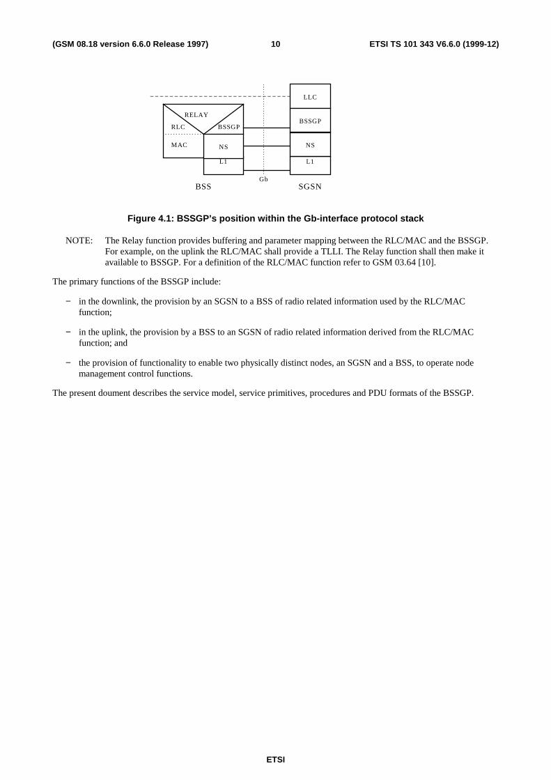
Figure 4.1: BSSGP’s position within the Gb-interface protocol stack
NOTE: The Relay function provides buffering and parameter mapping between the RLC/MAC and the BSSGP.For example, on the uplink the RLC/MAC shall provide a TLLI. The Relay function shall then make itavailable to BSSGP. For a definition of the RLC/MAC function refer to GSM 03.64 [10].
The primary functions of the BSSGP include:
− in the downlink, the provision by an SGSN to a BSS of radio related information used by the RLC/MACfunction;
− in the uplink, the provision by a BSS to an SGSN of radio related information derived from the RLC/MACfunction; and
− the provision of functionality to enable two physically distinct nodes, an SGSN and a BSS, to operate nodemanagement control functions.
The present doument describes the service model, service primitives, procedures and PDU formats of the BSSGP.

ETSI
ETSI TS 101 343 V6.6.0 (1999-12)11(GSM 08.18 version 6.6.0 Release 1997)
5 Elements for layer-to-layer communication
5.1 Definition of service modelIn the present document, the communication between adjacent layers and the services provided by the layers aredistributed by use of abstract service primitives. Only externally observable behaviour resulting from the description isnormatively prescribed by the present document.
The service primitive model used in the present document is based on the concepts developed in CCITTRecommendation X.200 [19].
The service model for a BSS and an SGSN is asymmetric. The service models for a BSS and an SGSN are shownbelow.
GSM 03.64BSSGP
Service model in an SGSN
LLC
BSSGP
Network service
NM
NM
GMM
GMM
BSSGPRLC/MAC
RELAY
Network service
GSM 08.16
NM
NM
GMM
GMM
RL
Service model in a BSS
GSM 08.16
Figure 5.1: BSSGP service model
Primitives consist of commands and their respective responses associated with the services requested of another layer.The general syntax of a primitive is:
− XX - Generic name - Type (Parameters)
where XX designates the layer providing or using the service.
In the present document, XX is:
− “BSSGP” for functions controlling the transfer of LLC frames passed between an SGSN and an MS across theGb interface;
− “RL” (relay) for functions controlling the transfer of LLC frames between the RLC/MAC function and BSSGP;
− “GMM” (GPRS mobility management) for functions associated with mobility management between an SGSNand a BSS; and
− “NM” (network management) for functions associated with Gb-interface and BSS—SGSN node management.

ETSI
ETSI TS 101 343 V6.6.0 (1999-12)12(GSM 08.18 version 6.6.0 Release 1997)
5.2 Service primitives provided by the BSSGP at a BSS
Table 5.2: Service primitives provided by BSSGP at a BSS
Generic name Type ParametersREQuest INDication RESponse CoNFirm
RL� BSSGPRL-DL-UNITDATA - X - - BVCI,
NSEI,Refer to DL-UNITDATAPDU
RL-UL-UNITDATA X - - - BVCI,NSEI,LSP,Refer to UL- UNITDATAPDU
RL-PTM-UNITDATA - X - - BVCI,NSEI,Refer to PTM-UNITDATAPDU
GMM� BSSGPGMM-PAGING - X - - BVCI,
NSEI,Refer to PAGING PS PDURefer to PDU PAGING CSPDU
GMM-RA-CAPABILITY - X - - BVCI,NSEI,Refer to RA-CAPABILITYPDU
GMM-RA-CAPABILITY-UPDATE
X - - X BVCI,NSEI,Refer to RA-CAPABILITY-UPDATE PDU,Refer to RA-CAPABILITY-UPDATE-ACK PDU
GMM-RADIO-STATUS X - - - BVCI,NSEI,Refer to RADIO-STATUSPDU
GMM-SUSPEND X - - X BVCI,NSEI,Refer to SUSPEND PDURefer to SUSPEND-(N)ACK PDU
GMM-RESUME X - - X BVCI,NSEI,Refer to RESUME PDURefer to RESUME-(N)ACKPDU
NM� BSSGPNM-FLUSH-LL - X X - BVCI,
NSEI,Refer to FLUSH-LL PDURefer to FLUSH-LL-ACKPDU
(continued)

ETSI
ETSI TS 101 343 V6.6.0 (1999-12)13(GSM 08.18 version 6.6.0 Release 1997)
Table 5.2 (concluded): Service primitives provided by BSSGP at a BSS
Generic name Type ParametersREQuest INDication RESponse CoNFirm
NM-LLC-DISCARDED X - - - BVCI,NSEI,Refer to LLC-DISCARDEDPDU
NM-FLOW-CONTROL-BVC X - - X BVCI,NSEI,Refer to FLOW-CONTROL-BVC PDURefer to FLOW-CONTROL-BVC ACK PDU
NM-FLOW-CONTROL-MS X - - X BVCI,NSEI,Refer to FLOW-CONTROL-MS PDU Refer to FLOW-CONTROL-MS ACK PDU
NM-STATUS X X - - BVCI,NSEI,Refer to STATUS PDU
NM-BVC-BLOCK X - - X BVCI,NSEI,Refer to BVC-BLOCK PDURefer to BVC-BLOCK-ACKPDU
NM-BVC-UNBLOCK X - - X BVCI,NSEI,Refer to BVC-UNBLOCKPDURefer to BVC-UNBLOCK-ACK PDU
NM-BVC-RESET X X X X BVCI,NSEI,Refer to BVC-RESET PDURefer to BVC-RESET-ACKPDU
NM-TRACE - X - - BVCI,NSEI,Refer to SGSN-INVOKE-TRACE PDU
5.2.1 RL-DL-UNITDATA.ind
Receipt of a DL-UNITDATA PDU from an SGSN by a BSS containing an LLC-PDU and MS control informationnecessary for the transmission of the LLC-PDU across the radio interface.
5.2.2 RL-UL-UNITDATA.req
Request to send a UL-UNITDATA PDU to an SGSN from a BSS containing an LLC-PDU and radio interface derivedinformation.
5.2.3 RL-PTM-UNITDATA.ind
This shall be developed in GPRS phase 2.
5.2.4 GMM-PAGING.ind
Receipt of a PAGING PS or PAGING CS PDU from an SGSN by a BSS containing instructions to page an MS within agiven group of cells.

ETSI
ETSI TS 101 343 V6.6.0 (1999-12)14(GSM 08.18 version 6.6.0 Release 1997)
5.2.5 GMM-RA-CAPABILITY.ind
Receipt of a RA-CAPABILITY PDU from an SGSN by a BSS providing the new Radio Access capability of an MS.
5.2.6 GMM-RA-CAPABILITY-UPDATE.req
Request to send a RA-CAPABILITY-UPDATE PDU to an SGSN from a BSS in order to receive the current RadioAccess capabilities of an MS.
5.2.7 GMM-RA-CAPABILITY-UPDATE.cnf
Receipt of a RA-CAPABILITY-UPDATE-ACK PDU from a SGSN by a BSS containing the current Radio Accesscapabilities of an MS.
5.2.8 GMM-RADIO-STATUS.req
Request to send a RADIO-STATUS PDU to an SGSN from a BSS to report that an exception condition occurred in theoperation of the radio interface for an MS.
5.2.9 GMM-SUSPEND.req
Request to send a SUSPEND PDU to an SGSN from a BSS to mark an MS’s GPRS service as suspended.
5.2.10 GMM-SUSPEND.cnf
Receipt of a SUSPEND-ACK PDU from an SGSN by a BSS confirming that an SGSN has marked an MS’s GPRSservice as suspended.
5.2.11 GMM-RESUME.req
Request to send a RESUME PDU to an SGSN from a BSS to mark an MS’s GPRS service as resumed.
5.2.12 GMM-RESUME.cnf
Receipt of a RESUME-ACK PDU from an SGSN by a BSS confirming that an SGSN has marked an MS’s GPRSservice as resumed.
5.2.13 NM-FLUSH-LL.ind
On receipt of a FLUSH-LL PDU by a BSS from a SGSN, the BSS will either delete queued LLC-PDUs for a TLLI ormove the queued LLC-PDUs from an old to a new BVC.
5.2.14 NM-FLUSH-LL.res
Sending of a FLUSH-LL-ACK PDU to the SGSN from a BSS to report if queued LLC-PDU(s) for an MS were deletedor transferred from the old to the new cell within the NSE.
5.2.15 NM-LLC-DISCARDED.req
Request to send a LLC-DISCARDED PDU to an SGSN from a BSS indicating that LLC frames pertaining to an MShave been locally discarded.
ETSI
ETSI TS 101 343 V6.6.0 (1999-12)15(GSM 08.18 version 6.6.0 Release 1997)
5.2.16 NM-FLOW-CONTROL-BVC.req
Request to send a FLOW-CONTROL PDU to an SGSN from a BSS indicating the ability of a BVC to accept a certainflow of data.
5.2.17 NM-FLOW-CONTROL-BVC.cnf
Confirmation that a FLOW-CONTROL PDU has been received by an SGSN for a given BVC.
5.2.18 NM-FLOW-CONTROL-MS.req
Request to send a FLOW-CONTROL PDU to an SGSN from a BSS indicating the ability to accept a certain flow ofdata for a given MS.
5.2.19 NM-FLOW-CONTROL-MS.cnf
Confirmation that a FLOW-CONTROL PDU has been received by an SGSN for a given MS.
5.2.20 NM-STATUS.req
Request to send a STATUS PDU to an SGSN from a BSS to report that an exception condition occurred within theBSS.
5.2.21 NM-STATUS.ind
Receipt of a STATUS PDU from an SGSN by a BSS indicating that an exception condition occurred within an SGSN.
5.2.22 NM-BVC-BLOCK.req
Request to send a BVC-BLOCK PDU to an SGSN from a BSS to mark a BVC as blocked.
5.2.23 NM-BVC-BLOCK.cnf
Receipt of a BVC-BLOCK-ACK PDU from an SGSN by a BSS confirming that an SGSN has marked a BVC asblocked.
5.2.24 NM-BVC-UNBLOCK.req
Request to send a BVC-UNBLOCK PDU to an SGSN from a BSS to mark a BVC as unblocked.
5.2.25 NM-BVC-UNBLOCK.cnf
Receipt of a BVC-UNBLOCK-ACK PDU from an SGSN by a BSS confirming that an SGSN has marked a BVC asunblocked.
5.2.26 NM-BVC-RESET.req
Request to send a BVC-RESET PDU to an SGSN from a BSS to reset an SGSN’s GPRS BVC contexts.
5.2.27 NM-BVC-RESET.res
Sending of a BVC-RESET-ACK PDU to the SGSN from an BSS indicating that a GPRS BVC context has been reset inthe BSS.

ETSI
ETSI TS 101 343 V6.6.0 (1999-12)16(GSM 08.18 version 6.6.0 Release 1997)
5.2.28 NM-BVC-RESET.ind
Receipt of a BVC-RESET PDU at a BSS from an SGSN indicating that GPRS BVC contexts have been reset at theSGSN.
5.2.29 NM-BVC-RESET.cnf
Receipt of a BVC-RESET-ACK PDU at a BSS confirming that GPRS BVC context has been reset at the SGSN.
5.2.30 NM-TRACE.ind
Receipt of a SGSN-INVOKE-TRACE PDU at a BSS from an SGSN indicating the need to produce a trace record on anMS.

ETSI
ETSI TS 101 343 V6.6.0 (1999-12)17(GSM 08.18 version 6.6.0 Release 1997)
5.3 Service primitives provided by the BSSGP at an SGSN
Table 5.3: Service primitives provided by BSSGP at an SGSN
Generic name Type ParametersREQuest INDication RESponse CoNFirm
LL� BSSGPBSSGP-DL-UNITDATA X - - - BVCI,
NSEI,LSP,Refer to DL-UNITDATAPDU
BSSGP-UL-UNITDATA - X BVCI,NSEI,Refer to UL-UNITDATAPDU
BSSGP-PTM-UNITDATA X - - - BVCI,NSEI,Refer to PTM-UNITDATAPDU
GMM� BSSGPGMM-PAGING X - - - BVCI,
NSEI,Refer to PAGING PS PDURefer to PAGING CS PDU
GMM-RA-CAPABILITY X BVCI,NSEI,Refer to RA-CAPABILITYPDU
GMM-RA-CAPABILITY-UPDATE
- X X - BVCI,NSEI,Refer to RA-CAPABILITY-UPDATE PDU,Refer to RA-CAPABILITY-UPDATE-ACK PDU
GMM-RADIO-STATUS - X - - BVCI,NSEI,Refer to RADIO-STATUSPDU
GMM-SUSPEND - X - - BVCI,NSEI,Refer to SUSPEND PDURefer to SUSPEND-(N)ACK PDU
GMM-RESUME - X - - BVCI,NSEI,Refer to RESUME PDURefer to RESUME-(N)ACKPDU
NM� BSSGPNM-FLUSH-LL X - - X BVCI,
NSEI,Refer to FLUSH-LL PDURefer to FLUSH-LL-ACKPDU
NM-LLC-DISCARDED - X - - BVCI,NSEI,Refer to LLC-DISCARDEDPDU
(continued)

ETSI
ETSI TS 101 343 V6.6.0 (1999-12)18(GSM 08.18 version 6.6.0 Release 1997)
Table 5.3 (concluded): Service primitives provided by BSSGP at an SGSN
Generic name Type ParametersREQuest INDication RESponse CoNFirm
NM-FLOW-CONTROL-BVC - X - - BVCI,NSEI,Refer to FLOW-CONTROL-BVC PDU Refer to FLOW-CONTROL-BVC ACK PDU
NM-FLOW-CONTROL-MS - X - - BVCI,NSEI,Refer to FLOW-CONTROL-MS PDU Refer to FLOW-CONTROL-MS ACK PDU
NM-STATUS X X - - BVCI,NSEI,Refer to STATUS PDU
NM-BVC-BLOCK - X - - BVCI,NSEI,Refer to BVC-BLOCK PDURefer to BVC-BLOCK-ACKPDU
NM-BVC-UNBLOCK - X - - BVCI,NSEI,Refer to BVC-UNBLOCKPDURefer to BVC-UNBLOCK-ACK PDU
NM-BVC-RESET X X X X BVCI,NSEI,Refer to BVC-RESET PDURefer to BVC-RESET-ACKPDU
NM-TRACE X - - - BVCI,NSEI,Refer to SGSN-INVOKE-TRACE PDU
NOTE: The parameters in the BSSGP-DL-UNITDATA and BSSGP-UL-UNITDATA primitives that are notincluded in the corresponding primitives in GSM 04.64 are provided or extracted by some intermediatefunction out of the scope of the present document.
5.3.1 BSSGP-DL-UNITDATA.req
Request to send a DL-UNITDATA PDU to a BSS from an SGSN containing an LLC-PDU and control informationnecessary for the transmission of the LLC-PDU across the radio interface.
5.3.2 BSSGP-UL-UNITDATA.ind
Receipt of a UL-UNITDATA PDU from a BSS by an SGSN containing an LLC-PDU and radio interface derivedinformation.
5.3.3 BSSGP-PTM-UNITDATA.req
This shall be developed in GPRS phase 2.
5.3.4 GMM-PAGING.req
Request to send a PAGING PS or PAGING CS PDU from an SGSN to a BSS containing instructions to page an MSwithin a given group of cells.

ETSI
ETSI TS 101 343 V6.6.0 (1999-12)19(GSM 08.18 version 6.6.0 Release 1997)
5.3.5 GMM-RA-CAPABILITY.req
Request to send a RA-CAPABILITY PDU to the BSS from an SGSN containing the Radio Access capability of an MS.
5.3.6 GMM-RA-CAPABILITY-UPDATE.ind
Receipt of a RA-CAPABILITY-UPDATE PDU from a BSS by an SGSN, requesting that the SGSN sends the RadioAccess capability of an MS to the BSS.
5.3.7 GMM-RA-CAPABILITY-UPDATE.res
Sending of a RA-CAPABILITY-UPDATE-ACK PDU to the BSS from an SGSN containing the current Radio Accesscapability of an MS.
5.3.8 GMM-RADIO-STATUS.ind
Receipt of a RADIO-STATUS PDU from a BSS by an SGSN to report that an exception condition occurred in theoperation of the radio interface for an MS.
5.3.9 GMM-SUSPEND.ind
Receipt of a SUSPEND PDU from a BSS by an SGSN indicating that an MS wishes to suspended its GPRS service.
5.3.10 GMM-RESUME.ind
Receipt of a RESUME PDU from a BSS by an SGSN indicating that an MS wishes to resume its GPRS service.
5.3.11 NM-FLUSH-LL.req
Request to send a FLUSH-LL PDU from an SGSN to a BSS, instructing the BSS to either delete queued LLC-PDUs fora TLLI or move the queued LLC-PDUs from an old to a new BVC.
5.3.12 NM-FLUSH-LL.cnf
Receipt of a FLUSH-LL-ACK PDU at an SGSN informing if the queued LLC-PDU(s) for an MS were deleted ortransferred from the old to the new cell within the NSE.
5.3.13 NM-LLC-DISCARDED.ind
Receipt of a LLC-DISCARDED PDU from a BSS by an SGSN indicating that LLC frames pertaining to an MS havebeen locally discarded.
5.3.14 NM-FLOW-CONTROL-BVC.ind
Receipt of a FLOW-CONTROL PDU from a BSS by an SGSN indicating the ability of a BVC to accept a certain flowof data.
5.3.15 NM-FLOW-CONTROL-MS.ind
Receipt of a FLOW-CONTROL PDU from a BSS by an SGSN indicating the ability to accept a certain flow of data fora given MS.
5.3.16 NM-STATUS.req
Request to send a STATUS PDU to a BSS from an SGSN to report that an exception condition occurred within anSGSN.

ETSI
ETSI TS 101 343 V6.6.0 (1999-12)20(GSM 08.18 version 6.6.0 Release 1997)
5.3.17 NM-STATUS.ind
Receipt of a STATUS PDU from a BSS by an SGSN indicating an exception condition occurred within the BSS.
5.3.18 NM-BVC-BLOCK.ind
Receipt of a BVC-BLOCK PDU from a BSS by an SGSN indicating that a BVC shall be marked as blocked.
5.3.19 NM-BVC-UNBLOCK.ind
Receipt of a BVC-UNBLOCK PDU from a BSS by an SGSN indicating that a BVC shall be marked as unblocked.
5.3.20 NM-BVC-RESET.req
Request to send a BVC-RESET PDU to a BSS from an SGSN to reset a BSS’s GPRS BVC contexts.
5.3.21 NM-BVC-RESET.res
Sending of a BVC-RESET-ACK PDU to the BSS from a SGSN indicating that a GPRS BVC context has been reset inthe SGSN.
5.3.22 NM-BVC-RESET.ind
Receipt of a BVC-RESET PDU at an SGSN from a BSS indicating that GPRS BVC contexts have been reset at theBSS.
5.3.23 NM-BVC-RESET.cnf
Receipt of a BVC-RESET-ACK PDU at an SGSN confirming that GPRS BVC contexts have been reset at the BSS.
5.3.24 NM-TRACE.req
Request to send an SGSN-INVOKE-TRACE PDU to a BSS from an SGSN to begin producing a trace record on an MS.
5.4 Primitive parameters
5.4.1 BSSGP Virtual Connection Identifier (BVCI)
BSSGP Virtual Connections (BVCs) provide communication paths between BSSGP entities. Each BVC is used in thetransport of BSSGP PDUs between peer point-to-point (PTP) functional entities, peer point-to-multipoint (PTM)functional entities and peer signalling functional entities. Table 5.4 lists the mapping of the BSSGP PDU to theassociated functional entity and the BVCI. The BVCI is used to enable the lower network service layer to efficientlyroute the BSSGP PDU to the peer entity. This parameter is not part of the BSSGP PDU across the Gb interface, but isused by the network service entity across the Gb.
Any BSSGP PDU received by the BSS or the SGSN containing a PDU type that does not fit, according to the mappingdefined in table 5.4, with the functional entity identified by the BVCI provided by the network service entity, isdiscarded and a STATUS PDU with a cause value set to “Protocol error - unspecified” is sent.
A PTP functional entity is responsible for PTP user data transmission. There is one PTP functional entity per cell.Within GSM 08.18, a cell is identified by a BVCI unless it is explicitly stated otherwise.
A PTM functional entity is responsible for PTM user data transmission. There is one or more PTM functional entitiesper BSS.
A signalling functional entity is responsible for other functions e.g. paging. There is only one signalling entity perNetwork Service Entity (NSE).There is one or more NSEs per BSS.

ETSI
ETSI TS 101 343 V6.6.0 (1999-12)21(GSM 08.18 version 6.6.0 Release 1997)
Each BVC is identified by means of a BSSGP Virtual Connection Identifier (BVCI) which has end-to-end significanceacross the Gb interface. Each BVCI is unique between two peer Network Service Entities.
In the BSS, it shall be possible to configure BVCIs statically by administrative means, or dynamically. In case ofdynamic configuration, the BSSGP shall accept any BVCI passed by the underlying Network Service entity.
At the SGSN side, BVCIs associated with PTP functional entities shall be dynamically configured. The BVCIsassociated with signalling functional entities and PTM functional entities are statically configured.
The BVCI value 0000 hex shall be used for the signalling functional entities.
The BVCI value 0001 hex shall be used for the PTM functional entities.
All other values may be used freely by the BSS and shall be accepted by the SGSN.
Table 5.4: BSSGP PDU, BVCI and functional entity mapping
BSSGP PDU Mapping of BVCI to functional entity
DL-UNITDATA PTP
UL-UNITDATA PTP
RA-CAPABILITY PTP
PTM-UNITDATA PTM
PAGING-PS PTP or SIGNALLING (NOTE 1)
PAGING-CS PTP or SIGNALLING (NOTE 2)
RA-CAPABILITY-UPDATE / RA-CAPABILITY-UPDATE-ACK
PTP
RADIO-STATUS PTP
SUSPEND / SUSPEND-ACK / SUSPEND-NACK SIGNALLING
RESUME / RESUME-ACK / RESUME-NACK SIGNALLING
FLUSH-LL / FLUSH-LL-ACK SIGNALLING
LLC DISCARDED SIGNALLING
FLOW-CONTROL-BVC / FLOW-CONTROL-BVC-ACK PTP
FLOW-CONTROL-MS / FLOW-CONTROL-MS-ACK PTP
STATUS PTP or PTM or SIGNALLING (NOTE 3)
BVC-BLOCK / BVC-BLOCK-ACK SIGNALLING
BVC-UNBLOCK / BVC-UNBLOCK-ACK SIGNALLING
BVC-RESET / BVC-RESET-ACK SIGNALLING
SGSN-INVOKE-TRACE SIGNALLING
NOTE 1: The network may initiate paging of an MS in READY mobility management state at an indication of alower layer failure (see GSM 04.08 section 4.7.9.1) . In this case, the BVCI=PTP may be used.

ETSI
ETSI TS 101 343 V6.6.0 (1999-12)22(GSM 08.18 version 6.6.0 Release 1997)
NOTE 2 : If the network initiates circuit-switched paging of a MS in READY mobility management state (e.g.a MS in class A or B mode of operation and in packet transfer mode), then the BVCI=PTP. If the MS is
in STANDBY state, then the BVCI=SIGNALLING.
NOTE 3: The setting of the BVCI is dependent upon the context within which the STATUS PDU was generated.
5.4.2 Link Selector Parameter (LSP)
The link selector parameter is defined in GSM 08.16 [16]. At one side of the Gb interface, all BSSGP UNITDATAPDUs related to an MS shall be passed with the same LSP, e.g. the LSP is set to the MS’s TLLI, to the underlyingnetwork service. The LSPs used at the BSS and SGSN for the same MS may be set to different values.
5.4.3 [functional-name] PDU
The parameters that make up a [functional-name] PDU are defined in PDU Functional Definitions and contents/GSM08.18.
5.4.4 Network Service Entity Identifier (NSEI)
The Network Service Entity at the BSS and the SGSN provides the network management functionality required for theoperation of the Gb interface. The Network Service Entity is described in GSM 08.16.
Each Network Service Entity is identified by means of a Network Service Entity Identifier (NSEI). The NSEI togetherwith the BVCI uniquely identifies a BSGP Virtual Connection (e.g. a PTP functional entity) within an SGSN. The NSEIis used by the BSS and the SGSN to determine the NS-VCs that provides service to a BVCI.
6 User data and signalling procedures between RL andBSSGP SAPs
6.1 Downlink UNITDATA procedureOn the downlink, a DL-UNITDATA PDU shall contain information elements to be used by the RLC/MAC function andan LLC-PDU. There shall be only one LLC-PDU per DL-UNITDATA PDU. The LLC-PDU shall always be the lastinformation element in the DL-UNITDATA PDU, and shall be aligned on a 32 bit boundary for efficient processing.
An SGSN provides the BSSGP with a current TLLI, identifying the MS. If an SGSN provides a second TLLI, indicatingthat an MS has recently changed its TLLI, this shall be considered as the “old” TLLI. A BSS uses the “old” TLLI tolocate an MS’s existing context. Subsequent uplink data transfers for this MS shall reference the current TLLI, and notthe old TLLI.
If the SGSN has a valid IMSI for a TLLI, then the SGSN shall include it in the PDU. If the SGSN has valid DRXParameters for a TLLI, then the SGSN shall include them in the PDU. Nevertheless, the SGSN can omit the DRXParameters during a DRX forbidden period (see GSM 04.60 []) to speed up the transmission of the LLC-PDU on theradio interface.
An SGSN provides the BSSGP with MS specific information, enabling the RLC/MAC entity in a BSS to transmit anLLC-PDU to the MS in a user specific manner. The information made available to the radio interface includes:
− MS Radio Access Capability. This defines the radio capabilities of the ME. If there is valid MS Radio AccessCapability information known by the SGSN for the associated MS, the SGSN shall include it in the DL-UNITDATA PDU. Otherwise, MS Radio Access Capability shall not be present.
− QoS Profile. This defines the (peak) bit rate, the type of BSSGP’s SDU (signalling or data), the type of LLCframe (ACK, SACK, or not), the precedence class, and the transmission mode to be used when transmitting theLLC-PDU across the radio interface.
ETSI
ETSI TS 101 343 V6.6.0 (1999-12)23(GSM 08.18 version 6.6.0 Release 1997)
− PDU Lifetime. This defines the remaining time period that the PDU is considered as valid within the BSS. If thePDU is held for a period exceeding the “PDU Lifetime” time period, the PDU shall be locally discarded. ThePDU Lifetime is set within the SGSN by the upper layers.
A BSS may incorporate the PDU Lifetime, the Precedence and the (peak) bit rate into its radio resource scheduler. Thealgorithm to do this is out of scope of the present document.
Two types of BSSGP SDU are distinguished within the QoS Profile : layer 3 signalling and data. Layer 3 signalling maybe transmitted over the Um interface with higher protection.
The type of LLC frame indicates if the LLC frame type is an ACK or SACK command/response, or not (see GSM04.64). An ACK or SACK command/response frame type may be transmitted over the Um interface with higher priority.
Two transmission modes across the radio interface are possible; acknowledged (using RLC/MAC ARQ functionality)and unacknowledged (using RLC/MAC unitdata functionality).
If Priority is present, only the priority-level field shall be regarded. The management of priority levels is implementationdependent and under operator control. The preemption capability indicator, the queuing allowed indicator andpreemption vulnerability indicator shall be ignored.
In addition to constructing the DL-UNITDATA, the SGSN supplies the LSP, the BVCI and the NSEI associated withthe MS to the lower layer network service, enabling network service routeing to the peer entity. These parameters arenot transmitted as part of the BSSGP across the Gb-interface.
6.1.1 Abnormal conditions
The following actions are defined in periods of congestion.
To satisfy the maximum number of service requests, the BSS may redistribute MSs among cells (i.e. network controlledcell reselection is initiated). If this occurs, the BSS may inform the SGSN through the RADIO STATUS PDU (RadioCause value: cell reselection ordered). The BSS shall update any internal references that indicate the location of the MS.The BSS may attempt to internally re-route queued LLC frames to an MS that has been moved to a new cell. If thisfunctionality is not supported, or if it is not possible to internally re-route LLC frames, the LLC frame shall bediscarded.
It is the responsibility of the higher layer protocols in the SGSN to cope with discarded LLC frames.
6.2 Uplink UNITDATA procedureOn the uplink, a UL-UNITDATA PDU shall contain information elements derived from the RLC/MAC function,meaningful to higher-layer protocols in an SGSN, and an LLC-PDU. There shall be only one LLC-PDU per UL-UNITDATA PDU. The LLC-PDU shall always be the last information element in the UL-UNITDATA PDU, and shallbe aligned on a 32 bit boundary for efficient processing.
The BSS shall provide the TLLI, received from the MS, to the SGSN.
The BSS shall provide a BVCI and an NSEI indicating the PTP functional entity (i.e. the cell) upon which the LLC-PDU was received. The SGSN shall obtain the BVCI and the NSEI from the underlying network service; the BVCI andthe NSEI are not visible in the UL-UNITDATA PDU.
The BSS provides the SGSN with the QoS Profile used in the LLC-PDU’s transmission from the mobile station acrossthe radio interface.
− QoS Profile. This reports the (peak) bit rate, the precedence used at radio access and the transmission mode usedacross the radio path. The type of the BSSGP SDU, layer 3 signalling or data, and the type of LLC frame,SACK, ACK, or not, are not meaningful on the uplink and shall be ignored.
In order to support location based services, the BSS shall include the cell identifier of the cell upon which the LLC-PDUwas received.
ETSI
ETSI TS 101 343 V6.6.0 (1999-12)24(GSM 08.18 version 6.6.0 Release 1997)
In addition to constructing the UL-UNITDATA, the BSS supplies the LSP, the NSEI and the BVCI associated with theMS to the lower layer network service, enabling network service routeing to the peer entity. These parameters are nottransmitted as part of the BSSGP across the Gb-interface.
6.2.1 Abnormal conditions
None specified.
6.3 RA-CAPABILITY procedureThe SGSN stores an MS’s current radio access capability (which may be changed by higher layer mobility managementprocedures). An MS’s current radio access capability, and the TLLI identifying the MS, are conveyed to a BSS in a RA-CAPABILITY PDU. The received MS’s radio access capability, if valid, shall then replace any radio access capabilitypreviously associated with the MS.
6.3.1 Abnormal conditions
If the BSS receives an unknown Access Technology Type in the MS Radio Access Capability field, it shall ignore thefields associated with that Access Technology type.
If the BSS receives unknown fields within a known Access Technology Type in the MS Radio Access Capability field,it shall ignore the unknown fields.
7 Signalling procedures between GMM SAPs
7.1 Paging procedureWhen an SGSN initiates the paging procedure for GPRS services as defined in GSM 04.08 [11], it shall send one ormore PAGING-PS PDUs to the BSS.
When instructed by an MSC/VLR to initiate a paging procedure for non-GPRS services as defined in GSM 04.08 [11],an SGSN shall send one or more PAGING-CS PDUs to the BSS.
These paging PDUs shall contain the information elements necessary for the BSS to initiate paging for an MS within agroup of cells.
The SGSN provides an indication of the cells within which the BSS shall page the MS. The levels of resolution withinone BSS are : all cells within the BSS, all cells on the BSS within one location area, all cells on the BSS within onerouting area, and one BVCI (i.e. cell). A routing area, a location area, or a BSS area is associated with one or moreNSEIs. If the cells in which to page the MS are served by several NSEIs then one paging PDU must be sent to each ofthese NSEIs.
A paging PDU shall be used to generate the corresponding radio interface paging request message(s) to be transmitted atthe appropriate time.
It should be noted that each paging PDU relates to only one MS and therefore a BSS may pack pages for different MSsinto the relevant GSM 04.08 [11] or GSM 04.60 [] radio interface paging request messages.
In the case of paging for non-GPRS services, the SGSN shall provide the MS’s IMSI and DRX Parameters.
In the case of paging for GPRS services, the SGSN shall provide the MS’s IMSI. If DRX Parameters are available, theSGSN shall also provide the DRX Parameters.
NOTE: The IMSI and the DRX Parameters enable the BSS to derive the paging population number. Pagingwithout DRX parameters may require a considerable extension of the paging duration.
An SGSN provides the BSSGP with MS specific information, enabling a BSS to execute the paging procedure in an MSspecific manner. This includes:

ETSI
ETSI TS 101 343 V6.6.0 (1999-12)25(GSM 08.18 version 6.6.0 Release 1997)
− QoS Profile. The Precedence parameter is set by the upper layers [in the SGSN]. The SGSN shall set the bit rateparameter to “best effort”. The SGSN shall set the transmission mode to unacknowledged. The BSS shall ignorethe received bit rate, the BSSGP SDU type, LLC type, and transmission mode parameters.
If an SGSN provides a P-TMSI in a PAGING-PS PDU, then the BSS shall use the P-TMSI to address the MS. If theSGSN does not provide the P-TMSI in the PAGING-PS PDU, then the BSS shall use the IMSI to address the MS.Therefore, the SGSN shall not provide the P-TMSI if it wants to page the MS with the IMSI.
If an SGSN provides a TLLI in a PAGING-CS PDU and a radio context identified by the TLLI exists within the BSS,then the paging request message shall be directly sent to the MS. If the SGSN does not provide the TLLI in thePAGING-CS PDU or if no radio context identified by the TLLI exists within the BSS, then the BSS shall use the TMSI,if provided in the PAGING-CS PDU, else the IMSI, to address the MS.
The PAGING-CS PDU consists of the parameters described above for a PAGING-PS PDU (except the P-TMSI andQoS profile parameters) and, optionally, some or all of the following parameters; TMSI, TLLI, Channel Needed andeMLPP-Priority. The Channel Needed and eMLPP-Priority information shall be handled transparently by the BSS.
7.2 Radio Access Capability Update procedureThe BSS may request an MS’s current Radio Access capability by sending to an SGSN a RA-CAPABILITY-UPDATEPDU which includes the TLLI of the MS and a Tag. The allocation of the Tag is implementation specific. The BSS thenstarts timer T5.
The SGSN shall respond by sending a RA-CAPABILITY-UPDATE-ACK PDU which includes the TLLI of the MS, theTag received in the corresponding RA-CAPABILITY-UPDATE PDU, and an RA-Cap-UPD-Cause field. The BSS shallstop timer T5.
If the RA-Cap-UPD-Cause is set to "OK", then a MS Radio Access Capability field shall be present. The received MS’sradio access capability, if valid, shall then replace any radio access capability previously associated with the MS. If theRA-Cap-UPD-Cause is not set to "OK", then the MS Radio Access Capability shall not be present in the RA-CAPABILITY-UPDATE-ACK PDU.
7.2.1 Abnormal conditions
If an SGSN receives a RA-CAPABILITY-UPDATE PDU which includes an unknown TLLI, it shall answer with a RA-CAPABILITY-UPDATE-ACK PDU which includes the RA-CAP-UPD-Cause set to the value "TLLI unknown".
If an SGSN receives a RA-CAPABILITY-UPDATE PDU which includes a known TLLI, but there are no Radio Accessparameters known to the SGSN for the associated MS, the SGSN shall reply to the request with a RA-CAPABILITY-UPDATE-ACK PDU in which the RA-CAP-UPD-Cause is set to: "no RA capability available".
If a BSS receives a RA-CAPABILITY-UPDATE-ACK PDU containing a Tag which is different from the lasttransmitted Tag by the BSS, it shall ignore the reception of this PDU.
If a BSS sends a RA-CAPABILITY-UPDATE PDU to an SGSN and the RA-CAPABILITY-UPDATE-ACK is notreturned within a period T5 with the same Tag value as provided in the request, the RA-CAPABILITY-UPDATEprocedure shall be repeated a maximum of RA-CAPABILITY-UPDATE-RETRIES attempts. The Tag value shall bechanged by the BSS at each new retry.
7.3 Radio Status procedureA BSS and an MS radio interface communication may not be successfully completed as requested because:
1) the MS goes out of coverage and is lost;
This condition is signalled by setting the Radio Cause value to “Radio contact lost with MS”.
2) the link quality is too bad to continue the communication;

ETSI
ETSI TS 101 343 V6.6.0 (1999-12)26(GSM 08.18 version 6.6.0 Release 1997)
This condition is signalled by setting the Radio Cause value to “Radio link quality insufficient to continuecommunication”.
3) the BSS has ordered the MS to perform a cell-reselection.
This condition is signalled by setting the Radio Cause value to “cell-reselection ordered”.
Conditions 1) and 2) indicate that attempts to communicate between an MS and an SGSN via this cell should besuspended or abandoned. An SGSN shall stop sending LLC-PDUs to the cell for the MS. The criteria for decidingwhether condition 1) or 2) has occurred is not in the scope of GSM 08.18.
The conditions for resuming a suspended or abandoned communication between an MS and SGSN are defined in GSM04.08 [11].
Condition 3) indicates that the SGSN should wait for a cell update before resuming the transmission of LLC-PDUs tothe BSS.
A BSS shall signal these exception conditions to an SGSN by sending a RADIO-STATUS PDU. It shall contain areference to the MS, either TLLI or TMSI or IMSI, and an indication of the exception condition, i.e. the Radio Causevalue.
7.4 SUSPEND procedureIf the MS signals to the BSS that it wishes its GPRS service to be suspended, the BSS shall send a SUSPEND PDU tothe SGSN and start timer T3. Actions within the SGSN while an MS is suspend are not specified, but paging is typicallystopped. The SUSPEND PDU contains:
− the TLLI of the MS; and
− the Routeing Area of the MS.
For each SUSPEND PDU received by an SGSN, a SUSPEND-ACK PDU shall be returned to the BSS. Upon receptionof the SUSPEND-ACK PDU, the BSS shall stop T3. The SUSPEND-ACK PDU contains:
− the TLLI of the MS;
− the Routeing Area of the MS; and
− the Suspend Reference Number.
The SGSN generates the Suspend Reference Number in a manner that it enables it to differentiate between differentSUSPEND PDUs relating to the same MS.
7.4.1 Abnormal conditions
If a SUSPEND-ACK PDU is not received for a SUSPEND PDU within T3 seconds, then the SUSPEND PDUprocedure shall be repeated a maximum of SUSPEND-RETRIES attempts. After SUSPEND-RETRIES attempts theprocedure is stopped and the O&M system is informed.
If a SUSPEND-ACK PDU is received for an MS that is already marked as suspended, then the SUSPEND-ACK PDU isignored.
If a SUSPEND PDU refers to an MS which is unknown in the SGSN, then a SUSPEND-NACK PDU is returnedcontaining a cause value (Cause value: Unknown MS). The BSS shall stop the SUSPEND procedure.
7.5 RESUME procedureWhen a GPRS-attached MS leaves dedicated mode, disconnecting the MS from the MSC, the BSS shall either a)instruct the MS to initiate the Routeing Area Update procedure, or b) signal to the SGSN that an MS’s GPRS serviceshall be resumed.

ETSI
ETSI TS 101 343 V6.6.0 (1999-12)27(GSM 08.18 version 6.6.0 Release 1997)
If the BSS executes a), then no further action is required.
If the BSS executes b), then the BSS shall send a RESUME PDU containing the same Suspend Reference Numberreceived in the SUSPEND-ACK PDU to the SGSN and start timer T4. The RESUME PDU contains:
− the TLLI of the MS;
− the Routeing Area of the MS; and
− the Suspend Reference Number.
For each RESUME PDU received by an SGSN, a RESUME-ACK PDU shall be returned to the BSS. Upon reception ofthe RESUME-ACK PDU, the BSS shall stop T4. The RESUME-ACK PDU contains:
− the TLLI of the MS; and
− the Routeing Area of the MS.
7.5.1 Abnormal conditions
If a RESUME-ACK PDU is not received for a RESUME PDU within T4 seconds, then the RESUME PDU procedureshall be repeated a maximum of RESUME-RETRIES attempts. After RESUME-RETRIES attempts the procedure isstopped, the O&M system is informed and the MS shall be instructed to initiate the Routeing Area Update procedure.
If a RESUME-ACK PDU is received for an MS that is not suspended, then the RESUME-ACK PDU is ignored.
If a RESUME PDU refers to an MS which is unkown in the SGSN, then a RESUME-NACK PDU is returned containinga cause value (Cause value: Unknown MS). The BSS shall stop the RESUME procedure and the MS shall be instructedto initiate the Routeing Area Update procedure.
8 Signalling procedures between NM SAPs
8.1 FLUSH-LL (logical link) procedureWhen an SGSN detects a cell change of an MS from a cell update or a routing area update, the SGSN shall send aFLUSH-LL PDU to the old BVC to initiate the following procedures:
− At a cell change within one NSE (e.g. the BSS is a NSE) and within one routing area, LLC-PDU(s) for a givenTLLI stored at an “old” BVCI (corresponding to the old cell) are either deleted or transferred to a “new” BVCI(corresponding to the new cell) with which the TLLI is currently associated; or
− At a cell change between two NSEs or between two routing areas, LLC-PDU(s) stored at the “old” BVCI for theTLLI are deleted.
The SGSN provides the BSSGP with:
− a MS´s TLLI identifying the MS;
− the ”old” BVCI identifying the cell in which to find buffered LLC-PDU(s) for the MS; and
− the “new” BVCI identifying the cell to which the MS is currently associated (only when within the same NSE andwithin the same routing area).
If a “new” BVCI is not provided, then the FLUSH-LL PDU shall be interpreted as an instruction to delete the queuedLLC-PDU(s) at the old BVC.
Queued BSSGP signalling, e.g. pages, shall not be affected by this procedure.
In response to a FLUSH-LL PDU the BSS shall send a FLUSH-LL-ACK PDU to the SGSN containing:
− the TLLI received in the FLUSH-LL PDU; and

ETSI
ETSI TS 101 343 V6.6.0 (1999-12)28(GSM 08.18 version 6.6.0 Release 1997)
− an indication of whether the LLC-PDU(s) were “transferred” (when in the same NSE) or “deleted”. In case theSDUs were "transferred" the BVCI (new) IE shall be included.
On receipt of a FLUSH-LL-ACK PDU by the SGSN, indicating that the LLC-PDU(s) associated with the old BVC havebeen “deleted”, the SGSN may choose to:
− immediately re-transmit all un-acknowledged LLC-PDU(s) (in acknowledged LLC operation) to the MS at thenew BVC (ie new cell); or
− relay on LLC retransmission mechanism to transmit un-acknowledged LLC-PDU(s).
On receipt of a FLUSH-LL-ACK PDU by the SGSN, indicating that the LLC-PDU(s) associated with the old BVC havebeen “transferred” within the NSE, the SGSN shall not take any of the above actions.
8.1.1 Abnormal Conditions
If the BSS receives a FLUSH-LL PDU for an unknown BVCI or TLLI not associated with the given BVCI, then theFLUSH-LL PDU is discarded and no FLUSH-LL-ACK PDU is returned.
If the SGSN does not receive a FLUSH-LL-ACK PDU in response to a FLUSH-LL PDU, no further action is taken.
8.2 Flow Control procedure
8.2.1 General model of operation
From the perspective of the BSSGP, the flow control mechanism is based on the following model:
− There is a downlink buffer for each BVC, as identified by a BVCI, in a BSS;
− The transfer of BSSGP UNITDATA PDUs for an MS from the SGSN is controlled by the BSS; and
− Only downlink BSSGP UNITDATA PDU transfer to the BSS is managed via flow control procedures. Uplinkflow control is not performed.
8.2.2 Mode of operation
The flow control mechanism manages the transfer of BSSGP UNITDATA PDUs sent by the SGSN on the Gb interfaceto the BSS.
The BSS shall control the flow of BSSGP UNITDATA PDUs to its BVC buffers by indicating to the SGSN themaximum allowed throughput in total for each BVC. The BSS shall control the flow of BSSGP UNITDATA PDUs tothe BVC buffer for an individual MS by indicating to the SGSN the maximum allowed throughput for a certain TLLI.
The BSS uses flow control to adjust the flow of BSSGP UNITDATA PDUs to a BVC buffer. The amount of bufferedBSSGP UNITDATA PDUs in the BSS should be optimised to efficiently use the available radio resource. The volumeof buffered BSSGP UNITDATA PDUs for a BVC or MS should be low. BSSGP UNITDATA PDUs queued within theBSS that are not transferred across the radio interface before the PDU Lifetime expires shall be locally deleted from theBSS. The local deletion of BSSGP UNITDATA PDUs in the BSS shall be signalled to the SGSN by the transmission ofa LLC-DISCARDED PDU.
For each FLOW-CONTROL PDU received by an SGSN, a confirmation shall always be sent across the Gb interface bythe SGSN. The confirmation uses the Tag that was received in the FLOW-CONTROL PDU, which was set by the BSSto associate the response with the request. When receiving no confirmation to a FLOW-CONTROL PDU, the reasonsthat gave rise to the triggering of a flow control message may trigger another message, or, if the condition disappears, itmay not. For the repetition of non-confirmed FLOW CONTROL PDUs, the maximum repetition rate still applies in theBSS.

ETSI
ETSI TS 101 343 V6.6.0 (1999-12)29(GSM 08.18 version 6.6.0 Release 1997)
8.2.3 Flow Control of Traffic from an SGSN to BSS
8.2.3.1 Control of the downlink throughput by the SGSN
The principle of the BSSGP flow control procedures is that the BSS sends to the SGSN flow control parameters whichallow the SGSN to locally control its transmission output in the SGSN to BSS direction. The SGSN shall perform flowcontrol on each BVC and on each MS. The flow control is performed on each LLC-PDU first by the MS flow controlmechanism and then by the BVC flow control mechanism. If the LLC-PDU is passed by the individual MS flow control,the SGSN then applies the BVC flow control to the LLC-PDU. If an LLC-PDU is passed by both flow controlmechanisms, the entire LLC-PDU is delivered to the Network Services for transmission to the BSS (see Figure 8.1).
MS Flow control MS Flow control MS Flow control
BVC Flow control
BSS
Figure 8.1: BVC Flow control
The flow control parameters sent by the BSS to the SGSN consist of the following information :
− the bucket size (Bmax) for a given BVC or MS in the downlink direction; and
− the bucket leak rate (R) for a given BVC or MS in the downlink direction.
The SGSN shall perform flow control on an individual MS using SGSN determined values of Bmax and R unless itreceives a FLOW-CONTROL-MS message from the BSS regarding that MS. The SGSN shall continue to perform flowcontrol for a particular MS using the Bmax and R values received from the BSS for at least Th seconds after receiving aFLOW-CONTROL-MS message from the BSS regarding that MS. When timer Th has expired or when the MS changescells, the SGSN may reinitialise the SGSN internal flow control variables for that MS and begin to use SGSN generatedvalues for Bmax and R.
The BSSGP flow control model is the algorithm shown in Figure 8.2. The model of the algorithm is that an LLC-PDU ispassed by the algorithm as long as the bucket counter (B) plus the length of the LLC-PDU does not exceed the bucketsize Bmax. When the LLC-PDU is passed, the LLC-PDU length is added to B. Any PDU not transmitted is delayed untilB plus the LLC-PDU length is less than Bmax.
8.2.3.2 Flow Control Conformance Definition
A BSSGP flow control algorithm shall be implemented in the SGSN. The BSSGP flow control conformance algorithmis defined in Figure 8.2.
The conformance definition is used to decide which LLC-PDUs are conforming to the flow to an MS or in a BSSGPvirtual connection (BVC) over the Gb interface. The conformance definition should not be interpreted as the requiredimplementation algorithm, as the SGSN manufacturer may use any algorithm as long as the operation of the BSSGPflow control does not violate the objectives of compliant BVCs or MSs. That is, the SGSN shall never transmit moredata than can be accommodated within the BSS buffer for a BVC or individual MS.

ETSI
ETSI TS 101 343 V6.6.0 (1999-12)30(GSM 08.18 version 6.6.0 Release 1997)
Arrival of LLC PDU p withlength L(p) at time Tc
B* < L(p)?B* = B + L(p) – (Tc - Tp) x R
B = L(p)
B = B*B* > Bmax?
yes
yes
no
no
Delay LLC PDU Pass LLC PDU
Tp = Tc
Figure 8.2: Conformance Definition Algorithm for BSSGP Flow Control
The variables used by the algorithm are:
− Bmax Bucket Size. Set by the BSS for each cell and each mobile station. Bmax shall be large enough toaccommodate at least one LLC-PDU;
− R leak rate of the bucket;
− B bucket counter;
− B* predicted value of the bucket counter;
− L(p) length of LLC-PDU p;
− Tp the time that the last LLC-PDU p was transferred; and
− Tc arrival time of LLC-PDU p.
The initial conditions of these variables in the SGSN are:
− Bmax= 0. For BVCs, this value is valid until Bmax is received in the Flow Control-BVC. For MSs, this value isvalid until Bmax_default_ MS is received in the Flow-Control-BVC message. Thereafter, subclause “Condition ofBmax for MS after Initial Flow-Control-BVC”, shall apply;
− R = 0. For a BVC, this value is valid until a Flow-Control-BVC message is received. For an MS, this value isvalid until a Flow-Control-BVC message is received. Thereafter, subclause “Condition of Bmax for MS after InitialFlow-Control-BVC”, shall apply;
− B = 0 (the bucket is empty); and− Tp = the current time for the first LLC-PDU.
The SGSN shall not transmit a LLC-PDU on a BVC until a Flow-Control-BVC message is received from the BSS forthat BVC.
When a LLC-PDU p arrives at current time Tc, the variable B* is set to the predicted bucket size if the LLC-PDU wereto be transferred to the BSS. This is given by the previous bucket size plus the new LLC-PDU size, B* = B + L(p), lessthe amount that the bucket will have leaked away since the last compliant LLC-PDU, R * (Tc - Tp). If this is less thanL(p) then the LLC-PDU is compliant and the bucket size B is reset to L(p) and the LLC-PDU is passed. When acompliant LLC-PDU is passed the last LLC-PDU transfer time is set to the current time, Tp = Tc.

ETSI
ETSI TS 101 343 V6.6.0 (1999-12)31(GSM 08.18 version 6.6.0 Release 1997)
If the bucket has not completely leaked away then the bucket has to be checked to see if the limit Bmax is going to beexceeded, B* > Bmax. If the limit is exceeded then the LLC-PDU is non compliant and is delayed for some time period,and no updates are done on the variables. If the bucket limit Bmax is not exceeded then the LLC-PDU is compliant andthe bucket counter (B) is set equal to the value of B*. When a conforming LLC-PDU is passed then the last LLC-PDUtransfer time is set to the current time, Tp = Tc.
On receipt of a FLUSH-LL-ACK PDU by the SGSN, indicating that the LLC-PDU(s) associated with the old BVC havebeen “deleted”, the SGSN should update the value of the bucket counter (B) for the MS and for the old BVC, B = max (B - N , 0 ). N is provided by FLUSH-LL-ACK PDU, indicating the number of octets deleted by the BSS.
On receipt of a FLUSH-LL-ACK PDU by the SGSN, indicating that the LLC-PDU(s) associated with the old BVC havebeen “transferred” within the NSE, the SGSN should update the value of the bucket counter (B) for the old BVC, B =max ( B - N , 0 ). The value of B for the new BVC should also be updated, B = min ( B + N, Bmax ). N is provided byFLUSH-LL-ACK PDU, indicating the number of octets transferred by the BSS.
On receipt of a LLC-DISCARDED PDU by the SGSN, indicating that the LLC-PDU(s) associated with the MS havebeen locally deleted by the BSS, the SGSN should update the value of the bucket counter (B) for the MS and for theBVC, B = max ( B - N , 0 ). N is provided by LLC-DISCARDED PDU, indicating the number of octets deleted by theBSS.
The BSS may update the values of Bmax and R within the SGSN at any time by transmitting a new Flow Control PDUcontaining the new Bmax and R values. The variables B, B*, Tp and Tc are local to the SGSN and are not affected bythe reception of a Flow-Control-BVC or Flow Control-MS PDU.
8.2.3.3 Response time within the SGSN to flow control messages
Upon reception of flow control requests from a BSS, the SGSN shall modify its downlink transmission as instructedwithin 100ms.
8.2.3.4 Frequency of sending BVC or MS Flow Control PDUs
The rate at which the BSS is allowed to send flow control messages for a given BVC or MS is limited and defined bythe following rule: the BSS may send a new Flow Control PDU every C seconds, where C is a value which is pre-defined and common to the BSS and SGSN.
If the BSS detects a missing FLOW-CONTROL-ACK from the SGSN and the condition which causes the sending of aFLOW-CONTROL PDU still remains, the FLOW-CONTROL PDU may be retransmitted immediately. In this case theBSS may violate the repetition rate defined by the C value.
8.2.3.5 FLOW-CONTROL PDUs
Based on the criteria for flow control, a BSS shall send to an SGSN a FLOW-CONTROL PDU containing a list of IEs.
For BVC Flow Control, the following information is sent:
− The maximum bucket size (Bmax) for the BVC on the Gb Interface;
− The leak rate parameter (R) to be applied to the bucket;
− The default MS bucket size (Bmax_default_MS);
− The default MS leak rate (R_default_MS); and
− The optional measurement of the delay for PDU delivery inside that BVC.
For MS Flow Control, the following information is sent:
− The TLLI identifying the MS;
− The maximum bucket size (Bmax) for this MS on the Gb interface; and
− The leak rate parameter (R) to be applied to the bucket.

ETSI
ETSI TS 101 343 V6.6.0 (1999-12)32(GSM 08.18 version 6.6.0 Release 1997)
8.2.3.6 Condition of Bmax for MS after Initial Flow-Control-BVC
The SGSN may use the following (informative) equation to generate an initial bucket size, Bmax, for an MS.
Bmax (bits) = min (R_default_MS for 1 sec, 72000, max MS throughput for 1 sec, (max MS throughput for1sec + current throughput of all other MSs in the cell for 1 sec) / number of MSs in the cell)
where, the number of MSs in the cell includes the MS being added.
Under no circumstance shall the SGSN use a value of Bmax greater than Bmax_default_MS for an MS unless it receivesa Flow-Control-MS message from the BSS for that MS.
The SGSN shall not use a leak rate (R) for an MS greater than R_default_MS unless it receives a Flow-Control-MSmessage from the BSS for that MS.
8.2.4 Flow Control of Uplink Traffic from a BSS to an SGSN
No flow control procedures are defined between the BSS and the SGSN in uplink direction.
8.3 BVC blocking and unblocking procedure
8.3.1 PTP BVC
The following statement applies only for PTP BVC.
The BVC blocking and unblocking procedures are initiated by the BSS to remove from use, or bring in to use, a BVC.
A BSS may block one BVC because of:
− Operation and Maintenance intervention for a cell;
− equipment failure at the BSS;
− cell equipment failure at the BSS; or
− other causes not regarded in phase 1 of the implementation of GPRS (Cause Value: “reserved for future use”).
When a BSS wishes to block a BVC, the BSS shall mark that BVC as blocked, thereafter discarding any traffic sent tothe BVC in the uplink direction. The cell associated with the BVC should not accept data in the downlink direction. TheBSS shall send a BVC-BLOCK PDU to the SGSN and start timer T1.The BVC-BLOCK PDU contains:
− the BVCI of the BVC to be blocked; and
− a Cause element indicating the reason for blocking (typical cause values: O&M intervention, Equipment failure).
On receipt of a BVC-BLOCK PDU, the SGSN shall mark the indicated BVC as blocked and stop transmitting trafficaddressed to this BVC. The SGSN shall then acknowledge the blocking of the BVC by sending a BVC-BLOCK-ACKPDU to the BSS.
The BVC-BLOCK-ACK PDU contains the BVCI received in the BVC-BLOCK PDU.
On receipt of the BVC-BLOCK-ACK PDU the BSS shall stop timer T1.
The BVC shall be seen as blocked by an SGSN until a BVC-UNBLOCK PDU is received indicating that the BVC’sstatus has changed.
During the BVC blocking procedure, traffic in transit to or from a cell is in an indetermined state and may be lost. Whenunblocking a BVC both the BSS and SGSN shall be in an operational state, i.e. the underlying network service and theBVC shall be available for use.
If a BSS wishes to unblock a blocked BVC it shall send a BVC-UNBLOCK PDU, and start timer T1.

ETSI
ETSI TS 101 343 V6.6.0 (1999-12)33(GSM 08.18 version 6.6.0 Release 1997)
The BVC-UNBLOCK PDU contains:
− the BVCI of the BVC to be unblocked.
If a BVC-UNBLOCK PDU is received by an SGSN for a blocked BVC, the BVC shall be marked as unblocked and aBVC-UNBLOCK-ACK PDU shall be returned to the BSS, containing the BVCI received in the BVC-UNBLOCK PDU.
The BSS shall stop timer T1 on receipt of the BVC-UNBLOCK-ACK PDU and mark the BVC as unblocked.
8.3.2 Signalling BVC
The blocking and unblocking procedure is not applicable for the signalling BVC. The signalling BVC shall never beblocked.
8.3.3 Abnormal Conditions
The following statements apply only for a signalling BVC
If a BVC-BLOCK PDU is received by an SGSN for the signalling BVC, the PDU is ignored.
If a BVC-BLOCK-ACK PDU is received by a BSS for the signalling BVC, the PDU is ignored.
If BVC-UNBLOCK PDU is received by an SGSN for the signalling BVC, the PDU is ignored
If BVC-UNBLOCK-ACK PDU is received by an BSS for the signalling BVC, the PDU is ignored.
The following statements apply only for PTP BVC.
If a BVC-BLOCK-ACK PDU is not received for a BVC-BLOCK PDU within T1 seconds, then the BVC-BLOCK PDUprocedure shall be repeated a maximum of BVC-BLOCK-RETRIES attempts. After BVC-BLOCK-RETRIES attemptsthe BVC remains blocked, the procedure is stopped and the O&M system is informed.
If a BVC-UNBLOCK-ACK PDU is not received for a BVC-UNBLOCK PDU within T1 seconds, then the BVC-UNBLOCK PDU procedure shall be repeated a maximum of BVC-UNBLOCK-RETRIES attempts. After BVC-UNBLOCK-RETRIES attempts the status of the BVC remains blocked, the procedure is stopped and the O&M systemis informed.
If traffic is received on a BVC that is marked at a BSS or at an SGSN as blocked, and no BVC-Unblocking procedure ispending, the received PDU shall not be accepted and a STATUS PDU (Cause value: BVC blocked) shall be sent to thepeer entity on the signalling BVC. The STATUS PDU shall indicate the BVCI of the BVC upon which the error wasdetected.
If a BVC-BLOCK PDU is received by an SGSN for a blocked BVC, a BVC-BLOCK-ACK PDU shall be returned.
If a BVC-UNBLOCK PDU is received by an SGSN for an unblocked BVC, a BVC-UNBLOCK-ACK PDU shall bereturned.
If an unexpected BVC-BLOCK-ACK PDU is received by a BSS, and it is related to a BVC that is locally blocked, theBVC-BLOCK-ACK PDU is discarded. If the BVC-BLOCK-ACK PDU is related to a BVC that is not locally blocked,then a BVC unblock procedure shall be performed.
If an unexpected BVC-UNBLOCK-ACK PDU is received by a BSS and it is related to a BVC that is locally notblocked, the BVC-UNBLOCK-ACK PDU is discarded. If the BVC-UNBLOCK-ACK PDU is related to a BVC that islocally blocked, then a BVC block procedure shall be performed.
8.4 BVC-RESET procedureThe purpose of the BVC-RESET procedure is to synchronise the initialisation of GPRS BVC related contexts at a BSSand SGSN. This enables the BSS and SGSN to begin communication in known states. A BVC-RESET procedure isperformed because of recovery procedures related to:
− a system failure in the SGSN or BSS that affects GPRS BVC functionality (e.g. processor recovery);

ETSI
ETSI TS 101 343 V6.6.0 (1999-12)34(GSM 08.18 version 6.6.0 Release 1997)
− an underlying network service system failure; or
− a change in the transmission capability of the underlying network service, where the “change” is from zero kbpsto greater-than-zero kbps.
- a change in mapping between the BVCI and cell identifier.
The BSS may also send BVC-RESET as a means to create the initial mapping between BVCIs and cell identifications.
After any of the possible events stated above, the status of the affected BVCs may be inconsistent at the SGSN and theBSS. After performing the BVC Reset procedure all affected BVCs are assumed to be unblocked at the SGSN. The resetprocedure forces a consistent state upon SGSN and BSS by requiring that after the completion of the BVC-Resetprocedure the BSS initiates the block procedure for all affected BVCs that are marked as blocked at the BSS.
Before a BSS (or SGSN) sends a BVC-RESET PDU, the operational status of the associated network service shall beobtained by the BSS (or SGSN).
If the associated network service is operational, the BSS (or SGSN) shall send a BVC-RESET PDU to its peer entityand start timer T2. The BSS (or SGSN) may receive BVC related signalling and UNITDATA PDUs before theprocedure is acknowledged, but shall not transmit PDUs.
If the associated network service is not operational, the BVC-RESET procedure is postponed until internal periodicstatus checks indicate that it is operational.
The BVC-RESET PDU contains:
− the BVCI of the reset BVC.
- a cause element indicating the reason for reset
- the cell identifier, when the reset is for a PTP BVC and BSS is initiator of the reset.
After the SGSN (or BSS) has initialised all affected GPRS related contexts, a BVC-RESET-ACK PDU is returned.
The BVC-RESET-ACK PDU contains:
- the BVCI of the reset BVC.
- the cell identifier, when the reset is for a PTP BVC and SGSN is initiator of the reset
Upon reception by a BSS (or SGSN) of the BVC-RESET-ACK PDU the timer T2 is stopped.
8.4.1 Signalling BVC
After any failure affecting the NSE, the party (BSS or SGSN) where the failure resided shall reset the signalling BVC.After sending or receiving a BVC-RESET PDU for the signalling BVC, the BSS shall stop all traffic and initiate theBVC-RESET procedure for all BVCs corresponding to PTP functional entities of the underlying network service entity.The BSS must complete the BVC-RESET procedure for signalling BVC before starting PTP BVC-RESET procedures.
After sending or receiving a BVC-RESET PDU for the signalling BVC, the SGSN shall stop all traffic in the PTP BVCsof the corresponding NSE.
8.4.2 PTP BVC
After any failure affecting only part of the BVC functionality not including the signalling BVC the party where thefailure resided shall reset only the affected BVCs.
If the BSS was the initiator of the BVC-RESET procedure, the BSS may initiate the blocking procedure without waitingfor a BVC-RESET-ACK PDU. If the SGSN was the initiator of the BVC-RESET procedure, the BSS shall initiate theBVC-Blocking procedure after returning the BVC-RESET-ACK PDU to the SGSN.
Upon reception of a BVC-RESET PDU, the SGSN (or BSS) shall discard UNITDATA PDUs addressed to the resetBVC.
ETSI
ETSI TS 101 343 V6.6.0 (1999-12)35(GSM 08.18 version 6.6.0 Release 1997)
After reset of a PTP BVC, UNITDATA PDUs addressed to the BVC may then be received and transmitted, unless it isblocked.
8.4.3 Abnormal Conditions
The following statements are valid for both signalling and PTP BVC:
If a BSS (or SGSN) sends a BVC-RESET PDU to an SGSN (or BSS) and the BVC-RESET-ACK PDU is not returnedwithin a period T2, the BVC-RESET procedure shall be repeated a maximum of BVC-RESET-RETRIES attempts.After BVC-RESET-RETRIES attempts the procedure is stopped and the O&M system is informed. In case of PTPBVC, the status of all affected BVCs at the BSS (or SGSN) shall be blocked as a consequence.
If the BSS receives a BVC-RESET PDU for a BVCI which is unknown in the BSS then the BSS shall return a STATUSPDU towards the SGSN including the BVCI and the cause value ‘BVCI unknown’.
If the BSS (or SGSN) has sent a BVC-RESET PDU for a BVCI to the SGSN (or BSS) and is awaiting a BVC-RESET-ACK PDU in response, but instead receives a BVC-RESET PDU indicating the same BVCI, then this shall beinterpreted as an BVC-RESET ACK PDU and the T2 timer shall be stopped.
The BVC_RESET for signalling BVC overrides all pending procedures for PTP BVC, i.e., other pending procedures arestopped and corresponding running timers are stopped.
If the BSS (or SGSN) receives an unexpected BVC-RESET ACK PDU, this shall be ignored.
8.5 Trace procedureThe purpose of the trace invocation procedure is to inform the receiving entity that it should begin producing a tracerecord on an MS. The trace is invoked by an SGSN by sending an SGSN-INVOKE-TRACE PDU to the peer entity. TheSGSN-INVOKE-TRACE PDU is not acknowledged.
The events and parameters to be recorded are indicated in the “Trace type” information element are defined in GSM12.08 [19].
The remaining elements, when received, are to be passed transparently to the OMC receiving the trace record.
The element “OMCId”, if present, indicates the OMC to which the record is destined.
The PDU includes a trace reference which is allocated by the entity which triggered the trace.
The element “TriggerId”, if present, indicates the entity which triggered the trace.
The Trace Reference and TriggerId IEs are used to tag the trace record to allow simpler construction of the total recordby the entity which combines trace records.
9 General Protocol Error HandlingRefer to General Protocol Error Handling/GSM 08.16 [16]. In addition,
• Any type of BSSGP PDU received without an expected conditional IE is discarded and a STATUS PDU (cause“Missing conditional IE”) is sent.
• Any type of BSSGP PDU received without a mandatory IE is discarded and a STATUS PDU (cause “Missingmandatory IE”) is sent.
• Any type of BSSGP PDU received with a syntactical error in an expected conditional IE is discarded and aSTATUS PDU (cause “Conditional IE error”) is sent.
• Any type of BSSGP PDU received with a syntactical error in a mandatory IE is discarded and a STATUS PDU(cause “Invalid mandatory information”) is sent.

ETSI
ETSI TS 101 343 V6.6.0 (1999-12)36(GSM 08.18 version 6.6.0 Release 1997)
Some BSSGP PDU shall contain one and only one conditional IE amongst a defined list of possible conditional IE (e.g.PAGING-PS PDU). If such a BSSGP PDU is received with more than one conditional IE amongst the defined list ofpossible conditional IE, as defined in section 10, the PDU is discarded and a STATUS PDU (cause “Unexpectedconditional IE”) is sent.
10 PDU functional definitions and contents
10.1 General Structure Of A PDURefer to General Structure Of A PDU/GSM 08.16 [16].
10.2 PDU functional definitions and contents at RL and BSSGPSAPs
10.2.1 DL-UNITDATA
This PDU is sent to the BSS to transfer an LLC-PDU across the radio interface to an MS.
PDU type: DL-UNITDATA
Direction: SGSN to BSS
Table 10.1: DL-UNITDATA PDU contents
Information element Type / Reference Presence Format Length
PDU type PDU type/11.3.24 M V 1
TLLI (current) TLLI/11.3.33 M V 4QoS Profile QoS Profile/11.3.26 M V 3
PDU Lifetime PDU Lifetime/11.3.23 M TLV 4MS Radio Access
Capability a)MS Radio AccessCapability/11.3.20
O TLV 7-15
Priority Priority/11.3.25 O TLV 3DRX Parameters DRX Parameters/11.3.11 O TLV 4IMSI IMSI/11.3.14 O TLV 5 -10TLLI (old) TLLI/11.3.33 O TLV 6Alignment octets Alignment octets/11.3.1 O TLV 2-5LLC-PDU LLC-PDU/11.3.15 M TLV 3-?
a) The field shall be present if there is valid MS Radio Access Capability information known by the SGSN ; the fieldshall not be present otherwise.
10.2.2 UL-UNITDATA
This PDU transfers an MS’s LLC-PDU and its associated radio interface information across the Gb-interface.
PDU type: UL-UNITDATA
Direction: BSS to SGSN

ETSI
ETSI TS 101 343 V6.6.0 (1999-12)37(GSM 08.18 version 6.6.0 Release 1997)
Table 10.2: UL-UNITDATA PDU content
Information element Type / Reference Presence Format Length
PDU type PDU type/11.3.24 M V 1
TLLI TLLI/11.3.33 M V 4QoS Profile QoS Profile/11.3.26 M V 3
Cell Identifier Cell Identifier/11.3.9 M TLV 10Alignment octets Alignment octets/11.3.1 O TLV 2-5LLC-PDU LLC-PDU/11.3.15 M TLV 3-?
10.2.3 RA-CAPABILITY
This PDU informs the BSS of the new Radio Access Capability of an MS.
PDU type: RA-CAPABILITY
Direction: SGSN to BSS
Table 10.3: RA-CAPABILITY PDU content
Information element Type / Reference Presence Format Length
PDU type PDU type/11.3.24 M V 1
TLLI TLLI/11.3.33 M TLV 6MS Radio AccessCapability
MS Radio AccessCapability/11.3.20
M TLV 7-15
10.2.4 PTM-UNITDATA
This shall be developed in GPRS phase 2.
10.3 PDU functional definitions and contents at GMM SAP
10.3.1 PAGING PS
This PDU indicates that a BSS shall initiate the packet paging procedure for an MS within a group of cells.
PDU type: PAGING PS
Direction: SGSN to BSS
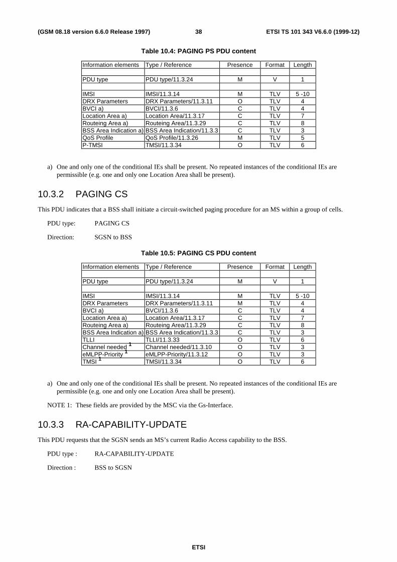
ETSI
ETSI TS 101 343 V6.6.0 (1999-12)38(GSM 08.18 version 6.6.0 Release 1997)
Table 10.4: PAGING PS PDU content
Information elements Type / Reference Presence Format Length
PDU type PDU type/11.3.24 M V 1
IMSI IMSI/11.3.14 M TLV 5 -10DRX Parameters DRX Parameters/11.3.11 O TLV 4BVCI a) BVCI/11.3.6 C TLV 4Location Area a) Location Area/11.3.17 C TLV 7Routeing Area a) Routeing Area/11.3.29 C TLV 8BSS Area Indication a) BSS Area Indication/11.3.3 C TLV 3QoS Profile QoS Profile/11.3.26 M TLV 5P-TMSI TMSI/11.3.34 O TLV 6
a) One and only one of the conditional IEs shall be present. No repeated instances of the conditional IEs arepermissible (e.g. one and only one Location Area shall be present).
10.3.2 PAGING CS
This PDU indicates that a BSS shall initiate a circuit-switched paging procedure for an MS within a group of cells.
PDU type: PAGING CS
Direction: SGSN to BSS
Table 10.5: PAGING CS PDU content
Information elements Type / Reference Presence Format Length
PDU type PDU type/11.3.24 M V 1
IMSI IMSI/11.3.14 M TLV 5 -10DRX Parameters DRX Parameters/11.3.11 M TLV 4BVCI a) BVCI/11.3.6 C TLV 4Location Area a) Location Area/11.3.17 C TLV 7Routeing Area a) Routeing Area/11.3.29 C TLV 8BSS Area Indication a) BSS Area Indication/11.3.3 C TLV 3TLLI TLLI/11.3.33 O TLV 6Channel needed 1 Channel needed/11.3.10 O TLV 3eMLPP-Priority 1 eMLPP-Priority/11.3.12 O TLV 3TMSI 1 TMSI/11.3.34 O TLV 6
a) One and only one of the conditional IEs shall be present. No repeated instances of the conditional IEs arepermissible (e.g. one and only one Location Area shall be present).
NOTE 1: These fields are provided by the MSC via the Gs-Interface.
10.3.3 RA-CAPABILITY-UPDATE
This PDU requests that the SGSN sends an MS’s current Radio Access capability to the BSS.
PDU type : RA-CAPABILITY-UPDATE
Direction : BSS to SGSN
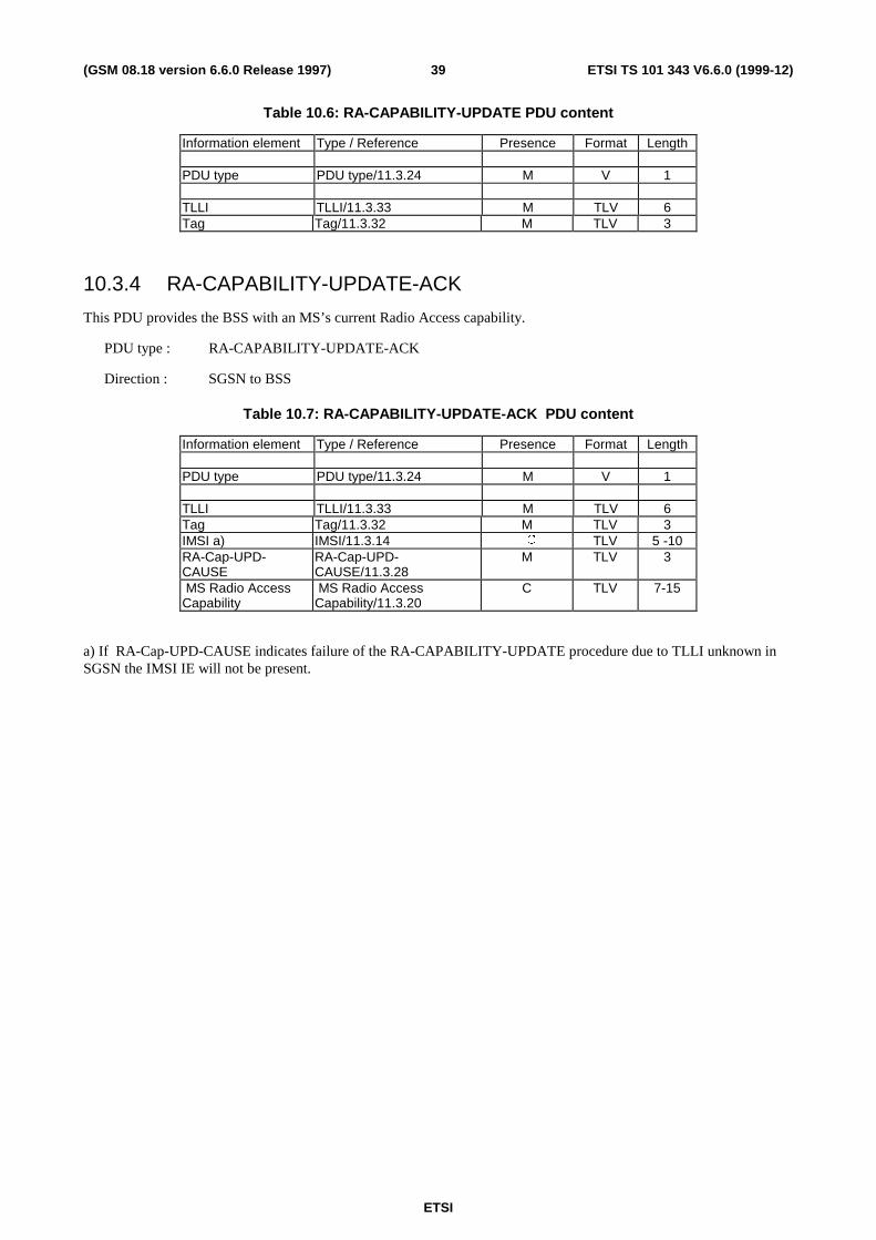
ETSI
ETSI TS 101 343 V6.6.0 (1999-12)39(GSM 08.18 version 6.6.0 Release 1997)
Table 10.6: RA-CAPABILITY-UPDATE PDU content
Information element Type / Reference Presence Format Length
PDU type PDU type/11.3.24 M V 1
TLLI TLLI/11.3.33 M TLV 6Tag Tag/11.3.32 M TLV 3
10.3.4 RA-CAPABILITY-UPDATE-ACK
This PDU provides the BSS with an MS’s current Radio Access capability.
PDU type : RA-CAPABILITY-UPDATE-ACK
Direction : SGSN to BSS
Table 10.7: RA-CAPABILITY-UPDATE-ACK PDU content
Information element Type / Reference Presence Format Length
PDU type PDU type/11.3.24 M V 1
TLLI TLLI/11.3.33 M TLV 6Tag Tag/11.3.32 M TLV 3IMSI a) IMSI/11.3.14 �� TLV 5 -10RA-Cap-UPD-CAUSE
RA-Cap-UPD-CAUSE/11.3.28
M TLV 3
MS Radio AccessCapability
MS Radio AccessCapability/11.3.20
C TLV 7-15
a) If RA-Cap-UPD-CAUSE indicates failure of the RA-CAPABILITY-UPDATE procedure due to TLLI unknown inSGSN the IMSI IE will not be present.
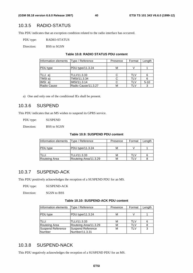
ETSI
ETSI TS 101 343 V6.6.0 (1999-12)40(GSM 08.18 version 6.6.0 Release 1997)
10.3.5 RADIO-STATUS
This PDU indicates that an exception condition related to the radio interface has occurred.
PDU type: RADIO-STATUS
Direction: BSS to SGSN
Table 10.8: RADIO STATUS PDU content
Information elements Type / Reference Presence Format Length
PDU type PDU type/11.3.24 M V 1
TLLI a) TLLI/11.3.33 C TLV 6TMSI a) TMSI/11.3.34 C TLV 6IMSI a) IMSI/11.3.14 C TLV 5-10Radio Cause Radio Cause/11.3.27 M TLV 3
a) One and only one of the conditional IEs shall be present.
10.3.6 SUSPEND
This PDU indicates that an MS wishes to suspend its GPRS service.
PDU type: SUSPEND
Direction: BSS to SGSN
Table 10.9: SUSPEND PDU content
Information elements Type / Reference Presence Format Length
PDU type PDU type/11.3.24 M V 1
TLLI TLLI/11.3.33 M TLV 6Routeing Area Routeing Area/11.3.29 M TLV 8
10.3.7 SUSPEND-ACK
This PDU positively acknowledges the reception of a SUSPEND PDU for an MS.
PDU type: SUSPEND-ACK
Direction: SGSN to BSS
Table 10.10: SUSPEND-ACK PDU content
Information elements Type / Reference Presence Format Length
PDU type PDU type/11.3.24 M V 1
TLLI TLLI/11.3.33 M TLV 6Routeing Area Routeing Area/11.3.29 M TLV 8Suspend ReferenceNumber
Suspend ReferenceNumber/11.3.31
M TLV 3
10.3.8 SUSPEND-NACK
This PDU negatively acknowledges the reception of a SUSPEND PDU for an MS.

ETSI
ETSI TS 101 343 V6.6.0 (1999-12)41(GSM 08.18 version 6.6.0 Release 1997)
PDU type: SUSPEND-NACK
Direction: SGSN to BSS
Table 10.11: SUSPEND-NACK PDU content
Information elements Type / Reference Presence Format Length
PDU type PDU type/11.3.24 M V 1
TLLI TLLI/11.3.33 M TLV 6Routeing Area Routeing Area/11.3.29 M TLV 8Cause Cause/11.3.8 O TLV 3
10.3.9 RESUME
This PDU indicates that an MS wishes to RESUME its GPRS service.
PDU type: RESUME
Direction: BSS to SGSN
Table 10.12: RESUME PDU content
Information elements Type / Reference Presence Format Length
PDU type PDU type/11.3.24 M V 1
TLLI TLLI/11.3.33 M TLV 6Routeing Area Routeing Area/11.3.29 M TLV 8Suspend ReferenceNumber
Suspend ReferenceNumber/11.3.31
M TLV 3
10.3.10 RESUME-ACK
This PDU positively acknowledges the reception of a RESUME PDU for an MS.
PDU type: RESUME-ACK
Direction: SGSN to BSS
Table 10.13: RESUME-ACK PDU content
Information elements Type / Reference Presence Format Length
PDU type PDU type/11.3.24 M V 1
TLLI TLLI/11.3.33 M TLV 6Routeing Area Routeing Area/11.3.29 M TLV 8
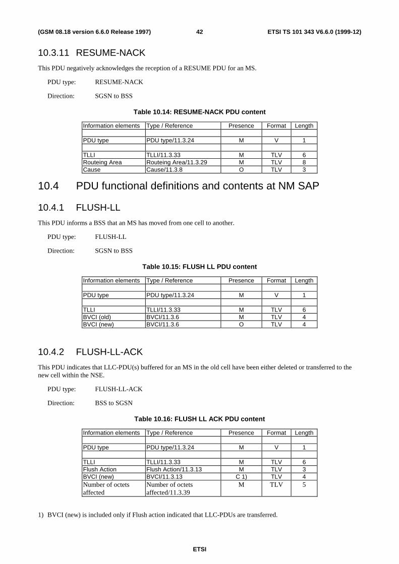
ETSI
ETSI TS 101 343 V6.6.0 (1999-12)42(GSM 08.18 version 6.6.0 Release 1997)
10.3.11 RESUME-NACK
This PDU negatively acknowledges the reception of a RESUME PDU for an MS.
PDU type: RESUME-NACK
Direction: SGSN to BSS
Table 10.14: RESUME-NACK PDU content
Information elements Type / Reference Presence Format Length
PDU type PDU type/11.3.24 M V 1
TLLI TLLI/11.3.33 M TLV 6Routeing Area Routeing Area/11.3.29 M TLV 8Cause Cause/11.3.8 O TLV 3
10.4 PDU functional definitions and contents at NM SAP
10.4.1 FLUSH-LL
This PDU informs a BSS that an MS has moved from one cell to another.
PDU type: FLUSH-LL
Direction: SGSN to BSS
Table 10.15: FLUSH LL PDU content
Information elements Type / Reference Presence Format Length
PDU type PDU type/11.3.24 M V 1
TLLI TLLI/11.3.33 M TLV 6BVCI (old) BVCI/11.3.6 M TLV 4BVCI (new) BVCI/11.3.6 O TLV 4
10.4.2 FLUSH-LL-ACK
This PDU indicates that LLC-PDU(s) buffered for an MS in the old cell have been either deleted or transferred to thenew cell within the NSE.
PDU type: FLUSH-LL-ACK
Direction: BSS to SGSN
Table 10.16: FLUSH LL ACK PDU content
Information elements Type / Reference Presence Format Length
PDU type PDU type/11.3.24 M V 1
TLLI TLLI/11.3.33 M TLV 6Flush Action Flush Action/11.3.13 M TLV 3BVCI (new) BVCI/11.3.13 C 1) TLV 4Number of octetsaffected
Number of octetsaffected/11.3.39
M TLV 5
1) BVCI (new) is included only if Flush action indicated that LLC-PDUs are transferred.

ETSI
ETSI TS 101 343 V6.6.0 (1999-12)43(GSM 08.18 version 6.6.0 Release 1997)
10.4.3 LLC-DISCARDED
This PDU indicates that a number of buffered LLC-PDUs in a cell for an MS have been deleted inside the BSS (becauseof PDU Lifetime expiration or Cell-reselection for example).
PDU type: LLC-DISCARDED
Direction: BSS to SGSN
Table 10.17: LLC DISCARDED PDU content
Information elements Type / Reference Presence Format Length
PDU type PDU type/11.3.24 M V 1
TLLI TLLI/11.3.33 M TLV 6LLC FramesDiscarded
LLC FramesDiscarded/11.3.16
M TLV 3
BVCI BVCI/11.3.6 M TLV 4Number of octetsdeleted
Number of octetsaffected/11.3.39
M TLV 5
10.4.4 FLOW-CONTROL-BVC
This PDU informs the flow control mechanism at an SGSN of the status of a BVC’s maximum acceptable SGSN to BSSthroughput on the Gb interface.
PDU type: FLOW-CONTROL-BVC
Direction: BSS to SGSN
Table 10.18: FLOW-CONTROL-BVC PDU content
Information elements Type / Reference Presence Format Length
PDU type PDU type/11.3.24 M V 1
Tag Tag/11.3.32 M TLV 3BVC Bucket Size BVC Bucket Size/11.3.5 M TLV 4Bucket Leak Rate Bucket Leak Rate/11.3.4 M TLV 4Bmax default MS Bmax default MS/11.3.2 M TLV 4R_default_MS R_default_MS/11.3.30 M TLV 4BVC Measurement BVC Measurement/11.3.7 O TLV 4
10.4.5 FLOW-CONTROL-BVC-ACK
This PDU informs the flow control mechanism at the BSS that the SGSN has received the FLOW-CONTROL-BVCPDU indicated by the Tag.
PDU type: FLOW-CONTROL-BVC-ACK
Direction: SGSN to BSS
Table 10.19: FLOW-CONTROL-BVC-ACK PDU content
Information elements Type / Reference Presence Format Length
PDU type PDU type/11.3.24 M V 1
Tag Tag/11.3.32 M TLV 3
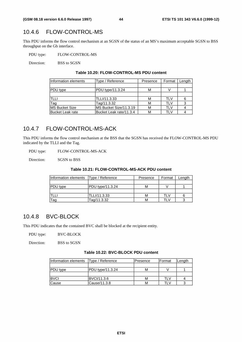
ETSI
ETSI TS 101 343 V6.6.0 (1999-12)44(GSM 08.18 version 6.6.0 Release 1997)
10.4.6 FLOW-CONTROL-MS
This PDU informs the flow control mechanism at an SGSN of the status of an MS’s maximum acceptable SGSN to BSSthroughput on the Gb interface.
PDU type: FLOW-CONTROL-MS
Direction: BSS to SGSN
Table 10.20: FLOW-CONTROL-MS PDU content
Information elements Type / Reference Presence Format Length
PDU type PDU type/11.3.24 M V 1
TLLI TLLI/11.3.33 M TLV 6Tag Tag/11.3.32 M TLV 3MS Bucket Size MS Bucket Size/11.3.19 M TLV 4Bucket Leak rate Bucket Leak rate/11.3.4 M TLV 4
10.4.7 FLOW-CONTROL-MS-ACK
This PDU informs the flow control mechanism at the BSS that the SGSN has received the FLOW-CONTROL-MS PDUindicated by the TLLI and the Tag.
PDU type: FLOW-CONTROL-MS-ACK
Direction: SGSN to BSS
Table 10.21: FLOW-CONTROL-MS-ACK PDU content
Information elements Type / Reference Presence Format Length
PDU type PDU type/11.3.24 M V 1
TLLI TLLI/11.3.33 M TLV 6Tag Tag/11.3.32 M TLV 3
10.4.8 BVC-BLOCK
This PDU indicates that the contained BVC shall be blocked at the recipient entity.
PDU type: BVC-BLOCK
Direction: BSS to SGSN
Table 10.22: BVC-BLOCK PDU content
Information elements Type / Reference Presence Format Length
PDU type PDU type/11.3.24 M V 1
BVCI BVCI/11.3.6 M TLV 4Cause Cause/11.3.8 M TLV 3
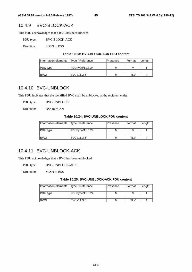
ETSI
ETSI TS 101 343 V6.6.0 (1999-12)45(GSM 08.18 version 6.6.0 Release 1997)
10.4.9 BVC-BLOCK-ACK
This PDU acknowledges that a BVC has been blocked.
PDU type: BVC-BLOCK-ACK
Direction: SGSN to BSS
Table 10.23: BVC-BLOCK-ACK PDU content
Information elements Type / Reference Presence Format Length
PDU type PDU type/11.3.24 M V 1
BVCI BVCI/11.3.6 M TLV 4
10.4.10 BVC-UNBLOCK
This PDU indicates that the identified BVC shall be unblocked at the recipient entity.
PDU type: BVC-UNBLOCK
Direction: BSS to SGSN
Table 10.24: BVC-UNBLOCK PDU content
Information elements Type / Reference Presence Format Length
PDU type PDU type/11.3.24 M V 1
BVCI BVCI/11.3.6 M TLV 4
10.4.11 BVC-UNBLOCK-ACK
This PDU acknowledges that a BVC has been unblocked.
PDU type: BVC-UNBLOCK-ACK
Direction: SGSN to BSS
Table 10.25: BVC-UNBLOCK-ACK PDU content
Information elements Type / Reference Presence Format Length
PDU type PDU type/11.3.24 M V 1
BVCI BVCI/11.3.6 M TLV 4
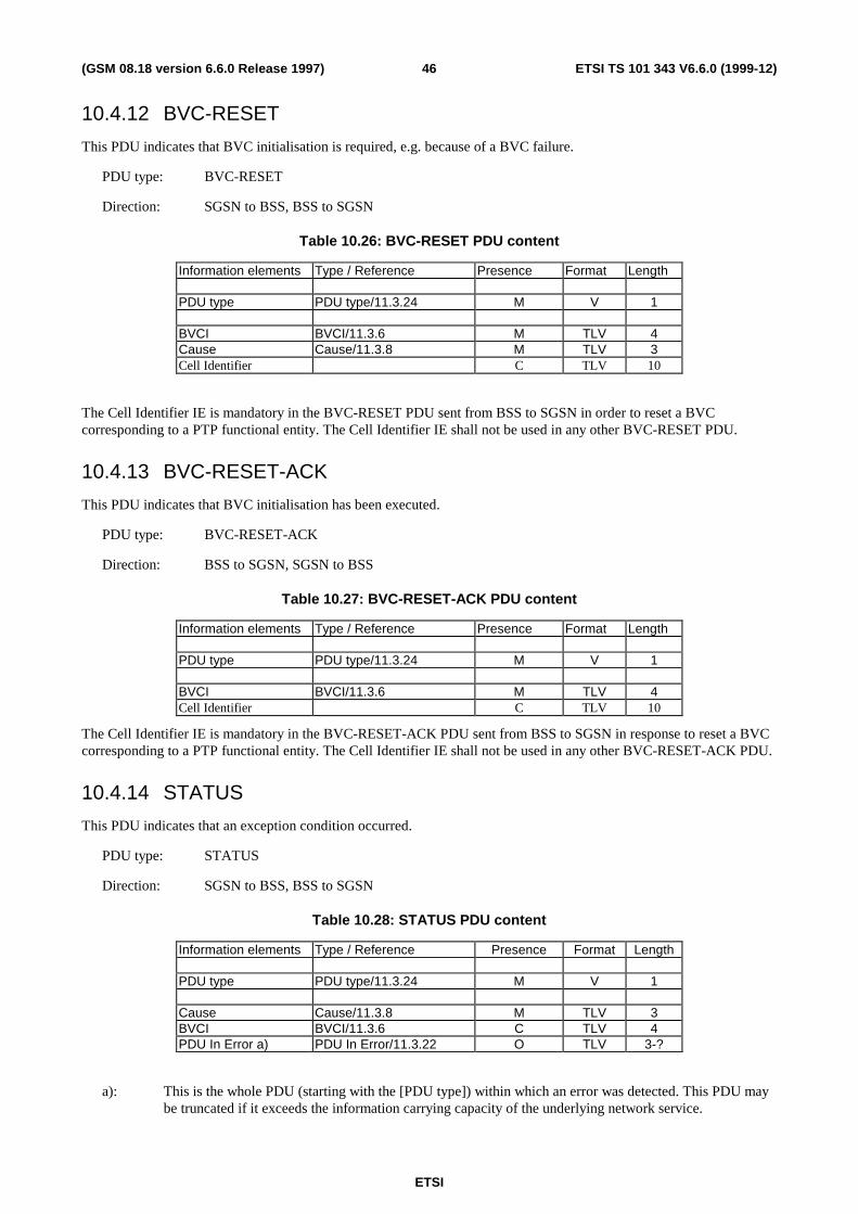
ETSI
ETSI TS 101 343 V6.6.0 (1999-12)46(GSM 08.18 version 6.6.0 Release 1997)
10.4.12 BVC-RESET
This PDU indicates that BVC initialisation is required, e.g. because of a BVC failure.
PDU type: BVC-RESET
Direction: SGSN to BSS, BSS to SGSN
Table 10.26: BVC-RESET PDU content
Information elements Type / Reference Presence Format Length
PDU type PDU type/11.3.24 M V 1
BVCI BVCI/11.3.6 M TLV 4Cause Cause/11.3.8 M TLV 3Cell Identifier C TLV 10
The Cell Identifier IE is mandatory in the BVC-RESET PDU sent from BSS to SGSN in order to reset a BVCcorresponding to a PTP functional entity. The Cell Identifier IE shall not be used in any other BVC-RESET PDU.
10.4.13 BVC-RESET-ACK
This PDU indicates that BVC initialisation has been executed.
PDU type: BVC-RESET-ACK
Direction: BSS to SGSN, SGSN to BSS
Table 10.27: BVC-RESET-ACK PDU content
Information elements Type / Reference Presence Format Length
PDU type PDU type/11.3.24 M V 1
BVCI BVCI/11.3.6 M TLV 4Cell Identifier C TLV 10
The Cell Identifier IE is mandatory in the BVC-RESET-ACK PDU sent from BSS to SGSN in response to reset a BVCcorresponding to a PTP functional entity. The Cell Identifier IE shall not be used in any other BVC-RESET-ACK PDU.
10.4.14 STATUS
This PDU indicates that an exception condition occurred.
PDU type: STATUS
Direction: SGSN to BSS, BSS to SGSN
Table 10.28: STATUS PDU content
Information elements Type / Reference Presence Format Length
PDU type PDU type/11.3.24 M V 1
Cause Cause/11.3.8 M TLV 3BVCI BVCI/11.3.6 C TLV 4PDU In Error a) PDU In Error/11.3.22 O TLV 3-?
a): This is the whole PDU (starting with the [PDU type]) within which an error was detected. This PDU maybe truncated if it exceeds the information carrying capacity of the underlying network service.

ETSI
ETSI TS 101 343 V6.6.0 (1999-12)47(GSM 08.18 version 6.6.0 Release 1997)
10.4.14.1 Static conditions for BVCI
The "BVCI" IE shall be included when the "Cause" IE is set to one of the following values:
a) "BVCI blocked",
and shall not be included otherwise.
10.4.15 SGSN-INVOKE-TRACE
This PDU indicates that the BSS shall begin the production of a trace record for an MS.
PDU type: SGSN-INVOKE-TRACE
Direction: SGSN to BSS
Table 10.29: SGSN-INVOKE-TRACE PDU content
IEI Information elements Type / Reference Presence Format Length
PDU type PDU type/11.3.24 M V 1
Trace Type Trace Type/11.3.36 M TLV 3Trace Reference Trace Reference/11.3.35 M TLV 4Trigger Id Trigger Id/11.3.38 O TLV 4-24Mobile Id Mobile Id/11.3.18 O TLV 3-10OMC Id OMC Id/11.3.21 O TLV 4-24TransactionId TransactionId/11.3.37 O TLV 4
11 General information elements codingThe figures and text in this section describe the Information Elements contents.
11.1 General structure of the information elementsRefer to General Structure Of The Information Elements/GSM 08.16 [16].
11.2 Information element descriptionRefer to Information Element Description/GSM 08.16 [16].
11.3 Information Element Identifier (IEI)An Information Element Identifier (IEI) is identified by the same coding in all BSSGP PDUs.

ETSI
ETSI TS 101 343 V6.6.0 (1999-12)48(GSM 08.18 version 6.6.0 Release 1997)
Table 11.1: IEI types
IEI coding IEI Types
(hexadecimal)
x00 Alignment Octetsx01 Bmax default MSx02 BSS Area Indicationx03 Bucket Leak Ratex04 BVCIx05 BVC Bucket Sizex06 BVC Measurementx07 Causex08 Cell Identifierx09 Channel neededx0a DRX Parametersx0b eMLPP-Priorityx0c Flush Actionx0d IMSIx0e LLC-PDUx0f LLC Frames Discardedx10 Location Areax11 Mobile Idx12 MS Bucket Sizex13 MS Radio Access Capabilityx14 OMC Idx15 PDU In Errorx16 PDU Lifetimex17 Priorityx18 QoS Profilex19 Radio Causex1a RA-Cap-UPD-Causex1b Routeing Areax1c R_default_MSx1d Suspend Reference Numberx1e Tagx1f TLLIx20 TMSIx21 Trace Referencex22 Trace Typex23 TransactionIdx24 Trigger Idx25 Number of octets affected
RESERVED All values not explicitly shown are reserved for future use andshall be treated by the recipient as an unknown IEI
11.3.1 Alignment octets
The Alignment Octets are used to align a subsequent IEI onto a 32 bit boundary. The element coding is:
Table 11.2: Alignment octets IE
8 7 6 5 4 3 2 1octet 1 IEIoctet 2,2a Length Indicator a)octet 3-5 spare octet
a) The Length Indicator may indicate that from 0 to 3 spare octets are present.

ETSI
ETSI TS 101 343 V6.6.0 (1999-12)49(GSM 08.18 version 6.6.0 Release 1997)
11.3.2 Bmax default MS
This information element indicates the default bucket size (Bmax) in octets for an MS. The element coding is:
Table 11.3: Bmax default MS IE
8 7 6 5 4 3 2 1octet 1 IEIoctet 2,2a Length Indicatoroctet 3-4 Bmax
The Bmax field is coded as in section GSM 08.18 BVC Bucket Size/Bmax.
11.3.3 BSS Area Indication
This element is used to indicate that the paging shall be done in all the cells within the BSS. The element coding is:
Table 11.4: BSS Area Indication IE
8 7 6 5 4 3 2 1octet 1 IEIoctet 2,2a Length Indicatoroctet 3 BSS indicator
The coding of octet 2 is a binary number indicating the Length of the remaining element.
The coding of octet 3 shall not be specified. The recipient shall ignore the value of this octet.
11.3.4 Bucket Leak Rate (R)
This information element indicates the leak rate (R) to be applied to a flow control bucket. The element coding is:
Table 11.5: Bucket Leak Rate IE
8 7 6 5 4 3 2 1octet 1 IEIoctet 2,2a Length Indicatoroctet 3 R Value (MSB)octet 4 R Value (LSB)
The R field is the binary encoding of the rate information expressed in 100 bits/sec increments, starting from 0 x 100bits/sec until 65535 x 100 bits/sec (6 Mbps).
11.3.5 BVC Bucket Size
This information element indicates the maximum bucket size (Bmax) in octets for a BVC. The element coding is:
Table 11.6: BVC Bucket Size IE
8 7 6 5 4 3 2 1octet 1 IEIoctet 2,2a Length Indicatoroctet 3 Bmax (MSB)octet 4 Bmax (LSB)
The Bmax field is the binary encoding of the bucket-size information expressed in 100 octet increments, starting from 0x 100 octets until 65535 x 100 octets (6 Mbytes).

ETSI
ETSI TS 101 343 V6.6.0 (1999-12)50(GSM 08.18 version 6.6.0 Release 1997)
11.3.6 BVCI (BSSGP Virtual Connection Identifier)
The BVCI identifies a BVC. The element coding is:
Table 11.7: BVCI IE
8 7 6 5 4 3 2 1octet 1 IEIoctet 2,2a Length Indicatoroctet 3-4 Unstructured value
11.3.7 BVC Measurement
This information element describes average queuing delay for a BVC. The element coding is:
Table 11.8: BVC Measurement IE
8 7 6 5 4 3 2 1octet 1 IEIoctet 2,2a Length Indicatoroctet 3,4 Delay Value (in centi-seconds)
The Delay Value field is coded as a 16-bit integer value in units of centi-seconds (one hundredth of a second). Thiscoding provides a range of over 10 minutes in increments of 10 msec. As a special case, the hexadecimal value 0xFFFF(decimal 65535) shall be interpreted as “infinite delay”.
11.3.8 Cause
The Cause information element indicates the reason for an exception condition. The element coding is:
Table 11.9: Cause IE
8 7 6 5 4 3 2 1octet 1 IEIoctet 2,2a Length Indicatoroctet 3 Cause value
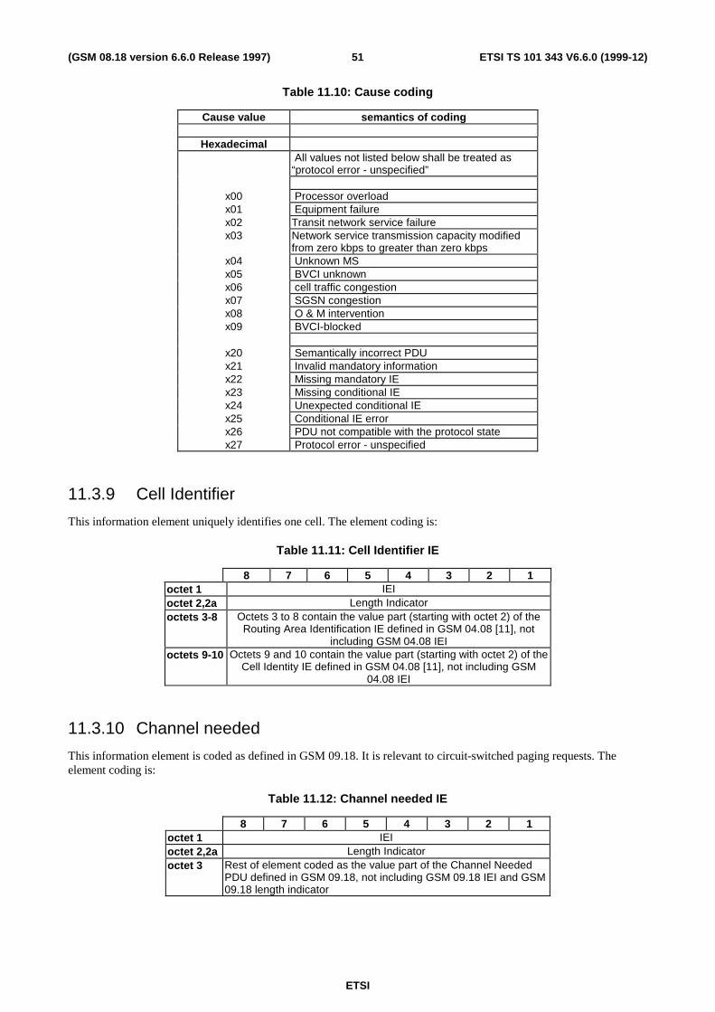
ETSI
ETSI TS 101 343 V6.6.0 (1999-12)51(GSM 08.18 version 6.6.0 Release 1997)
Table 11.10: Cause coding
Cause value semantics of coding
HexadecimalAll values not listed below shall be treated as
“protocol error - unspecified”
x00 Processor overloadx01 Equipment failurex02 Transit network service failurex03 Network service transmission capacity modified
from zero kbps to greater than zero kbpsx04 Unknown MSx05 BVCI unknownx06 cell traffic congestionx07 SGSN congestionx08 O & M interventionx09 BVCI-blocked
x20 Semantically incorrect PDUx21 Invalid mandatory informationx22 Missing mandatory IEx23 Missing conditional IEx24 Unexpected conditional IEx25 Conditional IE errorx26 PDU not compatible with the protocol statex27 Protocol error - unspecified
11.3.9 Cell Identifier
This information element uniquely identifies one cell. The element coding is:
Table 11.11: Cell Identifier IE
8 7 6 5 4 3 2 1octet 1 IEIoctet 2,2a Length Indicatoroctets 3-8 Octets 3 to 8 contain the value part (starting with octet 2) of the
Routing Area Identification IE defined in GSM 04.08 [11], notincluding GSM 04.08 IEI
octets 9-10 Octets 9 and 10 contain the value part (starting with octet 2) of theCell Identity IE defined in GSM 04.08 [11], not including GSM
04.08 IEI
11.3.10 Channel needed
This information element is coded as defined in GSM 09.18. It is relevant to circuit-switched paging requests. Theelement coding is:
Table 11.12: Channel needed IE
8 7 6 5 4 3 2 1octet 1 IEIoctet 2,2a Length Indicatoroctet 3 Rest of element coded as the value part of the Channel Needed
PDU defined in GSM 09.18, not including GSM 09.18 IEI and GSM09.18 length indicator
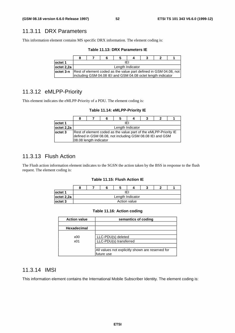
ETSI
ETSI TS 101 343 V6.6.0 (1999-12)52(GSM 08.18 version 6.6.0 Release 1997)
11.3.11 DRX Parameters
This information element contains MS specific DRX information. The element coding is:
Table 11.13: DRX Parameters IE
8 7 6 5 4 3 2 1octet 1 IEIoctet 2,2a Length Indicatoroctet 3-n Rest of element coded as the value part defined in GSM 04.08, not
including GSM 04.08 IEI and GSM 04.08 octet length indicator
11.3.12 eMLPP-Priority
This element indicates the eMLPP-Priority of a PDU. The element coding is:
Table 11.14: eMLPP-Priority IE
8 7 6 5 4 3 2 1octet 1 IEIoctet 2,2a Length Indicatoroctet 3 Rest of element coded as the value part of the eMLPP-Priority IE
defined in GSM 08.08, not including GSM 08.08 IEI and GSM08.08 length indicator
11.3.13 Flush Action
The Flush action information element indicates to the SGSN the action taken by the BSS in response to the flushrequest. The element coding is:
Table 11.15: Flush Action IE
8 7 6 5 4 3 2 1octet 1 IEIoctet 2,2a Length Indicatoroctet 3 Action value
Table 11.16: Action coding
Action value semantics of coding
Hexadecimal
x00 LLC-PDU(s) deletedx01 LLC-PDU(s) transferred
All values not explicitly shown are reserved forfuture use
11.3.14 IMSI
This information element contains the International Mobile Subscriber Identity. The element coding is:

ETSI
ETSI TS 101 343 V6.6.0 (1999-12)53(GSM 08.18 version 6.6.0 Release 1997)
Table 11.17: IMSI IE
8 7 6 5 4 3 2 1octet 1 IEIoctet 2,2a Length Indicatoroctet 3-n Octets 3-n contain an IMSI coded as the value part (starting with
octet 3) of the Mobile Identity IE defined in GSM 04.08, notincluding GSM 04.08 IEI and GSM 04.08 length indicator
11.3.15 LLC-PDU
This information element contains an LLC-PDU. The element coding is:
Table 11.18: LLC-PDU IE
8 7 6 5 4 3 2 1octet 1 IEIoctet 2,2a Length Indicatoroctet 3 LLC-PDU (first part)octet n LLC-PDU (last part)
11.3.16 LLC Frames Discarded
This element describes the number of LLC frames that have been discarded inside a BSS. The element coding is:
Table 11.19: LLC Frames Discarded IE
8 7 6 5 4 3 2 1octet 1 IEIoctet 2,2a Length Indicatoroctet 3 Number of frames discarded (in hexadecimal)
11.3.17 Location Area
This element uniquely identifies one Location Area. The element coding is:
Table 11.20: Location Area IE
8 7 6 5 4 3 2 1octet 1 IEIoctet 2,2a Length IndicatorOctets 3-7 Octets 3 to 7 contain the value part (starting with octet 2) of the
Location Area Identification IE defined in GSM 04.08 [11], notincluding GSM 04.08 IEI
The coding of octet 2 is a binary number indicating the Length of the remaining element.
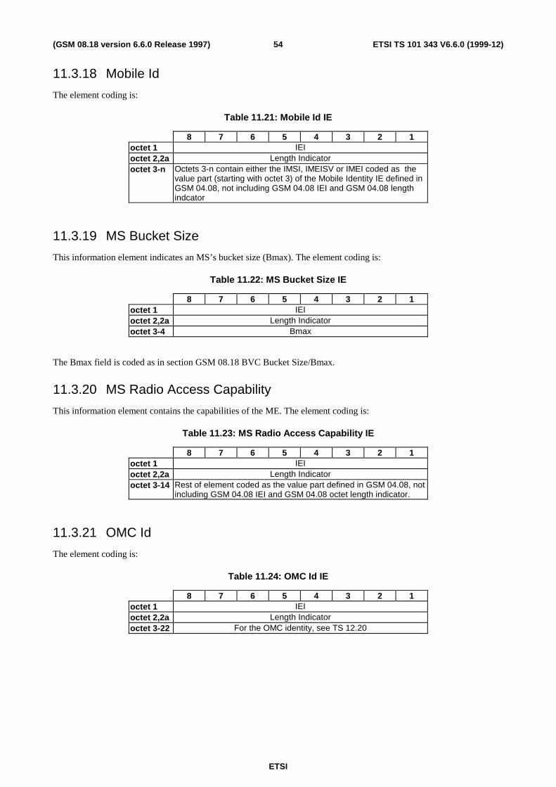
ETSI
ETSI TS 101 343 V6.6.0 (1999-12)54(GSM 08.18 version 6.6.0 Release 1997)
11.3.18 Mobile Id
The element coding is:
Table 11.21: Mobile Id IE
8 7 6 5 4 3 2 1octet 1 IEIoctet 2,2a Length Indicatoroctet 3-n Octets 3-n contain either the IMSI, IMEISV or IMEI coded as the
value part (starting with octet 3) of the Mobile Identity IE defined inGSM 04.08, not including GSM 04.08 IEI and GSM 04.08 lengthindcator
11.3.19 MS Bucket Size
This information element indicates an MS’s bucket size (Bmax). The element coding is:
Table 11.22: MS Bucket Size IE
8 7 6 5 4 3 2 1octet 1 IEIoctet 2,2a Length Indicatoroctet 3-4 Bmax
The Bmax field is coded as in section GSM 08.18 BVC Bucket Size/Bmax.
11.3.20 MS Radio Access Capability
This information element contains the capabilities of the ME. The element coding is:
Table 11.23: MS Radio Access Capability IE
8 7 6 5 4 3 2 1octet 1 IEIoctet 2,2a Length Indicatoroctet 3-14 Rest of element coded as the value part defined in GSM 04.08, not
including GSM 04.08 IEI and GSM 04.08 octet length indicator.
11.3.21 OMC Id
The element coding is:
Table 11.24: OMC Id IE
8 7 6 5 4 3 2 1octet 1 IEIoctet 2,2a Length Indicatoroctet 3-22 For the OMC identity, see TS 12.20
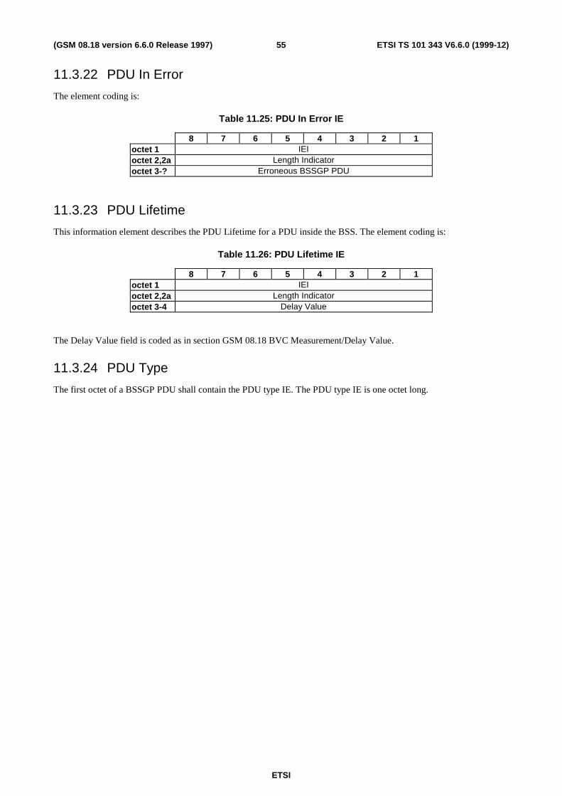
ETSI
ETSI TS 101 343 V6.6.0 (1999-12)55(GSM 08.18 version 6.6.0 Release 1997)
11.3.22 PDU In Error
The element coding is:
Table 11.25: PDU In Error IE
8 7 6 5 4 3 2 1octet 1 IEIoctet 2,2a Length Indicatoroctet 3-? Erroneous BSSGP PDU
11.3.23 PDU Lifetime
This information element describes the PDU Lifetime for a PDU inside the BSS. The element coding is:
Table 11.26: PDU Lifetime IE
8 7 6 5 4 3 2 1octet 1 IEIoctet 2,2a Length Indicatoroctet 3-4 Delay Value
The Delay Value field is coded as in section GSM 08.18 BVC Measurement/Delay Value.
11.3.24 PDU Type
The first octet of a BSSGP PDU shall contain the PDU type IE. The PDU type IE is one octet long.

ETSI
ETSI TS 101 343 V6.6.0 (1999-12)56(GSM 08.18 version 6.6.0 Release 1997)
Table 11.27: PDU Types
PDU type coding PDU Types
(Hexadecimal)PDUs between RL and BSSGP SAPs
x00 - DL-UNITDATAx01 - UL-UNITDATAx02 - RA-CAPABILITYx03 - PTM-UNITDATA
PDUs between GMM SAPsx06 - PAGING PSx07 - PAGING CSx08 - RA-CAPABILITY-UPDATEx09 - RA-CAPABILITY-UPDATE-ACKx0a - RADIO-STATUSx0b - SUSPENDx0c - SUSPEND-ACKx0d - SUSPEND-NACKx0e - RESUMEx0f - RESUME-ACKx10 - RESUME-NACK
PDUs between NM SAPsx20 - BVC-BLOCKx21 - BVC-BLOCK-ACKx22 - BVC-RESETx23 - BVC-RESET-ACKx24 - BVC-UNBLOCKx25 - BVC-UNBLOCK-ACKx26 - FLOW-CONTROL-BVCx27 - FLOW-CONTROL-BVC-ACKx28 - FLOW-CONTROL-MSx29 - FLOW-CONTROL-MS-ACKx2a - FLUSH-LLx2b - FLUSH-LL-ACKx2c - LLC-DISCARDED
x40 - SGSN-INVOKE-TRACEx41 - STATUS
RESERVED all values not explicitly shown are reserved for future use
11.3.25 Priority
This element indicates the priority of a PDU. The element coding is:
Table 11.28: Priority IE
8 7 6 5 4 3 2 1octet 1 IEIoctet 2,2a Length Indicatoroctet 3 Rest of element coded as the value part of the Priority IE defined in
GSM 08.08, not including GSM 08.08 IEI and GSM 08.08 lengthindicator

ETSI
ETSI TS 101 343 V6.6.0 (1999-12)57(GSM 08.18 version 6.6.0 Release 1997)
11.3.26 QoS Profile
This information element describes the QoS Profile associated with a PDU. The element coding is:
Table 11.29: QoS Profile IE
8 7 6 5 4 3 2 1octet 1 IEIoctet 2,2a Length Indicatoroctet 3-4 Peak bit rate provided by the network, coded as the value part in
Bucket Leak Rate/R IE/ GSM 08.18 a)octet 5 SPARE C/R T A Precedence
a) The bit rate 0 (zero) shall mean “best effort” in this IE.
“Precedence” is coded as shown below (complying with GSM 03.60).
Table 11.30: Precedence coding
coding semanticDL-UNITDATA UL-UNITDATA
000 High priority Radio priority 1001 Normal priority Radio priority 2010 Low priority Radio priority 3011 Reserved Radio priority 4100 Reserved Radio Priority Unknown
All values not allocated are reserved. All reserved values shall be interpreted as value 010.
“A-bit” is coded as shown below.
Table 11.31: “A bit” coding
coding semantic0 Radio interface uses RLC/MAC ARQ functionality1 Radio interface uses RLC/MAC-UNITDATA functionality
“T-bit” is coded as shown below.
Table 11.32: “T bit” coding
coding semantic0 The SDU contains signalling (e.g. related to GMM)1 The SDU contains data
“C/R-bit” is coded as shown below.
Table 11.47: “C/R bit” coding
coding semantic0 The SDU contains a LLC ACK or SACK command/response
frame type1 The SDU does not contain a LLC ACK or SACK
command/response frame type

ETSI
ETSI TS 101 343 V6.6.0 (1999-12)58(GSM 08.18 version 6.6.0 Release 1997)
11.3.27 Radio Cause
This information element indicates the reason for an exception condition on the radio interface. The element coding is:
Table 11.33: Radio Cause IE
8 7 6 5 4 3 2 1octet 1 IEIoctet 2,2a Length Indicatoroctet 3 Radio Cause value
Table 11.34: Radio Cause value
radio cause value semantics of coding
(Hexadecimal)x00 Radio contact lost with the MSx01 Radio link quality insufficient to continue
communicationx02 cell-reselection ordered
All values not explicitly listed are reserved. Ifreceived, they shall be handled as “radio contactlost with the MS”.
11.3.28 RA-Cap-UPD-Cause
The RA-Cap-UPD-Cause indicates the success of the RA-CAPABILITY-UPDATE procedure or the reason of the failure.The element coding is:
Table 11.35: RA-Cap-UPD-Cause IE
8 7 6 5 4 3 2 1octet 1 IEIoctet 2,2a Length Indicatoroctet 3 RA-Cap-UPD Cause value
Table 11.36: RA-Cap-UPD Cause value
RA-Cap-UPD causevalue
semantics of coding
(Hexadecimal)x00 OK, RA capability IE presentx01 TLLI unknown in SGSNx02 no RA Capabilities available for this MS
All values not explicitly listed are reserved. Ifreceived, they shall be handled as “TLLI unknownin SGSN”.

ETSI
ETSI TS 101 343 V6.6.0 (1999-12)59(GSM 08.18 version 6.6.0 Release 1997)
11.3.29 Routeing Area
This element uniquely identifies one routeing area. The element coding is:
Table 11.37: Routeing Area IE
8 7 6 5 4 3 2 1octet 1 IEIoctet 2,2a Length IndicatorOctets 3-8 Octets 3 to 8 contain the value part (starting with octet 2) of the
Routing Area Identification IE defined in GSM 04.08 [11], notincluding GSM 04.08 IEI
The coding of octet 2 is a binary number indicating the Length of the remaining element.
11.3.30 R_default_MS
This information element indicates the default bucket leak rate (R) to be applied to a flow control bucket for an MS. Theelement coding is:
Table 11.38: R_default_MS IE
8 7 6 5 4 3 2 1octet 1 IEIoctet 2,2a Length Indicatoroctet 3-4 R_default_MS value
The R_default_MS field is coded as in section GSM 08.18 Bucket Leak Rate /R Value.
11.3.31 Suspend Reference Number
The Suspend Reference Number information element contains an un-formatted reference number for eachsuspend/resume transaction. The element coding is:
Table 11.39: Suspend Reference Number IE
8 7 6 5 4 3 2 1octet 1 IEIoctet 2,2a Length Indicatoroctet 3 Suspend Reference Number
The Suspend Reference Number is an un-formatted 8 bit field.
11.3.32 Tag
This information element is used to correlate request and response PDUs. The element coding is:
Table 11.40: Tag IE
8 7 6 5 4 3 2 1octet 1 IEIoctet 2,2a Length Indicatoroctet 3 Unstructured value
11.3.33 Temporary logical link Identity (TLLI)
The element coding is:

ETSI
ETSI TS 101 343 V6.6.0 (1999-12)60(GSM 08.18 version 6.6.0 Release 1997)
Table 11.41: TLLI IE
8 7 6 5 4 3 2 1octet 1 IEIoctet 2,2a Length Indicator
octet 3-6 Rest of element coded as the value part of the TLLI informationelement in GSM 04.08, not including GSM 04.08 IEI.
11.3.34 Temporary Mobile Subscriber Identity (TMSI)
The element coding is:
Table 11.42: TMSI IE
8 7 6 5 4 3 2 1octet 1 IEIoctet 2,2a Length Indicatoroctet 3-6 Rest of element coded as the value part of the TMSI/P-TMSI
information element in GSM 04.08, not including GSM 04.08 IEI.
11.3.35 Trace Reference
This element provides a trace reference number allocated by the triggering entity. The element coding is:
Table 11.43: Trace Reference IE
8 7 6 5 4 3 2 1octet 1 IEIoctet 2,2a Length Indicatoroctet 3-4 Trace Reference
11.3.36 Trace Type
This element provides the type of trace information to be recorded. The element coding is:
Table 11.44: Trace Type IE
8 7 6 5 4 3 2 1octet 1 IEIoctet 2,2a Length Indicatoroctet 3 This is coded as specified in Technical Specification GSM 12.08.
11.3.37 TransactionId
This element indicates a particular transaction within a trace. The element coding is:
Table 11.45: Transaction Id IE
8 7 6 5 4 3 2 1octet 1 IEIoctet 2,2a Length Indicatoroctet 3-4 Transaction Id
11.3.38 Trigger Id
This element provides the identity of the entity which initiated the trace. The element coding is:

ETSI
ETSI TS 101 343 V6.6.0 (1999-12)61(GSM 08.18 version 6.6.0 Release 1997)
Table 11.46: Trigger Id IE
8 7 6 5 4 3 2 1octet 1 IEIoctet 2,2a Length Indicatoroctet 3-22 Entity Identity ( typically an OMC identity)
11.3.39 Number of octets affected
This information element indicates, for an MS, the number of octets transferred or deleted by BSS. The element codingis:
Table 11.24: Number of octets affected IE
8 7 6 5 4 3 2 1octet 1 IEIoctet 2,2a Length Indicatoroctet 3-5 number of octets transferred or deleted
The number of octets transferred or deleted by the BSS may be higher than the maximum Bmax value (6553500). SGSNshall handle any value higher than 6553500 as the value 6553500.
12 List of system variables
12.1 General Variables
Table 12.1: Procedure timers
timermnemonic
value range notes relation to other timers
T1 1s<T1<30s Guards the (un)blockingprocedures
none
T2 1s<T2<120s Guards the reset procedure noneT3 0.1s<T3<10s Guards the suspend procedure noneT4 0.1s<T4<10s Guards the resume procedure noneT5 1s<T5<30s Guards the RA-CAPABILITY-
UPDATE procedurenone
Table 12.2: Procedure retry counters
retry mnemonic retryvalue
notes
BVC-BLOCK-RETRIES 3 noneBVC-UNBLOCK-RETRIES 3 none
BVC-RESET-RETRIES 3 noneSUSPEND-RETRIES 3 noneRESUME-RETRIES 3 none
RA-CAPABILITY-UPDATE-RETRIES 3 none
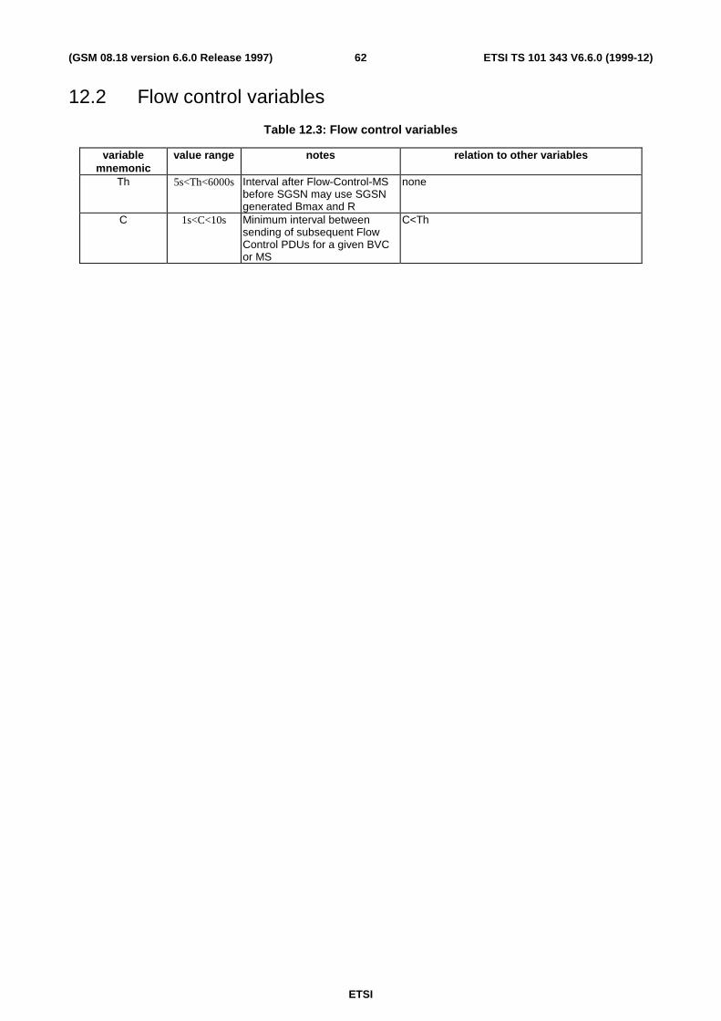
ETSI
ETSI TS 101 343 V6.6.0 (1999-12)62(GSM 08.18 version 6.6.0 Release 1997)
12.2 Flow control variables
Table 12.3: Flow control variables
variablemnemonic
value range notes relation to other variables
Th 5s<Th<6000s Interval after Flow-Control-MSbefore SGSN may use SGSNgenerated Bmax and R
none
C 1s<C<10s Minimum interval betweensending of subsequent FlowControl PDUs for a given BVCor MS
C<Th

ETSI
ETSI TS 101 343 V6.6.0 (1999-12)63(GSM 08.18 version 6.6.0 Release 1997)
Annex A (informative):Change Request History
Document history
5.0.0 December 1997 Approved at SMG#24.
6.0.0 March 1998 Included SMG#25 approved change requests A002, A003, A004, A005, A006 andA008.
6.1.0 June 1998 Includes SMG#26 approved change requests: A001r3, A07r5, A009r2, A010,A011r2, A012r3, A018, A019 and A020r2. Sent to PT12 for formatting.
6.2.0 October 1998 Includes SMG#27 approved change requests: A022r1, A23, A024, A025r2, A026,A030r1, and A031.
6.3.0 March 1999 Includes SMG#28 approved change requests: CR A036 A037r1 A038r1 A039A044 A045 A047r1 A049 A050r1 A051r1 A052 A056r1
6.4.0 July 1999 Includes SMG#29 approved change requests:
CR A042r2 Clarification on mapping of BVCIs to functional entities
CR A058 Encoding of the information elements IMSI, TLLI, TMSI and Mobile Id
CR A059 Correction of RA-CAPABILITY-UPDATE-ACK PDU at failed RA-CAPABILITY-UPDATE procedure.
CR A060r2 Clarification to Paging Procedure
CR A062 Correction of PAGING PS message
CR A064 Length of MS Radio Access Capability IE
6.5.0 November 1999 CR A069r1 Corrections to BSSGP
CR A071 Downlink data transfer
6.6.0 December 1999 CR A067r2 BSSGP error handling
CR A081 FLUSH-LL: Transfer of LLC-PDU(s) to new routing area
ETSI
ETSI TS 101 343 V6.6.0 (1999-12)64(GSM 08.18 version 6.6.0 Release 1997)
History
Document history
V6.1.0 July 1998 Publication
V6.2.0 October 1998 Publication
V6.3.0 March 1999 Publication
V6.4.0 July 1999 Publication
V6.5.0 November 1999 Publication
V6.6.0 December 1999 Publication