ts 100 392-5 - v1.1.1 - terrestrial tunked radio (tetra ......etsi ts 100 392-5v1.1.1 (2001-07)...
TRANSCRIPT

ETSI TS 100 392-5 V1.1.1 (2001-07)Technical Specification
Terrestrial Tunked Radio (TETRA);Voice plus Data (V+D);
Part 5: Peripheral Equipment Interface (PEI)

ETSI
ETSI TS 100 392-5 V1.1.1 (2001-07)2
ReferenceDTS/TETRA-03001-05-1
Keywordsdata, interface, TETRA, V+D, voice
ETSI
650 Route des LuciolesF-06921 Sophia Antipolis Cedex - FRANCE
Tel.: +33 4 92 94 42 00 Fax: +33 4 93 65 47 16
Siret N° 348 623 562 00017 - NAF 742 CAssociation à but non lucratif enregistrée à laSous-Préfecture de Grasse (06) N° 7803/88
Important notice
Individual copies of the present document can be downloaded from:http://www.etsi.org
The present document may be made available in more than one electronic version or in print. In any case of existing orperceived difference in contents between such versions, the reference version is the Portable Document Format (PDF).
In case of dispute, the reference shall be the printing on ETSI printers of the PDF version kept on a specific network drivewithin ETSI Secretariat.
Users of the present document should be aware that the document may be subject to revision or change of status.Information on the current status of this and other ETSI documents is available at http://www.etsi.org/tb/status/
If you find errors in the present document, send your comment to:[email protected]
Copyright Notification
No part may be reproduced except as authorized by written permission.The copyright and the foregoing restriction extend to reproduction in all media.
© European Telecommunications Standards Institute 2001.All rights reserved.

ETSI
ETSI TS 100 392-5 V1.1.1 (2001-07)3
Contents
Intellectual Property Rights ........................................................................................................................14
Foreword....................................................................................................................................................14
1 Scope................................................................................................................................................15
2 References ........................................................................................................................................15
3 Symbols and abbreviations................................................................................................................163.1 Symbols .................................................................................................................................................... 163.2 Abbreviations............................................................................................................................................ 16
4 Overview of TETRA PEI..................................................................................................................174.1 Introduction............................................................................................................................................... 174.2 Protocol architecture.................................................................................................................................. 184.3 Context model........................................................................................................................................... 194.4 Void.......................................................................................................................................................... 214.5 SDS Message stacks.................................................................................................................................. 214.5.1 Status message texts............................................................................................................................. 214.5.2 SDS 1 message texts ............................................................................................................................ 214.5.3 Status and SDS types 1, 2 and 3............................................................................................................ 214.5.4 SDS type 4........................................................................................................................................... 224.6 Phone books.............................................................................................................................................. 224.7 Reserved status values considerations ........................................................................................................ 224.8 SDS-TL considerations.............................................................................................................................. 224.9 AT commands........................................................................................................................................... 234.9.1 General on AT commands.................................................................................................................... 234.9.2 AT command state ............................................................................................................................... 244.9.3 AT circuit mode data state.................................................................................................................... 254.9.4 TNP1 and packet data state .................................................................................................................. 254.9.5 Transitions between states.................................................................................................................... 264.9.5.1 Transition from AT command state to AT circuit mode data state.................................................... 264.9.5.2 Transition from AT circuit mode data state to AT command state.................................................... 264.9.5.3 Transition from AT command state to TNP1 or packet data state..................................................... 264.9.5.4 Transition from TNP1 and packet data state to AT command state................................................... 264.10 TNP1 and IP network layer........................................................................................................................ 274.10.1 General operation................................................................................................................................. 274.10.2 IP addressing ....................................................................................................................................... 274.10.3 Local mode.......................................................................................................................................... 274.10.4 Wide mode .......................................................................................................................................... 284.11 TNP1 operation ......................................................................................................................................... 284.12 Link start up at the MT.............................................................................................................................. 29
5 Physical layer ...................................................................................................................................295.1 General on physical layer .......................................................................................................................... 295.2 Electrical characteristics ............................................................................................................................ 295.3 Physical connection................................................................................................................................... 295.4 Character format........................................................................................................................................ 305.5 Data transmission rate ............................................................................................................................... 31
6 AT command set...............................................................................................................................316.1 General on AT command set...................................................................................................................... 316.2 Limitations................................................................................................................................................ 316.3 SDS user data............................................................................................................................................ 326.4 AT command syntax.................................................................................................................................. 326.4.1 General on AT command syntax .......................................................................................................... 326.4.2 Command line...................................................................................................................................... 326.4.2.1 Prefix ............................................................................................................................................. 326.4.2.2 Body .............................................................................................................................................. 326.4.2.3 Termination Character .................................................................................................................... 33

ETSI
ETSI TS 100 392-5 V1.1.1 (2001-07)4
6.4.3 Command Types .................................................................................................................................. 336.4.4 Parameters ........................................................................................................................................... 336.4.5 Examples............................................................................................................................................. 336.4.6 Information responses and result codes................................................................................................. 336.4.6.1 General on information responses and result codes .......................................................................... 336.4.6.2 Information Responses.................................................................................................................... 336.4.6.3 Result Code.................................................................................................................................... 346.4.6.4 Examples........................................................................................................................................ 346.5 Existing V.250 commands for call control.................................................................................................. 346.5.1 Commands........................................................................................................................................... 346.5.2 Result Codes........................................................................................................................................ 356.5.3 Dialled string ....................................................................................................................................... 356.6 Existing V.250 commands for PEI control ................................................................................................. 356.7 Existing V.250 commands for generic MT control ..................................................................................... 376.8 Existing Hayes AT commands for PEI control ........................................................................................... 376.9 Existing GSM commands for MT control .................................................................................................. 376.10 Modified PCCA wireless extended commands........................................................................................... 386.11 Modified Cellular commands for MT control ............................................................................................. 386.11.1 General on cellular commands for MT control...................................................................................... 386.11.2 MT Capabilities +GCAP...................................................................................................................... 386.11.2.1 General on +GCAP......................................................................................................................... 386.11.2.2 Description..................................................................................................................................... 386.11.2.3 GCAP Read and Unsolicited Result Code Text ............................................................................... 386.11.3 Network registration +CREG ............................................................................................................... 396.11.3.1 General on +CREG......................................................................................................................... 396.11.3.2 CREG Set Syntax ........................................................................................................................... 396.11.3.3 Description..................................................................................................................................... 396.11.3.4 CREG Read and Unsolicited Result Code Text ............................................................................... 396.11.4 Get MT TETRA identities +CNUM ..................................................................................................... 396.11.4.1 General on +CNUM ....................................................................................................................... 396.11.4.2 Description..................................................................................................................................... 396.11.4.3 CNUM Read Result Code Text ....................................................................................................... 396.12 Modified GSM SDS message stack commands .......................................................................................... 396.12.1 General on Modified GSM SDS message stack commands ................................................................... 396.12.2 Delete message +CMGD...................................................................................................................... 406.12.2.1 General on +CMGD ....................................................................................................................... 406.12.2.2 CMGD Set Syntax.......................................................................................................................... 406.12.2.3 Description..................................................................................................................................... 406.12.3 List messages +CMGL......................................................................................................................... 406.12.3.1 General on +CMGL........................................................................................................................ 406.12.3.2 CMGL Set Syntax .......................................................................................................................... 406.12.3.3 Description..................................................................................................................................... 406.12.3.4 CMGL Set Result Code Text .......................................................................................................... 416.12.4 Read message +CMGR........................................................................................................................ 416.12.4.1 General on +CMGR........................................................................................................................ 416.12.4.2 CMGR Set Syntax .......................................................................................................................... 416.12.4.3 Description..................................................................................................................................... 416.12.4.4 CMGR Set and unsolicited Result Codes......................................................................................... 416.12.5 Write message +CMGW ...................................................................................................................... 416.12.5.1 General on +CMGW....................................................................................................................... 416.12.5.2 CMGW Set Syntax ......................................................................................................................... 416.12.5.3 Description..................................................................................................................................... 426.12.5.4 CMGW Set Result Codes................................................................................................................ 426.12.6 Message send from store +CMSS......................................................................................................... 426.12.6.1 General on +CMSS......................................................................................................................... 426.12.6.2 CMSS Set Syntax ........................................................................................................................... 426.12.6.3 Description..................................................................................................................................... 426.12.6.4 CMSS Set Result Codes.................................................................................................................. 426.12.7 New message indication +CMTI .......................................................................................................... 436.12.7.1 General on +CMTI ......................................................................................................................... 436.12.7.2 Description..................................................................................................................................... 436.12.7.3 CMTI Unsolicited Result Code Text ............................................................................................... 43

ETSI
ETSI TS 100 392-5 V1.1.1 (2001-07)5
6.13 Modified GSM SDS direct commands ....................................................................................................... 436.13.1 General on GSM SDS direct commands ............................................................................................... 436.13.2 Send message +CMGS......................................................................................................................... 436.13.2.1 General on +CMGS........................................................................................................................ 436.13.2.2 CMGS Set Syntax........................................................................................................................... 436.13.2.3 Description..................................................................................................................................... 446.13.2.4 CMGS Set and Unsolicited Result Code Text.................................................................................. 446.14 TETRA MT control commands ................................................................................................................. 446.14.1 General on TETRA MT control commands .......................................................................................... 446.14.2 TETRA Broadcast +CTBCT ................................................................................................................ 446.14.2.1 General on +CTBCT....................................................................................................................... 446.14.2.2 Description..................................................................................................................................... 446.14.2.3 CTBCT Result Code text ................................................................................................................ 446.14.3 TETRA Status Text Read +CTSTR...................................................................................................... 446.14.3.1 General on +CTSTR....................................................................................................................... 446.14.3.2 CTSTR Set Syntax.......................................................................................................................... 446.14.3.3 Description..................................................................................................................................... 456.14.3.4 CTSTR Read Result Code text........................................................................................................ 456.14.4 Void .................................................................................................................................................... 456.14.4.1 General on +CTSP.......................................................................................................................... 456.14.4.2 CTSP Set Syntax ............................................................................................................................ 456.14.4.3 Description..................................................................................................................................... 456.14.4.4 CTSP Read Result Code text........................................................................................................... 456.14.5 TETRA service definition for Circuit Mode services +CTSDC ............................................................. 456.14.5.1 General on +CTSDC....................................................................................................................... 456.14.5.2 CTSDC Set Syntax ......................................................................................................................... 466.14.5.3 Description..................................................................................................................................... 466.14.5.4 CTSDC Read Result Code text ....................................................................................................... 466.14.6 TETRA service definition for SDS Service +CTSDS............................................................................ 466.14.6.1 General on +CTSDS....................................................................................................................... 466.14.6.2 CTSDS Set Syntax.......................................................................................................................... 466.14.6.3 Description..................................................................................................................................... 466.14.6.4 CTSDS Read Result Code text........................................................................................................ 466.15 New TETRA call handling commands....................................................................................................... 476.15.1 General on new TETRA call handling commands................................................................................. 476.15.2 TETRA Call Connect +CTCC.............................................................................................................. 476.15.2.1 General on +CTCC......................................................................................................................... 476.15.2.2 CTCC Set Syntax ........................................................................................................................... 476.15.2.3 Description..................................................................................................................................... 476.15.3 TETRA Call Release +CTCR............................................................................................................... 476.15.3.1 General on +CTCR......................................................................................................................... 476.15.3.2 Description..................................................................................................................................... 476.15.3.3 CTCR Unsolicited Result Code Text............................................................................................... 476.15.4 TETRA Incoming Call Notification +CTICN ....................................................................................... 486.15.4.1 General on +CTICN ....................................................................................................................... 486.15.4.2 Description..................................................................................................................................... 486.15.4.3 CTICN Unsolicited Result Code Text ............................................................................................. 486.15.5 TETRA outgoing Call progress notification +CTOCP........................................................................... 486.15.5.1 General on +CTOCP....................................................................................................................... 486.15.5.2 Description..................................................................................................................................... 486.15.5.3 CTOCP Unsolicited Result Code Text ............................................................................................ 486.15.6 TETRA Group Set up +CTGS.............................................................................................................. 486.15.6.1 General on +CTGS......................................................................................................................... 486.15.6.2 CTGS Set Syntax............................................................................................................................ 486.15.6.3 Description..................................................................................................................................... 496.15.6.4 CTGS Read and unsolicited Result Code text .................................................................................. 496.15.7 TETRA SDS Receive +CTSDSR ......................................................................................................... 496.15.7.1 General on +CTSDSR .................................................................................................................... 496.15.7.2 Description..................................................................................................................................... 496.15.7.3 CTSDSR unsolicited Result Codes.................................................................................................. 496.15.8 Transmit Demand +CTXD................................................................................................................... 496.15.8.1 General on +CTXD ........................................................................................................................ 49

ETSI
ETSI TS 100 392-5 V1.1.1 (2001-07)6
6.15.8.2 CTXD Set Syntax........................................................................................................................... 496.15.8.3 Description..................................................................................................................................... 496.15.9 Up Transmit Ceased +CUTXC............................................................................................................. 496.15.9.1 General +CUTXC........................................................................................................................... 496.15.9.2 CUTXC Set Syntax ........................................................................................................................ 506.15.9.3 Description..................................................................................................................................... 506.15.10 Transmission Grant +CTXG................................................................................................................. 506.15.10.1 General on +CTXG ........................................................................................................................ 506.15.10.2 Description..................................................................................................................................... 506.15.10.3 CTXG Unsolicited Result Code Text .............................................................................................. 506.15.11 Down Transmission Ceased +CDTXC ................................................................................................. 506.15.11.1 General on +CDTXC...................................................................................................................... 506.15.11.2 Description..................................................................................................................................... 506.15.11.3 CDTXC Unsolicited Result Code Text............................................................................................ 506.15.12 Transmission Continue +CTXN ........................................................................................................... 506.15.12.1 General on +CTXN ........................................................................................................................ 506.15.12.2 Description..................................................................................................................................... 506.15.12.3 CDTXN Unsolicited Result Code Text............................................................................................ 516.15.13 Transmission Interrupt +CTXI ............................................................................................................. 516.15.13.1 General on +CTXI.......................................................................................................................... 516.15.13.2 Description..................................................................................................................................... 516.15.13.3 CTXI Unsolicited Result Code Text................................................................................................ 516.15.14 Transmission Wait +CTXW................................................................................................................. 516.15.14.1 General on +CTXW........................................................................................................................ 516.15.14.2 Description..................................................................................................................................... 516.15.14.3 CDTXN Unsolicited Result Code Text............................................................................................ 516.16 MT errors.................................................................................................................................................. 516.16.1 General on MT errors........................................................................................................................... 516.16.2 Report MT error +CMEE ..................................................................................................................... 516.16.2.1 General on +CMEE ........................................................................................................................ 516.16.2.2 CMEE Set Syntax........................................................................................................................... 516.16.2.3 Description..................................................................................................................................... 526.16.2.4 CMEE Set Result Code Text........................................................................................................... 526.16.3 MT error result code +CME ERROR.................................................................................................... 526.16.3.1 General on +CME ERROR............................................................................................................. 526.16.3.2 Description..................................................................................................................................... 526.16.3.3 CME ERROR Unsolicited Result Code Text................................................................................... 526.17 Parameter description and values ............................................................................................................... 526.17.1 General on parameters.......................................................................................................................... 526.17.2 Access Priority..................................................................................................................................... 526.17.3 AI Service............................................................................................................................................ 526.17.4 Alpha................................................................................................................................................... 536.17.5 Area..................................................................................................................................................... 536.17.6 BS service............................................................................................................................................ 546.17.7 Call status............................................................................................................................................ 546.17.8 Called party identity............................................................................................................................. 546.17.9 Calling party identity............................................................................................................................ 556.17.10 Called party identity type ..................................................................................................................... 556.17.11 Calling party identity type .................................................................................................................... 556.17.12 CC instance.......................................................................................................................................... 556.17.13 Class of MS ......................................................................................................................................... 556.17.14 CLIR control........................................................................................................................................ 566.17.15 Comms type......................................................................................................................................... 576.17.16 Disconnect cause.................................................................................................................................. 576.17.17 E to E encryption ................................................................................................................................. 586.17.18 Extended error report ........................................................................................................................... 586.17.19 Extended error report codes.................................................................................................................. 586.17.20 Group type........................................................................................................................................... 596.17.21 Hook ................................................................................................................................................... 606.17.22 LA....................................................................................................................................................... 606.17.23 Length ................................................................................................................................................. 606.17.24 Message index ..................................................................................................................................... 60

ETSI
ETSI TS 100 392-5 V1.1.1 (2001-07)7
6.17.25 Message reference................................................................................................................................ 606.17.26 MNI..................................................................................................................................................... 606.17.27 Num type............................................................................................................................................. 606.17.28 PID...................................................................................................................................................... 616.17.29 Priority ................................................................................................................................................ 616.17.30 Proprietary........................................................................................................................................... 616.17.31 Proprietary element owner.................................................................................................................... 616.17.32 Reg stat................................................................................................................................................ 626.17.33 Reg unsolic.......................................................................................................................................... 626.17.34 RqTx ................................................................................................................................................... 626.17.35 SDS instance........................................................................................................................................ 626.17.36 SDS-TL addressing.............................................................................................................................. 626.17.37 SDS Status........................................................................................................................................... 626.17.38 Security information ............................................................................................................................ 636.17.39 Service profile...................................................................................................................................... 636.17.40 Service layer1 ...................................................................................................................................... 636.17.41 Service layer2 ...................................................................................................................................... 636.17.42 Simplex ............................................................................................................................................... 646.17.43 Slots/Codec.......................................................................................................................................... 646.17.44 Stack full ............................................................................................................................................. 656.17.45 Stack present........................................................................................................................................ 656.17.46 TPI (Transmitting Party Identity).......................................................................................................... 656.17.47 TPI (Transmitting Party Identity) type .................................................................................................. 656.17.48 TxCont ................................................................................................................................................ 656.17.49 TxDemandPriority ............................................................................................................................... 656.17.50 TxGrant ............................................................................................................................................... 666.17.51 TxRqPrmsn.......................................................................................................................................... 666.17.52 User data.............................................................................................................................................. 666.18 Outgoing call set up methodology.............................................................................................................. 666.18.1 General on outgoing call set up methodology........................................................................................ 666.18.2 Voice calls ........................................................................................................................................... 666.18.3 Circuit mode data calls......................................................................................................................... 676.18.4 Sending of SDS messages .................................................................................................................... 686.18.4.1 General on sending of SDS messages.............................................................................................. 686.18.4.2 Send via Stack ................................................................................................................................ 686.18.4.3 Direct Send..................................................................................................................................... 686.19 Incoming call set up methodology.............................................................................................................. 686.19.1 General on incoming call set up methodology....................................................................................... 686.19.2 Voice calls ........................................................................................................................................... 686.19.3 Circuit mode data calls......................................................................................................................... 696.19.4 Reception of SDS messages ................................................................................................................. 696.19.4.1 Received via Stack.......................................................................................................................... 696.19.4.2 Direct Received .............................................................................................................................. 696.20 Voice and circuit mode data call maintenance commands........................................................................... 696.21 Call clear down commands........................................................................................................................ 706.21.1 General on call clear down commands.................................................................................................. 706.21.2 TE Initiated clear ................................................................................................................................. 706.21.3 Network and MT Initiated clear............................................................................................................ 70
7 TNP1 service description ..................................................................................................................707.1 Service primitives at the TNP1A-SAP ....................................................................................................... 707.2 Service primitives at the TNP1B-SAP........................................................................................................ 717.3 Service primitives at TNP1A-SAP and TNP1B-SAP.................................................................................. 717.4 Primitive descriptions................................................................................................................................ 717.4.1 TNP1- Services CAPABILITY ............................................................................................................ 717.4.2 TNP1- SDS-TL CAPABILITY ............................................................................................................ 717.4.3 TNP1-IDENTIFICATION ................................................................................................................... 727.4.4 TNP1-IDENTITIES............................................................................................................................. 727.4.5 TNP1-REPORT ................................................................................................................................... 737.4.6 TNP1-SERVICE ACCESS................................................................................................................... 737.4.7 TNP1-SERVICE PROFILES ............................................................................................................... 737.4.7.1 General on TNP1 service profiles.................................................................................................... 73
ETSI
ETSI TS 100 392-5 V1.1.1 (2001-07)8
7.4.7.2 TNP1- SDS SERVICE PROFILE ................................................................................................... 747.4.7.3 TNP1- CC SERVICE PROFILE ..................................................................................................... 747.4.7.4 TNP1- MM SERVICE PROFILE.................................................................................................... 747.4.7.5 TNP1- SDS-TL SERVICE PROFILE ............................................................................................. 757.4.8 TNP1-STATE...................................................................................................................................... 757.4.9 TNP1-UNITDATA.............................................................................................................................. 767.4.10 Mapping of TNP1 PDUs and MT2 service primitives ........................................................................... 767.5 Parameter description ................................................................................................................................ 777.6 Service states for TNP1A-SAP .................................................................................................................. 787.7 Service states for TNP1B-SAP .................................................................................................................. 78
8 TNP1 protocol ..................................................................................................................................788.1 Procedures ................................................................................................................................................ 788.1.1 Establishing communication between TE2 user applications and MT2 .................................................. 788.1.2 Closing the TNP1 communication ........................................................................................................ 788.1.3 Reporting normal and abnormal events................................................................................................. 788.1.4 Querying MT2 identification information ............................................................................................. 798.1.5 Querying MT2 capabilities................................................................................................................... 798.1.6 Querying MT2 state ............................................................................................................................. 808.1.7 Setting/getting the service profile ......................................................................................................... 808.1.8 Accessing CMCE and MM services ..................................................................................................... 818.1.9 Circuit mode data................................................................................................................................. 828.2 Protocol timers.......................................................................................................................................... 828.3 PDU structure ........................................................................................................................................... 828.3.1 General on PDU structure .................................................................................................................... 828.3.2 Structure and encoding of Type 1 elements........................................................................................... 838.3.3 Structure and encoding of Type 2 elements........................................................................................... 838.3.4 Structure and encoding of Type 3 elements........................................................................................... 838.4 TNP1 PDU descriptions ............................................................................................................................ 848.4.1 General on TNP1 PDU descriptions ..................................................................................................... 848.4.2 CC PDUs............................................................................................................................................. 858.4.2.1 TECC-ALERT IND........................................................................................................................ 858.4.2.2 TECC-COMPLETE CON............................................................................................................... 858.4.2.3 TECC-COMPLETE IND................................................................................................................ 858.4.2.4 TECC-COMPLETE REQ............................................................................................................... 868.4.2.5 TECC-DTMF IND ......................................................................................................................... 868.4.2.6 TECC-DTMF REQ......................................................................................................................... 868.4.2.7 TECC-MODIFY IND..................................................................................................................... 878.4.2.8 TECC-MODIFY REQ .................................................................................................................... 878.4.2.9 TECC-NOTIFY IND...................................................................................................................... 878.4.2.10 TECC-PROCEED IND................................................................................................................... 888.4.2.11 TECC-RELEASE CON.................................................................................................................. 888.4.2.12 TECC-RELEASE IND ................................................................................................................... 888.4.2.13 TECC-RELEASE REQ .................................................................................................................. 898.4.2.14 TECC-SETUP CON ....................................................................................................................... 898.4.2.15 TECC-SETUP IND ........................................................................................................................ 908.4.2.16 TECC-SETUP REQ........................................................................................................................ 918.4.2.17 TECC-SETUP RES ........................................................................................................................ 918.4.2.18 TECC-TX CON.............................................................................................................................. 928.4.2.19 TECC-TX IND............................................................................................................................... 928.4.2.20 TECC-TX REQ.............................................................................................................................. 928.4.3 PDUs for circuit mode data .................................................................................................................. 938.4.3.1 TEMAC-FLOW CONTROL PDU.................................................................................................. 938.4.3.2 TEMAC-UNITDATA .................................................................................................................... 938.4.4 MM PDUs ........................................................................................................................................... 938.4.4.1 General on MM PDUs .................................................................................................................... 938.4.4.2 TEMM-ATTACH DETACH GROUP IDENTITY CON................................................................. 938.4.4.3 TEMM-ATTACH DETACH GROUP IDENTITY IND .................................................................. 948.4.4.4 TEMM-ATTACH DETACH GROUP IDENTITY REQ ................................................................. 948.4.4.5 TEMM-DISABLING IND.............................................................................................................. 948.4.4.6 TEMM-DEREGISTRATION REQ................................................................................................. 948.4.4.7 TEMM-ENABLING IND............................................................................................................... 95
ETSI
ETSI TS 100 392-5 V1.1.1 (2001-07)9
8.4.4.8 TEMM-ENERGY SAVING CON .................................................................................................. 958.4.4.9 TEMM-ENERGY SAVING IND.................................................................................................... 958.4.4.10 TEMM-ENERGY SAVING REQ................................................................................................... 958.4.4.11 TEMM-REPORT IND.................................................................................................................... 968.4.4.12 TEMM-REGISTRATION CON ..................................................................................................... 968.4.4.13 TEMM-REGISTRATION IND....................................................................................................... 968.4.4.14 TEMM-REGISTRATION REQ...................................................................................................... 978.4.4.15 TEMM-SERVICE IND .................................................................................................................. 978.4.4.16 TEMM-STATUS IND.................................................................................................................... 978.4.4.17 TEMM-STATUS CON................................................................................................................... 988.4.4.18 TEMM-STATUS REQ ................................................................................................................... 988.4.5 MT Application PDUs ......................................................................................................................... 988.4.5.1 TEMTA- Services CAPABILITY RESP......................................................................................... 988.4.5.2 TEMTA- SDS-TL CAPABILITY RESP......................................................................................... 998.4.5.3 TEMTA- Services CAPABILITY REQ .......................................................................................... 998.4.5.4 TEMTA- SDS-TL CAPABILITY REQ .......................................................................................... 998.4.5.5 TEMTA- IDENTITIES RESP........................................................................................................1008.4.5.6 TEMTA- IDENTITIES REQ .........................................................................................................1008.4.5.7 TEMTA-SETVOLUME REQ........................................................................................................1008.4.5.8 TEMTA-SPEAKER-MIC REQ .....................................................................................................1008.4.5.9 TEMTA- SYSINFO RESP.............................................................................................................1018.4.5.10 TEMTA- SYSINFO REQ..............................................................................................................1018.4.5.11 TEMTA-IDENTIFICATION RESP...............................................................................................1018.4.5.12 TEMTA-IDENTIFICATION REQ ................................................................................................1018.4.5.13 TEMTA-SDS STACK MESSAGES ..............................................................................................1028.4.5.13.1 General on TEMA-SDS stack messages....................................................................................1028.4.5.13.2 TEMTA-SDS DELETE MESSAGES.......................................................................................1028.4.5.13.3 TEMTA-SDS MESSAGE ERROR...........................................................................................1028.4.5.13.4 TEMTA-SDS MESSAGES IND...............................................................................................1028.4.5.13.5 TEMTA-SDS MESSAGE REQ................................................................................................1038.4.5.13.6 TEMTA-SDS GET LIST BY KEY MESSAGES......................................................................1038.4.5.13.7 TEMTA-SDS LIST MESSAGES REPLY ................................................................................1038.4.5.13.8 TEMTA-SDS NOTIFICATION ...............................................................................................1038.4.5.14 TEMTA- XXX SERVICE PROFILE RESP ...................................................................................1048.4.5.15 TEMTA-XXX SERVICE PROFILE REQ .....................................................................................1048.4.5.16 TEMTA- XXX SERVICE PROFILE SET .....................................................................................1058.4.5.17 TEMTA-STATE RESP .................................................................................................................1068.4.5.18 TEMTA-STATE REQ...................................................................................................................1068.4.5.19 TEMTA-REPORT IND.................................................................................................................1068.4.6 SDS PDUs ..........................................................................................................................................1078.4.6.1 General on SDS PDUs...................................................................................................................1078.4.6.2 TESDS-REPORT IND...................................................................................................................1078.4.6.3 TESDS-STATUS IND...................................................................................................................1078.4.6.4 TESDS-STATUS REQ..................................................................................................................1088.4.6.5 TESDS-UNITDATA IND .............................................................................................................1088.4.6.6 TESDS-UNITDATA REQ.............................................................................................................1098.4.7 SDS-TL PDUs ....................................................................................................................................1098.4.7.1 TESDS-TL-ACK IND ...................................................................................................................1098.4.7.2 TESDS-TL-ACK REQ ..................................................................................................................1108.4.7.3 TESDS-TL-REPORT IND.............................................................................................................1108.4.7.4 TESDS-TL-REPORT REQ............................................................................................................1118.4.7.5 TESDS-TL-TRANSFER IND........................................................................................................1128.4.7.6 TESDS-TL-TRANSFER REQ.......................................................................................................1138.4.7.7 TESDS-TL-TNSDS-REPORT IND ...............................................................................................1138.4.7.8 TESDS-TL-UNITDATA IND........................................................................................................1148.4.7.9 TESDS-TL-UNITDATA REQ.......................................................................................................1158.4.8 SS PDUs.............................................................................................................................................1158.4.8.1 TESS-FACILITY CON .................................................................................................................1158.4.8.2 TESS-FACILITY IND...................................................................................................................1158.4.8.3 TESS-FACILITY REQ..................................................................................................................1168.4.8.4 TESS-FACILITY RES ..................................................................................................................1168.5 Information elements coding.....................................................................................................................116
ETSI
ETSI TS 100 392-5 V1.1.1 (2001-07)10
8.5.1 General on information element coding ...............................................................................................1168.5.2 Access Priority (AP) ...........................................................................................................................1168.5.3 Acknowledgement required.................................................................................................................1178.5.4 Address extension ...............................................................................................................................1178.5.5 Area Selection (AS) ............................................................................................................................1178.5.6 Attach detach request status.................................................................................................................1178.5.7 Basic service information ....................................................................................................................1188.5.8 Battery charge.....................................................................................................................................1188.5.9 Bit error ratio ......................................................................................................................................1188.5.10 BS service details................................................................................................................................1198.5.11 Call amalgamation ..............................................................................................................................1198.5.12 Call handle..........................................................................................................................................1198.5.13 Called party extension.........................................................................................................................1208.5.14 Called party self address type ..............................................................................................................1208.5.15 Called party short number address (SNA)............................................................................................1208.5.16 Called party Short Subscriber Identity (SSI) ........................................................................................1208.5.17 Called party type identifier ..................................................................................................................1218.5.18 Calling party extension........................................................................................................................1218.5.19 Calling party Short Subscriber Identity (SSI) .......................................................................................1218.5.20 Calling party type identifier.................................................................................................................1218.5.21 Call ownership....................................................................................................................................1228.5.22 Call priority ........................................................................................................................................1228.5.23 Call queued.........................................................................................................................................1228.5.24 Call status...........................................................................................................................................1238.5.25 Call time-out.......................................................................................................................................1238.5.26 Call time-out, set-up phase ..................................................................................................................1238.5.27 CC profile...........................................................................................................................................1248.5.28 Circuit mode and MS services .............................................................................................................1248.5.29 Circuit mode data................................................................................................................................1258.5.30 Class of usage.....................................................................................................................................1258.5.31 CLIR control.......................................................................................................................................1258.5.32 Delivery report request........................................................................................................................1268.5.33 Delivery status ....................................................................................................................................1268.5.34 Direct mode ........................................................................................................................................1278.5.35 Disconnect type ..................................................................................................................................1278.5.36 DTMF result .......................................................................................................................................1278.5.37 Disconnect cause.................................................................................................................................1288.5.38 Disconnect status ................................................................................................................................1288.5.39 DTMF digits.......................................................................................................................................1298.5.40 DTMF tone delimiter ..........................................................................................................................1298.5.41 Dual watch..........................................................................................................................................1298.5.42 Enable/Disable status ..........................................................................................................................1308.5.43 End to end encryption flag...................................................................................................................1308.5.44 Energy economy mode........................................................................................................................1308.5.45 Energy economy mode status ..............................................................................................................1308.5.46 External subscriber number .................................................................................................................1318.5.47 External subscriber number digits........................................................................................................1318.5.48 Facility ...............................................................................................................................................1318.5.49 Field strength ......................................................................................................................................1328.5.50 Forward address type identifier ...........................................................................................................1328.5.51 Function .............................................................................................................................................1328.5.52 Group identity address type.................................................................................................................1328.5.53 Group identity attach/detach mode ......................................................................................................1338.5.54 Group identity attach/detach type identifier .........................................................................................1338.5.55 Group identity attachment ...................................................................................................................1338.5.56 Group identity attachment lifetime ......................................................................................................1338.5.57 Group identity detachment downlink ...................................................................................................1348.5.58 Group identity detachment uplink........................................................................................................1348.5.59 Group identity downlink .....................................................................................................................1348.5.60 Group identity report...........................................................................................................................1358.5.61 Group identity uplink ..........................................................................................................................1358.5.62 Group Short Subscriber Identity (GSSI)...............................................................................................135

ETSI
ETSI TS 100 392-5 V1.1.1 (2001-07)11
8.5.63 GTSI ..................................................................................................................................................1358.5.64 Hardware version................................................................................................................................1368.5.65 Hook method selection........................................................................................................................1368.5.66 Internal temperature ............................................................................................................................1368.5.67 ISO global object ID ...........................................................................................................................1368.5.68 ITSI....................................................................................................................................................1378.5.69 Key Mask ...........................................................................................................................................1378.5.70 LA......................................................................................................................................................1378.5.71 Length indicator..................................................................................................................................1378.5.72 Manufacturer identifier .......................................................................................................................1388.5.73 Max data.............................................................................................................................................1388.5.74 MCC ..................................................................................................................................................1388.5.75 Message index ....................................................................................................................................1388.5.76 Message reference...............................................................................................................................1388.5.77 Message reference handle....................................................................................................................1398.5.78 Microphone on off ..............................................................................................................................1398.5.79 MM profile .........................................................................................................................................1398.5.80 MM transfer result ..............................................................................................................................1398.5.81 MNC ..................................................................................................................................................1398.5.82 Model .................................................................................................................................................1408.5.83 Modify................................................................................................................................................1408.5.84 More information flag.........................................................................................................................1408.5.85 MT2 default gateway address ..............................................................................................................1408.5.86 Notification indicator ..........................................................................................................................1418.5.87 Number of groups ...............................................................................................................................1418.5.88 Number of messages ...........................................................................................................................1418.5.89 Over temperature indication ................................................................................................................1418.5.90 Packet data mode services ...................................................................................................................1418.5.91 PDU type............................................................................................................................................1428.5.92 PDU type values .................................................................................................................................1428.5.93 Poll request .........................................................................................................................................1448.5.94 Poll response.......................................................................................................................................1448.5.95 Poll response addresses .......................................................................................................................1448.5.96 Poll response number ..........................................................................................................................1448.5.97 Poll response percentage .....................................................................................................................1458.5.98 Preferred LA list .................................................................................................................................1458.5.99 Preferred MCC list..............................................................................................................................1458.5.100 Preferred MNC list..............................................................................................................................1458.5.101 Product serial number .........................................................................................................................1468.5.102 Proprietary..........................................................................................................................................1468.5.103 Proprietary element owner...................................................................................................................1468.5.104 Protocol identifier ...............................................................................................................................1478.5.105 Protocol identifier kind........................................................................................................................1478.5.106 Reject cause........................................................................................................................................1488.5.107 Registration status...............................................................................................................................1488.5.108 Registration type.................................................................................................................................1488.5.109 Report reason......................................................................................................................................1498.5.110 Request to transmit/send data ..............................................................................................................1498.5.111 Reset call time-out timer (T310)..........................................................................................................1498.5.112 SDS control ........................................................................................................................................1498.5.113 SDS error............................................................................................................................................1508.5.114 SDS full storage action........................................................................................................................1508.5.115 SDS message stack storage..................................................................................................................1508.5.116 SDS message status.............................................................................................................................1508.5.117 SDS mode services .............................................................................................................................1518.5.118 SDS profile type .................................................................................................................................1518.5.119 SDS reference type .............................................................................................................................1518.5.120 SDS stack message handling ...............................................................................................................1528.5.121 SDS status profile ...............................................................................................................................1528.5.122 SDS type ............................................................................................................................................1528.5.123 SDS user data 1 profile........................................................................................................................1538.5.124 SDS user data 2 profile........................................................................................................................153
ETSI
ETSI TS 100 392-5 V1.1.1 (2001-07)12
8.5.125 SDS user data 3 Profile .......................................................................................................................1538.5.126 SDS user data 4 Profile .......................................................................................................................1538.5.127 SDS-TL service capability...................................................................................................................1538.5.128 SDS-TL service centre address type ....................................................................................................1538.5.129 SDS-TL service centre capability ........................................................................................................1548.5.130 SDS-TL service centre default address ................................................................................................1548.5.131 SDS transfer result ..............................................................................................................................1548.5.132 Security ..............................................................................................................................................1548.5.133 Security class of MS ...........................................................................................................................1558.5.134 Security information ...........................................................................................................................1558.5.135 Service profile operation .....................................................................................................................1558.5.136 Service profile request result ...............................................................................................................1568.5.137 Service selection .................................................................................................................................1568.5.138 Service status......................................................................................................................................1568.5.139 Set profile request ...............................................................................................................................1568.5.140 Short data type identifier .....................................................................................................................1578.5.141 Short form report ................................................................................................................................1578.5.142 Simplex/duplex selection.....................................................................................................................1578.5.143 Software version .................................................................................................................................1578.5.144 Speaker on off.....................................................................................................................................1578.5.145 SS PDU type.......................................................................................................................................1588.5.146 SS type ...............................................................................................................................................1588.5.147 SSI .....................................................................................................................................................1588.5.148 Stack usage.........................................................................................................................................1588.5.149 Status number .....................................................................................................................................1588.5.150 Storage ...............................................................................................................................................1588.5.151 Store and forward PDU capability .......................................................................................................1598.5.152 Terminal Equipment Identity (TEI) .....................................................................................................1598.5.153 Traffic stealing....................................................................................................................................1598.5.154 TNP1 protocol version ........................................................................................................................1598.5.155 TNP1 release ......................................................................................................................................1598.5.156 Transmission condition .......................................................................................................................1608.5.157 Transmission grant..............................................................................................................................1608.5.158 Transmission request permission .........................................................................................................1608.5.159 Transmission status.............................................................................................................................1608.5.160 Transmitting party extension ...............................................................................................................1618.5.161 Transmitting party Short Subscriber Identity (SSI)...............................................................................1618.5.162 Transmitting party type identifier ........................................................................................................1618.5.163 TX demand priority.............................................................................................................................1618.5.164 Type 3 CMCE element identifier.........................................................................................................1628.5.165 Type 3 MM element identifier.............................................................................................................1628.5.166 Type 3 MTA element identifier ...........................................................................................................1638.5.167 Type 3 SS element identifier ...............................................................................................................1638.5.168 User application reference...................................................................................................................1638.5.169 User data.............................................................................................................................................1638.5.170 User defined data-1.............................................................................................................................1648.5.171 User defined data-2.............................................................................................................................1648.5.172 User defined data-3.............................................................................................................................1648.5.173 User defined data-4.............................................................................................................................1648.5.174 Visitor Group Short Subscriber Identity (V)GSSI ................................................................................1648.5.175 Validity period....................................................................................................................................1658.5.176 Volume level ......................................................................................................................................165
Annex A (normative): Formatting transparent circuit mode data to MAC PDU ...................... 166
Annex B (informative): DMO Considerations ............................................................................... 167
Annex C (informative): Supplementary Services Considerations ................................................. 168
Annex D (informative): Supported functionality and PPP options ............................................... 169
Annex E (informative): Bibliography............................................................................................. 170

ETSI
ETSI TS 100 392-5 V1.1.1 (2001-07)13
History ..................................................................................................................................................... 171

ETSI
ETSI TS 100 392-5 V1.1.1 (2001-07)14
Intellectual Property RightsIPRs essential or potentially essential to the present document may have been declared to ETSI. The informationpertaining to these essential IPRs, if any, is publicly available for ETSI members and non-members, and can be foundin ETSI SR 000 314: "Intellectual Property Rights (IPRs); Essential, or potentially Essential, IPRs notified to ETSI inrespect of ETSI standards", which is available from the ETSI Secretariat. Latest updates are available on the ETSI Webserver (http://www.etsi.org/ipr).
Pursuant to the ETSI IPR Policy, no investigation, including IPR searches, has been carried out by ETSI. No guaranteecan be given as to the existence of other IPRs not referenced in ETSI SR 000 314 (or the updates on the ETSI Webserver) which are, or may be, or may become, essential to the present document.
ForewordThis Technical Specification (TS) has been produced by ETSI Project Terrestrial Trunked Radio (TETRA).
The present document is part 5 of a multi-part deliverable covering the Terrestrial Trunked Radio (TETRA); Voice plusData (V+D), as identified below:
Part 1: "General network design";
Part 2: "Air Interface (AI)";
Part 3: "Interworking at the Inter-System Interface (ISI)";
Part 4: "Gateways basic operation";
Part 5: "Peripheral Equipment Interface (PEI)";
Part 6: "Line connected Station (LS)";
Part 7: "Security";
Part 9: "General requirements for supplementary services";
Part 10: "Supplementary services stage 1";
Part 11: "Supplementary services stage 2";
Part 12: "Supplementary services stage 3";
Part 13: "SDL model of the Air Interface (AI)";
Part 14: "Protocol Implementation Conformance Statement (PICS) proforma specification";
Part 15: "TETRA frequency bands, duplex spacings and channel numbering";
Part 16: "Network Performance Metrics";
Part 17: "TETRA V+D and DMO Release 1.1 specifications".

ETSI
ETSI TS 100 392-5 V1.1.1 (2001-07)15
1 ScopeThe present document specifies the functional and technical aspects of TETRA Peripheral Equipment Interface (PEI)that is the interface between a Terminal Equipment type 2 (TE2) and a Mobile Termination type 2 (MT2) at referencepoint RT.
2 ReferencesThe following documents contain provisions which, through reference in this text, constitute provisions of the presentdocument.
• References are either specific (identified by date of publication and/or edition number or version number) ornon-specific.
• For a specific reference, subsequent revisions do not apply.
• For a non-specific reference, the latest version applies.
[1] ETSI ETS 300 392-1: "Terrestrial Trunked Radio (TETRA); Voice plus Data (V+D); Part 1:General network design".
[2] ETSI EN 300 392-2 (V2.3.2): "Terrestrial Trunked Radio (TETRA); Voice plus Data (V+D);Part 2: Air Interface (AI)".
[3] ETSI ETS 300 392-12-10: "Terrestrial Trunked Radio (TETRA); Voice plus Data (V+D); Part 12:Supplementary services stage 3; Part 12: Supplementary services stage 3; Sub-part 10: PriorityCall (PC)".
[4] ITU-T Recommendation V.24: "List of definitions for interchange circuits between Data TerminalEquipment (DTE) and Data Circuit-terminating Equipment (DCE)".
[5] ITU-T Recommendation V.250: "Serial asynchronous automatic dialling and control".
[6] ITU-T Recommendation V.28 (1993): "Electrical characteristics for unbalanced double-currentinterchange circuits".
[7] ETSI TS 100 585: "Digital cellular telecommunications system (Phase 2) (GSM); Use of DataTerminal Equipment - Data Circuit terminating Equipment (DTE - DCE) interface for ShortMessage Service (SMS) and Cell Broadcast Service (CBS) (GSM 07.05)".
[8] ETSI TS 100 916: "Digital cellular telecommunications system (Phase 2+) (GSM); AT commandset for GSM Mobile Equipment (ME) (GSM 07.07)".
[9] TIA TIA/EIA/IS-99 (1995): "Data Services Option Standard for Wideband Spread SpectrumDigital Cellular System".
[10] Void
[11] ITU-T Recommendation T.50: "International Reference Alphabet (IRA) (Formerly InternationalAlphabet No. 5 or IA5) - Information technology - 7-bit coded character set for informationinterchange".
[12] RFC 1661: "The Point-to-Point Protocol (PPP)".
[13] RFC 1662: "PPP in HDLC-like Framing".
[14] PCCA STD-101: "Data Transmission Systems and Equipment - Serial Asynchronous AutomaticDialing and Control for Character Mode DCE on Wireless Data Services".
[15] ETSI EN 300 392-9: "Terrestrial Trunked Radio (TETRA); Voice plus Data (V+D); Part 9:General requirements for supplementary services".
ETSI
ETSI TS 100 392-5 V1.1.1 (2001-07)16
[16] ITU-T Recommendation E.164: "The international public telecommunication numbering plan".
[17] 3GPP TS 27.007 (V3.2.0): "3rd Generation Partnership Project; Technical Specification GroupTerminals; AT command set for 3G User Equipment (UE) (Release 1999)".
[18] ETSI EN 300 812: "Terrestrial Trunked Radio (TETRA); Security aspects; Subscriber IdentityModule to Mobile Equipment (SIM - ME) interface".
[19] ETSI EN 300 392-7 (V2.1.1): "Terrestrial Trunked Radio (TETRA); Voice plus Data (V+D);Part 7: Security".
[20] ETSI ETS 300 392-12-7: "Terrestrial Trunked Radio (TETRA); Voice plus Data (V+D); Part 12:Supplementary services stage 3; Sub-part 7: Short Number Addressing (SNA)".
[21] ETSI ETS 300 392-12-16: "Terrestrial Trunked Radio (TETRA); Voice plus Data (V+D); Part 12:Supplementary services stage 3; Part 12: Supplementary services stage 3; Sub-part 16:Pre-emptive Priority Call (PPC)".
[22] ISO 8859-1: "Information technology - 8-bit single-byte coded graphic character sets -- Part 1:Latin alphabet No. 1".
[23] Void.
[24] Void.
[25] ETR 300-5: "Terrestrial Trunked Radio (TETRA); Voice plus Data (V+D); Designers' guide;Part 5: Guidance on Numbering and addressing".
[26] ITU-T Recommendation T.35: "Procedure for the allocation of ITU-T defined codes for non-standard facilities".
[27] GSM 07.60: "Digital cellular telecommunications system (Phase 2+) (GSM); General PacketRadio Service (GPRS); Mobile Station (MS) supporting GPRS".
3 Symbols and abbreviations
3.1 SymbolsFor the purposes of the present document, the following symbols apply:
[...] Optional sub parameter of a command or an optional part of a Mobile Termination (MT) responseis enclosed in square brackets. Brackets themselves do not appear in the command line. When subparameter is not given in parameter type commands, new value equals to its previous value. Inaction type commands, action should be done on the basis of the recommended default setting ofthe sub parameter.
<...> Name enclosed in angle brackets is a syntactical element. Brackets themselves do not appear in thecommand line.
<CR> Carriage return character, the value is specified by command S3.<ESC> Esc character.<LF> Linefeed character, which value is specified with command S4.<SPACE> one or more space characters.bold Bold defined sub parameter value is the recommended default setting of this sub parameter. In
parameter type commands, this value should be used in factory settings, which are configured byITU-T Recommendation V.250 [5] command &F0. In action type commands, this value should beused when sub parameter is not given.
3.2 AbbreviationsFor the purposes of the present document, the following abbreviations apply:
AI Air Interface
ETSI
ETSI TS 100 392-5 V1.1.1 (2001-07)17
AT ATtentionCC Call ControlCDPD Cellular Digital Packet DataCMCE Circuit Mode Control EntityDCE Data Circuit-terminating EquipmentDLL Data Link LayerDMO Direct Mode OperationDTE Data Terminal EquipmentDTR Data Terminal ReadyGSM Global System for Mobile communicationsGTSI Group TETRA Subscriber IdentityIANA Internet Assigned Numbers AuthorityIP Internet ProtocolIPCP Internet Protocol Control ProtocolIPv4 Internet Protocol version 4IPv6 Internet Protocol version 6IRA International Reference AlphabetIT Information TechnologyITSI Individual TETRA Subscriber IdentityLA Location AreaLCP Link Control ProtocolMM Mobility ManagementMT Mobile TerminationMT2 Mobile Termination type 2PC Personal ComputerPDU Packet Data UnitPEI Peripheral Equipment InterfacePPP Point-to-Point ProtocolRD Received DataRFC Request for Further CommentRT Reference pointSDL Specification and Description LanguageSDS Short Data ServiceSIM Subscriber Identity ModuleSMS Short Message ServiceSNA Short Number AddressingSS Supplementary ServiceSwMI Switching and Management InfrastructureTCH Traffic ChannelTD Transmitted DataTE Terminal EquipmentTE2 Terminal Equipment type 2TEI Terminal Equipment IdentityTNP1 TETRA Network Protocol type 1TNP1R TETRA Network Protocol 1 RelayTSI TETRA Subscriber IdentityUDP User Datagram Protocol
4 Overview of TETRA PEI
4.1 IntroductionThe TETRA PEI provides a link between a Data Terminal, TE2, such as a Personal Computer (PC) or specialist dataterminal, and a TETRA Mobile Station, MT2 at a reference point RT. The PEI provides external data devices withaccess to the services offered by a TETRA network.
The PEI is a dedicated point-to-point link, even for TNP1, which uses wide area addressing. In this issue of thedocument the PEI shall not be connected to a network.

ETSI
ETSI TS 100 392-5 V1.1.1 (2001-07)18
This edition of the ETS considers the radio part of the MT is always operating in trunked mode. A future edition mayintroduce the concept of PEI commands (both AT and TNP1) operating an MT where the radio part is in Direct ModeOperation (DMO).
With respect to data services, the TETRA PEI will be used for the following:
- transmission and reception of packet data (including setting of packet data parameters);
- transmission and reception of circuit data (including setting of circuit data parameters);
- transmission and reception of short data (including setting of short data parameters).
In addition to data services the TETRA PEI may be used for the following:
- set-up and control of speech calls (including setting of speech call parameters);
- access to general information of MT2 and network;
- access to user applications located in MT2.
The TETRA PEI includes components which are not required by all the functions listed above and therefore, dependingon the functionality that a MT2 supports, not all aspects of the PEI need to be implemented.
TETRA PEI has been designed to fulfil the following key requirements:
- a standard physical interface, widely adopted in the Information Technology (IT) world;
- minimal extra software in the TE2;
- broad compatibility with other wireless data systems;
- access to the full range of MT2 functionality (TE applications may use profiles to restrict functionality).
4.2 Protocol architectureThe physical layer for the TETRA PEI is assumed to be a serial form channel. Use of the ITU-T RecommendationsV.24 [4] and V.28 [6] type serial interface is defined in the present document in detail due to the widespread use in thecomputing industry. PEI uses a sub-set of ITU-T Recommendation V.24 [4] interchange circuits. The present documentdoes allow a manufacturer to provide other data interfaces in addition (e.g. infra red and Ethernet) but V.24 is usedthroughout as the layer 1 definition.
Figure 1 proposes the protocols to be used over the physical interface.
TETRA PEI
AT Commands Packet Data TNP1
Mobility Management Mobility ManagementSpeech call control IP version 4 Speech call controlShort Data Services IP version 6 Short Data ServicesCircuit mode data Circuit mode dataRadio status & configuration Radio status & configuration
Supplementary Services
Figure 1: PEI Components
These three categories of service access are outlined in detail in the present document. Depending on the services beingsupported by a MT2, it may not be necessary to support all of these categories. The difference between AT commandand TNP1 is that the TNP1 commands can be sent in parallel with ongoing packet data services whereas AT commandscan only be sent in the command state.

ETSI
ETSI TS 100 392-5 V1.1.1 (2001-07)19
4.3 Context modelThe drawing in figure 2 shows the PEI in context with the MT and TE applications. The present document specifies thesignalling at the reference point RT but the rest of the figure is useful to put the PEI in context with the rest of the TEand MT features. The names given to various SAPs in the figure are either Air Interface definitions taken from [2] orgiven to the PEI for use throughout this overview.
Note that voice packets are never sent over the PEI. Only the call set up, maintenance and clear down signalling forspeech calls are sent on the PEI. The actual voice packets go directly from the MT codec to the TMD-SAP. Thisswitching is performed according to the "basic service information" element in call set up signalling.
Circuit mode data may be sent over the PEI, note that in TNP1 mode the data may be passed through the TNP1 entity infigure 2.
Throughout the present document the aim is to reuse applications that already exist in the MT as a result of otherTETRA specifications.
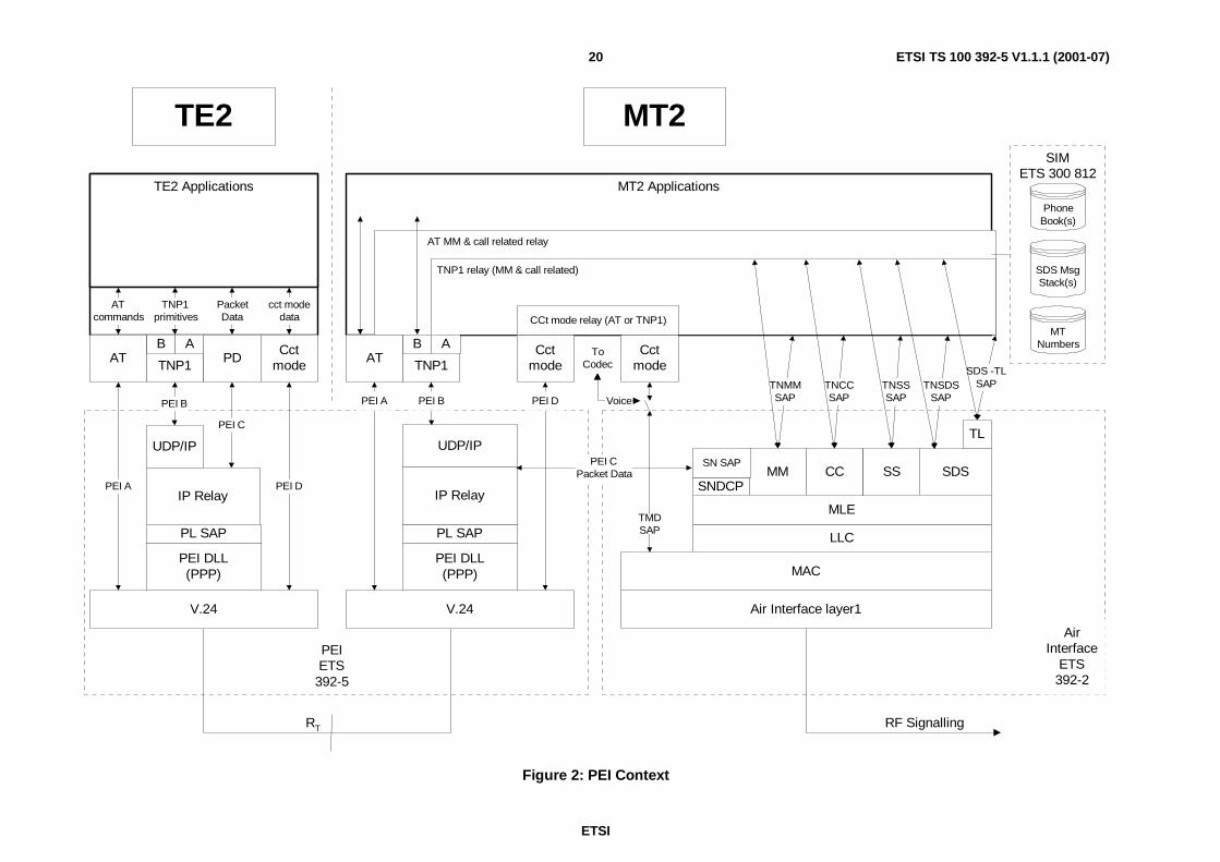
ETSI
ETSI TS 100 392-5 V1.1.1 (2001-07)20
MT2 Applications
AT MM & call related relay
TNP1 relay (MM & call related)
PEIETS
392-5
RF SignallingRT
V.24
Applications
Air Interface layer1
MT2
AT TNP1 PDCct
mode
PEI DPEI A
PEI B
PEI C
MAC
LLC
MLE
V.24
PEI DLL(PPP)
AT TNP1Cct
mode
SNDCPMM CC SDS
Cctmode
TNMMSAP
TNCCSAP
TNSDSSAP
CCt mode relay (AT or TNP1)
SS
TNSSSAP
TE2
UDP/IPTL
SDS -TLSAP
AirInterface
ETS392-2
AB
SIMETS 300 812
SDS MsgStack(s)
PhoneBook(s)
MTNumbers
Voice
ToCodec
AB
TNP1primitives
TE2 Applications
ATcommands
PacketData
cct modedata
PL SAP
PEI DLL(PPP)
UDP/IP
PL SAP
PEI D
TMDSAP
IP Relay
SN SAPPEI CPacket Data
PEI BPEI A
IP Relay
Figure 2: PEI Context

ETSI
ETSI TS 100 392-5 V1.1.1 (2001-07)21
4.4 Void
4.5 SDS Message stacksIncoming and outgoing SDS messages are optionally stored on message stacks in the MT. For the purposes of thepresent document the SDS message stacks are taken to be those defined in the SIM specifications ETS 300 812 [18].The stacks are not necessarily identical to the SIM, as these are typically copied into the MT applications, as the SIMinterface is somewhat slow for real time use. The stacks (or their copies) are used by the MT application to remove anylink with the air interface for the timing of SDS message sending. In some implementations, they may also be used tostore sent and received messages for later review by the Mt or TE applications. This feature is particularly useful for thePEI as the TE and MT can synchronize their stacks by using read and write commands on link establishment.
NOTE 1: The behaviour of the SDS message stacks (SIMs) cannot be changed; they are fixed and linear. If a stackindicates it is full then no more messages can be received from the air interface or from the TE for thatstack. Implementers should try to delete unneeded messages from the MT stack. Methods for determiningthe unneeded messages are outside the scope of the present document.
Indication of incoming messages to any stack may be relayed to applications of the MT, or to the PEI, or both. Thechoice is made by user commands, which set a profile of SDS stack operation. The PEI will use indications, sent to it, toread messages off the stack that are of interest to it (or its application). The TE should take care to read only the numberof messages it can handle without memory overflow. This is especially important with SDS type 4 messages as they cancontain many bytes each. It is an implementation decision as to when to read any subsequent SDS messages.
A summary of some of the SDS message stacks is given here for convenience so that the AT and TNP1 commands canbe put in context, the specifications in ETS 300 812 [18] have priority. Commands sent on the PEI can be used to act onthe messages in the stacks.
NOTE 2: For reference to all SDS stacks within the MT the TE should track the references given to messages (inthe index field) within the MT. When using SDS-TL messaging there is an additional reference within theTL header (message reference), which is also generated within the MT.
The local referencing shall be implemented by exchange of messages at the start of any SDS PEI sequence. To ensurecomplicity of TE and MT references SDS transactions shall be initiated one at a time and use the returned MT referencefor linking further responses. . For SDS-TL this field would be the "message reference". For other SDS transactions thiswould be "SDS instance" for direct messages and the combination of "AI Service" and "Message Index" for messagesthat use the message stacks.
All stacks have up to 255 entries, each of which is made up of several fields. The fields pertinent to the PEI are brieflyexplained below.
4.5.1 Status message texts
For each status value that has been provisioned with a text string this stack holds the status value and the programmedstring. The text string is coded in the SIMs using the default 8-bit alphabet ISO 8859-1 [22].
4.5.2 SDS 1 message texts
For each SDS1 value that has been provisioned with a text string this stack holds the SDS1 value and the programmedstring. The text string is coded in the SIMs using the default 8-bit alphabet ISO 8859-1 [22].
4.5.3 Status and SDS types 1, 2 and 3
Message Index 0 to 65,535, used to identify messages more uniquely than the message pointer (256).
Address Message Destination or Source identifier.
Message Status Message sending and reading status (Received from AI but not read / Received from AI and read/Application originated to be sent / sent).
SDS type Status, SDS Type 1 SDS type 2 SDS type 3.

ETSI
ETSI TS 100 392-5 V1.1.1 (2001-07)22
SwMI Time Defined in 392-2.
User Data Dependant on the SDS type.
NOTE: If the SwMI time is to be used by the TE for outgoing messages it is out of the scope of the presentdocument to define how it is set.
4.5.4 SDS type 4
Message Index 0 to 65,535, used to identify messages more uniquely than the message pointer (256).
Address Message Destination or Source identifier.
Message Status Message sending and reading status (Received from AI but not read/Received from AI and read/Application originated to be sent / sent).
Protocol ID SDS-TL protocol identifier. Defined in 392-2.
Message Header If SDS-TL is used this field is the SDS-TL header (message reference, delivery report request,storage, validity period, service selection, forward address (only in case of storage).
SwMI Time Defined in 392-2.
User Data If SDS-TL protocol is used this field includes the TL header information (e.g. PID and messagereference).
NOTE 1: If the SwMI time is to be used by the TE for outgoing messages it is out of the scope of the presentdocument to define how it is set.
NOTE 2: In AT commands for SDS-TL, the data is structured more like the air interface than the SIM definitions.That is the fields for protocol ID and the TL header are part of the use data. The application developershould understand these fields (see clause 4.8).
4.6 Phone booksThe phone books are also defined in the SIM definitions [18] and the MT may have access to several types of phonebook. In particular there are books for PSTN numbers, TETRA numbers, group numbers and last numbers dialled orreceived.
In the present document TNP1 commands have no access to the phone books. The AT commands have access to aPSTN phone book only, for functionality similar to GSM.
The use of entries in this phone book (e.g. PABX numbers) is outside the scope of the present document.
Future versions of the present document will expand on the access to phone books in the MT.
4.7 Reserved status values considerationsThe routing of all status values shall follow profile settings even if they contain reserved values (including theemergency value 0).
4.8 SDS-TL considerationsThe SDS Transport Layer protocol is fully defined in EN 300 392-2 [2] and is in fact a layer on top of the standard SDStype 4 messages. This is shown in the context model of figure 2. The transport layer protocol elements are contained ina message header and are briefly:
• Protocol Identifier;
• Delivery Report request;
• Service Selection;

ETSI
ETSI TS 100 392-5 V1.1.1 (2001-07)23
• Short Form Report;
• Storage (Store and forward via the SwMI or a service centre);
• Validity Period;
• Message Reference;
• Message Reference Handle (Applicable to TNP1 only as AT commands can only go "one at a time");
• Forward Addressing (Applicable when "storage" is true).
The application developer should understand these features and know that the SDS-TL header elements shall beencoded as part of the user data parameter, both on AT command lines and in TNP1 PDUs.
The "user data" part of a SDS type 4 message includes SDS-TL header information. . Some of the header elementvalues and the treatment of the Transport Layer (TL) protocols should be set by the TE and some by the MT.
Only the application in the TE can know what values to put in some of the TL elements (protocol ID, delivery reportrequest, service selection, storage and validity period). This means the TE manufacturer should understand the transportlayer of SDS type 4 and be able to fill the relevant fields. The SDS-TL is defined in the TETRA air interfacespecification EN 300-392-2 [2] clause 29.
On the other hand the MT shall add the message reference to the data, as they are unique for the air interface, indeedSDS messages could be sent via the MT MMI (especially if the TE was not connected). For this reason the "messagereference" for any given SDS-TL transfer shall be obtained from the MT.
NOTE: When using TNP1 commands the user application may make use of temporary message references(message reference handle). The AT command set does not use this reference, to keep more compatibilitywith GSM. The implication is that when using AT commands a second SDS-TL message cannot be sentuntil the MT has replied with the message identifier.
For store and forward applications there are two sides. The TE application will know if it wants to make use of the storeand forward service centre and should indicate this to the MT. The service availability is sent in an Air Interfacebroadcast from the SwMI. As this may change as the MT roams the MT should forward (at least changes to) thisbroadcast information to the TE in near real time. The MT may still receive messages it cannot process and may have tolook inside SDS-TL headers to confirm valid requests. Both TNP1 and AT commands will have the unsolicitedresponse to carry system broadcast information.
Addressing is especially important for applications that want to send SDS-TL using a store and forward service centre.In this case the called party address field on the AT command line or the TNP1 PDU is that of the service centre. Thefinal address (forward address) of the message is in the user data field. The service centre address can be obtained fromthe MT using AT or TNP1 commands. For details on addressing for store and forward services refer to [2] clause 29.
The SDS-TL transport layer reports will be independent message exchanges, which are linked at the application layerby the SDS-TL "message reference". Local responses to message sending shall not be used to indicate that thedestination user has read the SDS-TL message only that the SDS message has been sent or written to the message stack.
4.9 AT commands
4.9.1 General on AT commands
AT commands are widely used in the IT world as a means of controlling modems from a PC or other intelligentterminal. AT commands have been adopted by many wireless systems as a means for accessing data services(e.g. GSM, CDPD, Mobitex etc.) and are therefore used as a basis in the TETRA PEI to give access to TETRA services.The TETRA services available using AT commands includes call control, mobility management and SDS.
Access to Supplementary Services is not provided in this edition of the present document.
In addition there are commands to access the radio configuration and storage parameters.

ETSI
ETSI TS 100 392-5 V1.1.1 (2001-07)24
Whilst compatibility with existing AT commands is important, it shall be borne in mind that the different servicesoffered, as part of the TETRA specifications, (e.g. half duplex, group addressing and additional SDS services) willnecessarily mean adaptation of the commands as defined in the present document.
The present document also gives AT commands that can be used to set up voice calls.
With reference to figure 2 the AT commands use the PEI A interface for commands.
Subsequent data calls will use the PEI D interface for circuit mode data or PEI C interface for packet data. Voice trafficis not carried over the PEI.
In the classical AT commands model, the MT effectively operates in one of two states, namely "Command" state and"On-line data" state. For the PEI this model has been altered slightly. The "On-line data" state is renamed to "AT circuitmode data" and there has been the addition of the "AT packet data" state. The "AT" is added to differentiate these statesfrom any equivalent states entered by TNP1 commands.
The outline state diagram is shown in figure 3, if there is a conflict between the diagram and text the textual descriptiontakes precedence.
NOTE: When the MT or TE is not in "command state" then AT commands are ignored and only hardware or ESCsequences are recognized.
ATA, CTCC, ATO orATD & CTSD=cct mode
AT CircuitModeData
ATCommand
Hardware,TE - ESC or
MT - NOCARRIER
TNP1 orPacketData
Hardware orPPP Link fail
ATD*99#& WS46
AT commandsignored
AT commandsignored
All exceptATA, CTCC, ATO & ATD
Figure 3: AT Command State Diagram
4.9.2 AT command state
Both TE and MT enter this state on initialization or PEI link establishment (e.g. DTR detection or AT? with OKresponse). It is always entered from on line data state when any ongoing call is cleared or when the TE sends arecognized Escape sequence.
Signalling received from the TE on logical circuit TD (V.24 circuit 103) is treated as command lines and processed bythe MT. The MT command responses and any unsolicited messages are sent to the TE on logical circuit RD (V.24circuit 104).
With reference to figure 2 the signalling is sent on the interface PEI A.
In this state all commands and responses will be accepted and acted on.
ETSI
ETSI TS 100 392-5 V1.1.1 (2001-07)25
This is the state where typically the MT operating modes are set, MM information is received, SDS messages are sentand received and circuit mode calls are established.
Voice call(s) signalling (from the TE or air interface) will lead to a voice call(s) being active in this state.
NOTE 1: It is recommended that any signalling related to the setting up of a circuit mode data call be rejectedduring a voice call maintenance phase as the TD and RD lines are needed for call maintenance and cleardown.
NOTE 2: Voice traffic is NOT carried over the PEI. This would typically be via a microphone and speakerconnected to the MT audio path.
If a voice call is in progress, the MT will monitor the Air Interface for call maintenance and clear down signalling. TheMT will also monitor for loss of connection with the other party(s). The MT will pass appropriate voice callmaintenance and clear down signalling to the TE. The clear down of a voice call by the other party, the SwMI or loss ofRF connection will cause a PEI disconnect signal with the appropriate cause.
The TE will monitor its any MMI actions or other applications and pass appropriate call maintenance and clear downsignalling to the MT.
NOTE 3: If the MT has SDS stacks it is recommended the TE synchronize all the stacks using the "list" and "read"commands, or the "write commands when returning to AT command state.
4.9.3 AT circuit mode data state
A Circuit Mode Data call is in progress whilst in this state.
Signalling received from the TE on logical circuit TD (V.24 circuit 103) is forwarded as data to the appropriatedestination (typically the MT U-Plane for transmission over the TETRA AI).
Circuit mode data destined for the TE is forwarded on logical circuit RD (V.24 circuit 104).
TE transmit flow control may be performed by the circuit CTS (V.24 circuit 106).
TE receive flow control may be performed by the circuit RTS (V.24 circuit 105).
NOTE: RS232 E reuses RTS as Ready For Receiving (RFR) for TE receive flow control.
With reference to figure 2 the signalling is sent on the interface PEI D.
The MT will monitor the Air Interface for call maintenance and clear down signalling.
In this state all AT commands are ignored as the signalling is on PEI D and nothing is routed to the AT entity. The TEEscape sequence from the TE or "NO CARRIER" from the MT may be considered as AT commands and areexceptions, as they will be acted upon. AT commands in this sense include indications of SDS messages that can beconcurrently accepted by the MT (either directly or via the stacks).
4.9.4 TNP1 and packet data state
A TNP1 or Packet Data session is in progress whilst in this state. The correct destination for signalling in eitherdirection is determined by the UDP/IP addressing.
Signalling received from the TE by the MT on logical circuit TD (V.24 circuit 103) is forwarded as data to theappropriate destination (typically the TNP1 relay or SNDCP for transmission over the TETRA AI). All AT commandsare ignored in this state. AT commands in this sense include indications of SDS messages that can be concurrentlyaccepted by the MT (either directly or via the stacks).
Signalling destined for the TE from the MT (TNP1 or packet data) is forwarded on logical circuit RD (V.24circuit 104).
With reference to figure 2 the signalling is sent on the interface PEI B or PEI C.
This state has two sub-states called "local" and "wide". The local sub-state is one where the MT has no context activetowards the SwMI. The wide sub-state is one where the MT has a context active towards the SwMI.

ETSI
ETSI TS 100 392-5 V1.1.1 (2001-07)26
4.9.5 Transitions between states
4.9.5.1 Transition from AT command state to AT circuit mode data state
The AT Circuit Mode Data state is entered from AT Command as indicated below:
1) To initiate an outgoing circuit mode data call the TE sends a valid ATD command on logical circuit TD, wherethe previous +CTSDC command had defined the circuit mode data call parameters.
2) To accept an incoming circuit mode data call the TE sends a CTCC command on logical circuit TD, where thecall set up signalling indicated a circuit mode data call.
3) For compatibility with GSM AT commands an incoming call may be answered with the ATA command. If theTE accepts all call parameters (e.g. number of slots) set by the incoming signalling.
4) For an ongoing circuit mode data call that has been interrupted by the TE Escape sequence the TE can send theATO command to resume the interrupted call.
4.9.5.2 Transition from AT circuit mode data state to AT command state
The AT circuit mode data state is always left for AT Command, in one of four ways. The first two are only available ifthe hardware connection has circuits 108 and 109. Options 3 and 4 are only viable if the MT and TE both support theHayes improved escape sequence with guard time. If hardware lines are used, the sending of "ESC" or "NOCARRIER"is optional.
1) The TE turns circuit 108 off (DTR, behaviour set using "&D" command).
2) The MT turns circuit 109 off (DCD, behaviour set using "&C" command).
3) The TE sends a complete, special "escape" sequence with timing constrictions (e.g. "<guard delay> +++ <guarddelay>") on logical circuit TD.
4) The MT sends a special "<guard delay> NO CARRIER <guard delay>" unsolicited response on logical circuitRD.
NOTE: This method is not in any existing standard but is in the "industry standard" Hayes AT User Manual. Itshould only be used if the hardware circuits are not available.
4.9.5.3 Transition from AT command state to TNP1 or packet data state
The TNP1 or Packet Data state is entered from AT Command, for TNP1 link establishment or outgoing packet datacontext activation, as indicated below. Note only outgoing packet data context creation is possible:
1) The IP addressing to be used (wide or local) is set using the +WS46 command..
2) The TE sends ATD*99# on logical circuit TD. After the MT sends "CONNECT" the MT and TE negotiate aPPP link by transmitting LCP datagrams on logical circuits TD and RD. The IP addresses negotiated aredetermined by the previous +WS46 command according to table 2.
4.9.5.4 Transition from TNP1 and packet data state to AT command state
1) The TE turns circuit 108 off (DTR, behaviour set using "&D" command).
2) The MT turns circuit 109 off (DCD, behaviour set using "&C" command).
3) Either the TE or MT in the DLL closes the PPP link.

ETSI
ETSI TS 100 392-5 V1.1.1 (2001-07)27
4.10 TNP1 and IP network layer
4.10.1 General operation
In order to transfer messages over the PEI, TNP1 uses the services of UDP/IP, IP Relay and the PEI DLL. The DLLused is PPP, which is defined in RFC 1661 [12]. The network layer is established in accordance with RFC 1662 [13].The MT should be able to support all options to allow for different TE connections. This issue of the present documentdoes not define a list of required options. Implementers should check for supported options of different suppliersthrough the MoU processes.
For TNP1 to operate, an IP connection between MT2 and TE2 has to be established. The exact mode of network layerestablishment is outside the scope of the present document but is based on the PPP and UDP/IP combination. Afterreceiving an administrative open event from the service user the TNP1 entity, as a kind of IP application, should ask fora socket from the IP service task. From this point the TNP1 entity is ready for service.
The TNP1 signalling is carried via a dedicated UDP port.
NOTE: A Port number shall be obtained from the IANA.
The context of the network layer and its SAPs in the overall PEI is shown in figure 2.
4.10.2 IP addressing
There are two modes of IP operation supported by the PEI. Each mode has different addressing requirements asdescribed below. In total the TE/MT combination needs three different addresses.
1) "TE IP". This is a fixed IP address used by all TEs its value is 10.0.0.100.
2) "MT IP". This is a fixed IP address used by all MTs its value is 10.0.0.101.
3) "MS IP". This is a dynamic address given to the MT by the SwMI on context activation.
These addresses are used differently in the two modes described below:
1) In both modes IP packets from the TE2 to MT2 internal applications have to use the <MT-IP> address.
2) The default mode for the MT is "wide".
4.10.3 Local mode
In this mode TNP1 runs over the PEI and is used solely for control of the radio and call processing. Al services areavailable to TNP1 except packet data transfer. As TNP1 runs over UDP/IP it still needs an IP address at both the TE andMT in order to communicate. The addresses used are the two static addresses "TE IP" and "MT IP". These addresses areset on link establishment. To allow for a connection of equipment (e.g. PC) that does not know the static address thelink can be established using dynamic address techniques but the address given is always "TE IP". The MS shall knowif the TE wants local (TNP1) operation or wide (packet data transfer, with or without TNP1) to know whether to give"TE IP" or "MS IP". The TE shall use the AT command WS46 to set whether the TE wants a local connection or a wideconnection (wide is the default).
The use of source and destination addresses for the different local communications is shown in table 1.
Table 1: Local mode address use
Comms / Address TE2->MT2 MT2->TE2 TE2->XXX(note 1)
XXX->TE2(note 1)
MT2->XXX(note 2)
XXX->MT2(note 2)
Source Address TE IP MT IP N/A N/A N/A N/ADestination Address MT IP TE IP N/A N/A N/A N/AUDP/IP port TNP1 TNP1 N/A N/A N/A N/ANOTE 1: These packets will be discarded by the MT.NOTE 2: These transactions are not applicable to the PEI.
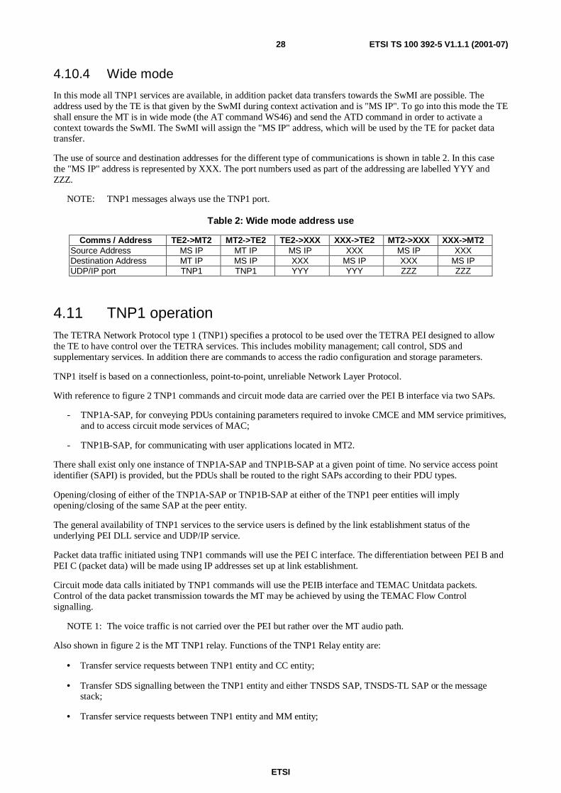
ETSI
ETSI TS 100 392-5 V1.1.1 (2001-07)28
4.10.4 Wide mode
In this mode all TNP1 services are available, in addition packet data transfers towards the SwMI are possible. Theaddress used by the TE is that given by the SwMI during context activation and is "MS IP". To go into this mode the TEshall ensure the MT is in wide mode (the AT command WS46) and send the ATD command in order to activate acontext towards the SwMI. The SwMI will assign the "MS IP" address, which will be used by the TE for packet datatransfer.
The use of source and destination addresses for the different type of communications is shown in table 2. In this casethe "MS IP" address is represented by XXX. The port numbers used as part of the addressing are labelled YYY andZZZ.
NOTE: TNP1 messages always use the TNP1 port.
Table 2: Wide mode address use
Comms / Address TE2->MT2 MT2->TE2 TE2->XXX XXX->TE2 MT2->XXX XXX->MT2Source Address MS IP MT IP MS IP XXX MS IP XXXDestination Address MT IP MS IP XXX MS IP XXX MS IPUDP/IP port TNP1 TNP1 YYY YYY ZZZ ZZZ
4.11 TNP1 operationThe TETRA Network Protocol type 1 (TNP1) specifies a protocol to be used over the TETRA PEI designed to allowthe TE to have control over the TETRA services. This includes mobility management; call control, SDS andsupplementary services. In addition there are commands to access the radio configuration and storage parameters.
TNP1 itself is based on a connectionless, point-to-point, unreliable Network Layer Protocol.
With reference to figure 2 TNP1 commands and circuit mode data are carried over the PEI B interface via two SAPs.
- TNP1A-SAP, for conveying PDUs containing parameters required to invoke CMCE and MM service primitives,and to access circuit mode services of MAC;
- TNP1B-SAP, for communicating with user applications located in MT2.
There shall exist only one instance of TNP1A-SAP and TNP1B-SAP at a given point of time. No service access pointidentifier (SAPI) is provided, but the PDUs shall be routed to the right SAPs according to their PDU types.
Opening/closing of either of the TNP1A-SAP or TNP1B-SAP at either of the TNP1 peer entities will implyopening/closing of the same SAP at the peer entity.
The general availability of TNP1 services to the service users is defined by the link establishment status of theunderlying PEI DLL service and UDP/IP service.
Packet data traffic initiated using TNP1 commands will use the PEI C interface. The differentiation between PEI B andPEI C (packet data) will be made using IP addresses set up at link establishment.
Circuit mode data calls initiated by TNP1 commands will use the PEIB interface and TEMAC Unitdata packets.Control of the data packet transmission towards the MT may be achieved by using the TEMAC Flow Controlsignalling.
NOTE 1: The voice traffic is not carried over the PEI but rather over the MT audio path.
Also shown in figure 2 is the MT TNP1 relay. Functions of the TNP1 Relay entity are:
• Transfer service requests between TNP1 entity and CC entity;
• Transfer SDS signalling between the TNP1 entity and either TNSDS SAP, TNSDS-TL SAP or the messagestack;
• Transfer service requests between TNP1 entity and MM entity;

ETSI
ETSI TS 100 392-5 V1.1.1 (2001-07)29
• Transfer circuit mode data and flow control indication between TNP1 entity and TMD SAP.
Routing of service requests between MT2 user applications and CMCE and MM entities is outside the scope of thepresent document. Similarly, rules for decision of which user application, located either in MT2 or ET2, shall handle theservice primitives is outside the scope of the present document.
TNP1R is defined in order to clarify the relationship between the TNP1 protocol and MT2 services. The TNP1R-SAP isnot intended to be a testable boundary.
NOTE 2: Implementation of any of the TNP1 PDUs is optional.
4.12 Link start up at the MTFollowing common industry practice the PEI will always start in AT mode. Link establishment can be determined usingthe hardware signals (DTR, DSR) or by the TE sending "AT?" and receiving an "OK" response.
If the TE wants to use TNP1 it shall issue AT commands to start the UDP/IP link establishment in wide or local mode.For example, to go into wide TNP1 mode these would be WS46 = 14 followed by ATD*99#. The TNP1 link would beestablished as described in clause 6.8.4.3 negotiating the wide IP address.
NOTE 1: The default is "wide" mode, the WS46 = 14 command is strictly only needed if the local mode waspreviously selected.
NOTE 2: If the MT has SDS stacks it is recommended the TE synchronize all the stacks using the "list" and "read"commands, or the "write commands when the PEI link is established.
5 Physical layer
5.1 General on physical layerThis clause recommends the physical layers that should be used between a Terminal Equipment (TE) and a MobileTermination (MT) at the TETRA reference point RT. The TE represents a DTE. The MT represents a DCE.
The present document defines a point-to-point configuration using a sub-set of ITU-T Recommendation V.24 [4] andITU-T Recommendation V.28 [6]. In addition to the electrical level it defines physical connection pin numbers forcertain widely used connector types, and the lowest layer transmission format for ITU-T Recommendations V.24 andV.28.
NOTE: The TE and MT shall have a minimum requirement of a hardware buffered UART on the serial port, toavoid loss of characters if the software is slow to read the incoming characters.
5.2 Electrical characteristicsThe electrical characteristics should follow ITU-T Recommendation V.28 [6] for unbalanced signalling. Environmentsof high electrical noise may force implementers to adopt other electrical characteristics.
5.3 Physical connectionThe present document does not specify the physical connection to be used at the interface. However, it is recommendedthat the MT presents a standard or commonly used interface to the TE (e.g. female DB-9 or RJ45). This may bepresented via a MT specific cable.
If a D type connector is used, then it may be either a 25-pole or a 9-pole connector (receptacle).
If RJ11/RJ45 type connector is used, then it may be a 10-pole or 8-pole connector.

ETSI
ETSI TS 100 392-5 V1.1.1 (2001-07)30
The pin assignment of the supported sub-set of V.24 signals to 9 way and 25 way D type connectors is shown in table 3,refer to ITU-T Recommendation V.24 [4] and ITU-T Recommendation V.28 [6]. The pin assignment follows currentindustry recommendations.
Table 3: V.24 interface pin assignment for Submin-D type connector
Circuit Signal Abbreviation Submin-D typeNumber 9-pole 25-pole
101 Protective ground PG Screen Screen + 1102 Signal ground SG 5 7
103 Transmitted Data TD 3 2104 Received Data RD 2 3
105 Request to Send RTS 7 4106 Ready for sending (Clear to Send) CTS 8 5107 Data Set Ready DSR 6 6
108/2 Data Terminal Ready DTR 4 20109 Data Channel received line signal
DetectorDCD 1 8
125 Ring Indicator RI 9 22NOTE 1: The signal RTS may be reused as RFR according to RS232E.NOTE 2: The Ring Indicator signal is not used in this version of the document. The circuit is
reserved for possible future use.
The pin assignment of a sub-set of V.24 signals to RJ11/RJ45 type connectors is shown in table 4. The 8 poleassignments are given in RS232D.
Table 4: V.24 interface pin assignment for RJ11/RJ45 type connector
Circuit Signal Abbreviation RJ11/RJ45Number 8-pole 10-pole
101 Protective ground PG102 Signal ground SG 4
103 Transmitted Data TD 6104 Received Data RD 5
105 Request to Send RTS 8106 Clear to Send CTS 7107 Data Set Ready DSR 1
108/2 Data Terminal Ready DTR 3109 Data Channel received
line signal DetectorDCD 2
NOTE 3: The Ring Indicator signal does not have a pin assigned for the 8-pole RJ11/45 connector.
5.4 Character formatTo enable fully transparent data transmission an 8-bit character format shall be used by default. In 8-bit format,characters are transmitted asynchronously with 1 start bit and 1 stop bit. No bit is used for parity checking. The 8-bitcode is identified by b8, b7, b6, b5, b4, b3, b2 and b1, where b8 is the most-significant bit (MSB) and b1 is theleast-significant bit (LSB). The bit combinations represent integer in the range 0 to 255 where b8 has a weight of 128
and b1 has a weight of 1.
The least-significant bit b1 of the character is transmitted first.
The character format in the asynchronous operation is shown in figure 4.

ETSI
ETSI TS 100 392-5 V1.1.1 (2001-07)31
Binary 1binary 0 ST b1 b2 b3 b4 b5 b6 b7 b8 SP
Start bit Stop bit
Figure 4: Asynchronous character transmission
Whilst the default is 8, N, 1 a MT may support other character formats, which a TE2 may select using the AT-command+ICF.
5.5 Data transmission rateITU-T Recommendation V.28 [6] shall apply. This generally defines signalling rates below 20 kbit/s, however underspecific conditions described in annex A of [6], operation up to 115 kbit/s is possible.
The MT should be able to accept commands initially at 9 600 bit/s, as recommended in [5], and optionally be able toautomatically detect the baud rate up to 115 kbit/s at the physical layer. Automatic baud rate detection at theestablishment of the AT link needs the TE to transmit a sequence of redundant characters (e. g. "AT?") whilst waitingfor a valid response (e. g. "OK").
6 AT command set
6.1 General on AT command setThis clause defines a profile of AT commands that may optionally be used in the PEI for controlling MT functions andTETRA network services from a TE. Whilst the whole clause is optional some commands have an "implementation"attribute of mandatory or optional. This attribute is conditional on the AT command set being implemented at all. In anycase all the TETRA related commands should be implemented if the AT commands are implemented. Optionalcommands relate to the setting up of PEI parameters (e.g. S commands).
The terminology in relation to calls is that found in TETRA specifications.
Commands from [5] and existing digital cellular standards [8] and [9] are used whenever applicable.
The command prefixes "+C" for Digital Cellular are reserved as extensions to the basic command set in [5]. The presentdocument uses the similar command prefixes and syntax to construct TETRA commands. Some existing commandshave been taken as a basis and extended to include TETRA features. Some commands are specific to TETRA and so arenew commands but use the "+C" prefix.
These AT commands allow access to voice, SDS, packet data and circuit data services.
6.2 LimitationsThe AT implementation has the following limitations:
• Supplementary Services are not supported in the present document.
• The maximum length of a single line will be limited to that of the longest command (SDS-TL).
• AT commands can only be used when the TE and MT are both in the AT command state.
• All addressing digits in the command line are to be IRA characters.
• SDS, MM and MT status commands can be made during a voice call.
• The TE shall wait for a PEI response to an SDS message sending before sending another.
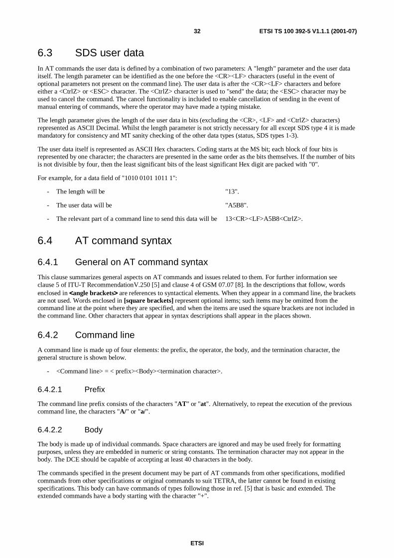
ETSI
ETSI TS 100 392-5 V1.1.1 (2001-07)32
6.3 SDS user dataIn AT commands the user data is defined by a combination of two parameters: A "length" parameter and the user dataitself. The length parameter can be identified as the one before the <CR><LF> characters (useful in the event ofoptional parameters not present on the command line). The user data is after the <CR><LF> characters and beforeeither a <CtrlZ> or <ESC> character. The <CtrlZ> character is used to "send" the data; the <ESC> character may beused to cancel the command. The cancel functionality is included to enable cancellation of sending in the event ofmanual entering of commands, where the operator may have made a typing mistake.
The length parameter gives the length of the user data in bits (excluding the <CR>, <LF> and <CtrlZ> characters)represented as ASCII Decimal. Whilst the length parameter is not strictly necessary for all except SDS type 4 it is mademandatory for consistency and MT sanity checking of the other data types (status, SDS types 1-3).
The user data itself is represented as ASCII Hex characters. Coding starts at the MS bit; each block of four bits isrepresented by one character; the characters are presented in the same order as the bits themselves. If the number of bitsis not divisible by four, then the least significant bits of the least significant Hex digit are packed with "0".
For example, for a data field of "1010 0101 1011 1":
- The length will be "13".
- The user data will be "A5B8".
- The relevant part of a command line to send this data will be 13<CR><LF>A5B8<CtrlZ>.
6.4 AT command syntax
6.4.1 General on AT command syntax
This clause summarizes general aspects on AT commands and issues related to them. For further information seeclause 5 of ITU-T RecommendationV.250 [5] and clause 4 of GSM 07.07 [8]. In the descriptions that follow, wordsenclosed in <<<<angle brackets>>>> are references to syntactical elements. When they appear in a command line, the bracketsare not used. Words enclosed in [square brackets] represent optional items; such items may be omitted from thecommand line at the point where they are specified, and when the items are used the square brackets are not included inthe command line. Other characters that appear in syntax descriptions shall appear in the places shown.
6.4.2 Command line
A command line is made up of four elements: the prefix, the operator, the body, and the termination character, thegeneral structure is shown below.
- <Command line> = < prefix><Body><termination character>.
6.4.2.1 Prefix
The command line prefix consists of the characters "AT" or "at". Alternatively, to repeat the execution of the previouscommand line, the characters "A/" or "a/".
6.4.2.2 Body
The body is made up of individual commands. Space characters are ignored and may be used freely for formattingpurposes, unless they are embedded in numeric or string constants. The termination character may not appear in thebody. The DCE should be capable of accepting at least 40 characters in the body.
The commands specified in the present document may be part of AT commands from other specifications, modifiedcommands from other specifications or original commands to suit TETRA, the latter cannot be found in existingspecifications. This body can have commands of types following those in ref. [5] that is basic and extended. Theextended commands have a body starting with the character "+".

ETSI
ETSI TS 100 392-5 V1.1.1 (2001-07)33
6.4.2.3 Termination Character
The termination character is defined with the S3 register. The default value is <CR> (IRA 13).
6.4.3 Command Types
AT commands can have up to four different forms, indicated by an operator within the command body, defined below.
1) Execution: A command that has no parameters will have a body containing no operator at all. The MT willexecute the command and any response returned. Some basic commands have no operator but nonethelessperform a "set" operation. Examples are ATA where no parameters are available and &D1 where the "1" is avalue equivalent to a "set".
2) Set: A command body containing the operator "=" is used in two ways. It can either be used to "set" a parameterby storing a value or values for later use. Alternatively it can be used as an execution; that is to invoke aparticular function of the equipment together with parameters needed as part of that function. Examples areATS3=13 which sets the S3 parameter to <CR> and +CMSGL = <SDS status> which will read a list of SDSmessages.
3) Test: A command body containing the operator "=?" is used to determine if the MT supports the command formthe TE. The MT will return "OK" if the command is supported. If there are supported parameters associated withthis command the range of values will be returned as well.
4) Read: A command body containing the operator "?" will return the value or values of any stored parametersrelated to that command.
6.4.4 Parameters
Set and read command types have an associated list of parameters, some are mandatory and some are optional. Optionalparameters shall be treated in order. Parameters can be omitted if their place is "staked" by the ",". Trailing parametersand their "," can be omitted completely providing there are no more parameters. Any unused or omitted optionalparameters shall be set to default values.
6.4.5 Examples
ATCMD1<CR> (basic execution command).
AT+CMD3=,15<CR> (extended set command with two leading optional parameters omitted).
AT+CMD3? <CR> (read command to get parameter values).
AT+CMD3=? <CR> (test command returns OK if supported and range of parameters).
6.4.6 Information responses and result codes
6.4.6.1 General on information responses and result codes
The MT responses should follow the definitions in [5]. They may be "verbose" or "numeric", as set by the "V"command. There are two types of responses that may be issued by the MT: information text and result codes.
Both consist of three parts: a header, text or result, and a trailer. The characters transmitted for the header aredetermined by a user setting (see the V command). In verbose mode the trailer consists of two characters, being thecharacter having the ordinal value of parameter S3 followed by the character having the ordinal value of parameter S4.
6.4.6.2 Information Responses
Information results have text only after the header. The result text may be transmitted as a number or as a string,depending on a user-selectable setting (see the V command).
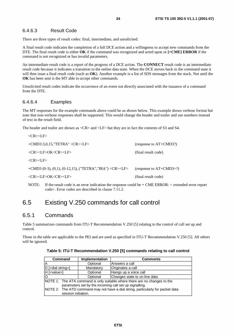
ETSI
ETSI TS 100 392-5 V1.1.1 (2001-07)34
6.4.6.3 Result Code
There are three types of result codes: final, intermediate, and unsolicited.
A final result code indicates the completion of a full DCE action and a willingness to accept new commands from theDTE. The final result code is either OK if the command was recognized and acted upon or [+CME] ERROR if thecommand is not recognized or has invalid parameters.
An intermediate result code is a report of the progress of a DCE action. The CONNECT result code is an intermediateresult code because it indicates a transition to the online data state. When the DCE moves back to the command state itwill then issue a final result code (such as OK). Another example is a list of SDS messages from the stack. Not until theOK has been sent is the MT able to accept other commands.
Unsolicited result codes indicate the occurrence of an event not directly associated with the issuance of a commandfrom the DTE.
6.4.6.4 Examples
The MT responses for the example commands above could be as shown below. This example shows verbose format butnote that non-verbose responses shall be supported. This would change the header and trailer and use numbers insteadof text in the result field.
The header and trailer are shown as <CR> and <LF> but they are in fact the contents of S3 and S4.
<CR><LF>
+CMD3:3,0,15,"TETRA" <CR><LF> (response to AT+CMD3?)
<CR><LF>OK<CR><LF> (final result code)
<CR><LF>
+CMD3 (0-3), (0,1), (0-12,15), ("TETRA","IRA") <CR><LF> (response to AT+CMD3=?)
<CR><LF>OK<CR><LF> (final result code)
NOTE: If the result code is an error indication the response could be + CME ERROR: < extended error reportcode>. Error codes are described in clause 7.11.2.
6.5 Existing V.250 commands for call control
6.5.1 Commands
Table 5 summarizes commands from ITU-T Recommendation V.250 [5] relating to the control of call set up andcontrol.
Those in the table are applicable to the PEI and are used as specified in ITU-T Recommendation V.250 [5]. All otherswill be ignored.
Table 5: ITU-T Recommendation V.250 [5] commands relating to call control
Command Implementation CommentsA Optional Answers a callD [<dial string>] Mandatory Originates a callH [<value>] Optional Hangs up a voice callO Optional Changes state to on line dataNOTE 1: The ATA command is only suitable where there are no changes to the
parameters set by the incoming call set up signalling.NOTE 2: The ATD command may not have a dial string, particularly for packet data
session initiation.

ETSI
ETSI TS 100 392-5 V1.1.1 (2001-07)35
6.5.2 Result Codes
Note the result codes for the existing AT "D" and "A" commands may differ from those specified in ITU-TRecommendation V.250 [5]. In particular the TETRA result codes will be used to indicate the progress of an outgoingcall, as the number of parameters is completely different from those envisaged in ITU-T Recommendation V.250 [5]. Insome special cases the standard final result codes are allowed, these are indicated in table 6. All other cases should usethe TETRA related commands.
Table 6: ITU-T Recommendation V.250 [5] results relating to call control
Result Code CommentsBUSY Engaged signal detectedCONNECT <text> Issued if the call is connected with no change to call
parameters. <text> is manufacturer specific and mayinclude line speed, data compression etc.
ERROR Command line not recognized or illegal parametersNO CARRIER Issued as a result for ATD if the MT is out of coverageNO DIAL TONE MT is out of service (e. g. coverage)OK Command successfully executed
6.5.3 Dialled string
The allowed digits associated with the "D" command are:
- "0 1 2 3 4 5 6 7 8 9 * # +". Implementation of these characters is mandatory for TETRA.
The address type can be changed by the +CTSDC or +CTSDS commands. For details of numbering see the latestversion of ETR 300-5 [25].
The SNA shall contain 1 to 3 decimal digits.
The SSI shall contain 1 to 8 decimal digits. Any leading zeros of the SSI shall be suppressed.
The TSI shall contain 8 to 15 decimal digits. The most significant 3 represent the mobile country code (MCC), the next4 represent the Mobile network code (MNC) and the last 1 to 8 represent the short subscriber identity part (SSI)Leading zeroes shall be present.
The external subscriber number shall be a number as defined in ITU-T Recommendation E.164 [16].
6.6 Existing V.250 commands for PEI controlTable 7 summarizes commands from ITU-T Recommendation V.250 [5] relating to the formatting of commands andresponses as well as the PEI hardware interface operation.
Those in the table are applicable to the PEI and are used as specified in [5]. All others will be rejected.

ETSI
ETSI TS 100 392-5 V1.1.1 (2001-07)36
Table 7: ITU-T Recommendation V.250 [5] commands relating to TETRA PEI
Command Implementation. CommentsS0=[<value>] Optional Sets the number of call indications (rings) when the MT
will automatically answer the call. Zero disablesautomatic answering and is the default.
S3=[<value>] Mandatory Command line termination character (mandatory defaultsetting IRA 13 <cr>)
S4=[<value>] Mandatory Response formatting character (recommended defaultIRA 10 <lf>)
S5=[<value>] Mandatory Command line editing character (recommended defaultIRA 8 <backspace>)
E[<value>] Mandatory Command echo (recommended default 1 i.e. MT echoescommands back)
Q[<value>] Mandatory Result code suppression (recommended default 0 i.e. MTtransmits result codes)
V[<value>] Mandatory MT response format (recommended default 1i.e. verbose format)
X[<value>] Optional Defines CONNECT result code format; any added text(values 1-3) is manufacturer specific.
&C[<value>] Optional Determines how logical circuit 109 – Data Channelreceived line signal Detector (DCD) relates to thedetection of received line signal from remote end(recommended default 1 i.e. logical circuit RLSDoperation relates to detection of received signal)(see note)
&D[<value>] Optional Determines how MT responds when logical circuit 108/2Data Terminal Ready (DTR) is changed from ON to OFFcondition during either packet or circuit mode data state(recommended default 2 i.e. change causes MT todisconnect the call, return to command mode and returnthe result "OK") (see note)
+IFC=[<by_te> [,<by_ta>]]
Optional TE-MT local flow control (recommended default 2,2i.e. TE uses RTS (circuit 105) and MT uses CTS (circuit106))
+IPR=[<value>] Optional Sets a fixed PEI data rate if Auto baud rate detection isnot supported (recommended default 0 i.e. automaticdetection).
+ICF=[<format>[,<parity>]]
Optional PEI character framing (recommended default 3,3i.e. eight data bits, no parity, 1 stop bit)
NOTE: This command is not supported if the PEI uses a 4-pin connector.
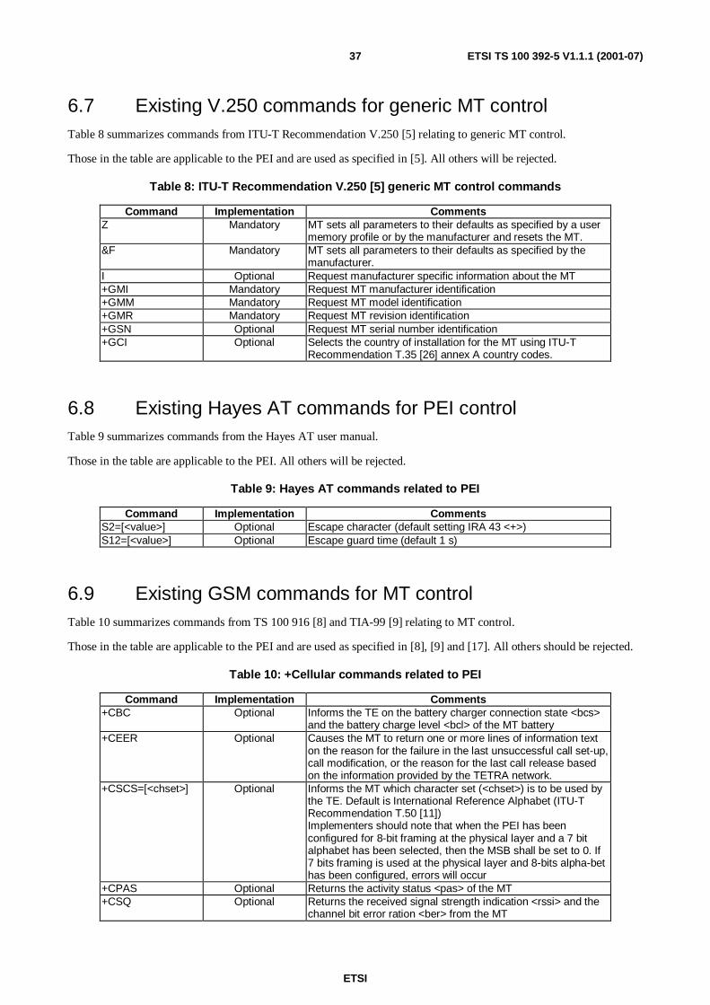
ETSI
ETSI TS 100 392-5 V1.1.1 (2001-07)37
6.7 Existing V.250 commands for generic MT controlTable 8 summarizes commands from ITU-T Recommendation V.250 [5] relating to generic MT control.
Those in the table are applicable to the PEI and are used as specified in [5]. All others will be rejected.
Table 8: ITU-T Recommendation V.250 [5] generic MT control commands
Command Implementation CommentsZ Mandatory MT sets all parameters to their defaults as specified by a user
memory profile or by the manufacturer and resets the MT.&F Mandatory MT sets all parameters to their defaults as specified by the
manufacturer.I Optional Request manufacturer specific information about the MT+GMI Mandatory Request MT manufacturer identification+GMM Mandatory Request MT model identification+GMR Mandatory Request MT revision identification+GSN Optional Request MT serial number identification+GCI Optional Selects the country of installation for the MT using ITU-T
Recommendation T.35 [26] annex A country codes.
6.8 Existing Hayes AT commands for PEI controlTable 9 summarizes commands from the Hayes AT user manual.
Those in the table are applicable to the PEI. All others will be rejected.
Table 9: Hayes AT commands related to PEI
Command Implementation CommentsS2=[<value>] Optional Escape character (default setting IRA 43 <+>)S12=[<value>] Optional Escape guard time (default 1 s)
6.9 Existing GSM commands for MT controlTable 10 summarizes commands from TS 100 916 [8] and TIA-99 [9] relating to MT control.
Those in the table are applicable to the PEI and are used as specified in [8], [9] and [17]. All others should be rejected.
Table 10: +Cellular commands related to PEI
Command Implementation Comments+CBC Optional Informs the TE on the battery charger connection state <bcs>
and the battery charge level <bcl> of the MT battery+CEER Optional Causes the MT to return one or more lines of information text
on the reason for the failure in the last unsuccessful call set-up,call modification, or the reason for the last call release basedon the information provided by the TETRA network.
+CSCS=[<chset>] Optional Informs the MT which character set (<chset>) is to be used bythe TE. Default is International Reference Alphabet (ITU-TRecommendation T.50 [11])Implementers should note that when the PEI has beenconfigured for 8-bit framing at the physical layer and a 7 bitalphabet has been selected, then the MSB shall be set to 0. If7 bits framing is used at the physical layer and 8-bits alpha-bethas been configured, errors will occur
+CPAS Optional Returns the activity status <pas> of the MT+CSQ Optional Returns the received signal strength indication <rssi> and the
channel bit error ration <ber> from the MT
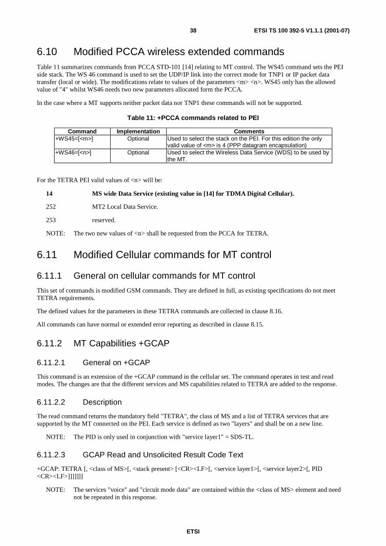
ETSI
ETSI TS 100 392-5 V1.1.1 (2001-07)38
6.10 Modified PCCA wireless extended commandsTable 11 summarizes commands from PCCA STD-101 [14] relating to MT control. The WS45 command sets the PEIside stack. The WS 46 command is used to set the UDP/IP link into the correct mode for TNP1 or IP packet datatransfer (local or wide). The modifications relate to values of the parameters <m> <n>. WS45 only has the allowedvalue of "4" whilst WS46 needs two new parameters allocated form the PCCA.
In the case where a MT supports neither packet data nor TNP1 these commands will not be supported.
Table 11: +PCCA commands related to PEI
Command Implementation Comments+WS45=[<m>] Optional Used to select the stack on the PEI. For this edition the only
valid value of <m> is 4 (PPP datagram encapsulation)+WS46=[<n>] Optional Used to select the Wireless Data Service (WDS) to be used by
the MT.
For the TETRA PEI valid values of <n> will be:
14 MS wide Data Service (existing value in [14] for TDMA Digital Cellular).
252 MT2 Local Data Service.
253 reserved.
NOTE: The two new values of <n> shall be requested from the PCCA for TETRA.
6.11 Modified Cellular commands for MT control
6.11.1 General on cellular commands for MT control
This set of commands is modified GSM commands. They are defined in full, as existing specifications do not meetTETRA requirements.
The defined values for the parameters in these TETRA commands are collected in clause 8.16.
All commands can have normal or extended error reporting as described in clause 8.15.
6.11.2 MT Capabilities +GCAP
6.11.2.1 General on +GCAP
This command is an extension of the +GCAP command in the cellular set. The command operates in test and readmodes. The changes are that the different services and MS capabilities related to TETRA are added to the response.
6.11.2.2 Description
The read command returns the mandatory field "TETRA", the class of MS and a list of TETRA services that aresupported by the MT connected on the PEI. Each service is defined as two "layers" and shall be on a new line.
NOTE: The PID is only used in conjunction with "service layer1" = SDS-TL.
6.11.2.3 GCAP Read and Unsolicited Result Code Text
+GCAP: TETRA [, <class of MS>[, <stack present> [<CR><LF>[, <service layer1>[, <service layer2>[, PID<CR><LF>]]]]]]]
NOTE: The services "voice" and "circuit mode data" are contained within the <class of MS> element and neednot be repeated in this response.

ETSI
ETSI TS 100 392-5 V1.1.1 (2001-07)39
6.11.3 Network registration +CREG
6.11.3.1 General on +CREG
This command is an extension of the +CREG command in the cellular set. The command operates in test, set and readmodes. The changes are in the response format. GSM has different location area definitions.
6.11.3.2 CREG Set Syntax
+CREG=<Reg unsolic>
6.11.3.3 Description
The set command controls the sending of an unsolicited result code by the value of <Reg unsolic>, typically reportedwhen there is a change in the MT network registration status or location area.
6.11.3.4 CREG Read and Unsolicited Result Code Text
+CREG: <Reg stat>[, <LA>[, <MNI>]]
6.11.4 Get MT TETRA identities +CNUM
6.11.4.1 General on +CNUM
This command is an extension of the +CNUM command in the cellular set. The command can only operate in test andread modes. The difference from GSM is that GSM specific parameters of speed, service and information transfercapability do not apply. In addition TETRA has different types of number, different values and the numbers themselveshave different formats.
6.11.4.2 Description
The response to this command returns the TETRA subscriber identity number(s) programmed in the MT. If there ismore than one number stored in the MT (e.g. groups and gateways) then each number will be returned on a separateline. There will always be an individual number returned but additional addresses such as groups will vary. Note thevariable used for the identity is "Called party Identity". The "Num type" variable is different from the "called partytype" as it can distinguish groups, gateways and external subscriber numbers. The identity returned will be linked to thetype of number defined by "Num type".
6.11.4.3 CNUM Read Result Code Text
+CNUM: <Num type>, <Called Party Identity>[, <alpha>]<CR><LF>
[<Num type>[, <Called Party Identity>[, <alpha>]]]
6.12 Modified GSM SDS message stack commands
6.12.1 General on Modified GSM SDS message stack commands
The commands for use with the TETRA SDS are based on those used in the GSM Short Message Service (SMS)TS 100 585 [7]. Fields and their contents cannot be identical but the same command names are used to easeunderstanding by GSM application developers. The GSM standard has different modes of operation for SMS messagehandling (block, PDU and text), these are for backward compatibility within GSM and as such are not applicable toTETRA. There is also a difference in the storage between GSM and TETRA. TETRA SDS message storage is based onthe SDS services, whilst GSM has "preferred storage". For these reasons the contents of GSM and TETRA commandsare necessarily different.

ETSI
ETSI TS 100 392-5 V1.1.1 (2001-07)40
In order to support all values of all information elements and user data types a TETRA special mixed mode is used inwhich parameters are conveyed in text and the user data part is conveyed in HEX string. The HEX string is preceded bya length parameter and the command is initiated by a <Ctrl - Z> or cancelled by a <ESC>.
The defined values for the parameters in these TETRA commands are collected in clause 6.17.
All commands can have normal or extended error reporting as described in clause 6.15.13.3.
All new incoming SDS messages onto any of the SDS stacks are indicated to the TE by the +CMTI command.
NOTE: Throughout this clause the <AI service> variable is used but only the values 9 thru 13 are valid for SDSservices.
6.12.2 Delete message +CMGD
6.12.2.1 General on +CMGD
This command is based on the GSM command. The difference is that the TETRA command has to define the stack andhas no field to define the type of deletion. The command operates in test and set modes.
6.12.2.2 CMGD Set Syntax
+CMGD=<AI service>, [<message index>] [, <message index>]
6.12.2.3 Description
The set command deletes the message from the message stack <AI service> at all given storage locations <messageindex>. If no index is given then all messages of the defined SDS type will be deleted.
6.12.3 List messages +CMGL
6.12.3.1 General on +CMGL
This command is based on the GSM list command. The difference is that the TETRA command has only one mode ofoperation and thus there is only one set of fields and their contents. The field definition and contents will differ fromthose found in GSM. The TETRA mode of operation is similar to that of GSM text and SMS status mode where onlythe index to the data is returned. The data message itself is retrieved using a CMGR command.
The command operates in test and set modes.
6.12.3.2 CMGL Set Syntax
+CMGL=<AI service> [, <SDS status>]
6.12.3.3 Description
The set command returns a list of messages stored in the MT message stack. Defined by <AI service>.
NOTE: The <AI service> variable is used but only the values 9 thru 13 are valid for SDS services.
If <SDS status> is present then only indices to messages with status value <SDS status> are returned. If not then allactive message indices of SDS type defined by <AI service> are returned.
The result code text contains details of any messages in the stack that meet the set criteria.
The read message command +CMGR is used in conjunction with the <message index> to return the actual data.

ETSI
ETSI TS 100 392-5 V1.1.1 (2001-07)41
6.12.3.4 CMGL Set Result Code Text
+CMGL: <AI service>, <message index>, <SDS status>, [<calling party ident>, <calling party ident type>], [<calledparty ident>, <called party type>]
NOTE 1: The "ident" is always paired with a "type". Calling or called may depend on the SDS status (incoming oroutgoing).
NOTE 2: Due to air interface definitions the called party ident type is always TSI for received messages.
6.12.4 Read message +CMGR
6.12.4.1 General on +CMGR
This command is based on the GSM command. The difference is that the TETRA command has to define the stack andcan optionally read more than one SDS message. The command operates in test, set and unsolicited read modes.
6.12.4.2 CMGR Set Syntax
+CMGR=<AI service>, [<message index>,] [<message index>]
6.12.4.3 Description
The set command reads the message from the message stack <AI service> at all given storage locations <messageindex>. If no message index is given then all messages of the defined SDS type will be read.
If <AI service> is "status" or SDS type 1 then the TE may associate the value read with a text string downloaded fromthe MT previously with a "CSTR" command. This is an application issue for implementers.
If the status of the message was "received unread" then it automatically changes to "received read" on the stack.
NOTE: The unsolicited result code may be used to inform the TE of any change in status of an outgoing message.
6.12.4.4 CMGR Set and unsolicited Result Codes
The set result is used to return data of the defined SDS type. The unsolicited result is used to inform the TE of a changein the SDS status parameter due to air interface lower layer sending reports, or if the stack has become full withincoming or MT originated messages.
+CMGR: <AI service>, <message index>, <SDS status>, <stack full>[, <calling party ident>] [, <calling party identtype>] [, [<called party ident>], [<calling party ident type>] [, <area> [, <SwMI time>]]]], <length><CR><LF>userdata.
NOTE 1: The presence of optional parameters in a set result code depends on whether the message is MToriginating or terminating. The unsolicited result code will only have the first four parameters. If theunsolicited result code indicate <stack full> the message index and SDS status fields will be set to thoseof the highest message index.
NOTE 2: If more than one index is defined in the set command, each message is retrieved in a separate result code.
6.12.5 Write message +CMGW
6.12.5.1 General on +CMGW
This command is based on the GSM command. The difference is that the TETRA command has to define the stack anddoes not operate in "text mode". The command operates in test set and unsolicited read modes.
6.12.5.2 CMGW Set Syntax
+CMGW = <called party ident>, <length>><CR><LF>user data<CtrlZ>/<ESC>

ETSI
ETSI TS 100 392-5 V1.1.1 (2001-07)42
6.12.5.3 Description
The set command writes the message to the message stack <AI service>. The <called party ident type> is preset in thecurrent CTSDS command.
The result code informs the TE of where the message was written or if the stack is full. In TETRA this write message isused in conjunction with (after) a CTSDS command which presets some of the parameters needed for a message write.
NOTE: IF the SDS-TL protocol AND "store and forward" is used the called party ident will be an SDS servicecentre address (SwMI or external service centre). The message destination address (forward address) isinside the user data.
The message is not sent on the air interface automatically by the MT. The CMSS command shall be used to send themessage on the air interface using the current settings of +CTSDS. The CMSS command uses the "AI service" and"message index" to reference the message. When transmitted on the air interface the SDS status automatically changesto "sent" on the stack.
6.12.5.4 CMGW Set Result Codes
The set result code is used to inform the TE of the index where the message was written.
+CMGW: <AI service>, <message index>[, <stack full>]
If the result code indicates <stack full> the message index field will be set to the value of the highest index.
6.12.6 Message send from store +CMSS
6.12.6.1 General on +CMSS
This command is based on the GSM command. The difference is that the TETRA command has to define the stack. Thecommand operates in test and set modes.
6.12.6.2 CMSS Set Syntax
+CMSS = <AI service>, <message index>
6.12.6.3 Description
The set command tells the MT to send, on the air interface, the message held in the stack <AI service> at location<message index>.
The message is sent on the air interface using some of the current settings of +CTSDS. The SDS type is known from thestack by <AI service>. The called party ident type and the called party identity are also taken from the stack. The valuesfor <area>, <e-to-e encryption> and <access priority> are taken from the current setting of CTSDS.
NOTE: In the present document the called party ident cannot be changed by this command. If that is needed thenthe +CMGR can be used to read the message from the stack and the +CMGW commands needs to beused to define a new called party ident for the message before the +CMSS command is used to send themessage.
When transmitted, the status automatically changes to "sent" on the stack.
6.12.6.4 CMSS Set Result Codes
The set result code is used to inform the TE that the message has been sent on the air interface.
+CMSS: <AI service>, <message index>[, <message reference>]
The message reference is only present if the message sent was using the SDS-TL protocol.

ETSI
ETSI TS 100 392-5 V1.1.1 (2001-07)43
6.12.7 New message indication +CMTI
6.12.7.1 General on +CMTI
This command is based on the GSM CNMI command and its response. The difference is that the TETRA commanduses CTSP to set the profile, it has only one mode of operation and thus there is only one field (message index). Itrelates to incoming messages in the SDS message stacks, which are in turn based on the TETRA SIM.
The command operates in unsolicited result mode only. For compatibility the CNMI may be used in the test mode.
6.12.7.2 Description
An unsolicited result code to indicate a new message has been put on the message stack. The parameters indicate thetype of SDS and the location on the stack.
NOTE 1: The CMTI unsolicited result code will not be used if the MT does not have a message stack, or if theprofile has been set to "MT only". If the MT has no message stack the CTSDSR unsolicited result codewill be used.
NOTE 2: The command will not be sent if a message is received whilst the PEI is in either "circuit mode data" or"packet data" state. If the MT is capable of receiving SDS whilst in a circuit mode call or packet datasession, then it may buffer the TE indications until the PEI returns to "command" state. Or the TE mayperform a CMGL and CMGR on return to AT command state. The latter is recommended, as it is moreuseful for long-term breaks in the PEI.
6.12.7.3 CMTI Unsolicited Result Code Text
+CMTI <AI service>, <message index>[, <stack full>], <CR> <LF>user data.
If the result code indicates <stack full> the message index field will be set to the value of the highest message index.
6.13 Modified GSM SDS direct commands
6.13.1 General on GSM SDS direct commands
This clause describes the commands that are used to send and receive SDS messages directly. That is not via the SDSmessage stack.
The defined values for the parameters in these TETRA commands are collected in clause 8.16.
All commands can have normal or extended error reporting as described in clause 8.15.
6.13.2 Send message +CMGS
6.13.2.1 General on +CMGS
This command is based on the GSM command. The difference is that the TETRA command has only one mode ofoperation and thus there is only one set of fields and their contents. The field definition and contents will differ fromthose found in GSM.
The command operates in test and set modes. There is an unsolicited result code to indicate air interface transmission.
6.13.2.2 CMGS Set Syntax
+CMGS= <called party ident >, <length><CR> <LF>user data<CtrlZ>/<ESC>
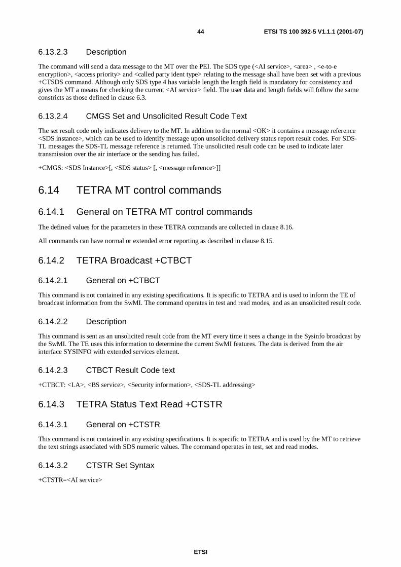
ETSI
ETSI TS 100 392-5 V1.1.1 (2001-07)44
6.13.2.3 Description
The command will send a data message to the MT over the PEI. The SDS type (<AI service>, <area> , <e-to-eencryption>, <access priority> and <called party ident type> relating to the message shall have been set with a previous+CTSDS command. Although only SDS type 4 has variable length the length field is mandatory for consistency andgives the MT a means for checking the current <AI service> field. The user data and length fields will follow the sameconstricts as those defined in clause 6.3.
6.13.2.4 CMGS Set and Unsolicited Result Code Text
The set result code only indicates delivery to the MT. In addition to the normal <OK> it contains a message reference<SDS instance>, which can be used to identify message upon unsolicited delivery status report result codes. For SDS-TL messages the SDS-TL message reference is returned. The unsolicited result code can be used to indicate latertransmission over the air interface or the sending has failed.
+CMGS: <SDS Instance>[, <SDS status> [, <message reference>]]
6.14 TETRA MT control commands
6.14.1 General on TETRA MT control commands
The defined values for the parameters in these TETRA commands are collected in clause 8.16.
All commands can have normal or extended error reporting as described in clause 8.15.
6.14.2 TETRA Broadcast +CTBCT
6.14.2.1 General on +CTBCT
This command is not contained in any existing specifications. It is specific to TETRA and is used to inform the TE ofbroadcast information from the SwMI. The command operates in test and read modes, and as an unsolicited result code.
6.14.2.2 Description
This command is sent as an unsolicited result code from the MT every time it sees a change in the Sysinfo broadcast bythe SwMI. The TE uses this information to determine the current SwMI features. The data is derived from the airinterface SYSINFO with extended services element.
6.14.2.3 CTBCT Result Code text
+CTBCT: <LA>, <BS service>, <Security information>, <SDS-TL addressing>
6.14.3 TETRA Status Text Read +CTSTR
6.14.3.1 General on +CTSTR
This command is not contained in any existing specifications. It is specific to TETRA and is used by the MT to retrievethe text strings associated with SDS numeric values. The command operates in test, set and read modes.
6.14.3.2 CTSTR Set Syntax
+CTSTR=<AI service>

ETSI
ETSI TS 100 392-5 V1.1.1 (2001-07)45
6.14.3.3 Description
The TE uses this command to retrieve text strings stored in the MT memories. Status and SDS type 1 in particular havetext strings associate with them, which have meaning to a particular user or application. The TE would typically use thiscommand at link recovery. Then the text strings looked up by the TE when reading SDS messages would be used inpreference to the numeric value indicated in the <message index> field. Note the only valid values for <AI service> arethose where text strings are given (status and SDS1).
6.14.3.4 CTSTR Read Result Code text
+CTSTR: <AI service>, <Status (or SDS 1) value>, <text> <CR><LF>
<Status (or SDS 1) value>, <text> <CR><LF>6.14.4TETRA Service Profile +CTSP
6.14.4 Void
6.14.4.1 General on +CTSP
This command is not contained in any existing specifications. It is specific to TETRA and is used to inhibit incomingcall signalling (from the air interface) to be sent to the TE by the MT. The command operates in test, set and readmodes.
6.14.4.2 CTSP Set Syntax
+CTSP=<service profile>, <service layer1>[, <service layer2>] [, <PID>]
6.14.4.3 Description
This command is used to disable incoming call signalling (from the air interface) to the MT to be sent to the PEI. Thedefault is that all signalling is forwarded to the PEI so a TE should disable each service for which it does not want toaccept signalling. The read command will return all non-default services with a profile set by the TE.
NOTE 1: If the <service layer1> is SDS-TL then the <PID> field is valid instead of <service layer2>.
NOTE 2: The <service layer2> element need not be present if all of the <service layer1> services are to be routed.
NOTE 3: The "MM" service layers are different from the others as all air interface downlink messages are alwayssent to "both".
NOTE 4: If the <service layer1> is an SDS service and the MS has a message stack, then the profile only applies tothe routing of "new message in the stack" indications (CMTI).
NOTE 5: If the service is status, some reserved values for SDS-TL acknowledgements ([2] clause 14.8.34) will besent to both.
6.14.4.4 CTSP Read Result Code text
+CTSP: =<service profile>, <service layer1>[, <service layer2>] [, <PID>] <CR><LF>
<service profile>, <service layer1>[, <service layer2>] [, <PID>] <CR><LF>
6.14.5 TETRA service definition for Circuit Mode services +CTSDC
6.14.5.1 General on +CTSDC
This command is not contained in any existing specifications. It is specific to TETRA and is used in conjunction with(before) other commands to perform outgoing TETRA call set up (of any sort). The command and associated responsesshall be as presented below. The command operates in test, set and read modes.
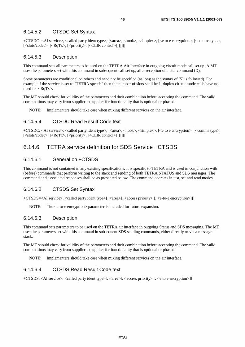
ETSI
ETSI TS 100 392-5 V1.1.1 (2001-07)46
6.14.5.2 CTSDC Set Syntax
+CTSDC=<AI service>, <called party ident type>, [<area>, <hook>, <simplex>, [<e to e encryption>, [<comms type>,[<slots/codec>, [<RqTx>, [<priority>, [<CLIR control>]]]]]]]
6.14.5.3 Description
This command sets all parameters to be used on the TETRA Air Interface in outgoing circuit mode call set up. A MTuses the parameters set with this command in subsequent call set up, after reception of a dial command (D).
Some parameters are conditional on others and need not be specified (as long as the syntax of [5] is followed). Forexample if the service is set to "TETRA speech" then the number of slots shall be 1, duplex circuit mode calls have noneed for <RqTx>.
The MT should check for validity of the parameters and their combination before accepting the command. The validcombinations may vary from supplier to supplier for functionality that is optional or phased.
NOTE: Implementers should take care when mixing different services on the air interface.
6.14.5.4 CTSDC Read Result Code text
+CTSDC: <AI service>, <called party ident type>, [<area>, <hook>, <simplex>, [<e to e encryption>, [<comms type>,[<slots/codec>, [<RqTx>, [<priority>, [<CLIR control>]]]]]]]
6.14.6 TETRA service definition for SDS Service +CTSDS
6.14.6.1 General on +CTSDS
This command is not contained in any existing specifications. It is specific to TETRA and is used in conjunction with(before) commands that perform writing to the stack and sending of both TETRA STATUS and SDS messages. Thecommand and associated responses shall be as presented below. The command operates in test, set and read modes.
6.14.6.2 CTSDS Set Syntax
+CTSDS=<AI service>, <called party ident type>[, <area>[, <access priority> [, <e-to-e encryption>]]]
NOTE: The <e-to-e encryption> parameter is included for future expansion.
6.14.6.3 Description
This command sets parameters to be used on the TETRA air interface in outgoing Status and SDS messaging. The MTuses the parameters set with this command in subsequent SDS sending commands, either directly or via a messagestack.
The MT should check for validity of the parameters and their combination before accepting the command. The validcombinations may vary from supplier to supplier for functionality that is optional or phased.
NOTE: Implementers should take care when mixing different services on the air interface.
6.14.6.4 CTSDS Read Result Code text
+CTSDS: <AI service>, <called party ident type>[, <area>[, <access priority> [, <e to e encryption>]]]

ETSI
ETSI TS 100 392-5 V1.1.1 (2001-07)47
6.15 New TETRA call handling commands
6.15.1 General on new TETRA call handling commands
This clause deals with call handling of TETRA circuit mode (voice or data) calls and incoming SDS messages that arenot sent to the message stack. New outgoing circuit mode call set up commands are used in conjunction with the servicedefinition command +CTSDC. The two commands are used in sequence to set the behaviour of the MT and to initiate acall.
The defined values for the parameters in these TETRA commands are collected in clause 8.16.
All commands can have normal or extended error reporting as described in clause 8.15.
6.15.2 TETRA Call Connect +CTCC
6.15.2.1 General on +CTCC
This command is not contained in any existing specifications. It is specific to TETRA and is used to inform the MT thata call set up phase has finished and the call maintenance phase should be entered. The command operates in test and setmodes.
6.15.2.2 CTCC Set Syntax
+CTCC=<CC Instance>, <hook>, <simplex>, [<AI service>, [<e to e encryption>, [<comms type>, [<slots/codec>,[<proprietary>]]]]]]]
6.15.2.3 Description
This command is used to end the call set up phase for incoming and outgoing calls to the MT. It contains all theparameters necessary to connect the called and calling parties. For half duplex calls this will include the transmissiongrant state. This command may be used to modify parameters of the call set up request.
6.15.3 TETRA Call Release +CTCR
6.15.3.1 General on +CTCR
This is an unsolicited response code and is not contained in any existing specifications.
6.15.3.2 Description
This response is specific to TETRA and is based on the D-Release message. It indicates to the TE that either the otherparty or the network has cleared an ongoing call.
6.15.3.3 CTCR Unsolicited Result Code Text
+CTCR: <CC instance >, <disconnect cause>

ETSI
ETSI TS 100 392-5 V1.1.1 (2001-07)48
6.15.4 TETRA Incoming Call Notification +CTICN
6.15.4.1 General on +CTICN
This is an unsolicited response code and is not contained in any existing specifications.
6.15.4.2 Description
This unsolicited response is specific to TETRA and is based on the TETRA D-Set-up, D-Connect Ack and D-Infomessages. It indicates an incoming call and its progress to the TE. The TE uses the parameters set with this command tointerpret how to handle the call (e.g. whether to sound a ringing tone (hook) or to start call maintenance (direct) orpossibly to negotiate slot use according to the baud rate on the PEI).
Some parameters are conditional on others. For example if the service is set to "TETRA speech" then the number ofslots shall be 1.
The fields <calling party ident type> and <ident> will normally be present in the first notification messages unless thecalling party has withheld them.
6.15.4.3 CTICN Unsolicited Result Code Text
+CTICN: <CC instance >, <call status>, <AI service>, [, <calling party ident type> [, <ident> [, <hook> [, <simplex> [,<e to e encryption> [<comms type>, [, <slots/codec>]]]]]]
6.15.5 TETRA outgoing Call progress notification +CTOCP
6.15.5.1 General on +CTOCP
This is an unsolicited response code and is not contained in any existing specifications.
6.15.5.2 Description
This response gives an indication to the TE as to the progress of an outgoing call. It is specific to TETRA and is basedon the Call-Proceeding, D-Alert, D-Connect and D-Info messages. The reception by the MT of one of these air interfacemessages will result in this PEI message. All parameters are subject to change by the SwMI in the course of a call set upso the TE should check their values even though it set them in the CTSDC command.
6.15.5.3 CTOCP Unsolicited Result Code Text
+CTOCP: <CC instance >, <call status>, <AI service>, [<hook> [, <simplex> [, <e to e encryption> [, <comms type> [,<slots/codec>]]]]
6.15.6 TETRA Group Set up +CTGS
6.15.6.1 General on +CTGS
This command is not contained in any existing specifications. The command should always supply the complete groupselection and scanning requirements; that is there is no history to a sequence of commands.
The command operates in test, set and read modes.
6.15.6.2 CTGS Set Syntax
+CTGS=<group type>, <Called Party Called Party Identity> … [, <group type>, < Called Party Identity>]

ETSI
ETSI TS 100 392-5 V1.1.1 (2001-07)49
6.15.6.3 Description
This command is used to instruct the MT to set groups in the MT as selected or scanned. The set result codes will begiven after all Air Interface signalling has been successfully completed.
If there is more than one group in the MT each group identity will be returned on a different line.
The result code can be unsolicited as the group attachments of the MT may change as it moves.
Note the variable "Called Party Identity" is used but it shall be a group identity obtained via the +CNUM command. Ifnot the set command should be rejected.
6.15.6.4 CTGS Read and unsolicited Result Code text
+CTGS: <group type>, < Called Party Identity><CR><LF>
… [, <group type>, < Called Party Identity>]
6.15.7 TETRA SDS Receive +CTSDSR
6.15.7.1 General on +CTSDSR
This command is not contained in any existing specifications. It is specific to TETRA.
The command operates in test and read modes.
6.15.7.2 Description
This is an unsolicited message that carries an incoming SDS message from a MT that has no message stack.
6.15.7.3 CTSDSR unsolicited Result Codes
+CTSDSR: <AI service>, [<calling party ident>], [<calling party ident type>], <called party ident>, <called party identtype>, <length><CR><LF> user data.
6.15.8 Transmit Demand +CTXD
6.15.8.1 General on +CTXD
This command is not contained in any existing specifications.
The command operates in test and set modes.
6.15.8.2 CTXD Set Syntax
+CTXD= <CC instance >, <TxDemandPriority>[, <e to e encryption>]
6.15.8.3 Description
This command is specific to TETRA and is based on the U-TX Demand message. In a simplex call this command isused in conjunction with the transmission grant response to control the transmissions of the MT. The TE will generatethis command on pressing of the MMI representing the PTT. The only allowed result code is either <OK> or <error>.
6.15.9 Up Transmit Ceased +CUTXC
6.15.9.1 General +CUTXC
This command is not contained in any existing specifications.

ETSI
ETSI TS 100 392-5 V1.1.1 (2001-07)50
The command operates in test and set modes.
6.15.9.2 CUTXC Set Syntax
+CTXC= <CC instance >.
6.15.9.3 Description
This command is specific to TETRA and is based on the U-TxCeased message. In a simplex call this command is usedin conjunction with the transmission grant response to control the transmissions. The TE will generate this command onrelease of the MMI representing the PTT. The only allowed result code is either <OK> or <error>.
6.15.10 Transmission Grant +CTXG
6.15.10.1 General on +CTXG
This is an unsolicited response and is not contained in any existing specifications.
6.15.10.2 Description
This response is specific to TETRA and is based on the D-TxGrant message. It indicates to the TE who is allowed totransmit in a simplex call. Typically the TE may use this information to display the identity of the transmitting party.
6.15.10.3 CTXG Unsolicited Result Code Text
+CTXG: <CC instance >, <TxGrant>, <TxRqPrmsn>, <e to e encryption> [, <TPI type> [, <TPI>]]
6.15.11 Down Transmission Ceased +CDTXC
6.15.11.1 General on +CDTXC
This is an unsolicited response and is not contained in any existing specifications.
6.15.11.2 Description
This response is specific to TETRA and is based on the D-TxCeased message. In simplex calls it indicates to the TEthat the talking party has ceased its transmission so it can update its MMI. The TE may request permission to transmitdepending on the value of <TxRqPrmsn>.
6.15.11.3 CDTXC Unsolicited Result Code Text
+CTXG: <CC instance >, < TxRqPrmsn >
6.15.12 Transmission Continue +CTXN
6.15.12.1 General on +CTXN
This is an unsolicited response and is not contained in any existing specifications.
6.15.12.2 Description
This response is specific to TETRA and is based on the D-TX Continue message. In simplex calls it indicates to the TEthat an interrupted speech item may continue. The TE may request permission to transmit depending on the value of<TxRqPrmsn>.
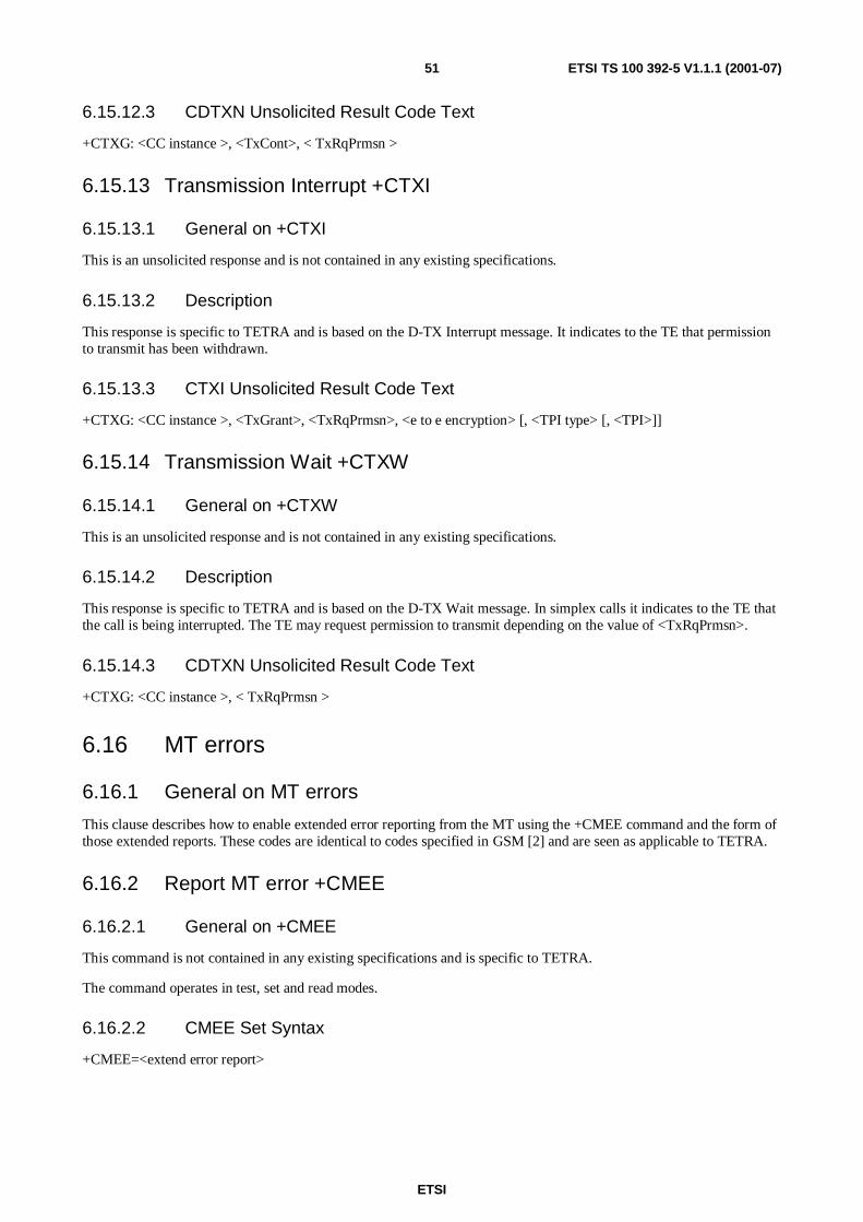
ETSI
ETSI TS 100 392-5 V1.1.1 (2001-07)51
6.15.12.3 CDTXN Unsolicited Result Code Text
+CTXG: <CC instance >, <TxCont>, < TxRqPrmsn >
6.15.13 Transmission Interrupt +CTXI
6.15.13.1 General on +CTXI
This is an unsolicited response and is not contained in any existing specifications.
6.15.13.2 Description
This response is specific to TETRA and is based on the D-TX Interrupt message. It indicates to the TE that permissionto transmit has been withdrawn.
6.15.13.3 CTXI Unsolicited Result Code Text
+CTXG: <CC instance >, <TxGrant>, <TxRqPrmsn>, <e to e encryption> [, <TPI type> [, <TPI>]]
6.15.14 Transmission Wait +CTXW
6.15.14.1 General on +CTXW
This is an unsolicited response and is not contained in any existing specifications.
6.15.14.2 Description
This response is specific to TETRA and is based on the D-TX Wait message. In simplex calls it indicates to the TE thatthe call is being interrupted. The TE may request permission to transmit depending on the value of <TxRqPrmsn>.
6.15.14.3 CDTXN Unsolicited Result Code Text
+CTXG: <CC instance >, < TxRqPrmsn >
6.16 MT errors
6.16.1 General on MT errors
This clause describes how to enable extended error reporting from the MT using the +CMEE command and the form ofthose extended reports. These codes are identical to codes specified in GSM [2] and are seen as applicable to TETRA.
6.16.2 Report MT error +CMEE
6.16.2.1 General on +CMEE
This command is not contained in any existing specifications and is specific to TETRA.
The command operates in test, set and read modes.
6.16.2.2 CMEE Set Syntax
+CMEE=<extend error report>
ETSI
ETSI TS 100 392-5 V1.1.1 (2001-07)52
6.16.2.3 Description
Set command disables or enables the use of the final result code +CME ERROR: <extended error report code>. Whenenabled, MT related errors cause +CME ERROR: <extended error report code> instead of the regular ERROR finalresult code. ERROR is returned when the error is related to syntax, invalid parameters or MT functionality.
6.16.2.4 CMEE Set Result Code Text
+CMEE: <extend error report>
6.16.3 MT error result code +CME ERROR
6.16.3.1 General on +CME ERROR
This command is not contained in any existing specifications and is specific to TETRA.
The command operates in test and unsolicited result modes.
6.16.3.2 Description
The response +CME ERROR: <extended error report code> result code is similar to the regular ERROR result code butgives the TE more detailed information on the command error.
The format of <extended error report code> can be either numeric or verbose. This is set with the command +CMEE.
NOTE: ITU-T Recommendation V.250 [5] command V does not affect the format of this result code.
6.16.3.3 CME ERROR Unsolicited Result Code Text
+CME ERROR <extended error report code>
6.17 Parameter description and values
6.17.1 General on parameters
This clause details the allowed values for the parameters used in the commands specific to TETRA. The valueparameters shall be encoded in decimal digits using the default character set unless changed by the CSCS command.
The values are presented in both numeric and verbose formats where applicable.
The default values are underlined.
The MT should check combinations of parameters in command lines to ensure they are compatible with TETRAoperation.
6.17.2 Access Priority
The lower layers of the MT use this to give PDUs a priority for access to the air interface.
- 0 - Low;
- 1 - High;
- 2 - Emergency.
6.17.3 AI Service
This parameter is used to determine the type of service to be used in air interface call set up signalling. The services areall defined in EN 300 392-2 [2].
ETSI
ETSI TS 100 392-5 V1.1.1 (2001-07)53
• 0 - TETRA speech;
• 1 - 7,2 kbit/s unprotected data;
• 2 - Low protection 4,8 kbit/s short interleaving depth = 1;
• 3 - Low protection 4,8 kbit/s medium interleaving depth = 4;
• 4 - Low protection 4,8 kbit/s long interleaving depth = 8;
• 5 - High protection 2,4 kbit/s short interleaving depth = 1;
• 6 - High protection 2,4 kbit/s medium interleaving depth = 4;
• 7 - High protection 2,4 kbit/s high interleaving depth = 8;
• 8 - Packet Data;
• 9 - SDS type 1 (16 bits);
• 10 - SDS type 2 (32 bits);
• 11 - SDS type 3 (64 bits);
• 12 - SDS type 4 (0 - 2 047 bits);
• 13 - Status (16 bits, some values are reserved in EN 300 392-2 [2]).
6.17.4 Alpha
Optional alphanumeric string used to help MMI for TETRA identities returned with the CNUM command.
6.17.5 Area
Area [2] used by the area selection supplementary service in call set up.
NOTE: Some SwMIs use this field without the SS to restrict group call area during the set up phase. The areas arepredefined in the SwMI and are made up of Location Areas.
• 0 - Area not defined;
• 1 - Area 1;
• 2 - Area 2;
• 3 - Area 3;
• 4 - Area 4;
• 5 - Area 5;
• 6 - Area 6;
• 7 - Area 7;
• 8 - Area 8;
• 9 - Area 9;
• 10 - Area 10;
• 11 - Area 11;
• 12 - Area 12;

ETSI
ETSI TS 100 392-5 V1.1.1 (2001-07)54
• 13 - Area 13;
• 14 - Area 14;
• 15 - All areas.
6.17.6 BS service
This parameter is used to indicate to the TE, the supported services of the BS where the MT is registered. The table iscopied into table 12, from EN 300 392-2 [2] for convenience. The table in EN 300 392-2 [2] will always takeprecedence. The table gives a bit oriented indication of the MS capabilities. The value sent in the command line stringwill be the HEX equivalent of the total bit array, with the MSB the one at the top of the table. For example a BS capableof all services will have the parameter value "FFF".
Table 12: +BS Service Details
Information element Length Value RemarkRegistration 1 0 Registration not required on this cell
1 Registration mandatory on this cellDe-registration 1 0 De-registration not required on this cell
1 De-registration mandatory on this cellPriority cell 1 0 Cell is not a priority cell
1 Cell is a priority cellMinimum mode service 1 0 Cell may use minimum mode
1 Cell never uses minimum modeMigration 1 0 Migration is not supported by this cell
1 Migration is supported by this cellSystem wide services 1 0 System wide services temporarily not supported
1 Normal modeTETRA voice service 1 0 TETRA voice service is not supported on this cell
1 TETRA voice service is supported on this cellCircuit mode data service 1 0 Circuit mode data service is not supported on this cell
1 Circuit mode data service is supported on this cellReserved 1 0 Service is not available on this cell
1 Service is available on this cellSNDCP Service 1 0 SNDCP service is not available on this cell
1 SNDCP service is available on this cellAir interface encryption 1 0 Air interface encryption is not available on this cellService 1 Air interface encryption is available on this cellAdvanced link supported 1 0 Advanced link is not supported on this cell
1 Advanced link is supported on this cell
6.17.7 Call status
This parameter is used to indicate the status of either incoming or outgoing circuit mode call set up. The values are sentin D-Call Proceeding and D-info on the air interface.
• 0 - Call progressing;
• 1 - Call queued;
• 2 - Called party paged;
• 3 - Call continue;
• 4 - Hang time expired.
6.17.8 Called party identity
A digit stream to be interpreted dependant on the value of <called party type>. The presentation shall be in ASCII. Ifthe called party type is an external subscriber number then the gateway identity is provisioned in the MT.

ETSI
ETSI TS 100 392-5 V1.1.1 (2001-07)55
6.17.9 Calling party identity
A digit stream to be interpreted dependant on <calling party type>. The presentation shall be in ASCII.
Typically used by any TE MMI to display the identity of the calling party.
6.17.10 Called party identity type
This parameter is used to indicate the type of identity to be used as the called party address. The associated identity usedin signalling will be interpreted differently according to this parameter. External subscriber number addresses are usedin association with a PSTN or PABX gateway.
• 0 - SSI;
• 1 - TSI;
• 2 - SNA;
• 3 - PABX external subscriber number;
• 4 - E164 external subscriber number.
NOTE: The actual value of the gateway identities (PSTN, PABX) is provisioned in the MT and cannot bechanged over the PEI by AT commands. The rules governing what the "leading digit" in a diallingscheme means are also defined in the MT. For example there may be more than one PABX gateway thatcan be chosen using this digit. The leading digit may be discarded before dialling.
6.17.11 Calling party identity type
This parameter is used to indicate the type of identity received as the calling party address. The associated identity usedin signalling will be interpreted differently according to this parameter. External subscriber number addresses are usedin association with a PSTN or PABX gateway.
• 0 - SSI;
• 1 - TSI;
• 2 - Reserved;
• 3 - PABX external subscriber number;
• 4 - PSTN external subscriber number.
6.17.12 CC instance
A three-digit number used to identify an ongoing call. The originating MT assigns it. The number will be assigned atthe beginning of any particular call (incoming or outgoing) and used to relate all PEI signalling related to that call. Thevalue of CC instance is not used on the air interface, although there is an equivalent "call identity".
6.17.13 Class of MS
This parameter is used to indicate to the TE the capabilities of the MS regarding air interface characteristics. The tableis copied, into table 13 from EN 300 392-2 [2] for convenience. The table in EN 300 392-2 [2] will always takeprecedence. The table gives a bit oriented indication of the MS capabilities. The value sent in the command line stringwill be the HEX equivalent of the total bit array, with the MSB the one at the top of the table. For example a MScapable of all services except security will have the parameter value "FFFF00".
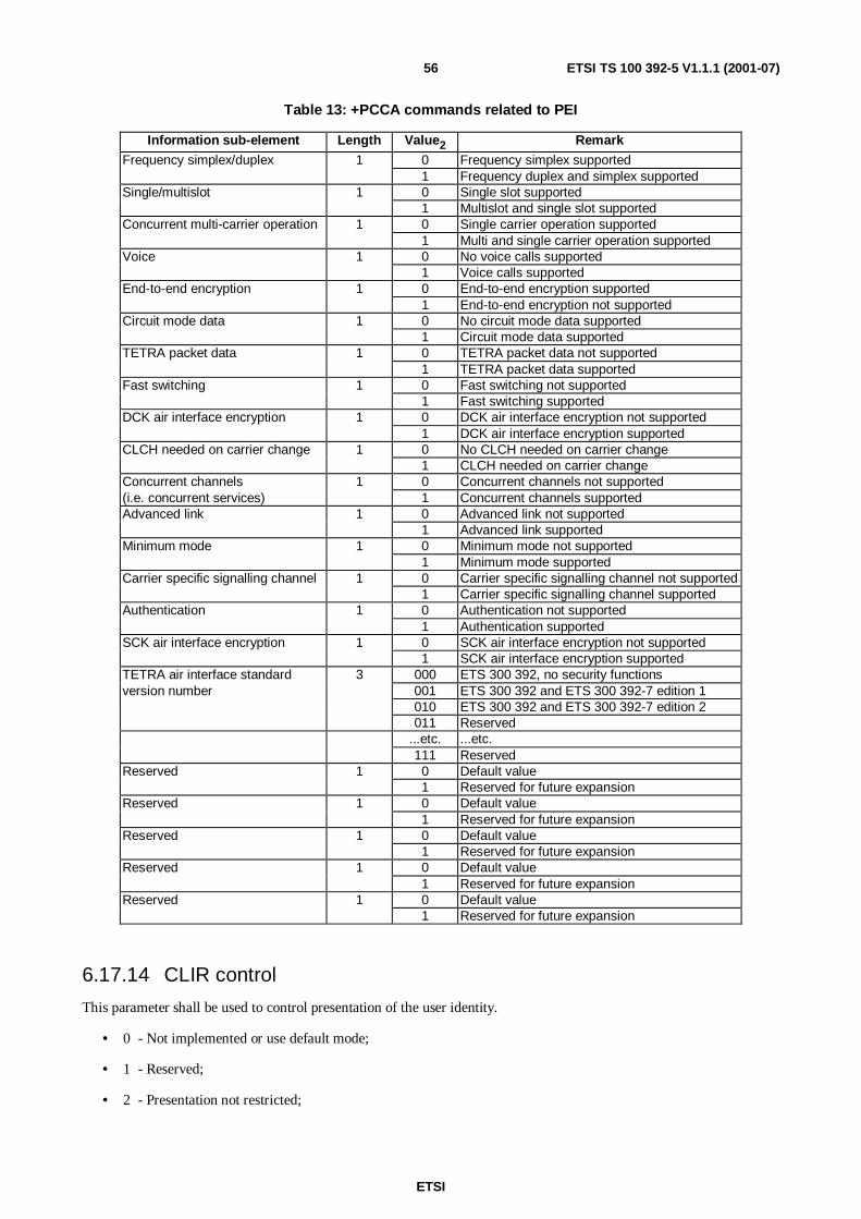
ETSI
ETSI TS 100 392-5 V1.1.1 (2001-07)56
Table 13: +PCCA commands related to PEI
Information sub-element Length Value2 Remark
Frequency simplex/duplex 1 0 Frequency simplex supported1 Frequency duplex and simplex supported
Single/multislot 1 0 Single slot supported1 Multislot and single slot supported
Concurrent multi-carrier operation 1 0 Single carrier operation supported1 Multi and single carrier operation supported
Voice 1 0 No voice calls supported1 Voice calls supported
End-to-end encryption 1 0 End-to-end encryption supported1 End-to-end encryption not supported
Circuit mode data 1 0 No circuit mode data supported1 Circuit mode data supported
TETRA packet data 1 0 TETRA packet data not supported1 TETRA packet data supported
Fast switching 1 0 Fast switching not supported1 Fast switching supported
DCK air interface encryption 1 0 DCK air interface encryption not supported1 DCK air interface encryption supported
CLCH needed on carrier change 1 0 No CLCH needed on carrier change1 CLCH needed on carrier change
Concurrent channels 1 0 Concurrent channels not supported(i.e. concurrent services) 1 Concurrent channels supportedAdvanced link 1 0 Advanced link not supported
1 Advanced link supportedMinimum mode 1 0 Minimum mode not supported
1 Minimum mode supportedCarrier specific signalling channel 1 0 Carrier specific signalling channel not supported
1 Carrier specific signalling channel supportedAuthentication 1 0 Authentication not supported
1 Authentication supportedSCK air interface encryption 1 0 SCK air interface encryption not supported
1 SCK air interface encryption supportedTETRA air interface standard 3 000 ETS 300 392, no security functionsversion number 001 ETS 300 392 and ETS 300 392-7 edition 1
010 ETS 300 392 and ETS 300 392-7 edition 2011 Reserved
...etc. ...etc.111 Reserved
Reserved 1 0 Default value1 Reserved for future expansion
Reserved 1 0 Default value1 Reserved for future expansion
Reserved 1 0 Default value1 Reserved for future expansion
Reserved 1 0 Default value1 Reserved for future expansion
Reserved 1 0 Default value1 Reserved for future expansion
6.17.14 CLIR control
This parameter shall be used to control presentation of the user identity.
• 0 - Not implemented or use default mode;
• 1 - Reserved;
• 2 - Presentation not restricted;

ETSI
ETSI TS 100 392-5 V1.1.1 (2001-07)57
• 3 - Presentation restricted.
6.17.15 Comms type
This parameter is used to indicate the type of communication to be used in the maintenance phase of the current callset up.
• 0 - Point to Point;
• 1 - Point to multipoint;
• 2 - Point to multipoint (acknowledged);
• 3 - Broadcast.
6.17.16 Disconnect cause
This parameter is given in the disconnect message from the MT when a voice call is cleared by the other end, the SwMIor the MT itself. The TE could use the information in MMI or to initiate retries.
• 0 - Not defined or unknown;
• 1 - User request;
• 2 - Called party busy;
• 3 - Called party not reachable;
• 4 - Called party does not support encryption;
• 5 - Network congestion;
• 6 - Not allowed traffic;
• 7 - Incompatible traffic;
• 8 - Service not available;
• 9 - Pre-emption;
• 10 - Invalid call identifier;
• 11 - Called party rejection;
• 12 - No CC entity;
• 13 - Timer expiry;
• 14 - SwMI disconnect;
• 15 - No acknowledgement;
• 16 - Unknown TETRA identity;
• 17 - Sublementary Service dependent;
• 18 - Unknown external subscriber number;
• 19 - Call restoration failed.

ETSI
ETSI TS 100 392-5 V1.1.1 (2001-07)58
6.17.17 E to E encryption
This parameter is used to indicate encryption is to be used in either incoming or outgoing circuit mode call set up.
• 0 - Clear;
• 1 - Encrypted.
NOTE: The encryption referred to is end to end, not air interface.
6.17.18 Extended error report
• 0 - Disable +CME ERROR: <extended error report code> and use "ERROR";
• 1 - Enable +CME ERROR: <extended error report code> result code and use numeric <extended error reportcode> values;
• 2 - Enable +CME ERROR: <extended error report code> result code and use verbose <extended error reportcode> values.
6.17.19 Extended error report codes
These are values returned as final result codes if extended error reporting is enabled and an error is encountered.
• 0 - MT failure;
• 1 - No connection to MT;
• 2 - MT adapter link reserved;
• 3 - Operations not allowed;
• 4 - Operation not supported;
• 5 - PH-SIM PIN required;
• 6 - Reserved;
• 7 - Reserved;
• 8 - Reserved;
• 9 - Reserved;
• 10 - SIM not inserted;
• 11 - SIM CHV1 required;
• 12 - SIM UNBLOCKING CHV1 required;
• 13 - SIM failure;
• 14 - SIM busy;
• 15 - SIM wrong;
• 16 - Incorrect password;
• 17 - SIM CHV2 required;
• 18 - SIM UNBLOCKING CHV2 required;
• 19 - Memory full;
ETSI
ETSI TS 100 392-5 V1.1.1 (2001-07)59
• 20 - Invalid index;
• 21 - Not found;
• 22 - Memory failure;
• 23 - Reserved;
• 24 - Text string too long;
• 25 - Invalid characters in text string;
• 26 - Dial string too long;
• 27 - Invalid characters in dial string;
• 28 - Reserved;
• 29 - Reserved;
• 30 - No network service;
• 31 - Network timeout;
• 32 - Error decoding data;
• 33 - Parameter wrong type;
• 34 - Parameter value out of range;
• 35 - Syntax error;
• 36 - Data received without command;
• 37 - Timeout waiting for data;
• 38 - Protocol identifier already registered;
• 39 - Registration table full;
• 100 - Unknown;
• 101 - 150 Reserved for use by GPRS (values are specified in GSM 07.60 [27]);
• 151 - 255 Reserved;
• 330 - SMSC address unknown;
6.17.20 Group type
This parameter is used when setting the MT groups for use. A selected group will be used for outgoing calls. Eitherselected or scanned groups will receive incoming calls. Only incoming group calls with a priority higher than the scanlevel will interrupt ongoing group calls of a lower level.
If the group type is "none" all groups will be detached from the SwMI.
• 0 - None;
• 1 - Select;
• 2 - Scan priority 1;
• 3 - Scan priority 2;
• 4 - Scan priority 3;

ETSI
ETSI TS 100 392-5 V1.1.1 (2001-07)60
• 5 - Scan priority 4;
• 6 - Scan priority 5;
• 7 - Scan priority 6.
6.17.21 Hook
This parameter is used to indicate the type signalling in either incoming or outgoing circuit mode call set up. Anincoming hook signalling call should ring until answered by the TE. An incoming direct call will not ring but go straightto a circuit mode channel.
• 0 - Hook signalling;
• 1 - Direct.
6.17.22 LA
14-bit location area code [2] presented in character set defined by +CSCS.
NOTE: This field is only valid if the MT is registered (<Reg stat> = 1 or 5).
6.17.23 Length
This parameter indicates the length of the "user data" field in SDS related commands. The length is given in ASCIIdecimal. The length does not include the command line parameters used to delineate the user data (<CR>, <LF>, <Ctrl-Z> or <ESC> characters). In the event of optional parameters not present on the command line, the length parametercan be identified as the one before the <CR><LF> characters.
6.17.24 Message index
An identifier, for use with SDS message stack entries. This is independent of the memory location and is used inoperations on the message stack. There is a different message index for each of the two stacks, one for Status, SDS 1-3and one for SDS4. It has the range 0 - 65,535.
6.17.25 Message reference
An identifier used in the SDS-TL message protocol. For definition see [2] clause 29.
NOTE: The EN 300 812 [18] defines that the value "FF" is used when the message is waiting for transmissionand no real value is not yet allocated.
6.17.26 MNI
24 bits Mobile Network Identity [2] presented in character set defined by +CSCS.
NOTE: This field is only valid if the MT has roamed (<Reg stat> = 5).
6.17.27 Num type
This parameter is used to indicate the type of identity returned by the +CNUM command. The service centre is used as(an optional) part of the SDS-TL transport service protocol. The gateways returned are those used in the SwMI foraccess to PSTN and PABX services.
• 0 - Individual;
• 1 - Group;
• 2 - PSTN Gateway;
ETSI
ETSI TS 100 392-5 V1.1.1 (2001-07)61
• 3 - PABX Gateway;
• 4 - Service Centre (ITSI);
• 5 - Service Centre (E 164 number).
6.17.28 PID
This parameter is used in the capability and profile setting commands. It shall be used in conjunction with a "servicelayer1" of SDS-TL. Value taken for the PIDs are those defined in EN 300 392-2 [2] clause 29.
• 0 to 255.
6.17.29 Priority
This parameter is used to indicate the priority to be used in resource queueing of either incoming or outgoing circuitmode call set up. Refer to EN 300 392-12-10 [3] and ETS 300 392-12-16 [21] for further details.
• 0 - Priority not defined by this parameter;
• 1 - Priority 1;
• 2 - Priority 2;
• 3 - Priority 3;
• 4 - Priority 4;
• 5 - Priority 5;
• 6 - Priority 6;
• 7 - Priority 7;
• 8 - Priority 8;
• 9 - Priority 9;
• 10 - Priority 10;
• 11 - Priority 11;
• 12 - Priority 12;
• 13 - Priority 13;
• 14 - Priority 14;
• 15 - Priority 15.
6.17.30 Proprietary
This is a variable sized information element used to convey specific information relating to other fields in the currentcommand. It is included for possible future expansion of some commands.
NOTE: This element shall include the "proprietary element owner" element as the first field.
6.17.31 Proprietary element owner
This is the first part of the proprietary field to identify the manufacturer of the MT.
• 0 - Reserved;

ETSI
ETSI TS 100 392-5 V1.1.1 (2001-07)62
• 1 to 255 - Allocated to each manufacturer by ETSI (see annex H of EN 300 392-2 [2]).
6.17.32 Reg stat
This parameter is used to indicate the registration status of the MT to the TEI.
• 0 - Not registered or searching;
• 1 - Registered home network;
• 2 - Not registered, but MT is currently searching a network;
• 3 - System reject;
• 4 - Unknown;
• 5 - Registered, roaming.
6.17.33 Reg unsolic
This parameter enables the unsolicited reporting of changes in registration status and/or Location Area.
• 0 - disable network registration unsolicited result code;
• 1 - enable network registration unsolicited result code for change in registration status (Reg status) only;
• 2 - enable network registration unsolicited result code LA for change in registration status, MNI or LA.
6.17.34 RqTx
This parameter is used in outgoing simplex circuit mode calls to give the call originator the first speech/ data item.
• 0 - Request to Tx;
• 1 - No Request to Tx.
6.17.35 SDS instance
A two-digit number identifying a particular SDS message in sending of Status and SDS messages without using thestack. The originating MT assigns this number. The number will be assigned at the beginning of any particular messagesending and used to relate all PEI signalling related to that message sending. The value of SDS instance is not used onthe air interface.
6.17.36 SDS-TL addressing
This parameter is used to indicate the SwMI support for its preferred SDS-TL addressing method as described in theextended services broadcast. Refer to EN 300 392-2 [2] for further details.
• 0 - Reserved;
• 1 - Service centre addressing preferred;
• 2 - Never use service centre addressing;
• 3 - MS choice to use service centre addressing.
6.17.37 SDS Status
This parameter is used to indicate the status of outgoing and incoming SDS messages in the MT message stack. It isused to poll the stack for types of messages.

ETSI
ETSI TS 100 392-5 V1.1.1 (2001-07)63
• 0 - Incoming message stored and unread;
• 1 - Incoming message stored and read;
• 2 - Outgoing message stored and unsent;
• 3 - Outgoing message stored and sent.
6.17.38 Security information
An indication of whether the SwMI supports Air Interface encryption and if so what level. The full details can be foundin ETS 300 392-7 [19].
NOTE: Associated air interface Key information shall not be passed over the PEI. Class 1 systems have no AIencryption, class 2 systems use SCK AI encryption, and class 3 systems use authentication and AIencryption with both SCK and DCK.
• 0 - Class 1;
• 1 - Class 2;
• 2 - Class 3.
6.17.39 Service profile
This parameter is used to tell the MS where to route, or allow routing of air interface downlink and uplink signallingrespectively. Its main purposes are to prevent unnecessary signalling and to avoid conflict in responses.
• 0 - MT Only;
• 1 - TE Only;
• 2 - Both;
• 3 - Neither.
6.17.40 Service layer1
This parameter is used to indicate the MS capabilities and to set profiles directing services to and from the TE and/orMT. Each one is split into "layer2" sub-parameters.
• 0 - CC;
• 1 - MM;
• 2 - SDS;
• 3 - SDS-TL;
• 4 - Packet Data.
6.17.41 Service layer2
This parameter is used (in conjunction with "service layer1" to indicate the MS capabilities and to set profiles directingservices to and from the TE and/or MT. The set is split into groups of ten, where each group relates to a "layer1".
• 0 - Voice;
• 1 - Data;
• 2 - 9 Reserved;
• 10 - Registration;

ETSI
ETSI TS 100 392-5 V1.1.1 (2001-07)64
• 11 - Group Management;
• 12 - Security;
• 13 - Enable;
• 14 - Energy saving;
• 15 - 19 Reserved;
• 20 - Status;
• 21 - SDS type 1;
• 22 - SDS type 2;
• 23 - SDS type 3;
• 24 - SDS type 4 (not SDS-TL);
• 25 - 29 Reserved;
• 30 - IPV4;
• 31 - IPV6;
• 32 - 39 Reserved.
6.17.42 Simplex
This parameter is used to indicate the type of circuit mode channel in either an incoming or an outgoing call set up.Simplex channels will be used in conjunction with transmission request and grant signalling once the call is established(maintenance phase).
• 0 - Duplex;
• 1 - Simplex.
6.17.43 Slots/Codec
The meaning of this parameter is dependant on the value of <AI service> in the same command. If <AI service> is adata service then this field is used to indicate the number of air interface slots to be used in either incoming or outgoingpacket or circuit mode data call set up. If <AI service> is the voice service then this field indicates the type of Codecused.
Data
• 0 - 1 slot;
• 1 - 2 slots;
• 2 - 3 slots;
• 3 - 4 slots.
Speech
• 1 - TETRA encoded speech;
• 2 - Reserved;
• 3 - Reserved;
• 4 - Proprietary encoded speech.
ETSI
ETSI TS 100 392-5 V1.1.1 (2001-07)65
6.17.44 Stack full
This parameter is used to indicate when the MT message stack is full. TE applications should take care to ensure thestack does not stay full, as the MT can receive no more messages from the air interface. The application should deletemessages from the stack before any more arrive.
• 0 - Stack not full;
• 1 - Stack full.
6.17.45 Stack present
This parameter is used to indicate if the MT supports a SDS message stack.
• 0 - Stack present;
• 1 - Stack not present.
6.17.46 TPI (Transmitting Party Identity)
A digit stream to be interpreted dependant on <TPI type>. Typically used by the TE MMI to display the identity of theparty currently transmitting in a simplex call.
6.17.47 TPI (Transmitting Party Identity) type
This parameter is used in the call maintenance of a simplex call. It informs the TE how to interpret the TransmittingParty Identity field.
• 0 - SSI;
• 1 - TSI;
• 2 - External subscriber number.
NOTE: The SSI refers to the current network to which the MT is registered.
6.17.48 TxCont
This parameter is used in the call maintenance phase of simplex circuit mode calls. When received from the MT the TEwill know that any interruption of a call has ceased.
• 0 - Do not continue;
• 1 - Continue.
6.17.49 TxDemandPriority
This parameter is used in the call maintenance phase of simplex circuit mode calls. It sets the priority to be used in aparticular Tx Demand.
• 0 - Low;
• 1 - High;
• 2 - Pre-emptive;
• 3 - Emergency.
ETSI
ETSI TS 100 392-5 V1.1.1 (2001-07)66
6.17.50 TxGrant
This parameter is used in the call maintenance phase of simplex circuit mode calls. When received from the MT the TEwill know what to do with the transmitter on the established circuit.
• 0 - Transmission granted;
• 1 - Transmission not granted;
• 2 - Transmission queued;
• 3 - Transmission granted to another.
6.17.51 TxRqPrmsn
This parameter is used in the call maintenance phase of simplex circuit mode calls. It tells the TE whether it is allowedto request a transmission permission.
• 0 - Allowed to request;
• 1 - Not allowed to request.
6.17.52 User data
This is ASCII Hex representation of the user data bit stream in SDS related messages. Coding is done starting at the MSbit; each block of four bits is represented by one character; the characters are presented in the same order as the bitsthemselves (no swapping of nibbles). If the number of bits is not divisible by four, then the least significant bits of theleast significant Hex digit are packed with "0".
6.18 Outgoing call set up methodology
6.18.1 General on outgoing call set up methodology
This clause describes the procedures for successful set up of outgoing calls. In the event of an error at any step the MTwill reply with an error message and the call set up will be cancelled.
6.18.2 Voice calls
The initiation of an outgoing voice call takes two commands.
1) A +CTSDC command is used to set parameters for subsequent dial commands.
2) A D command is used to initiate a call set up using the predefined parameters.
Subsequent calls of the same type (e.g. group) do not need a new +CTSDC command but it is recommended that a newset of parameters be set for every call. Implementers should take care that no calls overlap if they have different CTSDCparameters.
The application within the TE may have different forms of MMI to generate these commands but these commands willalways be used to initiate an outgoing call. For example the MMI could have a PTT which when pushed would generatea set of signalling to initiate a group call.
The MT interprets the "D" command in different ways depending on the <AI service> and <called party ident type>parameters set by the +CTSDC command. The dialled string is normally used as the called party address and the call isset up using the parameters set by the previous +CTSDC command.
The MT should check the dialled string for valid numbering. Illegal numbers or combinations of the dialled string andthe +CTSDC parameters shall cause an error result code.

ETSI
ETSI TS 100 392-5 V1.1.1 (2001-07)67
A voice call is set up on an "ATD" command if the <AI service> parameter has been set to voice. The dialled string inthe "ATD" command will be treated in different ways depending on the values of <called party ident type>, <commstype> and <AI service>. When the final result code indicates successful execution of the "ATD" command the MT andTE still treat signalling on TD and RD as commands. This allows other services such as SDS and other voice calls torun concurrently, if the MT supports it.
1) If the <called party ident type> is PABX the MT will put the PABX gateway into the called party field on the airinterface and the dialled string into the ESN field.
2) If the <called party ident type> is PSTN the MT will put the PSTN gateway into the called party field on the airinterface and the dialled string into the ESN field.
3) In all other cases the MT will perform computations on the dialled string to generate the called party addressfield used on the air interface. The computations will depend on the value of <called party ident type>.
The outgoing call progress responses (+CTOP) inform the TE of the call set up progress. The use of call progresssignalling is implementation dependant, but for example will be used by the TE to indicate a resource queue.
The reception of a connect (+CTCC) message informs the TE to enter the call maintenance phase.
NOTE: In some cases the final result code may be "CONNECT". This special case shall be predetermined in boththe MS and TE. Such predetermination is outside the scope of the present document and for this reasonit's use is not recommended.
6.18.3 Circuit mode data calls
The initiation of an outgoing circuit mode data call takes two commands.
1) A +CTSDC command is used to set parameters for subsequent dial commands.
2) A D command is used to initiate a call set up using the predefined parameters.
Subsequent calls of the same type do not need a new +CTSDC command but it is recommended that a new set ofparameters be set for every call. Implementers should take care that no calls overlap if they have different CTSDCparameters.
The MT interprets the "D" command in different ways depending on the <AI service> and <called party ident type>parameters set by the +CTSDC command. The dialled string is normally used as the called party address and the call isset up using the parameters set by the previous +CTSDC command.
The MT should check the dialled string for valid numbering. Illegal numbers or combinations of the dialled string andthe +CTSDC parameters shall cause an error result code.
A circuit mode data call is set up on a "ATD" command if the <AI service> parameter has been set to one of the circuitmode data selections (values 1-7). The MT will generate the called party address field used on the air interface from thedialled string in the "ATD" command. The computations will depend on the value of <called party ident type>. NotePSTN and PABX are not valid <called party ident types>. When the final result code indicates successful execution ofthe "ATD" command the MT and TE change to AT circuit mode data state. Signalling on TD and RD is treated as dataand passed through the MT as a transparent stream.
The outgoing call progress responses (+CTOP) inform the TE of the call set up progress The use of call progresssignalling is implementation dependant, but for example will be used by the TE to indicate a resource queue.
The reception of a connect (+CTCC) message informs the TE to enter the call maintenance phase.
NOTE: In some cases the final result code may be "CONNECT". This special case shall be predetermined in boththe MS and TE. Such predetermination is outside the scope of the present document and for this reasonit's use is not recommended.
ETSI
ETSI TS 100 392-5 V1.1.1 (2001-07)68
6.18.4 Sending of SDS messages
6.18.4.1 General on sending of SDS messages
The initiation of an outgoing SDS message can be done in two ways, directly to the air interface, or via the stack. Ineither case sending a message takes two commands. The choice of which method to use for SDS sending is TE and MTimplementation dependant. If the MT does not have message stack capability then "direct" shall be used.
1) A +CTSDS command is used to set parameters for subsequent CMGW or CMGS commands.
2) A CMGW or CMGS command is used to send the message (stack or direct) using the predefined parameters.
Subsequent calls of the same type do not need a new +CTSDS command but it is recommended that a new set ofparameters be set for every call. Implementers should take care that no calls overlap if they have different CTSDSparameters.
6.18.4.2 Send via Stack
The CTSDS command is followed by a CMGW command, which writes the message to the stack. The response to thecommand informs the TE of a reference (message index) within the stack. The message is sent (later) on the airinterface using a CMSS command from the TE. The CMSS command does not use the current setting for "called partyident type" of the CTSDS command but that stored in the stack for that message index. The other parameters of theU-SDS Data air interface PDU will be made up from the current CTSDS command.
If the message was a SDS-TL with a PID indicating use of the TL protocol the response will contain the messagereference of the SDS-TL layer.
NOTE: SDS messages that have not been sent on the air interface can be deleted from this stack, effectivelycancelling the send request.
6.18.4.3 Direct Send
An SDS direct send is initiated by a "CMSG" command if the <AI service> parameter has been set to one of the validSDS selection (values 9 - 13). The MT will generate the called party address field used on the air interface from theaddress field in the "CMSG" command. The computations will depend on the value of <called party ident type>.
NOTE: PSTN and PABX are not valid <called party ident types> for SDS messages.
6.19 Incoming call set up methodology
6.19.1 General on incoming call set up methodology
This clause describes the procedures for successful incoming calls. In the event of an error at any step the MT or TEwill reply with an error message and the call set up will be cancelled.
Incoming calls are always indicated by unsolicited messages from the MT towards the TE. The type of message and itsparameters will tell the TE all details of the incoming call.
6.19.2 Voice calls
The unsolicited response (+CTICN) informs the TE that a voice call request has been made to the TE/MT station. Theparameters are used to determine further TE actions. For example the parameters <hook> and <simplex> values willdetermine whether the TE starts a ring tone or goes straight to the call maintenance phase and whether to use the PTT inspeech calls.
In the event of hook signalling the TE will send the standard command "A" when the TE MMI (or application) goes"off hook" to continue the call set up process.
The incoming call progress may be updated by further optional messages (+CTICN) to inform the TE of the call set upprogress and for example will be used by the TE to indicate a resource queue.

ETSI
ETSI TS 100 392-5 V1.1.1 (2001-07)69
In the event of a voice call with direct signalling the TE MMI will indicate open voice paths to selected speakers andmicrophones.
When the call is ready for completion the TE sends a connect message to the MT and both enter the call maintenancephase.
6.19.3 Circuit mode data calls
The unsolicited response (+CTICN) with the right parameters informs the TE that a circuit mode data call request hasbeen made to the TE/MT station. The parameters are used to determine further TE actions. For example the parameters<hook> and <slots/codec> values will determine whether the TE starts a ring tone or goes straight to the callmaintenance phase and whether it needs to change the baud rate of the PEI.
In the event of hook signalling the TE will send the standard command "A" when the TE MMI goes "off hook" tocontinue the call set up process.
The incoming call progress may be updated by further optional messages (+CTICN) to inform the TE of the call set upprogress and for example will be used by the TE to indicate a resource queue.
In the event of a circuit mode data call with direct signalling the TE MMI will indicate connection and connect the datadevice to the circuit.
When the call is ready for completion the TE sends a connect message to the MT and both will change state to ATcircuit mode data. Signalling on TD and RD will now be treated as data. Call maintenance is described in clause 8.1.8.
6.19.4 Reception of SDS messages
6.19.4.1 Received via Stack
The TE will receive the unsolicited message +CMTI to indicate a new message has been stored on the MT messagestack. The parameters of this message will inform the TE of the type of message and where it is to be found. A "list"and subsequent "read" message are used to retrieve the messages from the appropriate stack. SDS-TL messages willneed handling according to the SDS-TL protocol, including sending a "consumed" message back to the source.
Both TE and MT stay in the command state.
6.19.4.2 Direct Received
The TE will receive the unsolicited message +CTSDSR, which has all parameters to define the message type and itscontents. SDS-TL messages will need handling according to the SDS-TL protocol, including sending a "consumed"message back to the source.
6.20 Voice and circuit mode data call maintenance commandsIn the voice and circuit mode data call maintenance phase the treatment of signalling on circuits TD and RD will beused for in call signalling, including disconnect.
In voice calls, the <simplex> parameter will indicate to the TE whether or not to use the MMI and commandsassociated with PTT. The outgoing commands are "transmit demand" and "transmit ceased" (+CTXD, +CUTXC). Theassociated responses will be "transmission granted" and "transmission ceased" (+CTXG, +CDTXC). The TE will usethese for MMI purposes, including the display of the talking party identity.
In order to use these commands the TE and MT shall change into the AT command state (using hardware or escapesignalling) the Transmit arbitration commands can be used. Once the transmit direction has been established the TEshall send an ATO command which (when acknowledged) will put both back into AT circuit data mode.
ETSI
ETSI TS 100 392-5 V1.1.1 (2001-07)70
6.21 Call clear down commands
6.21.1 General on call clear down commands
All circuit mode (voice and data) calls and packet data sessions have a clear down phase. These are treated differentlydepending on the type of call that is in progress and which end clears the call.
6.21.2 TE Initiated clear
1) A voice call can be cleared from the TE, by sending the standard command "H".
2) A circuit mode data call can be cleared from the TE, in one of two ways depending on the setting of the "&D"command. If the "&D" command has been set to "2" (orderly clear down of call) the TE drops the DTR circuit.
- If the hardware is not present then the "&D" command has been set to "0" (ignore DTR). In this case the TEsends an escape character (set by S2) sequence with guard times (set by S12) on the TD line. The MT shallbe capable of decoding this sequence out of the transparent data stream.
6.21.3 Network and MT Initiated clear
All calls will be subject to clearing by a remote station, the SwMI or the MT itself. Definitions of the source of a clearare beyond the scope of the present document but include reasons such as the other party clearing the call, time outs andpre-emption. Different services will have different timeouts, some set in a MT and some in the SwMI. Examples arespeech item duration (different for different speech services), circuit mode data duration and packet data session timer.
The TE will receive signalling as though the MT cleared the call.
1) A voice call can be cleared from the MT, by sending the release command (+CTCR) with its associated"disconnect cause" to indicate why and where the call clear was originated.
2) A circuit mode data call can be cleared from the MT in one of two ways:
- if the circuit DCD is available and &C has been set to 1 the MT drops the DCD circuit;
- if the hardware is not present then the &C has been set to 0 (ignore DCD) the MT can send the special "NOCARRIER" sequence with guard times. The TE shall be capable of decoding this sequence out of thetransparent data stream.
7 TNP1 service description
7.1 Service primitives at the TNP1A-SAPTNP1-SERVICE ACCESS request/indication: These primitives shall be used to extend the access to CMCE and MMservices to the user applications located in TE2.
TNP1- SDS SERVICE PROFILE request/indication/response/confirm: These primitives shall be used by the userapplications located in` TE2 to specify the SDS 1/2/3 and Status service profile.
TNP1- CC SERVICE PROFILE request/indication/response/confirm: These primitives shall be used by the userapplications located in TE2 to specify the CC service profile.
TNP1- MM SERVICE PROFILE request/indication/response/confirm: These primitives shall be used by the userapplications located in TE2 to specify the MM service profile.
TNP1- SDS-TL SERVICE PROFILE request/indication/response/confirm: These primitives shall be used by theuser applications located in TE2 to specify the SDS-TL service profile.
TNP1-UNITDATA request/indication: These primitives shall be used to send and receive U-plane circuit modetraffic to/from TMD-SAP.

ETSI
ETSI TS 100 392-5 V1.1.1 (2001-07)71
TNP1-UNITDATA REPORT indication: This primitive shall be used deliver indications from U-plane circuit modetraffic.
7.2 Service primitives at the TNP1B-SAPTNP1- SDS-TL CAPABILITY request/indication/response/confirm: These primitives shall be used to query theessential SDS-TL capabilities of a MT2 by user applications located in a TE2.
TNP1- SERVICES CAPABILITY request/indication/response/confirm: These primitives shall be used to query theessential capabilities (out of the SDS-TL capabilities) of a MT2 by user applications located in a TE2.
TNP1-IDENTIFICATION request/indication/response/confirm: These primitives shall be used to query theessential identification data of a MT2 by user applications located in a TE2.
TNP1-STATE request/indication/response/confirm: These primitives shall be used to query basic information of theoperational state of a MT2 by user applications located in a TE2.
7.3 Service primitives at TNP1A-SAP and TNP1B-SAPTNP1-CLOSE request/indication: These primitives shall be used to close the communication between peer TNP1entities.
TNP1-OPEN request/indication: These primitives shall be used to close the communication between peer TNP1entities.
TNP1-REPORT indication: This primitive shall be used to inform the user application about abnormal conditionswithin TNP1.
7.4 Primitive descriptions
7.4.1 TNP1- Services CAPABILITY
TNP1-SERVICES CAPABILITY request: shall be used by a TE2 user application to request capability information.
TNP1-SERVICES CAPABILITY indication: shall indicate a capability information request to the MT2 applicationin charge of providing the capability information.
TNP1-SERVICES CAPABILITY response: shall be used to initiate the capability information delivery by the MT2application in charge of providing the capability information.
TNP1-SERVICES CAPABILITY confirm: shall be used to deliver the capability information to an MT2 application.
The parameters of the primitives shall be as defined in table 14.
Table 14: Parameters for the primitive TNP1- SERVICES CAPABILITY
Parameter Request Indication Response ConfirmCircuit mode and MS services - - M MSecurity - - M MSDS mode services - - M MPacket mode services - - M MReserved, note M MNOTE: The reserved field is 8 bits in length.
7.4.2 TNP1- SDS-TL CAPABILITY
TNP1-SDS-TL CAPABILITY request: shall be used by a TE2 user application to request capability information.
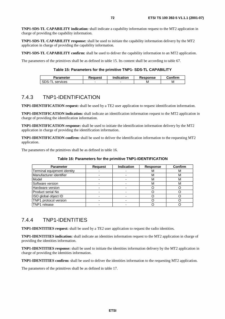
ETSI
ETSI TS 100 392-5 V1.1.1 (2001-07)72
TNP1-SDS-TL CAPABILITY indication: shall indicate a capability information request to the MT2 application incharge of providing the capability information.
TNP1-SDS-TL CAPABILITY response: shall be used to initiate the capability information delivery by the MT2application in charge of providing the capability information.
TNP1-SDS-TL CAPABILITY confirm: shall be used to deliver the capability information to an MT2 application.
The parameters of the primitives shall be as defined in table 15. Its content shall be according to table 67.
Table 15: Parameters for the primitive TNP1- SDS-TL CAPABILITY
Parameter Request Indication Response ConfirmSDS-TL services - - M M
7.4.3 TNP1-IDENTIFICATION
TNP1-IDENTIFICATION request: shall be used by a TE2 user application to request identification information.
TNP1-IDENTIFICATION indication: shall indicate an identification information request to the MT2 application incharge of providing the identification information.
TNP1-IDENTIFICATION response: shall be used to initiate the identification information delivery by the MT2application in charge of providing the identification information.
TNP1-IDENTIFICATION confirm: shall be used to deliver the identification information to the requesting MT2application.
The parameters of the primitives shall be as defined in table 16.
Table 16: Parameters for the primitive TNP1-IDENTIFICATION
Parameter Request Indication Response ConfirmTerminal equipment identity - - M MManufacturer identifier - - M MModel - - M MSoftware version - - M MHardware version - - O OProduct serial No - - O OISO global object ID - - O OTNP1 protocol version - - O OTNP1 release - - O O
7.4.4 TNP1-IDENTITIES
TNP1-IDENTITIES request: shall be used by a TE2 user application to request the radio identities.
TNP1-IDENTITIES indication: shall indicate an identities information request to the MT2 application in charge ofproviding the identities information.
TNP1-IDENTITIES response: shall be used to initiate the identities information delivery by the MT2 application incharge of providing the identities information.
TNP1-IDENTITIES confirm: shall be used to deliver the identities information to the requesting MT2 application.
The parameters of the primitives shall be as defined in table 17.
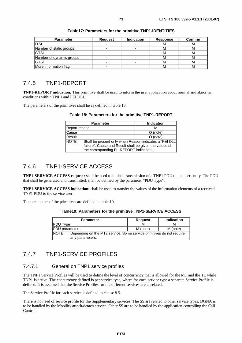
ETSI
ETSI TS 100 392-5 V1.1.1 (2001-07)73
Table17: Parameters for the primitive TNP1-IDENTITIES
Parameter Request Indication Response ConfirmITSI - - M MNumber of static groups - - M MGTSI - - M MNumber of dynamic groups - - M MGTSI - - M MMore information flag - M M
7.4.5 TNP1-REPORT
TNP1-REPORT indication: This primitive shall be used to inform the user application about normal and abnormalconditions within TNP1 and PEI DLL.
The parameters of the primitives shall be as defined in table 18.
Table 18: Parameters for the primitive TNP1-REPORT
Parameter IndicationReport reason MCause O (note)Result O (note)NOTE: Shall be present only when Reason indicates a "PEI DLL
failure". Cause and Result shall be given the values ofthe corresponding PL-REPORT indication.
7.4.6 TNP1-SERVICE ACCESS
TNP1-SERVICE ACCESS request: shall be used to initiate transmission of a TNP1 PDU to the peer entity. The PDUthat shall be generated and transmitted, shall be defined by the parameter "PDU Type".
TNP1-SERVICE ACCESS indication: shall be used to transfer the values of the information elements of a receivedTNP1 PDU to the service user.
The parameters of the primitives are defined in table 19.
Table19: Parameters for the primitive TNP1-SERVICE ACCESS
Parameter Request IndicationPDU Type M MPDU parameters M (note) M (note)NOTE: Depending on the MT2 service. Some service primitives do not require
any parameters.
7.4.7 TNP1-SERVICE PROFILES
7.4.7.1 General on TNP1 service profiles
The TNP1 Service Profiles will be used to define the level of concurrency that is allowed for the MT and the TE whileTNP1 is active. The concurrency defined is per service type, where for each service type a separate Service Profile isdefined. It is assumed that the Service Profiles for the different services are unrelated.
The Service Profile for each service is defined in clause 8.5.
There is no need of service profile for the Supplementary services. The SS are related to other service types. DGNA isto be handled by the Mobility attach/detach service. Other SS are to be handled by the application controlling the CallControl.
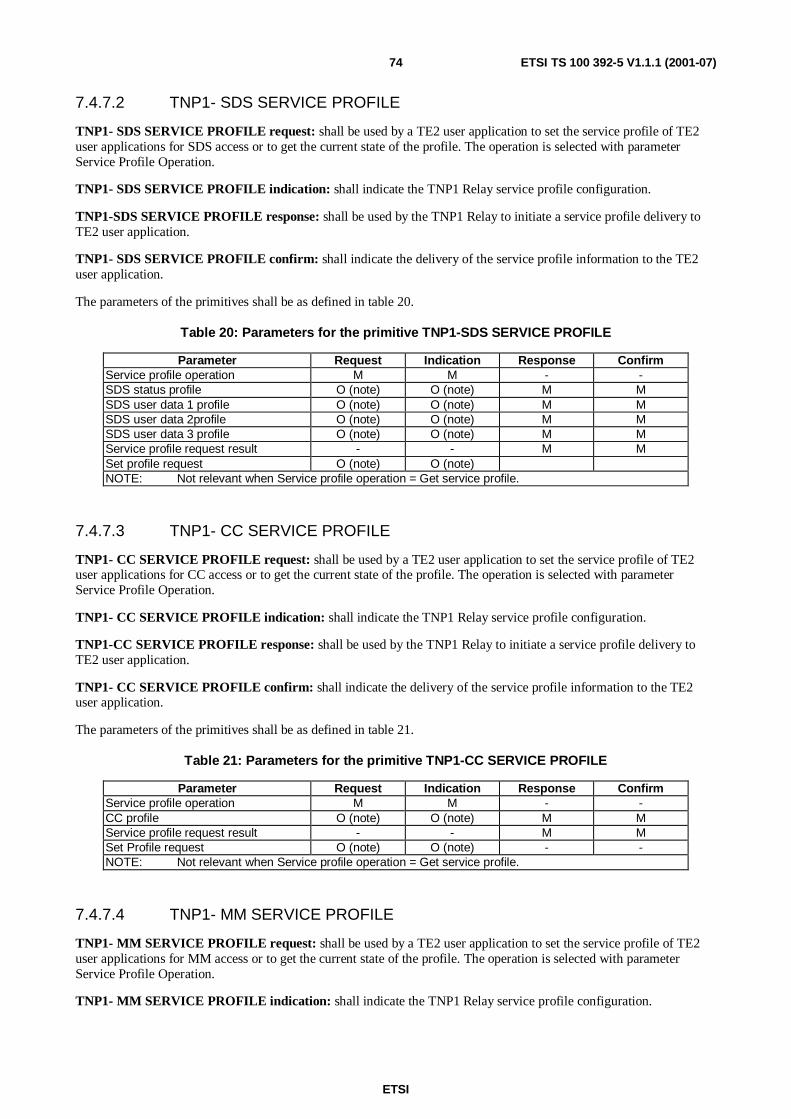
ETSI
ETSI TS 100 392-5 V1.1.1 (2001-07)74
7.4.7.2 TNP1- SDS SERVICE PROFILE
TNP1- SDS SERVICE PROFILE request: shall be used by a TE2 user application to set the service profile of TE2user applications for SDS access or to get the current state of the profile. The operation is selected with parameterService Profile Operation.
TNP1- SDS SERVICE PROFILE indication: shall indicate the TNP1 Relay service profile configuration.
TNP1-SDS SERVICE PROFILE response: shall be used by the TNP1 Relay to initiate a service profile delivery toTE2 user application.
TNP1- SDS SERVICE PROFILE confirm: shall indicate the delivery of the service profile information to the TE2user application.
The parameters of the primitives shall be as defined in table 20.
Table 20: Parameters for the primitive TNP1-SDS SERVICE PROFILE
Parameter Request Indication Response ConfirmService profile operation M M - -SDS status profile O (note) O (note) M MSDS user data 1 profile O (note) O (note) M MSDS user data 2profile O (note) O (note) M MSDS user data 3 profile O (note) O (note) M MService profile request result - - M MSet profile request O (note) O (note)NOTE: Not relevant when Service profile operation = Get service profile.
7.4.7.3 TNP1- CC SERVICE PROFILE
TNP1- CC SERVICE PROFILE request: shall be used by a TE2 user application to set the service profile of TE2user applications for CC access or to get the current state of the profile. The operation is selected with parameterService Profile Operation.
TNP1- CC SERVICE PROFILE indication: shall indicate the TNP1 Relay service profile configuration.
TNP1-CC SERVICE PROFILE response: shall be used by the TNP1 Relay to initiate a service profile delivery toTE2 user application.
TNP1- CC SERVICE PROFILE confirm: shall indicate the delivery of the service profile information to the TE2user application.
The parameters of the primitives shall be as defined in table 21.
Table 21: Parameters for the primitive TNP1-CC SERVICE PROFILE
Parameter Request Indication Response ConfirmService profile operation M M - -CC profile O (note) O (note) M MService profile request result - - M MSet Profile request O (note) O (note) - -NOTE: Not relevant when Service profile operation = Get service profile.
7.4.7.4 TNP1- MM SERVICE PROFILE
TNP1- MM SERVICE PROFILE request: shall be used by a TE2 user application to set the service profile of TE2user applications for MM access or to get the current state of the profile. The operation is selected with parameterService Profile Operation.
TNP1- MM SERVICE PROFILE indication: shall indicate the TNP1 Relay service profile configuration.

ETSI
ETSI TS 100 392-5 V1.1.1 (2001-07)75
TNP1-MM SERVICE PROFILE response: shall be used by the TNP1 Relay to initiate a service profile delivery toTE2 user application.
TNP1- MM SERVICE PROFILE confirm: shall indicate the delivery of the service profile information to the TE2user application.
The parameters of the primitives shall be as defined in table 22.
Table 22: Parameters for the primitive TNP1-MM SERVICE PROFILE
Parameter Request Indication Response ConfirmService profile operation M M - -MM profile O (note) O (note) M MService profile request result - - M MSet profile request O (note) O (note) - -NOTE: Not relevant when Service profile operation = Get service profile.
7.4.7.5 TNP1- SDS-TL SERVICE PROFILE
TNP1- SDS-TL SERVICE PROFILE request: shall be used by a TE2 user application to set the service profile ofTE2 user applications for SDS-TL access or to get the current state of the profile. The operation is selected withparameter Service Profile Operation.
TNP1- SDS-TL SERVICE PROFILE indication: shall indicate the TNP1 Relay service profile configuration.
TNP1-SDS-TL SERVICE PROFILE response: shall be used by the TNP1 Relay to initiate a service profile deliveryto TE2 user application.
TNP1- SDS-TL SERVICE PROFILE confirm: shall indicate the delivery of the service profile information to theTE2 user application.
The parameters of the primitives shall be as defined in table 23.
Table 23: Parameters for the primitive TNP1-SDS-TL SERVICE PROFILE
Parameter Request Indication Response ConfirmService profile operation M M - -Protocol identifier kind M M M MProtocol identifier M M M MSDS user data 4 profile O (note) O (note) M MService profile request result - - M MSet profile request O (note) O (note)NOTE: Not relevant when Service PROFILE OPERATION = Get service profile.
7.4.8 TNP1-STATE
TNP1-STATE request: shall be used by a TE2 user application to request basic information of the operational state ofMT2.
TNP1-STATE indication: shall indicate a state information request to the MT2 user application in charge of providinginformation of the operational state of MT2.
TNP1-STATE response: shall be used to initiate the state information delivery by the MT2 application in charge ofproviding the state information.
TNP1-STATE confirm: shall be used to deliver the state information to a TE2 application.
The parameters of the primitives shall be as defined in table 24.

ETSI
ETSI TS 100 392-5 V1.1.1 (2001-07)76
Table 24: Parameters for the primitive TNP1-STATE
Parameter Request Indication Response ConfirmBattery charge - - M MField strength - - O OBit error ratio - - O OInternal temperature - - O OOver temperature indication - - O OProprietary - - O O
7.4.9 TNP1-UNITDATA
TNP1-UNITDATA request: shall be used to send U-plane circuit mode traffic through TMD-SAP.
TNP1-UNITDATA indication: shall be used to receive U-plane circuit mode traffic from TMD-SAP.
The parameters of the primitives are defined in table 25.
Table 25: Parameters for the primitive TNP1-UNITDATA
Parameter Request IndicationPDU Type M MStolen M MData indicator M MUser data M M
7.4.10 Mapping of TNP1 PDUs and MT2 service primitives
Table 26 defines the mapping between TNP1 PDUs and service primitives available at TNP1A-SAP, TNP1B-SAP,TNCC-SAP, TNSS-SAP, TNSDS-SAP and TNMM-SAP. The mapping shall be applied in the TNP1 Relay.
Table 26: Mapping between TNP1 PDUs and MT2 service primitives
TNP1 PDU Service PrimitiveTECC-ALERT IND TNCC-ALERT indicationTECC-COMPLETE REQ TNCC-COMPLETE requestTECC-COMPLETE IND TNCC-COMPLETE indicationTECC-COMPLETE CON TNCC-COMPLETE confirmTECC-DTMF REQ TNCC-DTMF requestTECC-DTMF IND TNCC-DTMF indicationTECC-MODIFY REQ TNCC-MODIFY requestTECC-MODIFY IND TNCC-MODIFY indicationTECC-NOTIFY IND TNCC-NOTIFY indicationTECC-PROCEED IND TNCC-PROCEED indicationTECC-RELEASE REQ TNCC-RELEASE requestTECC-RELEASE IND TNCC-RELEASE indicationTECC-RELEASE CON TNCC-RELEASE confirmTECC-SETUP REQ TNCC-SETUP requestTECC-SETUP IND TNCC-SETUP indicationTECC-SETUP RES TNCC-SETUP responseTECC-SETUP CON TNCC-SETUP confirmTECC-TX REQ TNCC-TX requestTECC-TX IND TNCC-TX indicationTECC-TX CON TNCC-TX confirmTESS-ERROR IND TNSS-ERROR indicationTESS-INFO REQ TNSS-INFO requestTESS-INFO IND TNSS-INFO indicationTESS-INFO RES TNSS-INFO responseTESS-INFO CON TNSS-INFO confirmTESS-SERVICE REQ TNSS-SERVICE requestTESS-SERVICE IND TNSS-SERVICE indication

ETSI
ETSI TS 100 392-5 V1.1.1 (2001-07)77
TNP1 PDU Service PrimitiveTESS-SERVICE RES TNSS-SERVICE responseTESS-SERVICE CON TNSS-SERVICE confirmTESDS-STATUS REQ TNSDS-STATUS requestTESDS-STATUS IND TNSDS-STATUS indicationTESDS-REPORT IND TNSDS-REPORT indicationTESDS-UNITDATA REQ TNSDS-UNITDATA requestTESDS-UNITDATA IND TNSDS-UNITDATA indicationTEMM-ATTACH DETACH GROUP IDENTITY REQ TNMM-ATTACH DETACH GROUP IDENTITY requestTEMM-ATTACH DETACH GROUP IDENTITY IND TNMM-ATTACH DETACH GROUP IDENTITY indicationTEMM-ATTACH DETACH GROUP IDENTITY CON TNMM-ATTACH DETACH GROUP IDENTITY confirmTEMM-DISABLING IND TNMM-DISABLING indicationTEMM-ENABLING IND TNMM-ENABLING indicationTEMM-ENERGY SAVING REQ TNMM-ENERGY SAVING requestTEMM-ENERGY SAVING CON TNMM-ENERGY SAVING confirmTEMM-REPORT IND TNMM-REPORT indicationTEMM-REGISTRATION IND TNMM-REGISTRATION indicationTEMM-REGISTRATION CON TNMM-REGISTRATION confirmTEMM-SERVICE IND TNMM-SERVICE indicationTEMTA- XXX CAPABILITY REQ TNP1-XXX CAPABILITY requestTEMTA-XXX CAPABILITY RESP TNP1-XXX CAPABILITY responseTEMTA-IDENTIFICATION REQ TNP1-IDENTIFICATION requestTEMTA-IDENTIFICATION RESP TNP1-IDENTIFICATION responseTEMTA-OPERATION TNP1-OPERATION request/indicationTEMTA-XXX SERVICE PROFILE TNP1-XXX SERVICE PROFILE requestTEMTA-XXX SERVICE PROFILE RESP TNP1-XXX SERVICE PROFILE responseTEMTA-STATE REQ TNP1-STATE requestTEMTA-STATE RESP TNP1-STATE response
7.5 Parameter descriptionAll the parameters that are not defined in this clause, are defined in clause 8.5.
Cause =
Definition of clause 8.2.2 shall apply.
Data Indicator
Data available;
No data available.
PDU parameters =
A set of parameters required to fill the information elements of the PDU defined by the parameter MT2 service.Each parameter shall be equally enumerated and its values shall have equal interpretation as the correspondingPDU information element. Parameters for filling the PDU information elements shall be available in thefollowing manner:
One parameter for each Mandatory information element of the PDU;
One parameter for each Optional information element required in the specific use of the PDU;
One parameter for each Conditional information element required by the existence of a determining Optionalinformation element in the PDU.
PDU type =
The parameter defines the PDU that shall be generated as a consequence of a service request, the indication typeservice primitive that shall be generated as a response to a received PDU.

ETSI
ETSI TS 100 392-5 V1.1.1 (2001-07)78
The values of PDU Type and their interpretation shall be equal to the values and interpretation of PDU Typeinformation element encoding defined in clause 8.5.91.
Result =
Definition of clause 8.2.2 shall apply.
Stolen
0 User data originates from a normal slot
1 User data originates from a stolen slot
2 User data is to be delivered in a normal slot
3 User data is to be delivered in a stolen slot.
7.6 Service states for TNP1A-SAPThe TNP1A-SAP has three states, described below:
CLOSED: No services of the TNP1A-SAP are available to the service users. No service requests shall be issued.
IDLE: All services and service requests of TNP1A-SAP are available to the service users.
PROFILE CHANGE: Change of the service profile is requested but not yet completed. No other TNP1A-SAPservices or service requests shall be accessed while the profile change is in progress.
7.7 Service states for TNP1B-SAPCLOSED: The services of the TNP1B-SAP are not available to the service users. No service requests shall be issued.
IDLE: All services of TNP1B-SAP are available to the service users.
8 TNP1 protocol
8.1 Procedures
8.1.1 Establishing communication between TE2 user applications andMT2
AS TNP1 runs over a UDP/IP link the TNP1 communication between TE2 and MT2 is always established when the IPlink is established. When the TNP1 entity receives an indication that the IP link is established it shall issue TNP1-OPEN indication.
8.1.2 Closing the TNP1 communication
The TNP1 communication will be closed when the IP link between the TE2 and the MT2 is disconnected. On detectionof that disconnection a TNP1-CLOSE indication shall be issued by TNP1 entity.
8.1.3 Reporting normal and abnormal events
At any moment when the TNP1 communication is established, the application level entities may receive TNP1-REPORT indications that inform about abnormal events within the TNP1 peer entity. Both TE2 and MT2 TNP1 entitiesmay report failures, see figures 5 and 6.

ETSI
ETSI TS 100 392-5 V1.1.1 (2001-07)79
TNP1Relay:
TNP1_MT2:TNP1_TE2:TE2 UserApplication:
TEMTA REPORT ind TNP1-REPORT indTNP1-REPORT ind
Figure 5: Reporting normal and abnormal events from TNP1 peer entity, MT2 end
TNP1Relay:
TNP1_MT2:TNP1_TE2:TE2 UserApplication:
TEMTA REPORT ind
TNP1-REPORT indTNP1-REPORT ind
Figure 6: Reporting normal and abnormal events from TE2
8.1.4 Querying MT2 identification information
To query the MT2 identification information, a TE2 user application may issue a TNP1-IDENTIFICATION request.There shall be an application present in MT2 that responds to a TNP1-IDENTIFICATION indication with a TNP1-IDENTIFICATION response, refer figure 7.
Figure 7: Querying MT2 identification information
8.1.5 Querying MT2 capabilities
To query the MT2 capabilities, a TE2 user application may issue a TNP1-CAPABILITY request. There shall be anapplication present in MT2 that responds to a TNP1-CAPABILITY indication with a TNP1-CAPABILITY response,see figure 8.

ETSI
ETSI TS 100 392-5 V1.1.1 (2001-07)80
Figure 8: Querying MT2 capabilities
8.1.6 Querying MT2 state
To query current state of the MT2, a TE2 user application may issue a TNP1-STATE request. There shall be anapplication present in MT2 that responds to a TNP1-STATE indication with a TNP1-STATE response, see figure 9.
Figure 9: Querying MT2 state
8.1.7 Setting/getting the service profile
To get or set the current state of the MT2, a TE2 user application may issue a TNP1-XXX SERVICE PROFILE request.The selection between "get" and "set" operations shall be done with parameter Service Profile Operation. For bothoperations, there shall be an application present in MT2 that responds to a TNP1-XXX SERVICE PROFILE indicationwith a TNP1-XXX SERVICE PROFILE response, see figure 10.
Where XXX stands for SDS/CC/MM/SDS-TL.
The application shall:
• Optionally maintain a service profile according to successive "set" operations.
• Return the service profile as a response to "set" and "get" operations. The response to "set" shall indicate theprofile after the "set" operation.

ETSI
ETSI TS 100 392-5 V1.1.1 (2001-07)81
Figure 10: Setting/getting the service profile
8.1.8 Accessing CMCE and MM services
User applications in TE2 shall access CMCE and MM services by issuing the TNP1-SERVICE ACCESS request, seefigure 11.
TNP1 relayTNP1 MT2
TNP1-SERVICE ACCESS req (PDU type)
TNP1_TE2CMCE_MS
TE2 userapplication
MM_MS
TNP1 PDU
TNP1-SERVICE ACCESS ind (PDU type)
TNXX req/res
TNXX ind/con
TNP1-SERVICE ACCESS req (PDU type)TNP1 PDU
TNP1-SERVICE ACCESS ind (PDU type)
TNP1-SERVICE ACCESS req (PDU type)
TNP1 PDU
TNP1-SERVICE ACCESS ind (PDU type)
TNMM req/res
TNMM ind/con
TNP1-SERVICE ACCESS req (PDU type)TNP1 PDU
TNP1-SERVICE ACCESS ind (PDU type)
Figure 11: Accessing CMCE and MM services
The CC, SDS and MM procedures are defined in detail in clauses 14 and 15 of EN 300 392-2 [2].
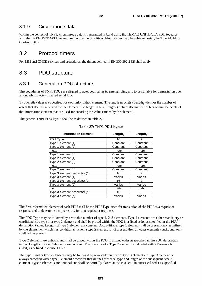
ETSI
ETSI TS 100 392-5 V1.1.1 (2001-07)82
8.1.9 Circuit mode data
Within the context of TNP1, circuit mode data is transmitted in-band using the TEMAC-UNITDATA PDU togetherwith the TNP1-UNITDATA request and indication primitives. Flow control may be achieved using the TEMAC FlowControl PDUs.
8.2 Protocol timersFor MM and CMCE services and procedures, the timers defined in EN 300 392-2 [2] shall apply.
8.3 PDU structure
8.3.1 General on PDU structure
The boundaries of TNP1 PDUs are aligned to octet boundaries to ease handling and to be suitable for transmission overan underlying octet-oriented serial link.
Two length values are specified for each information element. The length in octets (Length8) defines the number ofoctets that shall be reserved for the element. The length in bits (Length2) defines the number of bits within the octets of
the information element that are used for encoding the value carried by the element.
The generic TNP1 PDU layout shall be as defined in table 27.
Table 27: TNP1 PDU layout
Information element Length2 Length8
PDU Type 16 2Type 1 element (1) Constant ConstantType 1 element (2) Constant Constant...etc. …etc. …etc.Type 1 element (n) Constant ConstantType 2 element (1) Constant ConstantType 2 element (2) Constant Constant...etc. …etc. …etc.Type 2 element (n) Constant ConstantType 3 element descriptor (1) 16 2Type 3 element (1) Varies VariesType 3 element descriptor (2) 16 2Type 3 element (2) Varies Varies...etc. …etc. …etc.Type 3 element descriptor (n) 16 2Type 3 element (n) Varies Varies
The first information element of each PDU shall be the PDU Type, used for translation of the PDU as a request orresponse and to determine the peer entity for that request or response.
The PDU Type may be followed by a variable number of type 1, 2, 3 elements. Type 1 elements are either mandatory orconditional to a type 1 or type 2 element and shall be placed within the PDU in a fixed order as specified in the PDUdescription tables. Lengths of type 1 element are constant. A conditional type 1 element shall be present only as definedby the element on which it is conditional. When a type 2 element is not present, then all other elements conditional on itshall not be present.
Type 2 elements are optional and shall be placed within the PDU in a fixed order as specified in the PDU descriptiontables. Lengths of type 2 elements are constant. The presence of a Type 2 element is indicated with a Presence bit(P-bit) as defined in clause 11.5.2.
The type 1 and/or type 2 elements may be followed by a variable number of type 3 elements. A type 3 element isalways preceded with a type 3 element descriptor that defines presence, type and length of the subsequent type 3element. Type 3 Elements are optional and shall be normally placed at the PDU end in numerical order as specified

ETSI
ETSI TS 100 392-5 V1.1.1 (2001-07)83
within the type 3 element identifier. The presence of a Type 3 element is indicated with a presence bit (M-bit) asdefined in clause 11.5.3. Type 3 element coding can contain sub-elements, which can be either of type 1, 2 or 3.
Type 3 element descriptor are not shown in the PDU description tables, nor is their length taken into account in thePDU descriptions.
NOTE: The last existing information element whether type 1, 2 or 3 is not followed either by an O, P or M-bit,contrary to the AI PDU encoding.
The octet and bit ordering within each information element shall be as defined in figure 12. When an informationelement contains more than one octet, the most significant octet (octet 1) containing the Most Significant Bit (MSB) bnof the information element shall be transmitted first. The MSB of an information element can be any of the bits in thatoctet. If the MSB of the information element is not bit number 8, then all bits having a higher bit number shall be set tozero. The Least Significant Bit (LSB) b1 of the information element shall be transmitted as the first bit of the leastsignificant octet (octet n). The bits are numbered within each octet as defined in figure 39. The bit 1 of an octet shall betransmitted first.
8 7 6 5 4 3 2 1 Bit numberbn
(MSB)
bn-1 bn-2 bn-3 bn-4 bn-5 bn-6 bn-7 Octet 1 (mostsignificant octet)
... ... ... ... ... ... ... ... ...etc.
b16 b15 b14 b13 b12 b11 b10 b9 Octet m-1
b8 b7 b6 b5 b4 b3 b2 b1
(LSB)
Octet m (leastsignificant octet)
Figure 12: Octet and bit order in information elements of TNP1 PDUs
8.3.2 Structure and encoding of Type 1 elements
Each type 1 Element has a fixed length within a PDU. The length of the type 1 Element (Length8) in bytes is derived
from the length of the associated information element (Length2) with the following formula:
Length8 = 1 + ((Length2 -1) div 8)
The bits of the associated information element are right aligned to the octets of type 1 element, the least signalled bitpositioned to the bit 1 of the least significant octet. Unused bits of the most significant octet are set to zero.
8.3.3 Structure and encoding of Type 2 elements
Each type 2 Element has a fixed length within a PDU. The length of the type 2 element (Length8) in bytes is derived
from the length of the associated information element (Length2) with the following formula:
Length8 = 1 + ((Length2) div 8)
The bits of the associated information element are right aligned to the octets of the type 2 element, the least signalled bitpositioned to the bit 1 of the least significant octet.
The presence of a valid value in the type 2 element is indicated with a Presence bit (P-bit). The P-Bit is positioned in themost significant bit of the most significant octet (bn of the information element). The P-bit shall be set to "1" to indicate
a present value and "0" to indicate a non-present value. Unused bits of the most significant octet are set to "0".
For a non-present type 2 element, the mapping shall result in Length8 placeholder octet with all bits set to "0".
8.3.4 Structure and encoding of Type 3 elements
A type 3 element is made up of three sub-elements; M bit, element identifier and length.
The M-bit, type 3 element identifier and Length Indicator (LI) of a type 3 element shall be mapped to a two-octet type 3element descriptor preceding the information element itself, as depicted in figure 13.

ETSI
ETSI TS 100 392-5 V1.1.1 (2001-07)84
8 7 6 5 4 3 2 1 bitM-bit Type 3 element identifier LI11 LI10 LI9 Octet 1
LI8 LI7 LI6 LI5 LI4 LI3 LI2 LI1 Octet 2
Figure 13: Structure of type 3 Element Identifier
The presence of a type 3 element is indicated with a more bit (M-bit) placed in bit 8 of octet 1. The M-bit shall be set to"1" if a type 3 element exists and to "0" if not.
If the M-bit is set to "0", then all other bits of the type 3 element descriptor shall be set to zero, too.
The type 3 element identifier can have one of four different sets of values, depending on the type of PDU in which it iscontained. The four sets are CMCE, MM, MTA and SS.
The Length Indicator (LI) is an eleven-bit integer value defining the length of the subsequent type 3 element in bits. Themost significant bit LI11 of the Length Indicator is mapped in bit 3 of octet 1 and the least significant bit LI1 in bit 1 of
octet 2.
The length of the type 3 element in octets (Length8) is derived from the length of the associated information element in
bits (Length2), using the following formula:
Length8 = 1 + ((Length2 - 1) div 8)
The bits of the associated information element are right aligned to the octets of the type 3 element, the least significantbit positioned to the bit 1 of the least significant octet. Unused bits of the most significant octet are set to zero.
Type 3 element coding of a PDU can contain sub-elements that can be either of Type 1, 2 or 3. When sub-elementsexist, the value of Length Indicator in associated Type 3 element identifier shall be set to indicate the total number ofbits contained in the octet-mapped sub-elements, i.e. the value of Length Indicator is the number of octets times 8.
8.4 TNP1 PDU descriptions
8.4.1 General on TNP1 PDU descriptions
The PDUs are designed to map easily onto the primitives defined in EN 300 392-2 [2] at the TNMM-SAP, TNCC-SAP,TNSDS-SAP and TNSDS-TL-SAP. The mapping is not exact, as some supplementary services fields have been addedto the call control PDUs. Supplementary Services PDUs still exist for non-call related services.
In all the tables below the "length" column is left blank if the element is itself made up of other elements (i.e. is astructure). Sometimes the length of the structure is fixed and sometimes it is variable.

ETSI
ETSI TS 100 392-5 V1.1.1 (2001-07)85
8.4.2 CC PDUs
8.4.2.1 TECC-ALERT IND
This PDU shall be used to convey the parameters of TNCC-ALERT indication from MT2 to TE2 as defined in table 28.
Table 28: TECC-ALERT IND PDU contents
Information element Length2 Length8 Type C/O/M Remark
PDU Type 1 MCall handle 16 2 1 MCall time-out, set-up phase 3 1 1 MSimplex/duplex selection 1 1 1 MBasic service information 8 2 2 O noteCall queued 1 1 2 ONotification indicator 6 1 2 OFacility 3 OProprietary 3 ONOTE: If different from requested.
8.4.2.2 TECC-COMPLETE CON
This PDU shall be used to convey the parameters of TNCC-COMPLETE confirm from MT2 to TE2 as defined intable 29.
Table 29: TECC-COMPLETE CON PDU contents
Information element Length2 Length8 Type C/O/M Remark
PDU Type 1 MCall handle 16 2 1 MCall time-out 4 1 1 MTransmission grant 2 1 1 MTransmission request permission 1 1 1 MNotification indicator 6 1 2 OFacility 3 OProprietary 3 O
8.4.2.3 TECC-COMPLETE IND
This PDU shall be used to convey the parameters of TNCC-COMPLETE indication from MT2 to TE2 as defined intable 30.
Table 30: TECC-COMPLETE IND PDU contents
Information element Length2 Length8 Type C/O/M Remark
PDU Type 1 MCall handle 16 2 1 MCall time-out 4 1 1 MTransmission grant 2 1 1 MTransmission request permission 1 1 1 MNotification indicator 6 1 2 OFacility 3 OProprietary 3 O
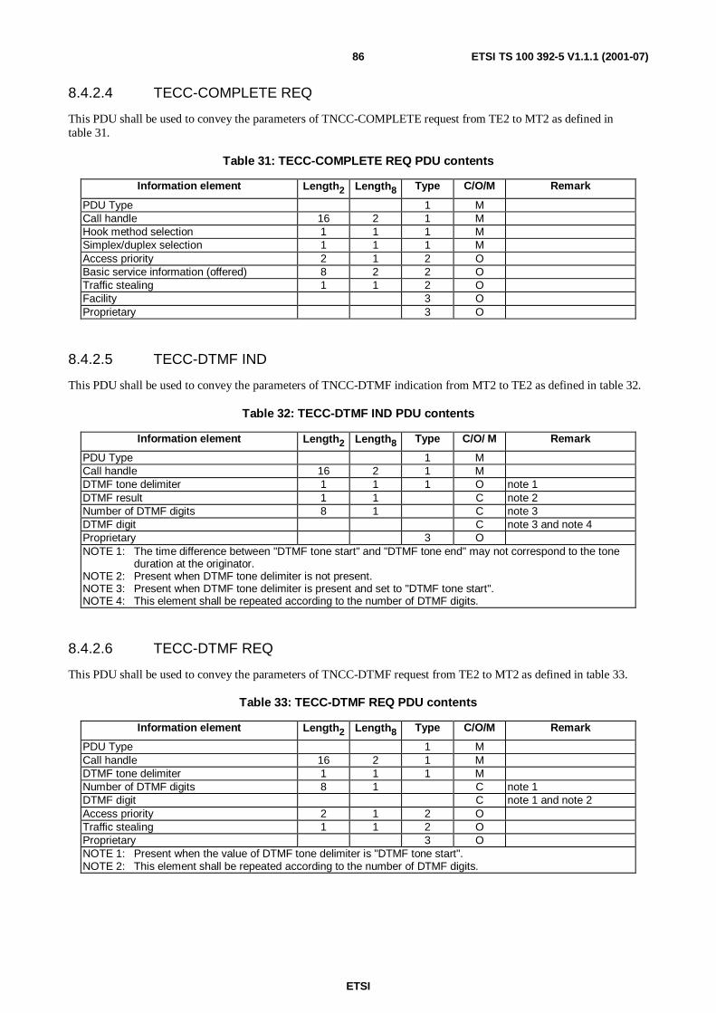
ETSI
ETSI TS 100 392-5 V1.1.1 (2001-07)86
8.4.2.4 TECC-COMPLETE REQ
This PDU shall be used to convey the parameters of TNCC-COMPLETE request from TE2 to MT2 as defined intable 31.
Table 31: TECC-COMPLETE REQ PDU contents
Information element Length2 Length8 Type C/O/M Remark
PDU Type 1 MCall handle 16 2 1 MHook method selection 1 1 1 MSimplex/duplex selection 1 1 1 MAccess priority 2 1 2 OBasic service information (offered) 8 2 2 OTraffic stealing 1 1 2 OFacility 3 OProprietary 3 O
8.4.2.5 TECC-DTMF IND
This PDU shall be used to convey the parameters of TNCC-DTMF indication from MT2 to TE2 as defined in table 32.
Table 32: TECC-DTMF IND PDU contents
Information element Length2 Length8 Type C/O/ M Remark
PDU Type 1 MCall handle 16 2 1 MDTMF tone delimiter 1 1 1 O note 1DTMF result 1 1 C note 2Number of DTMF digits 8 1 C note 3DTMF digit C note 3 and note 4Proprietary 3 ONOTE 1: The time difference between "DTMF tone start" and "DTMF tone end" may not correspond to the tone
duration at the originator.NOTE 2: Present when DTMF tone delimiter is not present.NOTE 3: Present when DTMF tone delimiter is present and set to "DTMF tone start".NOTE 4: This element shall be repeated according to the number of DTMF digits.
8.4.2.6 TECC-DTMF REQ
This PDU shall be used to convey the parameters of TNCC-DTMF request from TE2 to MT2 as defined in table 33.
Table 33: TECC-DTMF REQ PDU contents
Information element Length2 Length8 Type C/O/M Remark
PDU Type 1 MCall handle 16 2 1 MDTMF tone delimiter 1 1 1 MNumber of DTMF digits 8 1 C note 1DTMF digit C note 1 and note 2Access priority 2 1 2 OTraffic stealing 1 1 2 OProprietary 3 ONOTE 1: Present when the value of DTMF tone delimiter is "DTMF tone start".NOTE 2: This element shall be repeated according to the number of DTMF digits.
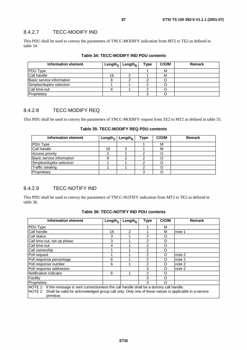
ETSI
ETSI TS 100 392-5 V1.1.1 (2001-07)87
8.4.2.7 TECC-MODIFY IND
This PDU shall be used to convey the parameters of TNCC-MODIFY indication from MT2 to TE2 as defined intable 34.
Table 34: TECC-MODIFY IND PDU contents
Information element Length2 Length8 Type C/O/M Remark
PDU Type 1 MCall handle 16 2 1 MBasic service information 8 2 2 OSimplex/duplex selection 1 1 2 OCall time-out 4 1 2 OProprietary 3 O
8.4.2.8 TECC-MODIFY REQ
This PDU shall be used to convey the parameters of TNCC-MODIFY request from TE2 to MT2 as defined in table 35.
Table 35: TECC-MODIFY REQ PDU contents
Information element Length2 Length8 Type C/O/M Remark
PDU Type 1 MCall handle 16 2 1 MAccess priority 2 1 2 OBasic service information 8 2 2 OSimplex/duplex selection 1 1 2 OTraffic stealing 1 1 2 OProprietary 3 O
8.4.2.9 TECC-NOTIFY IND
This PDU shall be used to convey the parameters of TNCC-NOTIFY indication from MT2 to TE2 as defined intable 36.
Table 36: TECC-NOTIFY IND PDU contents
Information element Length2 Length8 Type C/O/M Remark
PDU Type 1 MCall handle 16 2 1 M note 1Call status 3 1 2 OCall time-out, set-up phase 3 1 2 OCall time-out 4 1 2 OCall ownership 1 1 2 OPoll request 1 1 2 O note 2Poll response percentage 6 1 2 O note 2Poll response number 6 1 2 O note 2Poll response addresses 3 O note 2Notification indicator 6 1 2 OFacility 3 OProprietary 3 ONOTE 1: If the message is sent connectionless the call handle shall be a dummy call handle.NOTE 2: Shall be valid for acknowledged group call only. Only one of these values is applicable in a service
primitive.

ETSI
ETSI TS 100 392-5 V1.1.1 (2001-07)88
8.4.2.10 TECC-PROCEED IND
This PDU shall be used to convey the parameters of TNCC-PROCEED indication from MT2 to TE2 as defined intable 37.
Table 37: TECC-PROCEED IND PDU contents
Information element Length2 Length8 Type C/O/M Remark
PDU Type 1 MCall handle 16 2 1 MBasic service information 8 2 2 O noteCall status 3 1 2 OHook method selection 1 1 2 OSimplex/duplex selection 1 1 2 ONotification indicator 6 1 2 OFacility 3 OProprietary 3 ONOTE: If different from requested.
8.4.2.11 TECC-RELEASE CON
This PDU shall be used to convey the parameters of TNCC-RELEASE confirm from MT2 to TE2 as defined intable 38.
Table 38: TECC-RELEASE CON PDU contents
Information element Length2 Length8 Type C/O/M Remark
PDU Type 1 MCall handle 16 2 1 MDisconnect cause 5 1 1 MDisconnect status 2 1 1 MNotification indicator 6 1 2 OFacility 3 OProprietary 3 O
8.4.2.12 TECC-RELEASE IND
This PDU shall be used to convey the parameters of TNCC-RELEASE indication from MT2 to TE2 as defined intable 39.
Table 39: TECC-RELEASE IND PDU contents
Information element Length2 Length8 Type C/O/M Remark
PDU Type 1 MCall handle 16 2 1 MDisconnect cause 5 1 1 MNotification indicator 6 1 2 OFacility 3 OProprietary 3 O

ETSI
ETSI TS 100 392-5 V1.1.1 (2001-07)89
8.4.2.13 TECC-RELEASE REQ
This PDU shall be used to convey the parameters of TNCC-RELEASE request from TE2 to MT2 as defined in table 40.
Table 40: TECC-RELEASE REQ PDU contents
Information element Length2 Length8 Type C/O/M Remark
PDU Type 1 MCall handle 16 2 1 MDisconnect cause 5 1 1 MDisconnect type 2 1 1 MTraffic stealing 1 1 2 OAccess priority 2 1 2 OFacility 3 OProprietary 3 O
8.4.2.14 TECC-SETUP CON
This PDU shall be used to convey the parameters of TNCC-SETUP confirm from MT2 to TE2 as defined in table 41.
Table 41: TECC-SETUP CON PDU contents
Information element Length2 Length8 Type C/O/M Remark
PDU Type 1 MCall handle 16 2 1 MBasic service information 8 1 1 M noteCall time-out 4 1 1 MHook method selection 1 1 1 MTransmission grant 2 1 1 MTransmission request permission 1 1 1 MCall ownership 1 1 1 MCall amalgamation 2 1 1 MSimplex/duplex selection 1 1 1 MCall priority 4 1 2 ONotification indicator 6 1 2 OFacility 3 OProprietary 3 ONOTE: If different from requested.

ETSI
ETSI TS 100 392-5 V1.1.1 (2001-07)90
8.4.2.15 TECC-SETUP IND
This PDU shall be used to convey the parameters of TNCC-SETUP indication from MT2 to TE2 as defined in table 42.
Table 42: TECC-SETUP IND PDU contents
Information element Length2 Length8 Type C/O/M Remark
PDU Type 1 MCall handle 16 2 1 MHook method selection 1 1 1 MSimplex/duplex selection 1 1 1 MBasic service information 8 1 1 MTransmission grant 2 1 1 MTransmission request permission 1 1 1 MCall priority 4 1 1 MCall time-out 4 1 1 MCalled party type identifier 3 1 1 MCalled party SSI 24 3 C note 1Called party extension 24 3 C note 1Calling party type identifier 2 1 2 OCalling party SSI 24 3 C note 2Calling party extension 24 3 C note 2External subscriber number (calling) MCLIR control 2 1 2 ONotification indicator 6 1 2 OFacility 3 OProprietary 3 ONOTE 1: Shall be conditional on the value of Called Party Type Identifier (CPTI):
- CPTI = 0012; Called Party SSI;- CPTI = 0102; Called Party SSI + Called Party Extension.
NOTE 2: Shall be conditional on the value of Calling Party Identifier (CGPTI):- CGPTI = 012; Calling Party SSI;- CGPTI = 102; Calling Party SSI + Calling Party Extension.

ETSI
ETSI TS 100 392-5 V1.1.1 (2001-07)91
8.4.2.16 TECC-SETUP REQ
This PDU shall be used to convey the parameters of TNCC-SETUP request from TE2 to MT2 as defined in table 43.
Table 43: TECC-SETUP REQ PDU contents
Information element Length2 Length8 Type C/O/M Remark
PDU Type 1 MHook method selection 1 1 1 MSimplex/duplex selection 1 1 1 MBasic service information 8 1 1 MRequest to transmit/send data 1 1 1 MCall priority 4 1 1 MCalled party type identifier 3 1 1 M SNA/SSI/TSICalled party SNA 8 1 C note 1Called party SSI 24 3 C note 1Called party extension 24 3 C note 1External subscriber number (called) MArea selection 4 1 1 O note 2Access priority 2 1 2 O note 3Traffic stealing 1 1 2 O note 4CLIR control 2 1 2 OFacility 3 OProprietary 3 ONOTE 1: Shall be conditional on the value of Called Party Type Identifier (CPTI):
- CPTI = 0002; Called Party SNA;- CPTI = 0012; Called Party SSI;- CPTI = 0102; Called Party SSI + Called Party Extension.
NOTE 2: If not used then the MT2 should use value "not defined"NOTE 3: If not used then the MT2 should use value "low priority"NOTE 4: If not used then the MT2 should use value "no stealing".
8.4.2.17 TECC-SETUP RES
This PDU shall be used to convey the parameters of TNCC-SETUP response from TE2 to MT2 as defined in table 44.
Table 44: TECC-SETUP RES PDU contents
Information element Length2 Length8 Type C/O/M Remark
PDU Type 1 MCall handle 14 2 1 MHook method selection 1 1 1 MSimplex/duplex selection 1 1 2 OBasic service information 8 2 2 OAccess priority 2 1 2 O note 1Traffic stealing 1 1 2 O note 2CLIR control 2 1 2 OFacility 3 OProprietary 3 ONOTE 1: If not used then the MT2 should use value "low priority"NOTE 2: If not used then the MT2 should use value "no stealing".

ETSI
ETSI TS 100 392-5 V1.1.1 (2001-07)92
8.4.2.18 TECC-TX CON
This PDU shall be used to convey the parameters of TNCC-TX confirm from MT2 to TE2 as defined in table 45.
Table 45: TECC-TX CON PDU contents
Information element Length2 Length8 Type C/O/M Remark
PDU Type 1 MCall handle 16 2 1 MTransmission status 2 1 1 MTransmission request permission 1 1 1 MEnd to end encryption flag 1 1 1 MNotification indicator 6 1 2 OFacility 3 OProprietary 3 O
8.4.2.19 TECC-TX IND
This PDU shall be used to convey the parameters of TNCC-TX indication from MT2 to TE2 as defined in table 46.
Table 46: TECC-TX IND PDU contents
Information element Length2 Length8 Type C/O/M Remark
PDU Type 1 MCall handle 14 2 1 MTransmission status 2 1 1 MTransmission request permission 1 1 1 MEnd to end encryption flag 1 1 1 MTransmitting party type identifier 2 1 2 OTransmitting party SSI 24 3 C noteTransmitting party extension 24 3 C noteExternal subscriber number MNotification indicator 6 1 2 OFacility 3 OProprietary 3 ONOTE: Shall be conditional on the value of Transmitting Party Type Identifier (TPTI):
TPTI = 012; Transmitting Party SSI;TPTI = 102; Transmitting Party SSI + Transmitting Party Extension.
8.4.2.20 TECC-TX REQ
This PDU shall be used to convey the parameters of TNCC-TX request from TE2 to MT2 as defined in table 47.
Table 47: TECC-TX REQ PDU contents
Information element Length2 Length8 Type C/O/M Remark
PDU Type 1 MCall handle 16 2 1 MTransmission condition 1 1 1 MTX demand priority 2 1 2 MEnd to end encryption flag 1 1 2 MAccess priority 2 1 2 O note 1Traffic stealing 1 1 2 O note 2Facility 3 OProprietary 3 ONOTE 1: If not used then the MT2 should use value "low priority"NOTE 2: If not used then the MT2 should use value "no stealing".

ETSI
ETSI TS 100 392-5 V1.1.1 (2001-07)93
8.4.3 PDUs for circuit mode data
8.4.3.1 TEMAC-FLOW CONTROL PDU
This PDU shall be used to control circuit mode data rate between TE2 application and MT2 as defined in table 48.
The receiver of data shall transmit this PDU to limit the data to the number of blocks specified. Either the TE or the MTcan use this but the MT will most likely use it as the air interface normally operates at a lower speed than the PEI.
Table 48: TEMAC-FLOW CONTROL PDU contents
Information element Length2 Length8 Type C/O/M Remark
PDU type 1 MMax data 8 1 1 M
8.4.3.2 TEMAC-UNITDATA
This PDU shall be used to transmit circuit mode data between TE2 application and MT2 as defined in table 49.
Table 49: TEMAC-UNITDATA PDU contents
Information element Length2 Length8 Type C/O/M Remark
PDU type 1 MCall identity 14 2 1 MTraffic stealing 1 1 1 MCircuit mode data C
8.4.4 MM PDUs
8.4.4.1 General on MM PDUs
NOTE: TEMM-REGISTRATION PDUs are not recommended to be controlled by the TE application.
8.4.4.2 TEMM-ATTACH DETACH GROUP IDENTITY CON
This PDU shall be used to convey the parameters of TNMM-ATTACH DETACH GROUP IDENTITY confirm fromMT2 to TE2 as defined in table 50.
Table 50: TEMM-ATTACH DETACH GROUP IDENTITY CON PDU contents
Information element Length2 Length8 Type C/O/M Remark
PDU Type 1 MAttach detach request status 3 1 1 MGroup identity attach/detach mode 1 1 1 MNumber of groups 4 1 1 MGroup identity downlink C noteGroup identity report 1 1 2 OProprietary 3 ONOTE: Repeatable according to the Number of groups.
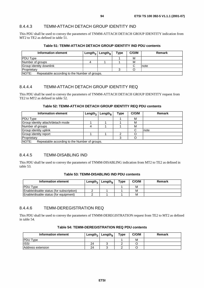
ETSI
ETSI TS 100 392-5 V1.1.1 (2001-07)94
8.4.4.3 TEMM-ATTACH DETACH GROUP IDENTITY IND
This PDU shall be used to convey the parameters of TNMM-ATTACH DETACH GROUP IDENTITY indication fromMT2 to TE2 as defined in table 51.
Table 51: TEMM-ATTACH DETACH GROUP IDENTITY IND PDU contents
Information element Length2 Length8 Type C/O/M Remark
PDU Type 1 MNumber of groups 4 1 1 MGroup identity downlink C noteProprietary 3 ONOTE: Repeatable according to the Number of groups.
8.4.4.4 TEMM-ATTACH DETACH GROUP IDENTITY REQ
This PDU shall be used to convey the parameters of TNMM-ATTACH DETACH GROUP IDENTITY request fromTE2 to MT2 as defined in table 52.
Table 52: TEMM-ATTACH DETACH GROUP IDENTITY REQ PDU contents
Information element Length2 Length8 Type C/O/M Remark
PDU Type 1 MGroup identity attach/detach mode 1 1 1 MNumber of groups 4 1 1 MGroup identity uplink C noteGroup identity report 1 1 2 OProprietary 3 ONOTE: Repeatable according to the Number of groups.
8.4.4.5 TEMM-DISABLING IND
This PDU shall be used to convey the parameters of TNMM-DISABLING indication from MT2 to TE2 as defined intable 53.
Table 53: TEMM-DISABLING IND PDU contents
Information element Length2 Length8 Type C/O/M Remark
PDU Type 1 MEnable/disable status (for subscription) 2 1 1 MEnable/disable status (for equipment) 2 1 1 M
8.4.4.6 TEMM-DEREGISTRATION REQ
This PDU shall be used to convey the parameters of TNMM-DEREGISTRATION request from TE2 to MT2 as definedin table 54.
Table 54: TEMM-DEREGISTRATION REQ PDU contents
Information element Length2 Length8 Type C/O/M Remark
PDU Type 1 MISSI 24 3 2 OAddress extension 24 3 2 O

ETSI
ETSI TS 100 392-5 V1.1.1 (2001-07)95
8.4.4.7 TEMM-ENABLING IND
This PDU shall be used to convey the parameters of TNMM-ENABLING indication from MT2 to TE2 as defined intable 55.
Table 55: TEMM-ENABLING IND PDU contents
Information element Length2 Length8 Type C/O/M Remark
PDU Type 1 MEnable/disable status (for subscription) 2 1 1 MEnable/disable status (for equipment) 2 1 1 M
8.4.4.8 TEMM-ENERGY SAVING CON
This PDU shall be used to convey the parameters of TNMM-ENERGY SAVING confirm from MT2 to TE2 as definedin table 56.
Table 56: TEMM-ENERGY SAVING CON PDU contents
Information element Length2 Length8 Type C/O/M Remark
PDU Type 1 MEnergy economy mode 3 1 1 MEnergy economy mode status 1 1 1 M
8.4.4.9 TEMM-ENERGY SAVING IND
This PDU shall be used to convey the parameters of TNMM-ENERGY SAVING indication from TE2 to MT2 asdefined in table 56.
Table 56: TEMM-ENERGY SAVING IND PDU contents
Information element Length2 Length8 Type C/O/M Remark
PDU Type 1 MEnergy economy mode 3 1 2 OEnergy economy mode status 1 1 2 O
8.4.4.10 TEMM-ENERGY SAVING REQ
This PDU shall be used to convey the parameters of TNMM-ENERGY SAVING request from TE2 to MT2 as definedin table 57.
Table 57: TEMM-ENERGY SAVING REQ PDU contents
Information element Length2 Length8 Type C/O/M Remark
PDU Type 1 MEnergy economy mode 3 1 1 M
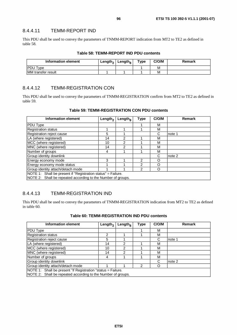
ETSI
ETSI TS 100 392-5 V1.1.1 (2001-07)96
8.4.4.11 TEMM-REPORT IND
This PDU shall be used to convey the parameters of TNMM-REPORT indication from MT2 to TE2 as defined intable 58.
Table 58: TEMM-REPORT IND PDU contents
Information element Length2 Length8 Type C/O/M Remark
PDU Type 1 MMM transfer result 1 1 1 M
8.4.4.12 TEMM-REGISTRATION CON
This PDU shall be used to convey the parameters of TNMM-REGISTRATION confirm from MT2 to TE2 as defined intable 59.
Table 59: TEMM-REGISTRATION CON PDU contents
Information element Length2 Length8 Type C/O/M Remark
PDU Type 1 MRegistration status 1 1 1 MRegistration reject cause 5 1 C note 1LA (where registered) 14 2 1 MMCC (where registered) 10 2 1 MMNC (where registered) 14 2 1 MNumber of groups 4 1 1 MGroup identity downlink C note 2Energy economy mode 3 1 2 OEnergy economy mode status 1 1 2 OGroup identity attach/detach mode 1 1 2 ONOTE 1: Shall be present if "Registration status" = Failure.NOTE 2: Shall be repeated according to the Number of groups.
8.4.4.13 TEMM-REGISTRATION IND
This PDU shall be used to convey the parameters of TNMM-REGISTRATION indication from MT2 to TE2 as definedin table 60.
Table 60: TEMM-REGISTRATION IND PDU contents
Information element Length2 Length8 Type C/O/M Remark
PDU Type 1 MRegistration status 2 1 1 MRegistration reject cause 5 1 C note 1LA (where registered) 14 2 1 MMCC (where registered) 10 2 1 MMNC (where registered) 14 2 1 MNumber of groups 4 1 1 MGroup identity downlink C note 2Group identity attach/detach mode 1 1 2 ONOTE 1: Shall be present "if Registration "status = Failure.NOTE 2: Shall be repeated according to the Number of groups.
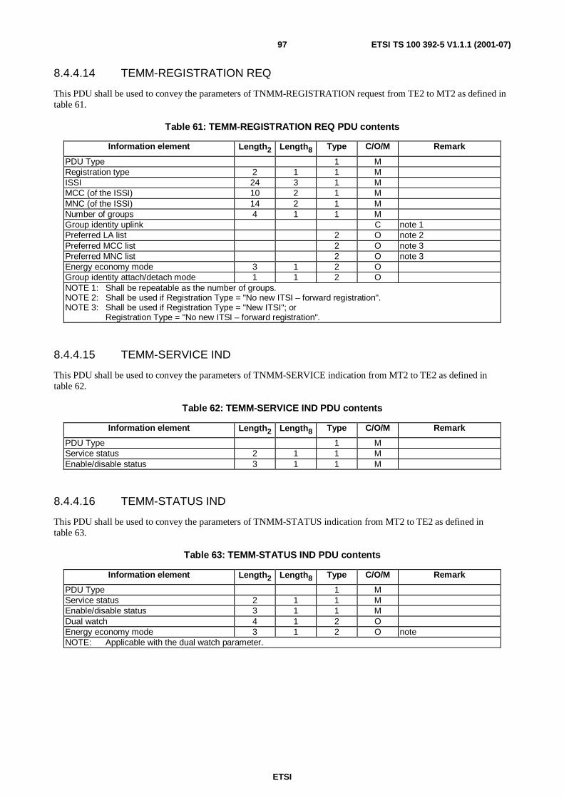
ETSI
ETSI TS 100 392-5 V1.1.1 (2001-07)97
8.4.4.14 TEMM-REGISTRATION REQ
This PDU shall be used to convey the parameters of TNMM-REGISTRATION request from TE2 to MT2 as defined intable 61.
Table 61: TEMM-REGISTRATION REQ PDU contents
Information element Length2 Length8 Type C/O/M Remark
PDU Type 1 MRegistration type 2 1 1 MISSI 24 3 1 MMCC (of the ISSI) 10 2 1 MMNC (of the ISSI) 14 2 1 MNumber of groups 4 1 1 MGroup identity uplink C note 1Preferred LA list 2 O note 2Preferred MCC list 2 O note 3Preferred MNC list 2 O note 3Energy economy mode 3 1 2 OGroup identity attach/detach mode 1 1 2 ONOTE 1: Shall be repeatable as the number of groups.NOTE 2: Shall be used if Registration Type = "No new ITSI – forward registration".NOTE 3: Shall be used if Registration Type = "New ITSI"; or
Registration Type = "No new ITSI – forward registration".
8.4.4.15 TEMM-SERVICE IND
This PDU shall be used to convey the parameters of TNMM-SERVICE indication from MT2 to TE2 as defined intable 62.
Table 62: TEMM-SERVICE IND PDU contents
Information element Length2 Length8 Type C/O/M Remark
PDU Type 1 MService status 2 1 1 MEnable/disable status 3 1 1 M
8.4.4.16 TEMM-STATUS IND
This PDU shall be used to convey the parameters of TNMM-STATUS indication from MT2 to TE2 as defined intable 63.
Table 63: TEMM-STATUS IND PDU contents
Information element Length2 Length8 Type C/O/M Remark
PDU Type 1 MService status 2 1 1 MEnable/disable status 3 1 1 MDual watch 4 1 2 OEnergy economy mode 3 1 2 O noteNOTE: Applicable with the dual watch parameter.

ETSI
ETSI TS 100 392-5 V1.1.1 (2001-07)98
8.4.4.17 TEMM-STATUS CON
This PDU shall be used to convey the parameters of TNMM-STATUS confirm from MT2 to TE2 as defined in table 64.
Table 64: TEMM-STATUS CON PDU contents
Information element Length2 Length8 Type C/O/M Remark
PDU Type 1 MDual watch 4 1 2 OEnergy economy mode 3 1 2 O noteNOTE: Applicable with the dual watch parameter.
8.4.4.18 TEMM-STATUS REQ
This PDU shall be used to convey the parameters of TNMM-STATUS request from TE2 to MT2 as defined in table 65.
Table 65: TEMM-STATUS REQ PDU contents
Information element Length2 Length8 Type C/O/M Remark
PDU Type 1 MDirect mode 1 1 2 ODual watch 4 1 2 OEnergy economy mode 3 1 2 O noteNOTE: Applicable with the dual watch parameter.
8.4.5 MT Application PDUs
8.4.5.1 TEMTA- Services CAPABILITY RESP
This PDU shall be used to convey the parameters of TNP1- SERVICES CAPABILITY response from MT2 to TE2 asdefined in table 66.
Table 66: TEMTA-SERVICES CAPABILITY RESP PDU contents
Information element Length2 Length8 Type C/O/M Remark
PDU Type 1 MCircuit mode and MS services 24 3 1 MSecurity 1 MSDS mode services 4 1 MPacket mode services 4 1 1 MReserved 8 1 1 MProprietary 3 ONOTE: Reserved for future indication of capabilities (e.g. transaction protocol).

ETSI
ETSI TS 100 392-5 V1.1.1 (2001-07)99
8.4.5.2 TEMTA- SDS-TL CAPABILITY RESP
This PDU shall be used to convey the parameters of TNP1- SDS-TL CAPABILITY response from MT2 to TE2 asdefined in table 67.
Table 67: TEMTA-SDS-TL CAPABILITY RESP PDU contents
Information element Length2 Length8 Type C/O/M Remark
PDU Type 1 MSDS-TL service capability 1 1 1 MSDS-TL Service centre capability 1 1 C note 1Store and forward PDU capability 3 1 C note 1, note 2SDS-TL service centre default address C note 1, note 2Proprietary 3 ONOTE 1: Shall be conditional on the value of the SDS-TL service capability (SDS-TLC):
- SDS-TLC = 0;- SDS-TLC = 1;- SDS-TL service centre capability.
NOTE 2: Shall be conditional on the value of the SDS-TL Service centre capability (SDS-TLSC):- SDS-TLSC= 0;- SDS-TLSC=1;- SDS-TL service centre default address + Store and forward PDU capability.
8.4.5.3 TEMTA- Services CAPABILITY REQ
This PDU shall be used to convey the parameters of TNP1-SERVICES CAPABILITY request from TE2 to MT2 asdefined in table 68.
Table 68: TEMTA-SERVICES CAPABILITY REQ PDU contents
Information element Length2 Length8 Type C/O/M Remark
PDU Type 1 M
8.4.5.4 TEMTA- SDS-TL CAPABILITY REQ
This PDU shall be used to convey the parameters of TNP1- SDS-TL CAPABILITY request from TE2 to MT2 asdefined in table 69.
Table 69: TEMTA-SDS-TL CAPABILITY REQ PDU contents
Information element Length2 Length8 Type C/O/M Remark
PDU Type 1 M

ETSI
ETSI TS 100 392-5 V1.1.1 (2001-07)100
8.4.5.5 TEMTA- IDENTITIES RESP
This PDU shall be used to convey the identities information elements from the MT2 to TE2 as defined in table 70.
Table 70: TEMTA-IDENTITIES RESP PDU contents
Information element Length2 Length8 Type C/O/M Remark
PDU Type 1 MITSI 1 MNumber of static groups 4 1 1 MGTSI C note 1Number of dynamic groups 8 1 1 MGTSI C note 2More information flag 1 1 1 M note 3NOTE 1: Shall be repeated as defined by the number of static groups.NOTE 2: Shall be repeated as defined by the number of dynamic groups.NOTE 3: If this flag is set to "yes" the TE shall not send any more commands until all identities have been
returned by the MT (flag set to "no").
8.4.5.6 TEMTA- IDENTITIES REQ
This PDU shall be used to request the identities information elements from the MT2 as defined in table 71.
Table 71: TEMTA-IDENTITIES REQ PDU contents
Information element Length2 Length8 Type C/O/M Remark
PDU Type 1 M
8.4.5.7 TEMTA-SETVOLUME REQ
This PDU shall be used to control the volume setting from the TE2 as defined in table 72.
Table 72: TEMTA-SETVOLUME REQ PDU contents
Information element Length2 Length8 Type C/O/M Remark
PDU Type 1 MVolume level 6 1 1 M
8.4.5.8 TEMTA-SPEAKER-MIC REQ
This PDU shall be used to control the speaker/microphone from the TE2 as defined in table 73.
Table 73: TEMTA-SETVOLUME REQ PDU contents
Information element Length2 Length8 Type C/O/M Remark
PDU Type 1 MSpeaker on off 1 1 2 OMicrophone on off 1 1 2 O

ETSI
ETSI TS 100 392-5 V1.1.1 (2001-07)101
8.4.5.9 TEMTA- SYSINFO RESP
This PDU shall be used to convey the Sysinfo information elements from the MT2 to TE2 as defined in table 74.
Table 74: TEMTA-SYSINFO RESP PDU contents
Information element Length2 Length8 Type C/O/M Remark
PDU Type 1 MSecurity information 8 1 1 MBS service details 12 2 1 MNOTE: The MT will send this PDU on TE request or on any change in the broadcast information.
8.4.5.10 TEMTA- SYSINFO REQ
This PDU shall be used to request the Sysinfo information elements from the TE2 to MT2 as defined in table 75.
Table 75: TEMTA-SYSINFO REQ PDU contents
Information element Length2 Length8 Type C/O/M Remark
PDU Type 1 M
8.4.5.11 TEMTA-IDENTIFICATION RESP
This PDU shall be used to convey the parameters of TNP1-IDENTIFICATION response from MT2 to TE2 as definedin table 76.
Table 76: TEMTA-IDENTIFICATION RESP PDU contents
Information element Length2 Length8 Type C/O/M Remark
PDU type 1 MTerminal equipment identity 60 8 1 MManufacturer Identifier 3 MModel 3 MSoftware version 3 MHardware version 3 OProduct serial number 3 OISO global object ID 3 OTNP1 protocol version 3 OTNP1 release 3 O noteProprietary 3 ONOTE: The TNP1 release shall inform the TE2 user application about the MT2 TNP1 release as defined in the
following table. This parameter shall not be restricted by the standard (Every manufacture can use thisfield for his purposes).
8.4.5.12 TEMTA-IDENTIFICATION REQ
This PDU shall be used to convey the parameters of TNP1-IDENTIFICATION request from TE2 to MT2 as defined intable 77.
Table 77: TEMTA-IDENTIFICATION REQ PDU contents
Information element Length2 Length8 Type C/O/M Remark
PDU Type M

ETSI
ETSI TS 100 392-5 V1.1.1 (2001-07)102
8.4.5.13 TEMTA-SDS STACK MESSAGES
8.4.5.13.1 General on TEMA-SDS stack messages
All incoming/outgoing SDS messages (from / to the air interface) may be stored on a message stack in the MT. Thereare two stacks, as defined in [17], one for Status, SDSS type 1/2/3 and another for SDS4 messages.
Each stack should have 255 entries, each of which has the following fields:
SDS type – Status, SDS Type 1/2/3/4
SDS message format in the SDS stacks, as described in [17] clause 10.3.42 (for SDS4) and in clause 10.3.41 (for SDSstatus/1/2/3).
8.4.5.13.2 TEMTA-SDS DELETE MESSAGES
This PDU shall be used to delete from an MT2 a list of SDS messages in the SDS message stack as defined in table 78.
Table 78: TEMTA-SDS DELETE MESSAGES REQ PDU contents
Information element Length2 Length8 Type C/O/M Remark
PDU Type 1 MSDS type 3 1 1 MNumber of messages 8 1 1 MMessage index 16 1 C note 1, note 2NOTE 1: Shall be repeated as defined by the number of messages to be deleted.NOTE 2: The index is a record for each message that will be used to point to the SDS message in the stack.
8.4.5.13.3 TEMTA-SDS MESSAGE ERROR
This PDU shall be a response from the MT2 to SDS message error in the SDS message stack as defined in table 79.
Table 79: TEMTA-SDS MESSAGE ERROR PDU contents
Information element Length2 Length8 Type C/O/M Remark
PDU Type 1 MSDS type 3 1 1 MMessage index 16 1 1 M noteSDS error 3 1 1 M noteNOTE: This message shall be used as a response to Request message if the request is not valid.
8.4.5.13.4 TEMTA-SDS MESSAGES IND
This PDU shall be used to convey an SDS message in the SDS message stack from MT2 to TE2 as defined in table 80.
Table 80: TEMTA-SDS MESSAGE IND PDU contents
Information element Length2 Length8 Type C/O/M Remark
PDU Type 1 MSDS type 3 1 1 MSDS or SDS-TL data message M noteNOTE: The format shall be as described in [17] clause 10.3.42 for SDS4 and in clause 10.3.41 for SDS
status/1/2/3.

ETSI
ETSI TS 100 392-5 V1.1.1 (2001-07)103
8.4.5.13.5 TEMTA-SDS MESSAGE REQ
This PDU shall be used to request from a MT2 an SDS message in the SDS message stack as defined in table 81.
Table 81: TEMTA-SDS MESSAGE REQ PDU contents
Information element Length2 Length8 Type C/O/M Remark
PDU Type 1 MMessage index 16 1 1 M
8.4.5.13.6 TEMTA-SDS GET LIST BY KEY MESSAGES
This PDU is used to access to SDS messages that are satisfied to given key(s). As a result a list of indexes of therelevant messages will be sent to the application.
Table 82: TEMTA-SDS MESSAGE GET LIST MESSAGES PDU contents
Information element Length2 Length8 Type C/O/M Remark
PDU Type 1 MKey mask 4 1 1 MSDS type 3 1 C noteMessage status 3 1 C noteNOTE: Shall be conditional on the value of key mask information element.
8.4.5.13.7 TEMTA-SDS LIST MESSAGES REPLY
This PDU shall be used as a reply to delete request or to get list messages as defined in table 83. The SDS messageidentity shall contain all the deleted messages with their new status.
Table 83: TEMTA-SDS LIST MESSAGES REPLY PDU contents
Information element Length2 Length8 Type C/O/M Remark
PDU Type 1 MNumber of messages 8 1 1 MMessage index 16 1 1 M noteSDS message status 3 1 1 M noteSDS type 3 1 1 M noteNOTE: Shall be repeated as defined by the number of messages information element.
8.4.5.13.8 TEMTA-SDS NOTIFICATION
This PDU shall be used as a notification to the user application about "message stack full" or a downlink message wasreceived in the message stack, as defined in table 84.
Table 84: TEMTA-SDS NOTIFICATION PDU contents
Information element Length2 Length8 Type C/O/M Remark
PDU Type 1 MSDS type 3 1 1 M noteSDS notification 1 1 1 MNOTE: The SDS type is used to indicate the appropriate stack.
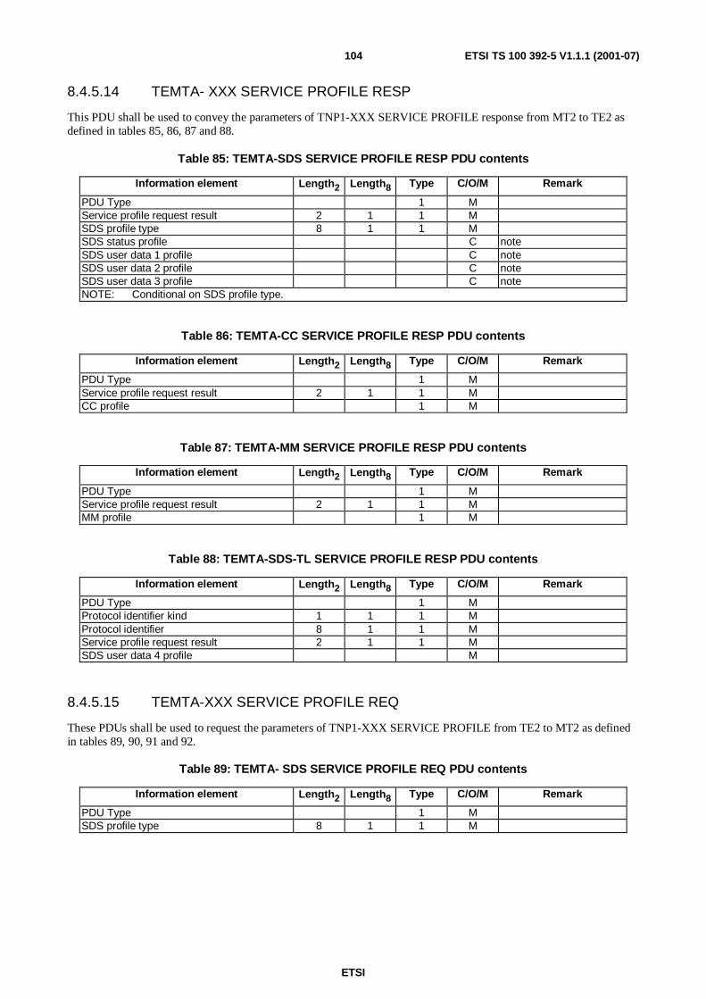
ETSI
ETSI TS 100 392-5 V1.1.1 (2001-07)104
8.4.5.14 TEMTA- XXX SERVICE PROFILE RESP
This PDU shall be used to convey the parameters of TNP1-XXX SERVICE PROFILE response from MT2 to TE2 asdefined in tables 85, 86, 87 and 88.
Table 85: TEMTA-SDS SERVICE PROFILE RESP PDU contents
Information element Length2 Length8 Type C/O/M Remark
PDU Type 1 MService profile request result 2 1 1 MSDS profile type 8 1 1 MSDS status profile C noteSDS user data 1 profile C noteSDS user data 2 profile C noteSDS user data 3 profile C noteNOTE: Conditional on SDS profile type.
Table 86: TEMTA-CC SERVICE PROFILE RESP PDU contents
Information element Length2 Length8 Type C/O/M Remark
PDU Type 1 MService profile request result 2 1 1 MCC profile 1 M
Table 87: TEMTA-MM SERVICE PROFILE RESP PDU contents
Information element Length2 Length8 Type C/O/M Remark
PDU Type 1 MService profile request result 2 1 1 MMM profile 1 M
Table 88: TEMTA-SDS-TL SERVICE PROFILE RESP PDU contents
Information element Length2 Length8 Type C/O/M Remark
PDU Type 1 MProtocol identifier kind 1 1 1 MProtocol identifier 8 1 1 MService profile request result 2 1 1 MSDS user data 4 profile M
8.4.5.15 TEMTA-XXX SERVICE PROFILE REQ
These PDUs shall be used to request the parameters of TNP1-XXX SERVICE PROFILE from TE2 to MT2 as definedin tables 89, 90, 91 and 92.
Table 89: TEMTA- SDS SERVICE PROFILE REQ PDU contents
Information element Length2 Length8 Type C/O/M Remark
PDU Type 1 MSDS profile type 8 1 1 M

ETSI
ETSI TS 100 392-5 V1.1.1 (2001-07)105
Table 90: TEMTA- CC SERVICE PROFILE REQ PDU contents
Information element Length2 Length8 Type C/O/M Remark
PDU Type 1 M
Table 91: TEMTA- MM SERVICE PROFILE REQ PDU contents
Information element Length2 Length8 Type C/O/M Remark
PDU Type 1 M
Table 92: TEMTA- SDS-TL SERVICE PROFILE REQ PDU contents
Information element Length2 Length8 Type C/O/M Remark
PDU Type 1 MProtocol identifier kind 1 1 1 MProtocol identifier 8 1 1 M
8.4.5.16 TEMTA- XXX SERVICE PROFILE SET
This PDU shall be used to convey the parameters of TNP1-XXX SERVICE PROFILE request from TE2 to MT2 asdefined in tables 93, 94, 95 and 96.
Table 93: TEMTA- SDS SERVICE PROFILE SET PDU contents
Information element Length2 Length8 Type C/O/M Remark
PDU Type 1 MSDS profile type 8 MSet profile request 8 MSDS status profile C noteSDS user data 1 profile C noteSDS user data 2 profile C noteSDS user data 3 profile C noteNOTE: Conditional on SDS profile type and set profile request.
Table 94: TEMTA- CC SERVICE PROFILE SET PDU contents
Information element Length2 Length8 Type C/O/M Remark
PDU Type MSet profile request 8 1 1 MCC profile C noteNOTE: Conditional on set profile request.
Table 95: TEMTA- MM SERVICE PROFILE SET PDU contents
Information element Length2 Length8 Type C/O/M Remark
PDU Type 1 MSet profile request 8 1 1 MMM profile 1 C noteNOTE: Conditional on set profile request.

ETSI
ETSI TS 100 392-5 V1.1.1 (2001-07)106
Table 96: TEMTA- SDS-TL SERVICE PROFILE SET PDU contents
Information element Length2 Length8 Type C/O/M Remark
PDU Type 1 MProtocol identifier kind 1 1 1 MProtocol identifier 8 1 1 MSet profile request 8 1 1 MSDS user data 4 profile C noteNOTE: Conditional on set profile request.
8.4.5.17 TEMTA-STATE RESP
This PDU shall be used to convey the parameters of TNP1-STATE response from MT2 to TE2 as defined in table 97.
Table 97: TEMTA-STATE RESP PDU contents
Information element Length2 Length8 Type C/O/M Remark
PDU Type 1 MBattery charge 8 1 1 MField Strength 10 2 1 MBit error rate 8 1 1 MInternal temperature 2 OOver temperature indication 1 1 2 OProprietary 3 O
8.4.5.18 TEMTA-STATE REQ
This PDU shall be used to convey the parameters of TNP1-STATE request from TE2 to MT2 as defined in table 98.
Table 98: TEMTA-STATE REQ PDU contents
Information element Length2 Length8 Type C/O/M Remark
PDU Type 1 M
8.4.5.19 TEMTA-REPORT IND
This PDU shall be used to convey the parameters of TNP1-REPORT primitive from either the TE2 to MT2 or viceversa, as defined in table 99.
Table 99: TEMTA-REPORT IND PDU contents
Information element Length2 Length8 Type C/O/M Remark
PDU Type 1 MReport reason 8 1 1 MPDU type (*) 16 2 1 M noteNOTE: This information element shall contain the PDU type of the unrecognized, received PDU, to which this
message is the reply.
NOTE: Neither TE nor MT shall send more than two successive failure reports. In this event it is considered thelink, applications or DLL are not working and the link shall be declared as failed.
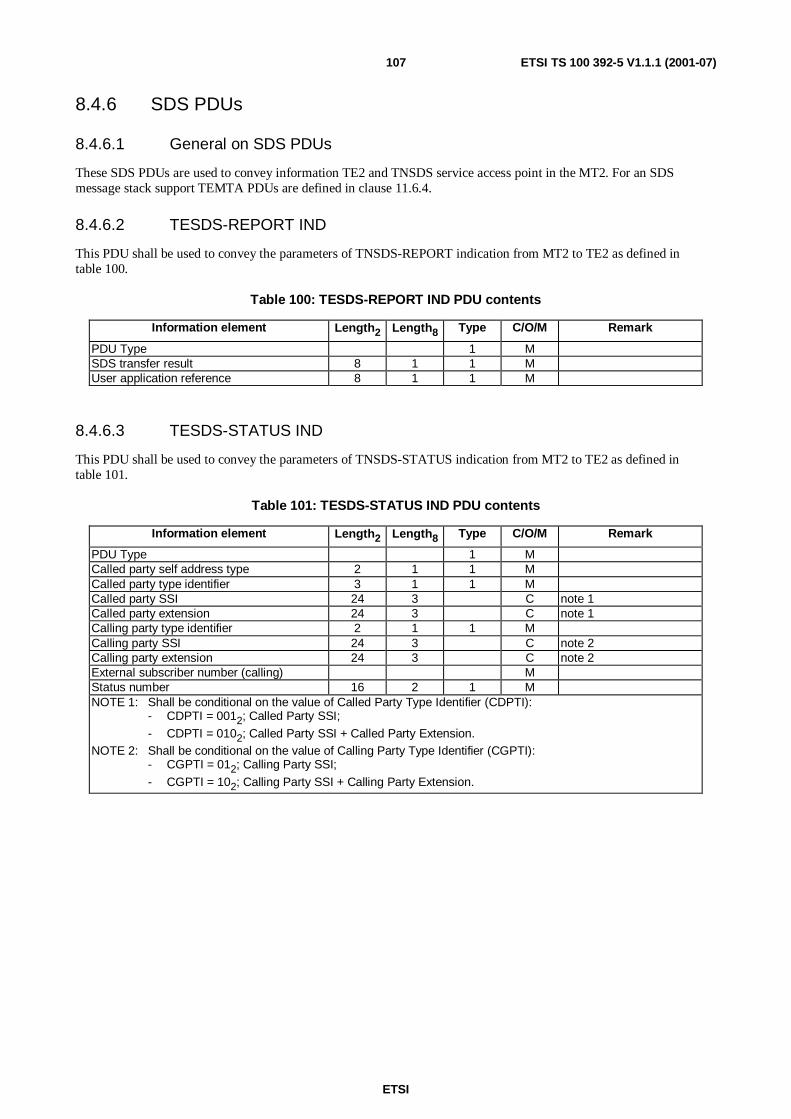
ETSI
ETSI TS 100 392-5 V1.1.1 (2001-07)107
8.4.6 SDS PDUs
8.4.6.1 General on SDS PDUs
These SDS PDUs are used to convey information TE2 and TNSDS service access point in the MT2. For an SDSmessage stack support TEMTA PDUs are defined in clause 11.6.4.
8.4.6.2 TESDS-REPORT IND
This PDU shall be used to convey the parameters of TNSDS-REPORT indication from MT2 to TE2 as defined intable 100.
Table 100: TESDS-REPORT IND PDU contents
Information element Length2 Length8 Type C/O/M Remark
PDU Type 1 MSDS transfer result 8 1 1 MUser application reference 8 1 1 M
8.4.6.3 TESDS-STATUS IND
This PDU shall be used to convey the parameters of TNSDS-STATUS indication from MT2 to TE2 as defined intable 101.
Table 101: TESDS-STATUS IND PDU contents
Information element Length2 Length8 Type C/O/M Remark
PDU Type 1 MCalled party self address type 2 1 1 MCalled party type identifier 3 1 1 MCalled party SSI 24 3 C note 1Called party extension 24 3 C note 1Calling party type identifier 2 1 1 MCalling party SSI 24 3 C note 2Calling party extension 24 3 C note 2External subscriber number (calling) MStatus number 16 2 1 MNOTE 1: Shall be conditional on the value of Called Party Type Identifier (CDPTI):
- CDPTI = 0012; Called Party SSI;
- CDPTI = 0102; Called Party SSI + Called Party Extension.NOTE 2: Shall be conditional on the value of Calling Party Type Identifier (CGPTI):
- CGPTI = 012; Calling Party SSI;
- CGPTI = 102; Calling Party SSI + Calling Party Extension.

ETSI
ETSI TS 100 392-5 V1.1.1 (2001-07)108
8.4.6.4 TESDS-STATUS REQ
This PDU shall be used to convey the parameters of TNSDS-STATUS request from TE2 to MT2 as defined intable 102.
Table 102: TESDS-STATUS REQ PDU contents
Information element Length2 Length8 Type C/O/M Remark
PDU Type 1 MCalled party type identifier 3 1 1 MCalled party SNA 8 1 C noteCalled party SSI 24 3 C noteCalled party extension 24 3 C noteExternal subscriber number (called) C noteUser application reference 8 1 1 MStatus number 16 2 1 MAccess priority 2 1 2 OTraffic stealing 1 1 2 OArea selection 4 1 2 ONOTE: Shall be conditional on the value of Called Party Type Identifier (CPTI):
- CPTI = 0002; Called Party SNA;
- CPTI = 0012; Called Party SSI;
- CPTI = 0102; Called Party SSI + Called Party Extension;
- CPTI = 1002; MT2 default gateway address.
8.4.6.5 TESDS-UNITDATA IND
This PDU shall be used to convey the parameters of TNSDS-UNITDATA indication from MT2 to TE2 as defined intable 103.
Table 103: TESDS-UNITDATA IND PDU contents
Information element Length2 Length8 Type C/O/M Remark
PDU Type 1 MCalled party self address type 2 1 1 MCalled party type identifier 3 1 1 MCalled party SSI 24 3 C note 1Called party extension 24 3 C note 1Calling party type identifier 2 1 1 MCalling party SSI 24 3 C note 2Calling party extension 24 3 C note 2(Calling) external subscriber number C note 2Short data type identifier 2 1 1 MUser defined data-1 16 2 C note 3User defined data-2 32 4 C note 3User defined data-3 64 8 C note 3NOTE 1: Shall be conditional on the value of Called Party Type Identifier (CDPTI):
- CDPTI = 0012; Called Party SSI;
- CDPTI = 0102; Called Party SSI + Called Party Extension.NOTE 2: Shall be conditional on the value of Calling Party Type Identifier (CGPTI):
- CGPTI = 012; Calling Party SSI;
- CGPTI = 102; Calling Party SSI + Calling Party Extension.
NOTE 3: Shall be conditional on the value of Short Data Type Identifier (SDTI):- SDTI = 0; User Defined Data-1;- SDTI = 1; User Defined Data-2;- SDTI = 2; User Defined Data-3.
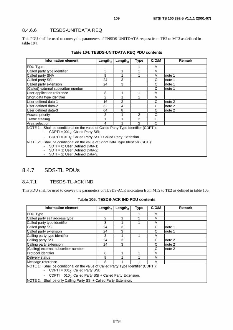
ETSI
ETSI TS 100 392-5 V1.1.1 (2001-07)109
8.4.6.6 TESDS-UNITDATA REQ
This PDU shall be used to convey the parameters of TNSDS-UNITDATA request from TE2 to MT2 as defined intable 104.
Table 104: TESDS-UNITDATA REQ PDU contents
Information element Length2 Length8 Type C/O/M Remark
PDU Type 1 MCalled party type identifier 3 1 1 MCalled party SNA 8 1 1 M note 1Called party SSI 24 3 C note 1Called party extension 24 3 C note 1(Called) external subscriber number C note 1User application reference 8 1 1 MShort data type identifier 2 1 1 MUser defined data-1 16 2 C note 2User defined data-2 32 4 C note 2User defined data-3 64 8 C note 2Access priority 2 1 2 OTraffic stealing 1 1 2 OArea selection 4 1 2 ONOTE 1: Shall be conditional on the value of Called Party Type Identifier (CDPTI):
- CDPTI = 0012; Called Party SSI;
- CDPTI = 0102; Called Party SSI + Called Party Extension.
NOTE 2: Shall be conditional on the value of Short Data Type Identifier (SDTI):- SDTI = 0; User Defined Data-1;- SDTI = 1; User Defined Data-2;- SDTI = 2; User Defined Data-3.
8.4.7 SDS-TL PDUs
8.4.7.1 TESDS-TL-ACK IND
This PDU shall be used to convey the parameters of TLSDS-ACK indication from MT2 to TE2 as defined in table 105.
Table 105: TESDS-ACK IND PDU contents
Information element Length2 Length8 Type C/O/M Remark
PDU Type 1 MCalled party self address type 2 1 1 MCalled party type identifier 3 1 1 MCalled party SSI 24 3 C note 1Called party extension 24 3 C note 1Calling party type identifier 3 1 1 MCalling party SSI 24 3 C note 2Calling party extension 24 3 C note 2(Calling) external subscriber number C note 2Protocol identifier 8 1 1 MDelivery status 8 1 1 MMessage reference 8 1 1 MNOTE 1: Shall be conditional on the value of Called Party Type Identifier (CDPTI):
- CDPTI = 0012; Called Party SSI;
- CDPTI = 0102; Called Party SSI + Called Party Extension.NOTE 2: Shall be only Calling Party SSI + Called Party Extension.
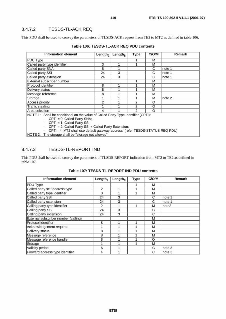
ETSI
ETSI TS 100 392-5 V1.1.1 (2001-07)110
8.4.7.2 TESDS-TL-ACK REQ
This PDU shall be used to convey the parameters of TLSDS-ACK request from TE2 to MT2 as defined in table 106.
Table 106: TESDS-TL-ACK REQ PDU contents
Information element Length2 Length8 Type C/O/M Remark
PDU Type 1 MCalled party type identifier 3 1 1 MCalled party SNA 8 1 C note 1Called party SSI 24 3 C note 1Called party extension 24 3 C note 1External subscriber number 1 MProtocol identifier 8 1 1 MDelivery status 8 1 1 MMessage reference 8 1 1 MStorage 1 1 1 M note 2Access priority 2 1 2 OTraffic stealing 1 1 2 OArea selection 4 1 2 ONOTE 1: Shall be conditional on the value of Called Party Type Identifier (CPTI):
- CPTI = 0; Called Party SNA;- CPTI = 1; Called Party SSI;- CPTI = 2; Called Party SSI + Called Party Extension;- CPTI =4; MT2 shall use default gateway address (refer TESDS-STATUS REQ PDU).
NOTE 2: The storage shall be "storage not allowed".
8.4.7.3 TESDS-TL-REPORT IND
This PDU shall be used to convey the parameters of TLSDS-REPORT indication from MT2 to TE2 as defined intable 107.
Table 107: TESDS-TL-REPORT IND PDU contents
Information element Length2 Length8 Type C/O/M Remark
PDU Type 1 MCalled party self address type 2 1 1 MCalled party type identifier 3 1 1 MCalled party SSI 24 3 C note 1Called party extension 24 3 C note 1Calling party type identifier 2 1 1 M note2Calling party SSI 24 3 CCalling party extension 24 3 CExternal subscriber number (calling) MProtocol identifier 8 1 1 MAcknowledgement required 1 1 1 MDelivery status 8 1 1 MMessage reference 8 1 1 MMessage reference handle 8 1 1 OStorage 1 1 1 MValidity period 6 1 C note 3Forward address type identifier 4 1 C note 3

ETSI
ETSI TS 100 392-5 V1.1.1 (2001-07)111
Information element Length2 Length8 Type C/O/M Remark
Forward address SNA 8 1 C note 3, note 4Forward address SSI 24 3 C note 3, note 4Forward address extension 24 3 C note 3, note 4Forward address external subscribernumber
C note 3, note 4
User data Variable MNOTE 1: Shall be conditional on the value of Called Party Type Identifier (CPTI):
- CPTI = 1; Called Party SSI;- CPTI = 2; Called Party SSI + Called Party Extension.
NOTE 2: Shall be only Calling Party SSI + Calling Party Extension.NOTE 3: Shall be conditional on the value of Storage:
- Storage = 0;- Storage = 1;- Validity period + Forward address.
NOTE 4: Shall be conditional on the value of Forward address Type Identifier (FATI):- FATI = 0; Forward Address SNA;- FATI = 1; Forward Address SSI;- FATI = 2, Forward Address SSI + Forward Address Extension;- FATI = 3; Forward External subscriber number.
8.4.7.4 TESDS-TL-REPORT REQ
This PDU shall be used to convey the parameters of TLSDS-REPORT request from TE2 to MT2 as defined intable 108.
Table 108: TESDS-TL-REPORT REQ PDU contents
Information element Length2 Length8 Type C/O/M Remark
PDU Type 1 MCalled party type identifier 3 1 1 MCalled party SNA 8 1 C note 1Called party SSI 24 3 C note 1Called party extension 24 3 C note 1External subscriber number MProtocol identifier 8 1 1 MAcknowledgement required 1 1 1 MDelivery status 8 1 1 MMessage reference 8 1 1 MShort form report 8 1 1 MStorage 1 1 1 MValidity period 6 1 C note 2Forward address type identifier 4 1 C note 2Forward address SNA 8 1 C note 2, note 3Forward address SSI 24 3 C note 2, note 3Forward address extension 24 3 C note 2, note 3Forward address external subscribernumber
C note 2, note 3
Access priority 2 1 2 OTraffic stealing 1 1 2 O
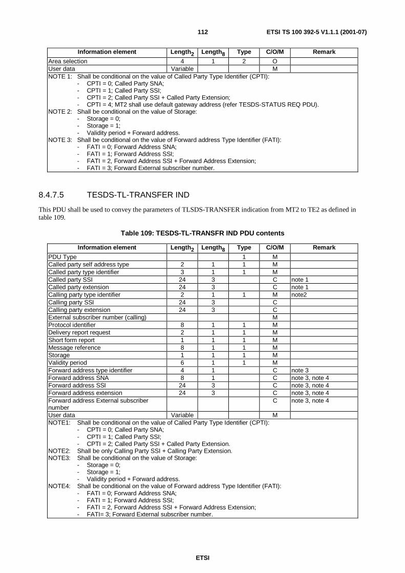
ETSI
ETSI TS 100 392-5 V1.1.1 (2001-07)112
Information element Length2 Length8 Type C/O/M Remark
Area selection 4 1 2 OUser data Variable MNOTE 1: Shall be conditional on the value of Called Party Type Identifier (CPTI):
- CPTI = 0; Called Party SNA;- CPTI = 1; Called Party SSI;- CPTI = 2; Called Party SSI + Called Party Extension;- CPTI = 4; MT2 shall use default gateway address (refer TESDS-STATUS REQ PDU).
NOTE 2: Shall be conditional on the value of Storage:- Storage = 0;- Storage = 1;- Validity period + Forward address.
NOTE 3: Shall be conditional on the value of Forward address Type Identifier (FATI):- FATI = 0; Forward Address SNA;- FATI = 1; Forward Address SSI;- FATI = 2, Forward Address SSI + Forward Address Extension;- FATI = 3; Forward External subscriber number.
8.4.7.5 TESDS-TL-TRANSFER IND
This PDU shall be used to convey the parameters of TLSDS-TRANSFER indication from MT2 to TE2 as defined intable 109.
Table 109: TESDS-TL-TRANSFR IND PDU contents
Information element Length2 Length8 Type C/O/M Remark
PDU Type 1 MCalled party self address type 2 1 1 MCalled party type identifier 3 1 1 MCalled party SSI 24 3 C note 1Called party extension 24 3 C note 1Calling party type identifier 2 1 1 M note2Calling party SSI 24 3 CCalling party extension 24 3 CExternal subscriber number (calling) MProtocol identifier 8 1 1 MDelivery report request 2 1 1 MShort form report 1 1 1 MMessage reference 8 1 1 MStorage 1 1 1 MValidity period 6 1 1 MForward address type identifier 4 1 C note 3Forward address SNA 8 1 C note 3, note 4Forward address SSI 24 3 C note 3, note 4Forward address extension 24 3 C note 3, note 4Forward address External subscribernumber
C note 3, note 4
User data Variable MNOTE1: Shall be conditional on the value of Called Party Type Identifier (CPTI):
- CPTI = 0; Called Party SNA;- CPTI = 1; Called Party SSI;- CPTI = 2; Called Party SSI + Called Party Extension.
NOTE2: Shall be only Calling Party SSI + Calling Party Extension.NOTE3: Shall be conditional on the value of Storage:
- Storage = 0;- Storage = 1;- Validity period + Forward address.
NOTE4: Shall be conditional on the value of Forward address Type Identifier (FATI):- FATI = 0; Forward Address SNA;- FATI = 1; Forward Address SSI;- FATI = 2, Forward Address SSI + Forward Address Extension;- FATI= 3; Forward External subscriber number.

ETSI
ETSI TS 100 392-5 V1.1.1 (2001-07)113
8.4.7.6 TESDS-TL-TRANSFER REQ
This PDU shall be used to convey the parameters of TLSDS-TRANSFER request from TE2 to MT2 as defined intable 110.
Table 110: TESDS-TL-TRANSFER REQ PDU contents
Information element Length2 Length8 Type C/O/M Remark
PDU Type 1 MCalled party type identifier 3 1 1 MCalled party SNA 8 1 C note 1Called party SSI 24 3 C note 1Called party extension 24 3 C note 1External subscriber number MProtocol identifier 8 1 1 MDelivery report request 2 1 1 MService selection 1 1 1 MMessage reference handle 8 1 1 MStorage 1 1 1 MValidity period 6 1 C note 2Forward address type identifier 4 1 C note 2Forward address SNA 8 1 C note 2, note 3Forward address SSI 24 3 C note 2, note 3Forward address extension 24 3 C note 2, note 3Forward address external subscribernumber
C note 2, note 3
Access priority 2 1 2 OTraffic stealing 1 1 2 OArea selection 4 1 2 OUser data Variable MNOTE 1: Shall be conditional on the value of Called Party Type Identifier (CPTI):
- CPTI = 0; Called Party SNA;- CPTI = 1; Called Party SSI;- CPTI = 2; Called Party SSI + Called Party Extension;- CPTI = 4; MT2 shall use default gateway address (refer TESDS-STATUS REQ PDU).
NOTE 2: Shall be conditional on the value of Storage:- Storage = 0;- Storage = 1;- Validity period + Forward address.
NOTE 3: Shall be conditional on the value of Forward address Type Identifier (FATI):- FATI = 0; Forward Address SNA;- FATI = 1; Forward Address SSI;- FATI = 2, Forward Address SSI + Forward Address Extension;- FATI = 3; Forward External subscriber number.
8.4.7.7 TESDS-TL-TNSDS-REPORT IND
This PDU shall be used to convey the parameters of TESDS-TL-TNSDS-REPORT indication from MT2 to TE2 asdefined in table 111.

ETSI
ETSI TS 100 392-5 V1.1.1 (2001-07)114
Table 111: TESDS-TL-TNSDS-REPORT IND PDU contents
Information element Length2 Length8 Type C/O/M Remark
PDU Type 1 MSDS reference type 2 1 1 MUser application reference 8 1 C noteMessage reference handle 8 1 C noteMessage reference 8 1 C noteSDS transfer result 8 1 1 MNOTE: Shall be conditional on the value of the SDS reference type (SRFT)
- SRFT = 0; Message reference handle + Message reference (in case the TESDS-TL-TRANSFERREQ has been transmitted successfully or the transmission failure.
- SFRT = 1; Message reference (in case the TESDS-TL-ACK REQ/ TESDS-TL-REPORT-REQ havebeen transmitted successfully or the transmission failure.
- SFRT = 2; User Application Reference (in case the TESDS-TL-UNIT-DATA REQ has beentransmitted successfully or the transmission failure.
8.4.7.8 TESDS-TL-UNITDATA IND
This PDU shall be used to convey the parameters of TNSDS-TL-UNITDATA indication from MT2 to TE2 as definedin table 112.
Table 112: TESDS-TL-UNITDATA IND REQ PDU contents
Information element Length2 Length8 Type C/O/M Remark
PDU Type 1 MCalled party self address type 2 1 1 MCalled party type identifier 3 1 1 MCalled party SSI 24 3 C note 1Called party extension 24 3 C note 1Calling party type identifier 2 1 1 M note2Calling party SSI 24 3 CCalling party extension 24 3 CExternal subscriber number MProtocol identifier 8 1 1 MUser data Variable MNOTE 1: Shall be conditional on the value of Called Party Type Identifier (CDPTI):
CDPTI = 0012; Called Party SSI;
CDPTI = 0102; Called Party SSI + Called Party Extension.
NOTE 2: Shall be only Calling Party SSI + Calling Party Extension.

ETSI
ETSI TS 100 392-5 V1.1.1 (2001-07)115
8.4.7.9 TESDS-TL-UNITDATA REQ
This PDU shall be used to convey the parameters of TNSDS-TL-UNITDATA request from TE2 to MT2 as defined intable 113.
Table 113: TESDS-TL-UNITDATA REQ PDU contents
Information element Length2 Length8 Type C/O/M Remark
PDU Type 1 MCalled party type identifier 3 1 1 MCalled party SNA 8 1 C noteCalled party SSI 24 3 C noteCalled party extension 24 3 C noteExternal subscriber number MUser application reference 8 1 1 MProtocol identifier 8 1 1 MAccess priority 2 1 2 OTraffic stealing 1 1 2 OArea selection 4 1 2 OUser data Variable MNOTE: Shall be conditional on the value of Called Party Type Identifier (CPTI):
- CPTI = 0; Called Party SNA;- CPTI = 1; Called Party SSI;- CPTI = 2; Called Party SSI + Called Party Extension;- CPTI = 4; MT2 shall use default gateway address (refer TESDS-STATUS REQ PDU).
8.4.8 SS PDUs
8.4.8.1 TESS-FACILITY CON
This PDU shall be used to convey the parameters of TNSS-FACILITY confirm from MT2 to TE2 as defined intable 114.
Table 114: TESS-FACILITY CON PDU contents
Information element Length2 Length8 Type C/O/M Remark
PDU Type 1 MSS type 6 1 1 MSS PDU type 3 MSS facility parameters 3 O
8.4.8.2 TESS-FACILITY IND
This PDU shall be used to convey the parameters of TNSS-FACILITY indication from MT2 to TE2 as defined intable 115.
Table 115: TESS-FACILITY IND PDU contents
Information element Length2 Length8 Type C/O/M Remark
PDU Type 1 MSS type 6 1 1 MSS PDU type 3 MSS facility parameters 3 O

ETSI
ETSI TS 100 392-5 V1.1.1 (2001-07)116
8.4.8.3 TESS-FACILITY REQ
This PDU shall be used to convey the parameters of TNSS-FACILITY request from TE2 to MT2 as defined intable 116.
Table 116: TESS-FACILITY REQ PDU contents
Information element Length2 Length8 Type C/O/M Remark
PDU Type 1 MSS type 6 1 1 MSS PDU type 3 MSS facility parameters 3 O
8.4.8.4 TESS-FACILITY RES
This PDU shall be used to convey the parameters of TNSS-FACILITY response from TE2 to MT2 as defined intable 117.
Table 117: TESS-FACILITY RES PDU contents
Information element Length2 Length8 Type C/O/M Remark
PDU Type 1 MSS type 6 1 1 MSS PDU type 3 MSS facility parameters 3 O
8.5 Information elements coding
8.5.1 General on information element coding
Any of the following information elements can be coded as TNP1 Type 1, 2 or 3 depending on the PDU.
The lengths (Length) of the information elements and their sub-elements are defined in number of bits.
All information element values not explicitly defined are reserved and shall not be used in this version of the protocol.
Most of the information elements defined in this clause are also defined for TETRA AI protocols in EN 300 392-2 [2].Whenever the definition of the present document and EN 300 392-2 [2] differ, EN 300 392-2 [2] takes precedence.
8.5.2 Access Priority (AP)
The AP information element shall indicate to the accessed entity urgency of the service request as defined in table 118.This field is that described in EN 300 392-2 [2] clause 11.
Table 118: Access Priority information element contents
Information element Length Value2 Remark
Access Priority 2 00 Low priority01 High priority10 Emergency priority
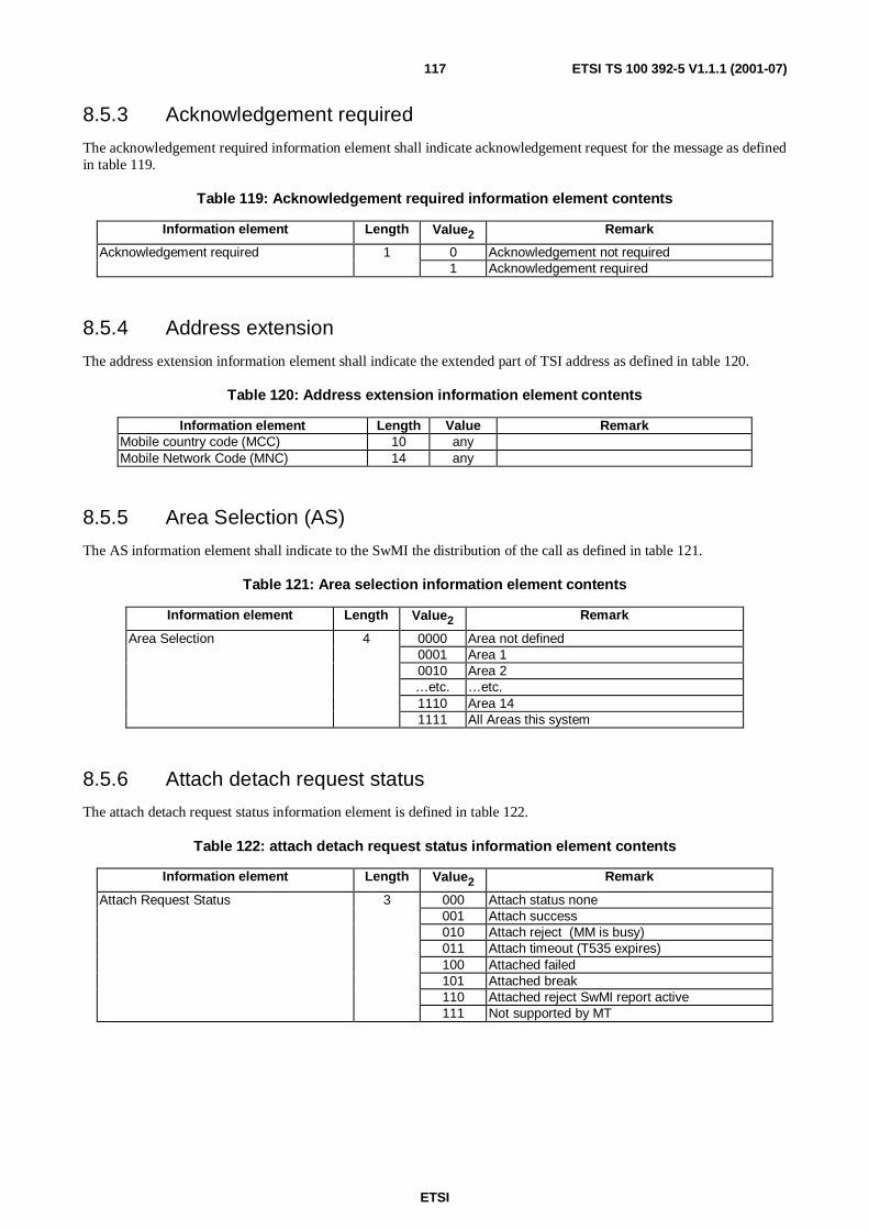
ETSI
ETSI TS 100 392-5 V1.1.1 (2001-07)117
8.5.3 Acknowledgement required
The acknowledgement required information element shall indicate acknowledgement request for the message as definedin table 119.
Table 119: Acknowledgement required information element contents
Information element Length Value2 Remark
Acknowledgement required 1 0 Acknowledgement not required1 Acknowledgement required
8.5.4 Address extension
The address extension information element shall indicate the extended part of TSI address as defined in table 120.
Table 120: Address extension information element contents
Information element Length Value RemarkMobile country code (MCC) 10 anyMobile Network Code (MNC) 14 any
8.5.5 Area Selection (AS)
The AS information element shall indicate to the SwMI the distribution of the call as defined in table 121.
Table 121: Area selection information element contents
Information element Length Value2 Remark
Area Selection 4 0000 Area not defined0001 Area 10010 Area 2…etc. …etc.1110 Area 141111 All Areas this system
8.5.6 Attach detach request status
The attach detach request status information element is defined in table 122.
Table 122: attach detach request status information element contents
Information element Length Value2 Remark
000 Attach status none001 Attach success010 Attach reject (MM is busy)011 Attach timeout (T535 expires)100 Attached failed101 Attached break110 Attached reject SwMI report active
Attach Request Status 3
111 Not supported by MT

ETSI
ETSI TS 100 392-5 V1.1.1 (2001-07)118
8.5.7 Basic service information
The basic service information element shall inform the SwMI what basic service is requested as defined in table 123.The total element length of the information element is 8 bits.
Table 123: Basic service information element contents
Information sub-element Length Value2 Remark
Circuit mode type 3 000 Speech: TCH/Snote 1 001 Unprotected: TCH/7.2
010 Low Protection: TCH/4.8, N = 1011 Low Protection: TCH/4.8, N = 4100 Low Protection: TCH/4.8, N = 8101 High Protection: TCH/2.4, N = 1110 High Protection: TCH/2.4, N = 4111 High Protection: TCH/2.4, N = 8
End to end encryption flag 1 0 Clear Modenote 2 1 End-to-end encryptionCommunication type 2 00 Point-to-point
01 Point-to-multipoint10 Point-to-multipoint Acknowledged11 Broadcast
Slots per frame 2 00 One slotnote 3 01 Two slots
10 Three slots11 Four slots
NOTE 1: Indicates the traffic channel (TCH) type and the interleaving depth N.NOTE 2: Indicates whether the circuit mode speech or circuit mode data is end-to-end encrypted.NOTE 3: Indicates the required bit rate for a circuit mode data call. For TCH/7.2, TCH/4.8 and TCH/2.4 the
resulting bit rate is the TCH bit rate multiplied by the number of slots per frame. (For example, TCH/7.2in four time slots per frame gives a circuit mode data rate of 28,8 kbit/s.) For TCH/S this element shallbe present (set to 0).
8.5.8 Battery charge
The battery charge information element shall indicate the charging state of the MT2 battery as defined in table 124.
Table 124: Battery Charge information element contents
Information element Length Value RemarkBattery charge 8 0 Empty
…etc. …etc.100 Full
8.5.9 Bit error ratio
The bit error ratio information element shall indicate the bit error ratio detected by the MT2 in the AI as defined intable 125.
Table 125: Bit Error Ratio information element contents
Information element Length Value RemarkBit error ratio 8 0 BER < 0,01 %
1 0,01 % to less than 0,1 %2 0,1 % to less than 0,5 %3 0,5 % to less than 1,0 %4 1,0 % to less than 2,0%5 2,0 % to less than 4,0 %6 4,0 % to less than 8,0 %7 ≥ 8,0 %
99 Not known or detectable

ETSI
ETSI TS 100 392-5 V1.1.1 (2001-07)119
8.5.10 BS service details
The BS service details information element includes the parameters included in the BS service details - seeclause 18.5.2 in EN 300 392-2, as defined in table 126.
Table 126: BS service details information element
Information sub-element Length Value Remark0 Registration not required on this cellRegistration 11 Registration mandatory on this cell0 De-registration not required on this cellDe-registration 11 De-registration mandatory on this cell0 Cell is not a priority cellPriority cell 11 Cell is a priority cell0 Cell may use minimum modeMinimum mode service 11 Cell never uses minimum mode0 Migration is not supported by this cellMigration 11 Migration is supported by this cell0 System wide services temporarily not supportedSystem wide services 11 Normal mode0 TETRA voice service is not supported on this cellTETRA voice service 11 TETRA voice service is supported on this cell0 Circuit mode data service is not supported on this cellCircuit mode data service 11 Circuit mode data service is supported on this cell0 Default valueReserved 11 Reserved for future expansion0 SNDCP service is not available on this cellNDCP Service 11 SNDCP service is available on this cell0 Air interface encryption is not available on this cellAir interface encryption
Service1
1 Air interface encryption is available on this cell0 Advanced link is not supported on this cellAdvanced link supported 11 Advanced link is supported on this cell
8.5.11 Call amalgamation
The call amalgamation information element is as defined in table 127.
Table 127: Call amalgamation information element contents
Information element Length Value RemarkCall amalgamation 1 0 Call not amalgamated
1 Call amalgamated
8.5.12 Call handle
The call handle information element shall be used to distinguish between multiple or concurrent service instances asdefined in table 128.
Table 128: Call handle information element contents
Information element Length Value RemarkCall handle 16 0 Dummy call handle
1- 216-1 Call instance label
NOTE: This information element is not used on the air interface, although there is an equivalent informationelement "call identity".

ETSI
ETSI TS 100 392-5 V1.1.1 (2001-07)120
8.5.13 Called party extension
The called party extension information element shall indicate to the SwMI the extended part of the TSI address of thecalled user as defined in table 129.
Table 129: Called party extension information element contents
Information element Length Value RemarkCountry Code 10 any See ETS 300 392-1 [1] clause 7Network Code 14 any See ETS 300 392-1 [1] clause 7
8.5.14 Called party self address type
The called party self address type information element shall indicate the address, which is followed in the PDU asdefined in table 130.
Table 130: Called Party self address type information element contents
Information element Length Value2 Remark
Called party self address type 2 00 Reserved01 Individual address10 Group address11 Broadcast
8.5.15 Called party short number address (SNA)
The called party short number address information element shall indicate to the SwMI the Short Number address (SNA)of the called user as defined in table 131.
Table 131: Called party short number address information element contents
Information element Length2 Value Remark
Called party short number address 8 0-255 See ETS 300 392-12-7 [20]
8.5.16 Called party Short Subscriber Identity (SSI)
The called party short subscriber identity information element shall indicate to the SwMI the Short Subscriber Identity(SSI) address of the called user as defined in table 132.
Table 132: Called party short subscriber identity information element contents
Information element Length Value RemarkShort subscriber identity 24 any See ETS 300 392-1 [1] clause 7

ETSI
ETSI TS 100 392-5 V1.1.1 (2001-07)121
8.5.17 Called party type identifier
The called party type identifier information element shall indicate the type of address, which shall follow in the PDU asdefined in table 133.
Table 133: Called party type identifier information element contents
Information element Length Value2 Remark
Called party type identifier 3 000 Short Number Address (SNA)001 Short Subscriber Identity (SSI)010 Tetra Subscriber Identity (TSI = MNI+SSI)011 Reserved100 MT2 external subscriber number default gateway
address
8.5.18 Calling party extension
The calling party extension information element shall indicate the extended part of the TSI address of the calling user asdefined in table 134.
Table 134: Calling party extension information element contents
Information element Length Value RemarkCountry Code 10 any See ETS 300 392-1 [1] clause 7Network Code 14 any See ETS 300 392-1 [1] clause 7
8.5.19 Calling party Short Subscriber Identity (SSI)
The calling party short subscriber identity information element shall indicate the Short Subscriber Identity (SSI) addressof the calling user as defined in table 135.
Table 135: Calling party short subscriber identity information element contents
Information element Length Value RemarkShort subscriber identity 24 any See ETS 300 392-1 [1] clause 7
8.5.20 Calling party type identifier
The calling party type identifier information element coding shall indicate the type of address, which shall follow in thePDU as defined in table 136.
Table 136: Calling Party Type Identifier information element contents
Information element Length Value RemarkCalling party type identifier 2 0 Reserved
1 Short Subscriber Identity (SSI)2 Tetra Subscriber Identity (TSI = MNI + SSI)3 None

ETSI
ETSI TS 100 392-5 V1.1.1 (2001-07)122
8.5.21 Call ownership
The call ownership information element in group call shall indicate to the MS whether it is capable to disconnect thecall or not as defined in table 137. In individual call it shall indicate to both parties whether the call set up is for anormal or amalgamated call.
Table 137: Call ownership information element contents
Information element Length Value2 Remark
Call ownership 1 0 Not a call owner (Group call)Normal call set up (Individual call)
1 A call owner (Group call)Amalgamated call (Individual call)
8.5.22 Call priority
The call priority information element shall inform the SwMI or the MS/LS about the call priority as defined intable 138.
Table 138: Call priority information element contents
Information element Length Value2 Remark
Call priority 4 0000 Priority not defined0001 Priority 1 (Lowest priority)0010 Priority 2…etc. …etc.1011 Priority 111100 Pre-emptive priority 11101 Pre-emptive priority 21110 Pre-emptive priority 31111 Pre-emptive priority 4 (Emergency)
8.5.23 Call queued
The call queued information element shall inform the calling MS/LS that the call has been put in queue as defined intable 139.
Table 139: Call queued information element contents
Information element Length Value2 Remark
Call queued 1 0 Call is not queued1 Call is queued

ETSI
ETSI TS 100 392-5 V1.1.1 (2001-07)123
8.5.24 Call status
The call status information element shall inform the MS/LS about the status of the call as defined in table 140.
Table 140: Call status information element contents
Information element Length Value2 Remark
Call status 3 000 Call is progressing001 Call is queued010 Requested subscriber is paged011 Call Continue100 Hang time expired101 Reserved110 Reserved111 Reserved
8.5.25 Call time-out
The call time-out information element shall set the maximum call time (T310) as defined in table 141.
Table 141: Call time-out information element contents
Information element Length Value2 Remark
Call time-out 4 0000 Infinite Time0001 30 s0010 45 s0011 60 s0100 2 minutes0101 3 minutes0110 4 minutes0111 5 minutes1000 6 minutes1001 8 minutes1010 10 minutes1011 12 minutes1100 15 minutes1101 20 minutes1110 30 minutes1111 Reserved
8.5.26 Call time-out, set-up phase
The call time-out, set-up phase information element (T301 and T302) shall set the maximum set-up time valid for thecall set up phase as defined in table 142.
Table 142: Call time-out, set-up phase information element contents
Information element Length Value2 Remark
Call time out, set-up phase 3 000 Use predefined value (note)001 1 s010 2 s011 5 s100 10 s101 20 s110 30 s111 60 s
NOTE: This value shall indicate that the MS/LS shall use a predefined value for the timer.

ETSI
ETSI TS 100 392-5 V1.1.1 (2001-07)124
8.5.27 CC profile
The CC profile information element shall define operation of the TNP1 Relay for CC signalling messages as defined intable 143.
Table 143: CC profile information element contents
Information element Length Value Remark0 Speech Voice call control - MT controlledSpeech voice call control 11 Speech Voice call control - TE controlled0 Data Voice call control - MT controlledData voice call control 11 Data Voice call control - TE controlled
8.5.28 Circuit mode and MS services
The circuit mode and MS services information element shall list the circuit mode capabilities of the MT2 as defined intable 144. It shall not give any information of the capabilities of the underlying network. This information element shallcontain sub-elements so that the total length2 is 9 bits, which are encoded into two octets in the PDUs.
Table 144: Circuit mode and MS services information element contents
Information element Length Value2 Remark
TETRA encoded speech 1 0 Not capable1 Capable
7,2 kbit/s unprotected data/speech 1 0 Not capable1 Capable
7,2 kbit/s non-TETRA encoded speech 1 0 Not capable1 Capable
4,8 kbit/s unprotected data/speech, 1 0 Not capableInterleaving depth = 1 1 Capable4,8 kbit/s unprotected data/speech, 1 0 Not capableInterleaving depth = 4 1 Capable4,8 kbit/s unprotected data/speech, 1 0 Not capableInterleaving depth = 8 1 Capable2,4 kbit/s unprotected data/speech, 1 0 Not capableInterleaving depth = 1 1 Capable2,4 kbit/s unprotected data/speech, 1 0 Not capableInterleaving depth = 4 1 Capable2,4 kbit/s unprotected data/speech, 1 0 Not capableInterleaving depth = 8 1 CapableFrequency simplex/duplex 1 0 Frequency simplex supported
1 Frequency duplex and simplex supportedSingle/multislot 1 0 Single slot supported
1 Multislot and single slot supportedConcurrent multicarrier operation 1 0 Single carrier operation supported
1 Multi and single carrier operationsupported
Fast switching MS 1 0 Fast switching not supported1 Fast switching supported
DCK air interface encryption 1 0 DCK air interface encryption notsupported
1 DCK air interface encryption supportedCLCH needed on carrier change 1 0 No CLCH needed on carrier change
1 CLCH needed on carrier changeConcurrent channels 1 0 Concurrent channels not supported(Concurrent services) 1 Concurrent channels supportedAdvanced link 1 0 Advanced link not supported
1 Advanced link supportedMinimum mode 1 0 Minimum mode not supported
1 Minimum mode supported
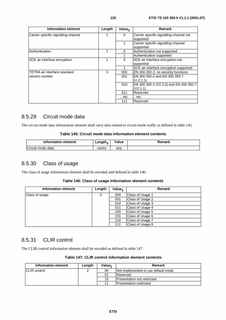
ETSI
ETSI TS 100 392-5 V1.1.1 (2001-07)125
Information element Length Value2 Remark
Carrier specific signalling channel 1 0 Carrier specific signalling channel notsupported
1 Carrier specific signalling channelsupported
Authentication 1 0 Authentication not supported1 Authentication supported
SCK air interface encryption 1 0 SCK air interface encryption notsupported
1 SCK air interface encryption supportedTETRA air interface standard 3 000 EN 300 392-2, no security functionsversion number 001 EN 300 392-2 and EN 300 392-7
(V.2.1.1)010 EN 300 392-2 (V2.3.2) and EN 300 392-7
(V2.1.1)011 Reserved
...etc. ...etc.111 Reserved
8.5.29 Circuit mode data
The circuit mode data information element shall carry data related to circuit mode traffic as defined in table 145.
Table 145: Circuit mode data information element contents
Information element Length2 Value Remark
Circuit mode data varies any
8.5.30 Class of usage
The class of usage information element shall be encoded and defined in table 146.
Table 146: Class of usage information element contents
Information element Length Value2 Remark
Class of usage 3 000 Class of Usage 1001 Class of Usage 2010 Class of Usage 3011 Class of Usage 4100 Class of Usage 5101 Class of Usage 6110 Class of Usage 7111 Class of Usage 8
8.5.31 CLIR control
The CLIR control information element shall be encoded as defined in table 147.
Table 147: CLIR control information element contents
Information element Length Value2 Remark
CLIR control 2 00 Not implemented or use default mode01 Reserved10 Presentation not restricted11 Presentation restricted
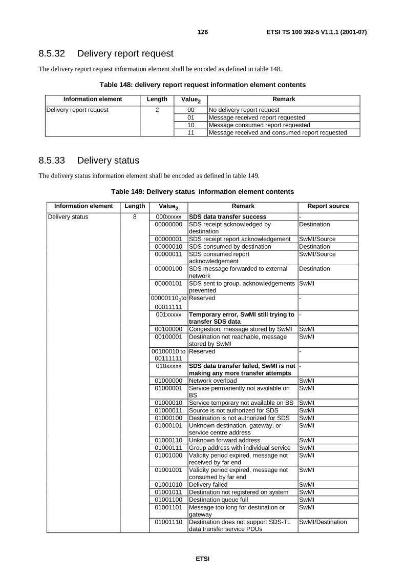
ETSI
ETSI TS 100 392-5 V1.1.1 (2001-07)126
8.5.32 Delivery report request
The delivery report request information element shall be encoded as defined in table 148.
Table 148: delivery report request information element contents
Information element Length Value2 Remark
Delivery report request 2 00 No delivery report request01 Message received report requested10 Message consumed report requested11 Message received and consumed report requested
8.5.33 Delivery status
The delivery status information element shall be encoded as defined in table 149.
Table 149: Delivery status information element contents
Information element Length Value2 Remark Report source
Delivery status 8 000xxxxx SDS data transfer success -00000000 SDS receipt acknowledged by
destinationDestination
00000001 SDS receipt report acknowledgement SwMI/Source00000010 SDS consumed by destination Destination00000011 SDS consumed report
acknowledgementSwMI/Source
00000100 SDS message forwarded to externalnetwork
Destination
00000101 SDS sent to group, acknowledgementsprevented
SwMI
000001102to
00011111
Reserved -
001xxxxx Temporary error, SwMI still trying totransfer SDS data
-
00100000 Congestion, message stored by SwMI SwMI00100001 Destination not reachable, message
stored by SwMISwMI
00100010 to00111111
Reserved -
010xxxxx SDS data transfer failed, SwMI is notmaking any more transfer attempts
-
01000000 Network overload SwMI01000001 Service permanently not available on
BSSwMI
01000010 Service temporary not available on BS SwMI01000011 Source is not authorized for SDS SwMI01000100 Destination is not authorized for SDS SwMI01000101 Unknown destination, gateway, or
service centre addressSwMI
01000110 Unknown forward address SwMI01000111 Group address with individual service SwMI01001000 Validity period expired, message not
received by far endSwMI
01001001 Validity period expired, message notconsumed by far end
SwMI
01001010 Delivery failed SwMI01001011 Destination not registered on system SwMI01001100 Destination queue full SwMI01001101 Message too long for destination or
gatewaySwMI
01001110 Destination does not support SDS-TLdata transfer service PDUs
SwMI/Destination

ETSI
ETSI TS 100 392-5 V1.1.1 (2001-07)127
Information element Length Value2 Remark Report source
01001111 Destination host not connected Destination01010000 Protocol not supported Destination01010001 Data coding scheme not supported Destination01010010 Destination memory full, message
discardedDestination
01010011 Destination not accepting SDSmessages
SwMI
01010100 Reserved -01010101 Reserved -01010110 Destination address administratively
prohibitedSwMI
01010111 Can not route to external network SwMI01011000 Unknown external subscriber number SwMI01011001 Negative report acknowledgement Source
01011010 to01011111
Reserved -
011xxxxx Flow control messages -01100000 Destination memory full Destination01100001 Destination memory available Destination01100010 Start pending messages Destination01100011 No pending messages SwMI
01100100 to01111111
Reserved -
100xxxxx End to end control messages -10000000 Stop sending Destination10000001 Start sending Destination
10000010 to10011111
Available for user application definition,note
Destination
101xxxxx to111xxxxx
Reserved for future use -
NOTE: These values should be co-ordinated outside the scope of the present document in order to preventclashed.
8.5.34 Direct mode
The direct mode information element shall be encoded as defined in table 150.
Table 150: Direct mode information element contents
Information element Length Value RemarkDirect mode 1 1 Start of direct mode operation
8.5.35 Disconnect type
The disconnect type information element shall be encoded as defined in table 151.
Table 151: Disconnect type information element contents
Information element Length Value RemarkDisconnect type 2 00 Disconnect call
01 Leave call without disconnection10 Leave call temporarily11 Reserved
8.5.36 DTMF result
The DTMF information element shall be encoded as defined in table 152.

ETSI
ETSI TS 100 392-5 V1.1.1 (2001-07)128
Table 152: DTMF Result element contents
Information element Length Value RemarkDTMF Result 1 0 DTMF not supported
1 DTMF not subscribed
8.5.37 Disconnect cause
The disconnect cause information element shall inform the MS/LS or the infrastructure of the reason for therelease/disconnection as defined in table 153.
Table 153: Disconnect cause information element contents
Information element Length Value2 Remark
Disconnect cause 5 00000 Cause not defined or unknown00001 User requested disconnect00010 Called party busy00011 Called party not reachable00100 Called party does not support encryption00101 Congestion in infrastructure00110 Not allowed traffic case00111 Incompatible traffic case01000 Requested service not available01001 Pre-emptive use of resource01010 Invalid Call Identifier01011 Call Rejected by the called party01100 No idle CC entity01101 Expiry of timer01110 SwMI requested Disconnection01111 Acknowledged Service not completed10000 Reserved…etc. …etc.11111 Reserved
8.5.38 Disconnect status
The disconnect status information element shall be encoded as defined in table 154.
Table 154: Disconnect status information element contents
Information element Length Value RemarkDisconnect status 2 00 Disconnect successful
01 Disconnect unsuccessful, the release is releasedfrom the call
10 Disconnection unsuccessful, not the call owner,the user is released from the call
11 The user is released from the call

ETSI
ETSI TS 100 392-5 V1.1.1 (2001-07)129
8.5.39 DTMF digits
The DTMF information element shall allow the transfer of DTMF digits (n digits where n shall be less than or equalto 255) to another user application. Each digit shall be encoded as defined in table 155.
Table 155: DTMF information element contents
Information element Length Value2 Remark
DTMF digit 4 0000 Digit "0"0001 Digit "1"0010 Digit "2"0011 Digit "3"0100 Digit "4"0101 Digit "5"0110 Digit "6"0111 Digit "7"1000 Digit "8"1001 Digit "9"1010 Digit "*"1011 Digit "#"1100 Digit "A"1101 Digit "B"1110 Digit "C"1111 Digit "D"
8.5.40 DTMF tone delimiter
The DTMF tone delimiter information element is defined in table 156.
Table156: DTMF tone delimiter information element contents
Information element Length Value RemarkDTMF tone delimiter 1 0 DTMF tone start
1 DTMF tone end
8.5.41 Dual watch
The dual watch information element is defined in table 157.
Table 157: Dual Watch information element contents
Information element Length Value2 Remark
Dual watch 4 0000 Starting dual watch mode0001 Modify or resume dual watch mode0010 Dual watch mode accepted0011 Dual watch mode rejected0100 Dual watch mode not supported0101 Terminating dual watch mode0110 Terminating dual watch mode response0111 Dual watch energy economy group changed by SwMI1000 Dual watch mode terminated by SwMI

ETSI
ETSI TS 100 392-5 V1.1.1 (2001-07)130
8.5.42 Enable/Disable status
The Enable/disable status information element shall indicate which of the enable/disable status types (i.e. temporary orpermanent) for TEI or equipment is requested as defined in table 158.
Table 158: Enable/disable status information element contents
Information element Length Value RemarkEnable/disable status 2 0 Enabled
1 Temporary disabled2 Permanent disabled3 Not used
8.5.43 End to end encryption flag
The end-to-end encryption flag information element shall indicate/request for end-to-end encryption, as defined intable 159.
Table 159: End-to-end encryption flag information element contents
Information element Length Value Remark0 ClearEnd to end encryption flag 11 End to End encrypted
8.5.44 Energy economy mode
The energy economy mode information element shall be used to indicate which energy saving scheme is requested (ifany) as defined in table 160.
Table 160: Energy economy mode information element contents
Information element Length Value2 Remark
Energy economy mode 3 000 Stay alive001 Economy mode 1 (EG1)010 Economy mode 2 (EG2)011 Economy mode 3 (EG3)100 Economy mode 4 (EG4)101 Economy mode 5 (EG5)110 Economy mode 6 (EG6)111 Economy mode 7 (EG7)
8.5.45 Energy economy mode status
The energy economy mode status information element shall be encoded as defined in table 161.
Table 161: Energy economy mode status information element contents
Information element Length Value RemarkEnergy economy mode status 1 0 Accepted
1 Rejected

ETSI
ETSI TS 100 392-5 V1.1.1 (2001-07)131
8.5.46 External subscriber number
The external subscriber number information element is a structure with two fields. First a length element, second the listof digits. The external subscriber number information element shall be encoded as described in table 162.
Table 162: External subscriber number information element contents
Information element Length RemarkNumber of digits 8 note 2, note 3External subscriber number digit note 1NOTE 1: This information element shall be repeated according to the number of digits.NOTE 2: The number of digits will be 0 if no external number is present.NOTE 3: When building the PDUs, if the number of digits is odd then the value 11112 will be appended to the
end of the string of digits.
8.5.47 External subscriber number digits
Each digit in the external subscriber number information element shall be as defined in table 163.
Table 163: External subscriber digit information element contents
Information element Length Value2 Remark
External subscriber number digit 4 0000 Digit "0"0001 Digit "1"0010 Digit "2"0011 Digit "3"0100 Digit "4"0101 Digit "5"0110 Digit "6"0111 Digit "7"1000 Digit "8"1001 Digit "9"1010 Digit "*"1011 Digit "#"1100 Digit "+"1101 Reserved1110 Reserved1111 Reserved
8.5.48 Facility
The facility information element is an optional variable length information element and shall be used to send andreceive SS information appended to the PDUs, which can carry the facility information element.
The size and the structure of the facility information element are dependent on each individual SS and shall be furtherdetailed in the SS protocol clauses.
There can be multiple facility information elements in the same PDU.
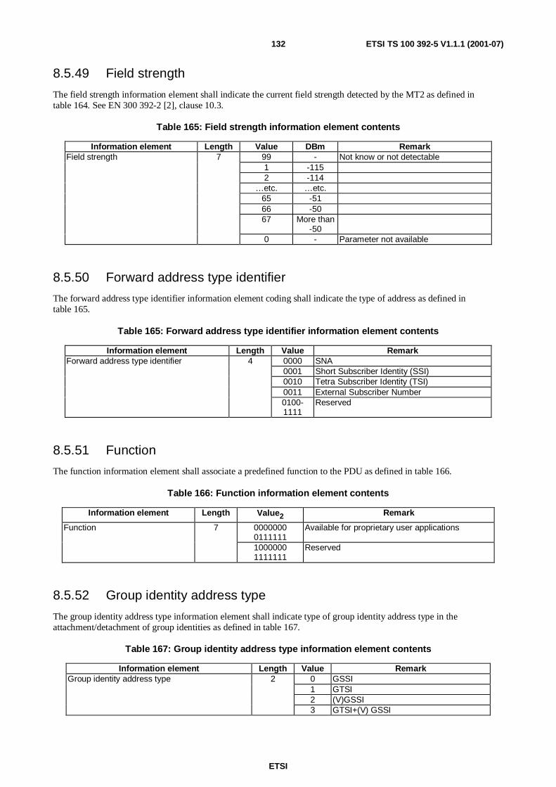
ETSI
ETSI TS 100 392-5 V1.1.1 (2001-07)132
8.5.49 Field strength
The field strength information element shall indicate the current field strength detected by the MT2 as defined intable 164. See EN 300 392-2 [2], clause 10.3.
Table 165: Field strength information element contents
Information element Length Value DBm RemarkField strength 7 99 - Not know or not detectable
1 -1152 -114
…etc. …etc.65 -5166 -5067 More than
-500 - Parameter not available
8.5.50 Forward address type identifier
The forward address type identifier information element coding shall indicate the type of address as defined intable 165.
Table 165: Forward address type identifier information element contents
Information element Length Value RemarkForward address type identifier 4 0000 SNA
0001 Short Subscriber Identity (SSI)0010 Tetra Subscriber Identity (TSI)0011 External Subscriber Number0100-1111
Reserved
8.5.51 Function
The function information element shall associate a predefined function to the PDU as defined in table 166.
Table 166: Function information element contents
Information element Length Value2 Remark
Function 7 00000000111111
Available for proprietary user applications
10000001111111
Reserved
8.5.52 Group identity address type
The group identity address type information element shall indicate type of group identity address type in theattachment/detachment of group identities as defined in table 167.
Table 167: Group identity address type information element contents
Information element Length Value RemarkGroup identity address type 2 0 GSSI
1 GTSI2 (V)GSSI3 GTSI+(V) GSSI

ETSI
ETSI TS 100 392-5 V1.1.1 (2001-07)133
8.5.53 Group identity attach/detach mode
The group identity attach/detach mode information element shall indicate the mode of the attachment/detachment ofgroup identities as defined in table 168.
Table 168: Group identity attach/detach mode information element contents
Information element Length Value RemarkGroup Identity Attach/Detach Mode 1 0 Amendment
1 Detach all currently active group identities andattach group identities defined in the groupidentity (downlink/uplink) element (if any)
8.5.54 Group identity attach/detach type identifier
The group identity attach/detach type identifier information element shall be encoded as defined in table 169.
Table 169: Group identity attach/detach type identifier information element contents
Information element Length Value RemarkGroup identity attach/detach type identifier 1 0 Attached
1 Detached
8.5.55 Group identity attachment
The group identity attachment information element shall be encoded as defined in table 170.
Table 170: Group identity attachment information element contents
Information element Length Value RemarkGroup identity attachment lifetime 2 anyClass of usage 3 any
8.5.56 Group identity attachment lifetime
The group identity attachment lifetime information element shall indicate a lifetime of the attachment of the groupidentity defined by the infrastructure for a MS as defined in table 171.
Table 171: Group identity attachment lifetime < information element contents
Information element Length Value RemarkGroup identity attachment lifetime 2 00 Attachment not needed
01 Attachment for next ITSI attach required10 Attachment not allowed for next ITSI attach11 Attachment for next location update required

ETSI
ETSI TS 100 392-5 V1.1.1 (2001-07)134
8.5.57 Group identity detachment downlink
The group identity detachment information element shall indicate the infrastructure detachment reasons as defined intable 172.
Table 172: Group identity detachment downlink information element contents
Information element Length Value2 Remark
Group identity detachment downlink 2 00 Unknown group identity (note)01 Temporary 1 detachment (note)10 Temporary 2 detachment (note)11 Permanent detachment (note)
NOTE: All these values are network dependent.
8.5.58 Group identity detachment uplink
The group identity detachment uplink information element shall indicate the MS detachment reasons as defined intable 173.
Table 173: Group identity detachment uplink information element contents
Information element Length Value RemarkGroup identity detachment uplink 2 0 Unknown group identity
1 No valid encryption key (end-to-end)2 User initiated3 Capacity exceeded
8.5.59 Group identity downlink
The group identity downlink information element shall be used to join the parameters for a group identityattachment/detachment used by the infrastructure as defined in table 174.
Table 174: Group identity downlink information element contents
Information element Length Value Type C/O/M RemarkGroup identity attach/detach type identifier 1 any 1 MGroup identity attachment 5 any C note 1Group identity detachment downlink 2 any C note 1Group identity address type 2 any MGSSI 24 any C note 2Address extension 24 any C note 2NOTE 1: Shall be conditional on the value of Group Identity Attach/Detach Type Identifier (GIADTI):
- GIADTI = 0; Group Identity Attachment;- GIADTI = 1; Group Identity Detachment Downlink.
NOTE 2: Shall be conditional on the value of Group Identity Address Type (GIAT):- GIAT = 0; GSSI;- GIAT = 1; GSSI + Address Extension (GTSI).
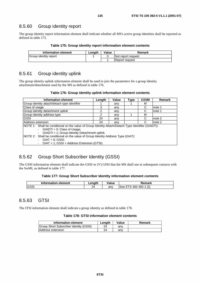
ETSI
ETSI TS 100 392-5 V1.1.1 (2001-07)135
8.5.60 Group identity report
The group identity report information element shall indicate whether all MS's active group identities shall be reported asdefined in table 175.
Table 175: Group identity report information element contents
Information element Length Value RemarkGroup identity report 1 0 Not report request
1 Report request
8.5.61 Group identity uplink
The group identity uplink information element shall be used to join the parameters for a group identityattachment/detachment used by the MS as defined in table 176.
Table 176: Group identity uplink information element contents
Information element Length Value Type C/O/M RemarkGroup identity attach/detach type identifier 1 any 1 MClass of usage 3 any C note 1Group identity detachment uplink 2 any C note 1Group identity address type 2 any 1 MGSSI 24 any C note 2Address extension 24 any C note 2NOTE 1: Shall be conditional on the value of Group Identity Attach/Detach Type Identifier (GIADTI):
- GIADTI = 0; Class of Usage;- GIADTI = 1; Group Identity Detachment uplink.
NOTE 2: Shall be conditional on the value of Group Identity Address Type (GIAT):- GIAT = 0; GSSI;- GIAT = 1; GSSI + Address Extension (GTSI).
8.5.62 Group Short Subscriber Identity (GSSI)
The GSSI information element shall indicate the GSSI or (V) GSSI that the MS shall use in subsequent contacts withthe SwMI, as defined in table 177.
Table 177: Group Short Subscriber Identity information element contents
Information element Length Value RemarkGSSI 24 any See ETS 300 392-1 [1]
8.5.63 GTSI
The ITSI information element shall indicate a group identity as defined in table 178.
Table 178: GTSI information element contents
Information element Length Value RemarkGroup Short Subscriber Identity (GSSI) 24 anyAddress extension 24 any

ETSI
ETSI TS 100 392-5 V1.1.1 (2001-07)136
8.5.64 Hardware version
The hardware version information element shall inform the TE2 user application about the MT2 hardware version asdefined in table 179. The total number of characters, including line terminators, shall not exceed 128 characters.
Table 179: Hardware version information element contents
Information element Length Value RemarkHardware version n x 8 any 8 bits for each ASCII alphabet character
8.5.65 Hook method selection
The hook method selection information element shall inform the infrastructure and the called user(s) of the preferredhook method as defined in table 180.
Table 180: Hook method selection information element contents
Information element Length Value RemarkHook method selection 1 0 No hook signalling (direct through-connect)
1 Hook on/Hook off signalling
8.5.66 Internal temperature
The internal temperature information element shall indicate the MT2 temperature as defined in table 181
Table 181: Internal temperature information element contents
Information element Length Value Remark0 CelsiusTemperature scale 11 Fahrenheit0 Positive degreeTemperature sign 11 Negative degree
Temperature degree 8 0-255Temperature sub degree 4 0-15 Additional 1/16 degree precisionReserved 2 00 Reserved
EXAMPLE: 1 0 00100101 0001 00 means: Celsius, positive, 37 + 1/16 degrees.
8.5.67 ISO global object ID
The ISO global object ID information element shall inform the TE2 user application about the MT2 identification interms of global ISO definition as defined in table 182. The characters shall be aligned sequentially. The total number ofcharacters, including line terminators, shall not exceed 256 characters.
Table 182: ISO global object ID information element contents
Information element Length Value RemarkISO global object ID n * 8 any 8 bits for each ASCII alphabet character

ETSI
ETSI TS 100 392-5 V1.1.1 (2001-07)137
8.5.68 ITSI
The ITSI information element shall indicate identity of the radio as defined in table 183.
Table 183: ITSI information element contents
Information element Length Value RemarkSSI 24 any ISSI of the MSAddress extension 24 any MNI of the MS
8.5.69 Key Mask
The key mask information element indicates type of keys that shall appear in the request and be checked among SDSstack messages. The key mask can include multiple keys.
Table 184: Key mask information element contents
Information element Length Value2 Remark
Key mask 4 1111 All keys shall appear0001 SDS type0010 Message status0011 SDS type and Message status0100 Reserved…etc. …etc.1110 Reserved
8.5.70 LA
The LA information element shall indicate the area in which a cell is located, either the serving cell or a neighbour cellas define in table 185.
Table 185: Location area information element contents
Information element Length Value RemarkLA 14 any
8.5.71 Length indicator
The length indicator information element shall define the length of the User defined data-4 as defined in table 186.
Table 186: Length indicator information element contents
Information element Length Value RemarkLength indicator 11 0 0 bits
1 1 bitetc. etc.
(211-1) 2 047 bits
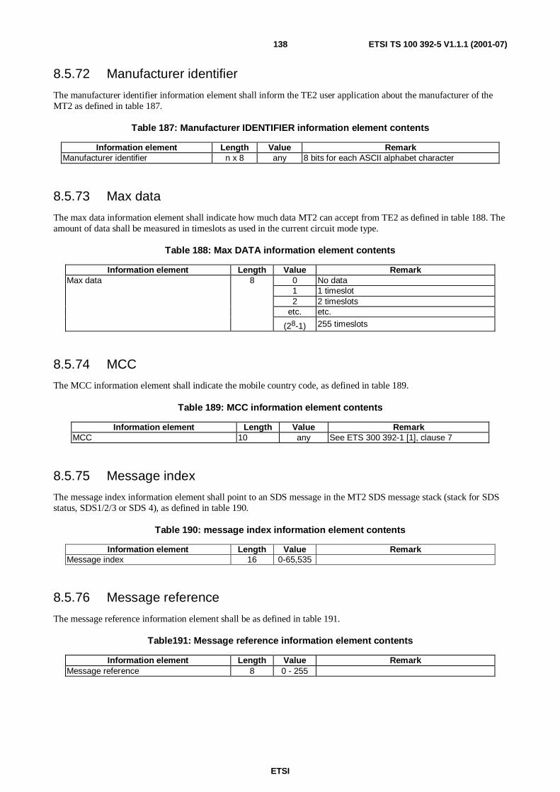
ETSI
ETSI TS 100 392-5 V1.1.1 (2001-07)138
8.5.72 Manufacturer identifier
The manufacturer identifier information element shall inform the TE2 user application about the manufacturer of theMT2 as defined in table 187.
Table 187: Manufacturer IDENTIFIER information element contents
Information element Length Value RemarkManufacturer identifier n x 8 any 8 bits for each ASCII alphabet character
8.5.73 Max data
The max data information element shall indicate how much data MT2 can accept from TE2 as defined in table 188. Theamount of data shall be measured in timeslots as used in the current circuit mode type.
Table 188: Max DATA information element contents
Information element Length Value RemarkMax data 8 0 No data
1 1 timeslot2 2 timeslots
etc. etc.
(28-1) 255 timeslots
8.5.74 MCC
The MCC information element shall indicate the mobile country code, as defined in table 189.
Table 189: MCC information element contents
Information element Length Value RemarkMCC 10 any See ETS 300 392-1 [1], clause 7
8.5.75 Message index
The message index information element shall point to an SDS message in the MT2 SDS message stack (stack for SDSstatus, SDS1/2/3 or SDS 4), as defined in table 190.
Table 190: message index information element contents
Information element Length Value RemarkMessage index 16 0-65,535
8.5.76 Message reference
The message reference information element shall be as defined in table 191.
Table191: Message reference information element contents
Information element Length Value RemarkMessage reference 8 0 - 255

ETSI
ETSI TS 100 392-5 V1.1.1 (2001-07)139
8.5.77 Message reference handle
The message reference handle information element shall be as defined in table 192.
Table 192: Message reference handle information element contents
Information element Length Value RemarkMessage reference handle 8 0 - 25510
8.5.78 Microphone on off
The microphone on off information element shall be as defined in table 193.
Table193: Microphone on off information element contents
Information element Length Value Remark0 Microphone offMicrophone on off 11 Microphone on
8.5.79 MM profile
The MM profile information element shall define operation of the TNP1 Relay for MM signalling messages as definedin table 194.
Table 194: MM profile information element contents
Information element Length Value Remark0 Registration/ De-registration – MT
controlledRegistration/ De-registration control(note)
1
1 Registration/ De-registration – TEcontrolled
0 Security – MT controlledSecurity control (authentication,enable/disable, encryption)(note)
11 Security – TE controlled
0 MM status control – MT controlledMM status control (energy saving, dualwatch)(note)
11 MM status control – TE controlled
0 Group Management – MT controlledGroup management control (groupattach/detach)(note)
11 Group Management –TE controlled
NOTE: All the updates will be sent to both applications (MT and TE).
8.5.80 MM transfer result
The MM transfer result information element shall inform the TE2 user application about the success of the U-ITSIDETACH transfer as defined in table 195.
Table 195: MM transfer result information element contents
Information element Length Value2 Remark
MM transfer result 1 0 Transfer successful done1 Transfer fail
8.5.81 MNC
The MNC information element shall indicate the mobile network code, as defined in table 196.

ETSI
ETSI TS 100 392-5 V1.1.1 (2001-07)140
Table 196 MNC information element contents
Information element Length Value RemarkMNC 14 any See ETS 300 392-1 [1], clause 7
8.5.82 Model
The model information element shall inform the TE2 user application about the MT2 model as defined in table 197.
Table 197: Model information element contents
Information element Length Value RemarkModel n * 8 any 8 bits for each ASCII alphabet character
8.5.83 Modify
The modify information element shall be used to change an ongoing call either to a new basic service or the behaviourfrom simplex to duplex or reverse as defined in table 198.
Table 198: Modify information element contents
Information element Length Value RemarkSimplex/Duplex selection 1 any See description of the Simplex/Duplex selection"
information elementBasic service information 8 any See description of the basic service information
element
8.5.84 More information flag
The more information flag information element shall be used to indicate to the application that there are more messagesas defined in table 199. If this flag is set to "more information" the TE shall not send any more commands until allrelated data has been returned by the MT (flag set to "no more information").
Table 199: More information flag information element contents
Information element Length Value Remark0 No more informationMore information flag 11 More information
8.5.85 MT2 default gateway address
The MT2 default gateway address information element shall be encoded as defined in table 200.
Table 200: MT2 gateway default address information element contents
Information element Length Value Type C/O/M RemarkAddress type identifier 2 any 1 MSSI 24 any C noteAddress extension 24 any C noteNOTE: Shall be conditional on the value of Address Type Identifier (ATI):
- ATI = 1; SSI;- ATI = 2; SSI + Address Extension.

ETSI
ETSI TS 100 392-5 V1.1.1 (2001-07)141
8.5.86 Notification indicator
The notification indicator information element shall be used in SSs by the SwMI to inform a MS/LS of various eventsas presented in table 201 and defined in ETS 300 392-9 [15] clause 7.2.
Table 201: Notification indicator information element contents
Information element Length Value RemarkNotification indicator 6 0-63 See ETS 300 392-9 [15]
8.5.87 Number of groups
The number of groups information element shall indicate the number of uplink or downlink groups identity as definedin table 202.
Table 202: Number of groups information element contents
Information element Length Value RemarkNumber of groups 4 0-15
8.5.88 Number of messages
The number of messages information element shall be used for repeatable sub elements, as defined in table 203.
Table 203: Number of messages information element contents
Information element Length Value Remark0-254Number of messages 8255 All messages
8.5.89 Over temperature indication
The MTE over temperature indication information element shall be as defined in table 204.
Table 204: Over temperature indication information element contents
Information element Length Value RemarkOver temperature indication 1 0 Normal temperature
1 Over temperature
8.5.90 Packet data mode services
The data mode services information element shall list the packet data mode capabilities of the MT2. It shall not give anyinformation of the capabilities of the underlying network as defined in table 205.
Table 205: Packet data mode services information element contents
Information element Length Value RemarkIpv4 1 0 Not capable
1 CapableIpv6 1 0 Not capable
1 CapableReserved 1 0 Not capable
1 CapableReserved 1 0 Not capable
1 Capable

ETSI
ETSI TS 100 392-5 V1.1.1 (2001-07)142
8.5.91 PDU type
The PDU type information element shall identify the type of TNP1 PDU sent over the PEI as defined in table 206 andtable 207.
Table 206: PDU type information element contents
Information element Length Value Type C/O/M RemarkPDU Group ID 8 any 1 MPDU ID 8 any 1 M
8.5.92 PDU type values
The PDU type values information element shall be encoded as defined in table 207. All the unused group ID and PDUID values are reserved.
Table 207: PDU type values information element contents
Group ID Group IDvalue2
PDU Name PDU IDvalue2
TECC-ALERT IND 00000001TECC-COMPLETE CON 00000010TECC-COMPLETE IND 00000011TECC-COMPLETE REQ 00000100TECC-DTMF IND 00000101TECC-DTMF REQ 00000110TECC-MODIFY IND 00000111TECC-MODIFY REQ 00001000TECC-NOTIFY IND 00001001TECC-PROCEED IND 00001010TECC-RELEASE CON 00001011TECC-RELEASE IND 00001100TECC-RELEASE REQ 00001101TECC-SETUP CON 00001110TECC-SETUP IND 00001111TECC-SETUP REQ 00010000TECC-SETUP RES 00010001TECC-TX CON 00010010TECC-TX IND 00010011
CC 00001001
TECC-TX REQ 00010100TESS-FACILITY CON 00000000TESS-FACILITY IND 00000001TESS-FACILITY REQ 00000010
SS 00001011
TESS-FACILITY RES 00000011TESDS-REPORT IND 00000000TESDS-STATUS IND 00000001TESDS-STATUS REQ 00000010TESDS-UNITDATA IND 00000011
SDS
TESDS-UNITDATA REQ 00000100TESDS-TL-ACK IND 00001011TESDS-TL-ACK REQ 00001100TESDS-TL-REPORT IND 00001101TESDS-TL-REPORT REQ 00001110TESDS-TL-TNSDS-REPORT IND 00001111TESDS-TL-TRANSFER IND 00010000TESDS-TL-TRANSFER REQ 00010001TESDS-TL-UNITDATA IND 00010010
SDS-TL
00001111
TESDS-TL-UNITDATA REQ 00010011

ETSI
ETSI TS 100 392-5 V1.1.1 (2001-07)143
Group ID Group IDvalue2
PDU Name PDU IDvalue2
MM 00010001 TEMM-ATTACH DETACH GROUP IDENTITY CON 00000000TEMM-ATTACH DETACH GROUP IDENTITY IND 00000001TEMM-ATTACH DETACH GROUP IDENTITY REQ 00000010TEMM-ENERGY SAVING CON 00000100TEMM-ENERGY SAVING REQ 00000101TEMM-ENERGY SAVING IND 00000110TEMM-REPORT IND 00000111TEMM-REGISTRATION CON 00001000TEMM-REGISTRATION IND 00001001TEMM-REGISTRATION REQ 00001010TEMM-DEREGISTRATION REQ 00001011TEMM-SERVICE IND 00001100TEMM-DISABLING IND 00001101TEMM-ENABLING IND 00001110TEMAC-FLOW CONTROL 00000000Circuit mode
traffic related00010011
TEMAC-UNITDATA 00000001TEMTA-IDENTIFICATION RESP 00000001TEMTA-IDENTIFICATION REQ 00000010TEMTA-SERVICES CAPABILITY RESP 00000011TEMTA-SERVICES CAPABILITY REQ 00000100TEMTA-SDS-TL CAPABILITY RESP 00000101TEMTA-SDS-TL CAPABILITY REQ 00000110TEMTA-SDS DELETE MESSAGES REQ 00000111TEMTA-SDS MESSAGE ERROR 00001000TEMTA-SDS MESSAGE IND 00001001TEMTA-SDS GET LIST MESSAGES BY KEY REQ 00001010TEMTA-SDS LIST MESSAGES REPLY 00001011TEMTA-SDS NOTIFICATION 00001100TEMTA-SDS SERVICE PROFILE RESP 00001110TEMTA-SDS SERVICE PROFILE SET 00001111TEMTA-SDS SERVICE PROFILE REQ 00010000TEMTA-CC SERVICE PROFILE RESP 00010001TEMTA-CC SERVICE PROFILE SET 00010010TEMTA-CC SERVICE PROFILE REQ 00010011TEMTA-MM SERVICE PROFILE RESP 00010100TEMTA-MM SERVICE PROFILE SET 00010101TEMTA-MM SERVICE PROFILE REQ 00010110TEMTA-SDS-TL SERVICE PROFILE RESP 00010111TEMTA-SDS-TL SERVICE PROFILE SET 00011000TEMTA-SDS-TL SERVICE PROFILE REQ 00011001TEMTA-STATE RESP 00011101TEMTA-STATE REQ 00011110TEMTA-SYSINFO RESP 00011111TEMTA-SYSINFO REQ 00100000TEMTA-IDENTITIES RESP 00100001TEMTA-IDENTITIES REQ 00100010TEMTA-REPORT IND 00100011TEMTA-SPEAKER-MIC REQ 00100101
MT2 userapplicationPDUs
00010100
TEMTA-SETVOLUME REQ 00100110

ETSI
ETSI TS 100 392-5 V1.1.1 (2001-07)144
8.5.93 Poll request
This poll request information element shall be used by the SwMI to request a poll response back from the MS/LS whenan acknowledged group call has been initiated as defined in table 208.
Table 208: Poll request information element contents
Information element Length Value RemarkPoll request 1 0 No poll answer requested
1 Poll answer requested
8.5.94 Poll response
This poll response information element shall be used by the MS/LS to respond to a poll request in an acknowledgedgroup call from the SwMI as defined in table 209.
Table 209: Poll response information element contents
Information element Length Value RemarkPoll response 1 0 No Poll response
1 Poll response
8.5.95 Poll response addresses
The poll response addresses information element shall provide the addresses on responding group members in anacknowledged group call as defined in table 210.
Table 210: Poll response addresses information element contents
Information element Length Value Remark1st TSI address 48 any For TSI address definition see [11] clause 72nd TSI address 48 any…etc. …etc. anyNth TSI address 48 any
8.5.96 Poll response number
The poll response number information element shall provide the number of responding group members in anacknowledged group call as defined in table 211.
Table 211: Poll response number information element contents
Information element Length Value RemarkNumber of responding group members 6 0-63

ETSI
ETSI TS 100 392-5 V1.1.1 (2001-07)145
8.5.97 Poll response percentage
The poll response percentage information element shall provide the percentage of responding group members in anacknowledged group call as defined in table 212.
Table 212: Poll response percentage information element contents
Information element Length Value RemarkPercentage of responding number 6 0 0 %of group members 1 2 %
…etc. …etc.50 100 %51 Reserved
…etc. …etc.63 Reserved
8.5.98 Preferred LA list
The preferred LA list information element shall define the list of the preferred location areas used for cell selection asdefined in table 213.
Table 213: Preferred LA list information element contents
Information element Length Value Type C/O/M RemarkNumber (of LA) 8 any 1 MLA 14 any C noteNOTE: This element shall be repeatable according to the number field.
8.5.99 Preferred MCC list
The preferred MCC list information element shall define the list of the preferred MCC used for cell selection as definedin table 214.
Table 214: Preferred MCC list information element contents
Information element Length Value Type C/O/M RemarkNumber of MCCs 8 any 1 MMCC 10 any C noteNOTE: This element shall be repeatable according to the number of MCCs information element.
8.5.100 Preferred MNC list
The preferred MNC list information element shall define the list of the preferred MNC used for cell selection as definedin table 215.
Table 215: Preferred MNC list information element contents
Information element Length Value Type C/O/M RemarkNumber of MNCs 8 any 1 MMNC 14 any C noteNOTE: This element shall be repeatable according to the number of MNCs information element.
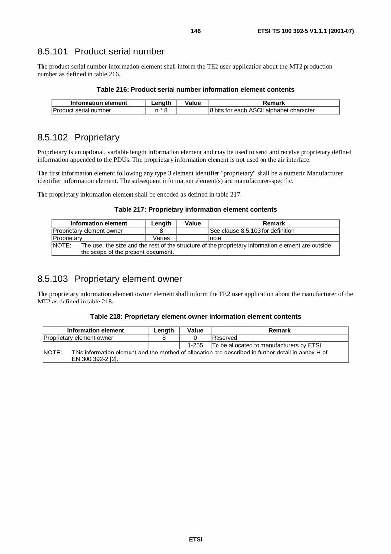
ETSI
ETSI TS 100 392-5 V1.1.1 (2001-07)146
8.5.101 Product serial number
The product serial number information element shall inform the TE2 user application about the MT2 productionnumber as defined in table 216.
Table 216: Product serial number information element contents
Information element Length Value RemarkProduct serial number n * 8 8 bits for each ASCII alphabet character
8.5.102 Proprietary
Proprietary is an optional, variable length information element and may be used to send and receive proprietary definedinformation appended to the PDUs. The proprietary information element is not used on the air interface.
The first information element following any type 3 element identifier "proprietary" shall be a numeric Manufactureridentifier information element. The subsequent information element(s) are manufacturer-specific.
The proprietary information element shall be encoded as defined in table 217.
Table 217: Proprietary information element contents
Information element Length Value RemarkProprietary element owner 8 See clause 8.5.103 for definitionProprietary Varies noteNOTE: The use, the size and the rest of the structure of the proprietary information element are outside
the scope of the present document.
8.5.103 Proprietary element owner
The proprietary information element owner element shall inform the TE2 user application about the manufacturer of theMT2 as defined in table 218.
Table 218: Proprietary element owner information element contents
Information element Length Value RemarkProprietary element owner 8 0 Reserved
1-255 To be allocated to manufacturers by ETSINOTE: This information element and the method of allocation are described in further detail in annex H of
EN 300 392-2 [2].
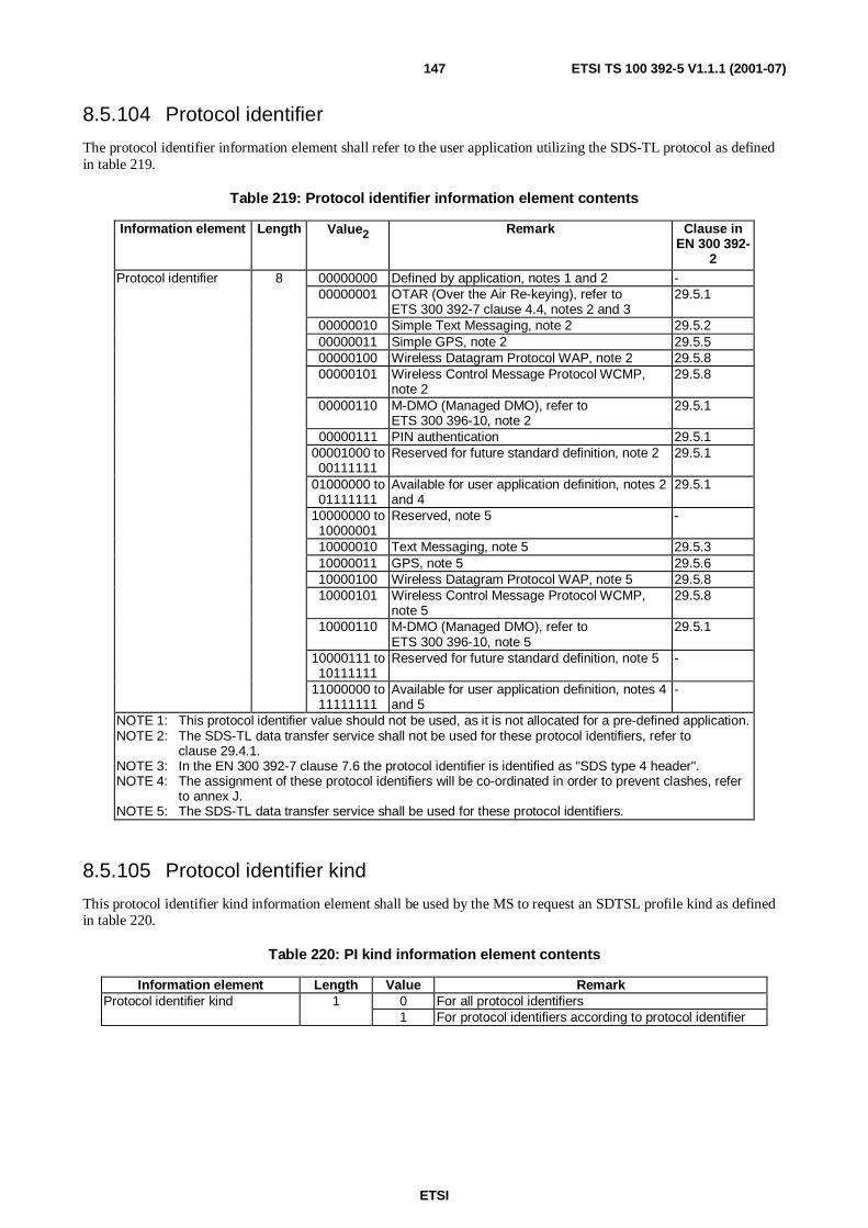
ETSI
ETSI TS 100 392-5 V1.1.1 (2001-07)147
8.5.104 Protocol identifier
The protocol identifier information element shall refer to the user application utilizing the SDS-TL protocol as definedin table 219.
Table 219: Protocol identifier information element contents
Information element Length Value2 Remark Clause inEN 300 392-
2Protocol identifier 8 00000000 Defined by application, notes 1 and 2 -
00000001 OTAR (Over the Air Re-keying), refer toETS 300 392-7 clause 4.4, notes 2 and 3
29.5.1
00000010 Simple Text Messaging, note 2 29.5.200000011 Simple GPS, note 2 29.5.500000100 Wireless Datagram Protocol WAP, note 2 29.5.800000101 Wireless Control Message Protocol WCMP,
note 229.5.8
00000110 M-DMO (Managed DMO), refer toETS 300 396-10, note 2
29.5.1
00000111 PIN authentication 29.5.100001000 to00111111
Reserved for future standard definition, note 2 29.5.1
01000000 to01111111
Available for user application definition, notes 2and 4
29.5.1
10000000 to10000001
Reserved, note 5 -
10000010 Text Messaging, note 5 29.5.310000011 GPS, note 5 29.5.610000100 Wireless Datagram Protocol WAP, note 5 29.5.810000101 Wireless Control Message Protocol WCMP,
note 529.5.8
10000110 M-DMO (Managed DMO), refer toETS 300 396-10, note 5
29.5.1
10000111 to10111111
Reserved for future standard definition, note 5 -
11000000 to11111111
Available for user application definition, notes 4and 5
-
NOTE 1: This protocol identifier value should not be used, as it is not allocated for a pre-defined application.NOTE 2: The SDS-TL data transfer service shall not be used for these protocol identifiers, refer to
clause 29.4.1.NOTE 3: In the EN 300 392-7 clause 7.6 the protocol identifier is identified as "SDS type 4 header".NOTE 4: The assignment of these protocol identifiers will be co-ordinated in order to prevent clashes, refer
to annex J.NOTE 5: The SDS-TL data transfer service shall be used for these protocol identifiers.
8.5.105 Protocol identifier kind
This protocol identifier kind information element shall be used by the MS to request an SDTSL profile kind as definedin table 220.
Table 220: PI kind information element contents
Information element Length Value RemarkProtocol identifier kind 1 0 For all protocol identifiers
1 For protocol identifiers according to protocol identifier

ETSI
ETSI TS 100 392-5 V1.1.1 (2001-07)148
8.5.106 Reject cause
The reject cause information element shall indicate what type of rejection has been detected as defined in table 221.
Table 221: Reject cause information element contents
Information element Length Value2 Remark
Reject Cause 5 00000 Reserved00001 ITSI unknown00010 Illegal MS00011 Location Area not allowed00100 Location Area unknown00101 Network failure00110 Congestion00111 Service not supported01000 Service not subscribed01001 Mandatory element error01010 Message consistency error01011 Roaming not supported01100 Migration not supported01101 No cipher KSG01110 Identified cipher KSG not supported01111 Requested cipher key type not available10000 Identified cipher key not available10001 Incompatible service10010 Reserved
etc. etc.11111 Reserved
8.5.107 Registration status
The registration status information element shall indicate the success/failure of the most recent registration attempt asdefined in table 222.
Table 222: Registration status information element contents
Information element Length Value RemarkRegistration status 1 0 Success
1 Failure
8.5.108 Registration type
The registration type information element shall indicate the registration type of the registration request as defined intable 223.
Table 223: Registration type information element contents
Information element Length Value Remark0 No new ITSI - periodic registration1 No new ITSI - forward registration
Registration type 2
2 New ITSI
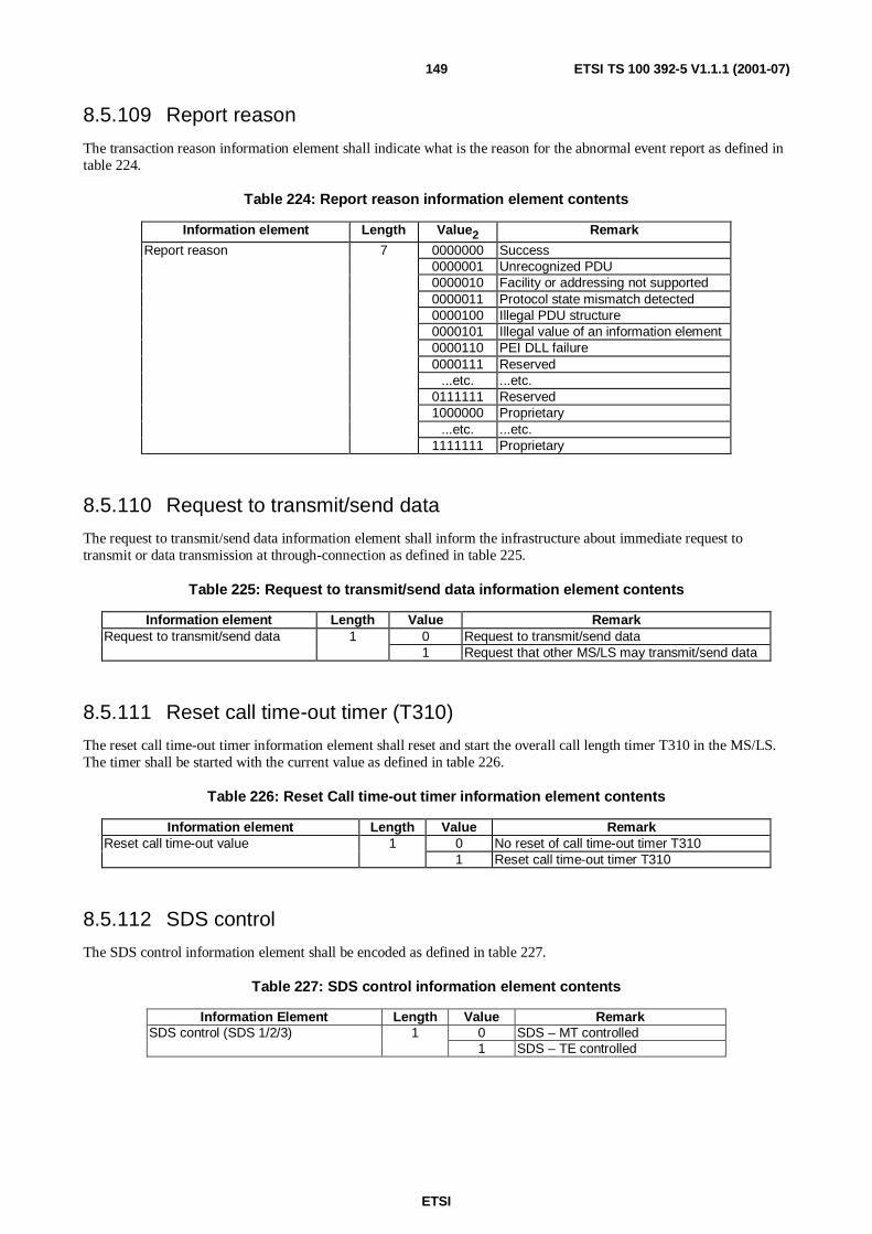
ETSI
ETSI TS 100 392-5 V1.1.1 (2001-07)149
8.5.109 Report reason
The transaction reason information element shall indicate what is the reason for the abnormal event report as defined intable 224.
Table 224: Report reason information element contents
Information element Length Value2 Remark
Report reason 7 0000000 Success0000001 Unrecognized PDU0000010 Facility or addressing not supported0000011 Protocol state mismatch detected0000100 Illegal PDU structure0000101 Illegal value of an information element0000110 PEI DLL failure0000111 Reserved
...etc. ...etc.0111111 Reserved1000000 Proprietary
...etc. ...etc.1111111 Proprietary
8.5.110 Request to transmit/send data
The request to transmit/send data information element shall inform the infrastructure about immediate request totransmit or data transmission at through-connection as defined in table 225.
Table 225: Request to transmit/send data information element contents
Information element Length Value RemarkRequest to transmit/send data 1 0 Request to transmit/send data
1 Request that other MS/LS may transmit/send data
8.5.111 Reset call time-out timer (T310)
The reset call time-out timer information element shall reset and start the overall call length timer T310 in the MS/LS.The timer shall be started with the current value as defined in table 226.
Table 226: Reset Call time-out timer information element contents
Information element Length Value RemarkReset call time-out value 1 0 No reset of call time-out timer T310
1 Reset call time-out timer T310
8.5.112 SDS control
The SDS control information element shall be encoded as defined in table 227.
Table 227: SDS control information element contents
Information Element Length Value Remark0 SDS – MT controlledSDS control (SDS 1/2/3) 11 SDS – TE controlled
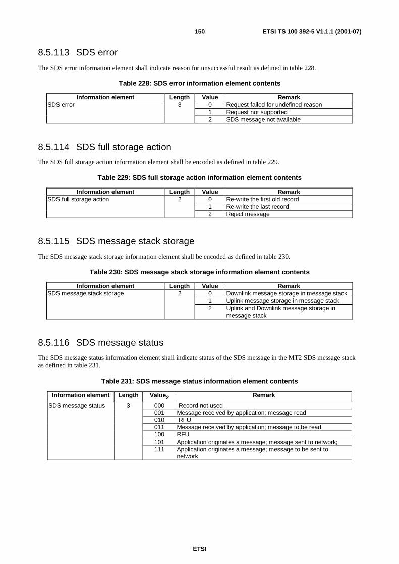
ETSI
ETSI TS 100 392-5 V1.1.1 (2001-07)150
8.5.113 SDS error
The SDS error information element shall indicate reason for unsuccessful result as defined in table 228.
Table 228: SDS error information element contents
Information element Length Value RemarkSDS error 3 0 Request failed for undefined reason
1 Request not supported2 SDS message not available
8.5.114 SDS full storage action
The SDS full storage action information element shall be encoded as defined in table 229.
Table 229: SDS full storage action information element contents
Information element Length Value RemarkSDS full storage action 2 0 Re-write the first old record
1 Re-write the last record2 Reject message
8.5.115 SDS message stack storage
The SDS message stack storage information element shall be encoded as defined in table 230.
Table 230: SDS message stack storage information element contents
Information element Length Value RemarkSDS message stack storage 2 0 Downlink message storage in message stack
1 Uplink message storage in message stack2 Uplink and Downlink message storage in
message stack
8.5.116 SDS message status
The SDS message status information element shall indicate status of the SDS message in the MT2 SDS message stackas defined in table 231.
Table 231: SDS message status information element contents
Information element Length Value2 Remark
000 Record not used001 Message received by application; message read010 RFU011 Message received by application; message to be read100 RFU101 Application originates a message; message sent to network;
SDS message status 3
111 Application originates a message; message to be sent tonetwork

ETSI
ETSI TS 100 392-5 V1.1.1 (2001-07)151
8.5.117 SDS mode services
The SDS mode services information element shall list the SDS mode capabilities of the MT2, as defined in table 232.
Table 232: SDS mode services information element contents
Information Element Length Value2 Remark
Status 1 0 Not capable1 Capable
SDS Type 1 1 0 Not capable1 Capable
SDS Type 2 1 0 Not capable1 Capable
SDS Type 3 1 0 Not capable1 Capable
SDS Type 4 2 00 Not capable01 Capable with SDS4 direct only10 Capable with TL and direct also11 Reserved
SDS message stack in MT2 1 0 Not capable1 Capable
Reserved 1 0 ReservedMT2 Default Gateway address 24 Conditional on one of the SDS capability
8.5.118 SDS profile type
The SDS profile type information element shall indicate the type of the SDS 1/2/3/status service profilerequested/indicated, as defined in table 233.
Table 233: SDS profile type information element contents
Information Element Length Value Remark0 Service profile for SDS 11 Service profile for SDS 22 Service profile for SDS 3
SDS profile type 8
3 Service profile for SDS status
8.5.119 SDS reference type
The SDS reference type information element shall be defined in table 234.
Table 234: SDS reference type information element contents
Information element Length Value Remark0 Message reference handle + message
reference1 Message reference2 User application reference
SDS reference type 2
3 Reserved

ETSI
ETSI TS 100 392-5 V1.1.1 (2001-07)152
8.5.120 SDS stack message handling
The SDS stack message handling information element shall be encoded as defined in table 235.
Table 235: SDS stack message handling information element contents
Information element Length Value Type C/O/M RemarkStack usage 1 any 1 M note 1SDS message stack storage 2 any C note 1, note 2SDS full storage action 2 any C note 1, note 2SDS validity period 5 any C note 1, note 2NOTE 1: Relevant only when MT has a stack capability (see SDS mode services).NOTE 2: Shall be conditional on the value of the "Stack usage" (SU):
- SU = 1: SDS message stack storage + SDS Full Storage action + SDS validity period;- SU = 0: Shall not be present.
8.5.121 SDS status profile
The SDS status profile information element shall be encoded as defined in table 236.
Table 236: SDS status profile information element contents
Information element Length Type C/O/M Value RemarkSDS stack message handling According to the definitionUser status control, note 1 1 M 0 User status - MT controlled
1 User status - TE controlledDefault status control, note 1 1 M 0 Other status - MT controlled
1 Other status - TE controlledNOTE: User Status is defined as Status with values: 8000-EFFF.
For other status values, no additional profile is required:- Status Ack (defined as FE00-FE0F) – both applications will receive;- SDS-TL short reporting (defined as 7B00-7FFF) – according to SDS-TL profile;- Emergency alarm- both applications can send the message;- Call back request (defined as FEFF or FEFC) – according to the Call control profile;- Other – as defined in default status control.
8.5.122 SDS type
The SDS type information element shall indicate type of the SDS message in the MT2 SDS message stack as defined intable 237.
Table 237: SDS type information element contents
Information element Length Value RemarkSDS type 3 0 SDS type 1
1 SDS type 22 SDS type 33 SDS status4 SDS type 4

ETSI
ETSI TS 100 392-5 V1.1.1 (2001-07)153
8.5.123 SDS user data 1 profile
The SDS user data 1 profile information element shall define operation of the TNP1 Relay for SDS type 1 messages asdefined in table 238.
Table 238: SDS user data 1 profile information element contents
Information element Length Value RemarkSDS control 1 anySDS stack message handling
8.5.124 SDS user data 2 profile
The SDS user data 2 profile information element shall define operation of the TNP1 Relay for SDS type 2 messages.The format shall be as in SDS user data profile 1.
8.5.125 SDS user data 3 Profile
The SDS user data 3 profile information element shall define operation of the TNP1 Relay for SDS type 3 messages.The format shall be as in SDS user data profile 1.
8.5.126 SDS user data 4 Profile
The SDS user data 4 profile information element shall define operation of the TNP1 Relay for SDS type 4 messages ofa certain SDS type 4 protocol. The SDS user data 4 profile information element shall define operation of the TNP1Relay for SDS type 4 messages. The format shall be as in SDS user data profile 1.
8.5.127 SDS-TL service capability
The SDS service capability information element shall list the SDS-TL capability of the MT2 as defined in table 239.
Table 239: SDS-TL service capability information element contents
Information Element Length ValueSDS-TL service capability 1 0 Not capable
1 Capable
8.5.128 SDS-TL service centre address type
The SDS service centre address type information element shall list the SDS-TL capability of the MT2 as defined intable 240.
Table 240: SDS-TL service centre address type information element contents
Information element Length Value RemarkSDS-TL service centre address type 3 0 Short Number Address (SNA)
1 Short Subscriber Identity (SSI)2 Tetra Subscriber Identity (TSI = MNI+SSI)3 SSI+ESN

ETSI
ETSI TS 100 392-5 V1.1.1 (2001-07)154
8.5.129 SDS-TL service centre capability
The SDS-TL service centre capability information element shall list the service centre capability of the MT2 as definedin table 241.
Table 241: SDS-TL service centre capability information element contents
Information Element Length Value RemarkSDS-TL service centre capability 1 0 Not capable
1 Capable
8.5.130 SDS-TL service centre default address
The SDS-TL service default address information element shall indicate the service centre default address as defined intable 242.
Table 242: SDS-TL service centre default address information element contents
Information element Length Value Type C/O/M RemarkSDS-TL service centre address type 3 any 1 MShort number address (SNA) 8 any noteSSI 24 noteExtension 24 noteExternal subscriber number noteNOTE: Shall be conditional on the service centre address type
8.5.131 SDS transfer result
The SDS transfer result information element shall inform the TE2 user application about the success of the SDStransmittal as defined in table 243.
Table 243: SDS transfer result information element contents
Information element Length2 Value2 Remark
SDS transfer result 8 00000000 Failed for undefined reason00000001 Success00000010 Requested service not supported
8.5.132 Security
The security information element shall indicate the security capabilities of MT2 as defined in table 244.
Table 244: Security information element contents
Information element Length Value Type C/O/M RemarkSecurity class of MS 2 any 1 MEnd to end encryption flag 1 any 1 M

ETSI
ETSI TS 100 392-5 V1.1.1 (2001-07)155
8.5.133 Security class of MS
The security class information element shall indicate the security class of MS as defined in table 245.
Table 245: Security class of MS information element contents
Information element Length Value RemarkSecurity class of MS 2 0 Security class 1
1 Security class 22 Security class 3
8.5.134 Security information
The information element security information shall indicate the security information included in the extended servicesbroadcast information, as defined in table 246.
Table 246: Security information element contents
Information sub-element Length Type C/O/M Value Remark0 Authentication not required in this cellAuthentication 1 1 M1 Authentication required in this cell0 Security class 1 MS not supported on this cellSecurity class 1 1 1 M1 Security class 1 MS supported on this cell0 Security class 2 MS supported on this cellSecurity class 2 or 3 1 1 M1 Security class 3 MS supported on this cell
SCKN (note 1) 5 C any0 Service not supportedDCK retrieval during initial cell
selection (note 2)1 C
1 Service supported0 Service not supportedDCK retrieval during cell
re-selection (note 2)1 C
1 Service supported0 Service not supportedGCK supported
Note 21 C
1 Service supportedNOTE 1: Shall be conditional on the value of "security class 2 or 3" (sc23):
- SC23= 0; SCKN;- SC23=1.
NOTE 2: Shall be conditional on the value of "security class 2 or 3" (sc23):- SC23=1; DCK retrieval during initial cell selection + DCK retrieval during cell re-selection + GCK
supported;- SC23=0.
8.5.135 Service profile operation
The service profile operation information element shall specify the operation performed on the TNP1 Relay serviceprofile as defined in table 247.
Table 247: Service profile operation information element contents
Information element Length Value RemarkService profile operation 2 0 Get service profile
1 Set service profile2-3 Reserved

ETSI
ETSI TS 100 392-5 V1.1.1 (2001-07)156
8.5.136 Service profile request result
The service profile request result information element shall specify if the set request was successful or not as defined intable 248.
Table 248: Service Profile request result information element contents
Information element Length Value Remark0 Unsuccessful1 Success2 Not applicable
Service profile request result 2
3 Unsupported feature
8.5.137 Service selection
The service selection information element shall indicate which of the service selection is indicated as defined intable 249.
Table 249: Service selection information element contents
Information element Length Value RemarkService selection 1 0 Individual service
1 Group or individual service
8.5.138 Service status
The service status information element shall indicate which of the service status is indicated as defined in table 250.
Table 250: Service status information element contents
Information element Length Value RemarkService status 2 0 In service
1 In service waiting for registration2 Out of service
8.5.139 Set profile request
The set profile request information element shall indicate which one of the set operation for the profile set request PDUis requested as defined in table 251.
Table 251: Set profile request information element contents
Information element Length Value RemarkSet operation profile request 8 0 Set current service profile
1 Set current service profile and store as userdefined Service profile
2 Restore user defined service profile (to thecurrent service profile)
3 Restore default service profile (to the currentservice profile)
4-255 Reserved

ETSI
ETSI TS 100 392-5 V1.1.1 (2001-07)157
8.5.140 Short data type identifier
The short data type identifier information element shall identify the length of the user-defined data sent to or receivedfrom the SwMI as defined in table 252.
Table 252: Short DATA TYPE IDENTIFIER information element contents
Information element Length Value RemarkShort data type identifier 2 0 User defined data 1 element is 16 bits long
1 User defined data 2 element is 32 bits long2 User defined data 3 element is 64 bits long3 User defined data 4 element is 0 - 2 047 bits long
(variable length)
8.5.141 Short form report
The short form report information element shall indicate request for short report as defined in table 253.
Table 253: Short form report information element contents
Information element Length Value RemarkShort form report 1 0 Short form report recommended during the
validity period of the message1 Only standard report allowed
8.5.142 Simplex/duplex selection
The simplex/duplex selection information element shall inform the infrastructure the preferred mode of operation asdefined in table 254.
Table 254: simplex/duplex selection information element contents
Information element Length Value RemarkSimplex/duplex selection 1 0 Simplex requested
1 Duplex requested
8.5.143 Software version
The software version information element shall inform the TE2 user application about the MT2 software version asdefined in table 255. The total number of characters, including line terminators, shall not exceed 128 characters.
Table 255: Software version information element contents
Information element Length2 Value Remark
Software version n x 8 8 bits for each ASCI I alphabet character
8.5.144 Speaker on off
The speaker on off information element shall be as defined in table 256.
Table 256: Speaker on off information element contents
Information element Length Value Remark0 Speaker OffSpeaker on off 11 Speaker On

ETSI
ETSI TS 100 392-5 V1.1.1 (2001-07)158
8.5.145 SS PDU type
The SS PDU type information element is a mandatory information element and shall be the next element after SS typein every SS PDU. The information element encoding shall be as defined in EN 300 392-9 [15] clause 8.2.
8.5.146 SS type
The SS type information element shall specify the SS in question. The information element encoding shall be as definedin EN 300 392-9 [15] clause 8.1 for the SS type information element.
8.5.147 SSI
The SSI information element shall indicate the ASSI or (V) ASSI that the MS shall use in subsequent contacts with theSwMI as defined in table 257.
Table 257: Short Subscriber Identifier information element contents
Information element Length Value RemarkShort Subscriber Identity (SSI) 24 See ETS 300 392-1 [1], clause 7
8.5.148 Stack usage
The stack usage information element shall give information indicating if the stack is used as defined in table 258.
Table 258: stack usage information element contents
Information element Length Value Remark0 The messages are not stored in the stackStack usage 11 The messages are stored in the stack
8.5.149 Status number
The status number information element shall define general-purpose status messages known to all TETRA systems asdefined in EN 300 392-2 [2] and repeated in table 259.
Table 259: Status number information element contents
Information element Length Value RemarkStatus number 16 0 Emergency
1 Reservedetc. etc.
32 767 Reserved32 768 Available for TETRA network and user specific definitions
etc. etc.65 535 Available for TETRA network and user specific definitions
8.5.150 Storage
The storage information element shall indicate if the SwMI is allowed to store the message as defined in table 260.
Table 260: Storage information element contents
Information element Length Value RemarkStorage 1 0 Storage not allowed
1 Storage allowed

ETSI
ETSI TS 100 392-5 V1.1.1 (2001-07)159
8.5.151 Store and forward PDU capability
The Store and forward capability information element shall give information on what PDUs store and forward are usedas defined in table 261.
Table 261: Store and forward PDU capability information element content
Information element Length Value RemarkStore and forward PDU capability 2 0 None
1 Transfer2 Transfer Report3 Transfer Report Ack
8.5.152 Terminal Equipment Identity (TEI)
TEI information element shall contain the TEI value of the MT2 as defined in ETS 300 392-1 [1] clause 7.5 andrepeated in table 262.
Table 262: TEI information element contents
Information element Length Value RemarkType Approval Code (TAC) 24 8 characters (note)Final Assembly Code (FAC) 8 3 characters (note)Electronic Serial Number (ESN) 24 8 characters (note)Spare (SPR) 4 ReservedNOTE: Each information element is a binary number and its values shall be presented as printable ASCII
characters from "0" to "9", most significant digit placed first.
8.5.153 Traffic stealing
The traffic stealing information element shall inform the MS/LS about preferred stealing policy as defined in table 263.
Table 263: Traffic stealing information element contents
Information element Length2 Value Remark
Traffic Stealing 1 0 Do not steal traffic1 Steal traffic
8.5.154 TNP1 protocol version
The TNP1 protocol version information element shall inform the TE2 user application about the MT2 TNP1 protocolversion as defined in table 264. The TNP1 protocol version shall contain the version of the present document.
The format of the TNP1 protocol version shall be according to the following rule: V1.2.1CRxxx where the V1.2.1represent the version of the present document and the CRxxx represent the change request. The details how changerequest number is allocated is outside the scope of the present document.
Table 264: Protocol version information element contents
Information element Length Value RemarkTNP1 protocol version n*8 8 bits for each ASCII alphabet character
8.5.155 TNP1 release
The TNP1 release information element is devoted for free text manufacture dependent, as defined in table 265. Thelength of the TNP1 release information element is outside the scope of the present document.

ETSI
ETSI TS 100 392-5 V1.1.1 (2001-07)160
Table 265: TNP1 release information element contents
Information element Length Value RemarkTNP1 release N*8 8 bits for each ASCII alphabet character
8.5.156 Transmission condition
The transmission condition information element shall inform the MS/LS about requested transmission condition asdefined in table 266.
Table 266: Transmission condition information element contents
Information element Length Value RemarkTransmission condition 1 0 Request to transmit
1 Transmission ceased
8.5.157 Transmission grant
The transmission grant information element shall inform the MS/LS about permission to transmit as defined intable 267.
Table 267: Transmission grant information element contents
Information element Length Value RemarkTransmission grant 2 0 Transmission granted
1 Transmission not granted2 Transmission request queued3 Transmission granted to another user
8.5.158 Transmission request permission
The transmission request permission information element shall inform the MS/LS if it is allowed to request for transmitpermission as defined in table 268.
Table 268: Transmission request permission information element contents
Information element Length Value RemarkTransmission request permission 1 0 Allowed to request for transmission
1 Not allowed to request for transmission
8.5.159 Transmission status
The transmission status information element shall be encoded as defined in table 269.
Table 269: Transmission status information element content
Information element Length Value2 Remark
Transmission status 3 000 Transmission ceased001 Transmission granted010 Transmission not granted011 Transmission request queued100 Transmission granted to another user101 Transmission interrupt110 Transmission wait111 Transmission request failed

ETSI
ETSI TS 100 392-5 V1.1.1 (2001-07)161
8.5.160 Transmitting party extension
The transmitting party extension information element shall indicate the extended part of the TSI address of thetransmitting user as defined in table 270.
Table 270: Transmitting party extension information element contents
Information element Length Value RemarkCountry Code 10 any See ETS 300 392-1 [1] clause 7Network Code 14 any See ETS 300 392-1 [1] clause 7
8.5.161 Transmitting party Short Subscriber Identity (SSI)
The transmitting party Short Subscriber Identity information element shall indicate the Short Subscriber Identity (SSI)address of the transmitting user as defined in table 271.
Table 271: Transmitting party Short Subscriber Identity information element contents
Information element Length Value RemarkShort subscriber identity 24 See ETS 300 392-1 [1] clause 7
8.5.162 Transmitting party type identifier
The transmitting party type identifier information element coding shall indicate the type of address, which shall followin the PDU as defined in table 272.
Table 272: Transmitting party type identifier information element contents
Information element Length Value RemarkTransmitting party type identifier 2 0 Reserved
1 Short Subscriber Identity (SSI)2 Tetra Subscriber Identity (TSI)3 Reserved
8.5.163 TX demand priority
The TX demand priority information element shall inform the SwMI about the importance of a TX-Demand as definedin table 273.
Table 273: TX demand priority information element contents
Information element Length Value RemarkTX demand priority 2 0 Low Priority level
1 High Priority level2 Pre-emptive Priority level3 Emergency Pre-emptive Priority level

ETSI
ETSI TS 100 392-5 V1.1.1 (2001-07)162
8.5.164 Type 3 CMCE element identifier
The Type 3 CMCE element identifier information element shall indicate the type of the following Type 3 element in thecircuit mode and short data PDUs as defined in table 274.
Table 274: Type 3 CMCE element identifier information element contents
Information element Length Value2 Remark
Type 3 CMCE element identifier 4 0000 Reserved0001 DTMF0010 External Subscriber number0011 Facility0100 Poll Response Addresses0101 Proprietary0110 Reserved for future Type 3 CMCE element...etc ...etc.1111 Reserved for future Type 3 CMCE element
8.5.165 Type 3 MM element identifier
The Type 3 MM element identifier information element shall indicate the type of the following Type 3 element in themobility management PDUs as defined in table 275.
Table 275: Type 3 MM element identifier information element contents
Information element Length Value2 Remark
Type 3 MM element identifier 4 0000 Reserved0001 Group identity location demand Ack0010 New registered area0011 Group identity location demand0100 Proprietary0101 Group identity location accept0110 Security0111 Group identity downlink1000 Group identity uplink1001 Reserved for future Type 3 MM elementetc. etc.
1111 Reserved for future Type 3 MM element

ETSI
ETSI TS 100 392-5 V1.1.1 (2001-07)163
8.5.166 Type 3 MTA element identifier
The Type 3 MTA element identifier information element shall indicate the type of the following Type 3 element in theMT application PDUs as defined in table 276.
Table 276: Type 3 MTA element identifier information element contents
Information element Length Value2 Remark
Type 3 MTA element identifier 4 0000 Reserved0001 Manufacturer Identifier0010 Model0011 Software Version0100 Hardware Version0101 Product Serial No0110 ISO Global Object ID0111 TNP1 Protocol Version1000 TNP1 Release1001 Proprietary1010 Reserved for future Type 3 MTA element...etc. ...etc.1111 Reserved for future Type 3 MTA element
8.5.167 Type 3 SS element identifier
The Type 3 SS element identifier information element shall indicate the type of the following Type 3 element in theSupplementary services PDUs as defined in table 277.
Table 277: Type 3 SS element identifier information element contents
Information element Length Value2 Remark
Type 3 SS element identifier 4 0000 Reserved0001 SS PDU type0010 SS facility parameters0011 Proprietary0100 Reserved for future Type 3 SS element...etc. ...etc.1111 Reserved for future Type 3 SS element
8.5.168 User application reference
The User application reference information element shall be used in local SDS and SDS-TL report indication as definedin table 278.
Table 278: User Application Reference element identifier information element contents
Information element Length Value RemarkUser application reference 8
8.5.169 User data
The user data information element shall contain the application data as defined in table 279.
Table 279: User data information element contents
Information element Length Value RemarkUser data Varies All bits available for the user application

ETSI
ETSI TS 100 392-5 V1.1.1 (2001-07)164
8.5.170 User defined data-1
The user defined data-1 information element shall enable the user applications to determine their own interpretation ofthe SDS message as defined in table 280.
Table 280: User defined data-1 information element contents
Information element Length Value RemarkUser defined data-1 16 0 - (216-1) All values available for the user application
8.5.171 User defined data-2
The user defined data-2 information element shall enable the user applications to determine their own interpretation ofthe SDS message as defined in table 281.
Table 281: User defined data-2 information element contents
Information element Length Value RemarkUser defined data-2 32 0 - (232 - 1) All values available for the user application
8.5.172 User defined data-3
The user defined data-3 information element shall enable the user applications to determine their own interpretation ofthe SDS message as defined in table 282.
Table 282: User defined data-3 information element contents
Information element Length Value RemarkUser defined data-3 64 0 - (264 - 1) All values available for the user application
8.5.173 User defined data-4
The user defined data-4 information element shall enable the user applications to determine their own interpretation ofthe SDS message as defined in table 283.
Table 283: User Defined Data-4 information element contents
Information element Length Value RemarkProtocol identifier 8 any Refer to EN 300 392-2 [2] clause 29.4.3.9.User defined data-4 varies
0 - (2 047-8) bitsVaries All bits available for the user application
8.5.174 Visitor Group Short Subscriber Identity (V)GSSI
The (V)GSSI information element shall indicate that the MS shall use in subsequent contacts with the SwMI as definedin table 284.
Table 284: Visitor Group Short Subscriber Identity information element contents
Information element Length Value RemarkVisitor Group Short Subscriber Identity 24 See ETS 300 392-1 [1]
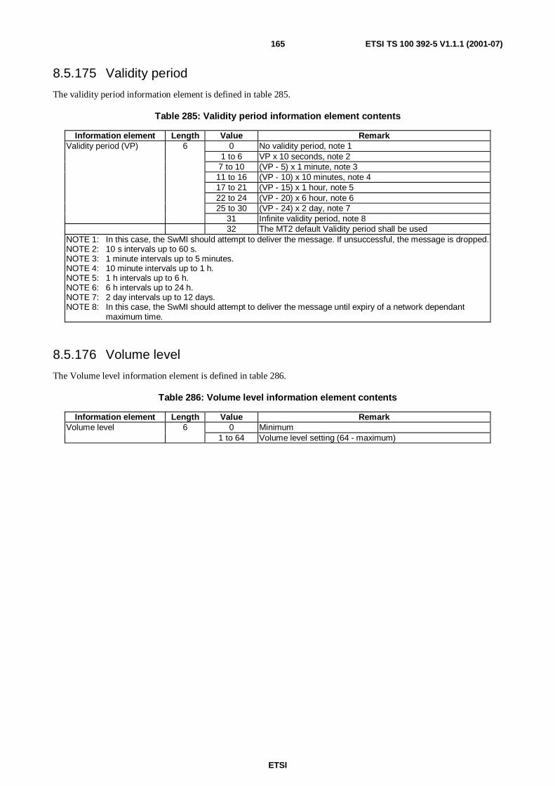
ETSI
ETSI TS 100 392-5 V1.1.1 (2001-07)165
8.5.175 Validity period
The validity period information element is defined in table 285.
Table 285: Validity period information element contents
Information element Length Value RemarkValidity period (VP) 6 0 No validity period, note 1
1 to 6 VP x 10 seconds, note 27 to 10 (VP - 5) x 1 minute, note 311 to 16 (VP - 10) x 10 minutes, note 417 to 21 (VP - 15) x 1 hour, note 522 to 24 (VP - 20) x 6 hour, note 625 to 30 (VP - 24) x 2 day, note 7
31 Infinite validity period, note 832 The MT2 default Validity period shall be used
NOTE 1: In this case, the SwMI should attempt to deliver the message. If unsuccessful, the message is dropped.NOTE 2: 10 s intervals up to 60 s.NOTE 3: 1 minute intervals up to 5 minutes.NOTE 4: 10 minute intervals up to 1 h.NOTE 5: 1 h intervals up to 6 h.NOTE 6: 6 h intervals up to 24 h.NOTE 7: 2 day intervals up to 12 days.NOTE 8: In this case, the SwMI should attempt to deliver the message until expiry of a network dependant
maximum time.
8.5.176 Volume level
The Volume level information element is defined in table 286.
Table 286: Volume level information element contents
Information element Length Value RemarkVolume level 6 0 Minimum
1 to 64 Volume level setting (64 - maximum)

ETSI
ETSI TS 100 392-5 V1.1.1 (2001-07)166
Annex A (normative):Formatting transparent circuit mode data to MAC PDUThe MAC-TRAFFIC PDU is used for sending U-plane traffic data on the uplink and downlink using TCH/S, TCH/7.2,TCH/4.8 or TCH/2.4, as defined in EN 300 392-2 [2], clause 21.4.6. This PDU has no header and all capacity isdevoted to traffic information passed to and from the U-plane. When the MAC is in traffic mode, this PDU type isassumed unless the slot flag indicates the presence of the STCH.
This annex defines the formatting of transparent circuit mode data in the MAC-TRAFFIC PDU. This formatting shouldbe used for all transparent circuit mode data originating from/targeted to TE2 over RT and applications internal to MT2.Figure A.1 defines the general formatting to be applied to all TCHs. The Most Significant Bit (MSB) of any octet isplaced in the MAC TRAFFIC PDU bit with the smallest ordinal number. Values for total number of octets (N) and totalnumber of bits (B) per a MAC TRAFFIC PDU are defined in table A.1 for different TCHs.
Octet 1 2 ...etc. NMAC block bit 1 ... 8 9 ... 16 ...etc. (B - 8) ... B
Figure A.1: Octet and bit alignment in MAC TRAFFIC PDU
Table A.1: Capacity of a single MAC TRAFFIC PDU at different logical channels
Logicalchannel
Number of data bits(B)
Octets/timeslot(N)
TCH/7,2 432 54TCH/4,8 288 36TCH/2,4 144 18
The 8-bit (octet) formatting defined in this annex should be used as basic formatting to transfer transparent mode data ofany character length. For other character lengths than 8-bit, a mapping to this basic formatting should be defined atapplication level.
NOTE: This mechanism removes all redundant information from the serial line lower layer character format andno information about possible parity bit or number of stop bits will be transferred over the AI. As a resulte.g. 4 800 bit/s second low protected data rate is equivalent to 6 600 bit/s, when the serial line interfaceapplies start bit, eight information bits, parity bit and one stop bit.
For half MAC blocks, the same octet and bit ordering and alignment should apply.

ETSI
ETSI TS 100 392-5 V1.1.1 (2001-07)167
Annex B (informative):DMO ConsiderationsThis is annexe is a reminder of the need for DMO to be included in a later edition of the present document. Both ATand TNP1 will need commands for DMO. WG8 is concerned with DMO and will have an input to this clause.
The context diagram will need updating to include DMO.
Features that will affect the DMO commands are:
• Select DMO or TMO mode. The mode command should differentiate TMO, DMO, dual watch, repeater andgateway modes. The profile, capability and service definition commands would then apply to the selected mode.
• The addressing during DMO mode may be different due to the repeater and gateway identities. This may need achange of the call set up commands or a new command to set the repeater or gateway address.
• An additional command to indicate DM channel state (available, occupied, reserved) and "in repeater range".
• The selection of DMO RF carrier and colour code. The reverse direction - to get the information on whatchannels and colour codes are available. The colour codes could be related to the MNI
• There is no MM information in DMO.
• There are additional values for call set up and clear down elements, conversely some TMO reasons are notapplicable
• There are no full duplex calls in DMO.
• There is no packet data in DMO.
• There is no multi slot data in DMO.
• There are only four levels of priority in DMO (15 in TMO).
• DMO has acknowledged SDS transfer.

ETSI
ETSI TS 100 392-5 V1.1.1 (2001-07)168
Annex C (informative):Supplementary Services ConsiderationsThis annex is a place marker for future editions. When the air interface supplementary services become stable the PEIwill have to cater for transfer of this information to and from the TE. The vehicle for supplementary services will be theSS facility elements. The coding of air interface SS facility elements will involve packing the air interface element bitsinto octets for use on the PEI.
ETSI
ETSI TS 100 392-5 V1.1.1 (2001-07)169
Annex D (informative):Supported functionality and PPP optionsAt the initial publication date of the present standard, the following functionality and PPP options are supported in someMT2s on the market:
• Single PDP context;
• Context activation and context deactivation;
• Datagram relay from TE to SwMI and from SwMI to TE;
• IP static and dynamic addressing;
• IP user authentication;
• Header compression.
The following functionality may not available at present:
• Multiple PDP contexts;
• IP broadcast and multicast;
• Data compression;
• Mobile IPv4;
• IPv6 addressing.

ETSI
ETSI TS 100 392-5 V1.1.1 (2001-07)170
Annex E (informative):BibliographyTIA TIA/EIA/IS-135 (1995) (Withdrawn): "800 MHz Cellular Systems TDMA Services Async Data and Fax".

ETSI
ETSI TS 100 392-5 V1.1.1 (2001-07)171
History
Document history
V1.1.1 July 2001 Publication