trusted opc server package - rockwell automation...trusted opc server package . product overview ....
TRANSCRIPT
PD-T8030 Trusted
Rockwell Automation Publication PD-T8030 Issue 24
Trusted OPC Server Package
Product Overview
The OPC (OLE for Process Control) Server Package is a Windows based software application that allows OPC compatible clients to connect to a Trusted® System and access the process data.
This document describes the Open Platform Communication (OPC) server in its Windows Service form (T8030S). For OPC Server release 17 and earlier and other executable versions (T8030X), please refer to issue 14 of this document.
Features:
• Industry standard OPC interface.
• Supports OPC Data Access v1.0, v2.05a and OPC Alarms & Events v1.1.
• Single or Dual-redundant link to a Trusted System.
• Handles up to 32 Trusted Controllers.
• Update rate of down to 10 ms.
• Events time-stamped to a resolution of 1 ms.
• Collects sequence of events (SOE) and process historian data.
• Automatically interfaces to IEC 61131 TOOLSET to obtain tag references in Trusted Controllers.
• Online monitoring of tag values.
• Reports communications and server status to Clients.
• Operates as a Windows Service regardless of user login (T8030S).

Trusted PD-T8030
Rockwell Automation Publication PD-T8030 Issue 24
Page intentionally left blank
Trusted OPC Server Package PREFACE
Rockwell Automation Publication PD-T8030 Issue 24 i
PREFACE
In no event will Rockwell Automation be responsible or liable for indirect or consequential damages resulting from the use or application of this equipment. The examples given in this manual are included solely for illustrative purposes. Because of the many variables and requirements related to any particular installation, Rockwell Automation does not assume responsibility or reliability for actual use based on the examples and diagrams.
No patent liability is assumed by Rockwell Automation, with respect to use of information, circuits, equipment, or software described in this manual.
All trademarks are acknowledged.
DISCLAIMER
It is not intended that the information in this publication covers every possible detail about the construction, operation, or maintenance of a control system installation. You should also refer to your own local (or supplied) system safety manual, installation and operator/maintenance manuals.
REVISION AND UPDATING POLICY
This document is based on information available at the time of its publication. The document contents are subject to change from time to time. The latest versions of the manuals are available at the Rockwell Automation Literature Library under "Product Information" information "Critical Process Control & Safety Systems".
TRUSTED RELEASE
This technical manual applies to Trusted Release: 3.6.1.
LATEST PRODUCT INFORMATION
For the latest information about this product review the Product Notifications and Technical Notes issued by technical support. Product Notifications and product support are available at the Rockwell Automation Support Centre at http://rockwellautomation.custhelp.com
At the Search Knowledgebase tab select the option "By Product" then scroll down and select the Trusted product.
Some of the Answer ID’s in the Knowledge Base require a TechConnect Support Contract. For more information about TechConnect Support Contract Access Level and Features please click on the following link:
https://rockwellautomation.custhelp.com/app/answers/detail/a_id/50871
This will get you to the login page where you must enter your login details.

PREFACE Trusted OPC Server Package
ii Issue 24 Rockwell Automation Publication PD-T8030
IMPORTANT A login is required to access the link. If you do not have an account then you can create one using the "Sign Up" link at the top right of the web page.
DOCUMENTATION FEEDBACK
Your comments help us to write better user documentation. If you discover an error, or have a suggestion on how to make this publication better, send your comment to our technical support group at http://rockwellautomation.custhelp.com
Trusted OPC Server Package PREFACE
Rockwell Automation Publication PD-T8030 Issue 24 iii
SCOPE
This manual specifies the maintenance requirements and describes the procedures to assist troubleshooting and maintenance of a Trusted system.
WHO SHOULD USE THIS MANUAL
This manual is for plant maintenance personnel who are experienced in the operation and maintenance of electronic equipment and are trained to work with safety systems.
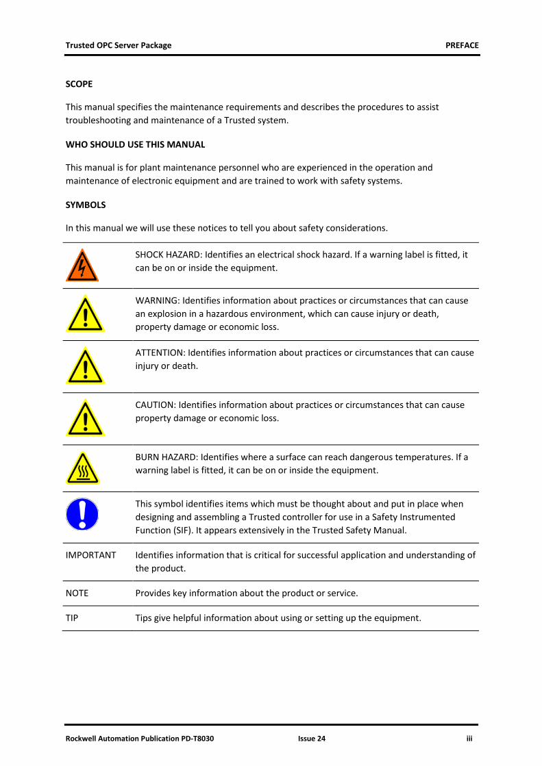
SYMBOLS
In this manual we will use these notices to tell you about safety considerations.
SHOCK HAZARD: Identifies an electrical shock hazard. If a warning label is fitted, it can be on or inside the equipment.
WARNING: Identifies information about practices or circumstances that can cause an explosion in a hazardous environment, which can cause injury or death, property damage or economic loss.
ATTENTION: Identifies information about practices or circumstances that can cause injury or death.
CAUTION: Identifies information about practices or circumstances that can cause property damage or economic loss.
BURN HAZARD: Identifies where a surface can reach dangerous temperatures. If a warning label is fitted, it can be on or inside the equipment.
This symbol identifies items which must be thought about and put in place when designing and assembling a Trusted controller for use in a Safety Instrumented Function (SIF). It appears extensively in the Trusted Safety Manual.
IMPORTANT Identifies information that is critical for successful application and understanding of the product.
NOTE Provides key information about the product or service.
TIP Tips give helpful information about using or setting up the equipment.
PREFACE Trusted OPC Server Package
iv Issue 24 Rockwell Automation Publication PD-T8030
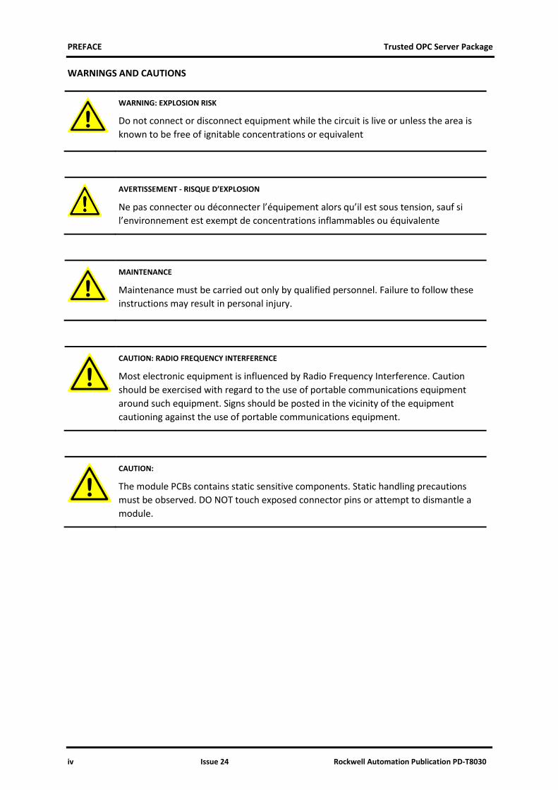
WARNINGS AND CAUTIONS
WARNING: EXPLOSION RISK
Do not connect or disconnect equipment while the circuit is live or unless the area is known to be free of ignitable concentrations or equivalent
AVERTISSEMENT - RISQUE D’EXPLOSION
Ne pas connecter ou déconnecter l’équipement alors qu’il est sous tension, sauf si l’environnement est exempt de concentrations inflammables ou équivalente
MAINTENANCE
Maintenance must be carried out only by qualified personnel. Failure to follow these instructions may result in personal injury.
CAUTION: RADIO FREQUENCY INTERFERENCE
Most electronic equipment is influenced by Radio Frequency Interference. Caution should be exercised with regard to the use of portable communications equipment around such equipment. Signs should be posted in the vicinity of the equipment cautioning against the use of portable communications equipment.
CAUTION:
The module PCBs contains static sensitive components. Static handling precautions must be observed. DO NOT touch exposed connector pins or attempt to dismantle a module.
Trusted OPC Server Package PREFACE
Rockwell Automation Publication PD-T8030 Issue 24 v
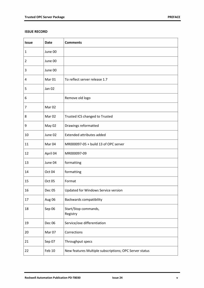
ISSUE RECORD
Issue Date Comments
1 June 00
2 June 00
3 June 00
4 Mar 01 To reflect server release 1.7
5 Jan 02
6 Remove old logo
7 Mar 02
8 Mar 02 Trusted ICS changed to Trusted
9 May 02 Drawings reformatted
10 June 02 Extended attributes added
11 Mar 04 MR000097-05 + build 13 of OPC server
12 April 04 MR000097-09
13 June 04 formatting
14 Oct 04 formatting
15 Oct 05 Format
16 Dec 05 Updated for Windows Service version
17 Aug 06 Backwards compatibility
18 Sep 06 Start/Stop commands, Registry
19 Dec 06 Service/exe differentiation
20 Mar 07 Corrections
21 Sep 07 Throughput specs
22 Feb 10 New features Multiple subscriptions; OPC Server status

PREFACE Trusted OPC Server Package
vi Issue 24 Rockwell Automation Publication PD-T8030
Issue Date Comments
23 April 10 Features minor change
24 Jun 16 Rebranded and updated to incorporate IEEE standards with correction of typographical errors.
Trusted OPC Server Package Table of Contents
Rockwell Automation Publication PD-T8030 Issue 24 1
Table of Contents
1. Description ............................................................................................................. 3
1.1. Overview ..................................................................................................................................... 3 1.2. Trusted OPC Architecture ........................................................................................................... 4
1.2.1. The Browse Interface .......................................................................................................... 4 1.2.2. OPC Data Access Interface .................................................................................................. 4 1.2.3. OPC Alarm & Event Interface .............................................................................................. 5 1.2.4. OPC Data Access vs. OPC Alarm & Event ............................................................................. 5 1.2.5. Communications Interface .................................................................................................. 5
2. Installation and Configuration ................................................................................. 7
2.1. ‘Log on as a Service’ Privilege ..................................................................................................... 7 2.1.1. Windows 2000 and XP ......................................................................................................... 7
2.2. Installing the OPC Server ............................................................................................................. 7 2.3. Running the Server Application .................................................................................................. 9
2.3.1. Windows 2000 and XP ......................................................................................................... 9 2.4. Configuring the OPC Server ....................................................................................................... 10
2.4.1. Logging On ......................................................................................................................... 10 2.4.2. Selecting a Server .............................................................................................................. 11 2.4.3. System Preferences ........................................................................................................... 11 2.4.4. Controllers ......................................................................................................................... 14 2.4.5. Server Timing Settings ....................................................................................................... 17 2.4.6. Users .................................................................................................................................. 19
2.5. Configuring the Trusted Controller ........................................................................................... 20 2.5.1. Trusted Communication Interface Modules ..................................................................... 20 2.5.2. Real-time Clock .................................................................................................................. 20
2.6. Configuring the IEC 61131 Application ..................................................................................... 20 2.6.1. Update Types ..................................................................................................................... 20 2.6.2. Tag Configuration .............................................................................................................. 20 2.6.3. Read/Write Timing ............................................................................................................ 21
2.7. Reserved Variables .................................................................................................................... 21 2.7.1. Controller Information ...................................................................................................... 21
2.8. Configuring the PC..................................................................................................................... 22 2.8.1. Real-time Clock .................................................................................................................. 22
2.9. Configuring the OPC Client ........................................................................................................ 22 2.9.1. Connecting to the Server ................................................................................................... 22 2.9.2. Point Quality Initialisation ................................................................................................. 22
3. Operation ............................................................................................................. 24
3.1. Communication with the Trusted Controller ............................................................................ 24 3.2. Monitoring the OPC Server ....................................................................................................... 24
3.2.1. Server Status ...................................................................................................................... 24 3.2.2. Error Log ............................................................................................................................ 25
Table of Contents Trusted OPC Server Package
2 Issue 24 Rockwell Automation Publication PD-T8030
3.2.3. Monitor Facility ................................................................................................................. 26
4. Suggested Network Configurations ........................................................................ 28
4.1. Single Graphics / Single Ethernet .............................................................................................. 28 4.2. Single Graphics / Dual Ethernet ................................................................................................ 29 4.3. Multiple Graphics / Single Ethernet .......................................................................................... 30 4.4. Multiple Graphics / Dual Ethernet ............................................................................................ 31 4.5. Example IP Address Allocation .................................................................................................. 32
5. DCOM Configuration .............................................................................................. 34
5.1. Windows 2000 and XP Professional Service Packs 1 and 2....................................................... 34
6. OPC Registry Details .............................................................................................. 46
6.1. Trusted OPC Server Registry ..................................................................................................... 46 6.2. Trusted OPC Event Server Registry ........................................................................................... 46
7. Specifications ........................................................................................................ 48
Trusted OPC Server Package 1. Description
Rockwell Automation Publication PD-T8030 Issue 24 3
1. Description
1.1. Overview
OPC (OLE for Process Control) is an industry standard for transferring process and event data between a server and one or more client applications.
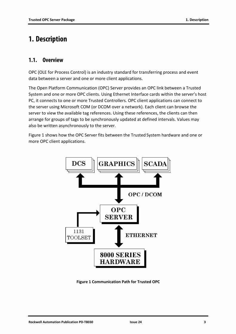
The Open Platform Communication (OPC) Server provides an OPC link between a Trusted
System and one or more OPC clients. Using Ethernet Interface cards within the server’s host PC, it connects to one or more Trusted Controllers. OPC client applications can connect to the server using Microsoft COM (or DCOM over a network). Each client can browse the server to view the available tag references. Using these references, the clients can then arrange for groups of tags to be synchronously updated at defined intervals. Values may also be written asynchronously to the server.
Figure 1 shows how the OPC Server fits between the Trusted System hardware and one or more OPC client applications.
Figure 1 Communication Path for Trusted OPC
1. Description Trusted OPC Server Package
4 Issue 24 Rockwell Automation Publication PD-T8030
1.2. Trusted OPC Architecture
The server can be divided into four main functions:
• the Browse Interface
• the OPC Data Access Interface
• the OPC Alarms & Event Interface, and
• the Communications Interface
1.2.1. The Browse Interface
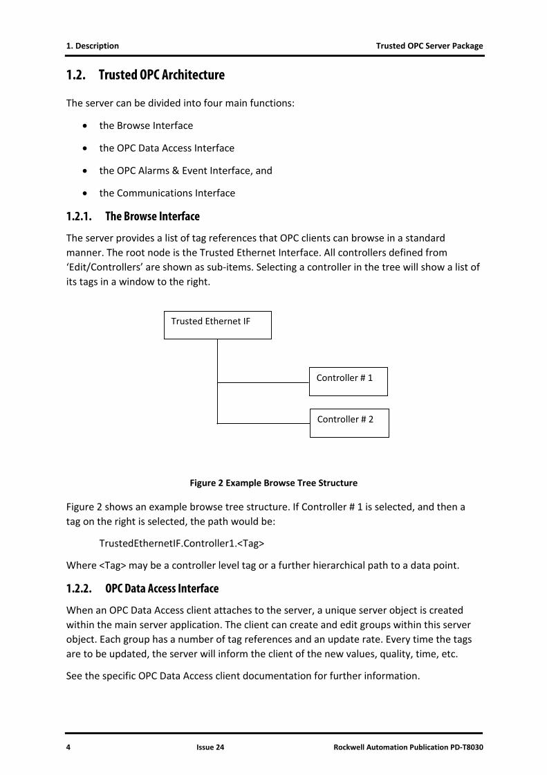
The server provides a list of tag references that OPC clients can browse in a standard manner. The root node is the Trusted Ethernet Interface. All controllers defined from ‘Edit/Controllers’ are shown as sub-items. Selecting a controller in the tree will show a list of its tags in a window to the right.
Figure 2 Example Browse Tree Structure
Figure 2 shows an example browse tree structure. If Controller # 1 is selected, and then a tag on the right is selected, the path would be:
TrustedEthernetIF.Controller1.<Tag>
Where <Tag> may be a controller level tag or a further hierarchical path to a data point.
1.2.2. OPC Data Access Interface
When an OPC Data Access client attaches to the server, a unique server object is created within the main server application. The client can create and edit groups within this server object. Each group has a number of tag references and an update rate. Every time the tags are to be updated, the server will inform the client of the new values, quality, time, etc.
See the specific OPC Data Access client documentation for further information.
Trusted Ethernet IF
Controller # 1
Controller # 2
Trusted OPC Server Package 1. Description
Rockwell Automation Publication PD-T8030 Issue 24 5
1.2.3. OPC Alarm & Event Interface
When an OPC Alarm & Event client attaches to the server, a unique server object is created within the main server application. Each time an event occurs, the server informs the client of the event. Event information includes the tag name, value, time the event occurred, etc.
See the specific OPC Alarm & Event client documentation for further information.
1.2.4. OPC Data Access vs. OPC Alarm & Event
OPC Data Access and OPC Alarm & Event clients are based on separate OPC standards. While some OPC clients support both standards within the same package, most OPC clients will support one or the other. OPC Data Access clients are the most common, and are used by many Man Machine Interface (MMI) packages to monitor specific process variables originating from a Trusted system. OPC Alarm & Event clients are used primarily in “Event Historian” or “Event Log” type applications.
OPC Data Access clients query the server by tag name. They can query the value of a specific tag, create groups of tags which will be updated at regular intervals, subscribe to a tag to receive updates when that tag’s value changes, or change the value of the tag in the Trusted controller. The server allows Data Access clients to access any Controller tag that either has a communications address or is configured for Sequence of Event or Process Historian updates.
OPC Alarm & Event clients query the server by controller name. Instead of being able to query by tag name, the OPC Alarm & Event clients receive all events originating from subscribed controllers. The server will generate events only for tags defined by a Controller that are configured for Sequence of Event updates.
1.2.5. Communications Interface
The server manages all OPC client queries, updates, polling groups, and subscriptions. The server translates these requests into a combination of both polled and event updates, which are sent to the appropriate Trusted controller. As is the intention of the OPC standards, the OPC clients do not know about or need to understand the specific communication details between the server and the Controllers.

1. Description Trusted OPC Server Package
6 Issue 24 Rockwell Automation Publication PD-T8030
Page intentionally left blank
Trusted OPC Server Package 2. Installation and Configuration
Rockwell Automation Publication PD-T8030 Issue 24 7
2. Installation and Configuration
2.1. ‘Log on as a Service’ Privilege
The server runs as a Windows service. This means that it has no application window, it does not appear on the taskbar and it cannot be started using an icon. However, it is able to run even when no users have logged in and can automatically start on boot up without needing a user to log in.
Before installing the OPC Server, a user may be given privilege to start an application as a service. Choose a user with Administrator privileges. If the service is to start in the local system account, then a separate privileged user is not required.
Versions of the OPC Server before 102 operate as executable programs within the user login, and do not need a service privilege. Starting and stopping these versions requires the program to be stopped and restarted. The configuration functions described here are available from the server program itself.
2.1.1. Windows 2000 and XP
1. Click Start | (and Settings on 2000) Control Panel | Administrative Tools | Local Security Policy.
2. In XP, Administrative Tools may also appear on the Start menu, or may have been disabled. To enable this, right click on Start and select Properties. In the Start Menu tab, click Customize. In the Advanced tab, scroll down the Start menu items to the bottom and select to display System Administrative Tools.
3. If the Control Panel is arranged in categories, in the Control Panel Pick a category view, select Performance and Maintenance and then Administrative Tools. Select Local Security Policy.
4. In Local Security Settings, select Local Policies. Select User Rights Assignment. Double-click on Log on as a service. The Properties window shows the users that are allowed to start a service.
5. If the chosen user does not appear in the list, add the user by clicking Add (2000) or Add user or group (XP). In XP, clicking Advanced and Find Now displays all available users.
2.2. Installing the OPC Server
The Trusted OPC Server must be installed and configured before OPC clients can use it. Installation is accomplished by running the setup program on the installation CD, which will run automatically if Autoplay is enabled.
2. Installation and Configuration Trusted OPC Server Package
8 Issue 24 Rockwell Automation Publication PD-T8030
In addition to the OPC Server, the setup program will install a number of files required for OPC. The setup program also updates the registry to allow OPC clients to browse for and connect to the server.
Windows versions NT, 2000 and XP require administrator privileges in order to complete the installation. Windows NT installations require Service Pack 4 or higher. Basic configuration consists of telling the OPC Server which Controller to connect to, where to find its symbol database, and how fast to poll the controller for updates.
The installation program offers the option of a full installation, which includes the OPC Server, and ‘Remote Configuration Program Only’, which only provides the configuration tool and not the OPC Server.
The installation program allows a specific username to be used to run the service. If the service is to run under the local system account, there is no need to enter a user and password. If a specific user is required and was given the privilege in section 2.1, enter the username and password.
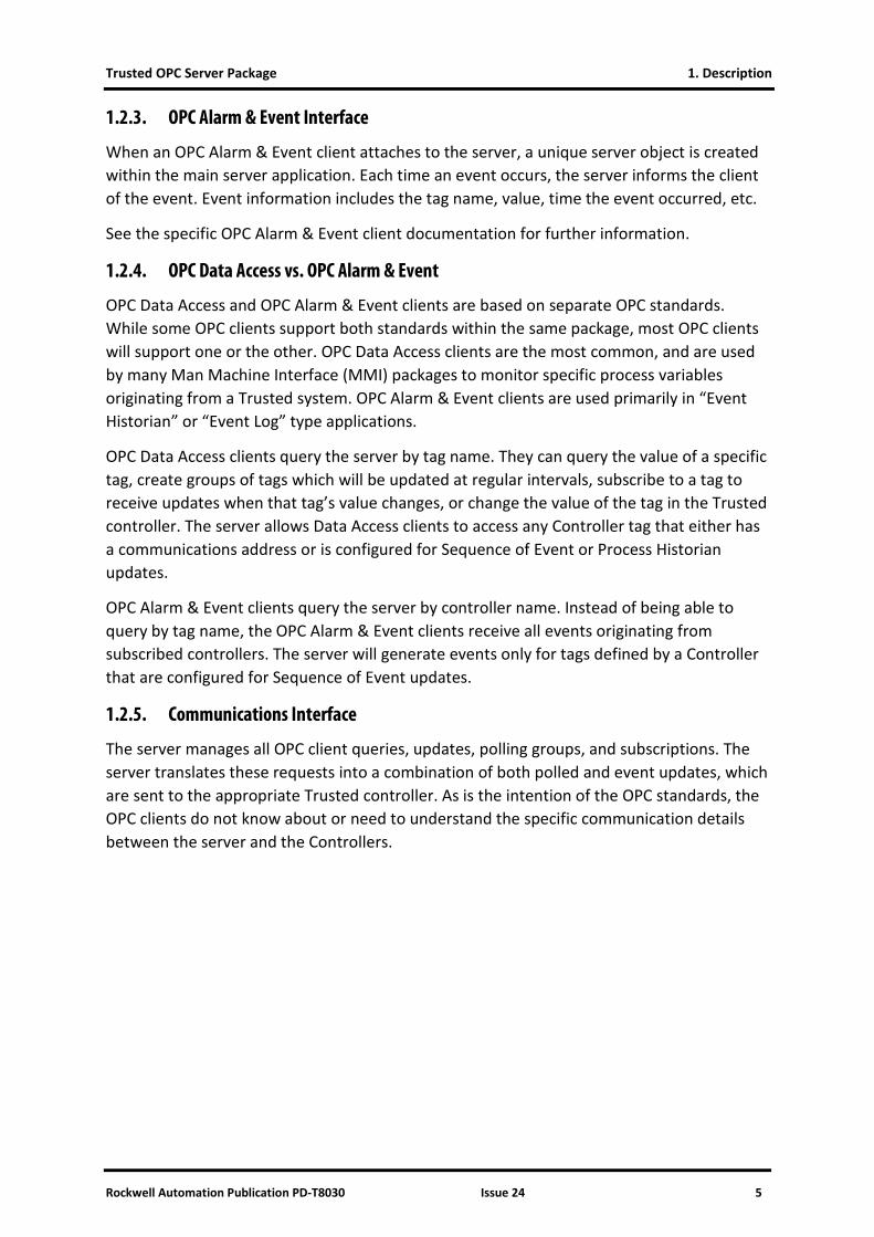
The installation will ask for the serial number supplied with the package on a label, as shown in Figure 3. Enter the serial number and attach the label to the PC on which the OPC Server is installed.
Figure 3 Serial Number Entry
Trusted OPC Server Package 2. Installation and Configuration
Rockwell Automation Publication PD-T8030 Issue 24 9
2.3. Running the Server Application
The server will start automatically when a client requests a connection, or automatically on boot up. However, the following paragraphs explain how to start, stop or restart the server if necessary.
2.3.1. Windows 2000 and XP
The Windows services may be configured using a Windows utility called the Services Management Console. To run this utility, select Administrative Tools as in section 2.1.1. Select Services.
The Services management console displays a list of all available Windows services. Windows has many services, active and inactive. Scroll down the list on the right until TrustedOPCServer is visible.
Each service operates under the rights of either the local system account or a specified account. The account can be changed from the Properties of TrustedOPCServer. Right-click on TrustedOPCServer and select Properties, or double click. Select the Log On tab.
If a user account is required, select This Account and enter the name of an administrator user. It may be necessary to enter the workgroup name and a ‘\’ before the username. It is possible to browse for all available users using the Browse button (and then Advanced in XP). Enter the password twice. If successful and the user did not previously have service rights, these rights will be assigned. Close the Properties window.
To run the service, select Start the Service from the Services program. If the user login username and password were correct, the service will be started. The user is then able to stop or restart the service.
The service can also be started and stopped using a command in the Command Prompt window:
sc start trustedopcserver
sc stop trustedopcserver
sc query trustedopcserver (reports if the service is running).
The following commands can be used manually from a Command Prompt window called directly by a program, or included in a batch file.
c:\Trusted\OPC\OPCServer.exe /start
c:\Trusted\OPC\OPCServer.exe /stop
These will display a pop-up box indicating that the server has been stopped or started. To suppress the pop-up box add the command line option ’/Q‘ to the end of the command line, e.g.
C:\Trusted\OPC\OPCServer.exe /stop /Q
2. Installation and Configuration Trusted OPC Server Package
10 Issue 24 Rockwell Automation Publication PD-T8030
The server will also start automatically if an OPC client attempts to connect to the server. There is therefore no need to manually start the server.
The service is also visible in the Windows Task Manager as OPCServer.exe in the Processes tab.
2.4. Configuring the OPC Server
Since the server runs as a Windows service it has no direct user interface. A separate program OPCServerConfig, supplied with the installation, allows the user to configure the server. This program is installed in the same directory as the OPC, e.g. Trusted/OPC.
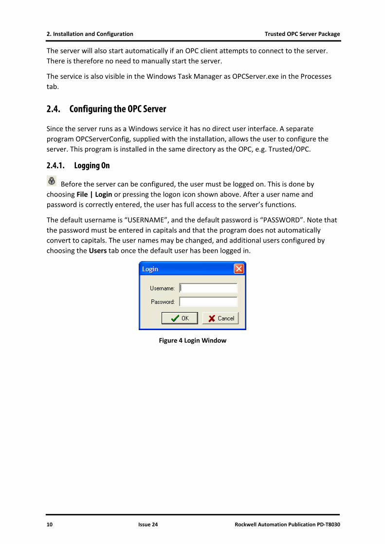
2.4.1. Logging On
Before the server can be configured, the user must be logged on. This is done by choosing File | Login or pressing the logon icon shown above. After a user name and password is correctly entered, the user has full access to the server’s functions.
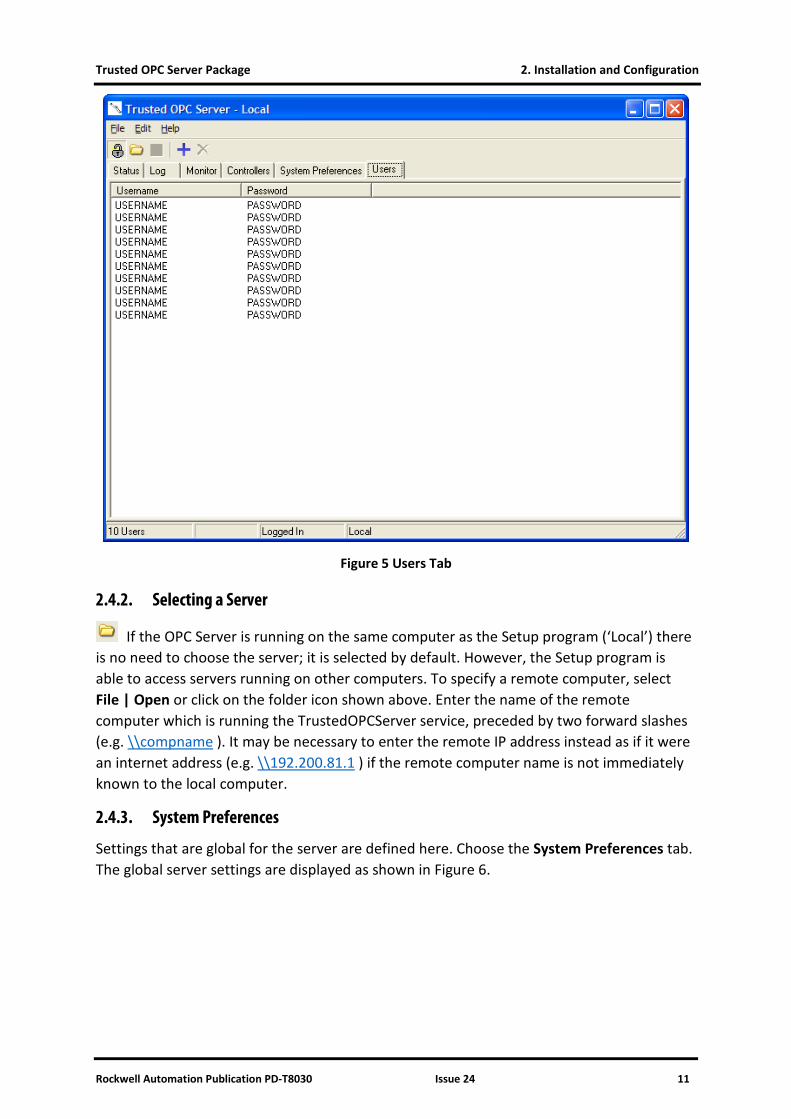
The default username is “USERNAME”, and the default password is “PASSWORD”. Note that the password must be entered in capitals and that the program does not automatically convert to capitals. The user names may be changed, and additional users configured by choosing the Users tab once the default user has been logged in.
Figure 4 Login Window
Trusted OPC Server Package 2. Installation and Configuration
Rockwell Automation Publication PD-T8030 Issue 24 11
Figure 5 Users Tab
2.4.2. Selecting a Server
If the OPC Server is running on the same computer as the Setup program (‘Local’) there is no need to choose the server; it is selected by default. However, the Setup program is able to access servers running on other computers. To specify a remote computer, select File | Open or click on the folder icon shown above. Enter the name of the remote computer which is running the TrustedOPCServer service, preceded by two forward slashes (e.g. \\compname ). It may be necessary to enter the remote IP address instead as if it were an internet address (e.g. \\192.200.81.1 ) if the remote computer name is not immediately known to the local computer.
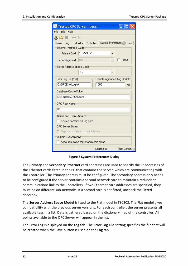
2.4.3. System Preferences
Settings that are global for the server are defined here. Choose the System Preferences tab. The global server settings are displayed as shown in Figure 6.
2. Installation and Configuration Trusted OPC Server Package
12 Issue 24 Rockwell Automation Publication PD-T8030
Figure 6 System Preferences Dialog
The Primary and Secondary Ethernet card addresses are used to specify the IP addresses of the Ethernet cards fitted in the PC that contains the server, which are communicating with the Controller. The Primary address must be configured. The secondary address only needs to be configured if the server contains a second network card to maintain a redundant communications link to the Controllers. If two Ethernet card addresses are specified, they must be on different sub-networks. If a second card is not fitted, uncheck the Fitted checkbox.
The Server Address Space Model is fixed to the Flat model in T8030S. The Flat model gives compatibility with the previous server versions. For each controller, the server presents all available tags in a list. Data is gathered based on the dictionary map of the controller. All points available to the OPC Server will appear in the list.
The Error Log is displayed on the Log tab. The Error Log File setting specifies the file that will be created when the Save button is used on the Log tab.
Trusted OPC Server Package 2. Installation and Configuration
Rockwell Automation Publication PD-T8030 Issue 24 13
The Global Ungrouped Tag Update setting defines the frequency that tags will be read from the Trusted Controller that are not configured for SOE or Process Historian and do not have a valid group or update rate specified. Where OPC clients create OPC groups that contain an update rate, that update rate will be used. Some OPC Clients do not create OPC groups, or they create groups that have an update rate of zero. In these situations, the Global Ungrouped Tag Update setting will be used. More information on the OPC timing settings is given in Section 2.4.5 Server Timing.
The Database Cache Folder stores the server’s copy of the state of all OPC data. This is normally stored in the OPC program directory as above but may be moved if required.
The OPC Root Name is the left hand end of the OPC tag names as reported to clients. Thus, in the following example, the tag names will be presented as:
TrustedEthernetIF.<controller>.<tagname>
The OPC Root Name is TrustedEthernetIF.
The Alarms and Events Source - Source contains full tag path checkbox specifies if the source field in an Alarms and Events event should contain the full tag path which includes the controller name, or should only contain the tag name. When the checkbox is checked, the full tag path will be included in the events.
Some OPC clients add a subscription for each instance of a tag that they are using, and remove the subscriptions relating to instances that are no longer used. By default, the OPC server enables data updates when a subscription is added, but cancels data updates when a subscription is removed, with no counting of active subscriptions per tag. Therefore data updates are lost when the OPC client removes a subscription, even if it had another active subscription to that tag. To allow compatibility with these clients, a new option has been added in CD build 108. If the Multiple Subscriptions - Allow from same server and same group checkbox is checked, the OPC server will count subscriptions to each tag and only cancel data updates when the last subscription is removed. If the option is not checked, the OPC server will cancel data updates on any subscription removal (as required for most OPC clients).
Another new option in CD build 108 is visible but greyed out on the 8030 OPC server. The OPC Server Status option is only available in P8032 OPC server.
If any of the settings for the server are changed, the settings must be saved and the server must be restarted. To save the settings, click the disk icon (shown left) or select File | Save. On saving a change, the configuration tool reminds the user that changes to settings will not take effect until the server is restarted. Refer to section 2.3 above for the methods available to restart the server. Note that some clients will then also need to be restarted in order to be updated.
2. Installation and Configuration Trusted OPC Server Package
14 Issue 24 Rockwell Automation Publication PD-T8030
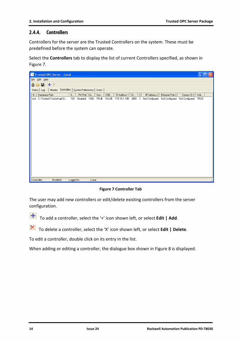
2.4.4. Controllers
Controllers for the server are the Trusted Controllers on the system. These must be predefined before the system can operate.
Select the Controllers tab to display the list of current Controllers specified, as shown in Figure 7.
Figure 7 Controller Tab
The user may add new controllers or edit/delete existing controllers from the server configuration.
To add a controller, select the ‘+’ icon shown left, or select Edit | Add.
To delete a controller, select the ‘X’ icon shown left, or select Edit | Delete.
To edit a controller, double click on its entry in the list.
When adding or editing a controller, the dialogue box shown in Figure 8 is displayed.
Trusted OPC Server Package 2. Installation and Configuration
Rockwell Automation Publication PD-T8030 Issue 24 15
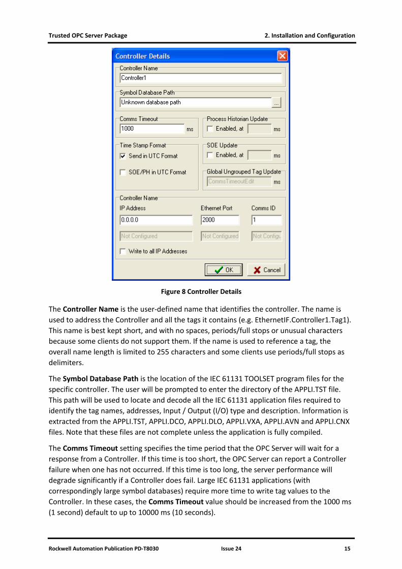
Figure 8 Controller Details
The Controller Name is the user-defined name that identifies the controller. The name is used to address the Controller and all the tags it contains (e.g. EthernetIF.Controller1.Tag1). This name is best kept short, and with no spaces, periods/full stops or unusual characters because some clients do not support them. If the name is used to reference a tag, the overall name length is limited to 255 characters and some clients use periods/full stops as delimiters.
The Symbol Database Path is the location of the IEC 61131 TOOLSET program files for the specific controller. The user will be prompted to enter the directory of the APPLI.TST file. This path will be used to locate and decode all the IEC 61131 application files required to identify the tag names, addresses, Input / Output (I/O) type and description. Information is extracted from the APPLI.TST, APPLI.DCO, APPLI.DLO, APPLI.VXA, APPLI.AVN and APPLI.CNX files. Note that these files are not complete unless the application is fully compiled.
The Comms Timeout setting specifies the time period that the OPC Server will wait for a response from a Controller. If this time is too short, the OPC Server can report a Controller failure when one has not occurred. If this time is too long, the server performance will degrade significantly if a Controller does fail. Large IEC 61131 applications (with correspondingly large symbol databases) require more time to write tag values to the Controller. In these cases, the Comms Timeout value should be increased from the 1000 ms (1 second) default to up to 10000 ms (10 seconds).
2. Installation and Configuration Trusted OPC Server Package
16 Issue 24 Rockwell Automation Publication PD-T8030
The OPC standard specifies that all time-stamp information use the UTC time zone (which is the same as the GMT time zone). When the Time Stamp Format has Send in UTC Format option enabled, the server will convert time-stamp information from the local time zone to UTC before it is presented to clients. The OPC client should then convert the time-stamp information back to local before it is displayed or logged. For OPC clients that do not perform the UTC to local time zone conversion, the Send in UTC Format checkbox should be disabled.
The timestamps generated for Sequence of Events and Process Historian changes are based on the time in the Trusted Controller. Normally the Controller clock is set to local time, but if necessary it can be set to UTC. If the Controller clock is set to UTC, the SOE/PH in UTC Format checkbox must be checked. If the Controller clock is set to local time the SOE/PH in UTC Format checkbox must be unchecked.
Process Historian and Sequence of Events data can both be enabled/disabled and given individual update rates. Sequence of Events or Process Historian polling can be enabled (with no ill effects) even when Sequence of Events and/or Process Historian is not configured for the controller. When enabled, a refresh rate of 500 ms to 2000 ms is appropriate. The Process Historian contains time stamped changes to analogue variables that have been configured for Process Historian collection in the Trusted application. The SOE contains time stamped changes to Boolean and some small value analogue variables (usually channel status variables, ranged 0 to 7) that have been configured for SOE collection.
The Global Ungrouped Tag Update Rate setting specifies the poll rate of any tags that do not have an update rate specified by the OPC client. It can only be set in the System Preferences tab, and applies to all Controllers.
None of the update rates may be less than 10 ms. Typical values for the update rate range from 100 ms to 500 ms. More information on the OPC timing settings is given in Section 2.4.5, Server Timing.
Two Ethernet connections can be configured. Each consists of an IP Address, an Ethernet Port number and a Comms ID number.
The IP Address specifies the addresses of the Communication Interface modules (T8151B) installed in the Controller. In the case where a redundant Ethernet link is configured, the sub-network of each card must be different. The first IP Address must be on the same Ethernet sub-network as the Primary Ethernet Interface Card (see section 2.4.3, System Preferences). The second IP Address must be on the same Ethernet sub-network as the Secondary Ethernet Interface Card. If only one Ethernet card is fitted, only the first IP Address should be specified. See section 4 Suggested Network Configurations, for details of IP networks and addresses.
The Ethernet port numbers specify the Ethernet port that the server will connect to on the Controller. This is usually set to 2000 but must be included in the System Configuration.
Trusted OPC Server Package 2. Installation and Configuration
Rockwell Automation Publication PD-T8030 Issue 24 17
The Comms ID number specifies the node address to use when communicating with the controller. It must match the slave ID responded to by the Modbus Slave set up in the controller’s Communication Interface modules.
The final checkbox, Write to all IP addresses, is included for completeness and compatibility. On dual systems, data is read from only one of the two controller halves. However, data must be written to both halves simultaneously. This does not apply to Trusted Controllers. This checkbox should be unchecked.
Having added/deleted or changed the Controller settings, the configuration must be downloaded to the server and the server must be restarted. To save the settings, click the disk icon (shown above left) or select File | Save. On saving a change, the config tool reminds the user that changes to settings will not take effect until the server is restarted. Refer to section 2.3 above for the methods available to restart the server. Note that some clients will then also need to be restarted in order to be updated.
2.4.5. Server Timing Settings
The best settings for the OPC poll rates (Global Ungrouped Tag Update, Process Historian Update and Sequence of Events Update), are entirely dependent on the configuration of the system. They should be set to allow sufficient time for all communications to occur.
The OPC Server is capable of performing approximately 40 messages per second. This is the total number of messages to all controllers, so one controller would be addressed 40 times, four controllers would be addressed 10 times.
A single SOE or Process Historian poll takes four separate messages, so at best the OPC Server can do 10 SOE or Process Historian polls per second.
The following information is required to determine the best poll rates:
• The number of controllers that the OPC Server connects to.
• The number of Boolean and analogue points per controller that are read directly (no SOE or Process Historian), their communications addresses, and the update rate required. Calculate how many messages are required to read the full map for all controllers (defined as NO below). A single message can read approximately 900 Booleans or 125 16-bit analogues, provided the addresses are contiguous.
• The number of Boolean and analogue points per controller that are polled via SOE or Process Historian, and how often they change state. Each SOE or Process Historian poll can read a maximum of twelve changes. If there are a large number of changes to be read regularly, the SOE or Process Historian data would need to be read more frequently to prevent a build-up of changes in the controller. Calculate how often the event data must be polled.
Given the number of ordinary messages NO and the required ungrouped tag update rate for this non-event data, calculate the messages needed per second required to keep up with the desired rate.
2. Installation and Configuration Trusted OPC Server Package
18 Issue 24 Rockwell Automation Publication PD-T8030
PO1 = NO / Ungrouped Tag Update Rate (in seconds)
Since the OPC Server can perform approximately 40 messages per second, and an event poll takes four messages, the messages per second remaining for event driven data are:
PE1 = (40 – PO1) / 4
If CS is the number of controllers needing SOE polls, CPH is the number of controllers needing Process Historian polls, the SOE and Process Historian minimum poll rate in milliseconds (to ensure all event buffers get at least one poll) is:
1000 x (CS + CPH) PE1
Some System Control And Data Acquisition (SCADA) OPC clients can be configured to only request the points that are currently on screen. This reduces the number of ordinary messages required, but is entirely dependent on the configuration of the graphics layout.
Using a low bandwidth connection (e.g. radio link, multiplexed fibre connection) will reduce the number of messages per second.
The number of ordinary messages is often too complex to calculate with any precision. Normally the easiest way to set up the poll rates is to set the Ungrouped Tag Update Rate (global poll rate) to the slowest acceptable update rate. Then set the SOE and Process Historian poll rates as fast as possible, but without overloading the communications link.
Examples:
All Tags collected by Sequence of Events and/or Process Historian
Global Ungrouped Tag Update - Should be set to a high value (e.g. 10000 ms (10 seconds)) so that accidentally configuring a non-SOE/PH Tag in the future will not compromise the server communication link.
Process Historian Update and Sequence of Events Update - The combined poll rate should not exceed 12 polls per second. If both are used they should be set to 166 ms or higher, if only one is used it should be set to 83 ms or higher and the other should be unchecked.
No Tags collected by Sequence of Events or Process Historian
Global Ungrouped Tag Update - Set to the required update rate. The server will attempt to refresh all ungrouped tags at this rate, provided it is less than the maximum achievable transfer rate. The maximum transfer rate achievable per second is approximately 5000 16-bit Analogue variables, or 2500 32-bit Analogue variables, or 35000 Boolean variables. This requires all the variables to be configured with consecutive communications addresses. Any other configurations of communications addresses or combinations of the data types will affect the maximum achievable transfer rates. Setting the rate to 1000 ms (1 second) would allow this number of variables to be read, setting the rate to 2000 ms (2 seconds) would allow double this number of variables to be read.
Trusted OPC Server Package 2. Installation and Configuration
Rockwell Automation Publication PD-T8030 Issue 24 19
Process Historian Update and Sequence of Events Update - These should be unchecked for this example.
Only Some Tags collected by SOE / Process Historian
As the normal polling and SOE/PH polling share the bandwidth, the poll rates for both have to be reduced. The best polls rates can only be determined by tuning the poll rates with the final databases.
Typically in one second it is possible to do three SOE polls, three Process Historian polls, and have sufficient bandwidth available to read approximately 2500 16-bit Analogue variables, or 1250 32-bit Analogue variables, or 17500 Boolean variables (assuming that they have consecutive communications addresses).
2.4.6. Users
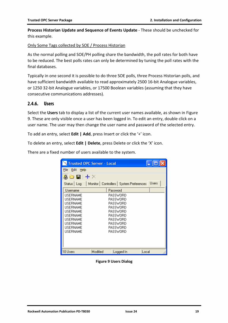
Select the Users tab to display a list of the current user names available, as shown in Figure 9. These are only visible once a user has been logged in. To edit an entry, double click on a user name. The user may then change the user name and password of the selected entry.
To add an entry, select Edit | Add, press Insert or click the ‘+’ icon.
To delete an entry, select Edit | Delete, press Delete or click the ‘X’ icon.
There are a fixed number of users available to the system.
Figure 9 Users Dialog
2. Installation and Configuration Trusted OPC Server Package
20 Issue 24 Rockwell Automation Publication PD-T8030
2.5. Configuring the Trusted Controller
2.5.1. Trusted Communication Interface Modules
In order for the OPC Server to communicate with a Controller, one or more Communication Interface modules must be configured. In addition to defining the IP addresses that are used in the Controller Details dialog, a Modbus slave must be configured. The Slave Address must be set to the same value as the Comms ID Number defined in the Controller Details dialog. Communications should be set to “Wait TCP/IP Connection” for port 2000. Please see the Product Description PD-T8151B for the Communication Interface for further configuration details.
In the Controller system configuration, the Communication Interface Connection Timeout is used to determine if an Ethernet link has failed. If the Trusted Communication Interface module has an open Ethernet connection that has not sent or received any data for this period, the Ethernet connection will be closed. This ensures that any Ethernet connection that has failed is released so that it can be re-used. The value should be considerably larger than the other timeouts. A value of 300 seconds (5 minutes) is usually suitable.
2.5.2. Real-time Clock
The date and time settings for the Controller should be synchronised with the date and time of the PC hosting the OPC Server application.
2.6. Configuring the IEC 61131 Application
2.6.1. Update Types
The OPC Server receives tag updates from a Controller using two methods: polled updates or Sequence of Events / Process Historian updates (event updates).
• A polled update is when the OPC Server pulls the value of a tag from the controller through an update request. The value of the tag is its value at the time the update request is made, and the time-stamp associated with a change is provided by the OPC Server at the time that the update request is received.
• An event update is when the Controller pushes the value of a tag to the OPC Server whenever its value changes. Tag values are queued by the Controller before being sent to the OPC Server, and are supplied in the order in which they were recorded by the controller. Unlike polled updates, the time-stamp associated with an event update comes from the Controller. For certain tags associated with Trusted High Density I/O modules, the time-stamp comes directly from the I/O module.
2.6.2. Tag Configuration
In order to retrieve the value of a tag through a polled update, the tag must be given a communications address. In order to retrieve the value of a tag through an event update, the tag must have the “Enable SOE Logging” attribute set.
Trusted OPC Server Package 2. Installation and Configuration
Rockwell Automation Publication PD-T8030 Issue 24 21
Only Boolean tags with the “Enable SOE Logging” attribute or tags that are connected to a special SOE I/O board will be reported to OPC Alarm & Event clients. The defined TRUE/FALSE value strings for each tag will be used when reporting events. If no TRUE/FALSE value strings are defined, the events will be reported as “TRUE” or “FALSE”.
Details of how to set Extended Attributes, define TRUE/FALSE value strings and connect variables to SOE or Process Historian boards can be found in the Product Description PD-8013 SOE & Process Historian Software Package.
Whenever the application dictionary is changed, the OPC Server controller database must be reloaded from the new Toolset files as described in section 2.4.4 Controllers.
2.6.3. Read/Write Timing
If a client reads and writes the same point, and the point is assigned a Modbus address but is not assigned to SOE, then on writing a new value, the old value may be briefly read back before the new written value reflects from the system. This may appear, for example, as True, False, True on writing a Boolean to True. This is because the OPC server stores its own copy of the written value and reports it back to the client, but will not immediately write it to the system via a Modbus write until the next scheduled write. A subsequent read request may arrive at the system first and return the old value. This problem occurs on any polled data communications protocol with an intermediate buffer.
There are two ways to eliminate the problem:
• Do not read the same value that is used for writing. If an acknowledgement is required that a value written has been received by the system, copy the value in the system application to a different variable and change the OPC client to read from this second variable.
• Turn SOE on for the variable being written. This will prevent the OPC server reading the value via Modbus, therefore no intermediate value will be seen.
2.7. Reserved Variables
The OPC Server provides summary data on each Controller.
The tagnames below are built in the following format:
<Rootname> The name of the server, as configured in the System Preferences tab (OPC Root name). By default this is TrustedEthernetIF.
<controller> The name of the controller, as configured in the Controllers tab. By default these are Controller0, Controller1, Controller2 etc.
2.7.1. Controller Information
The following OPC tags are automatically available at the Controller level.
<Rootname>.<controller>._OPC_COMMS_FAILURE_1
2. Installation and Configuration Trusted OPC Server Package
22 Issue 24 Rockwell Automation Publication PD-T8030
(and _OPC_COMMS_FAILURE_2 if two communications ports were defined)
This is used to indicate the status of the controller to server connection. ‘Off’ indicates that the connection is working, and ‘On’ indicates a failure. Type: Boolean.
<Rootname>.<controller>._OPC_SERVER_HEARTBEAT_
This is a counter that changes from 0 to 59 at a rate of one change per second. This can be used to periodically ensure that the server is still functioning correctly. Type: Integer.
2.8. Configuring the PC
2.8.1. Real-time Clock
The date and time settings for the Trusted controller should be synchronised with date and time of the PC hosting the OPC Server application. The PC’s time zone should be set to the local time zone.
2.9. Configuring the OPC Client
2.9.1. Connecting to the Server
Connecting to the server is implemented differently for each OPC client. For those OPC clients that allow browsing of the available OPC servers, the OPC Server is identified as ICSTriplex.Trusted.1 for OPC Data Access clients and ICSTriplex.Event.1 for OPC Alarm & Event clients. Refer to the specific OPC client documentation for further details.
The comment/description field from the Toolset application is delivered to the OPC client for each point. This field appears in the OPC ‘Attributes’ fields and is usually accessible in the client in the Point Properties data.
2.9.2. Point Quality Initialisation
The point quality status data is initialised differently according to the method of data access.
If a point is configured for polled update, i.e. with a Modbus address only, on initialisation of the OPC data the quality will be displayed as ‘Good’. Subsequent changes will be time-stamped from the PC running the OPC server.
If a point is configured for event update (SOE only), on initialisation of the OPC data the quality will be displayed as ‘Bad’ until a point event (due to a change of state) occurs. Events will be time-stamped with the event timestamp.
If a point is configured with a Modbus address and also has an SOE attribute, on initialisation of the OPC data the quality will be displayed as ‘Good’. Subsequent changes will be time-stamped from the PC running the OPC server.

Trusted OPC Server Package 2. Installation and Configuration
Rockwell Automation Publication PD-T8030 Issue 24 23
Page intentionally left blank
Trusted OPC Server Package 3. Operation
Rockwell Automation Publication PD-T8030 Issue 24 24
3. Operation
3.1. Communication with the Trusted Controller
When the OPC Server is configured and running, it will begin communicating with the defined controller(s). At a minimum, the server will poll all of the defined communication ports to ensure that they are available. If Sequence of Events or Process Historian updates have been enabled, the server will begin communicating with the controller to receive those updates. Polled updates will only occur once an OPC client has connected to the server and subscribed to individual tags.
The normal operation of the server is to attempt to communicate to a controller through the defined primary port, while occasionally verifying the communication path through the secondary port if one is defined. Errors in communicating through the primary port will cause the server to switch to the secondary port if one is available.
3.2. Monitoring the OPC Server
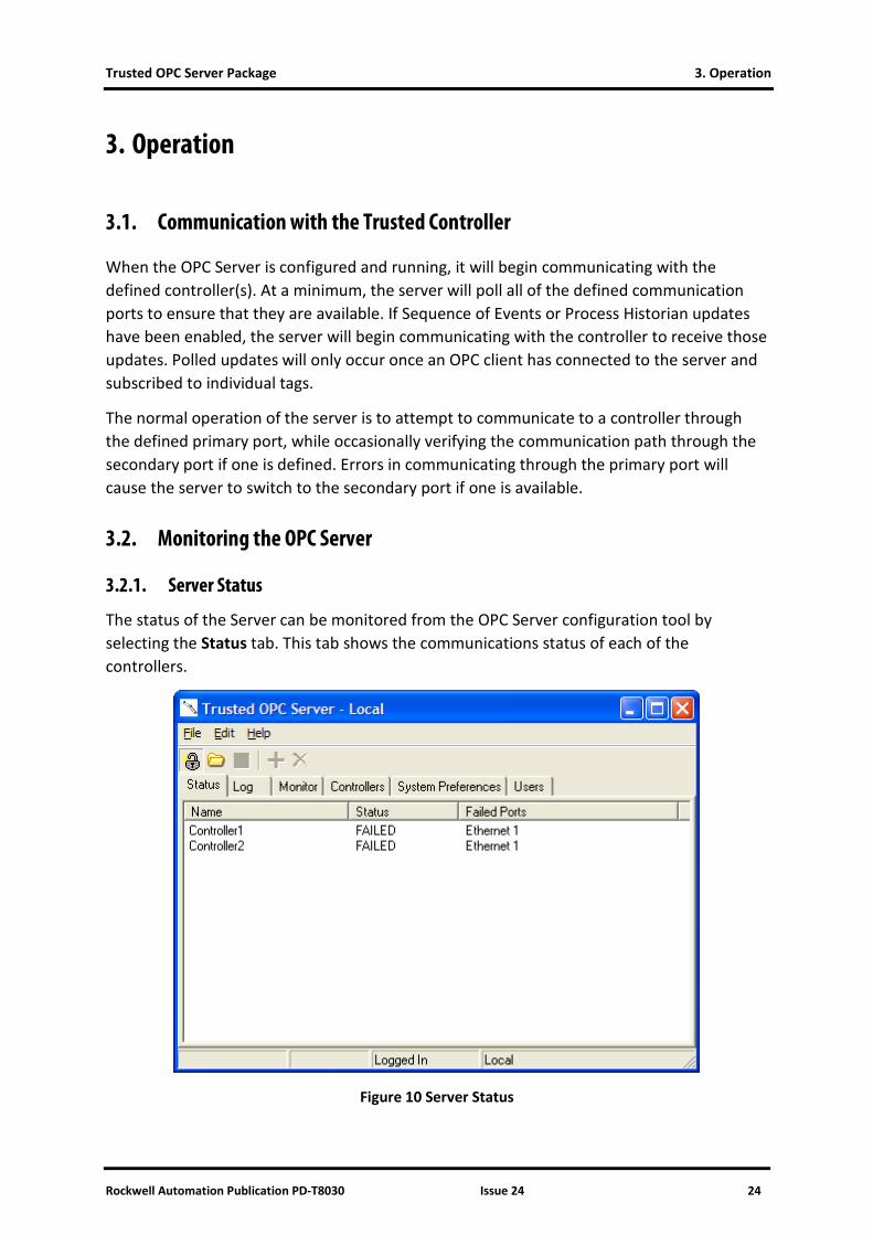
3.2.1. Server Status
The status of the Server can be monitored from the OPC Server configuration tool by selecting the Status tab. This tab shows the communications status of each of the controllers.
Figure 10 Server Status
Trusted OPC Server Package 3. Operation
Rockwell Automation Publication PD-T8030 Issue 24 25
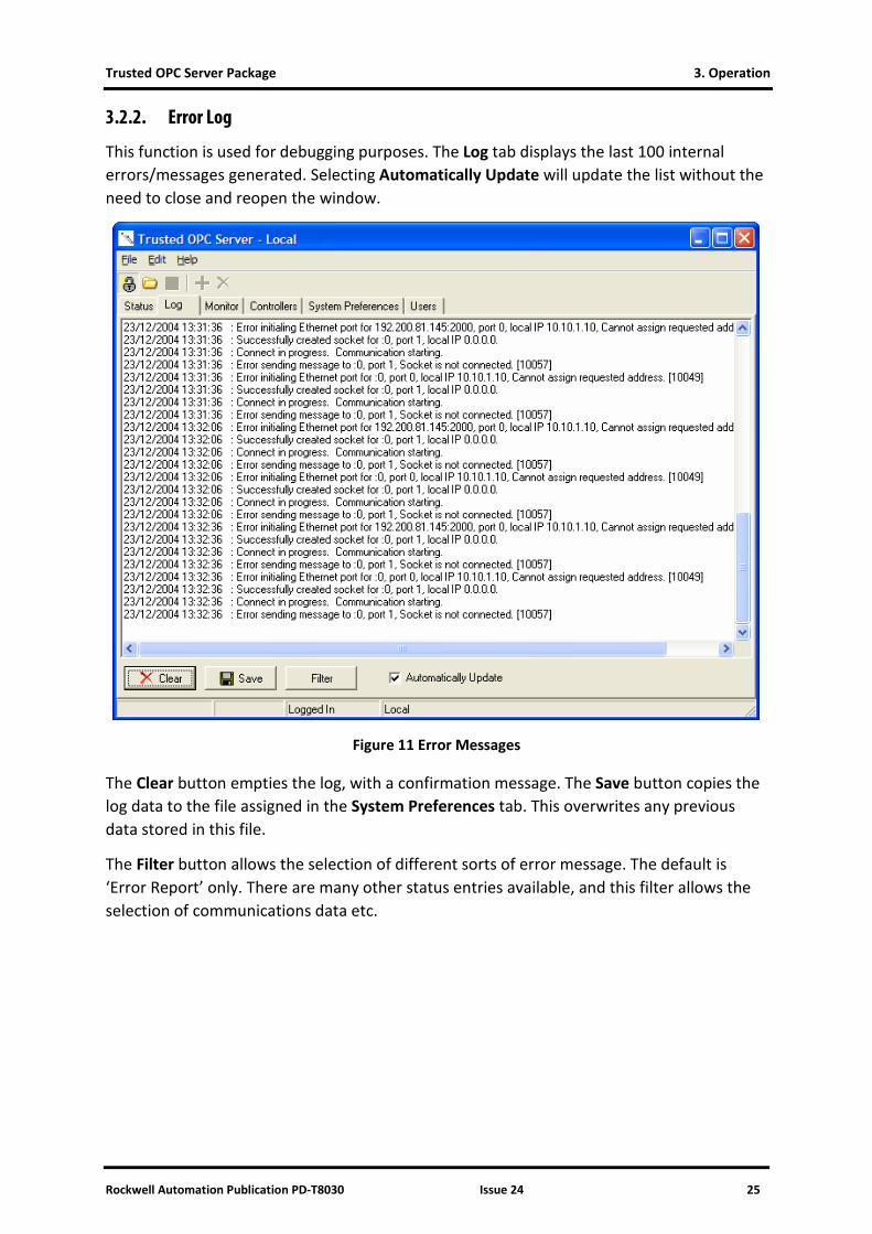
3.2.2. Error Log
This function is used for debugging purposes. The Log tab displays the last 100 internal errors/messages generated. Selecting Automatically Update will update the list without the need to close and reopen the window.
Figure 11 Error Messages
The Clear button empties the log, with a confirmation message. The Save button copies the log data to the file assigned in the System Preferences tab. This overwrites any previous data stored in this file.
The Filter button allows the selection of different sorts of error message. The default is ‘Error Report’ only. There are many other status entries available, and this filter allows the selection of communications data etc.
3. Operation Trusted OPC Server Package
26 Issue 24 Rockwell Automation Publication PD-T8030
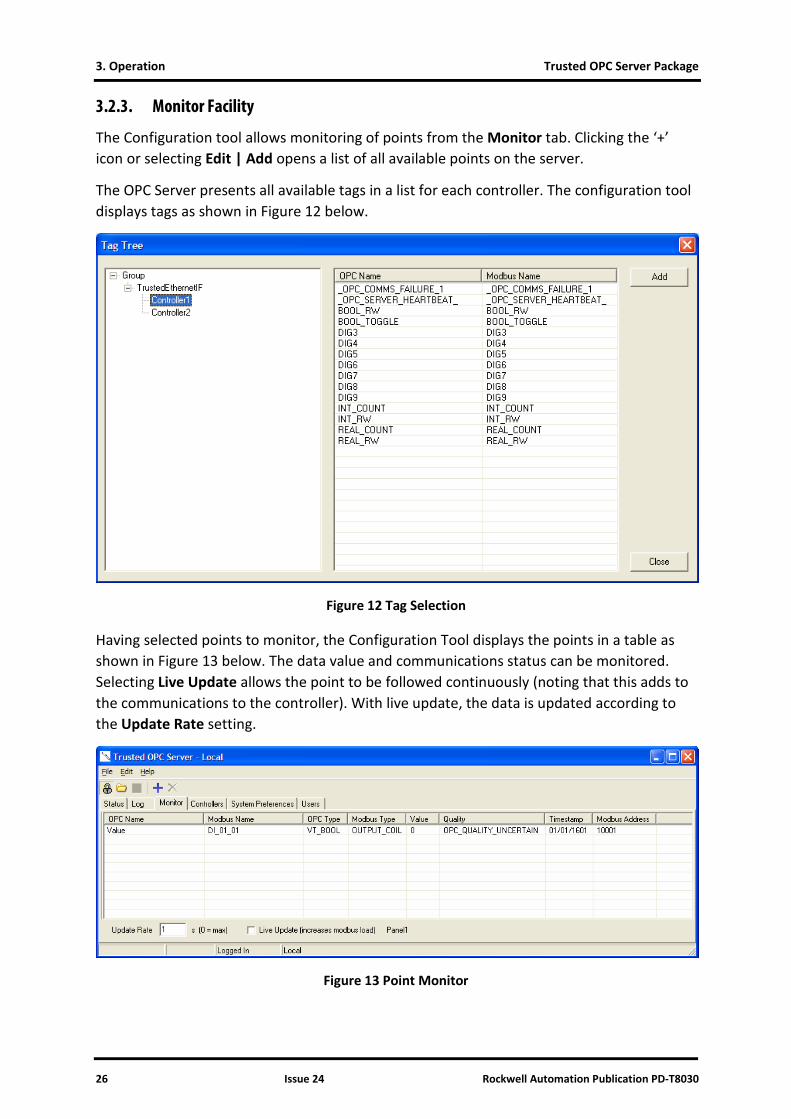
3.2.3. Monitor Facility
The Configuration tool allows monitoring of points from the Monitor tab. Clicking the ‘+’ icon or selecting Edit | Add opens a list of all available points on the server.
The OPC Server presents all available tags in a list for each controller. The configuration tool displays tags as shown in Figure 12 below.
Figure 12 Tag Selection
Having selected points to monitor, the Configuration Tool displays the points in a table as shown in Figure 13 below. The data value and communications status can be monitored. Selecting Live Update allows the point to be followed continuously (noting that this adds to the communications to the controller). With live update, the data is updated according to the Update Rate setting.
Figure 13 Point Monitor

Trusted OPC Server Package 3. Operation
Rockwell Automation Publication PD-T8030 Issue 24 27
Page intentionally left blank
Trusted OPC Server Package 4. Suggested Network Configurations
Rockwell Automation Publication PD-T8030 Issue 24 28
4. Suggested Network Configurations
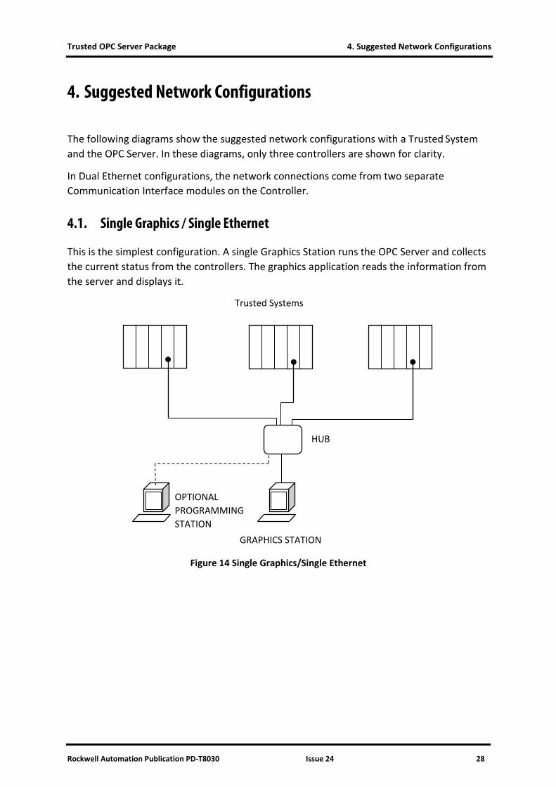
The following diagrams show the suggested network configurations with a Trusted System and the OPC Server. In these diagrams, only three controllers are shown for clarity.
In Dual Ethernet configurations, the network connections come from two separate Communication Interface modules on the Controller.
4.1. Single Graphics / Single Ethernet
This is the simplest configuration. A single Graphics Station runs the OPC Server and collects the current status from the controllers. The graphics application reads the information from the server and displays it.
Figure 14 Single Graphics/Single Ethernet
OPTIONAL PROGRAMMING STATION
HUB
GRAPHICS STATION
Trusted Systems
Trusted OPC Server Package 4. Suggested Network Configurations
Rockwell Automation Publication PD-T8030 Issue 24 29
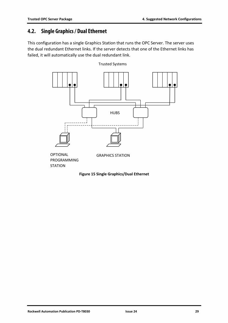
4.2. Single Graphics / Dual Ethernet
This configuration has a single Graphics Station that runs the OPC Server. The server uses the dual redundant Ethernet links. If the server detects that one of the Ethernet links has failed, it will automatically use the dual redundant link.
Figure 15 Single Graphics/Dual Ethernet
HUBS
GRAPHICS STATION OPTIONAL PROGRAMMING STATION
Trusted Systems
4. Suggested Network Configurations Trusted OPC Server Package
30 Issue 24 Rockwell Automation Publication PD-T8030
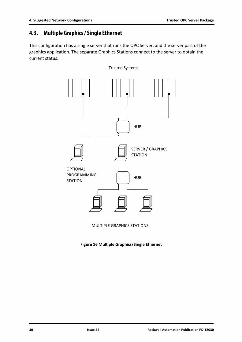
4.3. Multiple Graphics / Single Ethernet
This configuration has a single server that runs the OPC Server, and the server part of the graphics application. The separate Graphics Stations connect to the server to obtain the current status.
Figure 16 Multiple Graphics/Single Ethernet
HUB
SERVER / GRAPHICS STATION
OPTIONAL PROGRAMMING STATION
HUB
MULTIPLE GRAPHICS STATIONS
Trusted Systems
Trusted OPC Server Package 4. Suggested Network Configurations
Rockwell Automation Publication PD-T8030 Issue 24 31
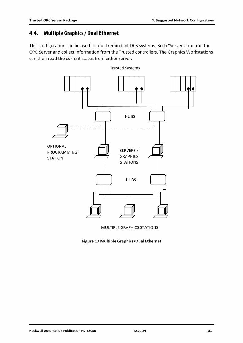
4.4. Multiple Graphics / Dual Ethernet
This configuration can be used for dual redundant DCS systems. Both “Servers” can run the OPC Server and collect information from the Trusted controllers. The Graphics Workstations can then read the current status from either server.
Figure 17 Multiple Graphics/Dual Ethernet
HUBS
SERVERS / GRAPHICS STATIONS
OPTIONAL PROGRAMMING STATION
HUBS
MULTIPLE GRAPHICS STATIONS
Trusted Systems
4. Suggested Network Configurations Trusted OPC Server Package
32 Issue 24 Rockwell Automation Publication PD-T8030
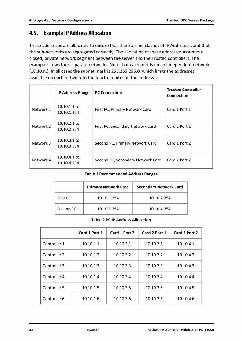
4.5. Example IP Address Allocation
These addresses are allocated to ensure that there are no clashes of IP Addresses, and that the sub-networks are segregated correctly. The allocation of these addresses assumes a closed, private network segment between the server and the Trusted controllers. The example shows four separate networks. Note that each port is on an independent network (10.10.n.). In all cases the subnet mask is 255.255.255.0, which limits the addresses available on each network to the fourth number in the address.
IP Address Range PC Connection Trusted Controller Connection
Network 1 10.10.1.1 to 10.10.1.254
First PC, Primary Network Card Card 1 Port 1
Network 2 10.10.2.1 to 10.10.2.254
First PC, Secondary Network Card Card 2 Port 1
Network 3 10.10.3.1 to 10.10.3.254
Second PC, Primary Network Card Card 1 Port 2
Network 4 10.10.4.1 to 10.10.4.254
Second PC, Secondary Network Card Card 2 Port 2
Table 1 Recommended Address Ranges
Primary Network Card Secondary Network Card
First PC 10.10.1.254 10.10.2.254
Second PC 10.10.3.254 10.10.4.254
Table 2 PC IP Address Allocation
Card 1 Port 1 Card 1 Port 2 Card 2 Port 1 Card 2 Port 2
Controller 1 10.10.1.1 10.10.3.1 10.10.2.1 10.10.4.1
Controller 2 10.10.1.2 10.10.3.2 10.10.2.2 10.10.4.2
Controller 3 10.10.1.3 10.10.3.3 10.10.2.3 10.10.4.3
Controller 4 10.10.1.4 10.10.3.4 10.10.2.4 10.10.4.4
Controller 5 10.10.1.5 10.10.3.5 10.10.2.5 10.10.4.5
Controller 6 10.10.1.6 10.10.3.6 10.10.2.6 10.10.4.6

Trusted OPC Server Package 4. Suggested Network Configurations
Rockwell Automation Publication PD-T8030 Issue 24 33
Card 1 Port 1 Card 1 Port 2 Card 2 Port 1 Card 2 Port 2
Controller 7 10.10.1.7 10.10.3.7 10.10.2.7 10.10.4.7
Controller 8 10.10.1.8 10.10.3.8 10.10.2.8 10.10.4.8
Table 3 Trusted Controller IP Address Allocation
Trusted OPC Server Package 5. DCOM Configuration
Rockwell Automation Publication PD-T8030 Issue 24 34
5. DCOM Configuration
The OPC Server can be used in a configuration with the server and client on separate PCs. To do this the DCOM protocol is used to communicate between the PCs.
To configure DCOM to allow the PCs to communicate, follow the instructions for the appropriate operating system. The configuration must be done with a user that is in the Administrators group.
Note: The Gateway module (8170) already has the default settings configured correctly. Therefore only the OPC Server specific settings need to be applied.
When configured, the same username and password must be used on the OPC Server PC and the OPC client PC. The users must be members of the Administrators group on their respective PCs.
Note that the example figures below will appear differently on Windows 2000, Windows XP Service Pack 1 and Windows XP ServicePack 2.
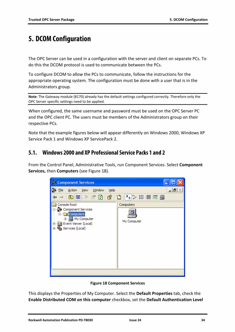
5.1. Windows 2000 and XP Professional Service Packs 1 and 2
From the Control Panel, Administrative Tools, run Component Services. Select Component Services, then Computers (see Figure 18).
Figure 18 Component Services
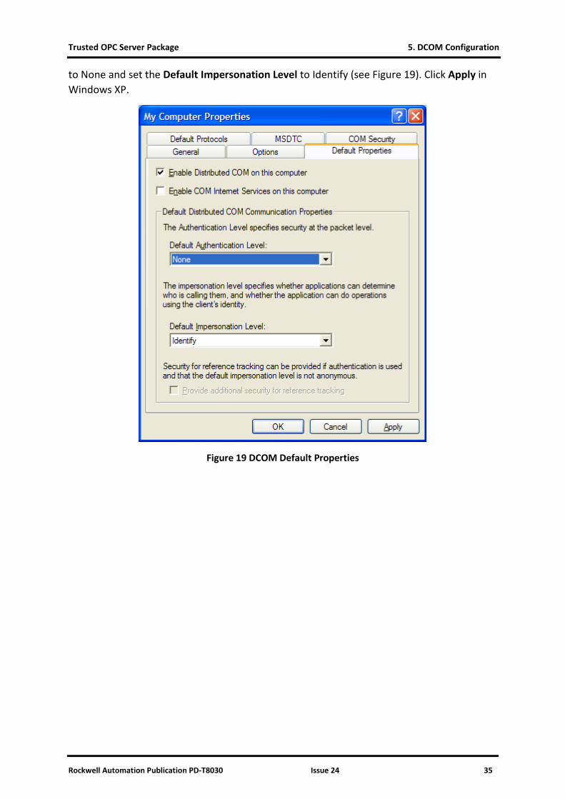
This displays the Properties of My Computer. Select the Default Properties tab, check the Enable Distributed COM on this computer checkbox, set the Default Authentication Level
Trusted OPC Server Package 5. DCOM Configuration
Rockwell Automation Publication PD-T8030 Issue 24 35
to None and set the Default Impersonation Level to Identify (see Figure 19). Click Apply in Windows XP.
Figure 19 DCOM Default Properties
5. DCOM Configuration Trusted OPC Server Package
36 Issue 24 Rockwell Automation Publication PD-T8030
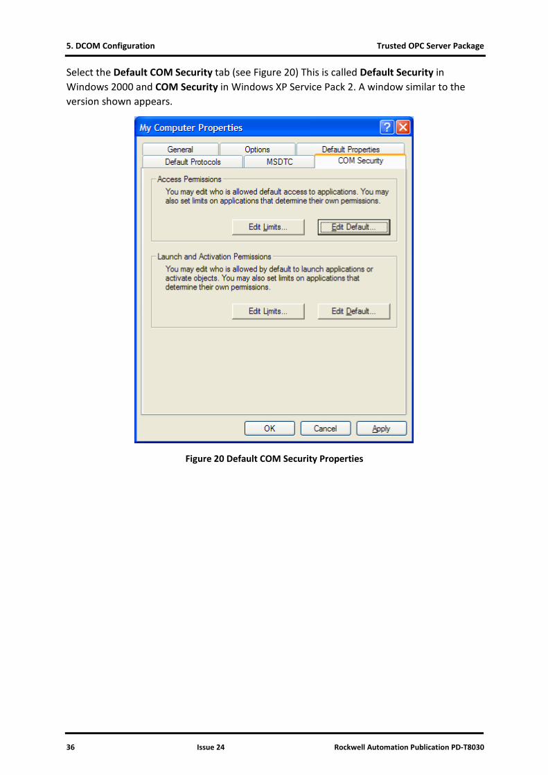
Select the Default COM Security tab (see Figure 20) This is called Default Security in Windows 2000 and COM Security in Windows XP Service Pack 2. A window similar to the version shown appears.
Figure 20 Default COM Security Properties
Trusted OPC Server Package 5. DCOM Configuration
Rockwell Automation Publication PD-T8030 Issue 24 37
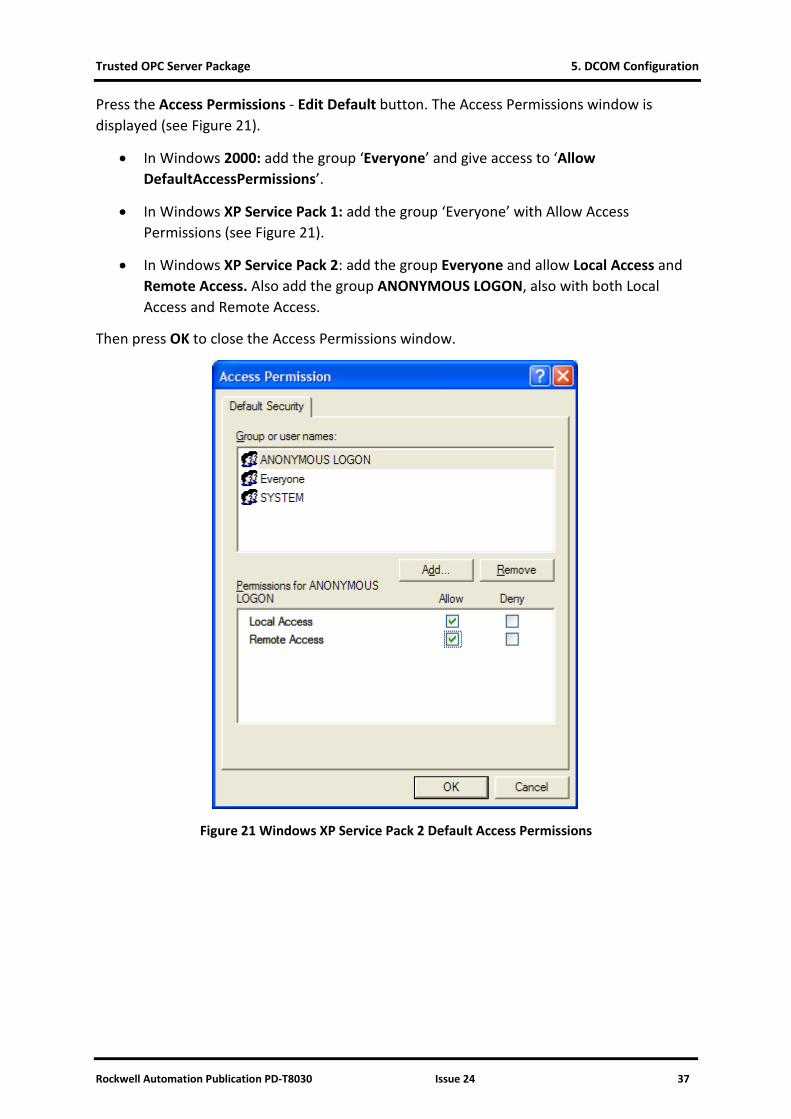
Press the Access Permissions - Edit Default button. The Access Permissions window is displayed (see Figure 21).
• In Windows 2000: add the group ‘Everyone’ and give access to ‘Allow DefaultAccessPermissions’.
• In Windows XP Service Pack 1: add the group ‘Everyone’ with Allow Access Permissions (see Figure 21).
• In Windows XP Service Pack 2: add the group Everyone and allow Local Access and Remote Access. Also add the group ANONYMOUS LOGON, also with both Local Access and Remote Access.
Then press OK to close the Access Permissions window.
Figure 21 Windows XP Service Pack 2 Default Access Permissions
5. DCOM Configuration Trusted OPC Server Package
38 Issue 24 Rockwell Automation Publication PD-T8030
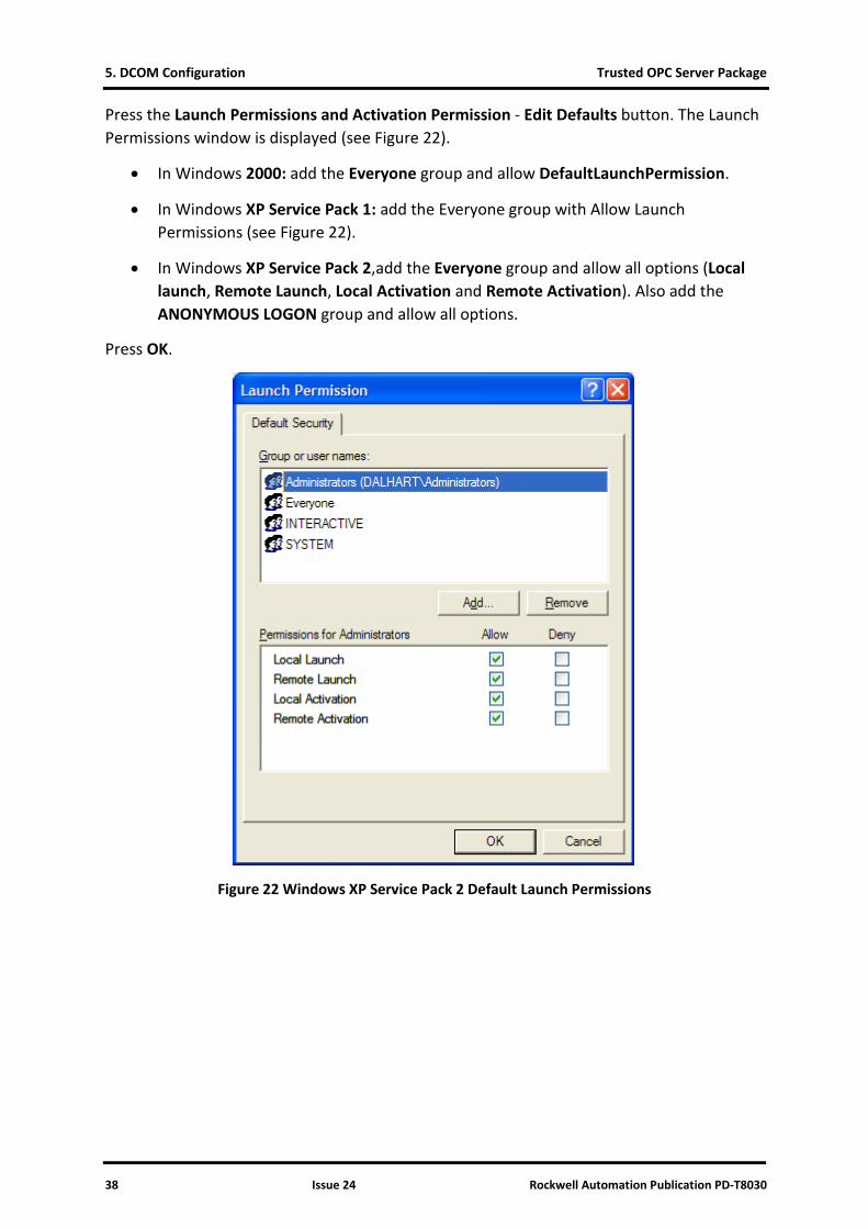
Press the Launch Permissions and Activation Permission - Edit Defaults button. The Launch Permissions window is displayed (see Figure 22).
• In Windows 2000: add the Everyone group and allow DefaultLaunchPermission.
• In Windows XP Service Pack 1: add the Everyone group with Allow Launch Permissions (see Figure 22).
• In Windows XP Service Pack 2,add the Everyone group and allow all options (Local launch, Remote Launch, Local Activation and Remote Activation). Also add the ANONYMOUS LOGON group and allow all options.
Press OK.
Figure 22 Windows XP Service Pack 2 Default Launch Permissions
Trusted OPC Server Package 5. DCOM Configuration
Rockwell Automation Publication PD-T8030 Issue 24 39
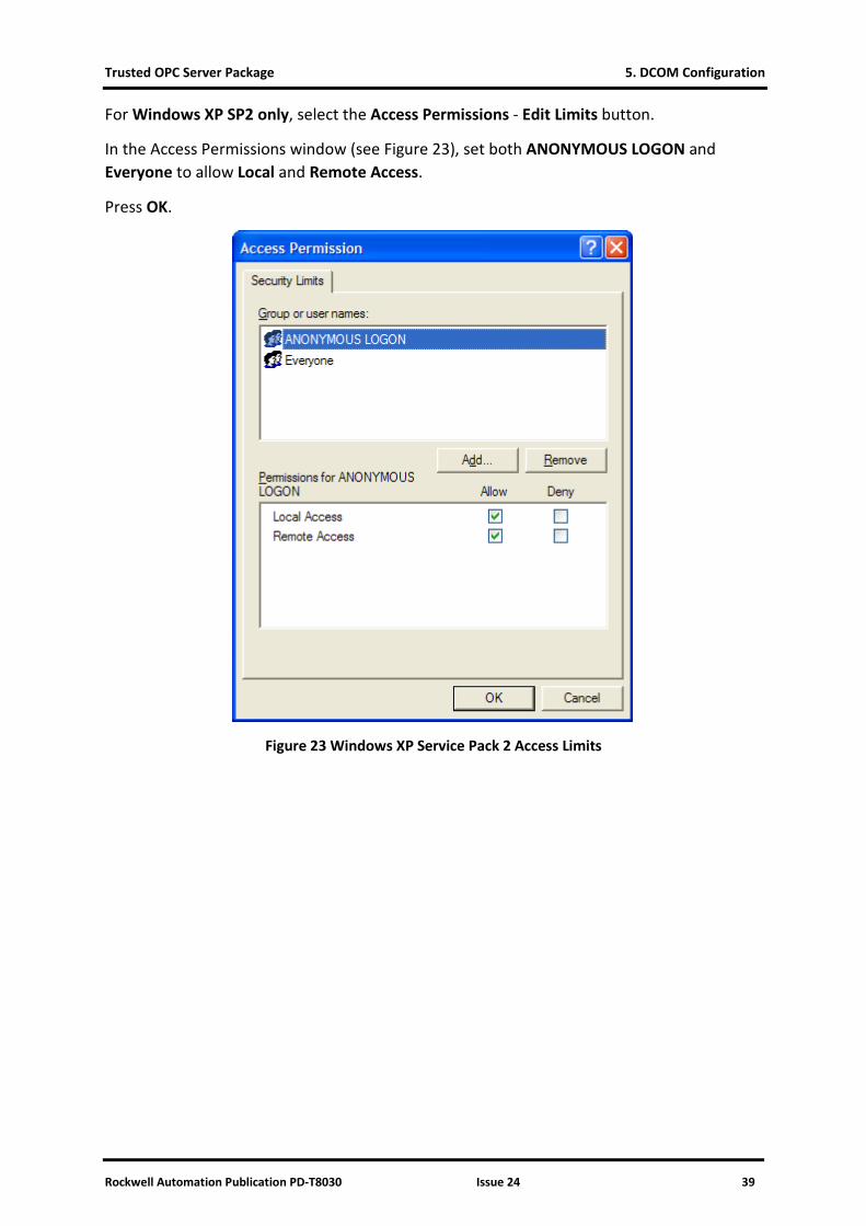
For Windows XP SP2 only, select the Access Permissions - Edit Limits button.
In the Access Permissions window (see Figure 23), set both ANONYMOUS LOGON and Everyone to allow Local and Remote Access.
Press OK.
Figure 23 Windows XP Service Pack 2 Access Limits
5. DCOM Configuration Trusted OPC Server Package
40 Issue 24 Rockwell Automation Publication PD-T8030
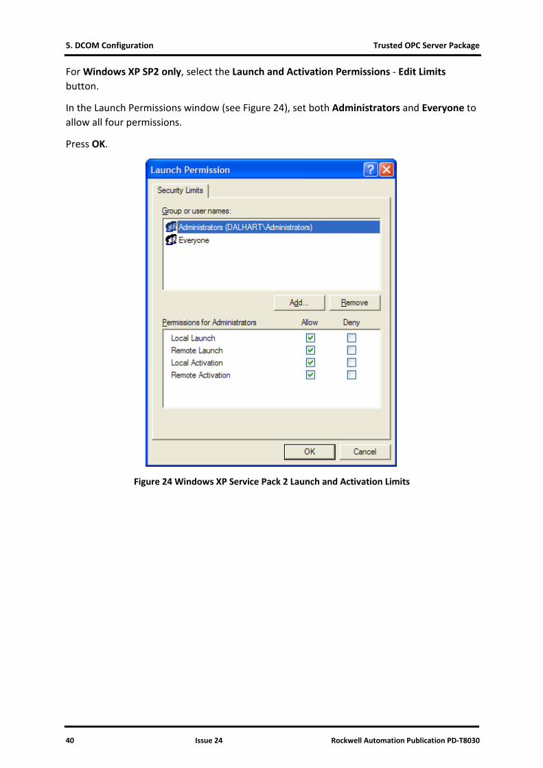
For Windows XP SP2 only, select the Launch and Activation Permissions - Edit Limits button.
In the Launch Permissions window (see Figure 24), set both Administrators and Everyone to allow all four permissions.
Press OK.
Figure 24 Windows XP Service Pack 2 Launch and Activation Limits
Trusted OPC Server Package 5. DCOM Configuration
Rockwell Automation Publication PD-T8030 Issue 24 41
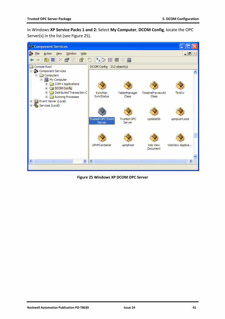
In Windows XP Service Packs 1 and 2: Select My Computer, DCOM Config, locate the OPC Server(s) in the list (see Figure 25).
Figure 25 Windows XP DCOM OPC Server
5. DCOM Configuration Trusted OPC Server Package
42 Issue 24 Rockwell Automation Publication PD-T8030
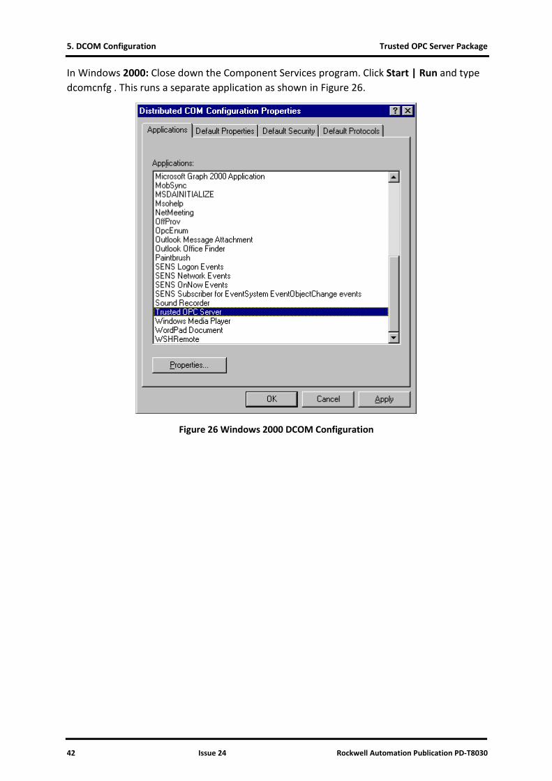
In Windows 2000: Close down the Component Services program. Click Start | Run and type dcomcnfg . This runs a separate application as shown in Figure 26.
Figure 26 Windows 2000 DCOM Configuration
Trusted OPC Server Package 5. DCOM Configuration
Rockwell Automation Publication PD-T8030 Issue 24 43
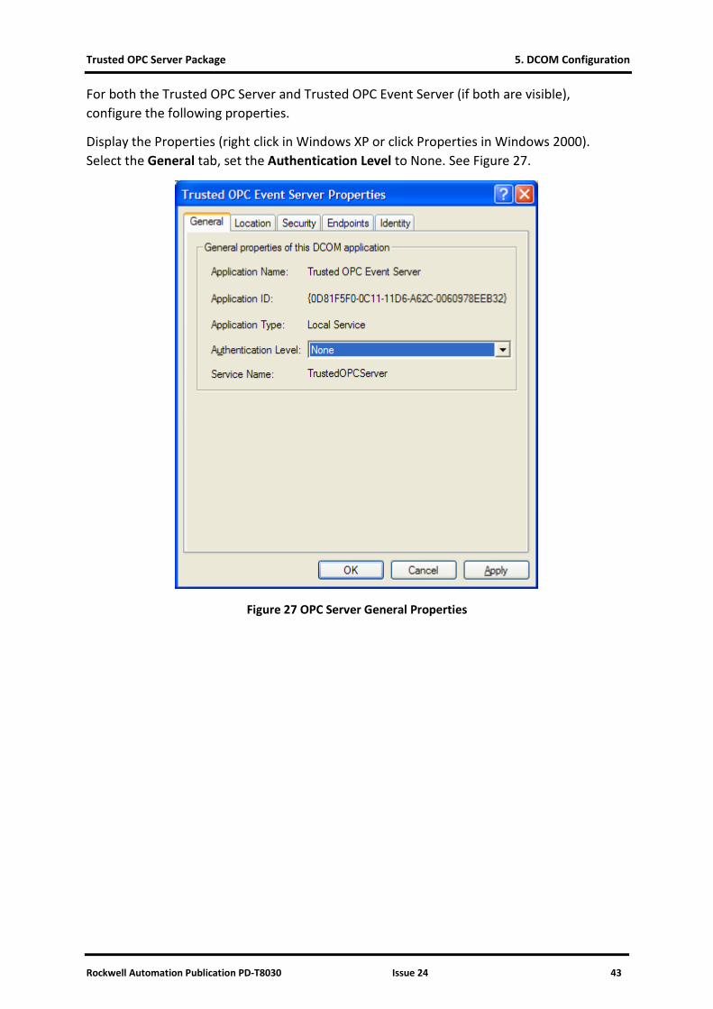
For both the Trusted OPC Server and Trusted OPC Event Server (if both are visible), configure the following properties.
Display the Properties (right click in Windows XP or click Properties in Windows 2000). Select the General tab, set the Authentication Level to None. See Figure 27.
Figure 27 OPC Server General Properties
5. DCOM Configuration Trusted OPC Server Package
44 Issue 24 Rockwell Automation Publication PD-T8030
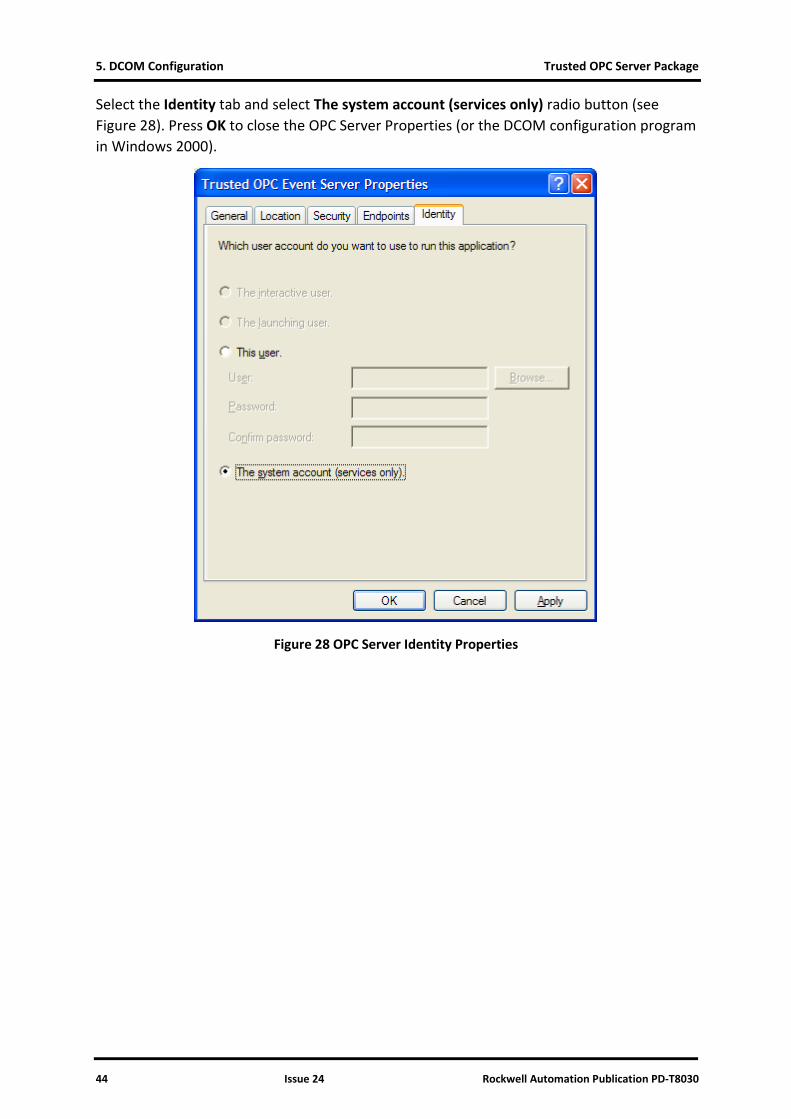
Select the Identity tab and select The system account (services only) radio button (see Figure 28). Press OK to close the OPC Server Properties (or the DCOM configuration program in Windows 2000).
Figure 28 OPC Server Identity Properties
Trusted OPC Server Package 5. DCOM Configuration
Rockwell Automation Publication PD-T8030 Issue 24 45
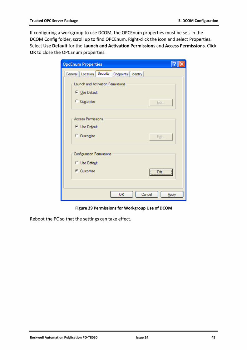
If configuring a workgroup to use DCOM, the OPCEnum properties must be set. In the DCOM Config folder, scroll up to find OPCEnum. Right-click the icon and select Properties. Select Use Default for the Launch and Activation Permissions and Access Permissions. Click OK to close the OPCEnum properties.
Figure 29 Permissions for Workgroup Use of DCOM
Reboot the PC so that the settings can take effect.
Trusted OPC Server Package 6. OPC Registry Details
Rockwell Automation Publication PD-T8030 Issue 24 46
6. OPC Registry Details
This information is required for some clients to allow them to recognise the servers.
6.1. Trusted OPC Server Registry
ClassID (and AppID):
0A7C43E0-433E-11D0-9F78-006097854444
ProgID:
ICSTriplex.Trusted.1
Implemented Categories:
63D5F430-CFE4-11D1-B2C8-0060083BA1FB
63D5F431-CFE4-11D1-B2C8-0060083BA1FB
63D5F432-CFE4-11D1-B2C8-0060083BA1FB
6.2. Trusted OPC Event Server Registry
ClassID (and AppID):
58E13251-AC87-11D1-84D5-00608CB8A7E9
ProgID:
ICSTriplex.Event.1
Implemented Categories:
58E13251-AC87-11D1-84D5-00608CB8A7E9

Trusted OPC Server Package 6. OPC Registry Details
Rockwell Automation Publication PD-T8030 Issue 24 47
Page intentionally left blank
Trusted OPC Server Package 7. Specifications
Rockwell Automation Publication PD-T8030 Issue 24 48
7. Specifications
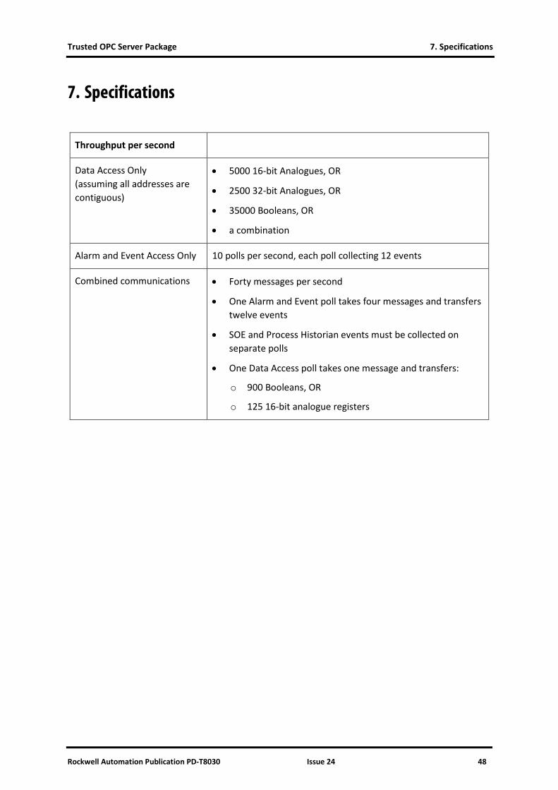
Throughput per second
Data Access Only (assuming all addresses are contiguous)
• 5000 16-bit Analogues, OR
• 2500 32-bit Analogues, OR
• 35000 Booleans, OR
• a combination
Alarm and Event Access Only 10 polls per second, each poll collecting 12 events
Combined communications • Forty messages per second
• One Alarm and Event poll takes four messages and transfers twelve events
• SOE and Process Historian events must be collected on separate polls
• One Data Access poll takes one message and transfers:
o 900 Booleans, OR
o 125 16-bit analogue registers