truss uplift design - drj best practices · truss uplift connection design for wind ... • this...
TRANSCRIPT
Truss Uplift Connection Design for Wind
Design Guide
Revised 3/22/2017
SBCA has been the voice of the structural building
components industry since 1983, providing educational
programs and technical information, disseminating industry
news, and facilitating networking opportunities for
manufacturers of roof trusses, wall panels and floor trusses.
SBCA endeavors to expand component manufacturers’
market share and enhance the professionalism of the
component manufacturing industry.
Copyright © 2017 Structural Building Components Association.

Introduction
• ASCE/SEI 7-10, Minimum Design Loads of Buildings and Other Structures, lists two methods for calculating wind pressures:– MWFRS (Main Wind Force
Resisting System)– C&C (Components and
Cladding)
MWFRS
C&C

Introduction
• Building designers, code officials and truss designers may question which method to use when designing uplift connections for trusses.
• This presentation will provide a step by step approach to assist the building designer in deciding upon the appropriate analysis method for uplift due to wind loading.
Introduction
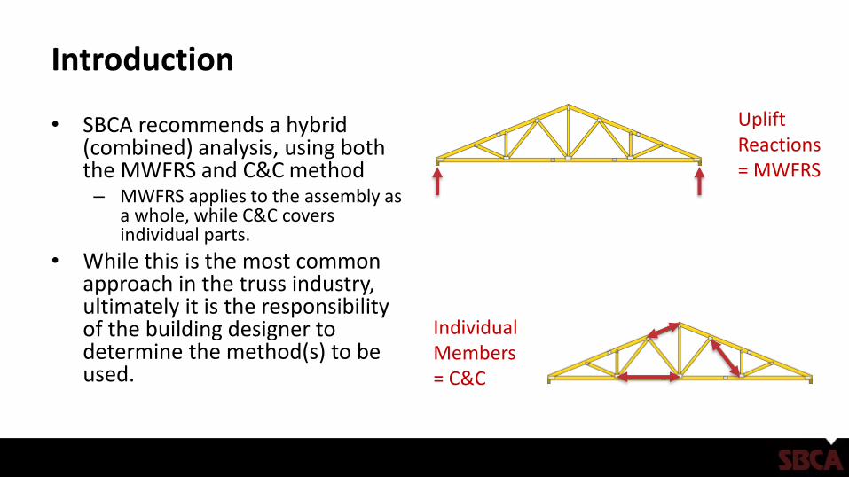
• SBCA recommends a hybrid (combined) analysis, using both the MWFRS and C&C method– MWFRS applies to the assembly as
a whole, while C&C covers individual parts.
• While this is the most common approach in the truss industry, ultimately it is the responsibility of the building designer to determine the method(s) to be used.
Uplift Reactions = MWFRS
Individual Members = C&C

Step 1: Understand Responsibilities
• The truss designer needs as much loading information as possible from the building designer in order to design the trusses.
• The building designer is responsible for providing the structural design documents and all of the load and dimension information necessary to design the trusses.
• If a project does not require a licensed professional building designer, the owner or the owner’s agent is responsible for providing this information.

Step 2: Check Building Code Applicability
• The IRC design scope for wind is limited in Section R301.2.1.1 as follows:– IRC 2015 – where design is not required in
accordance with Figure R301.2(4)B. • This is generally all areas with an ultimate wind
speed of 130 mph(Vult) or less except in the New England states where wind speeds up to 140 mph are allowed.
– IRC 2012 – less than 110 mph (Basic wind speed, Vasd) or where design is not required in accordance with Figure R301.2(4)B
– IRC 2006 and 2009 – less than 100 mph in hurricane prone regions and less than 110 mph elsewhere.

Step 3: Check Site-Specific Information
• The truss designer must rely on the building designer to provide accurate site-specific wind information per Table R301.2(1):– Basic (Vasd) or Ultimate (Vult) Wind speed (3 second gust) and whether or not the structure is in
a hurricane-prone region– Exposure Category– Plus: mean roof height (if not given, 15 feet would be typical for a one-story, 25 feet would be
typical for a two-story)
• The default Exposure Category in the IRC is “B”, but adjustments for Exposure Categories C & D as well as mean roof heights up to 60 feet are provided.

Step 4: Check Structure-Specific Information
• Generally, the following design criteria for structures within the scope of the IRC can be used. – Importance Factor (I) = 1.0
– Enclosure Category = Enclosed
– Topographic Factor (KZT) = 1.0
– Directionality Factor (KD) = 0.85
• Always verify any assumptions made with the building design where they are not shown on the construction documents.
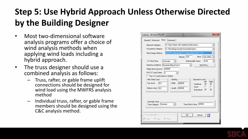
Step 5: Use Hybrid Approach Unless Otherwise Directed by the Building Designer
• Most two-dimensional software analysis programs offer a choice of wind analysis methods when applying wind loads including a hybrid approach.
• The truss designer should use a combined analysis as follows: – Truss, rafter, or gable frame uplift
connections should be designed for wind load using the MWFRS analysis method
– Individual truss, rafter, or gable frame members should be designed using the C&C analysis method.