truslift 750 installation and operation...
TRANSCRIPT

Trus<T>Lift 750
Installation and Operation ManualCopyright 2013
TRUS<T>LIFT 750 MANUAL
RAM Manufacturing Ltd. 1-800-563-4382 1 | P a g e
Contents
Section 1: Intro ................................................................................................................................2
Section 2: Safety ..............................................................................................................................2
Section 3: Operating Instructions...................................................................................................3
Section 4: Installation – Site Preparation ......................................................................................5
Section 5: Installation –Basic Lift Assembly...................................................................................6
Section 6: Installing Options.........................................................................................................11
Section 7: Mounting the Tower to a Wall....................................................................................26
Section 8: Tall Tower Lifting Instructions.....................................................................................30
Section 9: Maintenance ................................................................................................................33
Section 10: Basic Trouble Shooting................................................................................................41
Appendix A: Trus <T> LIFT Assembly Drawings (with part numbers).............................................42
Upper Landing Gate Drawing (with part numbers)..........................................................................44
Appendix B: Basic Electrical Drawing ................................................................................................45
Appendix C: Maintenance Log...........................................................................................................47

TRUS<T>LIFT 750 MANUAL
RAM Manufacturing Ltd. 1-800-563-4382 2 | P a g e
Section 1: Intro
Thank you for selecting the Trus <T> Lift. When operated properly the Trus<T>Lift is designed to provide years of trouble free service. This manual is provided to show you how to operate the lift safely and efficiently. Please read this manual thoroughly before installing and operating your lift for the first time. We recommend your lift be installed and serviced by a qualified service technician. If you are having problems installing the lift call our tech support line at 1-800-563-4382.
Section 2: Safety
Read all instructions thoroughly before installation or use of this lift. Failure to do so couldresult in serious injury or death.
Refer to local building codes, elevator codes and elevator authorities to ensure installation is safe and meets your local regulations.
The tower component of all lifts over 52” travel must be secured to the building for additional support. For commercial installations we recommend the tower be secured to the building for all lifting heights.
We recommend your lift be installed and serviced by a qualified service technician. Do not override any of the safety devices provided with the lift Make sure that there is nothing obstructing the carriage travel before operating the lift. Make sure there is a minimum of 2in (50mm) and a maximum of 3in (75mm) clearance
between any part or edge of the carriage that could possibly be used as a supporting handhold and any part of the fixed installation to prevent the trapping of a hand during the travel of the carriage.
The lift is intended for use by one passenger and one wheelchair only, to a maximum of 750 lb. (DO NOT OVERLOAD THE LIFT).
Make sure that the passenger and the wheelchair are completely on the carriage before raising or lowering the lift.
Please use the handrails while the carriage is in motion. This list may not be exhaustive, due care around mechanical equipment should be
observed. If uncertain, please contact the manufacture or a qualified installer.
For product updates and bulletins, please refer to our website www.trustram.com
TRUS<T>LIFT 750 MANUAL
RAM Manufacturing Ltd. 1-800-563-4382 3 | P a g e
Section 3: Operating Instructions
Plug the unit into your power supply. On the end of the power cord you will find the gold key to open the control box, use this to open the main control box by pushing in hard on the box with one hand to compress the weather seal while turning the key with the other hand. All other keys for the unit will be hanging on the back of the control box door.
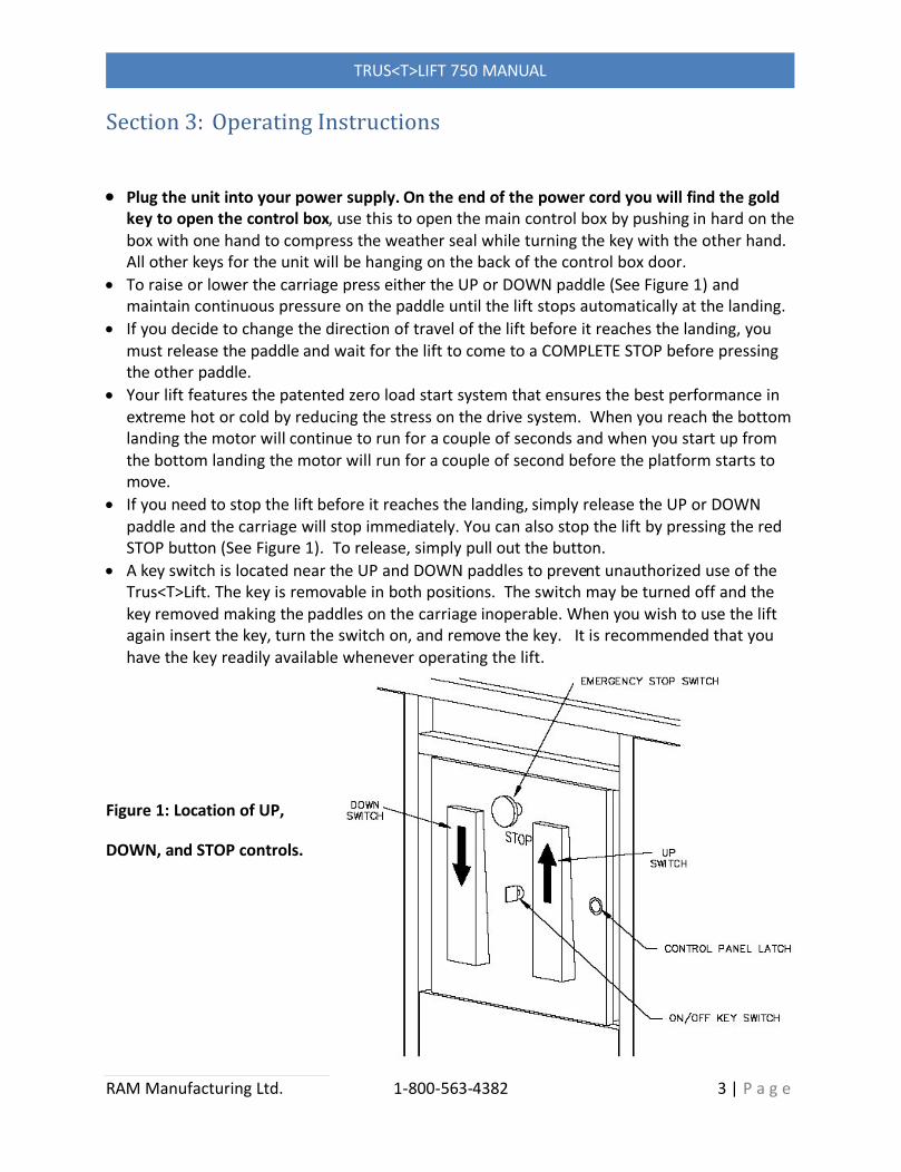
To raise or lower the carriage press either the UP or DOWN paddle (See Figure 1) and maintain continuous pressure on the paddle until the lift stops automatically at the landing.
If you decide to change the direction of travel of the lift before it reaches the landing, you must release the paddle and wait for the lift to come to a COMPLETE STOP before pressing the other paddle.
Your lift features the patented zero load start system that ensures the best performance in extreme hot or cold by reducing the stress on the drive system. When you reach the bottom landing the motor will continue to run for a couple of seconds and when you start up from the bottom landing the motor will run for a couple of second before the platform starts to move.
If you need to stop the lift before it reaches the landing, simply release the UP or DOWN paddle and the carriage will stop immediately. You can also stop the lift by pressing the red STOP button (See Figure 1). To release, simply pull out the button.
A key switch is located near the UP and DOWN paddles to prevent unauthorized use of the Trus<T>Lift. The key is removable in both positions. The switch may be turned off and the key removed making the paddles on the carriage inoperable. When you wish to use the lift again insert the key, turn the switch on, and remove the key. It is recommended that you have the key readily available whenever operating the lift.
Figure 1: Location of UP,
DOWN, and STOP controls.

TRUS<T>LIFT 750 MANUAL
RAM Manufacturing Ltd. 1-800-563-4382 4 | P a g e
MANUAL CRANK OPERATION
If a power outage occurs while the lift is in use and a passenger is stranded between landings, the carriage can be manually raised or lowered using the Hand Crank Tool provided. First verify manual cranking is required, ensure the stop button is pulled out, the control key is turned on and the lift is plugged in. If manual cranking is still required follow these steps:
When manual cranking the lift there is a pinching risk between the belt and the pulleys. Keep your hands, hair, clothing and jewellery clear of the drive belt.
Unplug the power cord Remove the top cover of the lift Use the 15/16” socket and ratchet provided to crank the bolt on the topcenter of the tower (See Figure 2). Turn the Hand Crank Tool clockwiseto raise the lift and counter-clockwise to lower the
lift. Figure 2: Manual Crank Access

TRUS<T>LIFT 750 MANUAL
RAM Manufacturing Ltd. 1-800-563-4382 5 | P a g e
Section 4: Installation – Site Preparation
4.1 Mounting location
The Trus<T>Lift requires a solid, smooth, and level mounting surface. When mounting on a concrete pad ensure there is a minimum of 6in from any anchor point tothe pad edge to prevent cracking the concrete. Plan for a minimum of 60in x 60in additional space (not including the toeplate) on the lower entrance side to allow enough space for the wheelchair to manoeuvre onto the lift.
The mounting surface must be solid enough to support the lift and its maximum rated load.
Note: The Trus<T>Lift ships with four 3/8” x 2 ¾” concrete wedge anchors.
For wedge anchor installation information visit
http://trustram.com/concrete-anchor/
4.2 Travel WallThe travel wall is the wall below the upper entrance/exit point of the lift (Figure 4). This
wall should be vertical, smooth, and free of gaps or protrusions for the entire travel distance of the lift.
4.3 PowerA 110 VAC 15A electrical receptacle must be provided within 6 feet of the tower side of the lift. You can use an extension cord if required. Total length of line including the cord attached to the unit must not exceed 20 ft. Use only 14 gage extension cord. Residential lifts should use a dedicated circuit where possible. Commercial applications require a disconnect and a dedicated circuit.
Figure 3: Typical Installation

TRUS<T>LIFT 750 MANUAL
RAM Manufacturing Ltd. 1-800-563-4382 6 | P a g e
RAM manufactures numerous lift configurations. For lifts that have additional options (including commercial lifts) please see Section 6. The basic lift assembly instructions apply to all lifts regardless of configuration.
Section 5: Installation –Basic Lift Assembly
Position the tower on the mounting deck close to the final install position. (Note: choose a location where the carriage components can be assembled easily with the intention of moving the unit into final position after tower, base legs and carriage are fully assembled). (Figure 4)
Slide the base legs under the base angles on the tower.
Use safe lifting practices along with a dolly or other appropriate lifting equipment to move the tower into place.
Securely fasten base legs to the tower as shown in Figure 5 using provided ½ NF x 1 ¼” cap screws, ½ lock washers and ½ flat washers.
Adjust the front and back base leg load-support screws to lift the base frame slightly off the ground.
Note: Do not attach the base frame to the ground at this point, this setting will ensure the lift is supported on the outer points of the base frame for maximum stability. Later in the process the mid-load support screws will be adjusted to just touch the floor with no load on the carriage before the base legs are anchored to the ground.
Figure 4: Position Tower and Base Legs
Figure 5: Attach Base Legs to Tower

TRUS<T>LIFT 750 MANUAL
RAM Manufacturing Ltd. 1-800-563-4382 7 | P a g e
5.1 Attach the platform to the tower
Raise the guide frame using the manual crank or by temporarily plugging the unit in to a power outlet. Slide the platform into place on the base frame (Figure 6), be
careful not to scratch the base frame.
Hint!! Use packaging foam from the shipping crate to protect the base legs when installing platform.
Lower the guide frame to line up bolt holes on the carriage and install the bolts (Figure 7). Note: tighten the bolts until the end of the bolt is 1/8” of an inch out of the lock nut, do not over tighten the bolts.
Hint!! You can get a better view of the bolt extending through the nut by removing the plastic panels beside on the control box on
carriage wall.
5.2 Install handrail
Install the handrail using 5/16” NC x ¾ Capscrews with 2 washers and a nut on each cap screw as shown in (Figure 8).
Figure 6: Slide Platform In
Figure 7: Attach Platform
Figure 8: Install Handrail
Note: If the lift was purchased with any upper or lower interlocks, the lift will not run with the control paddles until the interlocks are properly wired into the control box at the top of the lift. See section 6 for options.
TRUS<T>LIFT 750 MANUAL
RAM Manufacturing Ltd. 1-800-563-4382 8 | P a g e
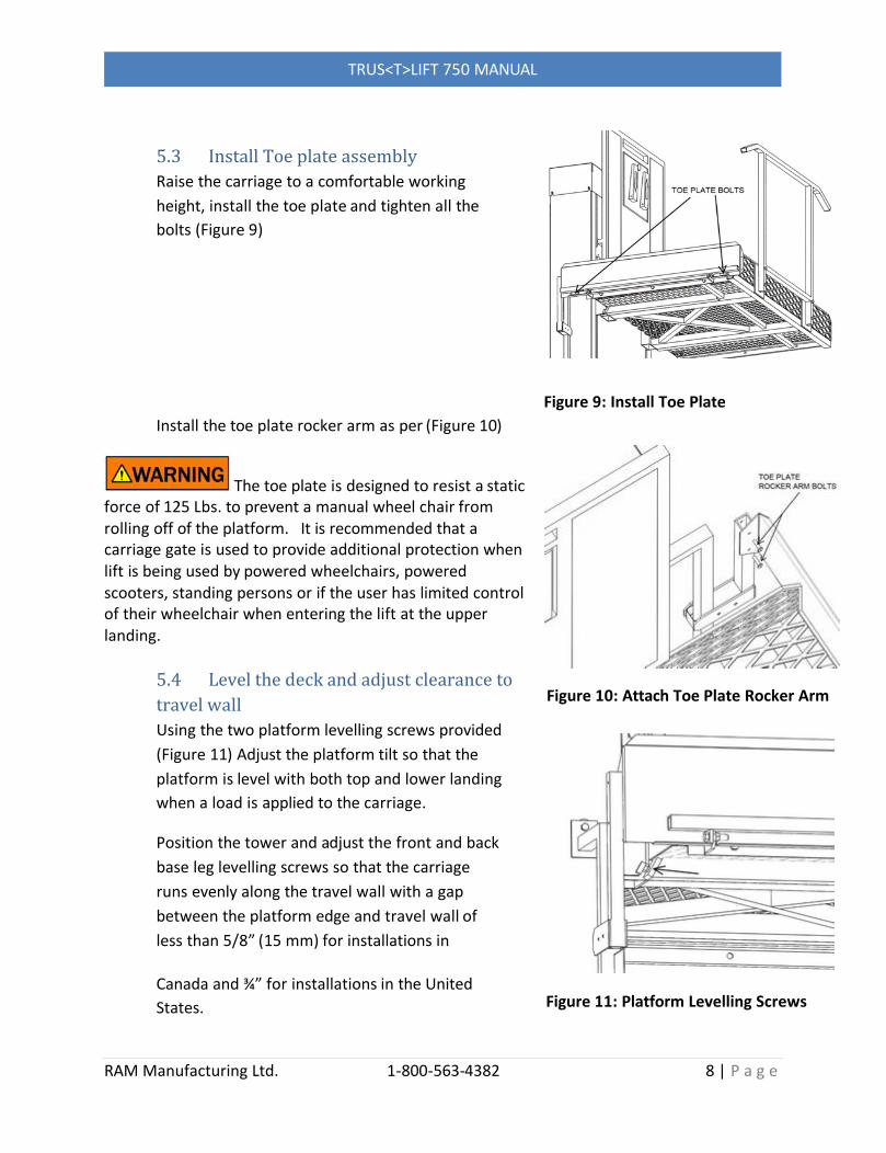
5.3 Install Toe plate assemblyRaise the carriage to a comfortable working height, install the toe plate and tighten all the bolts (Figure 9)
Install the toe plate rocker arm as per (Figure 10)
The toe plate is designed to resist a staticforce of 125 Lbs. to prevent a manual wheel chair from rolling off of the platform. It is recommended that a carriage gate is used to provide additional protection when lift is being used by powered wheelchairs, powered scooters, standing persons or if the user has limited control of their wheelchair when entering the lift at the upper landing.
5.4 Level the deck and adjust clearance to travel wallUsing the two platform levelling screws provided (Figure 11) Adjust the platform tilt so that the platform is level with both top and lower landing when a load is applied to the carriage.
Position the tower and adjust the front and back base leg levelling screws so that the carriage runs evenly along the travel wall with a gap between the platform edge and travel wall of less than 5/8” (15 mm) for installations in
Canada and ¾” for installations in the United States.
Figure 9: Install Toe Plate
Figure 10: Attach Toe Plate Rocker Arm
Figure 11: Platform Levelling Screws
TRUS<T>LIFT 750 MANUAL
RAM Manufacturing Ltd. 1-800-563-4382 9 | P a g e
5.5 Secure the lift to the building
Drill 3/8” holes through mounting holes in base legs. Use provided concrete anchors to attach base legs to concrete. (If attaching to another material then concrete use appropriate fasteners for the material you are working with).
If working with a commercial insulation or if lifting height is greater than 52”, attach the top of the tower to the building prior to attaching the base frame.
See Section 7 – Mounting the Tower to a Wall.
Lightly tighten middle levelling bolts until they touch the concrete pad, and thentighten them an additional ½ turn.
For wedge anchor installation information visit
http://trustram.com/concrete-anchor/
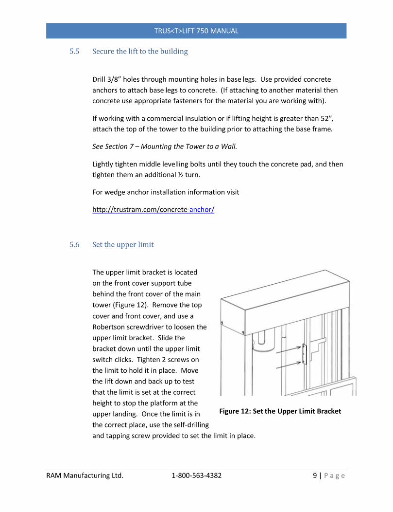
5.6 Set the upper limit
The upper limit bracket is located on the front cover support tube behind the front cover of the main tower (Figure 12). Remove the top cover and front cover, and use a Robertson screwdriver to loosen the upper limit bracket. Slide the bracket down until the upper limit switch clicks. Tighten 2 screws on the limit to hold it in place. Move the lift down and back up to test that the limit is set at the correct height to stop the platform at the upper landing. Once the limit is in the correct place, use the self-drilling and tapping screw provided to set the limit in place.
Figure 12: Set the Upper Limit Bracket

TRUS<T>LIFT 750 MANUAL
RAM Manufacturing Ltd. 1-800-563-4382 10 | P a g e

TRUS<T>LIFT 750 MANUAL
RAM Manufacturing Ltd. 1-800-563-4382 11 | P a g e
Section 6: Installing Options
6.1 Identify the Optional Components for your Lift
Not all lifts are shipped with the same components. Be sure to identify all the options you have purchased before assembly. Follow each step carefully to ensure proper functionality. Parts List - The options for the Trus<T>Lift are pre-assembled and tested in the factory before shipping. The lift is then disassembled into its separate components. All fasteners required to assemble the lift are re-installed in their respective positions after disassembly, except for the Lower Mechanical Stops (5/8” X 3” Carriage Bolts) included with the small parts bag.
6.2 Locating the Upper Junction Box
Call stations, upper gates and interlocks terminate in the upper junction box under the cover at the top of the lift.
Remove the cover from the top of the lift. (Note the lift will not run with the top cover removed.) Inside there is a junction box on the right side, remove the cover of this junction box. Inside the junction box there is a cable with individual wires labeled with numbered tags. Number tags are also on the end of the wires coming from the option to be hooked up. Figure 13
Mount the call station, upper gate and or interlocks into their respective positions.Run the wires from each option to the upper junction box through conduit. Using the wire nuts provided match the number on the wires to complete the terminations.
Figure 13: Upper Junction Box
The installation of a lift with options differs from a basic unit in that it requires all peripheral safety devices (i.e. upper interlock, lower interlock and safety Pan) to be wired up at least temporarily in order to run the motor.

TRUS<T>LIFT 750 MANUAL
RAM Manufacturing Ltd. 1-800-563-4382 12 | P a g e
Temporarily connect the upper-gate/interlock wire harness and the lower-door/interlock wire harness.
Temporarily connect the upper-gate/interlock wire harness and the lower-door/interlock wire harness (if provided) to the matching numbered wires in the outside junction box located on top right hand side of tower. The interlock gate latches must be inserted into the head of the interlock and the interlocks must be set to the locked position for the lift to operate. NOTE: Interlocks and Safety Pan must be connected or the lift will not operate.
See Section 6.4 Installing the Door or Gate Interlock and Section 6.7 installing the Safety Pan.
You will therefore have to use the manual cranking device for down or up movement. The manual cranking device provides an alternate method to move the carriage.
See Page 4 Manual Crank Operation
TRUS<T>LIFT 750 MANUAL
RAM Manufacturing Ltd. 1-800-563-4382 13 | P a g e
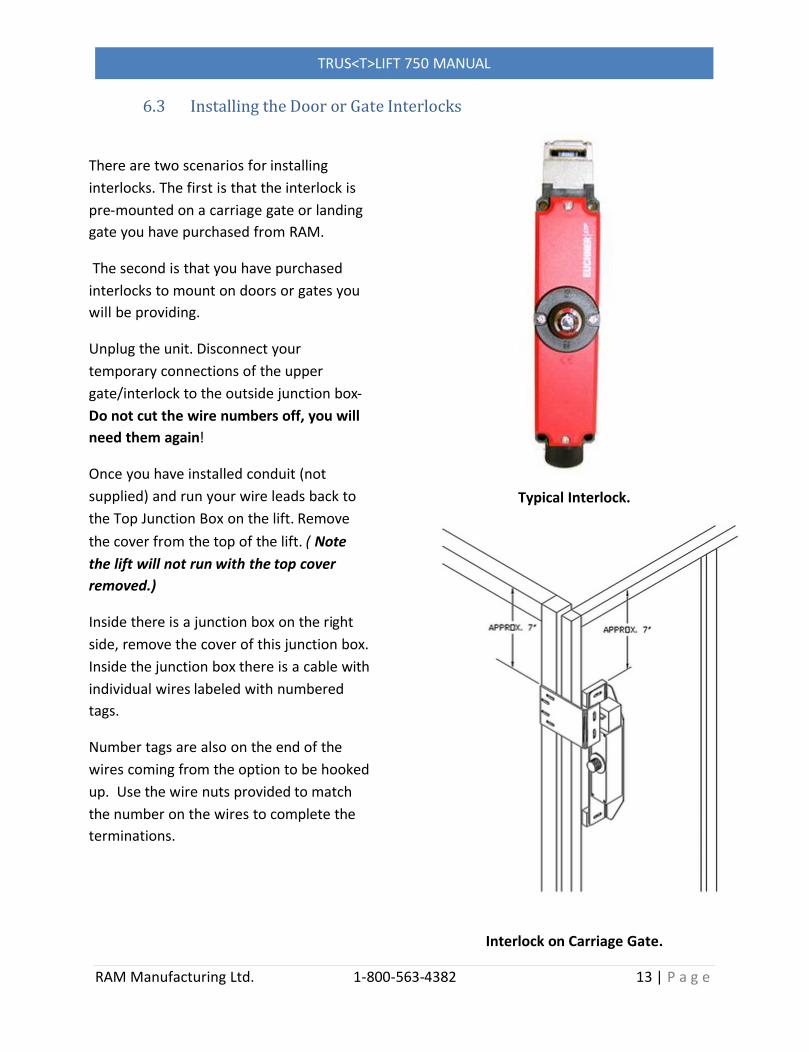
There are two scenarios for installing interlocks. The first is that the interlock is pre-mounted on a carriage gate or landing gate you have purchased from RAM.
The second is that you have purchased interlocks to mount on doors or gates you will be providing.
Unplug the unit. Disconnect your temporary connections of the upper gate/interlock to the outside junction box-Do not cut the wire numbers off, you will need them again!
Once you have installed conduit (not supplied) and run your wire leads back to the Top Junction Box on the lift. Remove the cover from the top of the lift. ( Note the lift will not run with the top cover removed.)
Inside there is a junction box on the right side, remove the cover of this junction box. Inside the junction box there is a cable with individual wires labeled with numbered tags.
Number tags are also on the end of the wires coming from the option to be hooked up. Use the wire nuts provided to match the number on the wires to complete the terminations.
6.3 Installing the Door or Gate Interlocks
Interlock on Carriage Gate.
Typical Interlock.
TRUS<T>LIFT 750 MANUAL
RAM Manufacturing Ltd. 1-800-563-4382 14 | P a g e
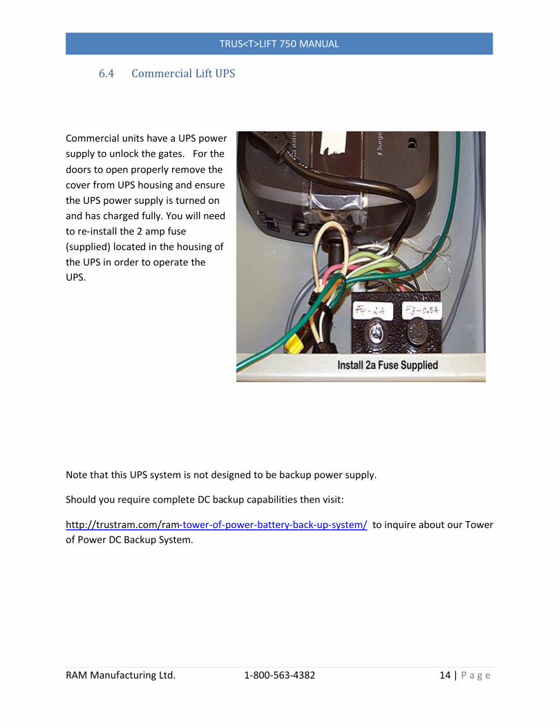
6.4 Commercial Lift UPS
Commercial units have a UPS power supply to unlock the gates. For the doors to open properly remove the cover from UPS housing and ensure the UPS power supply is turned on and has charged fully. You will need to re-install the 2 amp fuse (supplied) located in the housing of the UPS in order to operate the UPS.
Note that this UPS system is not designed to be backup power supply.
Should you require complete DC backup capabilities then visit:
http://trustram.com/ram-tower-of-power-battery-back-up-system/ to inquire about our Tower of Power DC Backup System.
TRUS<T>LIFT 750 MANUAL
RAM Manufacturing Ltd. 1-800-563-4382 15 | P a g e
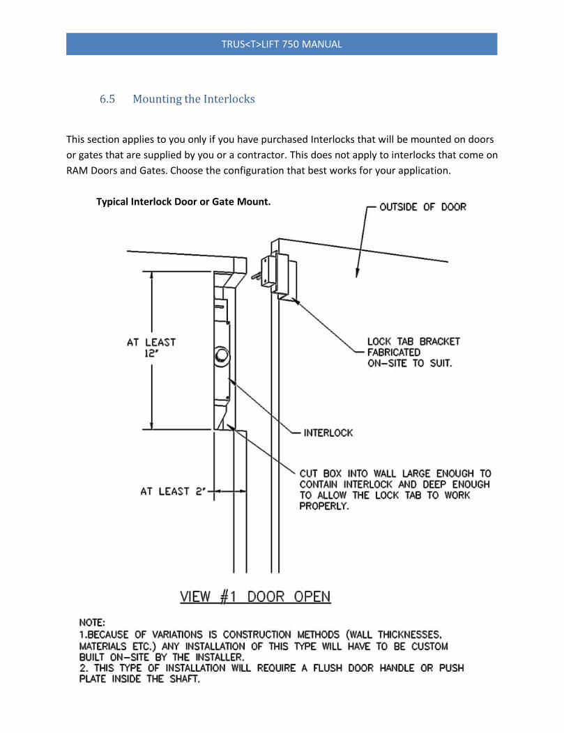
Typical Interlock Door or Gate Mount.
6.5 Mounting the Interlocks
This section applies to you only if you have purchased Interlocks that will be mounted on doors or gates that are supplied by you or a contractor. This does not apply to interlocks that come on RAM Doors and Gates. Choose the configuration that best works for your application.

TRUS<T>LIFT 750 MANUAL
RAM Manufacturing Ltd. 1-800-563-4382 16 | P a g e
Typical Interlock Door or Gate Mount.
TRUS<T>LIFT 750 MANUAL
RAM Manufacturing Ltd. 1-800-563-4382 17 | P a g e
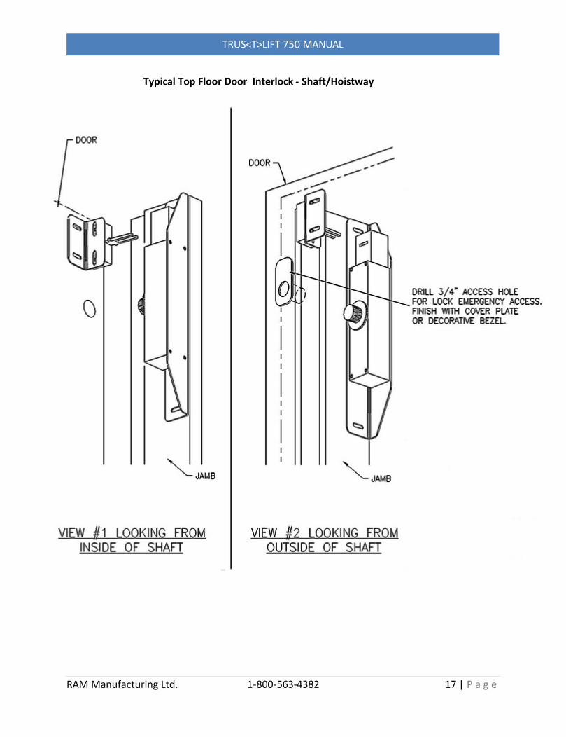
Typical Top Floor Door Interlock - Shaft/Hoistway Mount.

TRUS<T>LIFT 750 MANUAL
RAM Manufacturing Ltd. 1-800-563-4382 18 | P a g e
6.6 Installing Remote Call Stations
Typical Push Button Call Station.
Unplug the unit or shut off power.
Mount the Lower Remote Call Station in a suitable location.
Disconnect your temporary connections of the Upper Gate/Interlock to the Top Junction box- do not cut the wire numbers off, you will need them again!
Run electrical conduit from the Call Station to the Top Junction Box or the Upper Gate to the Top Junction Box.
Run the cable from the Call Station and the harness from the Upper Gate through the conduit to the Top Junction Box.
Reconnect the wires in the Top Junction Box, this time including the wires from the lower Call Station.
Restore power to the unit.
TRUS<T>LIFT 750 MANUAL
RAM Manufacturing Ltd. 1-800-563-4382 19 | P a g e
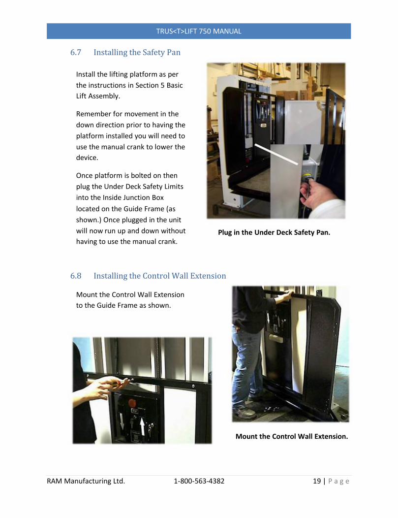
6.7 Installing the Safety Pan
6.8 Installing the Control Wall Extension
Plug in the Under Deck Safety Pan.
Mount the Control Wall Extension.
Install the lifting platform as per the instructions in Section 5 Basic Lift Assembly.
Remember for movement in the down direction prior to having the platform installed you will need to use the manual crank to lower the device.
Once platform is bolted on then plug the Under Deck Safety Limits into the Inside Junction Box located on the Guide Frame (as shown.) Once plugged in the unit will now run up and down without having to use the manual crank.
Mount the Control Wall Extension to the Guide Frame as shown.
TRUS<T>LIFT 750 MANUAL
RAM Manufacturing Ltd. 1-800-563-4382 20 | P a g e
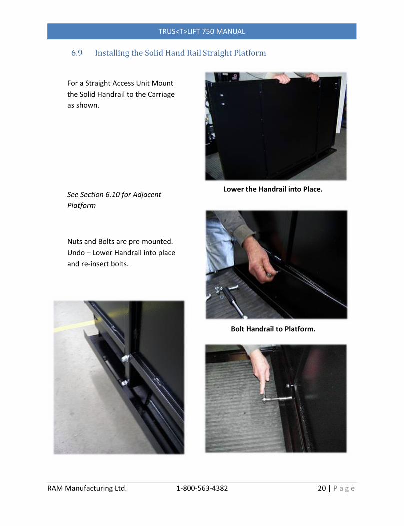
6.9 Installing the Solid Hand Rail Straight Platform
Lower the Handrail into Place.
Bolt Handrail to Platform.
For a Straight Access Unit Mount the Solid Handrail to the Carriage as shown.
See Section 6.10 for Adjacent Platform
Nuts and Bolts are pre-mounted. Undo – Lower Handrail into place and re-insert bolts.
TRUS<T>LIFT 750 MANUAL
RAM Manufacturing Ltd. 1-800-563-4382 21 | P a g e
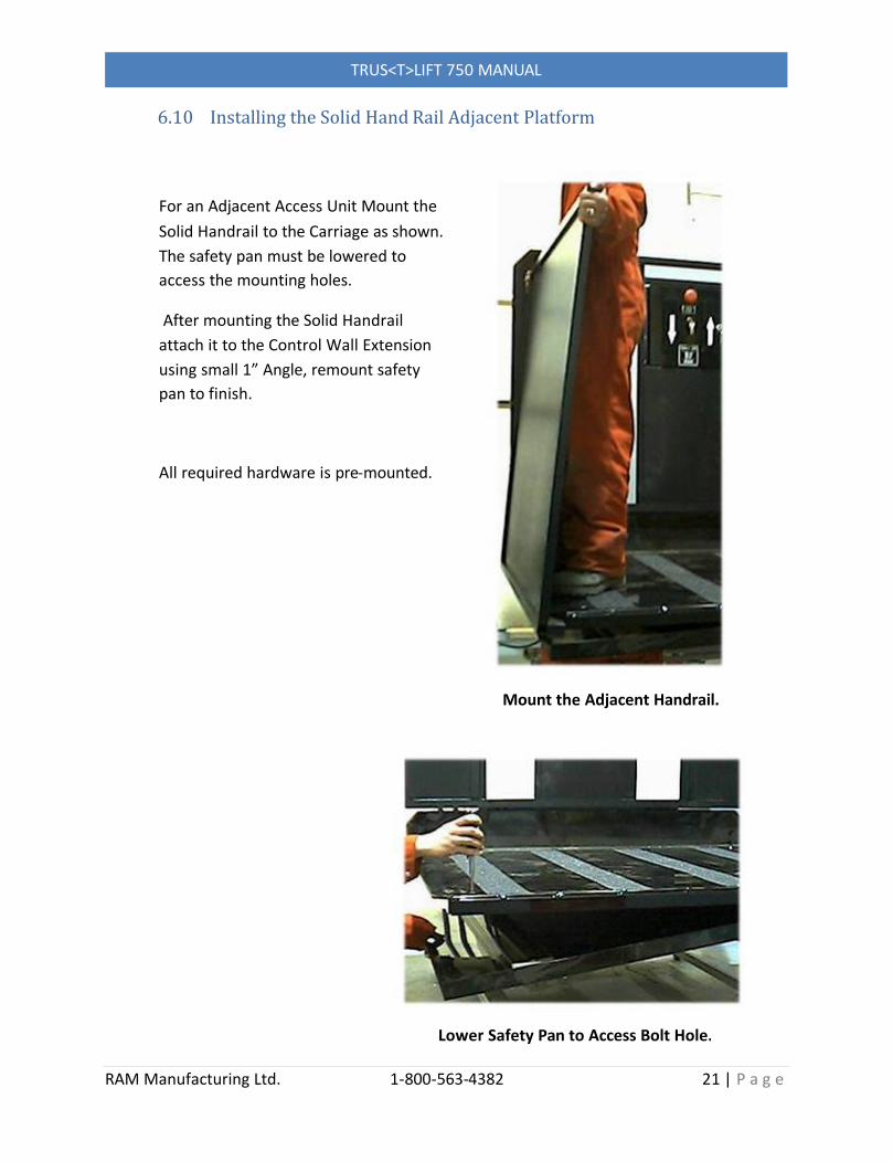
Mount the Adjacent Handrail.
Lower Safety Pan to Access Bolt Hole.
6.10 Installing the Solid Hand Rail Adjacent Platform
For an Adjacent Access Unit Mount the Solid Handrail to the Carriage as shown. The safety pan must be lowered to access the mounting holes.
After mounting the Solid Handrail attach it to the Control Wall Extension using small 1” Angle, remount safety pan to finish.
All required hardware is pre-mounted.

TRUS<T>LIFT 750 MANUAL
RAM Manufacturing Ltd. 1-800-563-4382 22 | P a g e
Mount the Carriage Gate.
For Adjacent Unit, Mount Corner Post
6.11 Installing the Carriage Gate
Mount the Carriage Gate to the Control Wall Extension as shown.Match the hinges to the holes on the Control Wall Extension.
Fasteners- Pre-mounted on the hinges of the gate.
On Adjacent Units mount the corner post as shown. Square it to Carriage Gate, if necessary shim with washers provided.
TRUS<T>LIFT 750 MANUAL
RAM Manufacturing Ltd. 1-800-563-4382 23 | P a g e
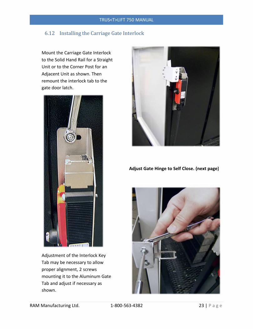
6.12 Installing the Carriage Gate Interlock
Adjust Gate Hinge to Self Close. (next page)
Mount the Carriage Gate Interlock to the Solid Hand Rail for a Straight Unit or to the Corner Post for an Adjacent Unit as shown. Then remount the interlock tab to the gate door latch.
Adjustment of the Interlock Key Tab may be necessary to allow proper alignment, 2 screws mounting it to the Aluminum Gate Tab and adjust if necessary as shown.
TRUS<T>LIFT 750 MANUAL
RAM Manufacturing Ltd. 1-800-563-4382 24 | P a g e
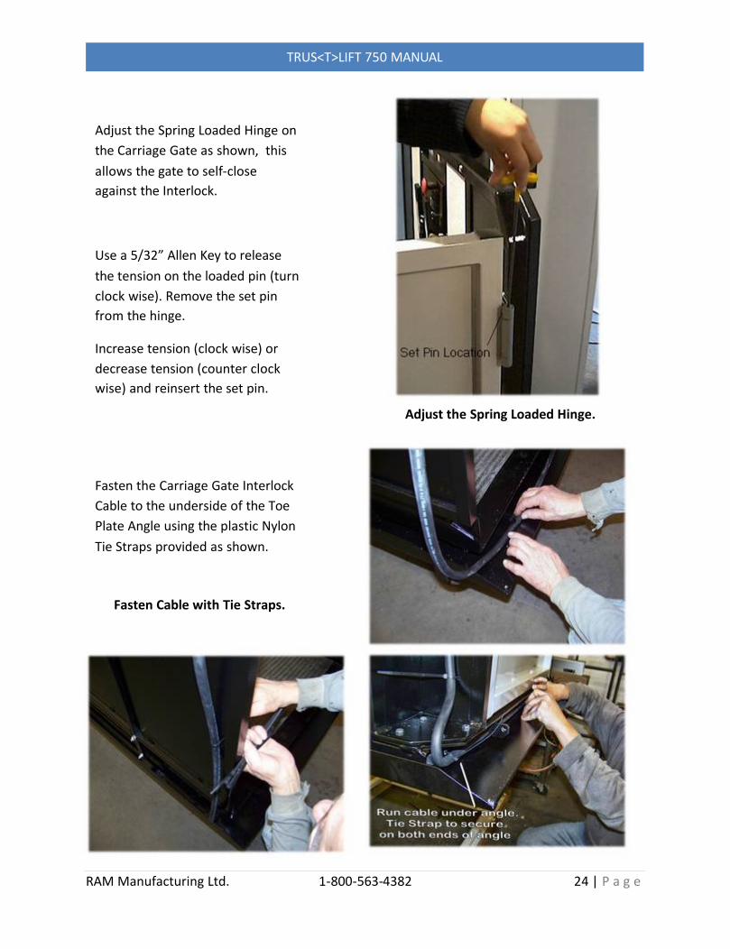
Adjust the Spring Loaded Hinge.
Fasten Cable with Tie Straps.
Adjust the Spring Loaded Hinge on the Carriage Gate as shown, this allows the gate to self-close against the Interlock.
Use a 5/32” Allen Key to release the tension on the loaded pin (turn clock wise). Remove the set pin from the hinge.
Increase tension (clock wise) or decrease tension (counter clock wise) and reinsert the set pin.
Fasten the Carriage Gate Interlock Cable to the underside of the Toe Plate Angle using the plastic Nylon Tie Straps provided as shown.

TRUS<T>LIFT 750 MANUAL
RAM Manufacturing Ltd. 1-800-563-4382 25 | P a g e
6.13 Mounting the Upper Landing Gate
Mount the Upper Gate to the threshold at the upper landing as shown.
Drill through the 4” X 4” Angle on the Upper Gate frame at suitable locations to provide adequate mounting holes for the angle, lag bolt or screw into place. OR Use a Polyurethane Adhesive to mount the threshold to the upper landing.
Use a Polyurethane Adhesive to mount the Upper Gate Post uprights to the existing structure as shown.
When using the Polyurethane Adhesive, adequate clamping and support must be in place until the adhesive sets properly. (NOTE CLAMP IN PICTURE)
Drill Through Both Angle Edges to Fasten Gate to Threshold.
Use Adhesive to Fasten Gateto Existing Structure.

TRUS<T>LIFT 750 MANUAL
RAM Manufacturing Ltd. 1-800-563-4382 26 | P a g e
Basic Wall Mounting
Using Lag Bolts (wood Lag Bolts are Supplied with Lift)
Section 7: Mounting the Tower to a Wall
On Commercial applications and Tall Tower installation you will be required to attach the tower to a wall or support. Your code requirements may vary so check with your governing authority.
2 - Proceed to attach tower to wall using Spacer Block (not provided) and Lag Bolts.
See Section 7.1 for details
3 - Fasten Base Legs to Ground.
See Section 5.5 for details

TRUS<T>LIFT 750 MANUAL
RAM Manufacturing Ltd. 1-800-563-4382 27 | P a g e
See Sections 7.2 & 7.3 for details
7.1 Installing the Spacer Block for Wall Mount

TRUS<T>LIFT 750 MANUAL
RAM Manufacturing Ltd. 1-800-563-4382 28 | P a g e
7.2 Spacer Block Placement
TRUS<T>LIFT 750 MANUAL
RAM Manufacturing Ltd. 1-800-563-4382 29 | P a g e
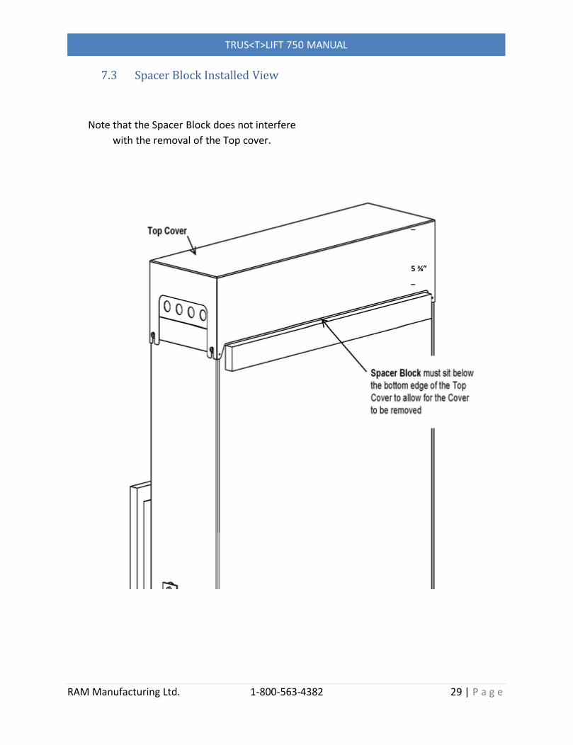
7.3 Spacer Block Installed View
Note that the Spacer Block does not interfere with the removal of the Top cover.
_
5 ¾”_
TRUS<T>LIFT 750 MANUAL
RAM Manufacturing Ltd. 1-800-563-4382 30 | P a g e
Section 8: Tall Tower Lifting Instructions
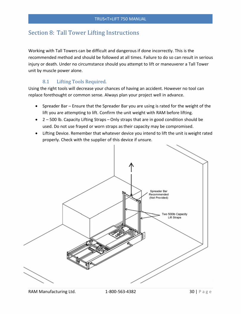
Working with Tall Towers can be difficult and dangerous if done incorrectly. This is the recommended method and should be followed at all times. Failure to do so can result in serious injury or death. Under no circumstance should you attempt to lift or maneuverer a Tall Tower unit by muscle power alone.
8.1 Lifting Tools Required.Using the right tools will decrease your chances of having an accident. However no tool can replace forethought or common sense. Always plan your project well in advance.
Spreader Bar – Ensure that the Spreader Bar you are using is rated for the weight of the lift you are attempting to lift. Confirm the unit weight with RAM before lifting.
2 – 500 lb. Capacity Lifting Straps – Only straps that are in good condition should be used. Do not use frayed or worn straps as their capacity may be compromised.
Lifting Device. Remember that whatever device you intend to lift the unit is weight rated properly. Check with the supplier of this device if unsure.

TRUS<T>LIFT 750 MANUAL
RAM Manufacturing Ltd. 1-800-563-4382 31 | P a g e
8.2 Locating the Lifting Straps
The lifting strap placement is critical. Failure to use the recommended locations can produce unpredictable results. Confirm proper placement before attempting lift.

TRUS<T>LIFT 750 MANUAL
RAM Manufacturing Ltd. 1-800-563-4382 32 | P a g e
8.3 Releasing the Lifting Straps
Once you have completed raising the unit you must attach the Base Legs to the Tower. This is done BEFORE you release the lifting straps. DO NOT ATTACH THE BASE LEGS TO THE GROUND AT THIS TIME. See Section 5 Base Leg Installation.

TRUS<T>LIFT 750 MANUAL
RAM Manufacturing Ltd. 1-800-563-4382 33 | P a g e
Section 9: Maintenance
9.1 Monthly Inspection:9.1.1 Inspect all gates/doors and ensure they are locked when the lift is not at the landing. Also check that the lift will not run unless the gates / doors are fully closed and locked once the platform is more than 2” (50mm) from the landing.9.1.2 Inspect the toe plate and ensure it is operating smoothly and moving into the up position when the lift leaves the lower landing
9.2 Annual Maintenance:The Trus <T> Lift should be inspected and maintained annually.
9.2.1 Inspect the drive nuts Compare the amount of movement in the drive nuts from side to side
and up and down without rotating the drive nut at all. If they feel overly sloppy or as though threads may be missing then they need to be replaced. Signs of bronze thread material or shavings are another indicator of worn lifting nuts. If the amount of movement is minimal spin the drive nuts by hand to check for resistance, if any resistance is felt or the drive nut binds then they must be replaced. Refer to Replacing the Drive Nuts Section 9.3
9.2.2 Inspect the drive screw Inspect the drive screw for any irregularities, sharp edges or foreign objects and dirt caught in the threads. Be sure no damage exists to the drive screw and that it is entirely clean of debris. Replace screw if damaged.
9.2.3 Clean and re-lubricate the drive screwIn order to lubricate the drive screw you must remove the main front panel and a carriage guide frame panel (Fig M1 and M2). Use a clean rag to wipe all of the grease off of the screw. Liberally apply Mobil SHC-460grease on the drive screw by hand.

TRUS<T>LIFT 750 MANUAL
RAM Manufacturing Ltd. 1-800-563-4382 34 | P a g e
9.2.4 Inspect the drive beltRemove the top cover and inspect the drive belt for wear. A small amount of black rubber bits below the belt is normal. If there is any significant sign of wear to the belt, replace.
9.3 Replacing the Drive Nuts
Should the main drive nut become worn or fail you will have to replace it. Note that both the Backup Drive Nut and Main Drive Nut are replaced at the same time. Never replace only one nut.
Note that the platform of the lift must be blocked up high enough for you to work under. Use the manual crank to lift the platform and guide frame and prop it up using a 2x4 or shoring device It is not necessary to remove the platform but can be done if you need more working space. The platform MUST BE SECURED with a chain or belt rated for a minimum of 1000 lbs. This is necessary in case the 2 x 4 slips while working under the platform.

TRUS<T>LIFT 750 MANUAL
RAM Manufacturing Ltd. 1-800-563-4382 35 | P a g e
9.3.1 Disconnect Power or Unplug the Lift.9.3.2 Un-assemble the Lift in the following order.
Remove the Top cover
Remove the GuideFrame Covers
Remove the
Front Panel
Remove the Back Panel

TRUS<T>LIFT 750 MANUAL
RAM Manufacturing Ltd. 1-800-563-4382 36 | P a g e
9.3.3 Remove the Break Block
9.3.4 Remove the Drive Belt
9.3.5 Block the Drive Shaft
9.3.6 Ensure that Drive Shaftis clear of Guide

TRUS<T>LIFT 750 MANUAL
RAM Manufacturing Ltd. 1-800-563-4382 37 | P a g e
9.3.7 Undo all Drive Nut Bolts Top & Bottom
9.3.8 Remove the Red Safety Bracket
9.3.9 Measure Distance from Bottom Nut to End of Screw
Make note of this measurement for later
9.3.10 Measure the Distance Between Nuts
Make note of this measurement for later
9.3.11 Pull Drive Shaft Forward and SpinOff Nuts

TRUS<T>LIFT 750 MANUAL
RAM Manufacturing Ltd. 1-800-563-4382 38 | P a g e
9.3.12 Clean Old Lubricantof Entire Screw. Use a twisting action to ensure proper cleaning
9.3.13 Apply New Lubricant to Screw and Drive Nuts
9.4 Spin On New Drive Nuts
9.4.1 Ensure Bottom Nut isthe Correct Distance from End of the Screw. Measure theDistance between Drive Nuts –
Ensure Proper Spacing. Usethe measurements you noted earlier.

TRUS<T>LIFT 750 MANUAL
RAM Manufacturing Ltd. 1-800-563-4382 39 | P a g e
9.4.2 Unblock the Drive Shaft
9.4.3 Ensure Bottom of ShaftAligns with Guide
9.4.4 Replace Safety Bracketand Tighten Drive Nut Bolts
Be sure to replace the lower limit switch rod
9.4.5 Replace Drive Belt

TRUS<T>LIFT 750 MANUAL
RAM Manufacturing Ltd. 1-800-563-4382 40 | P a g e
9.4.6 Replace Break Block
9.4.7 Power on the LiftTest Operation. Note that top cover switch must be depressed or lift will notoperate. Never attempt to operate the lift with the top cover off.
9.4.8 Reassemble the Lift
Replace the Back Panel
Replace the Front Panel
Replace the Guide Frame Covers
Replace the Top Cover (Ensure that Top cover switch is properly depressed or lift will not operate.)
Lower Platform
9.5 Maintenance Log:Please keep a record of all maintenance done on the lift in the maintenance log provided in Appendix C.
TRUS<T>LIFT 750 MANUAL
RAM Manufacturing Ltd. 1-800-563-4382 41 | P a g e
Section 10: Basic Trouble Shooting
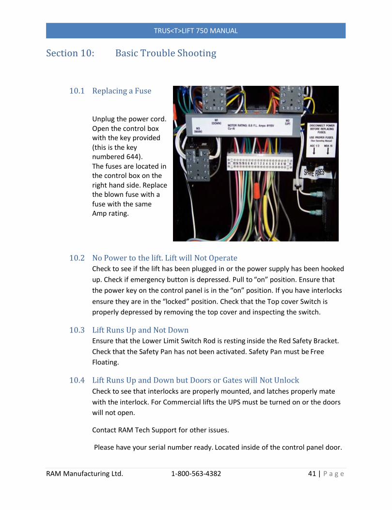
10.1 Replacing a Fuse
Unplug the power cord.Open the control box with the key provided (this is the key numbered 644).The fuses are located in the control box on the right hand side. Replace the blown fuse with a fuse with the same Amp rating.
10.2 No Power to the lift. Lift will Not OperateCheck to see if the lift has been plugged in or the power supply has been hooked up. Check if emergency button is depressed. Pull to “on” position. Ensure that the power key on the control panel is in the “on” position. If you have interlocks ensure they are in the “locked” position. Check that the Top cover Switch is properly depressed by removing the top cover and inspecting the switch.
10.3 Lift Runs Up and Not DownEnsure that the Lower Limit Switch Rod is resting inside the Red Safety Bracket.Check that the Safety Pan has not been activated. Safety Pan must be Free Floating.
10.4 Lift Runs Up and Down but Doors or Gates will Not UnlockCheck to see that interlocks are properly mounted, and latches properly mate with the interlock. For Commercial lifts the UPS must be turned on or the doors will not open.
Contact RAM Tech Support for other issues.
Please have your serial number ready. Located inside of the control panel door.

TRUS<T>LIFT 750 MANUAL
RAM Manufacturing Ltd. 1-800-563-4382 42 | P a g e
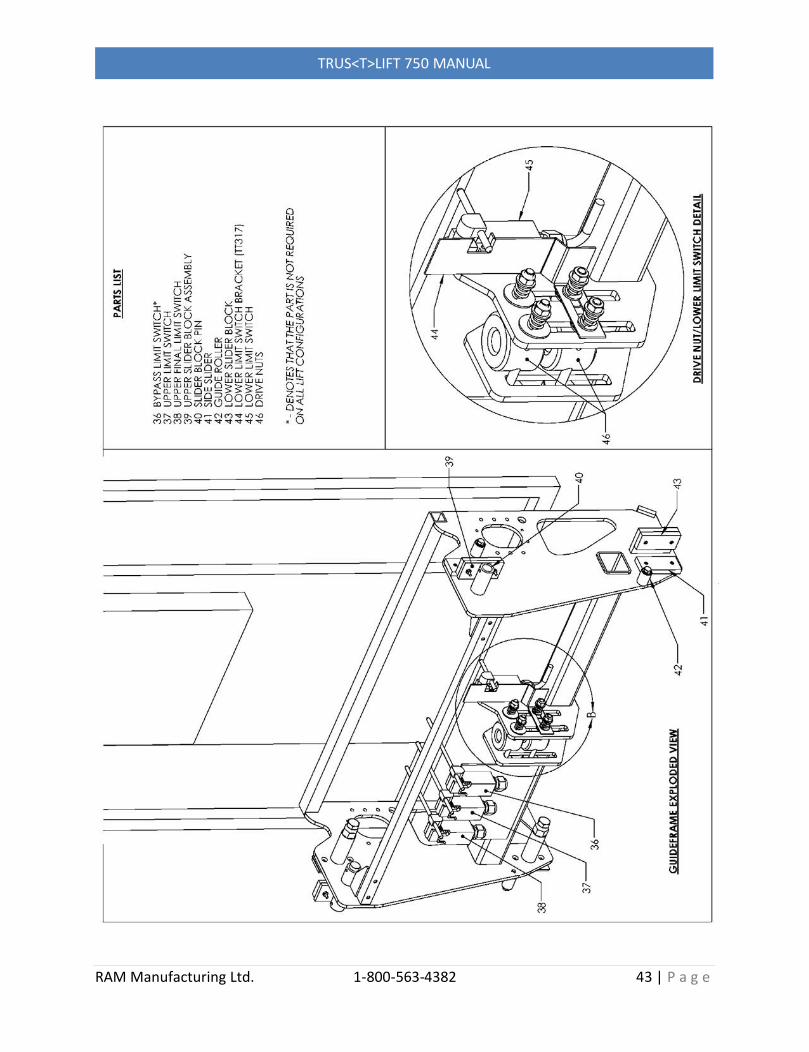
Appendix A: Trus <T> LIFT Assembly Drawings (with part numbers)
TRUS<T>LIFT 750 MANUAL
RAM Manufacturing Ltd. 1-800-563-4382 43 | P a g e
TRUS<T>LIFT 750 MANUAL
RAM Manufacturing Ltd. 1-800-563-4382 44 | P a g e
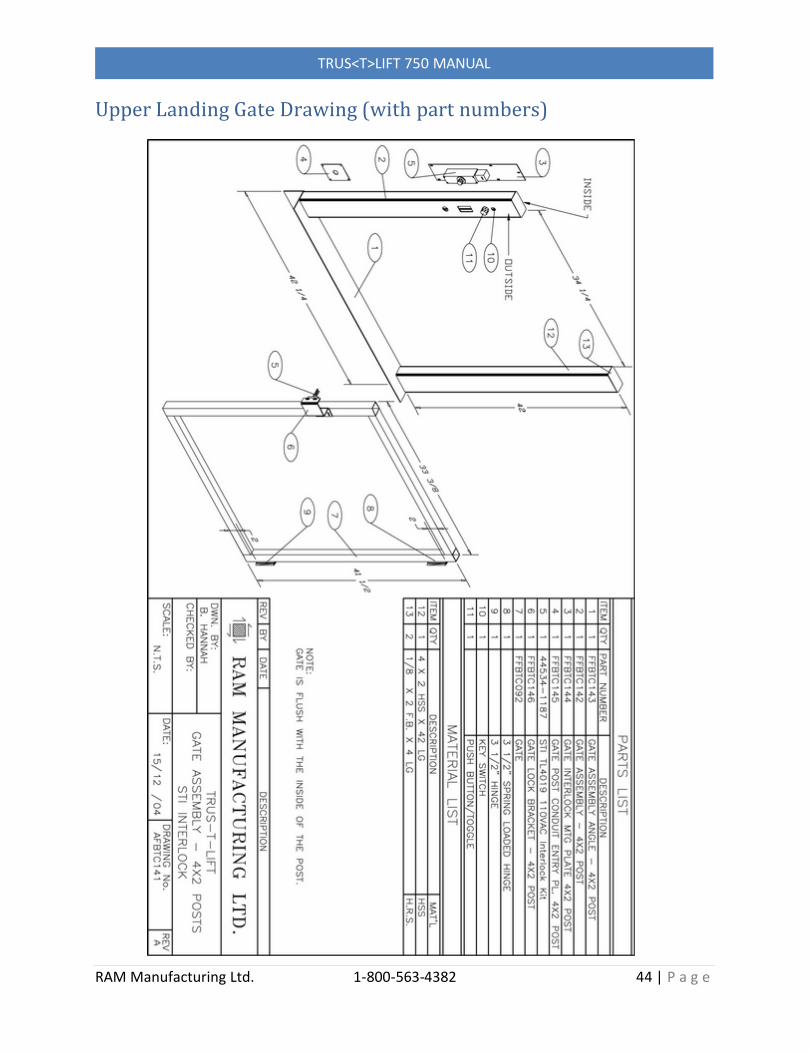
Upper Landing Gate Drawing (with part numbers)

TRUS<T>LIFT 750 MANUAL
RAM Manufacturing Ltd. 1-800-563-4382 45 | P a g e
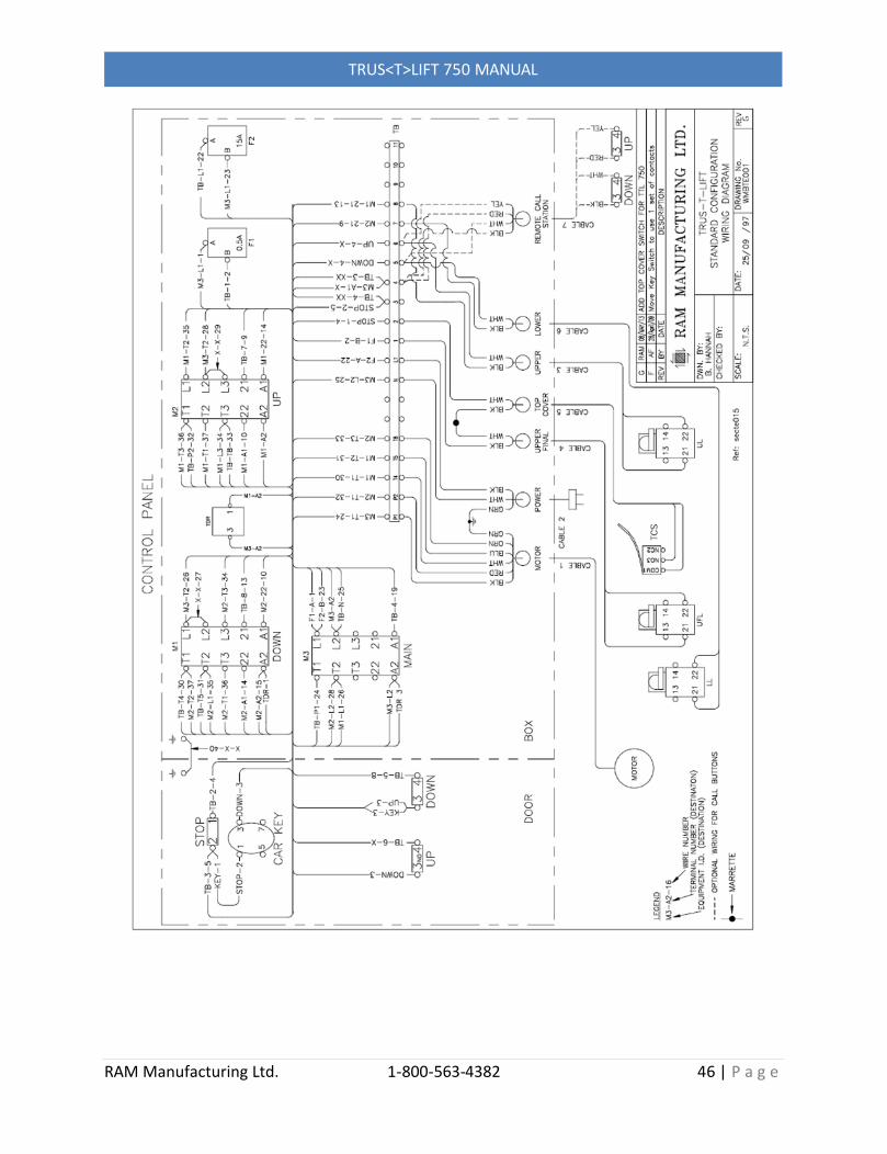
Appendix B: Basic Electrical DrawingNote: For lifts with options the electrical drawing specific to the options provided will be sent with the lift.
TRUS<T>LIFT 750 MANUAL
RAM Manufacturing Ltd. 1-800-563-4382 46 | P a g e

TRUS<T>LIFT 750 MANUAL
RAM Manufacturing Ltd. 1-800-563-4382 47 | P a g e
Appendix C: Maintenance Log
Date Description Signed