trunnion ball valve - iniciolomisa.com/images/stories/pdf/della_foglia_iom.pdf · trunnion ball...
TRANSCRIPT
TTRRUUNNNNIIOONN BBAALLLL VVAALLVVEE
TRUNNION PLATE
DELLA FOGLIA s.a.s. Viale Kennedy, 149 Tel. : +39 0331-602059 Fax : +39 0331-604249
e-mail : [email protected]
TN
INSTRUCTION HANDBOOK

INSTRUCTION HANBOOK
INTRODUCTION 2
TRUNNION BALL VALVE (Trunnion Plate) 1
INTRODUCTION 3 Section 1 4 Section 1/A: GENERAL SAFETY INSTRUCTIONS 4
1. Safety instruction for installation in hazardous area 4 2. Applicable standards and regulations 6
Section 1/B: STORAGE AND PRE-INSTALATION 7 1. Test to be carried out when the valve is received 7 2. Storage procedure 7
Section 1/C: INSTALLATION 9 1. Handling 9 2. Coupling with actuator. 10 3. Installation in environment with explosive atmospheres 10 4. Installation instruction 11 5. Start-up testing 12
Section 2 14 OPERATING INSTRUCTIONS 14
1 General operating instructions 14 2. Operating ball valves 14 3. Lock the valve 16 4. Vent and Drain 16 5. Emergency Seat-Stem Sealant injection 18
Section 3 20 MAINTENANCE 20
1. General Maintenance instruction 20 2. Stem Repair/Replacement 20 3. Major Overhaul 21 4. Re-Assembly 22
Section 4: 24 TROUBLE SHOOTING AND RISK ASSESSMENT 24
1 Trouble shooting 24 2.Risk Analysis 25
Section 5: 28 Drawings and Spare Parts 28
1. Exploded View 28 2 Commercial Drawings 29 3. Parts List 30
NOTES: Della Foglia has taken every care in collecting and verifying the documentation contained in this instruction and operating manual. Nevertheless Della Foglia sas does not provide any guarantees for this instruction manual. Della Foglia sas will not be responsible for any mistakes contained in it or for any damage either accidental or due to the use of this manual. The information herein contained is reserved property of Della Foglia sas and is subject to being modified without notice.
1 13-09-06 Rev.1 V.Bandera G.Caruso V.Bandera Rev Date Description Emitted by Verified Approved

INSTRUCTION HANBOOK
INTRODUCTION 3
INTRODUCTION This manual applies to side entry Trunnion ball valves, three bolted pieces body. The ball is fully supported by the ball plates. Valves are suitable for double block and bleed service. Drawings shown are typical. The design of specific valves may vary slightly from the drawings. Valves are furnished with the following functional characteristics:
− Antiblow-out stem according safety requirements. − Antistatic device. − Self relieving seats. − Spring energised seat for tight seal at low pressure together with wear and temperature
compensation. − Stem sealant injection. − Surface finish on the ball allows an high number of cycles with tight sealing. − Fire safe construction
Valves can be furnished with the following functional characteristics:
− Seat sealant injection. − Gear operated valve. − Hydraulic, Pneumatic or electric Actuator.
Joint Type: RF – FF - BW (WE) – RTJ – HUB END Service: Swett and Sour Gas, Oil, Gas, Chemical and Petrochemical plant, Sewage
Any possible functional failure due to wrong material selection made by the customer or due to customer specification requirements is not Della Foglia responsibility.
Design temperature range is established according to material characteristic; in no case it is possible to overtake this range. In case the temperature range is stated by the customer, they have to verify that this range is the actual ones.
It is customer responsibility to verify that valve materials are suitable for the actual service. Valve are built in accordance to PED requirements (when specified), Purchase Order and customer specification; It is not Della Foglia responsibility to verify P.O. or customer specification for PED compliance.

INSTRUCTION HANBOOK
SECTION 1/A: GENERAL SAFETY INSTRUCTION 4
Section 1 Section 1/A: GENERAL SAFETY INSTRUCTIONS
It is assumed that the installation, setting, commissioning, maintenance and repair works are carried out by qualified personnel and checked by responsible Specialists.
The Valves are designed in accordance with the applicable International rules an Client Specifications but the following Regulations must be observed in any case: − the general installation and safety regulations − the plant specific regulations and requirements − the proper use of personal protective devices (glasses clothing, gloves) − the proper use of tools, lifting and transport equipment
1. Safety instruction for installation in hazardous area
In case the valve must be installed in an HAZARDOUS AREA, as defined by the local Rules, it is mandatory to check if the nameplate of the valve specifies the appropriate degree of protection.
Della Foglia valves have been designed and manufactured according to 94/9/CE Directive (Atex). They are suitable for use in hazardous area classified against the risk of explosion due to the presence of gas and dust.
Every pressure equipment should be provided by a emergency pressure run-off, according to 97/23/CE directive (PED).
1.1 MARKING Located on the body of the Ball Valve, the API nameplate provides applicable information including size, pressure class, materials, seals pressure/temperature ratings and serial number. Reference to the serial number will expedite any request regarding your valve.
1 2 34 56 7 89 1011 12
13 14 15
API Nameplate

INSTRUCTION HANBOOK
SECTION 1/A: GENERAL SAFETY INSTRUCTION 5
1 Nominal valve size 2 Pressure class 3 Della Foglia job identification 4 Maximum operating pressure at maximum operating temperature 5 Maximum operating pressure at minimum operating temperature 6 Valve type 7 Serial number 8 Item number as in purchase order 9 Body material identification 10 Stem material identification 11 Ball material identification 12 Seat material identification 13 Purchase order identification 14 Tag Identification 15 Date of manufacture
Valves sell in EU have also CEE nameplate, providing information about Valve PED & Atex classification.
0038 = notified body for ATEX Quality assurance (Lloyd Register) II = group II (surface) 2 = category 2 apparatus G = explosive atmospheres caused by gas, mists or vapour D = explosive atmospheres caused by dusts Hazardous zone Categories according to 94/9/CE Directive Gas, mist or vapours Zone 0 1G Gas, mist or vapours Zone 1 2G Gas, mist or vapours Zone 2 3G Dust Zone 20 1D Dust Zone 21 2D
Dust Zone 22 3D
CEE Nameplate (PED & Atex)

INSTRUCTION HANBOOK
SECTION 1/A: GENERAL SAFETY INSTRUCTION 6
2. Applicable standards and regulations API Spec. 6D/ISO 14313 Specification for Pipeline Valves (Gate, Plug, Ball and Check Valves). API Spec. 6FA Specification for Fire Test for Valves . API Std. 607 Fire Test for Soft Seated Quarter-Turn Valves . API Spec. Q1 Specification for Quality Programs for the Petroleum and Natural Gas ASME B1.20.1 Pipe Threads, General Purpose . ASME B16.5 Pipe Flanges and Flanged Fittings . ASME B16.10 Face to Face and End to End Dimensions of Valves . ASME B16.11 Forged Fittings, Socket-Welding and Threaded . ASME B16.25 Buttwelding Ends . ASME B16.34 Valves-Flanged Threaded and Welding End . ASME B31.3 Chemical Plant and Petroleum Refinery Piping . ASME VIII, Div. I ASME boiler and pressure vessel code, section VIII, division 1: Rules for
construction of pressure vessels . MSS SP-25 Marking System for Valves, Flanges, Fittings and Unions . MSS SP-45 Bypass and drain connections . NACE MR01-75 Standard Material Requirements – Sulphide Stress Cracking Resistant-Metallic
Materials for Oilfield Equipment . ISO 9000: 2000 Quality System - Model for Quality Assurance in Design / Development,
Production, Installation and Servicing . ISO 5211-1 Part turn valve actuator attachment - Part 1: flange dimensions . BS 1503 Specification for steel forging (including semi-finished forged products) for
pressure purposes . BS 5351 Steel Ball Valve for Petroleum, Petrolchemical and Allied Industries . BS 6755: Part.1 Testing of Valves. Specification for production pressure testing requirements. BS 6755: Part.2 Testing of Valves. Specification for Fire-testing requirements . BS EN 10204 Metallic Products – Type of Inspection Documents PED (97/23/CE) Pressure Equipment Directive Atex (94/9/CE) Explosives Atmospheres Directive ASTM American Society of Testing Materials

INSTRUCTION HANBOOK
SECTION 1/B: STORAGE AND PRE-INSTALLATION 7
Section 1/B: STORAGE AND PRE-INSTALATION
1. Test to be carried out when the valve is received − Check that no damage has occurred during transport − Check the information on the nameplate: serial number and main characteristic (maximum pressure,
range of temperature allowed, class of protection). − Verify that valve is in open position. − Make sure all accessories have been received with the shipment, as described in the delivery
documentation.
ì2. Storage procedure The Valve leaves the factory in perfect condition, as guaranteed by an individual test certificate. In order to maintain these characteristics until the valve is installed on site, proper procedures must be taken for preservation during storage period.
Not performing the following procedures will invalidate the product guarantee.
2.1 GENERAL − Valves are shipped from the factory completed with end caps and preservation care. during storage do
not remove the valve from his original packing, until installation. If it’s not possible make sure internal parts of the valve (ball, seat, gaskets, etc.), are properly protected, and pay particular attention to end connections.
End Connection Cap

INSTRUCTION HANBOOK
SECTION 1/B: STORAGE AND PRE-INSTALLATION 8
− Before moving the valves make sure they are properly fixed and supported, in order to prevent damage. − Valves ha to be stored in a dry, clean indoor area, where hard particles, sand or dust can not be
introduced into the valve. Never pile up valve. − Possibly do not store valves in open air, if this is not possible protect them with suitable preservation oil
or other suitable product. Valves should never be exposed to direct action of weather agents.
2.2 LONG PERIOD STORAGE (more than one year) In addition to the instruction at point 2.1: − protect all internal parts of the valve with suitable preservation oil or other suitable product. − Carry out an opening / closing cycle at least once a year − Inspect the valve bore, valve surface, end connections in order to reveal any incipient corrosion.

INSTRUCTION HANBOOK
SECTION 1/C: INSTALLATION 9
Section 1/C: INSTALLATION All Della Foglia sas Ball Valves are bi-directional and may be installed for flow in either direction
Check the temperature and pressure range embossed on the nameplate, for the correct utilisation. Never overcome these limit ! In case of overcoming temperature and pressure limit contact immediately Della Foglia sas.
Using the valve in operating condition different from what reported in contract documents could damage valve and cause injury for people. Della Foglia sas is not responsible for improper use
1. Handling − Valve are furnished in open position, in order to minimize the effect of mechanical loads and impurities
on seats, gaskets, and other pressure parts. Before handling the valve, verify it is in open position. − Lift valve with sling suitable for its weight
Never use lever, actuator or gear operator to lift the valve
For correct valve transportation use all lifting lugs Valves weighting less than 250 kg have to be lifted fixing sling to ends connections.
− Ball Valves have to be handled with care. − Impacts, vibrations, and falling off could damage seats and pressure parts of the valve, causing leakages
or malfunctions.

INSTRUCTION HANBOOK
SECTION 1/C: INSTALLATION 10
2. Coupling with actuator.
Valve could be furnished without actuator. Adaptor plate and stem configuration have to be specified in contractual document.
Valves designed for use in potentially explosive areas must be equipped with actuators in the same class of protection.
Before starting actuator installation read carefully actuator instruction handbook, and follow manufacturer procedures and additional requirements.
− Make sure that joint surfaces are greased with silicon oil or equivalent before assembly. − Check the dimension of the top mounting details, paying particular attention to the protrusion of the valve
stem in order to avoid any axial thrust to internal parts of the valve and actuator. − Make sure no mating parts are forced − Verify adjustment of the open closed position stops. − Verify torque value of actuator.
3. Installation in environment with explosive atmospheres
Della Foglia Valves shall be installed and maintained according to the applicable rules regarding the non-electrical installations in hazardous area (other than mines), classified as zone 1 and 21.
User has to respect requirements of 94/9/CE Directive(Atex), and/or other national standards. − Installation operation has to be carried out in environment without explosive atmosphere. − Pay particular attention when using tools that could generate electrical arc, sparks, and other source of
ignition. − Avoid impact between valve surface and other object. Pay particular attention to rusted metallic objects.
Valve surface, in some application could reach high temperature. Make sure this temperature can not ignite gas, vapour, mist or dusts. If temperature is to high, insulate properly the valve.
Standard lifting lug Special lifting point

INSTRUCTION HANBOOK
SECTION 1/C: INSTALLATION 11
3.1 ENVIRONMENT WITH EXPLOSIVE DUSTS Please make sure that: − The joint surface with actuator are greased with silicon oil or equivalent before assembly − Periodically verify the quantity of dust deposited on the valve surface, and clean it if more than 5 mm. − Verify if less than 5mm of dust could be a source of ignition at operating temperature.
4. Installation instruction To avoid faults, breakdown and leakages , install the valve respecting recommendations at this point.
It is assumed that the installation is carried out by qualified personnel and checked by responsible Specialists. During design of pipeline is important to take proper measures to reduce mechanical load at valve ends, like bending, torsion, compressive force, vibration, due to pipe, equipments, etc. Do not employ valve if these forces exceed the values reported in Contractual Documents.
− Extract Valve from packaging immediately before start installation, or respect instruction at point 1/C 2
(“storage”). − Check that valve tag correspond to the tag needed. − Remove protection end cap. − Make sure the valve bore is free from impurity like sand or other hard particles. Never stroke the valve if
Bore is not properly clean. − Inspect valve internal parts. If there is any evident damage do not install valve − Verify that valve is in open position − Foreign material in the pipeline could damage the seating surface of the valve or even obstruct the
movement of the valve plug, ball, or disk so that the valve does not shut off properly. To help reduce the possibility of a dangerous situation from occurring, clean all pipelines before installing. Make sure pipe scale, metal chips, welding slag, and other foreign materials are removed.
Before connect valve to the pipeline, clean the pipeline and make sure no foreign material is present into the pipe.
− Della Foglia Ball Valves are intended for use in horizontal and vertical pipelines with the operating stem in any position. When valve is actuated, the most common method is with the actuator vertical and above the valve body. If horizontal actuator mounting is necessary, consider additional vertical support for the actuator.
− Orient Valve in piping to provide clearance and allow access to operator. Be sure to allow ample space above and below the valve to permit easy removal of the actuator or valve plug for inspection and maintenance
− Install the valve on the pipeline, following common procedures for every ends type. It’s very important to provide the valve with proper support.
− Prior to operating the valve from open position, the piping should be thoroughly flushed to prevent matter from damaging sealing surfaces.
Do not connect to Valve any additional equipment without authorization of Della Foglia sas.
4.1 FLANGED-END VALVES Flanged End Valves may be bolted into line using two open or boxed end wrenches. Power wrenches may be required for larger valves.

INSTRUCTION HANBOOK
SECTION 1/C: INSTALLATION 12
− Make sure the line flanges are properly aligned and will not distort or bind the valve ensuring a smooth gasket surface. Use new flange gaskets
− Bolt and nut threads should be lubricated to obtain proper loading of bolts. − Finger-tighten all nuts first. − Tighten bolts, using the crisscross method and torque each bolt to ANSI or gasket manufacture’s
specifications. Proper tightening will avoid uneven gasket loading and will help prevent leaks. It also will avoid the possibility of damaging, or even breaking, the flange. This precaution is particularly important when connecting to flanges that are not the same material as the valve flanges.
4.2 BUTT WELD-END VALVE Butt Weld-End Valves should by welded into the line by qualified welders, using qualified procedures. − Use solvent to clean grease or rust inhibitor from the gate and/or bore of the valve. − Make sure the line and valve weld bevels are properly aligned and will not bind the valve. − During welding let fresh air circulating within the valve bore (valve to be fully open). − Extreme caution should be taken regarding excess welding temperature to prevent damage to sealing
components of the valve. Keep valve temperature in the seat region below the maximum design temperature of the valve. Body temperature must not exceed 200°C in any point beyond 3” from the weld.
− Avoid rapid application of excess welding material. − Keep the valve in the “Full Open” position until the line has been thoroughly cleaned of weld slag in the
valve bore and line (by pigging and/ or flushing) before changing the position of the ball.
5. Start-up testing When Della Foglia ball valves are installed in a piping system that requires hydrostatic testing of the adjoining pipe. Follow these procedures to minimize any damage that could occur to the sealing surfaces and seat seals inside the valve: − carry out at least one opening-closing cycle, without pressure on pipeline (∆p = 0 barg). − The valve should be in a fully open position when the injection of test fluid begins. This will allow any
pipeline debris to be flushed through the valve bore and out of the piping. − Once the piping system has been purged of debris and the system has been filled completely with the
test fluid, the ball should be placed in the partially open position to allow test fluid into the body cavity of the valve.
− Upon completion of the hydrostatic testing, the valve should be returned to the fully open position before removing the test fluid from the piping system. The test fluid in the body
− cavity can be drained through the body drain port located in the lower portion of the valve body. (See Draining Valve).
− Close the valve body bleed fitting and return the valve to the required operating position, either fully open or fully closed.
5.1 TESTING FLUID Testing fluid has to be compatible with service fluid and characteristic of pipeline. Make sure to avoid any dangerous chemical reaction
Test generally could be performed using water with anti-corrosive additive or gas nitrogen. After installation and system testing, the valve should be drained to remove test fluid.

INSTRUCTION HANBOOK
SECTION 1/C: INSTALLATION 13
5.2 HYDROSTATIC SHELL TESTING Pressure during Shell Test has not to exceed 1.5 maximum pressure reported on nameplate. Usually shell test is performed with ball positioned at 45° (partially open)
5.3 HYDROSTATIC SEAT TEST Pressure during Hydrostatic seats test has not to exceed 1.1 maximum pressure reported on nameplate. Ball has to be fully closed
5.4 FUNCTIONAL TEST Functional test has to be performed at maximum pressure, reported on nameplate.
INSTRUCTION HANBOOK
SECTION 2 :OPERATING INSTRUCTION 14
Section 2 OPERATING INSTRUCTIONS
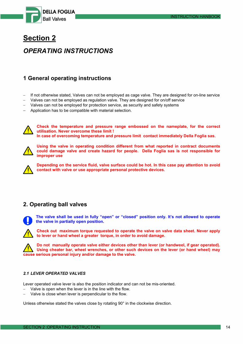
1 General operating instructions − If not otherwise stated, Valves can not be employed as cage valve. They are designed for on-line service − Valves can not be employed as regulation valve. They are designed for on/off service − Valves can not be employed for protection service, as security and safety systems − Application has to be compatible with material selection.
Check the temperature and pressure range embossed on the nameplate, for the correct utilisation. Never overcome these limit ! In case of overcoming temperature and pressure limit contact immediately Della Foglia sas.
Using the valve in operating condition different from what reported in contract documents could damage valve and create hazard for people. Della Foglia sas is not responsible for improper use
Depending on the service fluid, valve surface could be hot. In this case pay attention to avoid contact with valve or use appropriate personal protective devices.
2. Operating ball valves
The valve shall be used in fully “open” or “closed” position only. It’s not allowed to operate the valve in partially open position. Check out maximum torque requested to operate the valve on valve data sheet. Never apply to lever or hand wheel a greater torque, in order to avoid damage.
Do not manually operate valve either devices other than lever (or handweel, if gear operated). Using cheater bar, wheel wrenches, or other such devices on the lever (or hand wheel) may
cause serious personal injury and/or damage to the valve.
2.1 LEVER OPERATED VALVES Lever operated valve lever is also the position indicator and can not be mis-oriented. − Valve is open when the lever is in the line with the flow. − Valve is close when lever is perpendicular to the flow. Unless otherwise stated the valves close by rotating 90° in the clockwise direction.

INSTRUCTION HANBOOK
SECTION 2 :OPERATING INSTRUCTION 15
Gear bottom sight
2.2 GEAR OPERATED VALVES To open /close gear operated valves rotate the handweel as shown in the figure below. On the top of gear box there is a position indicator.
How to re-orientate the gear operation
a. Single stem key gear
1. Unscrew the operator stud nuts (49) and remove the operator, taking care not to damage the stem key (40)
2. Unscrew the screws (56) and remove the adapter plate (18), taking care not to damage the stem or adaptor plate alignment pin.
3. Unscrew the screws (21) and, pulling the stem (3), remove cover (24). 4. Remove the stem (3) frome the cover (24). Be carefull in handling, in
order not to damage orings an gaskets. 5. Re insert the stem into the body. Be sure it is turned 180° in comparison
to the position it had before disassembly. 6. Lubricate all moving metal contact surfaces. 7. Follow backward the instructions to reassembly the valve. Be carefull in
A Vista View

INSTRUCTION HANBOOK
SECTION 2 :OPERATING INSTRUCTION 16
Gear bottom sight
order not to damage orings an gaskets.
b. Double stem key gear 1. Unscrew the operator stud nuts (49) and remove the operator, taking
care not to damage the stem key (40). 2. Turn 180° the operator. 3. Re assembly the operator.
2.3 ACTUATED VALVES To operate actuated valve, follow indication on actuator instruction handbook. To reorientate the follow the instructions of point 2.2 – how to reorientate the gear operation.
3. Lock the valve If requested, valves can be locked in a position by means of a padlock.
4. Vent and Drain Unless otherwise stated, the Della Foglia Ball Valve is provided with two fittings in the body cavity. The vent fitting in the top of the body above and a drain plug in the bottom of the body.
Never attempt to open drain and/or vent fittings while the valve is subjected to line pressure. Care should be taken to ensure that exhaust ports are directed away from personnel.

INSTRUCTION HANBOOK
SECTION 2 :OPERATING INSTRUCTION 17
If stated in contractual documents, valves could not have drain and vent fittings. Sometimes instead standard drain and vent fittings, ball valves could have special drain and vent valve or flanged joints.
4.1 BLOCK AND BLEED Block and bleed operation is applied in order to: − Verify integrity of both seats − Allow draining and/or flushing of the valve body cavity − Absolute prevention of downstream leakage to assure safety of downstream activities Block and Bleed procedure:
Drain fitting Vent valve
Special Vent Valve Flanged drain and vent

INSTRUCTION HANBOOK
SECTION 2 :OPERATING INSTRUCTION 18
− Operate valve to the full open/full closed position as desired. − Using an appropriate tool turn the head of vent fitting to release body cavity pressure. − Continue venting until body pressure reaches atmospheric pressure.
During Block and Bleed may be released flammable gas. Make sure to prevent any source of ignition. Take care to assure exhaust port are directed away from personnel
4.2 DRAINING Draining can be accomplished using the bleed plug in the bottom of the body.
Never open any fitting without verifying that the body is not pressurised
5. Emergency Seat-Stem Sealant injection
Della Foglia Ball Valves are designed for long term operation without routine maintenance. Regular injection of sealant is expressly not recommended.
Della Foglia Ball Valves have the provision (when specified) for emergency seat and/or stem sealant injection. This feature provides a means for emergency seal of a damaged sealing surface using sealant. − Injection sealant in the upstream seat fitting will provide complete sealing inmost downstream leakage
situations. − Injection sealant in stem zone will provide complete sealing in stem leakage situations. − Operation of the valve after sealant injection usually requires re-injection of sealant.

INSTRUCTION HANBOOK
SECTION 2 :OPERATING INSTRUCTION 19
5.1 EMERGENCY SEALANT INJECTION PROCEDURE − Remove the sealant fitting safety cap
Watch the fitting body to insure that it does not turn while turning the cap. Do not attempt removal of the fitting while the valve is subjected to line pressure. A back up wrench on the fitting body may be required
− Use an appropriate grease gun and sealant. Use only grease guns, which are equipped with pressure
gages. Do not exceed the valve maximum allowable working pressure. − Inject sealant into the upstream sealant fittings, while observing leakage. − Inject sealant only sufficient to eliminate leakage. Continued injection is wasteful and contaminates the
flow stream. − Hold for at least 3 minutes. Re-pressurize, as needed.

INSTRUCTION HANBOOK
SECTION3 : MAINTENANCE 20
Section 3 MAINTENANCE
1. General Maintenance instruction
It is assumed that maintenance is carried out by qualified personnel and checked by responsible Specialists.
Valve could be operated many times during their life, or they could be inoperative for long period. So is advisable a preventive maintenance depending on service. However is recommended to check periodically torque requested to operate the valve, and verify leakages.
Without a suitable maintenance plan valve could suffer a damage. Della Foglia is not responsible for faults and every kind of injury due to lack or absence of maintenance.
Usually fails appears immediately after installation or start-up. Pay particular attention to valves in this situation. Generally during service fault are less frequent.
Never try to open any pressure part of the valve before verifying the valve is not subjected to line pressure.
2. Stem Repair/Replacement The following procedure may be used to replace stem and gland seals. Following operation have to be done in suitable workshop, and in greatest cleanliness. When requested in contractual documents, Stem disassembly can be performed while the valve is in line, performing Block and Bleed Procedure, as defined in 2, 2.3 Number indicated between bracket are the components position (see customer drawing)
2.1 STEM DISASSEMBLY PROCEDURE − Unscrew operator stud nut (49) and remove the operator, taking care not to damage the stem key (40). If
the valve is lever operated remove the wrench. − Unscrew the screws (56) and remove the adapter plate (18), taking care not to damage the stem or
adaptor plate alignment pin. − Unscrew the screws (21) and, pulling the stem (3), remove cover (24). − Remove the stem (3). − Remove stem o-ring (8a) and cover o-ring (26). − Remove gaskets (8) (25), and stem bearing (35). − Remove stem thrust washer (120)
2.2 INSPECTION AND REPLACEMENT OF COMPONENTS − Thoroughly clean all metallic components with a suitable solvent

INSTRUCTION HANBOOK
SECTION3 : MAINTENANCE 21
− Inspect all components for signs of wear or damage. Pay particular attention to sealing and bearing areas.
− Replace all damaged or defective components. − It is recommended that all seal components be replaced since defects cannot be readily determined by
inspection.
3. Major Overhaul Following operation have to be done in suitable workshop, and in greatest cleanliness. Lifting equipment suitable for the weight of the valve and components is required. No special tools are required.
3.1 SEAT/CLOSURE DISASSEMBLY PROCEDURE − Turn the valve to half open position and open body vent valve to insure that there is no trapped pressure
prior to removing the valve from the line. − Turn the valve to closed position − Remove the stem assembly according to procedure at point 1.1 − Remove the body nuts except for two nuts on each closure, 180° apart. − Turn the valve on end, on an even, level surface, taking care not to damage the faces of the valve. − Remove the two nuts retaining the upper closure and carefully lift closure observing seat. Seat should
remain with closure. Do not allow seat to fall and damage ball. − Turn closure over and place on even, level surface, protecting end face. − Turn ball (4) in close position, and lift it with proper slings. Paying attention to trunnion plate (27). Take
car not to damage ball and body (1) surfaces.
− Remove remaining nuts and lift body from assembly − Remove all o-ring (6a - 20) and gaskets (6 - 20d). − Pry seats from closures − Remove seat springs (9b) from closures. − Remove trunnion plate from ball and remove bearing spacer (122). − Remove trunnion bearings (33) from trunnion plate.
3.2 INSPECTION AND REPLACEMENT OF COMPONENTS − Thoroughly clean all metallic components with a suitable solvent. − Inspect all components for signs of wear or damage. Pay particular attention to sealing and bearing
areas. − Replace all damaged or defective components. − It is recommended that all seal components be replaced since defects cannot be readily determined by
inspection. − Contact Della Foglia sas, if some metallic part shows signs of corrosion.

INSTRUCTION HANBOOK
SECTION3 : MAINTENANCE 22
4. Re-Assembly − Lubricate all moving metal contact surfaces such as seat pockets and stem housing. − Lightly lubricate all seals gasket and thrust washers. − Install o-rings (6a-8a-20-26) and gaskets (6-8-20d-25) and verify they are properly placed. − Install trunnion bearings (33) on trunnion plate (27); Stem bearing (35) on cover (24), and stem thrust
washer on stem(3). − Place one end connection on a flat level surface with the ball end up. Protect the end face. − Install seat springs ( 9b) in the body holes. − Place seat on closure, taking care not to damage seat inserts (5b) and seat o-ring (20). − Even force must be applied to install the seat ring in the closure. Do not use hammer. Keeping seat
aligned with closure, press it down. − Repeat operation on other closure − Install trunnion plates (27) on ball(4), with ball bore parallel to plates. Rotate plates to assure free,
smooth operation without binding and orient them vertically. − Lift ball, using proper slings, taking care plates not to fall. − Lower Ball/plates assembly onto installed seat, carefully aligning dowel pins with holes in closure face. − Lower the body over the ball, taking care not to damage seal angle on body or ball surfaces. Carefully
align the stem hole in the body with the drive slot in the ball − Lower the closure onto the body, carefully aligning dowel holes in closure whit dowel pin in trunnion
plate. When lowering the closure, insure that the seat ring does not fall and damage ball. − Install body and seat fittings − Install all of the body nuts and tighten both sides evenly with appropriate torque (See following table).
Eventually install lugs and legs.

INSTRUCTION HANBOOK
SECTION3 : MAINTENANCE 23
− Insert stem (3) into the body, making sure it’s aligned with the drive slot in the ball. − Install cover (24), paying attention not to damage o-rings. Insert cover screws and screw them. − Install adapter plate(18), properly aligned. Insert screws and screw them. − Insert stem key (40) in stem slot − Install operator and verify smooth operation of the valve and adjustment of the open/closed position
stops.

INSTRUCTION HANBOOK
SECTION4 : TROUBLE SHOOTING AND RISK ASSESMENT 24
Section 4: TROUBLE SHOOTING AND RISK ASSESSMENT
1 Trouble shooting The scope of this part of the manual is to provide information about most common faults and trouble that user could meet during valve operating life.
Before execute any of action reported in this chapter, read carefully the whole manual, and follow all the recommendations. It is assumed that all operations are carried out by qualified personnel and checked by responsible Specialists. Any possible functional failure due to wrong material selection made by the customer or due to customer specification requirements is not Della Foglia responsibility.
TROUBLE CAUSES CONSEGUENCES ACTION
Leakage is occurring around stem
Damaging of O-ring and Gasket in stem zone, due to corrosion, aggressive environment, abnormal wear.
Developing gas could give rise to explosive atmosphere.
Follow instruction at Point 3 2.1 for stem disassembly and, if necessary, replace o-rings and gaskets. If stem or cover shows signs of corrosion, contact Della Foglia sas. In order to contain leakages for a short period, execute an emergency sealant injection, following instruction at point 5.1
The Grease fitting or Bleed/vent plug is leaking.
The safety cap or bleed/vent plug screw is loose.
Developing gas could give rise to explosive atmosphere.
Tighten the safety cap or bleed/vent plug screw.
The valve is leaking around closure to body joint.
Body seal is damaged Developing gas could give rise to explosive atmosphere.
Insure that the body nuts are tightened properly. Call Della Foglia sas if leakage persists.
The valve seats will not seal.
Damaging of seat inserts or ball, due to hard particles (sand, metal chips, etc.) in fluid, corrosion, aggressive fluid, lack of maintenance.
Downstream leakage in the pipeline
Follow instruction at Point 3 3.1 for body and closure disassembly and, if necessary replace seat inserts. If Ball surfaces is damaged or defective, contact Della Foglia sas.
The valve will not open or close.
Ball is blocked by some hard particle
Impossible to operate valve
Remove Valve from line, and if necessary execute maintenance following procedure at point 3.1. Never try to operate the valve with a extra-torque: It could lead to stem breakage.

INSTRUCTION HANBOOK
SECTION4 : TROUBLE SHOOTING AND RISK ASSESMENT 25
2.Risk Analysis
RISK CATEGORY RISK CAUSES CONSEGUENCES PRECAUTION CORRECTIVE ACTION
Handling / transportation Mechanical load on valve Objects piled up on valve Damaging of pressure parts
and fitting. Follow handling recommendations
Not Install damaged valve. Inspect valve at arrival
Handling / transportation Fall of valve Damaging of pressure parts
and fitting. Follow handling recommendations
Not Install damaged valve. Inspect valve at arrival
Storage / installation Inclusion of foreign material Storage in a non clean area Damaging of seals and
other pressure parts Follow storage procedure Inspect valve before installation, and remove any foreign material
Installation Mechanical load Flange not aligned with valve
High bolts stresses. Valve breakage Verify flanges alignment Contact Della Foglia sas
Installation Additional fittings not allowed
High mechanical load. Risk of rupture
Never connect to valve any additional fitting Contact Della Foglia sas
Maintenance Uncorrect Maintenance Non original spare parts Leakages, Damaging of pressure parts
Use only Della Foglia Spare Parts Contact Della Foglia sas
Maintenance Uncorrect Maintenance Personnel not properly trained
Leakages, Damaging of pressure parts
Maintenance operations must be carried out by qualified personnel.
Contact Della Foglia sas
Maintenance Lack of maintenance Plain of maintenance not suitable
Leakages, Damaging of pressure parts
Follow proper maintenance plan Contact Della Foglia sas
Maintenance Source of ignition Improper tools or operation Explosion and/or fire Use only tools suitable for explosive atmospheres
Maintenance Lubricant Lubricant containing aggressive substances
Leakages, Damaging of sealing Use only suitable lubricants Contact Della Foglia sas

INSTRUCTION HANBOOK
SECTION4 : TROUBLE SHOOTING AND RISK ASSESMENT 26
n Open valve pressure parts Unscrew vent or drain fitting when valve is in pressure. Unscrew body nuts
Serious people injury Never open valve pressure parts without assuring they are not pressurized
Contact Della Foglia sas
Operation Pressure limit overcome within 10%. Valve position “fully close”
Error in plant regulation Valve tested at 1,1 maximum pressure. No consequences.
Install relief valve for the entire plant
Operation Pressure limit overcoming over 10%. Valve position “fully close”
Error in plant regulation Seat leakages Install relief valve for the entire plant
Major Overhaul of the valve. Contact Della Foglia sas
Operation Pressure limit overcome within 50%. Valve “partially open”
Error in plant regulation Valve tested at 1,5 maximum pressure. No consequences.
Install relief valve for the entire plant
Operation Pressure limit overcome over 50%. Valve “partially open”
Error in plant regulation High bolts stresses. Valve breakage. Leakages
Install relief valve for the entire plant
Major Overhaul of the valve. Contact Della Foglia sas
Operation Valve surface temperature > 38°C
High fluid temperature, or hot environment
People injury when in contact with valve.
Temperature control. Valve insulation Personal protecting devices
Operation Surface temperature beyond dust ignition limit
High fluid temperature, or hot environment Explosion/fire Temperature control. Valve
insulation. Clean dust periodically
Operation Valve temperature beyond upper design limit
High fluid temperature, or hot environment
Leakages, Damaging of sealing, Decreasing of material strength
Never employ valve beyond temperature limits
Major Overhaul of the valve. Contact Della Foglia sas
Operation Valve temperature beyond lower design limit
Low fluid temperature, or cold environment.
Leakages, Damaging of sealing, material embrittlement
Never employ valve beyond temperature limits
Major Overhaul of the valve. Contact Della Foglia sas
Operation Corrosion of Valve internal parts
Fluid characteristic different from what reported in valve data sheet
Valve Lifetime reduction. Leakages, Damaging of internal parts
Valve designed for specific operating conditions. Never employ with different fluids
Contact Della Foglia sas
Operation Corrosion of Valve internal parts
Environment characteristics different from what reported in valve data sheet
Valve Lifetime reduction. Leakages, Damaging of external parts and fittings. Leakages
Valve designed for specific operating conditions. Never employ in different environments
Contact Della Foglia sas

INSTRUCTION HANBOOK
SECTION4 : TROUBLE SHOOTING AND RISK ASSESMENT 27
Operation Erosion of valve internal parts
Hard particles in fluid not predicted.
Valve Lifetime reduction. Leakages, Damaging of internal parts
Fluids with hard particles require valve with metal seat inserts
Contact Della Foglia sas
Operation Pipeline vibration Rapid pressure variation High bolt stress. Fatigue stress Control pipeline vibration
Operation Bending Valve non properly supported. Flange not aligned
Mechanical load on valve. High bolt stresses
Limit external loads according to contractual documents
Operation Compressive stress on valve Line thermal expansion Mechanical load on valve.
High body/closure stresses
Limit external loads according to contractual documents
Electric charge Electromagnetic induction, leakage current, static discharge.
Sparks, electric arc and other sources of ignition
Valve antistatic construction. Connect valve with ground and pipeline.
External Risk / Calamity Seismic Bolts overload Standard Plant
countermeasures Contact Della Foglia sas
External Risk / Calamity Explosions Bolts overload Valve is Fire Safe. Standard
Plant countermeasures Contact Della Foglia sas
External Risk / Calamity Fire Sealing damage, leakages,
fire propagation Valve is Fire Safe. Standard Plant countermeasures Contact Della Foglia sas

INSTRUCTION HANBOOK
SECTION5 :DRAWINGS AND SPARE PARTS 28
Section 5: Drawings and Spare Parts
1. Exploded View Drawings shown are typical. The design of specific valves may vary slightly from the drawings.
CLOSURE
BODY
LIFTING
TRUNNION PLATE
TRUNNION PLATE
SEAT
SEAT
STEM
STEM KEY
CLOSURE
COVER
ADAPTER PLATE
LEG
LEG
BALL

INSTRUCTION HANBOOK
SECTION5 :DRAWINGS AND SPARE PARTS 29
2 Commercial Drawings

INSTRUCTION HANBOOK
SECTION5 :DRAWINGS AND SPARE PARTS 30
3. Parts List Spare Parts Part No. Part Name Particolare 1 BODY CORPO 2 BODY END TERMINALE 3 STEM STELO 4 BALL SFERA
5 SEAT RING ANELLO SEGGIO 5b SEAT INSERT INSERTO SEGGIO 6 BODY GASKET GUARNIZIONE CORPO 6a BODY O-RING O-RING CORPO 8 STEM GASKET GUARNIZIONE STELO 8a STEM O-RING O-RING STELO
9b SEAT SPRING MOLLA SEGGIO 14 BODY STUD TIRANTE CORPO 15 BODY STUD-NUT DADO PER TIRANTE CORPO 18 ADAPTER PLATE FLANGIA MOTORE
20 SEAT O-RING O-RING SEGGIO 20d SEAT GASKET GUARNIZIONE SEGGIO
21 COVER CAP SCREW VITE FLANGIA PREMITRECCIA 24 COVER FLANGIA PREMITRECCIA
25 COVER GASKET GUARNIZIONE FL. PREMITRECCIA 26 COVER O-RING O-RING FL. PREMITRECCIA
27 TRUNNION PLATE PIASTRA SFERA 33 TRUNNION BEARING BOCCOLA PIASTRA 35 STEM BEARING BOCCOLA STELO
40 STEM KEY CHIAVETTA STELO 41 OPERATOR PIN SPNA OPERATORE 42 COVER PIN SPINA FLANGIA PREMITRECCIA 45 OPERATOR OPERATORE DI MANOVRA 48 OPERATOR STUD TIRANTE OPERATORE 49 OERATOR STUD-NUT DADO PER TIRANTE 56 ADAPTER PLATE CAP SCREW VITE FLANGIA MOTORE 60 DRAIN PLUG TAPPO DI DRENAGGIO 61 STEM GREASE INJECTION FITTING INGRASSATORE STELO 65 ANTISTATIC DEVICE SPRING MOLLA DISPOSITIVO ANTISTATICO 66 BLEEDER SFIATO 68 (*) SEAT GREASE INJECTION FITTING INGRASSATORE SEGGIO 68a (*) CHECK VALVE VALVOLA DI NON-RITORNO 69a LIFTING LUGS ASOLA DI SOLLEVAMENTO 71 SUPPORT FEET PIEDE DI SUPPORTO 81 TRUNNION PLATE PIN SPINA PIASTRA
120 STEM THRUST WASHER RONDELLA DI SPINTA STELO 121 KEY PIN SPINA CHIAVETTA
122 BEARING SPACER RONDELLA 169 (*) SEAL GREASE O-RING O-RING TENUTA GRASSO
Recommended Spar Parts
(*) When Required By Agreement
INSTRUCTION HANBOOK
SECTION5 :DRAWINGS AND SPARE PARTS 31
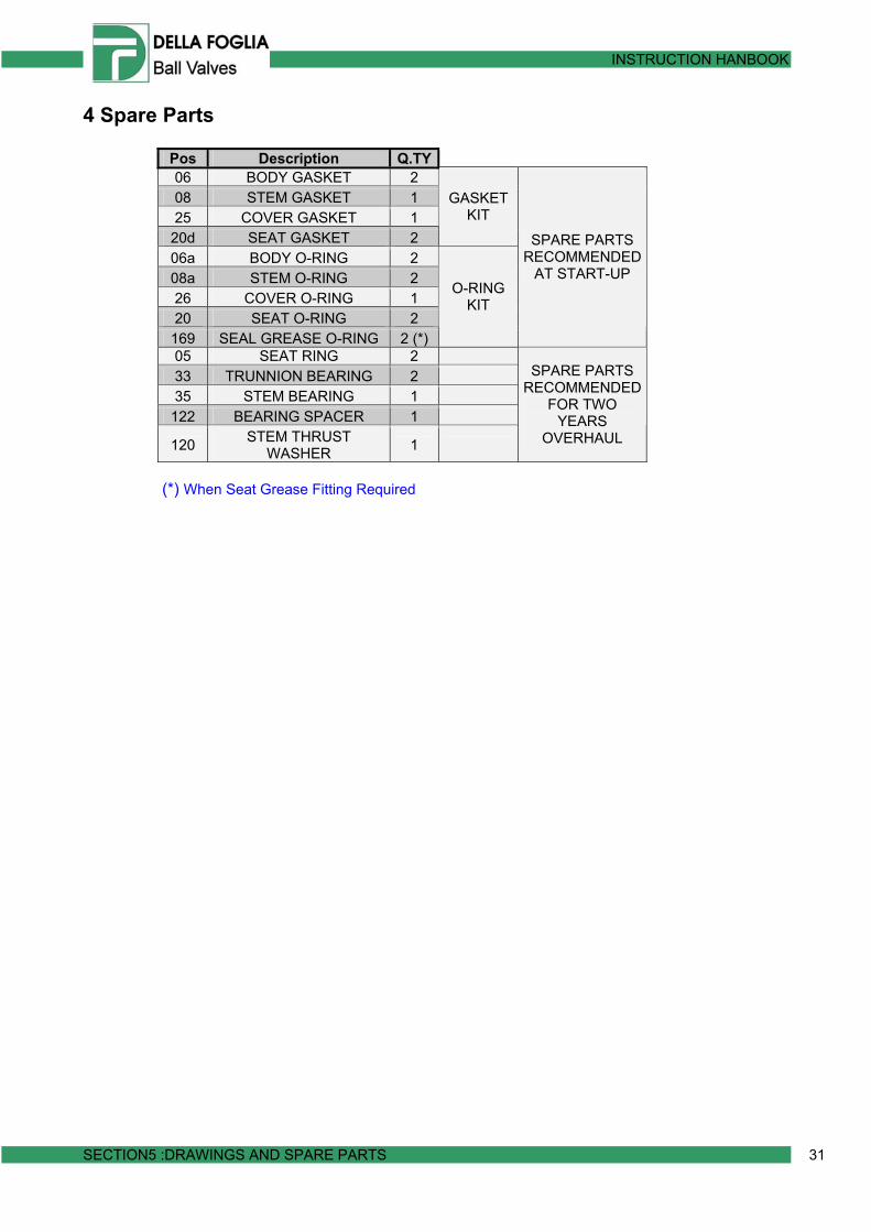
4 Spare Parts
Pos Description Q.TY 06 BODY GASKET 2 08 STEM GASKET 1 25 COVER GASKET 1
20d SEAT GASKET 2
GASKET KIT
06a BODY O-RING 2 08a STEM O-RING 2 26 COVER O-RING 1 20 SEAT O-RING 2
169 SEAL GREASE O-RING 2 (*)
O-RING KIT
SPARE PARTS RECOMMENDED
AT START-UP
05 SEAT RING 2 33 TRUNNION BEARING 2 35 STEM BEARING 1
122 BEARING SPACER 1
120 STEM THRUST WASHER 1
SPARE PARTS RECOMMENDED
FOR TWO YEARS
OVERHAUL
(*) When Seat Grease Fitting Required