true force keyboard - deep blue: home
TRANSCRIPT

True Force Keyboard Force-Reflecting Electronic Musical Instrument Interface
ME 450 Winter 2006 April, 18th 2006
Team 1 Franklin Jen
Prashanth Gururaja Robert Middleton
Stanley Shea
Sponsor: Professor Brent Gillespie Section Instructor: Professor Brent Gillespie

TABLE OF CONTENTS
Executive Summary 1
1 Abstract 2
2 Motivation & Problem Definition 2
3 Background 2
3.1 History of Keyboard Instruments 2
3.2 Musical Nomenclature 3
3.3 Acoustic Piano Action 3
3.4 Electronic Piano "Action" 4
4 Research and Information Sources 4
4.1 Piano Technology 4
4.2 Haptic Display 4
4.3 External Research 5
5 Customer Requirements 6
6 Engineering Specifications 7
6.1 Specification Details 7
6.1.1 Required Motor Torque is 2.5 N-m 8
6.1.2 Inertia Effects 8
7 Concept Generation and Selection 9
7.1 Voice Coil Concept 9
7.2 Gear Concept 1 10
7.3 Gear Concept 2 11
7.4 Pulley and Belt Concept 11
7.5 Capstan Drive Concept 12
7.6 Solenoid Concept 13
8 Alpha Design 13
9 Final Design 15
9.1 Human Interface – Grand Piano Keys 16
9.2 Drivability – Motor Design 17
9.3 Adjustability – Keys and Magnets 18
9.4 Controllability – Sensors and Wiring 19
i

ii
9.5 Structure – Stability and Assembly 20
9.6 Component List 21
10 Engineering Design Parameter Analysis 22
10.1 Geometry: Key Tip and Key Arm Spacing 22
10.2 Axle Deflection 23
10.3 Dynamics 24
10.4 Heat Transfer Analysis 26
10.5 Electricity & Magnetism 26
10.6 Proof of Concept: Coil Mount & Current Limit 27
10.7 Prototype Performance 27
10.8 Safety Concerns 28
11 Manufacturing Plan 28
12 Validation and Test Results: the Control System 31
12.1 Hardware and Software Components 31
12.2 Wiring and Programming 32
12.3 Results 33
13 Design Critique 33
14 Recommendations 34
15 Conclusion 35
16 Acknowledgements 36
17 References 36
Appendices
Figure A.1: Magnet Balanced Action A-1
Figure A.2: Functional Decomposition Diagram A-1
Figure A.3: Project Gantt Chart A-2
Figure A.4: Cost Analysis of Transmission Components A-3
A.5: Alternate Design Concepts A-4
A.6: DesignSafe 3.0 Report A-6
Figure A.7: Coil Mount Dimensions A-11
Table A.8: Bill of Materials A-12

iii
A.9: Final Design Pictures A-14
A.10: Wiring Schematics A-22
A.11: LabView Screenshots A-25
A.12: Prototype Pictures A-29

Executive Summary Modern electronic musical instruments are currently unable to provide accurate haptic feedback to their users. Our customer, Professor Gillespie, hypothesizes that an electronic instrument can be outfitted with haptic feedback to alter user response by improving manual control and improving performance of the instrument. Our team has been asked to construct an apparatus that allows for the testing of haptic feedback in a musical instrument interface. This apparatus should allow for the testing of a musical performance metric like note repeatability or control of variable sound intensity. The force-feedback of the apparatus must depend on the user’s actions and be programmable. The haptic device should interface via MIDI to produce signals for sound generation and should be functional to perform haptic experiments of interest. Last of all, the device should be structurally stable and be safe to use. These requirements, given to us by Professor Gillespie, led us to develop the following engineering specifications. The device should supply sufficient force to the interface to be felt by the performer. The device should not contain extraneous mechanical artifacts that would have high inertia. All motors should have low damping and inertia to decrease their response time. They should also be highly back-drivable to account for variations in user actions, and they must have little to no backlash. All components should have high stiffness to prevent significant deflection. The controller should be robust enough to handle most key patterns within each performance metric considered, and the device should have more than one interface point (more than one key). Our main task was to design and prototype the power transmission from an electrical power source to the mechanical motion of the key. We generated concepts for our prototype and performed a functional decomposition to better understand the individual parts of the project. We broke down the project into four major components: the user, the motor, the housing, and electronics. We concentrated our design efforts on the interface between the user and the motor. We developed several primary concepts: direct drive, geared transmission, pulley and belt, and capstan drive. We chose to use direct drive; the key movement itself is directly coupled to the output of the motor. Current-carrying wire, attached to the key, is coiled and passed through a magnetic field. The field induces a force on the wire, and subsequently the attached key. The main advantage of direct drive is that there is no transmission, which eliminates problems associated with more complicated gear trains, time delays and backlash. Other advantages include savings in cost and space, and ease of adjustability in torque output. We then designed the housing and electronics around this concept. Our prototype was manufactured by organizing the final design into multiple components. The materials used, manufacturing processes, and assembly details of prototype fabrication are catalogued and documented in this report. The completed prototype was then wired to a LabView controller. LabView software in a Windows XP environment allowed us to control the voice coil motor in real-time. To validate our prototype, we used LabView to simulate a spring-damper system. An LED optical encoder detected key position and controlled the feel of our prototype keys by changing the current running through the motor coil based on position We have created and validated a working prototype that satisfies most of our customer requirements. Unfortunately, due to material selection choices, the key arms do not have low inertia. Also, while our prototype is programmable, we do not have a completely working model of an acoustic piano key feel. Finally, due to time and manufacturing constraints, we were unable to maintain good registration between the keys and the axles that the keys rested on, resulting in poor alignment of the coil mounts and the magnets. The alignment issues could be solved with approximately 2 additional weeks to fabricate new bearings and coils, and firmly mount the sensors. With these modifications our prototype could be used to test haptic responses.
1

1 Abstract Modern electronic musical synthesizers can accurately reproduce acoustic instrument sounds (audio), but they cannot replicate acoustic instrument feel (haptics). The mechanical interactions that a musician feels are important because they provide valuable information during performance. To address this, we have prototyped a motorized electronic piano keyboard capable of haptic feedback. This keyboard creates a programmable force feedback that can mimic the forces produced by a real piano action. When a user presses one of the keys, sensors measure key motion and a computer provides the user with haptic feedback via a voice coil motor. With this keyboard, researchers can test the importance of haptic cues during musical performance. Relevant metrics include note repeatability, smoothness of a musical phrase, or control of dynamics. 2 Motivation & Problem Definition Our customer and sponsor is Professor Brent Gillespie from the mechanical engineering department of the University of Michigan, who is currently researching haptics. The sense of touch is capable of transmitting a large amount of information1 and Professor Gillespie is interested in creating interfaces to make use of this2. He believes that most digital instrument interfaces do not feel similar to their acoustic counterparts. He theorizes that the haptic responses from acoustic musical instruments affect the way a musician interacts with the instrument. This theory is testable using an electronic instrument with an adjustable “feel” that mimics its acoustic counterpart. We were asked to construct an apparatus that can be used to test haptic feedback in a musical instrument interface. It should be able to test useful performance metrics such as the ease of repeating a note, smoothness of a musical phrase or control of dynamic level. It should allow testers to determine whether the “feel” of the musical interface affects performance. An acoustic piano was selected as the instrument to be tested, due to its complex mechanical action and current popularity in the electronic music world. 3 Background The mechanics of an acoustic instrument differ greatly from those of an electronic instrument. Most electronic instruments do not feature any kind of active haptic feedback, and as a result, they do not compare favorably in terms of feel to their acoustic counterparts. 3.1 History of Keyboard Instruments Organ technology was developed by the Greeks sometime around 3rd century B.C.3 using hydraulics. The organ produces sound by moving mechanically controlled air through pipes. The sound continues for as long as a key is depressed and does not depend on how hard the key is struck. The harpsichord, popularized around 1580, is powered by a mechanical system that plucks a string to produce vibrations. Because the string stops vibrating, the sound fades out even if the key is still depressed. This sound does not depend on how hard the key is struck. The acoustic grand piano, popularized in the late 1700s, features keyboard mechanical action and sound output that relies heavily on player input velocity. Unlike the harpsichord, the mechanical action of an acoustic grand piano results in a hammer striking a string to produce vibrations, as opposed to plucking the string.
2

3.2 Musical Nomenclature Pitch – a musical term for the frequency of a sound Dynamics – a musical term for the intensity or the volume of a sound Timbre – the tone color or the quality of the sound. For example, the timbre of a trumpet is
different from that of a saxophone. These two instruments could play at the same frequency and intensity but they would sound different due to the difference in timbre.
3.3 Acoustic Piano Action When an acoustic piano key is depressed, force is required to move the key through several stages. Starting at rest, the piano strings are in contact with dampers. These dampers are raised through a mechanism known as a damper lever. Depressing a key with minimal force raises the corresponding damper lever, suspending the damper from the string. With additional force the key moves further, to the let-off point. This force moves the jack upwards to contact the hammer knuckle. An additional force is necessary to then move the jack upwards, overcoming the resistance of the hammer knuckle. The point of let-off is when the jack finally moves past the hammer, propelling it upwards. This motion can be seen stage-wise in Figure 1, where in the image on the left the jack is directly underneath the hammer knuckle, before the key has been depressed. In the second picture, the jack has moved upwards and past the hammer knuckle. The end of the jack is to the right of the hammer knuckle in this picture.
Figure 1: Left: The key has reached let-off. Right: The key has passed let-off and the hammer is striking the string.
Given adequate input force, the jack pushes the hammer knuckle, and thus the hammer, upwards far enough to contact the string. This causes the string to vibrate, which we perceive as sound. The greater the force from the pianist, the greater the force the hammer strikes the string with. Thus, the greater the force from the pianist, the louder the sound produced. This is an important aspect in piano dynamics.
3

It is interesting to note that if the key is depressed with enough force to pass let-off but not enough to move the hammer to the string, no sound is produced even though the key reaches the bottom of its travel. Another notable mechanism is the repetition lever. It allows the pianist to depress the key completely, let it naturally return upwards a bit (past the let-off point but not before returning to its original state), and depress the key again to produce another sound. 3.4 Electronic Piano “Action” Modern electronic pianos produce sound through synthesizers. Input velocities are determined in a variety of manners (often inaccurately) and are used to generate acoustic output. Because electronic pianos are often designed for portability, they do not feature the mechanical systems present in acoustic pianos. For example, the let-off point and repetition lever are two very tangible acoustic piano characteristics often not replicated in electronic keyboards. Without these systems, electronic keyboards lack force-feedback. Force-feedback is the “feel” of an instrument. In a piano, it is the “return force” due to the mechanism of the piano key action through the keys on the keyboard. Piano players that have played on any sort of electronic keyboard will often complain about how “wrong” the feel of the instrument is. This is partly due to the lack of active force-feedback. 4 Research and Information Sources There are two areas of interest for our project: piano technology and haptic feedback. We have researched both of these areas, and focused particularly on haptics in music. 4.1 Piano Technology – Professor Grijalva Assistant Professor of Music (Piano Technology) and Director of Piano Technology at the University of Michigan Bob Grijalva provided us with information about what the pianist’s concerns are in terms of forces. In order to adjust the feel of a key, the Piano Technology Department uses a factor known as the strike-weight ratio (the R factor) to determine how much weight should be added to the key for any given key on a piano. Professor Grijalva explained a detailed method to determine this R factor that ultimately helped us develop our own testing methods. He also gave us insight into the “after-touch” of a piano key. It is the “feel” of a piano key after the point of let-off and depends on the key travel. A key’s entire travel length can range between 0.390 inches to 0.420 inches. Adjustments can be made to the travel length by placing slivers of thin paper underneath the key, in addition to a typical felt stop. This aspect of an acoustic piano key gave us an idea of creating an adjustable height range on our prototype. 4.2 Haptic Display – Professor Gillespie Professor Gillespie’s research focuses on haptics and motor control in contact tasks or object manipulation He has worked at both the University of Michigan and Stanford University’s Center for Computer Research in Music and Acoustics (CCRMA). Other researchers have addressed haptics, but only a few have even touched on haptic influences in music. Professor Gillespie hypothesizes that the feel of an instrument determines how a musician perceives and responds to his or her playing. He also suggests that the sense of touch produces real-time feedback and allows the performer to compensate and adjust his performance technique
4

accordingly. These adjustments can then be used for subsequent performance, as in typical practicing and learning4. The primary musical instrument that has been considered is the piano, whose electronic equivalent is the keyboard synthesizer. While the synthesizer can mimic the sound of a piano, it does not accurately mimic the feel of the keys on an acoustic piano. The feel of acoustic keys is dominated by the hammer’s inertia due to the “catapult-like function of the action” 5. There is also the resistance due to the let-off point (the jack brushing against the hammer knuckle), a dissipative force; and the “static imbalance,” a constant return force due to gravity5, that all affects the feel of the keys. None of these effects are present on most keyboard synthesizers. Professor Gillespie once prototyped a force-feedback keyboard6, but it is currently in disassembly. This prototype consisted of low-inertia motors and low friction components aligned in a staggered format for space efficiency. The prototype was unsuccessful in Professor Gillespie’s opinion due to unstable key mountings and excessive mechanical transmission. 4.3 External Research Charles Nichols from CCRMA is researching force-feedback for an electric violin. He has constructed a simple prototype of a haptic force-feedback interface controller called vBow7. It senses bow direction and velocity, vertical bow position and pressure, and longitudinal position. The force-feedback is provided to the bow both along the direction of bowing (friction) and a normal force (vibration) through a system of servomotors, digital encoders, and bearings. It accounts for multiple factors, including bow speed, changing strings, and playing more than one string at one time. The Yamaha Disklavier is a reproducing piano currently on the market that uses solenoids and optical sensors to sense and create piano actions (key velocities, notes), as if a pianist were sitting in front of the piano and performing. It knows the proper keys to depress from memory of previously performed songs on the instrument or recordings from CDs or computer files. It is not a feedback instrument, as it does not precisely mimic the responses of the keys due to the performer’s touch. However, the Disklavier gave us a start in developing ideas on experimental procedures based on memory and repetition. Professor Blake Hannaford from University of Washington is researching haptic interfaces. In his Fingertip Haptic Display device, he used an actuation mechanism based on magnets and wires known as a voice coil (which is described later in the report). To hold his wires in place, he used an epoxy bond coat on coiled wire and baked the wire to bond itself into a self-supporting coil. This coil was then bonded to actuator arms using a ceramic-like cement, Omegabond® 600. Evert Snel and Hans Velo have developed a variable touch acoustic piano action known as Magnet Balanced Action. In this action, a set of attractive magnets are mounted towards the front of the key and a set of repellent magnets are mounted towards the back end of the key (Appendix A.1.). As the key is depressed, the gap between the front magnets decreases and the attractive force increases, forcing the key downward. Simultaneously, the gap between the back magnets increases and the repellent force increases. If the gap between the repelling and attracting magnets is equal when the key is fully depressed, then the key will be easier to play (because at
5
rest position the repellent force will be highest). This kind of feel facilitates soft dynamics while playing. Several University of Michigan School of Music students (see Acknowledgements) participated in discussions focusing on their opinions on the difference between acoustic piano feel and digital keyboard feel. As potential users of the research prototype, their opinions gave us insight on what aspects of our design would be critical to replicate acoustic feel. Marketability concerns such as cost and size (how many keys a prototype should have) were also discussed. 5 Customer Requirements We developed several customer requirements for our prototype. Requirements were based on conversations with our customer (Professor Gillespie) and the results of our literature search. Some requirements are more important than others, as listed below. Very important 1. In order to conduct a meaningful experiment, the device needs to allow the user to manipulate keys or buttons, and provide the user with programmable haptic feedback. In other words, the keys or buttons must exert forces in response to a user pressing down. 2. The feedback must be determined by the user's actions, based on input speed, position, force, or possibly acceleration. 3. The feedback response must be programmable to mimic the acoustic instrument feel. 4. The device must interface via MIDI to output signals for sound generation. 5. The device should at the bare minimum, be functional enough to perform haptics experiments with at least one of the following performance metrics:
• Same-note repetition or musical sequence repetition • Chords • Scales • Dynamics • Musical phrases varying in difficulty • Style (legato, staccato, etc.)
6. The device and its components should be physically stable during operation. 7. The device should be safe to operate. Somewhat important 1. If the user needs to change the “feel” settings, the device should let the user change the settings externally, rather than adjusting computer code. 2. The device should be portable enough to be taken to different test locations with reasonable ease.
6

Least important In the long run, our force-feedback controller may be sold for commercial use. However, that is not the direct motivation for its development. As such, we will give a low priority to factors such as weight, manufacturability, marketability, and fabrication costs. 6 Engineering Specifications Professor Gillespie provided us with a very open-ended set of customer requirements. As a result, developing these requirements into engineering specifications was similarly open-ended. 1. The device must be able to supply sufficient torque or force to the interface to be felt and to convey proper acoustic instrument haptic information. 2. The device should not contain extraneous mechanical artifacts that would produce high inertia and forced responses when the force-feedback is turned off. These effects will also have to be compensated for while the force-feedback is on. 3. All motors should have low damping/friction and low inertia to decrease their response time. 4. The components should have high stiffness to avoid significant deflection, which could greatly affect their functions. 5. The motors should be highly back-drivable (provide force in both directions of turning) to account for variations in the user actions. 6. Motors should have little backlash (motor shaft turns without causing any motion at the load). 7. The controller should be robust enough to handle most key patterns within each performance metric considered. This is most likely 5 simultaneous key presses. 8. Since most of the performance metrics require multiple keys, the device should have more than one interface point (key), preferably at least one for each finger. Constructing a whole piano of keys is unnecessary. 9. For safety purposes, the internal components should be protected from the user, with only the interfaces/keys being exposed. 6.1 Specification Details We selected an acoustic piano keyboard interface for our device, due primarily to the overwhelming amount of research in haptic piano response. A set of piano keys consisting of an octave (8 white keys, 5 black keys) should provide multiple interface points for Professor Gillespie’s experiments. The casing design of acoustic piano keys also protects pianists from the results of possible mechanical failure. Non-contact sensors will allow us to provide feedback without introducing extraneous mechanical artifacts. By using non-contact or optical sensors, we can translate user inputs into computer readable signals. We can then use a computer program to determine and command
7

force-feedback for the user. The sensor data can also simultaneously be used to generate MIDI output. Finally, selection of high quality sensors (minimal noise and lag) will help maintain a robust controller design, along with high resolution of current control. We chose electrically powered motors as the primary means of feedback to the user. Because a motor runs on voltage and current, it is intrinsically programmable. Professor Gillespie provided us with an option of motors that did not involve excess mechanical transmissions, avoided backlash, and were inherently low friction and back-drivable. 6.1.1 Required Motor Torque is 2.5 N-m: The first challenge in quantifying an engineering target was determining the maximum torque required from the motor. Professor Grijalva suggested a method of determining how much force would be required to reach each point of an acoustic key’s motion. By placing gram weights on the end of a key, the key is depressed and the jack is lifted upwards. As more weight is added to the key, the force needed to move the jack and thus the hammer increases. As still more weights are added, the hammer will strike the string and create sound. With continued increasing force, the hammer will strike with more force and create more intense sound. Our experimental method involved a set of weights, a sound level meter, and an acoustic grand piano in the basement of the School of Music. We had a pianist play on a single piano key as loud as possible. The resulting sound intensity was measured with the sound level meter. Then we placed weights on the key. Care was taken not to force the weights onto the key but rather hold them above the key at a very close distance, so that the weight velocity upon striking the key would be negligible. Every finger on both of the pianist’ hands were used to strike keys and determine the maximum possible sound output. We determined that 1 kg of weight was needed to produce a relatively strong acoustic output (roughly 86 dB). This value was used in (1) to determine the torque applied to the key, where m is the mass, g is the gravitational acceleration, and L is the distance between the end of the key and the rotation point8. This torque value was approximately 2.5 N-m.
mgL=Τ (1) 6.1.2 Inertia Effects: Two other quantities of interest were the moments of inertia of the key and the hammer about their respective rotation axes. Determining inertia gave us an approximation of the motor’s maximum desired torque output. However, determining the inertias allowed us to split the torques applied to the piano key into two separate, independent quantities, simplifying analysis and programming. The inertia IO about a rotation point O is related to the period of oscillation τ about O in (2), where h is the distance from O to the center of mass, m is the mass, and g is gravitational acceleration8.
mghIO 2
2
4πτ
= (2)
Experimental determination of I was performed as follows. We estimated the period of rotation for the key about its inside end, and the hammer about its natural rotation point by dividing the amount of time the component oscillated by the number of cycles it oscillated in that amount of
8

time. After measuring mass and h, we calculated the inertia of each component about the axis we tested. Since the key was tested with rotation about its inside end, we applied the parallel axis theorem (3) 8 to determine the key’s inertia about its actual rotation axis, where d is the distance between the tested rotation axis and the actual rotation axis. We calculated the inertia of the key about its actual rotation point to be 0.004 kg-m2.
2, mdII Oactualkey −= (3)
Table 1: Raw data and calculations for piano action inertia determination
Period τ [sec] Mass m [kg] h [m] Inertia IO [kg-m2]
Inertia Iactual [kg-m2]
Key 1.1 0.1166 0.28 0.009 0.004 Hammer 0.66 0.0166 0.076 0.0001 0.0001
7 Concept Generation and Selection In order to generate as many original design concepts as possible, our team first went into a “divergence” process, where we developed new ideas individually before discussing them as a group. Concepts here are just 2-D sketches with short descriptions explaining the design. We created a functional decomposition diagram (Appendix A.2) to better understand the individual parts of the device. We broke down the project into five major components: the user, the device, the controller, the synthesizer, and the housing. We concentrated our efforts on designing the interface between the user and the controller, particularly the motion of the keys. Then we compared the pros and cons of each concept against our engineering specifications to determine which design was superior. 7.1 Voice Coil Concept This design makes use of magnets (Figure 2 below) and electrical current to provide force. There are no physically touching transmission components like gears, belts, and pulleys. In this design, force-feedback is generated by running electrical current through a magnetic field. There is a coil of wires embedded in the wedge-shaped part of the key. Two permanent magnets are fixed on to each side of the key beside the coil, one near the top and the other near the bottom of the wedge. When current flows around the coil, the magnetic field around the permanent magnet creates a force on the wire. This force causes the wedge to rotate about the pivot. In this way force-feedback could be transmitted to the user. The advantage of this design is that the voice coil “motor” is capable of supplying sufficient feedback torque. The amount of torque is also easily varied by changing the number of coils of wire. There are fewer mechanical transmission components compared to using gears, resulting in relatively low inertia when the force-feedback is turned off. Response time should also be faster due to fewer transmission parts. The design would also be more compact and save space. Finally, a cost analysis of the transmission components (A.3) shows that this design is the cheapest because expensive motors are not required.
9

However, there are some problems to this design. One of them is that the coil of wires might heat up too much when current is passed through it and melt its housing. Therefore, the material of the housing must be chosen properly to withstand possible overheating of the wires.
10
Figure 2: Voice Coil Concept Sketch
Finger force
Wire coil
7.2 Gear Concept 1 In this design a rack gear is attached rigidly and perpendicularly to the key (Figure 3 below). A spur gear or pinion is placed next to the rack gear to transmit torque from the motor on the other side of the pinion. The motor drives the gear which in turn induces a vertical motion along the rack gear. The rack is attached rigidly to the end of the key. In this way, a vertical force-feedback could be transmitted to the key. This design is capable of supplying sufficient feedback torque as long as the motor is powerful enough. All the components are stiff enough to avoid significant deflection which could affect their functions. However, gears are generally not desirable for our purpose because there are force transmission components present. Each component increases the inertia and the friction involved. Also, gears are usually noisy, making them ill suited for use in a musical instrument. Finally, this design only supplies linear vertical feedback as opposed to the rotational feedback that we ideally desire.
Key Rack
Spur Gear
Figure 3: Gear Concept Sketch

7.3 Gear Concept 2 In this design a rack and pinion gear is used as in the previous design (Figure 4 below). However, the rack gear is now attached to the key a little beyond the key’s pivot point. The rack gear is attached to the key by means of a slider instead of a rigid connection like the previous design. The motor drives the pinion which in turn induces a vertical motion along the rack gear. Since the rack is now pivoted about the key instead of a rigid connection, a rotating force-feedback could be transmitted back to the key. The advantages and disadvantages of this design are similar to that of the gear concept 1, except that it permits rotational feedback because the rack gear is pivoted to the key. However, there are more moving parts than concept 1, and as such higher inertia and friction.
Figure 4: Gear Concept 2 Sketch
Rack gear Gear driven
by motor
7.4 Pulley and Belt Concept In this design the key is attached to the axle of a pulley, which is attached to the rotation point of the key (Figure 5 below). Torque is transmitted to the pulley via the belt which wraps around the pulley and the axle of the motor. The motor drives the belt, which rotates the pulley on the other end in the same direction. The amount of rotation of the pulley determines the amount of force-feedback torque applied to the key. This design is capable of supplying sufficient feedback torque as long as the motor is powerful enough. Using pulleys and belts instead of gears makes the force transmission quieter which is important for a musical instrument. Just like using gears, the presence of multiple components creates high inertia and friction in the system. This design is also not very compact because belts usually need more space to function. The response time may also be slower than with gears.
11

12
Figure 5: Pulley and Belt Concept Sketch
7.5 Capstan Drive Concept In this design a wedge-shaped piece is attached to the back of the key similarly to the voice coil concept (Figure 6 below). A cable is attached to the top of the wedge at one end and to the bottom at the other. In between the two ends, the cable is wrapped around the axle of a motor. The axle of the motor spins and draws the cable in from one direction while simultaneously releasing it in the other direction. In this way a rotating force on the wedge about the pivot is induced and force-feedback torque is transmitted to the key. Using a cable as the transmission medium makes the placement of the motor flexible and more space efficient. Inertia and friction should also be lower than when using gears or pulleys because there is less mass in a cable. This design still requires the use of a motor which needs to have high torque and low inertia. Such a motor constitutes a huge amount of the total cost of materials, as shown in the cost analysis in Appendix A.3.
Figure 6: Capstan Concept Sketch
Pulley
Motor
Belt Key

7.6 Solenoid Concept In this design the key is an L-shaped piece and pivots about a point (Figure 7). At the right bottom end of the key, a cable attaches the key to a solenoid. When a current is applied to the solenoid, a magnetic field is created around the solenoid coils and induces a force to the armature in the center of the coils. This force provides a linear horizontal motion to the key through the connecting cable. In this way the key will rotate about the pivot and provide force-feedback to the user. This design should be easy to build because the key is a simple L-shape. Solenoids are also much cheaper than motors (appendix A-3). However, solenoids have slower response time than motors, and far less control over their force output.
Figure 7: Solenoid Concept Sketch
8 Alpha Design We decided to model 12 keys, from one C ascending to B. Each key has its own direct drive voice coil actuator and position sensor. Control of the feedback response is manipulated via a LabVIEW computer interface. The initial model of our alpha design is shown in Figure 8.
Figure 8: CAD model of the Alpha design
The keys are attached to angled rotational arms, which all rotate about a common axis. On a real piano the axes of the natural and sharp keys (white and black respectively) are about a centimeter apart. However, the key length from pivot to tip is approximately 25 cm and the key travel is limited to less than 5 degrees of rotation. Both of these factors combine to indicate that the motion of each key at its tip is mostly linear.
13

Each key is directly driven by a voice coil motor. A voice coil is a simple method of producing force and torque. A coil of wire is placed in a magnetic field (Figure 9 below). When an electrical current is applied to the wire, a force is produced in the wire according to Maxwell’s Equation (4); where F is the force produced, i is the current through the wire, L is the length of the wire, and B is the magnetic field strength. This design has no transmission, no friction loss, and no mechanical artifacts. Unfortunately there is also no (easy) mechanical advantage. Voice coils are inherently back-drivable and have low friction and low damping.
BLiFvvv
×= (4)
Figure 9: Current-carrying wire running though a magnetic field experiences a force9
The torque output of a voice coil arm depends on several additional factors and is given by (5), where La is the length of the motor lever arm, n is the number of wire loops in the coil, and the factor of 2 accounts for the effects of each side of the wire loop. Using some first approximations for the motor parameters (Table 2), we initially determined that a voice coil approaches our torque design requirement of 2.5 N-m.
( )( )BLiLnT a
vvvv××= 2 (5)
Parameter Design 1 Design 2 Design 3 B [T] 0.5 0.5 1 I [A] 5 5 5 L [m] 0.02 0.02 0.02 La [m] 0.2 0.2 0.2 n [#] 25 50 50
Torque [N-m] 0.5 1.0 2.0
Table 2: Torque Output Approximations Approach Requirements Each motor arm is identical and spaced so that all of the white key arms are equidistant and all of the black key arms are equidistant (except where two white keys do not have a black key between them). This allows us to place the magnets for each voice coil at equal distances, behind the keyboard (Figure 10). By spacing the magnets equally, a uniform magnetic field across each coil is created, producing consistent motor action. By mounting the keys uniquely, we can attach
14

them to equally spaced arms. An advantage to this configuration is that we can share magnets between coils, as shown in Figure 11.
Figure 10: Motor arms and magnets are Figure 11: Coils share Magnets9
equally spaced. We are using non-contact optical position sensors to avoid introducing friction. Wiring for the sensors and voice coil is simplified using RCA plugs. Computer control signals do not provide enough power to drive the motors, so amplifiers are necessary. We have chosen to control our device with a LabVIEW controller provided by Professor Gillespie. At the most basic level, the software control will read the signals from each sensor and provide a command to the motor amplifiers in the device. This signal will result in a force at the key. 9 Final Design Our design has been through several iterations between the Alpha design and the Final design. The basic spirit of the Alpha design (the voice coil direct drive motor system) is still intact, but many of the details have changed. Some changes were made for practical manufacturability and others for engineering purposes. Many of the design changes are evident when the final and alpha designs are seen side by side (Figure 12)
Figure 12: Alpha design vs DR3 design vs Final Design (Left to Right)
15
Each key is constructed of two pieces of aluminum bar stock, one key tip, one coil, and one bearing, Figure 13. The black keys and white keys have different front (keytip) pieces, but common rear (coil) pieces, Figure 14. The notches cut in the front pieces are for clearing the keybed and the end of the keys. All of the arm pieces have a set of common holes around the axle, this design was chosen for ease of manufacturing. The two pieces of each key are attached

with #6/32 machine screws and a teflon bushing is placed through both pieces to provide low friction rotation on the axle.
Figure 13: One Key-Assembly
Figure 14: Differences in the Key Arm Shape from White to Black Keys (Dimensions in inches)
One change that may not be immediately evident is the development of our axle design. Our Alpha design had all 12 keys on a common axle, but our final design does not. In the final design the black keys are on a separate axle located 2 inches behind and half an inch above the white key axle (Both axles are still ¼ inch steel). This was done to increase the spacing between the key arms and allow us to fit set screw shaft collars between each key. 9.1 Human Interface – Grand Piano Keys We chose to use wooden keytips from a grand piano for our device’s human interface. Using real piano keys preserves the tactile contact between performer and instrument that piano players have come to expect. It also allows us to focus our efforts on motorizing the keys and not on ‘re-inventing the wheel’ by manufacturing the keytips ourselves.
16

We did have to make several modifications to the piano keys before we could use them. Professor Grijalva provided us with individual keys from a Steinway grand piano. We cut the keys just past the ivories on the wood side and removed the balancing lead weights. We then cut slots in the bottom of the key tips and holes in the sides of the keys for mounting. No modifications affected the portions of the keys where a performer’s hands touch. Figure 15 shows one representative modified key.
Figure 15: Attachment of key arm to key tip
9.2 Drivability – Motor Design Each key is driven by a voice coil linear motor, the details of which are discussed in the “Alpha Design” section on page 15. We used magnets rated at 1 Tesla in a closed circuit configuration, with 150 wraps of magnet wires in the coil for each key. The length of wire in each loop within the field was approximately 1 inch, and the lever arm of the key was 6.1 inches. These values should allow us to achieve 1.15 N-m on each key with 1 A of current. There are two sets of magnets, one each for the black keys and the white keys. Each stack is constructed as a closed magnetic circuit with steel endcaps (figure 16). The stacks are held together partly by the attractive force of the magnets themselves, and partly by the clamping force of the brass tie rods. The only differences between the two stacks are: the black key stack has 14 magnets while the white key stack has 16 magnets, and the white key stack has notches cut on the lower corner of its endcaps to clear the bottom of our box.
Figure 16: Magnet Stack, steel endcaps close magnetic circuit
17

Our magnet design allows us to “share” magnets between motors (as discussed in “Alpha Design”); however this requires equal spacing between the coils. We achieved equal spacing by cutting the mounting notch in the each white key in the center of the keytip, and locating the notches in the black keys so that their arms would be centered halfway between the white key arms. We constructed the coils for our voice coil motors using Omegabond® 600 Chemical Set Cement cast in machined wax molds. The final design calls for a coil as shown in Figure 17b, but due to size constraints on the wax blocks we were able to acquire the coils were cast according to Figure 17a.
Figure 17: Manufactured coil on left, designed coil on right (Dimensions in inches)
9.3 Adjustability – Keys and Magnets We made several parts of our design are adjustable to allow for possible manufacturing inconsistencies. Each key is held in place on its axle by setscrew shaft collars (Fig. 18), one on either side of the bearing, allowing us to slide each key along the axle by loosening the shaft collars. Each magnet stack is bolted to the outside plates leaving the stack suspended on four bolts. By adjusting the placement of the nuts on each bolt we can slide the entire stack left and right for alignment. This adjustability increases the assembly time needed for the prototype, but also increases its robustness.
18

Figure 18: Keys are held in place by shaft collars
9.4 Controllability – Sensors and Wiring Our device design calls for sensors to monitor each key’s position and velocity. We have chosen to use US Digital optical quadrature encoders for this purpose, specifically HEDS Transmissive Optical Encoder Modules and LIN Transmissive Linear Strips. The sensors and sensor strips are mounted as show in Figure 19 (This is a change from DR3). A concern is that we are using a linear strip to measure a rotary motion, but over the travel range of the key the strip moves in and out of the sensor by less than 3 thousandths of an inch in the indicated direction. This distance is smaller than the width of the encoder strips and does not adversely affect the sensor performance. All of the sensors are wired to a common power and ground inside our device, and to a National Instruments terminal strip. The terminal strip allows us to run 12 sensor signals out of our box via one ribbon cable for clean and easy attachment.
Figure XX: Sensor mounting Scheme. Final Design Left, DR3 design right.
19

Our design does not include a power supply or an amplifier to drive our motors. Professor Gillespie provided both of these components for our use during the semester. We did, however, have to interface our device with his amplifiers. As per Professor Gillespie’s request, we used RCA type audio connectors for our interface. Starting from the coil, each key is wired to a barrier strip inside our device, the barrier strips are wired to RCA plugs that are attached to the side of the device. We fabricated detachable cables to connect these jacks to Professor Gillespie’s amplifier. 9.5 Structure – Stability and Assembly The structure of our device is defined by two aluminum mounting plates (Fig 21) and several aluminum standoffs (Fig 20). The plates have a common set of holes for mounting the key axles, magnet stacks, standoffs, keybed and sensor. One plate has an additional cut out and set of mounting holes for the RCA plates that we are using to attach amplifiers to our key motors. The details of all of the holes can be found in appendix A-XXX.
Figure 20: Mounting Plates, Standoffs and Keybed Structure
20

Figure 21: Mounting Plate, Dimensions in inches (Hole locations Appendix A.9.10 – A.9.14)
A keybed and keybed mounts are attached to the side plates (Fig 20). The keybed itself is machined out of plexiglass and has 12 guide pins from a real piano to support the keytips. This mounting scheme firmly attaches the keybed to the frame of the device, allowing the full range of force that a pianist might exert while playing loudly. 9.6 Component List The following lists the major components of our design. The specifics of each component, its cost and supplier can be found in appendix A.8. Components:
• Structural o 2 Side Plates (12x22x0.25in Al) o 4 Standoffs ( 8.5x1in Al)
• Magnet Arrays o 4 Steel Endcaps o 4 Threaded Brass Rods o 4 Aluminum alignment rods o 30 Neodymium magnets (2x1x0.5in) o 26 Magnet Spacers (Al)
• Keybed o 1 Plexiglass keybed o 2 Aluminum keybed supports o 12 alignment pins (from Piano Technology Lab)
• Keys o 7 white keys o 5 black keys o 7 white key arms
21

o 5 black key arms o 2 Steel Axles o 12 teflon bushings o 28 set screw shaft collars o 12 epoxy coils o 12 upper key arms (5.25 inch)
• Electrical o 1 National Instruments terminal strip o 4 8 terminal barrier strips o 4 4 jack RCA plates o 22 gauge solid core wire
• Assorted screws, bolts, nuts, and washers • Sensor mounts
10 Engineering Design Parameter Analysis We analyzed our engineering design parameters while making our final design decisions. Some of the design decisions were based on this analysis, while some of the analysis was based on the design decisions. 10.1 Geometry: Key Tip and Key Arm Spacing We used a physical model of a piano action to perform our preliminary analysis, and then modeled an octave set of keys using Pro/ENGINEER. Each white key has slightly different geometry at its key tip and very different geometry near the rear. As a result, each white key requires a notch cut exactly in its center (based on the tip of the key) for attachment purposes. We defined the front arm length as the distance from the axle to the end of the key tip, and the back arm length as the distance from the axle to the other end of the arm. The front arm length is 25 cm – equivalent to the distance from the pivot point to the key tip on an acoustic piano. A portion of each arm will be underneath the actual key tip, approximately 9 cm underneath, to maximize contact area and improve overall rigidity. The key arm, attached to the coil, will travel up or down a certain length. This length is constrained by the size of the magnetic field that the coils must travel within. After experimenting with spacing in Pro/E, we determined that the back arm length is 10 cm, oriented 35.37 degrees upwards or downwards from the front arm length, as shown in Figure 22.
Figure 22: Key arm with dimensions
22

The distance from the axle to the coil mount is 150 mm while there is only around 2 mm of clearance between the magnets and the coil mount. Any small changes to the position of the key arm/coil mount assembly with respect to the axle will result in a large misalignment between the arm and the magnets, as shown in Figure 23. Therefore, we must have good registration between the key arm and the axle, and the key arm must not be allowed to rotate in any direction other than about the axle.
axle arms
magnets Coil mount
2mm
150mm
(a) (b)
Figure 23: a) Parts machined and assembled to exact specifications and
b) poor registration between arm and axle To ensure good registration and frictionless rotation about the key axle, a well-lubricated bearing with a bore that is perfectly co-axial with its outer diameter and with the axle should be used. This should be a goal of anyone attempting to continue this design in the future. Generally, while the coil mount can come into contact with the magnets and still function, this will cause rubbing and problems. The force generated by the current and magnetic field will not be exactly perpendicular to the top face of the key, modeling may become inaccurate, and motor force is wasted overcoming excess friction. 10.2 Axle Deflection We wanted to make sure that the aluminum axles would not deflect significantly. We did this by performing a deflection analysis on the axle. For a conservative approach we picked the white-key axle, as it has more load (keys) on it. We assumed that all the load acting on the axle acts at the center of the axle, and that the load is equal to the weight of the all keys the keys combined. We then were able to estimate the deflection of the axle as10
EIPL
48
3
=δ (6)
23

where P is the load on the axle (about 15N), E is the Young’s modulus of aluminum (70GPa), L is the length of the axle (0.201m), and I is the second moment of inertia of the circular axle (1.3x10⁻⁹m4). The deflection we estimated was 0.03mm. This is well below any amount of deflection that may be hazardous for our prototype. 10.3 Dynamics The motion of the key and hammer affects the feel of the instrument to the performer. This happens since both the key and hammer have significant inertia. Therefore, both are felt when the key is depressed. We calculated the inertia of the key and the hammer separately for ease of calculation, then combined them to find the overall inertia. The total inertia for an acoustic piano action is 0.0041 kg-m2 (see Table 1 in Engineering Specifications - Inertia Effects). We have also approximated the moment of inertia of our prototype. The comparison between the two different inertias will be useful these when programming the torque behavior of the motor, as it tells us how much the required inertial motor torque is changed by the mechanical parts present in our prototype. The inertia of our prototype about the rotation point (axle) is broken down by component, see Figure 24. We calculated the inertia of the key, the two aluminum arms, and the coil mount. We calculated the mass of the aluminum components by determining their volumes and multiplying them by the density of the aluminum (2.70 kg/m3). We estimated them using the following equations, derived from formulas for moments of inertia for common objects8. Tables 3 and 4 show the parameter values used, and the resulting inertias.
21
2 )2
(121 key
armkeykeykeykey
LLmLmI ++= (7)
211
2111 3
1axlearmarmarmarm LmLmI −= (8)
222
2222 3
1axlearmarmarmarm LmLmI −= (9)
2mountmountmount LmI = (10)
mountarmarmkeytotal IIIII +++= 21 (11)
Figure 24: Schematic of the prototype arm for inertia calculations
24

mkey marm1 marm2 mmount Lkey Larm1 Larm2 Laxle1 Laxle2 Lmount
0.04 0.087 0.0435 0.02 0.14 0.225 0.125 0.025 0.025 0.15 Table 3: Parameters for determining moments of inertia of the prototype (length in m, mass in kg)
key arm1 arm2 mount TOTAL
0.0035 0.0014 0.00020 0.00045 0.0056 Table 4: Moments of inertia of each component and the total prototype [kg-m2]
We assumed that the coil mount can be approximated as a point mass with Lmount being the distance from the coil mount’s center of mass to the axle. We used the parallel axis theorem for the aluminum arms and the key to calculate inertia about the axle. We assumed that the height offset of the key was negligible in our calculation of its inertia. We also assumed that the arms and the key could be considered as thin bars, since their lengths were substantially larger than their widths. Determining the inertia of our prototype allowed us to determine by how much we could reduce the torque requirement of the motor, and subsequently the current run through the motor. We also took into account the static imbalance of the keys, which is the constant return force of the keys due to gravity. These are not identical for a piano and our prototype because the moments created by this static imbalance are in different directions. In an acoustic piano key, the static imbalance is created by the action mechanism above the key (including the hammer) pushing the key away from the key bed. In our prototype, the weight of the key due to its center of mass location being on the key bed side of the axle pushes the key tip towards the key bed. The equations below describe this more thoroughly, where Tperf is the torque applied by the performer, Tmotor, is the torque applied by the motor, Iprototype is the moment of inertia of the prototype, Ipiano is the moment of inertia of the piano action, Tstatic, prototype is the static imbalance torque of the prototype, Tstatic, piano is the static imbalance torque of the piano key, and α is the angular acceleration of the key.
αprototypeprototypestaticmotorperf ITTT =+− , (12) αpianopianostaticperf ITT =− , (13)
pianostaticprototypestaticpianoprototypemotor TTIIT ,,)( ++−=∴ α (14) The magnitude of torque that needs to be applied is the difference in the inertias between the piano action and the prototype (about -0.0015 kg-m2) times the angular acceleration the key experiences (which depends on the type of performance) plus the sum of the static imbalance torques of the piano action and the prototype (which act in opposite directions). Since the inertia of our specific prototype is actually higher than the inertia of the piano action, torque is provided by the motor in the same direction as the performer’s applied torque. In other words, the motor may need to take away force that the performer would feel at the interface if haptic feedback (the motor) were turned off. Even for a very large acceleration of around 100m/s2, the amount of torque that would be applied is around 0.2 N-m, well below our desired maximum torque of 2.5 N-m. To compensate for inertia differences correctly we will need to measure acceleration, requiring an accelerometer. We have not included an accelerometer in our prototype, but it could be easily added for future work with our prototype.
25

10.4 Heat Transfer Analysis In order to choose a material for the coil mount, we performed a heat transfer analysis. When current is passed through the coil, the coil may become very hot and melt the material holding the wires together. Therefore, we need to choose a material that has a high melting point and high thermal conductivity so that it doesn’t melt and simultaneously will conduct heat away from the wire quickly. Since the service temperature limit of AWG #32 magnet wire is about 155°C [11], any material chosen must have a melting point of at least this value. To calculate the required thermal conductivity, k, Fourier’s law was used
TAQtkΔ
= (15)
where Q is the heat produced by the coil, t is the thickness of the coil mount ≈ 0.001m, A is its surface area ≈ 0.0072m2 and ∆T is the difference between the coil temperature and the coil mount surface ≈ 100K. Assuming that there are no losses, the heat produced by the coil is equal to the power supplied to the coil, meaning that Q = P (power) where P is defined by the instantaneous electrical power equation,
RIP 2= (16) where i and R are the current and resistance of the whole coil, respectively. The current was calculated from (17) for torque, T, where T ≈ 2.5Nm, La is the length of the lever arm = 0.15m, n is the number of turns of wires = 250, B is the magnetic flux density ≈ 1 Tesla, and L is the length of the wire inside the magnetic field ≈ 0.0254m.
)(2 BILnxLT a= (17) The resistance of the whole coil could be calculated from the equation
lAlR ρ
= (18)
where ρ is the resisitivity of the magnet wire ≈ 1.76 x 10⁻⁸ohm-m [11], l is the length of the wire in the whole coil ≈ 75m and Al is the cross-sectional area of the wire ≈ 3.24 x 10⁻⁸ m2. Plugging the values of i and R into the equation for P, we determined the value for power supplied and subsequently the value for k, which turned out to be 0.0974 W/m-K. This is the minimum value of thermal conductivity needed for the material of the coil mount. The thermal conductivity of Omegabond® is 1.59W/m-K, which is much larger than this threshold value. 10.5 Electricity & Magnetism To apply the force to the key using direct drive, current is applied through the motor. The current required for a desired response is dependent on several factors – the strength of the magnetic field, the number of coils of wire, and the torque needed to be achieved for the key to apply proper force-feedback. In order to provide as wide a range of forces as possible, the magnetic field should be as strong as possible, therefore we used the strongest magnets available to us. We selected Neodymium
26

magnets to provide the magnetic field, with a size of 2”x1”x1/2” per magnet. Using these magnets in our magnet stack, the resulting distance between magnet faces is 11.3 mm. Our own experimentation with coiling magnet wire has shown that 200 revolutions of coil can be fit into a 7 mm spool. With more revolutions, we will be able to get more torque for the same current. Therefore, we will have approximately (11.3mm-7mm)/2 sides = 2.15 mm between each magnet face and the coil. The coils that we actually built had only 150 wraps of wire, and should be able to provide 1.14 N-M of torque output. Due to the problems with the coil material, we were unable to test or confirm this number. 10.6 Proof of Concept: Coil Mount & Current Limit Our team initially proposed using an epoxy resin type of material for the coil mount. This piece of material has to bond the magnet wires together as a compact coil and it should be attachable to the lever arm. We designed a small experiment to make sure that the concept would work and the epoxy would hold. Specifically, we wanted to 1) test how well epoxy would hold the wires together and 2) locate any problems (with heat transfer) running a current through the wire when it is embedded inside the epoxy. This experiment involved making a rough model of the coil mount using a common epoxy resin acquired from an art and craft store. First, a block of wax was cut using a jackknife to serve as the mold of the coil mount. Next, the epoxy resin was mixed with the hardener and poured into the mold, half filling it. After around 30 minutes, the coil of wires was laid onto the semi-hardened epoxy. Then, a second layer of epoxy was poured into the mold, completely filling its cavity so that the coil was embedded in between. Care was taken to make sure that both ends of the coil were sticking out from the mount so that they could be connected to a power supply later on. The epoxy took about 16 hours to harden. The coil was securely embedded inside the epoxy. For the actual coil mount, we used Omegabond® 600 Chemical Set Cement as the adhesive. A maximum 1 amp of current will be run through the wires at any given point. This value was experimentally determined by using a power supply to run a current through 50 revolutions of 32 AWG magnet wire. When 1 amp of current was used, the epoxy fixture became moderately warm but stayed intact without melting. This shows that the heat produced by a coil when 1A of current (which is our expected maximum amount required from (Eq. 17)) will not be too much to handle for this design. When running 3 amps of current, the coil experienced no damage, but the epoxy melted. 10.7 Prototype Performance The prototype must satisfy all the engineering specifications discussed in previous sections. Prototype performance is determined by careful craftsmanship and programmability. If the keys are programmable to the extent of a true acoustic piano feel and the mechanical aspect of the assembly does not negatively impact this, then any well-trained pianist will be able to immediately validate the prototype by playing a few keys.
27

10.8 Safety Concerns Failure and safety analysis was conducted using DesignSafe 3.0 software (Appendix A.6). For our design, part failure would not be very hazardous to any users. Because there will be many wires and electronic devices in the prototype, electrical failure is a concern. However, all wires will be properly insulated to minimize the hazard to a user. A potentially hazardous aspect of our design is that it is not very easily portable. The prototype could be dropped on someone’s hand, and without any kind of bracing material (such as rubber) at the base. This could cause some minor injury. Another potential issue with our design is the presence of large and powerful Neodymium magnets. The magnets in our prototype are rated at N40 grade with a pull force of ~70lbs. Their strength combined with their size make these magnets dangerous to handle and they should be treated with respect at all times. With 30 of these magnets held in close proximity, there is significant potential energy in each of our magnet stacks. We do not know if a potential failure in the magnet stack will simply cause a collapse or if the magnets will shatter eject fast moving shards of ceramic. However, the guide rods should slow any collapse and prevent shattering. 11 Manufacturing Plan The following section provides an overview of our manufacturing and assembly process. All metal components were rough cut on a bandsaw unless otherwise noted. All machine speeds and feeds were taken from the Machinist’s Handbook or from Mr. Bob Coury’s vast experience. Structural Side Plates (Qty. 2) [ 24”*12”*1/4”sheet, 6061 Aluminum ]
• Clamp both plates together and fixture to mill • Square long side, trim cutouts to length using ½” end mill • Drill common holes • Cut pocket in top piece (while both fixtured together) using ½” end mill • Drill common holes in top piece • Tap holes for RCA plates and barrier strips
Standoffs (Qty. 4) [1” diameter, 6061 Aluminum]
• Cut aluminum cylinders to length (8.5”) with end mill • Drill ¼” holes one inch deep in each end of each cylinder using lathe • Tap each hole using ¼” 20 tap
Plexiglass Keybed (Qty. 1)
• Rough cut on bandsaw • Square and cut to dimensions (1/2” end mill) • Drill holes • Cut pockets to depth (1/2” end mill)
Keybed supports (Qty. 2) [ 1”*1” bar stock, 6061 Aluminum]
• Rough cut stock to length on bandsaw • Square faces and cut to length (1.25” end mill)
28

• Drill holes (2 ¼”, 2 tapped #10) • Tap holes (2 @ ¼” 20, 2 @ #10 32) • Insert 12 alignment pins
Keys (Qty. 12) [Wood]
• Cut key approximately ½ inch on the wood side of the ivory • Cut slots down center of white keys with 1/8” end mill • Cut slots down black keys based on alignment with white keys (align black keys to white
key gaps) Axles (Qty. 2) [1018 Cold Rolled Steel]
• Bandsaw to length • File ends for ease of assembly
Coil Mount (Qty. 12)
• Secure machinable wax block (mold) in the CNC machine • Mill out cavity/mold using programmed toolpath and tool size (5/16”) • Drill holes for screw locations with a #19 drill bit • Wind coils of magnet wire around island in mold • Mix cement (100 parts powder to 13 parts water by mass) or epoxy (7-8 drops of the
catalyst hardener for every ounce of resin) • Place metal pins in hole locations • Pour cement/epoxy into mold, completely filling its cavity and submerging the coils,
making sure that both ends of the coil (leads) are coming out of the fixture • Leave the cement/epoxy to completely cure, then melt mold to remove the cement/epoxy
fixture Lever Arm (2 pieces for each key, 24 total) [1”*1/8” bar stock. 6061 Aluminum]
• Cut to length and square with ½” end mill • Drill 2 holes (1/4” diameter) using a milling machine • Drill 1 hole (11/16” diameter) using a milling machine • Tap the smaller hole which is the one closest to the edge (#6/32) • Cut notches on bandsaw • For black keys, clamp all 5 pieces together and fine cut notch on mill • For black keys, clamp all 5 pieces together and cut circular notch
Bushings (Qty. 12) [Teflon]
• Lathe telfon cylindrical stock into 54/64” diameter • Turn 1/4 inch of length to outer diameter • Drill and ream center hole • Lathe to 44/64” diameter 1/4 “ deep • Leave a further 1/8” deep as flange and cut off
Magnet Array Endcaps (Qty. 4) [2”*1/2” bar, 1018 Cold Rolled Steel]
• Cut to length / square on mill 29

• Drill holes (4 ¼” per piece, 2 1/8” per piece) • Rotate vice to +14 degrees, cut one half of pocket (1/4 end mill) • Rotate vice to -14 degrees, cut second half of pocket (1/4 end mill) • Counterbore the tierod holes • Cut corner notches on bandsaw (two pieces only)
Threaded Brass Rods (Qty. 4)
• Rough cut to length on bandsaw • Fine cut to clearance with hacksaw after assembly
Aluminum alignment rods (Qty. 4)
• Rough cut to length on bandsaw • Fine cut to clearance with hacksaw after assembly
Magnet Spacers (Qty. 26)
• Cut notch in 20in of 1x1 Aluminum bar stock • Rough cut spacers on bandsaw • Square and cut to thickness (cutting on the magnet facing sides) (1.25” end mill)
Assembly Plan For each key
• Attach the upper and lower arms using #6 / 32 machines screws • Attach key tip to the arm using #8 / 32 machine screws • Press-fit the teflon bushing into place
For each key axle
• Slide each key assembly onto the axle • Slide one set screw shaft collar on either side of each key • Place one set screw shaft collar on either end of the axle
Magnet array - Be very careful, magnets are very powerful and should be treated with the utmost respect at all times.
• Place the threaded brass rods and aluminum guide rods through one magnet endcap • Slide one magnet over each guide rod (with the two magnets in opposing polarity) • Place one spacer and one guide spacer on top of one magnet and slide the next magnet
down the guide rod. • Use plastic wedges to prevent the magnets from colliding together • When the magnets and spacers are in place, align and attach the second endcap (it will
magnetically attract) • Thread nuts onto both ends of the brass rods, tighten as tight as possible • The guide spacers should fall out, remove any that don't
Side plates
• Attach the keybed braces 30

• Attach the barrier strips, RCA plugs and terminal block • Wire RCA plugs to barrier strips
Final Assembly
• Take on side plate, attach the four standoffs • Lay plate on side, standoffs facing up • Place bolts through the magnet endcaps (bolt head on the magnet side) • Set the magnet stacks in the sideplate, aligning the bolts to their holes • Insert each axle into it's mounting hole • See Figure XX • Place second side plate on top of assembly, align all bolts and holes • Tighten bolts and flip assembly right side up • Place each coil through the far side of the magnet stack, and bolt to the key arm. • Wire each coil to a barrier strip terminal • Attach keybed with keypins to keybed braces
Figure 24: Prototype midway through assembly.
Additional pictures of the prototype during and after assembly can be found in Appendix A.12. 12 Validation and Test Results: the Control System Ideally, trained pianists will play on the keys while researchers conduct experiments based on the musical performance. Beyond mechanical assembly, prototype validation involves a large portion of control feedback programming as part of these experiments. Before discussing the results of validation, this control system must be described in more detail. 12.1 Hardware and Software Components US Digital HEDS-9200 sensors were used to track the position of the coil mount. These sensors were connected to a National Instruments cRIO-9004 Real Time Controller. The controller had an NI-9401 digital input module as well as a NI-9263 analog output module. All this equipment was powered by an Entek Inc. power supply, model 6468. Amplifiers were uniquely designed
31

and fabricated by Professor Gillespie. A Windows XP environment running National Instruments LabView version 7.1 was used for programming the control system. 12.2 Wiring and Programming Wiring for the entire assembly is not necessarily obvious, although the use of RCA jacks simplified wiring external to the prototype. Figure 25 shows an exploded view of the prototype wiring scheme for the sensors, amplifiers, and power supply. More detailed wiring schematics can be found in the Appendix A.10, including sensor drawings, amplifier wiring schemes, and cRIO controller wiring schemes.
Figure 25: Prototype Wiring Scheme
Professor Gillespie provided our group a LabView file to take the sensor signals and translate them into position, velocity, and acceleration values based on sensor counts and time intervals. Using these intervals, we could theoretically generate a feedback control system. Figure 26 shows a generic block diagram of a feedback system that could be programmed into LabView.
position, velocity, acceleration
motor_output elec_signalLABVIEW
piano action algorithm
elec_signal motor_outputvoice_coil
motor.
32

Figure 26: Feedback system for programming voice coil movement 12.3 Results Due to time constraints, we did not develop a feedback system that modeled a grand piano action. We instead focused on building a prototype that could be programmed by future experimenters. To validate our design, we first used a program that simulated an open-loop system by applying a constant current through the coils with no sensor readings. This created a constant force to the finger when depressing the key. When the current was changed, this force changed with it. Using LabView, we were able to vary the amount of current into the coil and thus alter the force required to depress the key. Next, we attempted to program a simple feedback system. Professor Gillespie provided the software code to take in the sensor readings and convert them into position, velocity, and acceleration values. We were then able to use this feedback and create a spring-damper feel to the keys. Users could input variable spring or damper constants, as well as directly increase the amount of current into the coil, which magnified the force that the coil mount experienced. Thus, our prototype design was verified even though we did not completely model an acoustic piano action. Figure 27 below conceptually shows a more detailed block diagram of our LabView code and motor. The spring and damper forces (voltage outputs from LabView into the motor) are proportional to position and velocity, respectively, relative to equilibrium conditions. Since the equilibrium condition is zero position and zero velocity, they are not included in the block diagram. Screenshots of the LabView Virtual Instrument files can be found in Appendix A.11.
velocitypositionvolts
volts
volts
[m]
[m]
[m/s]
delta_vel
velocity disturbance
delta_pos
positiondisturbance
position_velocity
motor output
V posvoice_coil
motor
k
Linear spring[V/m]
b
Linear damping[V/m/s]
du/dt
Derivative
Figure 27: Spring-damper feedback block diagram
While the spring-damper analysis validates the programmability aspect of our prototype, the actual piano action is more complicated, due to let-off resistance and dependence on acceleration. As a result, to more accurately conduct meaningful experiments with performance, the controls and programming side of the project must be refined with a better mathematical model of the action and perhaps the use of accelerometers. 13 Design Critique One of the major problems of the prototype is the erratic behavior of the coil mount. We chose Omegabond® 600 at first due to its excellent thermal and electrical conductivity. However, there were tolerance issues with the parts cast in Omegabond® and there were cracks on the coil mount surface. Some parts of the coil were also not completely embedded in the cement.
33

Therefore, we tried to use epoxy resin as well; however, this material has a lower thermal conductivity and a lower melting point. Whenever current is passed through the coil for too long, the epoxy heats and starts to melt. There were also problems with the mounting of the aluminum arms on the axle. At first, we used steel ball bearings interface between the arms and the axle so that the friction would be small. However, the arms became too loose on the axle, so we manufactured replacement bushings out of Teflon. The bushings brought down the loose play significantly but at the expense of smoothness in rotation about the axle, and axial alignment. A better method for placing coil mounts in between the magnet stack is needed. During assembly, the arms without the coil mount were first mounted together with the magnet stack to the casing. At this point there was insufficient space to fasten the coil mount to the arm, making attaching all 12 coils to their arms difficult. We did not integrate MIDI into our prototype because of a lack of time. While digital music has extended beyond using MIDI as far as sound output is concerned, a MIDI output would be very useful in conducting musical experiments. This should be straightforward to implement in the future using our sensor outputs. Also due to time constraints and coil material problems, only one key was wired and fully motorized. Ideally, all the keys should be motorized so that it would be possible to perform the experiments that would prove whether haptic cues are helpful for piano performance or not. Finally, sensor mounting was an extremely difficult task due to the mylar sensor strips becoming dirty while exposed to the prototype environment. The strips, which were attached via tape to the coil mount, were unreadable by the sensor at times, resulting in faulty control feedback. Only a certain positions would the strips be read by the sensor, meaning that the sensor could not be in a fixed position, but rather needed an adjustable mounting piece. The sensor mounts that we fabricated did not work as expected, and would need to be re-machined for accurate sensor placement. 14 Recommendations To counter the problems we had using Omegabond® 600 and epoxy resin as the casting material for the coil mount, we recommend that new coil material be used. This material needs to have a high melting point and thermal conductivity. It needs to be easily castable, it should not be too viscous so that it can take up the shape of the mold cavity and embed the coil easily, quickly, and completely. The best solution should be a special kind of plastic resin that has a high melting point and thermal conductivity. As for the problem of friction created by the bushing on the axle, Conrad bearings could be used. Those types of bearings would not allow much play between the arms and the axle and friction would be minimal. Unfortunately, the price of these bearings is extremely high ($100+ a piece). We recommend that the Teflon bushings be replaced with re-machined (to precision) and well lubricated Teflon bushings.
34

Finally, the mylar sensor strips will need to be cleaned continuously in order for the sensor to read them. This hassle could be somewhat avoided if the strips were handled with much more care during installation, though contact between the strips and the sensor is almost unavoidable during sensor mounting (due to the tight fit between keys). 15 Conclusion Our team has successfully constructed a research apparatus that can use programmable haptic feedback in a musical instrument interface to test the importance of haptic feedback in musical performance. By interacting with our customer, Professor Gillespie, we obtained his requirements for such a device. The apparatus must allow the user to manipulate keys and provide the user with haptic feedback. The feedback should be determined by the user’s actions and be programmable. The device should interface via MIDI to output signals for sound generation and should be functional to perform haptic experiments of interest. Finally, the device should be structurally stable and safe. We have determined the following engineering specifications. The device should be able to supply sufficient force to the interface to be felt and convey proper acoustic instrumental haptic information (2.5 N-m). It should not contain extraneous mechanical artifacts that would have high inertia or produce forced responses when the force-feedback is turned off. All motors should have low damping and inertia to decrease the response time. They should also be highly back-drivable to account for variations in the user actions and have little or no backlash. The components should have high stiffness to avoid significant deflection. The controller should be robust enough to handle most key patterns within each performance metric and the device should have more than one key or button to depress. Finally, the internal components should be protected from the user for safety. After considering several design concepts, we chose a voice coil direct drive motor for our design. Direct drive means that there is no transmission; the key movement is the output of the motor itself. Current-carrying wire is coiled and run through a magnetic field, which induces a force onto the wire, and therefore the key. This setup is detailed in Figure 9. The main advantage of direct drive is that there is no transmission. This eliminates problems associated with more complicated gear trains, including time delays and backlash. Other advantages include cost, space, and ease of adjustability in torque output. Optical position sensors are placed beyond the end of the key arm not exposed to the performer, near the coils. Very specific engineering parameters have been detailed and our final design has been analyzed. Our prototype meets most of our customer requirements. It does not, however, have low inertia; its inertia is greater than that of a normal piano action. Also, while our prototype is programmable, the lack of accelerometers limits the ability to have force or acceleration as input to the controller. We also did not interface our prototype with MIDI to produce sound, but rather temporarily produced sound using the LabView code. We machined our prototype in three main categories: key arms, voice coil motors, and casing. Sensor placement and wiring were performed after final assembly. We attempted to have the user interface of the protoype closely resemble the user interface of an actual piano, to facilitate not only the appearance of a real piano, but also the machining of the components.
35

Improvements can be made on the design by using different materials for the coil mount casting and bearings/bushings that would allow for better heat dissipation, less friction in the axle, and less play due to forces exerted in the axle direction. In conclusion, our prototype, while certainly not perfect, demonstrates the ability to handle a complete feedback control system capable of adjustable force feedback. It has the potential to be used by researchers to determine the effects of force feedback on musical piano performance. Another few weeks of work to construct new coils, machine new bushings, and adjust sensors is all that would be required for a 100% functional research device. 16 Acknowledgements - University of Michigan Brent Gillespie, Assistant Professor, Mechanical Engineering Bob Grijalva, Assistant Professor of Music and Director of Piano Technology, School of Music Stephen Rush, Associate Professor, Dance/Music Technology Steven “Vicegrip” Emanuel, Research Laboratory Specialist, Mechanical Engineering Bob Coury and Marv Cressey, Senior Engineer Technicians, Mechanical Engineering Amy Bormet, Jazz Studies BFA, School of Music, and other School of Music students Steven Skerlos, Assistant Professor, Mechanical Engineering Mr. Bob Middleton, AP and Honors Chemistry Teacher, West Orange Highschool, NJ Eric Williams, Electrical Engineering & Computer Science BSE, M.E.S.H. Chair ME 450 Winter 2006 Team 2 – Kristen Acton, Christine Habarth, Josh Tromblee, Amy Wenzlick ME 450 Winter 2006 Section 003 17 References [1] C.G. Phillips, “Brains and Hands”, Music and the Brain, M. Critchley and R. A. Henson, eds., pp. 48-58, Charles Thomas, Springfield, IL 1977. [2] http://www-personal.umich.edu/~brentg/Web/index.htm [3] Organ History, http://panther.bsc.edu/~jhcook/OrgHist/begin.htm [4] B. Gillespie, M. Cutkosky, “Interactive dynamics with haptic display” [5] R. B. Gillespie, “Touchback keyboard”, Proceedings of the International Computer Music Conference, San Jose, CA, Oct 14-18, 1992. pp. 447-448 [6] R. B. Gillespie, “Dynamical modeling of the grand piano action” in these proceedings, 1992. [7] C.S. Nichols, “The vBow” Nichols, C, "The vBow: A Haptic Musical Controller Human-Computer Interface", Proceedings of the International Computer Music Conference, Berlin (2000). [8] Halliday, Resnick, and Walker. “Fundamentals of Physics”. Wiley,6th ed, 2000.
36

[9] Tutorial on the Rotary or Swing Arm Voice Coil Actuator on Modern Hard Disc Drives, http://yuan.ecom.cmu.edu/rotaryvoicecoil/ [10] Hibbeler, R. C. “Mechanics of Materials”. Pearson/Prentice Hall, 6th ed., 2005. [11] Forcefield magnets, http://www.wondermagnets.com/cgi-bin/edatcat/WMSstore.pl?user_action=detail&catalogno=932
37

APPENDIX Figure A.1 Magnet Balanced Action
From Hans Velo’s homepage: http://home.hetnet.nl/~velo68/internlinks/MBAWEBVeloeng2004-1htm.html Figure A.2: Functional Decomposition Diagram
USER
Sensor
DEVICE
Motors
CONTROLLER
SYNTHESIZER
CASING motion
force
input
output
MIDI
sound
A -1

A - 2
Figure A.3: Gantt Chart
A - 2
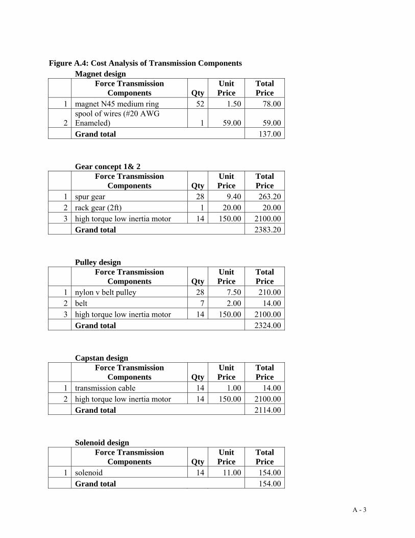
Figure A.4: Cost Analysis of Transmission Components Magnet design
Force Transmission
Components QtyUnit Price
Total Price
1 magnet N45 medium ring 52 1.50 78.00
2 spool of wires (#20 AWG Enameled) 1 59.00 59.00
Grand total 137.00 Gear concept 1& 2
Force Transmission
Components QtyUnit Price
Total Price
1 spur gear 28 9.40 263.202 rack gear (2ft) 1 20.00 20.003 high torque low inertia motor 14 150.00 2100.00
Grand total 2383.20 Pulley design
Force Transmission
Components QtyUnit Price
Total Price
1 nylon v belt pulley 28 7.50 210.002 belt 7 2.00 14.003 high torque low inertia motor 14 150.00 2100.00
Grand total 2324.00 Capstan design
Force Transmission
Components QtyUnit Price
Total Price
1 transmission cable 14 1.00 14.002 high torque low inertia motor 14 150.00 2100.00
Grand total 2114.00 Solenoid design
Force Transmission
Components QtyUnit Price
Total Price
1 solenoid 14 11.00 154.00 Grand total 154.00
A - 3
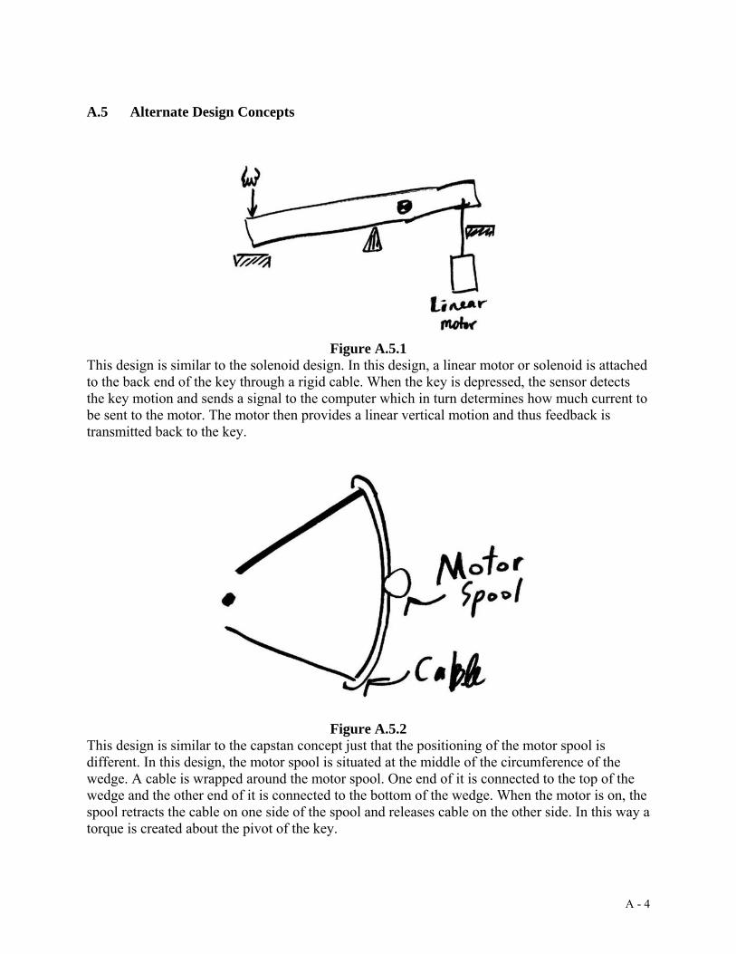
A.5 Alternate Design Concepts
Figure A.5.1
This design is similar to the solenoid design. In this design, a linear motor or solenoid is attached to the back end of the key through a rigid cable. When the key is depressed, the sensor detects the key motion and sends a signal to the computer which in turn determines how much current to be sent to the motor. The motor then provides a linear vertical motion and thus feedback is transmitted back to the key.
Figure A.5.2
This design is similar to the capstan concept just that the positioning of the motor spool is different. In this design, the motor spool is situated at the middle of the circumference of the wedge. A cable is wrapped around the motor spool. One end of it is connected to the top of the wedge and the other end of it is connected to the bottom of the wedge. When the motor is on, the spool retracts the cable on one side of the spool and releases cable on the other side. In this way a torque is created about the pivot of the key.
A - 4

Figure A.5.3
This design is again under the same family as the capstan design. This difference is in the location of the motor and the spool. Since a cable is used as the force transmission medium, the motor and spool could be placed in either a vertical or horizontal position because the cable could be twisted.
Figure A.5.4
In this design, the back of the key is attached to a bevel gear. This gear is going to mate with another bevel gear placed perpendicularly to the back of the key. When the motor is on, the force transmission will be such that the key is going to have a moment about its pivot. Using bevel gears might save some space because the motors could be placed parallel to the keys.
A - 5

Appendix A.6 DesignSafe 3.0 Report
A - 6

A - 7

A - 8

A - 9

A - 10

Figure A.7 Coil Mount Dimensions
A - 11

Table A.8: Bill of Materials Material Name Descriptions Estimated Cost
per unit Quantity Total
Cost General Purpose Materials
Aluminum 6061 6’x1”x1/8” bars $10.83 per bar 3 $32.49 3'x1"x1" bar $21.93 per bar 1 $21.93 1" cylindrical Free - from ME
x50 Labs per cylinder
24"x12"x1/4" plates $63.00 per plates 2 $126.00
Steel 1/4” cylindrical, 3' length
Free - from ME x50 Labs
per cylinder
3'x1/2"x2" bar $20.94 per bar 1 $20.94 Structural Casing
Plexiglass 8.5"x4"x1/2" Free - from ME x50 Labs
Alignment pins 12 Free - from Piano Technology Lab
Felt stops 12 Free - from Piano Technology Lab
Key Assembly Piano keys White and
black keys Free
Zinc-plated Steel Set Screw Shaft Collar
1/4” bore, 1/2” outside diameter, 9/32” width
$0.68
per collar 28 $19.04 Teflon bearings 1" cylindrical,
12" length $10.00
per rod 1 $10.00 Magnet Arrays
Brass 1/4" threaded rod, 12" length $7.00 per rod 4 $28.00
NB004 magnets 30 magnets, 2"x1"x½"
$3.92 per magnet 30 $117.60
Coil mounts Epoxy resin & catalyst
16 oz. container
$33.36 per container 1 $33.36
Wax block 4 pounds, 14” long, 3” wide, 3” deep
$13.77
per block 1 $13.77 Omegabond® 600 Chemical Set Cement
4 8 oz. containers
$46.00 per container 4 $184.00
A - 12

Machineable wax blocks
8 blocks 5"x3"x2"
Free - from ME x50 Labs 8
32 AWG Magnet wire
1 lb/spool Free - from Professor Gillespie's lab per spool 1
Electrical 8 terminal barrier strips
4 strips $1.50 per strip 4 $6.00
4 jack RCA plates
4 plates $1.00 per plate 4 $4.00
3 RCA cables 3 3' long stereo cables
$2.00 per cable 3 $6.00
22 AWG solid core wire
20 yards Free - from ME x50 Labs
Sensor Encoder Strip
0.007” thick, 0.7” wide
$14.70 for less than 7”, $2.10 more per inch above 7”
per inch
9 18.9 Sensors Free - from
team 2 per encoder
Various cables and connectors
Free - from Professor Gillespie's lab
Others Reamer 11/16" under-
sized chucking reamer
$34.00
per unit 1 $34.00 1/4" chucking
reamer $10.00
per unit 1 $10.00 Random fasteners and washers
$32.68 NEVER USED Rubber sheet 6”x6”x1/16” $9.77 per sheet 1 $9.77 Open Steel Ball Bearings
1/4” shaft, 11/16” outside diameter, 1/4” width
$3.71
per bearing 12 $44.52
Total Cost $773.00
A - 13

A.9 Final Design Engineering Drawings
Figure A.9.1 Key Arm Back
Figure A.9.2 Black Key Arm Front
A - 14

Figure A.9.3 Black Key Assembly
Figure A.9.4 Coil Assembly
A - 15

Figure A.9.5 Key Bed Top View
Figure A.9.6 Key Bed Side Views
A - 16

Figure A.9.7 Magnet Assembly
Figure A.9.8 Magnet Endcaps
A - 17

Figure A.9.10 Side Plates
Figure A.9.11 Side Plates
A - 18

Figure A.9.12 Side Plates
Figure A.9.13 Side Plates
A - 19

Figure A.9.14 Side Plates
Figure A.9.15 Magnet Spacers
A - 20

Figure A.9.16 White Key Front Arm
Figure A.9.17 White Key Assembly
A - 21

A.10 Wiring Schematics
Figure A.9 The IDC connector on the amplifier is the one that faces upwards if the
amplifier is resting on its four cylinders.
Figure A.10 The DB-15 connector faces perpendicular to the amplifier board surface.
A - 22

Figure A.11 The amplifier power supply is at the center of the amplifier board surface. If
the DB-15 connector is facing you, then this is an overhead view of the pinouts of the power supply connection.
Figure A.12 Sensor Engineering Drawing (scanned from US Digital)
A - 23

Figure A.13 cRIO-9263 Pinouts
The current LabView files make use of certain slots on the cRIO-9401 module. For sensor one, channel A goes to 14 and channel B goes to 16. For sensor 2, channel A goes to 20 and channel B goes to 22. For sensor 3, channel A goes to 23 and channel B goes to 25.
A - 24

A.11 LabView Screenshots Screenshots from the LabView file “Music Player.vi” which had coding for .wav file playback based on various position and velocity conditions.
Figure A.11.1 Music Player.vi Front Panel
Figure A.11.2 Music Player.vi Block Diagram 1
A - 25

Figure A.11.3 Music Player.vi Block Diagram 2 “Quadrature.vi” was the LabView file provided to us by Professor Gillespie. We modified the code to allow for multiple sensor inputs.
Figure A.11.4 Quadrature.vi Front Panel
A - 26
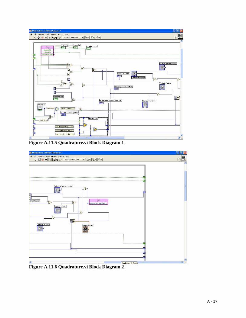
Figure A.11.5 Quadrature.vi Block Diagram 1
Figure A.11.6 Quadrature.vi Block Diagram 2
A - 27

Figure A.11.7 Quadrature.vi Block Diagram 3
A - 28

A.12 Prototype Pictures
Figure A.12.1 Team and prototype.
Figure A.12.2 Prototype assembly in pieces
A - 29

Figure A.12.3 Prototype assembly in pieces
Figure A.12.4 Keybed
A - 30

Figure A.12.5 Completed Prototype
A - 31