tristar energy solutionâ„¢ variable speed pump - hayward pools
TRANSCRIPT

P/N: IS3220VSC Rev: B
__________________________________________________________________________________________
OWNER’S MANUAL INSTALLATION, OPERATION, & PARTS
TriStar Energy SolutionTM Variable Speed Pump Control The Hayward TriStar Pump is specifically engineered for the demanding requirements of today’s in-ground swimming pool/spa that is equipped with large capacity filters, heaters, and pool cleaning equipment. The TriStar is a self-priming pump that includes an improved seal and impeller design that will provide many years of efficient, dependable, corrosion-free service. The advanced design provides superior performance while reducing maintenance requirements. NOTE - To prevent potential injury and to avoid unnecessary service calls, read this manual carefully and completely.
WARNING – The TriStar ES (Energy Solution) variable speed pump control is designed for use only with Hayward SP322063EEV 2.7 THP 3 phase pump. Do not use with any other pump models. Use of this control with any other pump model will void warranty. Refer to TriStar Owner’s Guide (IS3200) for all applicable pump installation, operation, and troubleshooting information.
SAVE THIS INSTRUCTION MANUAL
HAYWARD POOL PRODUCTS 620 DIVISION STREET ELIZABETH, NJ 07207 (908) 351-5400
WWW.HAYWARDPOOL.COM
TriStar Variable Speed Pump Control ____ ____________________________Page 2 of 16
WWW.HAYWARDPOOL.COM USE ONLY HAYWARD GENUINE REPLACEMENT PARTS
IMPORTANT SAFETY INSTRUCTIONS Before installing or servicing this electrical equipment, turn power supply OFF.
WARNING – Read and follow all instructions in this owner’s manual and on the equipment. Failure to follow instructions can cause severe injury and/or death.
WARNING – This product should be installed and serviced only by a qualified professional. CAUTION – All electrical wiring MUST be in conformance with all applicable local codes, regulations, and the
National Electric Code (NEC).
Use of non-Hayward replacement parts voids warranty.
ATTENTION INSTALLER – THIS MANUAL CONTAINS IMPORTANT INFORMATION ABOUT THE INSTALLATION, OPERATION, AND SAFE USE OF THIS PUMP THAT MUST BE FURNISHED TO THE END USER OF THIS PRODUCT. FAILURE TO READ AND FOLLOW ALL INSTRUCTIONS COULD RESULT IN SERIOUS INJURY.
WARNING – To reduce risk of injury, do not permit children to use or climb on this product. Closely supervise children at all times. Components such as the filtration system, pumps, and heaters must be positioned to prevent children from using them as a means of access to the pool.
CAUTION – This pump is intended for use on permanently installed swimming pools and may also be used with hot tubs and spas if so marked. Do NOT use with storable pools. A permanently installed pool is constructed in or on the ground or in a building such that it cannot be readily disassembled for storage. A storable pool is constructed so that it is capable of being readily disassembled for storage and reassembled to its original integrity. Though this product is designed for outdoor use, it is strongly advised to protect the electrical components from the weather. Select a well-drained area, one that will not flood when it rains. It requires free circulation of air for cooling. Do not install in a damp or non-ventilated location. If installed within an outer enclosure or beneath the skirt of a hot tub or spa, adequate ventilation and free circulation of air must be provided to prevent overheating of the motor.
WARNING – Pool and spa components have a finite life. All components should be inspected frequently and replaced at least every ten years, or if found to be damaged, broken, cracked, missing, or not securely attached.
Basic safety precautions should always be followed, including the following: Failure to follow instructions may result in injury.
This is the safety-alert symbol. When you see this symbol on your pump or in this manual, look for one of the following signal words and be alert to the potential for personal injury.
WARNING warns about hazards that could cause serious personal injury, death or major property damage and if ignored presents a potential hazard.
CAUTION warns about hazards that will or can cause minor or moderate personal injury and/or property damage and if ignored presents a potential hazard. It can also make consumers aware of actions that are unpredictable and unsafe. The NOTICE label indicates special instructions that are important but not related to hazards.
TriStar Variable Speed Pump Control ____ ____________________________Page 3 of 16
WWW.HAYWARDPOOL.COM USE ONLY HAYWARD GENUINE REPLACEMENT PARTS
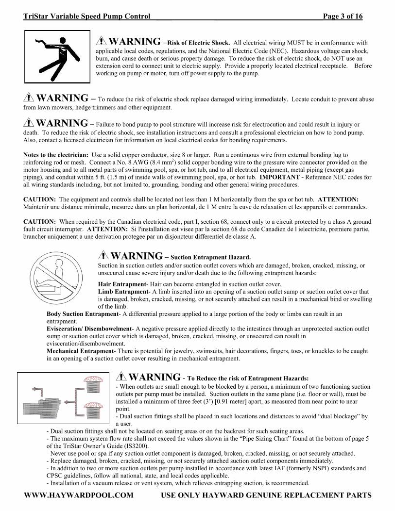
WARNING –Risk of Electric Shock. All electrical wiring MUST be in conformance with applicable local codes, regulations, and the National Electric Code (NEC). Hazardous voltage can shock, burn, and cause death or serious property damage. To reduce the risk of electric shock, do NOT use an extension cord to connect unit to electric supply. Provide a properly located electrical receptacle. Before working on pump or motor, turn off power supply to the pump.
WARNING – To reduce the risk of electric shock replace damaged wiring immediately. Locate conduit to prevent abuse from lawn mowers, hedge trimmers and other equipment.
WARNING – Failure to bond pump to pool structure will increase risk for electrocution and could result in injury or death. To reduce the risk of electric shock, see installation instructions and consult a professional electrician on how to bond pump. Also, contact a licensed electrician for information on local electrical codes for bonding requirements. Notes to the electrician: Use a solid copper conductor, size 8 or larger. Run a continuous wire from external bonding lug to reinforcing rod or mesh. Connect a No. 8 AWG (8.4 mm2) solid copper bonding wire to the pressure wire connector provided on the motor housing and to all metal parts of swimming pool, spa, or hot tub, and to all electrical equipment, metal piping (except gas piping), and conduit within 5 ft. (1.5 m) of inside walls of swimming pool, spa, or hot tub. IMPORTANT - Reference NEC codes for all wiring standards including, but not limited to, grounding, bonding and other general wiring procedures. CAUTION: The equipment and controls shall be located not less than 1 M horizontally from the spa or hot tub. ATTENTION: Maintenir une distance minimale, mesuree dans un plan horizontal, de 1 M entre la cuve de relaxation et les appareils et commandes. CAUTION: When required by the Canadian electrical code, part I, section 68, connect only to a circuit protected by a class A ground fault circuit interrupter. ATTENTION: Si l'installation est visee par la section 68 du code Canadien de l ielectricite, premiere partie, brancher uniquement a une derivation protegee par un disjoncteur differentiel de classe A.
WARNING – Suction Entrapment Hazard. Suction in suction outlets and/or suction outlet covers which are damaged, broken, cracked, missing, or unsecured cause severe injury and/or death due to the following entrapment hazards:
Hair Entrapment- Hair can become entangled in suction outlet cover. Limb Entrapment- A limb inserted into an opening of a suction outlet sump or suction outlet cover that is damaged, broken, cracked, missing, or not securely attached can result in a mechanical bind or swelling of the limb.
Body Suction Entrapment- A differential pressure applied to a large portion of the body or limbs can result in an entrapment. Evisceration/ Disembowelment- A negative pressure applied directly to the intestines through an unprotected suction outlet sump or suction outlet cover which is damaged, broken, cracked, missing, or unsecured can result in evisceration/disembowelment. Mechanical Entrapment- There is potential for jewelry, swimsuits, hair decorations, fingers, toes, or knuckles to be caught in an opening of a suction outlet cover resulting in mechanical entrapment.
WARNING - To Reduce the risk of Entrapment Hazards:
- When outlets are small enough to be blocked by a person, a minimum of two functioning suction outlets per pump must be installed. Suction outlets in the same plane (i.e. floor or wall), must be installed a minimum of three feet (3’) [0.91 meter] apart, as measured from near point to near point. - Dual suction fittings shall be placed in such locations and distances to avoid “dual blockage” by a user.
- Dual suction fittings shall not be located on seating areas or on the backrest for such seating areas. - The maximum system flow rate shall not exceed the values shown in the “Pipe Sizing Chart” found at the bottom of page 5 of the TriStar Owner’s Guide (IS3200). - Never use pool or spa if any suction outlet component is damaged, broken, cracked, missing, or not securely attached. - Replace damaged, broken, cracked, missing, or not securely attached suction outlet components immediately. - In addition to two or more suction outlets per pump installed in accordance with latest IAF (formerly NSPI) standards and CPSC guidelines, follow all national, state, and local codes applicable.
- Installation of a vacuum release or vent system, which relieves entrapping suction, is recommended.

TriStar Variable Speed Pump Control ____ ____________________________Page 4 of 16
WWW.HAYWARDPOOL.COM USE ONLY HAYWARD GENUINE REPLACEMENT PARTS
WARNING – Hazardous Pressure. Pool and spa water circulation systems operate under
hazardous pressure during start-up, normal operation, and after pump shut-off. Stand clear of circulation system equipment during pump start-up. Failure to follow safety and operation instructions could result in violent separation of the pump housing and cover due to pressure in the system, which could cause property damage, severe personal injury, or death. Before servicing pool and spa water circulation system, all system and pump controls must be in off position and filter manual air relief valve must be in open position. Before starting system pump, all system valves must be set in a position to allow system water to
return back to the pool. Do not change filter control valve position while system pump is running. Before starting system pump, fully open filter manual air relief valve. Do not close filter manual air relief valve until a steady stream of water (not air or air and water mix) is discharged from the valve. All suction and discharge valves MUST be OPEN when starting the circulation system. Failure to do so could result in severe personal injury and/or property damage.
WARNING – Separation Hazard. Failure to follow safety and operation instructions could
result in violent separation of pump components. Strainer cover must be properly secured to pump housing with strainer cover lock ring. Before servicing pool and spa circulation system, all system and pump controls must be in off position and filter manual air relief valve must be in open position. Do not operate pool and spa circulation system if a system component is not assembled properly, damaged, or missing. Do not operate pool and spa circulation system unless filter manual air relief valve body is in locked position in filter upper body. All suction and discharge valves MUST be OPEN when starting the circulation system.
Failure to do so could result in severe personal injury and/or property damage.
WARNING – Never operate or test the circulation system at more than 50 PSI maximum.
WARNING – Fire and burn hazard. Motors operate at high temperatures and if they are not properly isolated from any flammable structures or foreign debris they can cause fires, which may cause severe personal injury or death. It is also necessary to allow the motor to cool for at least 20 minutes prior to maintenance to minimize the risk for burns.
WARNING – Failure to install according to defined instructions may result in severe personal injury or death. General Information
Introduction
This manual contains information for the proper installation and operation of the Hayward TriStar Energy Solution Variable Speed Pump Control. The instructions in this manual MUST be followed precisely. Failure to install according to defined instructions will void warranty.
Control Features & Benefits
• 6 programmable speeds allow you to size the pump to your pool, maximize energy efficiency so you use just enough
electricity for each specific task, provide greater flexibility for spa and water features, and improve water circulation quality. • Extremely quiet operation, providing flexibility of placement for your equipment pad. • 24 hour programmable clock to customize each speed’s length of operation. • Wall mounted enclosure provides easy access. • 6 speed interface is easy to program and use, providing superior energy management by defaulting to a “Low Filter” speed to
filter your pools water. • Easy to use membrane touch-pad. • Illuminated digital display is easy to use at night. • Adapts to Goldline controls for remote operation. • Integrated memory recalls settings. • Comes complete with 9-1/2 ft. of cable and 8 ft. of conduit to connect to the pump. • Temperature and electrical loading protection.
TriStar Variable Speed Pump Control ____ ____________________________Page 5 of 16
WWW.HAYWARDPOOL.COM USE ONLY HAYWARD GENUINE REPLACEMENT PARTS
Installation & Wiring
ATTENTION – Refer to TriStar Owner’s Guide (IS3200) for all applicable pump installation, operation, and troubleshooting information.
Electrical
WARNING – All electrical wiring MUST conform to local codes, regulations, and the National Electric Code (NEC).
WARNING – Ground and bond control and motor before connecting to electrical power supply. Failure to ground and bond control and motor can cause serious or fatal electrical shock hazard. Do NOT ground to a gas supply line. To avoid dangerous or fatal electrical shock, turn OFF power to control and motor before working on electrical connections. Fire Hazard - match supply voltage to control and motor nameplate voltage. Insure that the electrical supply available agrees with the
control and motor’s voltage, phase, and cycle, and that the wire size is adequate for the HP (kW) rating and distance from the power source. Use copper conductors only. Line Power Supply Specs
Voltage: 230VAC, 60 Hz, Single Phase
Breaker: 20 amps Wire Size: 12 AWG
Use copper conductors only. For indoor/outdoor use. A disconnecting means located within sight of this control, and at least 5 ft. from the inside wall of the pool, spa, or hot tub, must be provided.
Voltage
Voltage at control and motor MUST NOT be more than 10% above or below motor name plate rated voltage, or components may overheat, causing overload tripping and reduced component life. If voltage is less than 90% or more than 110% of rated voltage when motor is running at full load, consult power company.
Grounding And Bonding
Install, ground, bond, and wire control and motor in accordance with local or national electrical code requirements. Permanently ground control and motor. Use green ground terminal provided under motor canopy or access place; use size and type wire required by code. Connect control and motor ground terminals to control enclosure ground. Bond control and motor to pool structure. Bonding will connect all metal parts within and around the pool with a continuous wire. Bonding reduces the risk of a current passing between bonded metal objects, which could potentially cause electrical shock if grounded or shorted. Reference NEC codes for all wiring standards including, but not limited to, grounding, bonding and general wiring procedures. Use a solid copper conductor, size 8 or larger. Run wire from external bonding lug to reinforcing rod or mesh. Connect a No. 8 AWG (8.4 mm2) solid copper bonding wire to the pressure wire connector provided on the control and motor housings and to all metal parts of swimming pool, spa, or hot tub, and to all electrical equipment, metal piping (except gas piping), and conduit within 5 ft. (1.5 m) of inside walls of swimming pool, spa, or hot tub.
Wiring
WARNING – All electrical wiring MUST conform to local codes, regulations, and the National Electric Code (NEC).
Control and pump MUST be permanently connected to circuit. If other lights or appliances are also on the same circuit, be sure to add their amp loads before calculating wire and circuit breaker sizes. Use the load circuit breaker as the Master On-Off switch. If the variable speed pump and control are being used to replace an existing pump that was controlled by a separate mechanical time clock, the control should be connected directly to the line power supply, bypassing the time clock. The time clock can then be used to power other equipment (such as a heater, heat pump, or booster pump) that requires the filter pump to be operating when used. If the time clock is used in this manner, it should be set to power the equipment during a time cycle when the variable speed pump is operating at an appropriate flow rate, as defined by the steps set in the sequencer menu.

TriStar Variable Speed Pump Control ____ ____________________________Page 6 of 16
WWW.HAYWARDPOOL.COM USE ONLY HAYWARD GENUINE REPLACEMENT PARTS
Installation Notes
1. TURN OFF THE ELECTRICAL POWER AT THE CIRCUIT BREAKER. 2. Find a location for the SP3220VSC on a vertical flat surface, out of the direct sunlight, which will not be flooded, and above
the pump. This location must be within 8 feet of the pump. Mount the control enclosure to this location using the provided attachment points. The control must be mounted such that the enclosure vents are free from obstructions and the door may be opened without issue. Do not mount the control enclosure inside a panel or tightly enclosed area, or directly to the side of a house.
3. Open door and remove panel containing control interface by removing two screws. Disconnect interface cable from Emerson SK drive, and place interface panel in a safe location away from water such that the interface does not make contact with anything.
4. Connect 230VAC line power supply wiring to terminal block and ground strip as shown. Spade terminals with up-turned lugs must be used to connect wiring to terminal block.
5. Connect included phase wiring from control to pump wiring marked #1-3 as shown in wiring diagram below. Connect green ground wire to motor ground screw.
6. Connect the control to the pool bonding system using 8AWG (6AWG for Canada) wire. A lug for bonding is provided on the outside/bottom of the enclosure.
7. After all electrical connections have been made, reconnect interface cable plug to Emerson SK drive, and replace interface panel using two screws.
8. Apply power to the system, and proceed to “Installer Initial Setup” on page 7.
Wiring Diagram

TriStar Variable Speed Pump Control ____ ____________________________Page 7 of 16
WWW.HAYWARDPOOL.COM USE ONLY HAYWARD GENUINE REPLACEMENT PARTS
Operation & Setup
VARIABLE SPEED INTERFACE – INSTALLER INITIAL SETUP1: Event Performed function Keypad active functions Display message Initial Power On. Or Initial Setup Override (pressing 4 during Power On).
System checks to determine if initial setup parameters were previously set. If not, system enters Select Language step of initial setup procedure.
Press Time Up/Dn button to select desired language. Press 6 (OK) to store current settings.
SELECT LANGUAGE *ENGLISH *ESPANOL *FRANCAIS
Language selection is complete.
Clock setup. Press 5 (Next) or 2 (Previous) buttons to select day of week, hours, and minutes settings. Press Time Up/Dn buttons to change the selected value (selected value will be displayed with underlining cursor). Press 6 (OK) to store current settings.
CHECK THE CLOCK *SET Mon 12:50pm
Clock setting is complete.
Prime Mode setup. Press Time Up/Dn buttons to select desired prime mode2 (prime mode should be selected based on height of pump inlet above water level in pool). Press 6 (OK) to store current settings.
PICK PRIME MODE *MORE THAN 5 FT *5 FEET OR LESS
Prime mode selection is complete.
Timer disabled: pump runs according to prime mode selected, and defaults to P2. Timer enabled: pump remains stopped until system time reaches Timer-On setting.
Use 1 – 6 buttons to switch pump to a preset mode. Use Time Up/Dn buttons to cause remaining time for current mode to increase/decrease by 5 minutes. Use % Flow Up/Dn buttons to change pump speed within predefined range.
*PRIME MODE* (when timer is disabled) *PUMP STOPPED* (when timer is enabled, until system time reaches Timer-On setting)
TriStar Variable Speed Pump Control ____ ____________________________Page 8 of 16
WWW.HAYWARDPOOL.COM USE ONLY HAYWARD GENUINE REPLACEMENT PARTS
VARIABLE SPEED INTERFACE – INITIAL SETUP NOTES:
1) When power is applied to the system for the first time, or if initial setup override is engaged, the user will have to set the system language, clock, and prime mode before the pump will operate. During the initial system setup, the 1 (Exit) button is not active. The user must make these selections before the system will allow the pump to operate. If a mistake is made during the initial setup, the user may override the incorrect setup by disconnecting power to the system, and re-applying power while pressing the 4 button. The language and clock settings may be changed after initial system setup as shown in the Installer Setup chart if needed. 2) The user must select the prime mode based on the layout of their pump installation. Choose “MORE THAN 5 FT” if the inlet of the pump is more than 5 feet above the water level in the pool, or choose “5 FEET OR LESS” if the inlet of the pump is 5 feet or less above the water level in the pool.

TriStar Variable Speed Pump Control ____ ____________________________Page 9 of 16
WWW.HAYWARDPOOL.COM USE ONLY HAYWARD GENUINE REPLACEMENT PARTS
VARIABLE SPEED INTERFACE – INSTALLER SETUP CHART Event Performed function Keypad active functions Display message Normal operation – any mode except prime
Operate according to active mode with % flow set for this mode and for preset time.
Press 3 and 4 simultaneously for more than 5 seconds to enter setup mode. The current active mode is continued without any change or interruption.
*SETUP–MAIN MENU
SETUP mode User keypad and display are in setup mode. The current active pump mode is continued without any change or interruption.
Press 1 (Exit) to exit setup. System will return to current active mode and current preset is displayed, for example “P2.LOW FILTER”.
P2. LOW FILTER (for example)
SETUP mode (continued)
(as above) Press 5 (Next) or 2 (Prev) to scroll through all available main menu options. See display for current menu option.
*LANGUAGE SETUP *CLOCK/TIMER
*PRIME HEIGHT *PRESET SETUP *SEQUENCER *RANGE SETUP *HARDWARE SETUP *CONTROL SETUP
SETUP mode (continued)
(as above) Press 6 (OK) to enter selected menu option, for example “LANGUAGE SETUP”. Press 1 (Exit) to exit the menu.
*LANGUAGE SETUP *ENGLISH
SETUP mode: LANGUAGE SETUP function
This feature allows setting desired language of displayed messages.
Press Time Up/Dn buttons to select desired language. Press 6 (OK) to store current settings.
*ENGLISH *ESPANIOL *FRENCH *ENGLISH SET!
SETUP mode: CLOCK/TIMER function
This menu allows the user to set the current day of week and time of day, as well as enable or disable the timer function, and define the timer “on” and “off” time.
To change day of week or time of day, confirm by pressing 6 (OK) button. An underlining cursor will appear below day-of-week value. Press 5 (Next) or 2 (Prev) to select either day-of-week, hours, or minutes with underlining cursor. Press Time Up/Dn buttons to change selected value. Pressing 6 (OK) causes system to store preset current time. Pressing 5 (Next) allows the user to enable or disable the Timer. Use Time Up/Dn buttons to select between Timer Enable or Timer Disable. Pressing 6 (OK) causes system to store this option.
*SET Sun 7:36pm (for example) *SET Sun 7:36pm *SET Sun 7:36pm *SET Sun 7:36pm *CLOCK SAVED! *TIMER ENABLED *TIMER DISABLED *TIMER SAVED!

TriStar Variable Speed Pump Control ____ ____________________________Page 10 of 16
WWW.HAYWARDPOOL.COM USE ONLY HAYWARD GENUINE REPLACEMENT PARTS
Press 5 (Next) to define the Timer-On time. To change these settings, confirm by pressing 6 (OK). An underlining cursor will appear below hours value. Press 5 (Next) or 2 (Prev) to select hours or minutes to be set, and use Time Up/Dn buttons to select desired value. Press 6 (OK) to store this option. Press 5 (Next) to define the Timer-Off time. This setting is changed the same as above.
*TMR.ON 8:00am *TMR.ON 8:00am *TMR.ON 8:00am *TIMER SAVED! *TMR.OFF 5:00pm
SETUP mode: PRIME HEIGHT function
This menu allows the user to view the prime mode that was selected during initial setup.
Press 6 (OK) to display the prime mode that was selected during initial setup. After initial setup, this becomes a read-only display.
*MORE THAN 5 FT (for example)
SETUP mode: PRESET SETUP function
This menu allows the user to define the pump speed and duration for each preset, which should be customized for each installation. Use 5 (Next) or 2 (Prev) to select preset to be setup.
For example, user stops on mode 4 (Medium High). Using % Flow Up/Dn buttons for currently displayed mode number causes desired pump speed to be set within predefined range. Using Time Up/Dn buttons for currently displayed mode number causes desired time to be set within predefined range. Press 6 (OK) to store preset time and % flow settings. Each preset is set the same as above.
*SELECT PRESET: 4 *P4.SPEED= 20% *P4.TIME= 1h 30m *P4.STORED!
SETUP mode: SEQUENCER function
This menu allows the user to define the active preset and duration for each sequence step, which should be customized for each installation. Use 5 (Next) or 2 (Prev) to select sequence step to be setup. Empty may be selected if the user does not need all of the sequence steps. Stop may be selected if the user wishes to stop the pump during peak energy periods or another time of day.
For example, user stops on sequence step 1 (S1). Use % Flow Up/Dn to select desired active preset for displayed sequence step, or to select Stop Mode or Empty. If Empty is selected, the sequence step will be skipped, and the next step will be active. When presets or Stop are selected for the sequence step, the step time defaults to the time set for the displayed preset. This step time may be changed using the Time Up/Dn buttons. Press 6 (OK) to store sequence step settings. Each sequence step is set the same as above.
*S1:P1 0h30min *S1:P3 1h45min *S1:STOP 3h30min *S1:EMPTY *S1.STORED!

TriStar Variable Speed Pump Control ____ ____________________________Page 11 of 16
WWW.HAYWARDPOOL.COM USE ONLY HAYWARD GENUINE REPLACEMENT PARTS
SETUP mode: RANGE SETUP function
This menu allows the user to define the range of pump speed that the % Flow Up/Dn buttons may temporarily change for each preset. Use 5 (Next) or 2 (Prev) to select preset range to be setup.
For example, user stops on preset 6 (Maximum Flow). Press % Flow Up/Dn buttons to display lowest possible flow for this preset. Press Time Up/Dn buttons to display highest possible flow for this preset. Press 6 (OK) to store this setting. Each preset range is set the same as above.
*SELECT PRESET: 6 *P6.L-SPEED= 15% *P6.H-SPEED= 100% *P6.STORED!

TriStar Variable Speed Pump Control ____ ____________________________Page 12 of 16
WWW.HAYWARDPOOL.COM USE ONLY HAYWARD GENUINE REPLACEMENT PARTS
POOL & SPA CONTROLLER – BASIC OPERATION3: Event Performed function Keypad active functions Display message Power Off RTC4 operation only.
All inactive >OFF<
Power On Configuration OK
Check configuration and proceed to Stop Mode.
System enters Stop Mode until RTC4 reaches Timer On time, or the user selects a preset on the keypad. All other functions are disabled.
HAYWARD POOL&SPA *VERSION 1.27* *PUMP STOPPED*
Stop Mode Pump is stopped until RTC4 reaches Timer On time, or the user selects a preset on the keypad.
Buttons 1-6 are active. When the user selects a preset on the keypad, the system enters Prime Mode. After priming, the system operates according to the preset that was selected.
*PRIME -> *P3 *PRIME -> *P1
Prime Mode Pump will prime first when a preset is selected during Stop Mode.
Pressing Time Up/Dn causes remaining time for Prime Mode to be displayed. Pressing 1-6 changes the preset which will be activated upon completion of Prime Mode. Pressing Flow Up/Dn displays pump speed. Pump speed cannot be changed during Prime Mode.
8 min REMAINS *PRIME -> *P4 PUMP SPEED 85%
End of prime Operate according to active mode with flow set for this mode and for preset time.
After Prime Mode is completed, the pump will operate according to the preset that was selected, and will re-enter Stop Mode when the preset expires.
P4. MEDIUM-HIGH (P4 indicates preset #4)
Timer activates the system. The system enters On-Period
System enters Prime Mode if the pump was stopped prior to On-Period, or system enters first sequence step if pump was running prior to On-Period.
*TIMER IS=ON* *PRIME MODE* S1 8:40am *P3 (S1 indicates sequence step #1; 8:40am is current time; *P3 is currently running preset defined in sequence step S1)
System operates during On-Period
System advances through sequence steps unil RTC4 reaches Timer-Off time. If sequence steps end before Timer-Off time is reached, system will default to P2 “Low Filter” speed.
% Flow and Time buttons as well as 1-6 buttons are active. The % Flow and Time buttons may be used to temporarily change the flow and time of the current sequence step. The 1-6 buttons may be used to temporarily override the current sequence step. The system will operate according to the selected preset and will advance to the next sequence step when the preset expires.
S1 8:40am *P4 (where *P4 is manually selected preset which overrides the current sequence step)

TriStar Variable Speed Pump Control ____ ____________________________Page 13 of 16
WWW.HAYWARDPOOL.COM USE ONLY HAYWARD GENUINE REPLACEMENT PARTS
Timer deactivates the system. The system enters Off-Period
Pump is stopped and system enters Stop Mode.
System enters Stop Mode as before.
*TIMER IS=OFF* *PUMP STOPPED*
VARIABLE SPEED INTERFACE - BASIC OPERATION NOTES:
3) Timer Enabled (recommended): When the timer is enabled, the pump will be stopped when the control first receives power, until the Timer-ON time is reached, at which time it will prime and proceed through the steps defined in the Sequencer menu. The pump will stop when the system reaches the Timer-OFF time. The pump may be manually stopped by pressing the 5 and 6 buttons simultaneously for more than 5 seconds. Pressing any preset button after manually stopping the pump will cause the pump to prime and operate according to the preset chosen. Timer Disabled: When the timer is disabled, the pump will prime when the control first receives power, and will then default to P2 (Low Filter). It will continue to run according to P2 until power is disconnected from the control. After the pump has primed, the % Flow and Time Up/Dn buttons, as well as the 1-6 buttons, are active. Pressing any of the 1-6 buttons will cause the pump to run temporarily according to the set flow and time for the chosen preset. The % Flow and Time Up/Dn buttons may be used to temporarily modify the set flow and time for the chosen preset. After the chosen preset expires, the pump will default back to P2. The pump may be manually stopped by pressing the 5 and 6 buttons simultaneously for more than 5 seconds. After the pump is stopped, it may be restarted by pressing the 5 and 6 buttons simultaneously again for more than 5 seconds, at which point the pump will prime and then default to P2 (Low Filter).
4) RTC – Real Time Clock 5) Factory defaults are as follows. User/installer may note custom presets in the spaces provided. 6) If the sequencer is used, user/installer may note custom sequencer settings in the spaces provided.
Sequence Step
Preset Used Duration Time Start
Timer On N/A N/A S1 S2 S3 S4 S5 S6 S7 S8
Timer Off N/A N/A
Factory Presets Custom Presets Mode Name % Flow Time % Flow Time
PRIME 5 FEET OR LESS MORE THAN 5 FEET
65 85
6 min 8 min
P1 Low 50 30 min P2 Low Filter 50 30 min P3 Medium Low 50 30 min P4 Medium High 50 30 min P5 High Filter Cleaner 50 30 min P6 Maximum Flow 50 30 min
TriStar Variable Speed Pump Control ____ ____________________________Page 14 of 16
WWW.HAYWARDPOOL.COM USE ONLY HAYWARD GENUINE REPLACEMENT PARTS
Troubleshooting
ATTENTION – Refer to TriStar Owner’s Guide (IS3200) for all applicable pump installation, operation, and troubleshooting information. Error Codes DEFAULTS LOADED! - indicates that system has been reset to factory defaults due to a bad configuration file stored in non-volatile memory. User settings will need to be reset. SEQUENCER INIT - indicates that sequencer settings have been cleared due to bad sequencer data file stored in non-volatile memory. Sequencer settings will need to be reset. E1:REF.SPEED df - indicates that control is not able to read maximum frequency value from the motor drive input power, which is used to calculate the actual % Flow. In such case, standard US value is used (60 Hz). E2:VFD Stopped - indicates that motor drive is stopped, and should be running according to selected user mode. When *MANUAL STOP* is selected, this message is not displayed. E3:VFD Fault! - indicates that motor drive is in fault (in trip). Fault conditions can be caused by motor overload (over temperature, over voltage, over current), or any other condition that causes motor drive to be inoperative such as motor stall or pump jam. In such case, the cause of motor fault should be corrected first, and then “manual stop” procedure should be performed to reset the drive and restore proper operation. E4:VFD Timeout! - indicates that communication between motor drive and the system is corrupted or there is no connection. In such case, power should be disconnected from controller, and RS485 connection cable should be observed and replaced if necessary. E5:UART CRC Err - indicates checksum errors during communication with motor drive. In such case, disconnect power from control, and ensure that all electrical wiring, connections, and terminals are properly attached and connected. E6:VFD EEPROM ER - indicates that internal Emerson EEPROM memory is corrupted. In such case, the Emerson drive will not hold its predefined configuration upon power failure. The control sets this configuration every time it is powered up, so normal operation is possible, but it is recommended to replace the Emerson drive. CLOCK IS NOT SET - indicates that the Real Time Clock in the control is not set or is invalid. In such case, the unit will not perform Timer or Sequencer functions until the RTC is set again by the user. This is an E7 error, however the “E7” part of the message is not shown due to its length. E8:Check SETUP! - indicates that default values for “% Flow” and “Time” for all modes were loaded as well as other parameters upon configuration/setup error. Such an error may occur when the system is powered up for the first time. In such case, operator should enter Setup menu (pressing and holding 3 and 4 buttons for more than 5 sec.) and check or modify all parameters. Exiting setup clears this error. If this error occurs every time the system is turned on (upon “power on”), it means that non-volatile memory (EEPROM) is corrupted and the interface should be replaced. E11:VFD OVERLOAD - indicates that Emerson drive is overloaded. This message is reported directly from the Emerson drive. Usually in such condition the drive either reduces the output current which results in the pump operating at a slower speed or trips and restarts. E12:MAINS LOSS! - indicates that Emerson drive has detected power loss on its internal power BUS. This message may also appear when mains power is lost and the unit is about to shut down automatically. E13:LOAD LIMIT! - indicates that Emerson drive has reached its load limit defined in LOAD MENU. This is an indication that the motor drive and the pump current configuration are working at its load limits. E14:EXT.CTRL ERR - indicates that the control has lost communication connection with external control unit (Goldline Aqua Logic). © Hayward Pool Products, 2007 All rights reserved.

TriStar Variable Speed Pump Control ____ ____________________________Page 15 of 16
WWW.HAYWARDPOOL.COM USE ONLY HAYWARD GENUINE REPLACEMENT PARTS
PRODUCT REGISTRATION (Retain For Your Records)
DATE OF INSTALLATION ____________________ INITIAL PRESSURE GAUGE READING (CLEAN FILTER) _______________________ PUMP MODEL SP322063EEV HORSEPOWER 2.0 FRHP (2.7 THP) FILTER MODEL ________________ SERIAL NUMBER _______________________

TriStar Variable Speed Pump Control ____ ____________________________Page 16 of 16
WWW.HAYWARDPOOL.COM USE ONLY HAYWARD GENUINE REPLACEMENT PARTS
▲Retain this Warranty Certificate (upper portion) in a safe and convenient location for your records. ▼DETACH HERE: Fill out bottom portion completely and mail within 10 days of purchase/installation, or register online.
HAYWARD® LIMITED WARRANTY
This control was inspected before shipment from our plant. To original purchasers of this control, Hayward Pool Products, 620 Division Street, Elizabeth, New Jersey, warrants its products to be free from defects in materials and workmanship for a period of ONE (1) year from the date of purchase. Parts which fail or become defective during the warranty period, except as a result of freezing, negligence, improper installation, use, or care, shall be repaired or replaced, at our option, without charge, within 90 days of the receipt of defective product, barring unforeseen delays. To obtain warranty replacements or repair, defective components or parts should be returned, transportation paid, to the place of purchase, or to the nearest authorized Hayward service center. For further Hayward dealer or service center information, contact Hayward customer service department. No returns may be made directly to the factory without the express written authorization of Hayward Pool Products, Inc. All other conditions and terms of the standard warranty apply. Hayward shall not be responsible for cartage, removal and/or reinstallation labor or any other such costs incurred in obtaining warranty replacements. The Hayward Pool Products warranty does not apply to components manufactured by others. For such products, the warranty established by the respective manufacturer will apply. Some states do not allow a limitation on how long an implied warranty lasts, or the exclusion or limitation of incidental or consequential damages, so the above limitation or exclusion may not apply to you. This warranty gives you specific legal rights, and you may also have other rights, which vary from state to state. This product is intended for use only with SP322063EEV pump. Use with any other pump will void warranty. Hayward Pool Products 620 Division Street *Supersedes all previous publications. Elizabeth, NJ 07207