triple eccentric metal seated butterfly · pdf filea-t armaturen ltd. schroedahl & arapp...
TRANSCRIPT
A-T ARMATUREN LTD.
SCHROEDAHL & ARAPPMade in Germany
Triple EccentricMetal Seated
Butterfly Valves
Triple EccentricMetal Seated
Butterfly Valves
TABLE OF CONTENTS PAGE No.
A-T ARMATUREN LTD.
http://www.schroedahl.com
http://www.a-tcontrols.com
Manufacturing profile 1
Triple off-set theory 2
Seal and Seat combination 3
Cast Steel 4
Stainless Steel 5
6
Dimensions 150#, 300#, 600# 7
Gear Operartor 8
Dimensions and Weights
Valve Design:
Face to Face
Dimension:
End Flange
Dimensions:
Butt Weld Ends:
Test:
Fire Test:
Certificates:
API 6D
API 6A
ISO 9001
API 6FA, API 607
API 6D, ASME B16.34,
ASME B 31.3
ASME B16.10
ASME B16.5, ASME B16.47
MSS SP 44
ASME B 16.25
API 6D, API 598
API 6FA, API 607
Standard
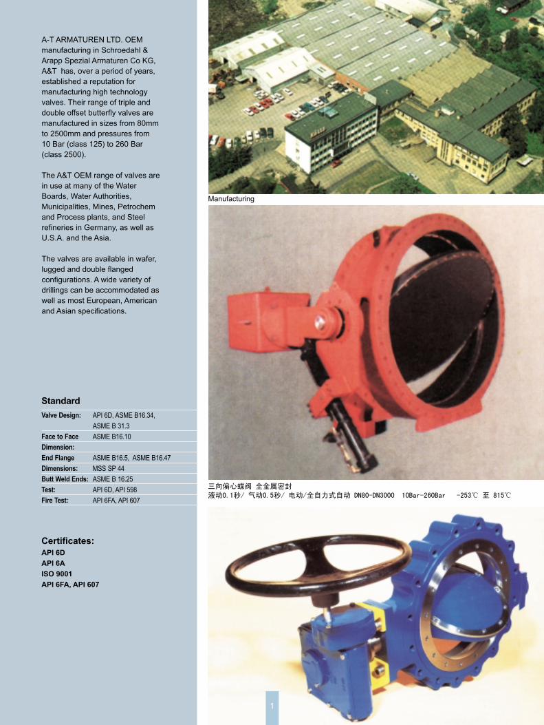
Manufacturing
1
A-T ARMATUREN LTD. OEM
manufacturing in Schroedahl &
Arapp Spezial Armaturen Co KG,
A&T has, over a period of years,
established a reputation for
manufacturing high technology
valves. Their range of triple and
double offset butterfly valves are
manufactured in sizes from 80mm
to 2500mm and pressures from
10 Bar (class 125) to 260 Bar
(class 2500).
The A&T OEM range of valves are
in use at many of the Water
Boards, Water Authorities,
Municipalities, Mines, Petrochem
and Process plants, and Steel
refineries in Germany, as well as
U.S.A. and the Asia.
The valves are available in wafer,
lugged and double flanged
configurations. A wide variety of
drillings can be accommodated as
well as most European, American
and Asian specifications.
A-T ARMATUREN LTD.
THE TRIPLE OFF-SET DESIGN PRINCIPLE
2
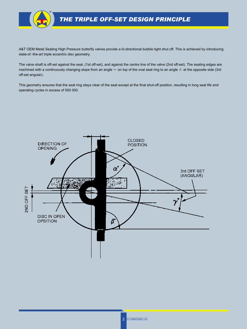
A&T OEM Metal Seating High Pressure butterfly valves provide a bi-directional bubble tight shut off. This is achieved by introducing
state-of -the-art triple eccentric disc geometry.
The valve shaft is off-set against the seal, (1st off-set), and against the centre line of the valve (2nd off-set). The seating edges are
machined with a continuously changing slope from an angle on top of the oval seat ring to an angle at the opposite side (3rd
off-set angular).
This geometry ensures that the seat ring stays clear of the seat except at the final shut-off position, resulting in long seat life and
operating cycles in excess of 500 000.
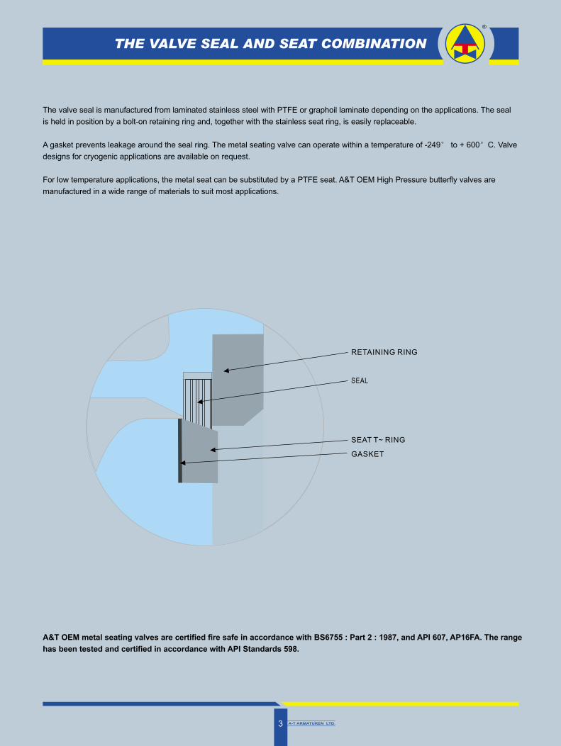
THE VALVE SEAL AND SEAT COMBINATION
A-T ARMATUREN LTD.3
The valve seal is manufactured from laminated stainless steel with PTFE or graphoil laminate depending on the applications. The seal
is held in position by a bolt-on retaining ring and, together with the stainless seat ring, is easily replaceable.
A gasket prevents leakage around the seal ring. The metal seating valve can operate within a temperature of -249 to + 600 C. Valve
designs for cryogenic applications are available on request.
For low temperature applications, the metal seat can be substituted by a PTFE seat. A&T OEM High Pressure butterfly valves are
manufactured in a wide range of materials to suit most applications.
RETAINING RING
SEAL
SEAT T~ RING
GASKET
A&T OEM metal seating valves are certified fire safe in accordance with BS6755 : Part 2 : 1987, and API 607, AP16FA. The range
has been tested and certified in accordance with API Standards 598.
A-T ARMATUREN LTD.4
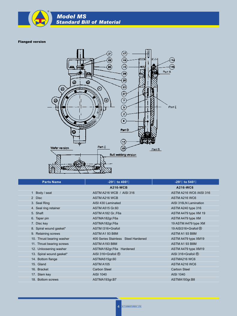
Model MSStandard Bill of Material
Flanged version
Parts Name -29 to 400 -29 to 540
1 Body / seat
2 Disc
3. Seal Ring
4. Seal ring retainer
5. Shaft
6. Taper pin
7. Disc key
8. Spiral wound gasket*
9. Retaining screws
10. Thrust bearing washer
11. Thrust bearing screws
12. Unloosening washer
13. Spiral wound gasket*
14. Bottom flange
15. Gland
16. Bracket
17. Stem key
18. Bottom screws
ASTM A216 WCB / AISI 316
ASTM A216 WCB
AISI 430 Laminated
ASTM A515 Gr.60
ASTM A182 Gr..F6a
ASTMA182gr.F6a
ASTMA182gr.F6a
ASTM I316+Grafoil
ASTM A1 93 B8M
400 Series Stainless Steel Hardened
ASTM A193 B8M
ASTMA182gr.F6a Hardened
AISI 316+Grafoil
ASTMA515gr.60
ASTM A105
Carbon Steel
AISI 1040
ASTMA193gr.B7
R
ASTM A216 WC6 /AISI 316
ASTM A216 WC6
AISI 316LN Lamination
ASTM A240 type 316
ASTM A479 type XM 19
ASTM A479 type XM
19 ASTM A479 type XM
19 AISI316+Grafoil
ASTM A1 93 B8M
ASTM A479 type XM19
ASTM A1 93 B8M
ASTM A479 type XM19
AISI 316+Grafoil
ASTMA216 WC6
ASTM A216 WC6
Carbon Steel
AISI 1040
ASTMA193gr.B8
R
R
A216-WCB A216-WC6
A-T ARMATUREN LTD.5
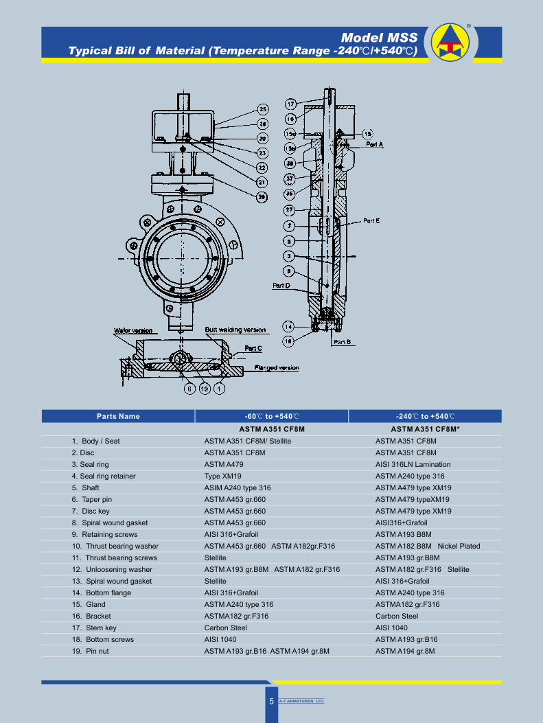
Model MSSTypical Bill of Material (Temperature Range -240 /+540 )
Parts Name
1. Body / Seat
2. Disc
3. Seal ring
4. Seal ring retainer
5. Shaft
6. Taper pin
7. Disc key
8. Spiral wound gasket
9. Retaining screws
10. Thrust bearing washer
11. Thrust bearing screws
12. Unloosening washer
13. Spiral wound gasket
14. Bottom flange
15. Gland
16. Bracket
17. Stem key
18. Bottom screws
19. Pin nut
ASTM A351 CF8M/ Stellite
ASTM A351 CF8M
ASTM A479
Type XM19
ASIM A240 type 316
ASTM A453 gr.660
ASTM A453 gr.660
ASTM A453 gr.660
AISI 316+Grafoil
ASTM A453 gr.660 ASTM A182gr.F316
Stellite
ASTM A193 gr.B8M ASTM A182 gr.F316
Stellite
AISI 316+Grafoil
ASTM A240 type 316
ASTMA182 gr.F316
Carbon Steel
AISI 1040
ASTM A193 gr.B16 ASTM A194 gr.8M
ASTM A351 CF8M
ASTM A351 CF8M
AISI 316LN Lamination
ASTM A240 type 316
ASTM A479 type XM19
ASTM A479 typeXM19
ASTM A479 type XM19
AISI316+Grafoil
ASTM A193 B8M
ASTM A182 B8M Nickel Plated
ASTM A193 gr.B8M
ASTM A182 gr.F316 Stellite
AISI 316+Grafoil
ASTM A240 type 316
ASTMA182 gr.F316
Carbon Steel
AISI 1040
ASTM A193 gr.B16
ASTM A194 gr.8M
-60 to +540 -240 to +540
ASTM A351 CF8M ASTM A351 CF8M*
A-T ARMATUREN LTD.6
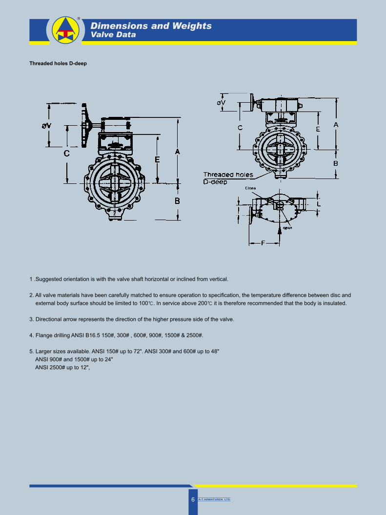
Dimensions and WeightsValve Data
Threaded holes D-deep
1 .Suggested orientation is with the valve shaft horizontal or inclined from vertical.
2. All valve materials have been carefully matched to ensure operation to specification, the temperature difference between disc and
external body surface should be limited to 100 . In service above 200 it is therefore recommended that the body is insulated.
3. Directional arrow represents the direction of the higher pressure side of the valve.
4. Flange drilling ANSI B16.5 150#, 300# , 600#, 900#, 1500# & 2500#.
5. Larger sizes available. ANSI 150# up to 72". ANSI 300# and 600# up to 48"
ANSI 900# and 1500# up to 24"
ANSI 2500# up to 12",
A-T ARMATUREN LTD.7
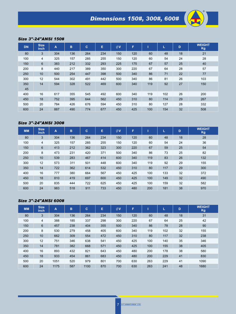
Size 3"-24"ANSI 150#
3
4
6
8
10
12
14
16
18
20
24
304
325
383
440
500
544
594
617
752
784
887
136
157
212
217
254
302
328
355
395
426
490
264
285
332
389
447
491
522
545
644
676
774
234
255
293
350
398
442
469
492
562
594
677
150
150
225
300
500
500
600
600
450
450
450
120
120
175
220
340
340
340
340
310
310
425
60
60
67
67
86
86
119
119
80
80
100
48
54
57
64
71
81
92
102
114
127
154
18
24
25
28
22
26
27
26
29
28
32
21
28
40
57
77
103
150
200
267
332
508
80
100
150
200
250
300
350
45
400
450
500
600
Sizeinch
DN A B C E V F I L DWEIGHT
Kg
Size 3"-24"ANSI 300#
3
4
6
8
10
12
14
16
18
20
24
304
325
413
473
539
573
722
777
810
835
983
136
157
212
231
283
311
362
380
419
444
518
264
285
362
420
467
501
614
664
697
722
911
234
255
323
371
414
448
532
567
600
625
733
150
150
300
500
600
600
450
450
450
450
450
120
120
220
340
340
340
310
425
425
425
480
60
60
67
86
119
119
80
100
100
100
200
48
54
59
73
83
92
117
133
149
159
181
18
24
25
25
26
29
29
32
32
32
38
28
36
54
82
132
155
300
372
490
582
970
80
100
150
200
250
300
350
400
450
500
600
Sizeinch
MM A B C E V F I L DWEIGHT
Kg
Size 3"-24"ANSI 600#
3
4
6
8
10
12
14
16
18
20
24
304
388
457
530
662
751
781
893
933
1051
1175
136
185
238
279
309
346
382
432
454
520
587
264
337
404
458
554
638
668
821
861
979
1100
234
298
355
405
472
541
571
643
683
801
870
150
300
500
600
450
450
450
450
450
700
700
120
220
340
340
310
425
425
480
480
630
630
60
67
86
119
80
100
100
200
200
263
263
48
64
78
102
117
140
155
178
229
229
241
18
25
28
32
32
35
38
38
41
41
48
31
42
90
155
238
346
405
580
830
1090
1680
80
100
150
200
250
300
350
400
450
500
600
Sizeinch
MM A B C E V F I L DWEIGHT
Kg
Dimensions 150#, 300#, 600#
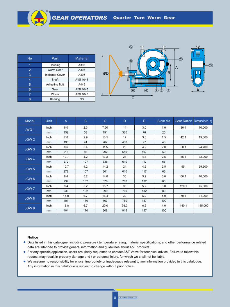
GEAR OPERATORS Quarter Turn Worm Gear
Model Unit
Inch
mm
Inch
mm
Inch
mm
Inch
mm
Inch
mm
Inch
mm
Inch
mm
Inch
mm
Inch
mm
D E Torque(inch.lb)
Notice
Data listed in this catalogue, including pressure / temperature rating, material specifications, and other performance related
data are intended to provide general information and guidelines about A&T products.
For any specific application, users are kindly requested to contact A&T Valve for technical advice. Failure to follow this
request may result in property damage and / or personal injury, for which we shall not be liable.
We assume no responsibility for errors, impropriety or inadequacy relevant to any information provided in this catalogue.
Any information in this catalogue is subject to change without prior notice.
JWG 1
JGW 2
JGW 3
JGW 4
JGW 5
JGW 6
JGW 7
JGW 8
JGW 9
A B C Stem dia Gear Ration
6.0
152
7.6
193
8.6
218
10.7
272
10.7
272
9.4
239
9.4
238
15.8
401
15.8
404
2.3
58
2.9
74
3.4
86
4.2
107
4.2
107
5.2
132
5.2
132
6.7
170
6.7
170
7.50
191
10.5
267
11.5
292
13.2
335
14.2
361
14.8
376
15.7
399
18.4
467
20.0
508
14
360
17
430
20
510
24
610
24
610
30
760
30
760
30
760
36.0
915
3.0
76
3.8
97
4.2
107
4.6
117
4.6
117
5.2
132
5.2
132
6.2
157
6.2
157
1.0
25
1.5
40
2.0
50
2.5
65
2.5
65
3.0
80
3.0
80
4.0
100
4.0
100
30:1
42:1
50:1
55:1
55:
60:1
120:1
70:1
140:1
10,000
19,800
24,700
32,000
59,500
40,000
75,000
81,000
155,000
No Part
Housing
Worm Gear
Indicator Cover
Shaft
Adjusting Bolt
Gear
Worm
Bearing
1
2
3
4
5
6
7
8
Material
A395
A395
A395
AISI 1045
A449
AISI 1045
AISI 1045
CS
A
C
D
18746
8
5
2
B
E
3
A-T ARMATUREN LTD.8
A T SERVOVALVE ENGINEERING-
20010 Ossona , Italy.
Fax: +39-02-90296708
Trunnion Ball Valve Factory
A-T CONTROLS CORPORATION
Cincinnati, Ohio, USA.
www.a-tcontrols.com
Fax: 1-513-247-5462
Floating Ball Valve Factory
A & T ARMATUREN
67433 Neustadt / Weinstr,
Siegfriedstr 15, Germany.
Fax: +49-6321-34657
Control & Instrumenation
Room 1206 Chevalier House, 45-51 Chatham Road South,
TsimShaTsui, HongKong.
http://www.a-tcontrols.com
http://www.schroedahl.com
Logistic distribution Centre
E-mail:[email protected]
: 45-51 1206
: 6 618
: 111 4F
Tel: 852-25073069 Fax: 852-25074599
Tel: 010-63101382 Fax: 010-63103936
Tel: 020-87373329 Fax: 020-87383699
A-T ARMATUREN LTD.
http://www.schroedahl.comhttp://www.a-tcontrols.com
Germany manufacturer of A-T
Armaturen Ltd wholly owned subsidary
under K. Wah International Ltd.
http://www.schroedahl.com
fax:+49-9131-6907140