trinica and trinica select anterior cervical · the trinica® and trinica® select anterior...
TRANSCRIPT
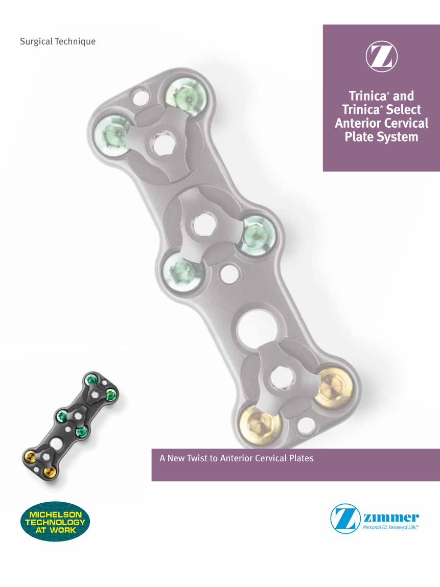
Trinica® andTrinica® Select
Anterior CervicalPlate System
A New Twist to Anterior Cervical Plates
Surgical Technique

1Trinica and Trinica Select Surgical Technique
Trinica® and Trinica® Select Anterior Cervical Plate System
TABLE OF CONTENTSIndications and Preparation 2
Plate Selection, Bending and Initial Placement
Plate Selection 3 Plate Bending (Optional) 4 Temporary Fixation Pins 4
Screw Selection
Self-Tapping vs. Self-Drilling 5 Alternative Screws 6
Bone Screw Hole Preparation
Fixed Screw Placement (Drill Guide) 6 Alternative: Fixed Screw Placement (Awl) 8 Variable Screw Placement (Drill Guide) 8
Bone Screw Insertion
Screw Insertion 10
System Locking
Securing the Locking Caps 11
All-Through-One Guide Tube
Single Barrel 13 Double Barrel 21
2 Trinica and Trinica Select Surgical Technique
PATIENT INDICATIONS
AND PREPARATION
Indications
The Trinica® and Trinica® Select Anterior Cervical Plate System was designed for anterior interbody screw fixation of the cervical spine at levels C2-T1. The system is indicated for use in the temporary stabilization of the anterior spine during the development of cervical spinal fusions in patients with degenerative disc disease (as defined by neck pain of discogenic origin confirmed by patient history and radiographic studies), trauma (including fractures), tumors, deformity (defined as kyphosis, lordosis, or scoliosis), pseudoarthrosis and/or failed previous fusions.
Warning: This device is not approved for screw attachment to the posterior
elements (pedicles) of the cervical, thoracic, or lumbar spine.
Patient Positioning and Preparation
Prepare the patient for an anterior cervical fusion using the standard surgical technique.

3Trinica and Trinica Select Surgical Technique
Plate Selection
Overview: Select the appropriately-sized plate for fixation to the vertebral bodies. A properly-sized plate will bridge the affected segment(s) without overhanging into adjacent disc space.
Plate Holder: A Plate Holder is included in the Trinica instrument set to facilitate plate selection and initial placement. It may be used to stabilize the plate during insertion of the Temporary Fixation Pins or initial Bone Screws.
To use the Plate Holder, snap the tip into any of the bone screw holes. Rotate the Plate as necessary to achieve proper orientation. Place the plate into position over the affected disc space and press down on the top cap of the Plate Holder to extend the bone pick.
To release the Plate Holder, retract the bone pick by pulling back on the top cap and tilt the Plate Holder toward the midline or center of the plate to free the tip from the plate.
Figure 2
4 Trinica and Trinica Select Surgical Technique
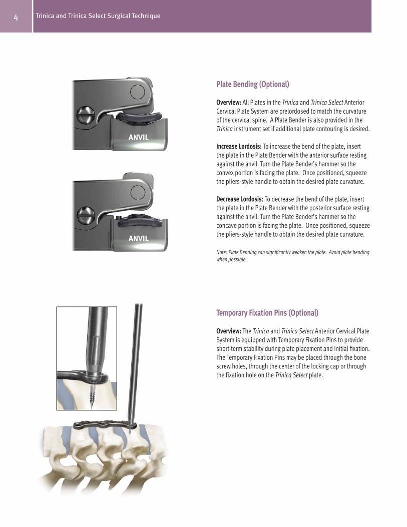
Plate Bending (Optional)
Overview: All Plates in the Trinica and Trinica Select Anterior Cervical Plate System are prelordosed to match the curvature of the cervical spine. A Plate Bender is also provided in the Trinica instrument set if additional plate contouring is desired.
Increase Lordosis: To increase the bend of the plate, insert the plate in the Plate Bender with the anterior surface resting against the anvil. Turn the Plate Bender’s hammer so the convex portion is facing the plate. Once positioned, squeeze the pliers-style handle to obtain the desired plate curvature.
Decrease Lordosis: To decrease the bend of the plate, insert the plate in the Plate Bender with the posterior surface resting against the anvil. Turn the Plate Bender’s hammer so the concave portion is facing the plate. Once positioned, squeeze the pliers-style handle to obtain the desired plate curvature.
Note: Plate Bending can significantly weaken the plate. Avoid plate bending when possible.
Temporary Fixation Pins (Optional)
Overview: The Trinica and Trinica Select Anterior Cervical Plate System is equipped with Temporary Fixation Pins to provide short-term stability during plate placement and initial fixation. The Temporary Fixation Pins may be placed through the bone screw holes, through the center of the locking cap or through the fixation hole on the Trinica Select plate.
ANVIL
ANVIL

5Trinica and Trinica Select Surgical Technique
Temporary Fixation Pins
Pin Insertion: To use the Temporary Fixation Pins, insert a pin into the Pin Inserter and place it in the desired plate hole. Rotate the Pin Inserter clockwise to advance the pin into the vertebra.
Pin Removal: To remove the Temporary Fixation Pins, use the Pin Inserter/Remover to engage the top portion of the pin and rotate counterclockwise to remove the pin.
Note: The Temporary Fixation Pins are intended for single use only and should be discarded after one use.
Note: Temporary Fixation Pins must be removed from the surgical site prior to closure.
Screw Selection – Self-Tapping vs. Self-Drilling
The Trinica and Trinica Select self-drilling screws seek to give the surgeon the option to reduce the number of instruments used in a Trinica Anterior Cervical Plate surgery. Reducing the amount of instruments has the potential to reduce the amount of retraction and time to implant a cervical plate.
The difference between the self-drilling and self-tapping screws is in the tip of the screw. The cutting flute design on the self-drilling screws eliminates the need for a drill or awl to penetrate the cortex of the vertebral body.
Fixed, self-drilling screws may be identified by a gold anodized head and variable self-drilling screws may be identified by a green anodized head. The self-tapping screws are completely anodized.
Note: The trajectory of the screws must be considered when using the freehand approach to placing self-drilling screws. It is recommended that the appropriate All-Through-One Guide Tube (variable or fixed angle) be used when placing self-drilling screws. If the angle of the screw trajectory is too great, it may not be possible to fully seat the screw within the plate and will cause difficulty when closing the Trinica locking mechanism.
Pin RemovalPin Insertion
Self-DrillingCutting Flute
Self-TappingBlunt Tip
6 Trinica and Trinica Select Surgical Technique
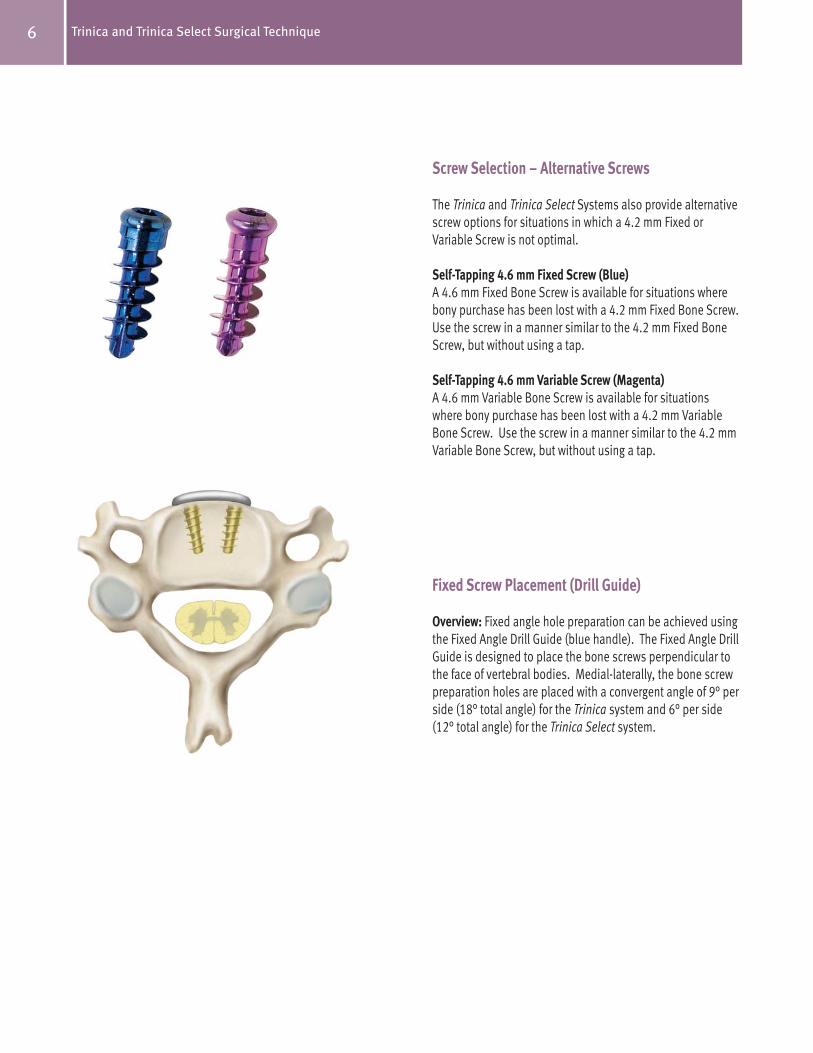
Screw Selection – Alternative Screws
The Trinica and Trinica Select Systems also provide alternative screw options for situations in which a 4.2 mm Fixed or Variable Screw is not optimal.
Self-Tapping 4.6 mm Fixed Screw (Blue)
A 4.6 mm Fixed Bone Screw is available for situations where bony purchase has been lost with a 4.2 mm Fixed Bone Screw. Use the screw in a manner similar to the 4.2 mm Fixed Bone Screw, but without using a tap.
Self-Tapping 4.6 mm Variable Screw (Magenta)
A 4.6 mm Variable Bone Screw is available for situations where bony purchase has been lost with a 4.2 mm Variable Bone Screw. Use the screw in a manner similar to the 4.2 mm Variable Bone Screw, but without using a tap.
Fixed Screw Placement (Drill Guide)
Overview: Fixed angle hole preparation can be achieved using the Fixed Angle Drill Guide (blue handle). The Fixed Angle Drill Guide is designed to place the bone screws perpendicular to the face of vertebral bodies. Medial-laterally, the bone screw preparation holes are placed with a convergent angle of 9° per side (18° total angle) for the Trinica system and 6° per side (12° total angle) for the Trinica Select system.

7Trinica and Trinica Select Surgical Technique
Fixed Screw Placement (Drill Guide) Continued
Placement/Hole Preparation: To prepare a bone screw insertion hole using the Fixed Angle Drill Guide, insert the tip of the Drill Guide into the desired screw pocket in the plate. Once positioned, insert the standard Drill into the Drill Guide and advance the Drill by rotating clockwise until the positive stop on the Drill contacts the Fixed Angle Drill Guide. When complete, remove the Drill from the Drill Guide.
Note: The Drill is intended for single patient use only and should be discarded after use.
Tapping (Optional): A Tap is provided in the Trinica instrument set to create threads in bone. To use the Tap, position the Drill Guide over the previously drilled hole. Insert the Tap into the Drill Guide and advance by rotating clockwise until the positive stop contacts the Fixed Angle Drill Guide. Once contact is obtained, rotate the Tap counterclockwise until it is free of the bone and remove it from the Drill Guide.
Caution: Do not continue to rotate the Tap once the positive stop contacts
the top of the Drill Guide. Continued rotation of the Tap may strip the bone
threads.
After the bone screw hole has been prepared, remove the Fixed Angle Drill Guide and place the bone screw as outlined. Repeat the bone screw preparation placement procedure for all remaining screw sites.

8 Trinica and Trinica Select Surgical Technique
(Alternative): Fixed Screw Placement (Awl)
Overview: As an alternative to the use of the Fixed Angle Drill Guide, Drill and Tap, a Fixed Angle Awl is included in the Trinica instrument set.
Placement/Hole Preparation: To use the Awl, place the tip into the desired screw pocket in the Plate. Once inserted, twist the handle back and forth while applying downward pressure to the handle. Continue advancing the tip of the Awl until reaching the positive stop.
Remove the Fixed Angle Awl from the bone screw pocket and place the bone screw as directed. Repeat the bone screw preparation and placement procedure outlined above for all remaining bone screw preparation sites.
Variable Screw Placement (Drill Guide)
Overview: A Variable Angle Guide (green handle) is included in the Trinica instrument set. The Variable Angle Guide is designed to allow varied placement of the bone screws. This guide allows for screw placement at a conical angle of +/- 12° (superior/inferior) from the fixed reference point.

9Trinica and Trinica Select Surgical Technique
Variable Screw Placement (Drill Guide) Continued
Placement/Hole Preparation: To use the Variable Angle Drill Guide, insert the tip of the Drill Guide into the screw pocket and position the Guide at the desired angle. Once positioned, insert the standard Drill into the Drill Guide. Advance the Drill by rotating clockwise until the positive stop on the Drill contacts the Variable Angle Drill Guide. When complete, remove the Drill from the Drill Guide.
Note: The Drill is intended for single patient use only and should be discarded after use.
Tapping (Optional): A Tap is provided in the Trinica instrument set to create threads in bone. To use the Tap, position the Drill Guide over the previously drilled hole. Insert the Tap into the Drill Guide and advance using a clockwise rotation until the positive stop comes into contact with the Variable Angle Drill Guide. Once contact is obtained, rotate the Tap counterclockwise until it is free of the bone and remove it from the Drill Guide.
Caution: Do not continue to rotate the Tap once the positive stop contacts
the top of the Drill Guide. Continued rotation of the Tap may strip the bone
threads.
After the bone screw hole has been prepared, remove the Variable Angle Drill Guide and place the bone screw as directed. Repeat the bone screw preparation and placement procedure outlined above for all remaining bone screw preparation sites.

10 Trinica and Trinica Select Surgical Technique
Screw Insertion
Insertion: Select the desired screw type and length. Insert the tip of the Hex Driver into the socket of the bone screw using downward pressure on the driver to secure the screw to the driver tip. Insert the screw in the desired bone site and rotate the Hex Driver clockwise to advance the screw until it is firmly seated.
Caution: Do not continue to advance the bone screw once the screw is
firmly seated in the Plate. Continued screw tightening may strip the bone
threads.
11Trinica and Trinica Select Surgical Technique
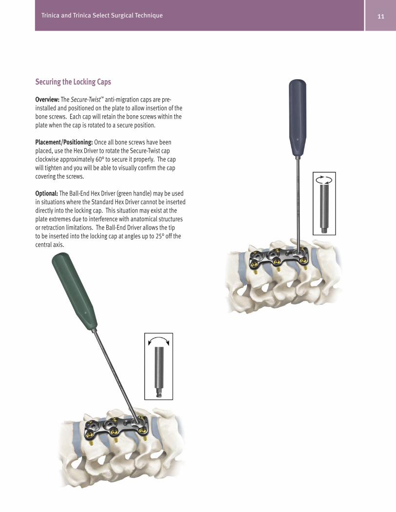
Securing the Locking Caps
Overview: The Secure-Twist™ anti-migration caps are pre-installed and positioned on the plate to allow insertion of the bone screws. Each cap will retain the bone screws within the plate when the cap is rotated to a secure position.
Placement/Positioning: Once all bone screws have been placed, use the Hex Driver to rotate the Secure-Twist cap clockwise approximately 60° to secure it properly. The cap will tighten and you will be able to visually confirm the cap covering the screws.
Optional: The Ball-End Hex Driver (green handle) may be used in situations where the Standard Hex Driver cannot be inserted directly into the locking cap. This situation may exist at the plate extremes due to interference with anatomical structures or retraction limitations. The Ball-End Driver allows the tip to be inserted into the locking cap at angles up to 25° off the central axis.

12 Trinica and Trinica Select Surgical Technique
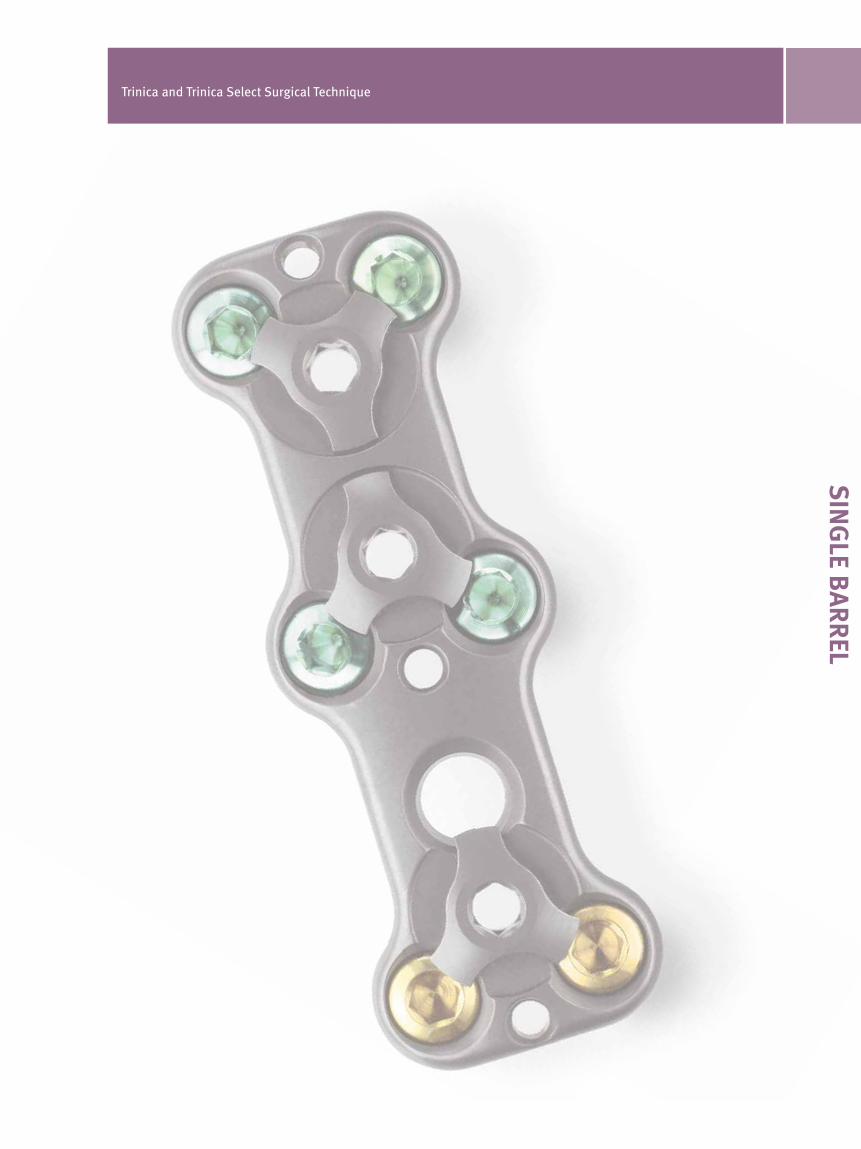
SIN
GLE B
AR
REL
Trinica and Trinica Select Surgical Technique
13Trinica and Trinica Select Surgical Technique
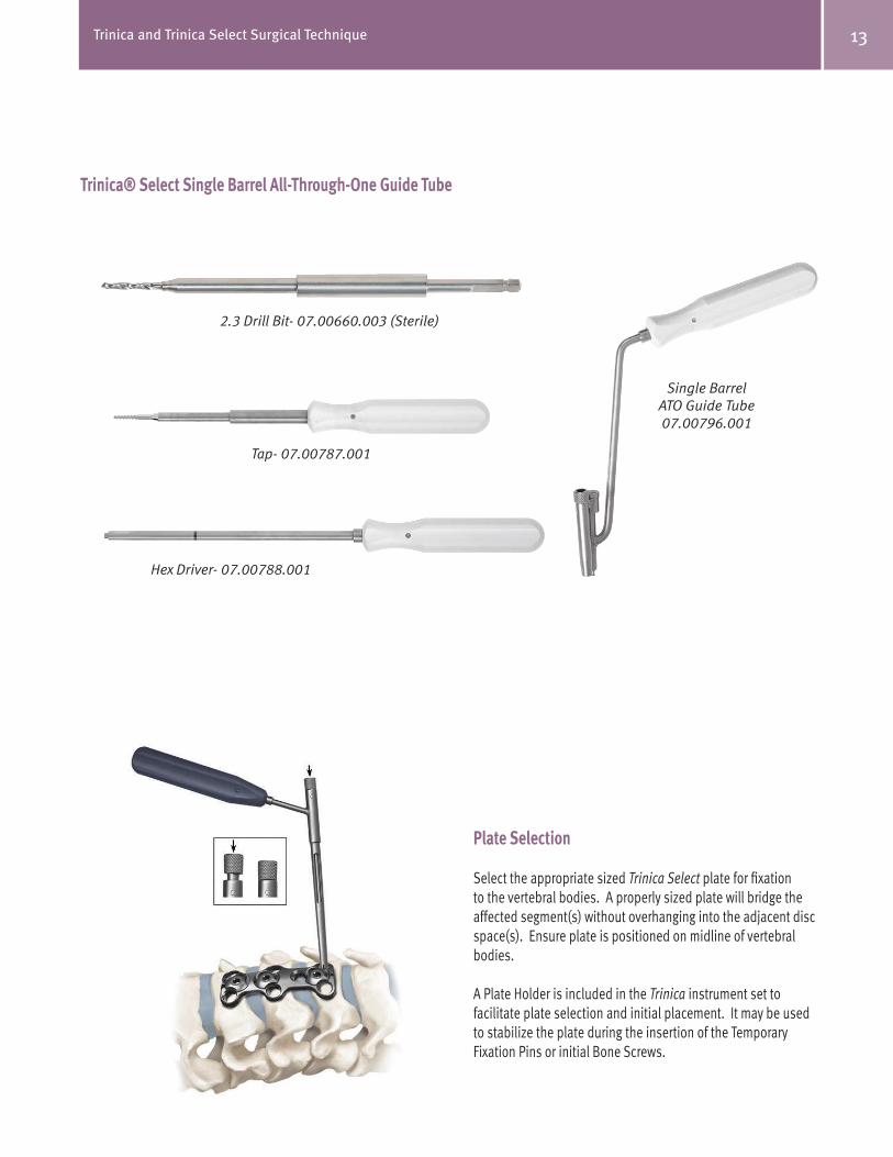
Trinica® Select Single Barrel All-Through-One Guide Tube
2.3 Drill Bit- 07.00660.003 (Sterile)
Tap- 07.00787.001
Hex Driver- 07.00788.001
Single BarrelATO Guide Tube07.00796.001
Plate Selection
Select the appropriate sized Trinica Select plate for fixation to the vertebral bodies. A properly sized plate will bridge the affected segment(s) without overhanging into the adjacent disc space(s). Ensure plate is positioned on midline of vertebral bodies.
A Plate Holder is included in the Trinica instrument set to facilitate plate selection and initial placement. It may be used to stabilize the plate during the insertion of the Temporary Fixation Pins or initial Bone Screws.
14 Trinica and Trinica Select Surgical Technique
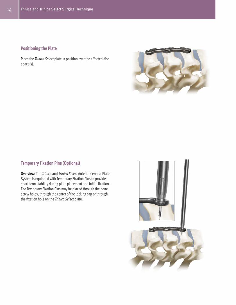
Positioning the Plate
Place the Trinica Select plate in position over the affected disc space(s).
Temporary Fixation Pins (Optional)
Overview: The Trinica and Trinica Select Anterior Cervical Plate System is equipped with Temporary Fixation Pins to provide short-term stability during plate placement and initial fixation. The Temporary Fixation Pins may be placed through the bone screw holes, through the center of the locking cap or through the fixation hole on the Trinica Select plate.
15Trinica and Trinica Select Surgical Technique
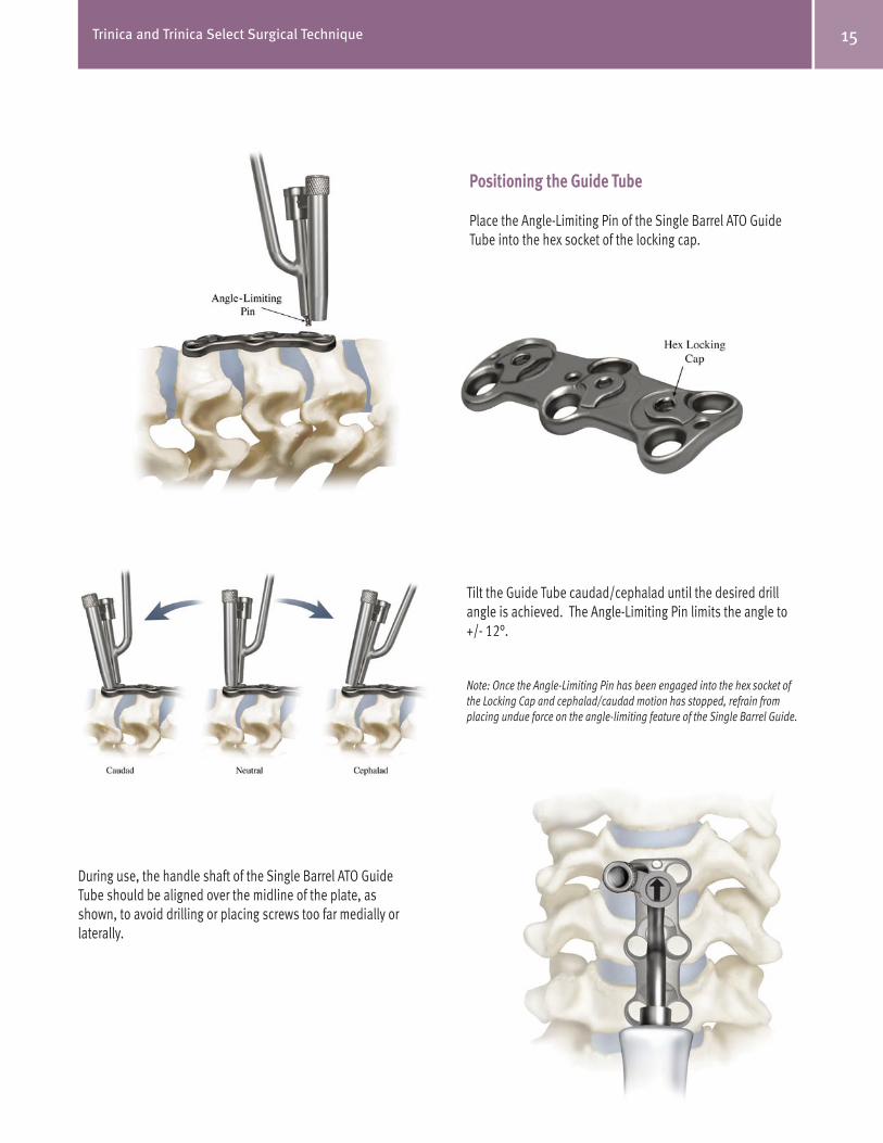
Tilt the Guide Tube caudad/cephalad until the desired drill angle is achieved. The Angle-Limiting Pin limits the angle to +/- 12°.
Note: Once the Angle-Limiting Pin has been engaged into the hex socket of the Locking Cap and cephalad/caudad motion has stopped, refrain from placing undue force on the angle-limiting feature of the Single Barrel Guide.
During use, the handle shaft of the Single Barrel ATO Guide Tube should be aligned over the midline of the plate, as shown, to avoid drilling or placing screws too far medially or laterally.
Positioning the Guide Tube
Place the Angle-Limiting Pin of the Single Barrel ATO Guide Tube into the hex socket of the locking cap.

16 Trinica and Trinica Select Surgical Technique
Hole Placement/Preparation
Attach ONLY the ATO Drill Bit (Part# 07.00660.003) to either the manual drill handle (supplied in the Trinica Instrument Set) or a compatible device with an AO connector. Only use the ATO Drill Bit with the Single Barrel ATO Guide Tube. Insert ATO Drill Bit into the ATO Guide Tube and with minor downward pressure, advance the ATO Drill Bit by rotating clockwise until the positive stop on the ATO Drill Bit contacts the ATO Guide Tube. Continue to rotate the ATO Drill Bit clockwise as you remove the ATO Drill Bit from the ATO Guide Tube.

17Trinica and Trinica Select Surgical Technique
Screw Placement
Identify the appropriate style screw, Self-Drilling or Self-Tapping (see pages 5-6). Once a screw style has beendetermined, identify the correct screw type, Fixed or Variable,and the length. Insert the tip of the ATO Hex Driver into thesocket of the screw using downward pressure on the driver tosecure the screw to the driver tip.
With the screw attached to the ATO Hex Driver, position theATO Hex Driver in the Guide Tube. Insert the screw tip into thepreviously drilled and/or tapped hole. Rotate the ATO HexDriver clockwise to advance the screw until it is firmly seated.Final adjustments may be needed once the Guide Tube has been removed.
Note: The ATO Hex Driver has a Visual Indicator incorporated on the shaft. When the Visual Indicator reaches the top of the Guide Tube, the screw is nearly seated.
Caution: Do not continue to advance the bone screw once the screw is firmly
seated in the Plate. Continued screw tightening may strip the bone threads.
Tapping (Optional)
To use the ATO Tap (Part #07.00787.001), position the Tap inthe Guide Tube and into the previously drilled hole. Advancethe ATO Tap rotating clockwise until the positive stop contactsthe Guide Tube. Once contact is made, rotate the Tapcounterclockwise until it is free of the bone and remove it fromthe Guide Tube.
Caution: Do not continue to rotate the Tap once the positive stop contacts
the top of the Drill Guide. Continued rotation of the Tap may strip the bone
threads.
18 Trinica and Trinica Select Surgical Technique
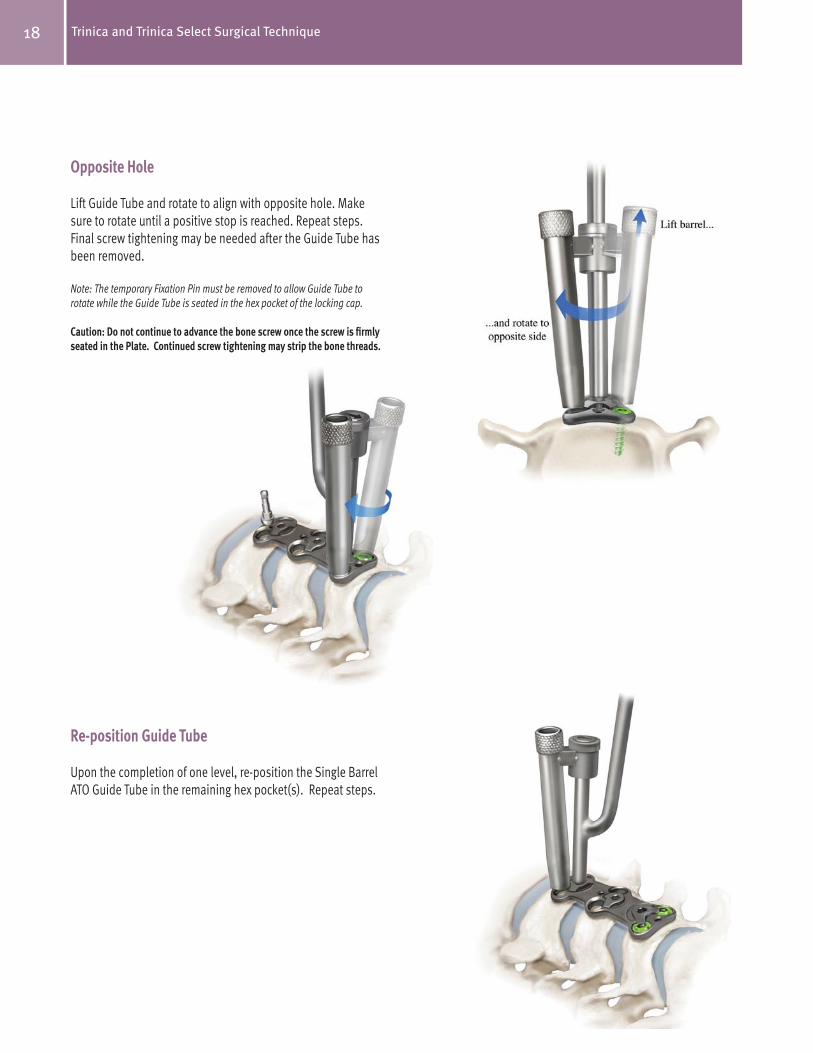
Opposite Hole
Lift Guide Tube and rotate to align with opposite hole. Makesure to rotate until a positive stop is reached. Repeat steps.Final screw tightening may be needed after the Guide Tube hasbeen removed.
Note: The temporary Fixation Pin must be removed to allow Guide Tube to rotate while the Guide Tube is seated in the hex pocket of the locking cap.
Caution: Do not continue to advance the bone screw once the screw is firmly
seated in the Plate. Continued screw tightening may strip the bone threads.
Re-position Guide Tube
Upon the completion of one level, re-position the Single Barrel ATO Guide Tube in the remaining hex pocket(s). Repeat steps.

Securing the Locking Caps
Overview: The Secure-Twist™ anti-migration caps are pre-installed and positioned on the plate to allow insertion of the bone screws. Each cap will retain the bone screws within the plate when the cap is rotated to a secure position.
Placement/Positioning: Once all bone screws have been placed, use the Hex Driver to rotate the Secure-Twist cap clockwise approximately 60° to secure it properly. The cap will tighten and you will be able to confirm visually that the cap is covering the screws.
Optional: The Ball-End Hex Driver (green handle) may be used in situations where the Standard Hex Driver cannot be inserted directly into the locking cap. This situation may exist at the plate extremes due to interference with anatomical structures or retraction limitations. The Ball-End Driver allows the tip to be inserted into the locking cap at angles up to 25° off the central axis.
19Trinica and Trinica Select Surgical Technique

20 Trinica and Trinica Select Surgical Technique

DO
UB
LE BA
RR
EL
Trinica and Trinica Select Surgical Technique
21Trinica and Trinica Select Surgical Technique
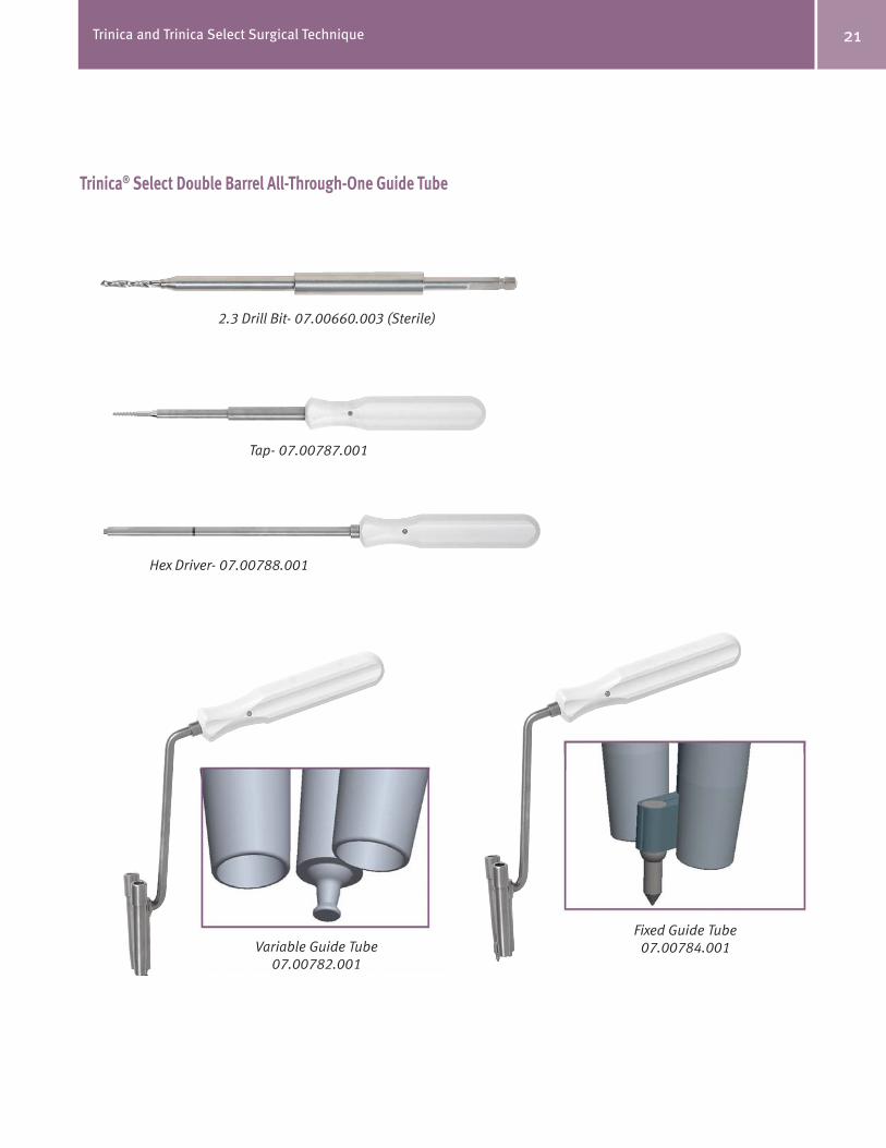
Trinica® Select Double Barrel All-Through-One Guide Tube
Variable Guide Tube07.00782.001
Fixed Guide Tube07.00784.001
2.3 Drill Bit- 07.00660.003 (Sterile)
Tap- 07.00787.001
Hex Driver- 07.00788.001
Fixed ATO Double Barrel
Guide Tube
Variable ATO Double Barrel
Guide Tube
22 Trinica and Trinica Select Surgical Technique
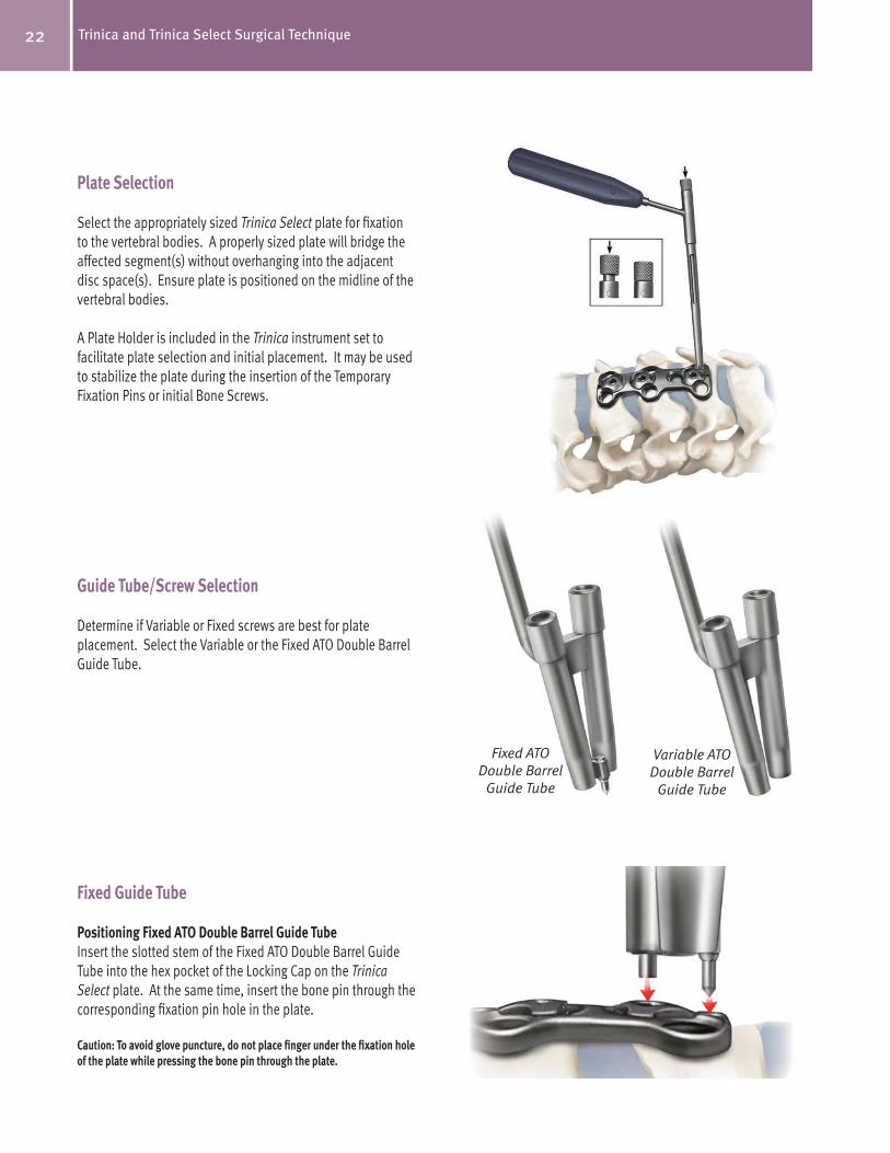
Plate Selection
Select the appropriately sized Trinica Select plate for fixation to the vertebral bodies. A properly sized plate will bridge the affected segment(s) without overhanging into the adjacent disc space(s). Ensure plate is positioned on the midline of the vertebral bodies.
A Plate Holder is included in the Trinica instrument set to facilitate plate selection and initial placement. It may be used to stabilize the plate during the insertion of the Temporary Fixation Pins or initial Bone Screws.
Guide Tube/Screw Selection
Determine if Variable or Fixed screws are best for plate placement. Select the Variable or the Fixed ATO Double Barrel Guide Tube.
Fixed Guide Tube
Positioning Fixed ATO Double Barrel Guide Tube
Insert the slotted stem of the Fixed ATO Double Barrel Guide Tube into the hex pocket of the Locking Cap on the Trinica Select plate. At the same time, insert the bone pin through the corresponding fixation pin hole in the plate.
Caution: To avoid glove puncture, do not place finger under the fixation hole
of the plate while pressing the bone pin through the plate.
23Trinica and Trinica Select Surgical Technique
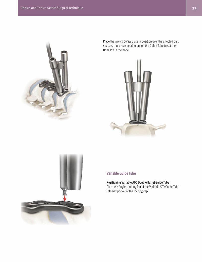
Place the Trinica Select plate in position over the affected disc space(s). You may need to tap on the Guide Tube to set theBone Pin in the bone.
Variable Guide Tube
Positioning Variable ATO Double Barrel Guide Tube
Place the Angle-Limiting Pin of the Variable ATO Guide Tube into hex pocket of the locking cap.

24 Trinica and Trinica Select Surgical Technique
Note: The handle shaft of the Guide Tube should be aligned over the midline of the plate, as shown right, to avoid drilling or placing screws too far medially or laterally.
Reposition the Guide Tube until the desired screw placement angle is achieved.
Note: Once the Angle-Limiting Pin is engaged and travel has stopped, refrain from placing undue force on the Angle-Limiting Pin of the Variable Guide Tube.
25Trinica and Trinica Select Surgical Technique
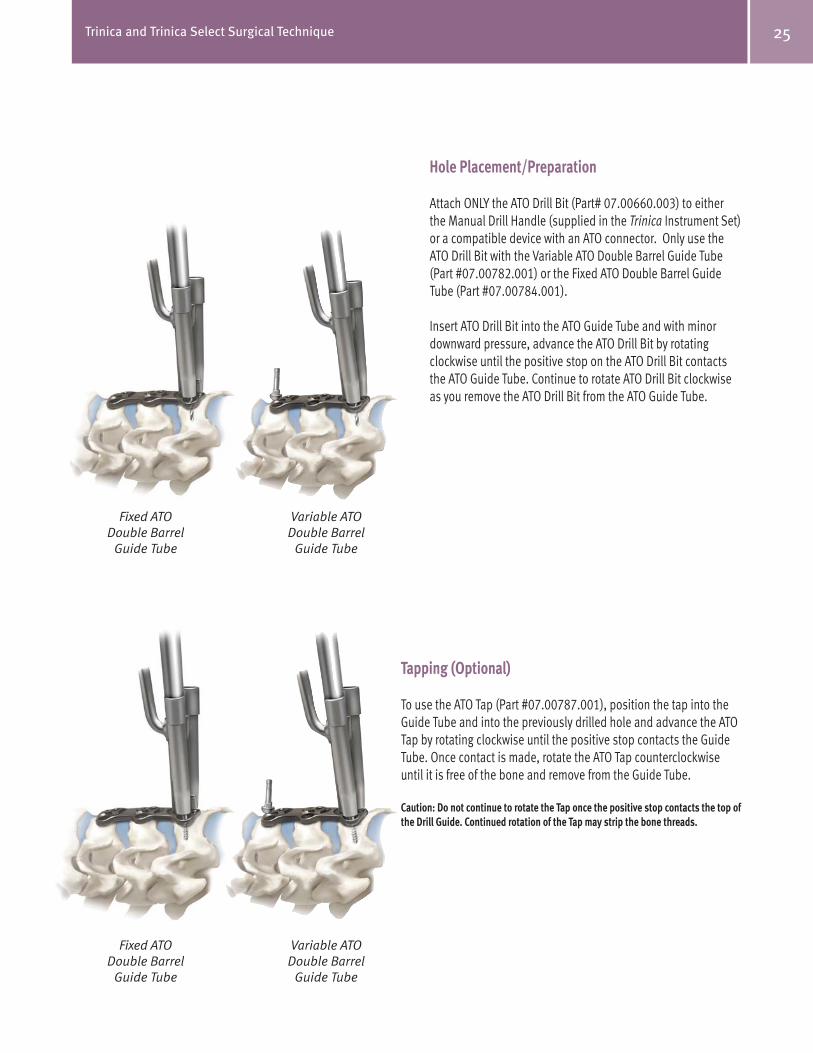
Hole Placement/Preparation
Attach ONLY the ATO Drill Bit (Part# 07.00660.003) to either the Manual Drill Handle (supplied in the Trinica Instrument Set) or a compatible device with an ATO connector. Only use the ATO Drill Bit with the Variable ATO Double Barrel Guide Tube (Part #07.00782.001) or the Fixed ATO Double Barrel Guide Tube (Part #07.00784.001).
Insert ATO Drill Bit into the ATO Guide Tube and with minor downward pressure, advance the ATO Drill Bit by rotating clockwise until the positive stop on the ATO Drill Bit contacts the ATO Guide Tube. Continue to rotate ATO Drill Bit clockwise as you remove the ATO Drill Bit from the ATO Guide Tube.
Tapping (Optional)
To use the ATO Tap (Part #07.00787.001), position the tap into the Guide Tube and into the previously drilled hole and advance the ATO Tap by rotating clockwise until the positive stop contacts the Guide Tube. Once contact is made, rotate the ATO Tap counterclockwise until it is free of the bone and remove from the Guide Tube.
Caution: Do not continue to rotate the Tap once the positive stop contacts the top of
the Drill Guide. Continued rotation of the Tap may strip the bone threads.
Fixed ATO Double Barrel
Guide Tube
Variable ATO Double Barrel
Guide Tube
Fixed ATO Double Barrel
Guide Tube
Variable ATO Double Barrel
Guide Tube

26 Trinica and Trinica Select Surgical Technique
Screw Placement
Identify the appropriate style screw, Self-Drilling or Self-Tapping (see pages 5-6). Once a screw style has been determined, identify the correct screw type (Fixed or Variable) and length. Insert the tip of the ATO Hex Driver into the socket of the screw using downward pressure on the driver to secure the screw to the driver tip.
With the screw attached to the ATO Hex Driver, position the ATO Hex Driver in the Guide Tube. Insert the screw tip in the previously drilled and/or tapped hole. Rotate the ATO Hex Driver clockwise to advance the screw until it is firmly seated. Repeat process for the second screw. Final adjustments may be needed once the Guide Tube has been removed.
Note: The ATO Hex Driver has a Visual Indicator incorporated on the shaft. When the Visual Indicator reaches the top of the Guide Tube, the screw is nearly seated.
Caution: Do not continue to advance the bone screw once the screw
is firmly seated in the Plate. Continued screw tightening may
strip the bone threads.
Re-Position Guide Tube
Repeat steps.
Variable ATO Double Barrel
Guide Tube
Fixed ATO Double Barrel
Guide Tube

27Trinica and Trinica Select Surgical Technique
Securing the Locking Caps
Overview: The Secure-Twist™ anti-migration caps are pre-installed and positioned on the plate to allow insertion of the bone screws. Each cap will retain the bone screws within the plate when the cap is rotated to a secure position.
Placement/Positioning: Once all bone screws have been placed, use the Hex Driver to rotate the Secure-Twist cap clockwise approximately 60° to secure it properly. The cap will tighten and you will be able to visually confirm that the cap is covering the screws.
Optional: The Ball-End Hex Driver (green handle) may be used in situations where the Standard Hex Driver cannot be inserted directly into the locking cap. This situation may exist at the plate extremes due to interference with anatomical structures or retraction limitations. The Ball-End Driver allows the tip to be inserted into the locking cap at angles up to 25° off the central axis.
28 Trinica and Trinica Select Surgical Technique
DEVICE DESCRIPTIONThe Trinica® and Trinica® Select Anterior Cervical Plate Systems consist of cervical plates, locking caps, bone screws, and the instruments necessary to implant this specific system. All implant components are made from a titanium alloy (Ti-6Al-4V). The Trinica and Trinica Select Anterior Cervical Plate Systems are intended to provide stabilization of the cervical vertebra for various indications (see below). The fixation construct consists of a cervical plate that is attached to the vertebral body of the cervical spine with self-tapping and self-drilling bone screws using an anterior approach. Bone screws are available for fixed angle or variable angle implantation. The Trinica and Trinica Select Anterior Cervical Plate Systems are intended to be removed after solid fusion has occurred.
INDICATIONSThe Trinica and Trinica Select Anterior Cervical Plate Systems are intended for anterior interbody screw fixation of the cervical spine. The Systems are indicated for use in the temporary stabilization of the anterior spine during the development of cervical spinal fusions in patients with degenerative disc disease (as defined by neck pain of discogenic origin with degeneration of the disc confirmed by patient history and radiographic studies), trauma (including fractures), tumors, deformity (defined as kyphosis, lordosis, or scoliosis), pseudoarthrosis, and/or failed previous fusions.
WARNING: These devices are not approved for screw attachment to the posterior elements (pedicles) of the cervical, thoracic, or lumbar spine.
CONTRAINDICATIONSContraindications for use of the Trinica and Trinica Select Anterior Cervical Plate Systems include:
WARNINGSSome metals, polymers, chemicals, and other materials utilized with orthopedic implants have been known to cause cancer and other adverse body reactions, or reports in the literature have suggested such causation. Any factor that causes chronic damage to tissues may be oncogenic. Cancer can metastasize from soft tissue sites (lung, breast, digestive system, and others) to bone, including areas adjacent to implants, or it can be seeded to these locations during operative and diagnostic procedures (such as biopsies). Paget’s disease has been reported to progress to cancer; surgical candidates suffering from this disease should be warned accordingly.
Implantation of foreign material in tissues can elicit an inflammatory reaction. Current literature suggests that wear debris (including metal, polyethylene, ceramic, and cement particles) can initiate the process of histiocytic granuloma formation and consequent osteolysis and loosening.
Metal sensitivity has been reported following exposure to orthopedic implants. The most common metallic sensitivities (nickel, cobalt, and chromium) are present in medical grade stainless steel and cobalt-chrome alloys.
Trinica and Trinica Select Anterior Cervical Plate Systems are temporary internal fixation devices. Internal fixation devices are designed to stabilize the operative site during the normal healing process. After healing occurs, these devices serve no functional purpose and must be removed. Implant removal, should be followed by adequate postoperative management to avoid fracture or refracture.
PRECAUTIONSThe Trinica and Trinica Select Anterior Cervical Plate Systems instrumentation should only be used after the surgeon has had adequate training in this method of fixation and has become thoroughly knowledgeable about the spinal anatomy and biomechanics. A surgical technique for the Trinica and Trinica Select Anterior Cervical Plate Systems is available upon request. This technique is not a substitute for training and is for general informational purposes only.
Components from other anterior cervical plating systems must not be intermixed with the Trinica and Trinica Select Anterior Cervical Plate Systems components since compatibility of the components is not known.
Do not use implants made from dissimilar metals (such as cobalt chromium-molybdenum alloy or stainless steel) in contact with components of the Trinica and Trinica Select Anterior Cervical Plate Systems; otherwise, galvanic corrosion may occur.
If contouring of the implant is necessary for optimal fit, the contouring should be gradual and avoid any notching or scratching of the implant(s) surface. The plates must not be repeatedly or excessively bent. Do not reverse-bend the plate.
All implants and some instruments are intended for single use only; refer to the product label to determine if the instrument is intended for single use only. Single use devices should not be re-used. Possible risks associated with re-use of single use devices include:
ADVERSE EFFECTSComplications and adverse reactions have been reported with the use of similar spinal instrumentation systems. These adverse effects, including the possibility of death, should be discussed with the patient prior to surgery.
Possible neurologic operative/postoperative adverse reactions that may require medical or surgical intervention (e.g., implant removal with or without re-instrumentation) include:
Possible device postoperative complications/adverse reactions that may require medical or surgical intervention (e.g., implant removal with or without re-instrumentation) include:
Possible general or local postoperative complications/adverse reactions that may require medical or surgical intervention (e.g., implant removal with or without re-instrumentation) include:
CAUTION: FEDERAL LAW (USA) RESTRICTS THESE DEVICES TO SALE BY OR ON THE ORDER OF A PHYSICIAN.
Manufacturer:
Zimmer Spine, Inc.
7375 Bush Lake Road
Minneapolis, MN 55439-2027
800.655.2614
L121
8 Re
v. K
©20
13 Z
imm
er S
pine
, Inc
. (8
51S-
1030
-00)
Contact your Zimmer Spine representative or visit us at www.zimmerspine.com
www.zimmerspine.com
EU Representative:
Zimmer UK Limited
Lancaster Place
South Marston
SWINDON
SN3 4FP
UK
44-1793-58-4500
This documentation is intended exclusively for physicians and is not intended for laypersons. Information on the products and procedures contained in this document is of a general nature and does not represent and does not constitute medical advice or recommendations. Because this information does not purport to constitute any diagnostic or therapeutic statement with regard to any individual medical case, each patient must be examined and advised individually, and this document does not replace the need for such examination and/or advice in whole or in part. Please refer to the package inserts for important product information, including, but not limited to, contraindications, warnings, precautions, and adverse effects.
WarrantyUnless otherwise specified in extended warranty plans or other Zimmer written materials pertaining to a particular product, Zimmer warrants to customer that products purchased conform to Zimmer's published specifications and are free from defects in workmanship and material at the time of shipment. If, upon inspection within a reasonable time after delivery and before implantation or use, customer discovers a failure of a product to conform to specifications or a defect in material and workmanship, it must promptly notify Zimmer in writing. Within a reasonable time after such notification, Zimmer will correct any failure of the product to conform to the warranty by providing, at its option, repair of the product, a replacement unit, or a refund of the purchase price, if applicable. The aforementioned remedies are customer's exclusive remedies for breach of warranty.
The warranties provided, unless otherwise agreed to in writing or expressly provided in product specifications, shall extend for a period of one (1) year commencing on the date of shipment of the product to customer.
This warranty does not extend or cover (a) any product, components, or parts not manufactured or sold by Zimmer, (b) damage caused by use of any product for purposes other than those for which it was designed, (c) damage caused by unauthorized attachments or modification, (d) damage caused during shipment, (e) any other abuse or misuse by customer, its employees, representatives, contractors and agents, or (f) any Zimmer product where the customer is not the first purchaser of the product.
THE FOREGOING WARRANTIES ARE IN LIEU OF ALL OTHER WARRANTIES, EXPRESS OR IMPLIED, RELATING TO THE PRODUCTS OR MATERIALS TO BE PROVIDED, INCLUDING BUT NOT LIMITED TO THE IMPLIED WARRANTIES OF MERCHANTABILITY OR FITNESS FOR A PARTICULAR PURPOSE. ALL SUCH OTHER WARRANTIES AND REPRESENTATIONS ARE HEREBY DISCLAIMED.