tribology and gear reducers - flsmidth/media/brochures/brochures for cement grinding... ·...
TRANSCRIPT

Tribology and Gear Reducers
Reprint of article publishedin World Cement, December 2014
By Per Lykkebæk Larsen, FLSmidth, Denmark
Review #176
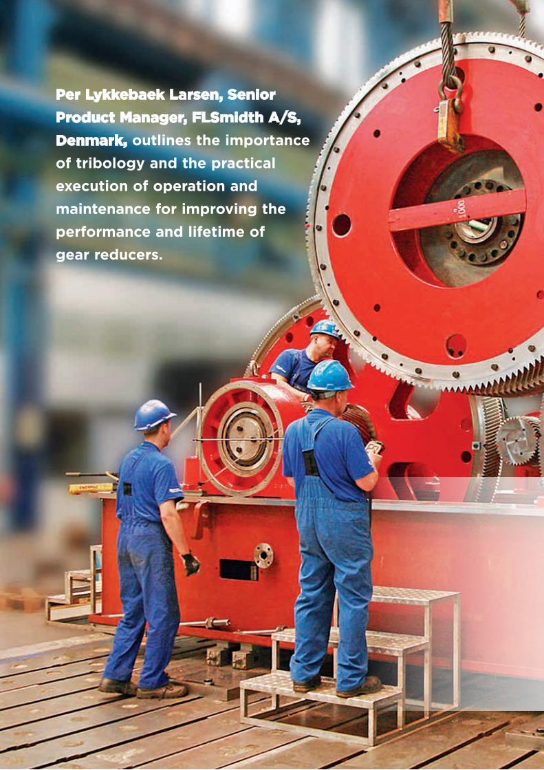
Per Lykkebaek Larsen, Senior
Product Manager, FLSmidth A/S,
Denmark, outlines the importance
of tribology and the practical
execution of operation and
maintenance for improving the
performance and lifetime of
gear reducers.
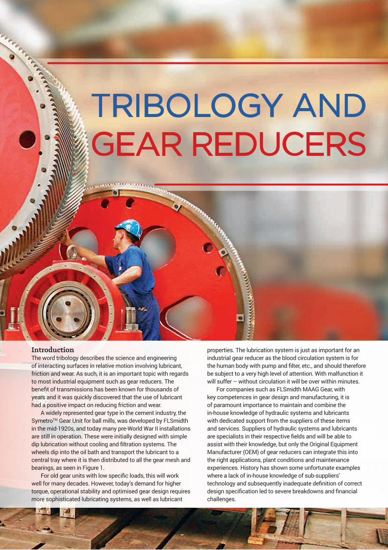
TRIBOLOGY AND GEAR REDUCERS
IntroductionThe word tribology describes the science and engineering of interacting surfaces in relative motion involving lubricant, friction and wear. As such, it is an important topic with regards to most industrial equipment such as gear reducers. The benefit of transmissions has been known for thousands of years and it was quickly discovered that the use of lubricant had a positive impact on reducing friction and wear.
A widely represented gear type in the cement industry, the SymetroTM Gear Unit for ball mills, was developed by FLSmidth in the mid-1920s, and today many pre-World War II installations are still in operation. These were initially designed with simple dip lubrication without cooling and filtration systems. The wheels dip into the oil bath and transport the lubricant to a central tray where it is then distributed to all the gear mesh and bearings, as seen in Figure 1.
For old gear units with low specific loads, this will work well for many decades. However, today’s demand for higher torque, operational stability and optimised gear design requires more sophisticated lubricating systems, as well as lubricant
properties. The lubrication system is just as important for an industrial gear reducer as the blood circulation system is for the human body with pump and filter, etc., and should therefore be subject to a very high level of attention. With malfunction it will suffer – without circulation it will be over within minutes.
For companies such as FLSmidth MAAG Gear, with key competences in gear design and manufacturing, it is of paramount importance to maintain and combine the in-house knowledge of hydraulic systems and lubricants with dedicated support from the suppliers of these items and services. Suppliers of hydraulic systems and lubricants are specialists in their respective fields and will be able to assist with their knowledge, but only the Original Equipment Manufacturer (OEM) of gear reducers can integrate this into the right applications, plant conditions and maintenance experiences. History has shown some unfortunate examples where a lack of in-house knowledge of sub-suppliers’ technology and subsequently inadequate definition of correct design specification led to severe breakdowns and financial challenges.

Lubrication purposeThe main purpose of the lubricant in gear reducers is to reduce friction and wear, cool/heat, clean and protect against corrosion. The aim is to maintain as large an oil film thickness as possible between the sliding surfaces, ensuring full fluid lubrication where the surfaces in action are completely separated at all times (Figure 2).
Whereas the oil film thickness is a function of several parameters, hereunder the load and the relative sliding velocity of the surfaces, there will always be a challenge in a gear reducer where the same lubricant must facilitate both the high speed as well as the low speed gearings. Therefore the low speed parts may be exposed to mixed or even boundary lubrication, resulting in increasing surface peak contacts, if
they have not been taken into consideration in the system design or the choice of lubricant.
By analysing tooth failures described in the gear norms3 with the typical root causes for gear reducers, it will show that the performance of the lubricating system and the oil has an impact on many of the potential failure types (Table 1).
It is the obligation of the gear designer and manufacturers to produce and supply the units according to the norms, lifetime and specification with the adequate application service factors and quality. Here, the advanced heat treatment and accuracy of the tooth profiles, helix, pitch deviation and run out are very important topics to control. With today’s state-of-the-art manufacturing processes, the final gear grinding, applicable for even the big gear wheels of the
SymetroTM Gear Unit, ensures that the quality of the teeth and surface roughness will meet a very high standard, reducing the risks related to time and quality shown in Table 1.
The oil flow and viscosity will have no direct influence on pitting formation; however, the consequence of inadequate levels will in time have an impact on damages related to fatigue surface stress. From Table 1, it can be seen that the root causes involving lubricants (oil level/flow, viscosity, additives and contamination) can initiate all types of failures, excluding cracks and electrical wear.
Most gear reducers are designed for mineral gear oils, but a synthetic alternative can under special circumstances be considered where the better temperature/viscosity behaviour, slower oxidation and lower internal friction justify this. In general, a mineral oil can be substituted (not mixed) with a synthetic PAO (Poly-alpha-olefin) oil, increasing the Viscosity Index (VI) from a typical 100 to approximately 150. If changing to a synthetic platform, it is very important to ensure that PG (poly-glycol) oil is not used unless the whole system is designed for this. PG oil with the VI typically exceeds 230, making it a very efficient lubricant. However, this can be rather problematic with regards to compatibility with the rubber sealings, painting and some non-ferrous materials.
Figure 1. SymetroTM Gear Unit with dip lubrication.1
Figure 2. Oil film thickness between magnified surfaces.2
Table 1. Tooth failure – root cause matrix1
Tooth failures (ANSI/AGMA 1010-E95)
Root cause
Pitting Cracks Adhesion Scuffing Abrasion wear
Polishing wear
Corrosion wear
Cavitation wear
Electrical wear
Time* X X
Quality* X X X X
Vibrations X X X X
Overload X X X X
Alignment X X X X X X
Inferior maintenance X X X X
Oil level/flow (X) X X
Viscosity (X) X X X X
Additives X X X X X X
Contamination X X X X X X X
* OEM duty
\Reprinted from December 2014World Cement
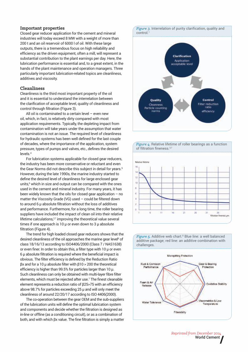
Important propertiesClosed gear reducer application for the cement and mineral industries will today exceed 8 MW with a weight of more than 200 t and an oil reservoir of 6000 l of oil. With these large outputs, there is a tremendous focus on high reliability and efficiency as the driven equipment, often a mill, will represent a substantial contribution to the plant earnings per day. Here, the lubrication performance is essential and, to a great extent, in the hands of the plant maintenance and operation managers. Three particularly important lubrication-related topics are cleanliness, additives and viscosity.
CleanlinessCleanliness is the third most important property of the oil and it is essential to understand the interrelation between the clarification of acceptable level, quality of cleanliness and control through filtration (Figure 3).
All oil is contaminated to a certain level – even new oil, which, in fact, is relatively dirty compared with most application requirements. Typically, the depleting impact from contamination will take years under the assumption that water contamination is not an issue. The required level of cleanliness for hydraulic systems has been well defined for the last couple of decades, where the importance of the application, system pressure, types of pumps and valves, etc., defines the desired levels.4
For lubrication systems applicable for closed gear reducers, the industry has been more conservative or reluctant and even the Gear Norms did not describe this subject in detail for years.5 However, during the late 1990s, the marine industry started to define the desired level of cleanliness for large enclosed gear units,6 which in size and output can be compared with the ones used in the cement and mineral industry. For many years, it has been widely known that the oils for closed gear application – no matter the Viscosity Grade (VG) used – could be filtered down to around 6 µ absolute filtration without the loss of additives and performance. Furthermore, for a long time, the roller bearing suppliers have included the impact of clean oil into their relative lifetime calculations,2,7 improving the theoretical value several times if one approach is 10 µ or even down to 3 µ absolute filtration (Figure 4).
The trend for high loaded closed gear reducers shows that the desired cleanliness of the oil approaches the marine gear level6 of class 18/16/13 according to ISO4406/2000 (Class 7 / NAS1638) or even finer. In order to obtain this, a filter type with 10 µ or even 6 µ absolute filtration is required where the beneficial impact is obvious. The filter efficiency is defined by the Reduction Ratio βx and for a 10 µ absolute filter with β10 > 200 the theoretical efficiency is higher than 99.5% for particles larger than 10 µ. Such cleanliness can only be obtained with multi-layer fibre filter elements, which must be rejected after use.7 The finest cleanable element represents a reduction ratio of β25>75 with an efficiency above 98.7% for particles exceeding 25 µ and will only meet the cleanliness of around 22/20/17 according to ISO 4406(2000).
The co-operation between the gear OEM and the sub-suppliers of the lubrication units will define the optimal lubrication system and components and decide whether the filtration is designed as in-line or offline (as a conditioning circuit), or as a combination of both, and with which βx value. The fine filtration is simply a matter
Figure 3. Interrelation of purity clarification, quality and control.1
Figure 5. Additive web chart.8 Blue line: a well balanced additive package; red line: an additive combination with challenges.
Figure 4. Relative lifetime of roller bearings as a function of filtration fineness.3,7
/Reprinted from December 2014
World Cement

of adequate filter size to obtain a suitable low pressure drop and a high dirt capacity to ensure the long lifetime of the elements.
AdditivesThe additives are the second most important property of the oil. The gear oil is tailor-made with a well-balanced additive package for advanced properties, which can meet the requirements of the industry. If just one of the additives fails it will have consequences for the oil performance. Typically, the depleting impact from non-performing additives will take months and a problem will typically be discovered either through the safety system (if up to date) or the regular oil analysis and can normally be corrected in due course. Different lubricant suppliers use different chemistry in their products, which is why it is strongly recommended not to mix two different brands (Figure 5).
The most commonly known is the Extreme Pressure (EP) additive, which creates a temperature ignited chemical reaction reducing or eliminating the micro welding of surface peaks during mixed or boundary lubrication. This is especially useful in the low speed gearings, as earlier mentioned, and this additive is often a mandatory requirement from the gear OEM. Another important additive is the friction modifier, which is a physical adhesion of slippery molecules to the metal surfaces. The friction modifier works only in a lower temperature range than the EP additives. Other important additives will reduce foam, improve VI, reduce oxidation (aging), maintain the emulsified water or protect the surfaces against corrosion.
ViscosityThe viscosity is the most important property of the oil. It describes the internal friction of the lubricant, which are categorised in different Viscosity Grades (VG) defined by the unit centi-Stoke (cSt [mm2/s]) at 40 ˚C.5 If the viscosity becomes inadequate, the equipment can be damaged within days or hours – or possibly even minutes. Along with the pressure and the relative speed, the viscosity has a tremendous impact on the oil film thickness. The level of viscosity is often represented by the temperature utilising the linear correlation in a single logarithmic diagram.
Whereas the oil according to the ElastoHydrodynamic Lubrication (EHL) theory9 will transform almost into solid lubricant in the microscopic pressure zone in a gear mesh with a theoretical viscosity of around 40 – 50 000 cSt, this will not help the gear reducer if the combination of pressure, relative speed and viscosity do not allow the oil film to build up before it reaches this solid stage.
The impact of both the relative velocity and the viscosity on the oil film thickness for a linear load (gear mesh and roller bearings) depends on the exponent 0.7, whereas the pressure has the impact of the exponent -0.13 only – see the following simplified equation:
hmin = X (v · V)0.7/p0.13
hmin => minimum oil film thicknessX => various parameters
v => viscosityV => relative speed
p => surface pressure
For a gear reducer using VG 320 oil, a typically allowable operating temperature can be between 50 ˚C (175 cSt) and 60 ˚C (105 cSt). The relative improvement of the oil film thickness by reducing the temperature from 60 ˚C to 50 ˚C is around 43% and will have a positive impact on the lifetime of the parts as expressed in Table 1 and Figure 4. Therefore, it is highly important to maintain the temperature within the specified levels and preferably in the low range. Neither the relative speed nor the pressure is normally a parameter that the gear operator can adjust or optimise.
The presence of water in the lubricant is considered as contamination and, if it reaches a certain level, the viscosity will decrease dramatically, consequently increasing the risk of gear damages. Water contamination cannot be avoided but must be kept as low as possible. Even relative low water content could cause problems such as surface corrosion, if the water turns from dissolved into emulsified/free phase when the temperature drops.11 Every specific lubricant has a characteristic saturation curve, which unfortunately is very difficult or impossible to get from the lubricant suppliers; however, if the water contamination is kept below 200 ppm, most of the lubricants will be safe at least down to 10 ˚C.
ConclusionFor owners of gear reducers, it is equally important to maintain in-house knowledge of the tribology terms and the practical execution of operation and maintenance, including being able to understand the systems and to have a reliable dialogue with the lubricant suppliers. It is vital to be able to read and understand an oil data sheet or an oil analysis using sound, objective judgment. For this reason, the OEM of gear reducers should take ownership in this education and offer this service via seminars and symposiums.1
Likewise, the OEM is obligated to ensure that the new development in the technology and safety devices becomes applicable for the technology of the past. For old SymetroTM Gear Units still going strong, a full retro-fit package has been developed by FLSmidth MAAG Gear, including new stronger spare parts, lubricating units with water saturation sensors, vibration monitors, etc., which will bring the gear reducers up front in the 21st century.
References1. FLSmidth International Maintenance Seminar 2014 (Lubrication &
Maintenance of Heavy Duty Gear Units).2. FAG, Schmierung von Wälzlagern, Publ.-Nr. WL 81115/5 DA.3. ANSI/AGMA 1010-E95.4. Danish Technological Institute, Industrial Technology and Chemistry
(Recommended Degrees of Purity and Filter Level).5. ANSI/AGMA 9005-E02.6. Dansk Standard DS 2395-1998 (1. udgave).7. Antriebstechnik 28 (89), 29 (90) and 31 (93).8. Mobilgear XMP Program, 1st edition (May 1999).9. Mobil EHL Guidebook – The ElastoHydrodynamic Lubrication.10. Lubrication of gears (Part 3) by Robert Errichello, GEARTECH, Albany,
Califonia.11. PALL Corporation Industrial Group, Practical Oil Analysis Technology,
Issue Number 200709.12. HYDAC Filtertechnik, Contamination Handbook, Prospekt-Nr.
7.603.2/07.04.
\Reprinted from December 2014World Cement

www.flsmidth.com
Project Centre Denmark FLSmidth A/SVigerslev Allé 77DK-2500 ValbyCopenhagenTel: +45 3618 1000Fax: +45 3630 1820 E-mail: [email protected]
Project Centre USAFLSmidth Inc. 2040 Avenue CBethlehem, PA 18017-2188Tel: +1 610-264-6011Fax: +1 610-264-6170E-mail: [email protected]
Project Centre IndiaFLSmidth Private LimitedFLSmidth House34, Egatoor, Kelambakkam(Rajiv Gandhi Salai, Chennai)Tamil Nadu – 603 103Tel: +91-44-4748 1000Fax: +91-44-2747 0301E-mail: [email protected]
Copyright © 2014 FLSmidth A/S. ALL RIGHTS RESERVED. FLSmidth is a (registered) trademark of FLSmidth A/S. This brochure makes no offers, representations or warranties (express or implied), and information and data contained in this brochure are for general reference only and may change at any time.