trenchless pipe laying - · pdf filebased on the mechanical strength and the angular...
TRANSCRIPT

Trenchless pipe laying
Comprehensive pipe systems

Ductile iron represents a reliable and advantageous alternative to the materials normally used in horizontal directional drilling. The sturdiness, modularity and durability of cast iron pipes is combined with proven technology to enable pipeline flexibility.
A little historyThe horizontal directional drilling technique appeared at the beginning of the 20th century but only started to interest the oil industry at the end of the 1920s. A large number of improvements, in particular to the guidance system and the drilling equipment was needed before it was possible to progress in the 1930s from drilling “at an angle” to true directional drilling that could follow a curved path.
The further improvement in the 1970s in hydraulics have enabled uninterrupted drilling and the pulling through of rods to a predetermined profile. With the development of location tools, horizontal directional drilling has truly become an effective technique.
3 types of implementationThe development of ductile iron pipeline anchoring techniques has enabled PAM to offer complete solutions for trenchless pipe laying.
Based on the mechanical strength and the angular deflection capability of Universal Ve self-anchored joints, PAM has chosen 3 trenchless pipe laying techniques:
horizontal directional drilling, pipe bursting and pulling into a sleeve.
Contents:Introduction 03
01 horizontal directional drilling
phase 1 : drilling the pilot hole 04
phase 2 : enlarging the pilot hole 06
phase 3 : pulling the pipe string 08
02 pipe bursting 10
03 pulling through a casing 12
04 the benefits of trenchless pipe laying 16
05 the PAM offer 18
06 anchoring technologies 20
07 the material 22
08 the PAM service 24
09 the PAM experience 26
10 the PAM range 28
Saint-Gobain PAM - DIREXIONAL - Edition 2012 32
Trenchless pipe laying
« There are places where being unobtrusive is paramount.»

01
A drilling machine located at the pipe’s exit point will carry out the pilot drill to the pipe string start point.An electronic sonde, located in the drilling head and coupled with a detection and guidance system will enable the planned path to be followed with great accuracy (+/- 5 centimeters).
Horizontal directional drilling enables a pipeline to pass under an obstacle, such as a canal, a river or a road. Unlike horizontal boring technique that require major excavation at both ends, the curved trajectory of horizontal directional drilling enables the pipeline to pass under obstacles starting from ground level.
Horizontal directional drilling performance depends on several factors:
� nature of the ground� stratigraphy� drilling radius� profile regularity� nature of the pipeline� installation footprint...
Each situation has its own solution!
Only certain soils remain unsuitable for the horizon-tal directional drilling technique (mainly liquefied clay and gravel) as the drilling heads are selected for conditions from soft ground to very hard rock such as granite or even basalt.
Drilling with 3 toolsThe drilling head, fitted with a cutting head suited to the ground, injection nozzles and a sonde, is driven by a string of hollow steel tubes: the drilling rods.
The drilling rods are used to:� push the drilling head� rotate the drilling head and its tools� direct curved drilling in a vertical and/or
horizontal direction� transport the drilling fluid� pull the boring tools� install the final pipeline
The transmitting sonde located in the drilling head continuously reports its altimetric and planimetric position. This enables the operator to guide the dril-ling accurately using the information they see on their screens.
Since the drilling head is asymmetric or fitted with independent rollers, its trajectory can be modified during continuing drilling.
There are different drilling tools suitable for the constraints presented by the ground encountered (boring head, enlarging cone, diamond tip, etc.).
Saint-Gobain PAM - DIREXIONAL - Edition 2012 54
Drilling the pilot holePipe laying by HDD* to DN 1000Simple and easy to use and supplied as 6 or 7 meters pipes, PAM pipes feature a TT (all-terrain) external barrier coating, suited to installation using horizontal directional drilling.
(*) Horizontal directional drilling
Horizontal directional drillingDrilling hole with bentonite and drill string
Pipe assembly and storage zone
DRILLING UNIT Truck with hydraulic unit, highpressure pumps, bentonite pumps
DTp
D
Phase 1

Did you know
Bentonite is a fine clay mixed with water to form drilling mud. This mud enables the drilling and boring tool to be cooled, consolidates the tunnel wall and even assists drilling due to pressure. It also contributes to the removal of spoil before the pipeline is pulled though. It is possible to slightly adjust the density of this product, sometimes during operation, to facilitate drilling and pulling. Drilling mud is generally recycled and used in a closed loop.
w
01
When the drilling head exits at the opposite end, it is replaced by a boring head that will be pulled in the opposite direction by the drilling unit. Traversing the pilot hole along the entire path, the boring head widens the hole diameter, adapting it to the dimensions required for the pipeline to pass through.
The bore diameter varies according to the diameter of the pipeline to be installed as well as the drilling length, the nature of the ground, the curve radius, etc. It may be necessary to carry out successive boring operations, using boring tools of increasing diameter, to obtain the correct diameter which is between 1.2 and 1.5 times the pipeline diameter.
The boring head is fitted with injection holes, like the drilling head. Injecting bentonite reduces the effects of heating and friction.
Recommendations:It is common practice to select the final bore diameter using the following data.
Length or type of drilling
Final boring diameter
less than 50 metres D 1.2 X D
from 50 to 100 metres D 1.3 X D
from 100 to 300 metres D 1.4 X D
more than 300 metres D 1.5 X D
drilling through rock D 1.5 X D
D = pipe socket outside diameter
Saint-Gobain PAM - DIREXIONAL - Edition 2012 76
Enlarging the pilot hole
Horizontal directional drilling
Where innovation combines with savings Horizontal directional drilling techniques are innovative in the field of saving energy, saving materials and recycling. Beyond the virtuous circle illustrated by bentonite treatment and reuse, horizontal direc-tional drilling enables a 4X reduction in greenhouse gas emissions compared to a traditional operation. (e.g. emission of 30 kg CO2e/linear metre of DN 150 pipeline when laid using horizontal directional drilling compared to 119 kg CO2e/linear meter when laid using an open trench).
Drilling hole with bentonite and drill string
Exit earthworks and pipe
assembly area
D
DRILLING UNIT Truck with hydraulic unit, high pressure pumps, bentonite pumps
DTpPhase 2
Did you knowModularityThe pipes can be pre-assembled as a full length string, pre-mounted in 3-pipe sections, or assembled pipe-by-pipe where site restrictions require. This modularity enables upstream constraints associated with the footprint of the project to be addressed. Ductile iron pipes can be laid in sections – a major benefit in this case.
w
01
Universal Standard Ve pipes resist very high pulling forces. That makes them the optimum solution for pipe laying using horizontal directional drilling.
Once the boring operation is complete, the tunnel remains filled with bentonite. This acts as an excellent lubricant and facilitates the pulling of pipes by redu-cing friction and force on the joints.
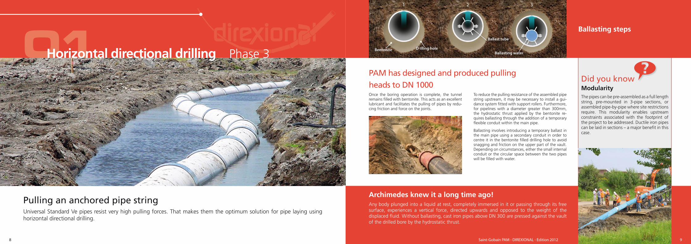
To reduce the pulling resistance of the assembled pipe string upstream, it may be necessary to install a gui-dance system fitted with support rollers. Furthermore, for pipelines with a diameter greater than 300mm, the hydrostatic thrust applied by the bentonite re-quires ballasting through the addition of a temporary flexible conduit within the main pipe.
Ballasting involves introducing a temporary ballast in the main pipe using a secondary conduit in order to centre it in the bentonite filled drilling hole to avoid snagging and friction on the upper part of the vault. Depending on circumstances, either the small internal conduit or the circular space between the two pipes will be filled with water.
Ballasting water
321
Bentonite Drilling hole
Ballast tube
Ballasting steps
rilliinngnitite
Ba
terer
Saint-Gobain PAM - DIREXIONAL - Edition 2012 98
Pulling an anchored pipe string
Horizontal directional drilling
Archimedes knew it a long time ago!Any body plunged into a liquid at rest, completely immersed in it or passing through its free surface, experiences a vertical force, directed upwards and opposed to the weight of the displaced fluid. Without ballasting, cast iron pipes above DN 300 are pressed against the vault of the drilled bore by the hydrostatic thrust.
PAM has designed and produced pullingheads to DN 1000
Phase 3
Pipe bursting exampleAt Chambon Feugerolles, near Saint-Étienne in France, this technique was used for an 80 linear metre section between 2 excavated pits to avoid damaging a paved courtyard in front of the town hall and interrupting the town’s summer events.
02
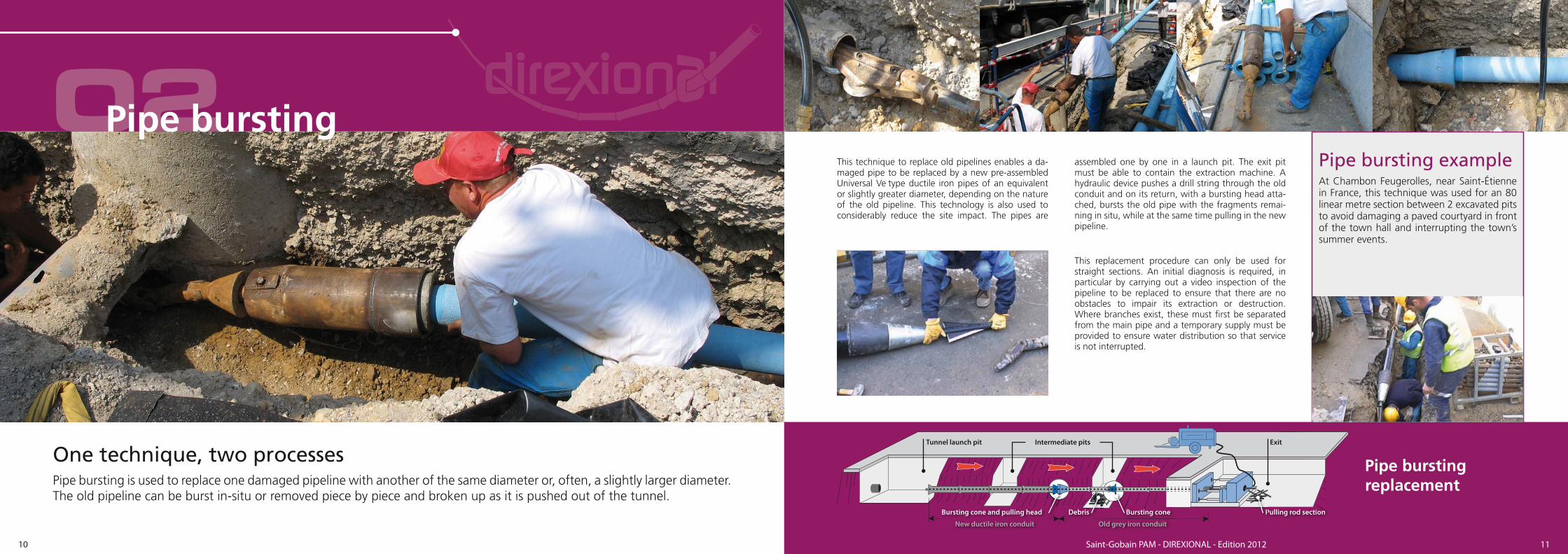
Pipe bursting is used to replace one damaged pipeline with another of the same diameter or, often, a slightly larger diameter. The old pipeline can be burst in-situ or removed piece by piece and broken up as it is pushed out of the tunnel.
This technique to replace old pipelines enables a da-maged pipe to be replaced by a new pre-assembled Universal Ve type ductile iron pipes of an equivalent or slightly greater diameter, depending on the nature of the old pipeline. This technology is also used to considerably reduce the site impact. The pipes are
assembled one by one in a launch pit. The exit pit must be able to contain the extraction machine. A hydraulic device pushes a drill string through the old conduit and on its return, with a bursting head atta-ched, bursts the old pipe with the fragments remai-ning in situ, while at the same time pulling in the new pipeline.
This replacement procedure can only be used for straight sections. An initial diagnosis is required, in particular by carrying out a video inspection of the pipeline to be replaced to ensure that there are no obstacles to impair its extraction or destruction. Where branches exist, these must first be separated from the main pipe and a temporary supply must be provided to ensure water distribution so that service is not interrupted.
Saint-Gobain PAM - DIREXIONAL - Edition 2012 1110
Pipe bursting
One technique, two processes Pipe burstingreplacement
Tunnel launch pit
Bursting cone and pulling head Debris Bursting cone Pulling rod section
New ductile iron conduit Old grey iron conduit
Intermediate pits Exit
PPBB

Did you knowFor pipes with a nominal diameter greater than 800mm or where there are specific difficulties, it is necessary to use special centring and guiding supports. Depending on the project specifics, PAM will investigate the creation of specific supports and arrange for subcontracting of their supply. With all these types of equipment, it is even possible to insert 2 pipelines within a single casing.
w
03
Pipe laying through a casing consists of introducing a pipeline intended to transport a fluid (drinking water, waste water, rain water, dry systems, etc.) within a circular sleeve that already exists or is installed specifically for this application. Ductile iron pipelines are perfectly suited to this application, since the anchored joints can withstand significant pulling forces, while retaining the flexibility offered by elastomer gaskets.
This laying method can be chosen for specific rehabi-litation techniques (passing through an existing da-maged pipe) or when laying new networks crossing a natural obstacle or in the case of trenchless works.
When pulling through a casing, you must first define:
� the centring and guiding of each element within the casing
� the method used to anchor the elements to-gether to guarantee the integrity of the section being installed
� the method used to connect the section passing through the casing to the existing network
� the best pulling mechanism from a technical and economic perspective
The choice of pipeline diameter will be guided either by determining the most suitable hydrau-lic diameter in the case of a new pipeline, or the
inside diameter of the existing pipeline or casing. In parallel, you must ensure that the annular space between the pipe and the casing is sufficiently large to enable the fitting of centring collars that meet the requirements for the guidance and pulling of the conduit within the casing. The nominal dia-meter chosen, along with the network operating pressure and the pulling force required will enable you to choose the most suitable range of pipes and anchoring method in the PAM range from DN 60 to DN 1200.
To begin with, an access pit or a pipe assembly area will be created where the pulling head anchoring and pipe connection operations can take place. Each pipe is then fitted with centring collars. Their number is first determined according to their mate-rial (plastic or metal) and their support capacity. The pipes are then positioned on a wooden or concrete guide along the casing axis.
The pulling device is installed on the first pipe that is then pulled into the casing, with the rear of the pipe overhanging slightly. Different types of pulling mechanisms can then be used depending on the type of pipes installed as well as the length of the string to be pulled. The second pipe is located on the guide and anchored to the first before in turn being pulled into the casing. The process of assem-bling and pulling the pipes continues until the re-quired length is in place. After pulling the last pipe, the pulling device is removed and tests carried out before connecting the new pipe at both ends.
Saint-Gobain PAM - DIREXIONAL - Edition 2012 1312
Pulling through a casing
Pulling through a casing
Important: the pipes must always be installed by pulling, never by pushing.
CasingCasing
Centring collar Weld bead
Hand winch for assemblys gs g
lararar d bbbbbe

04Lower social costs
� no interference with traffic
� no interruption to services
� less damage to the environment
� little or no risk of accidents
� little or no risk of economic consequences for local businesses
� less noise and air pollution for residents
An ideal solution for a site in a protected environment or an area with a high urban density
Lower indirect costs� fewer road signs needed
� less site security required
� no diversion costs for distributors
� no need to move street furniture
Savings compared to a traditional site.
Lower direct costs� more technical materials
� no back-filling or compacting, no need to repair roads and pavements, etc.
� lower equipment and lorry costs
� specialist workforce
� fewer personnel
� reduced project time
Significant savings compared to a traditional site.
Ductile iron has progressively taken its place in the field of horizontal directional drilling thanks to its economic, technical and environmental benefits.
Saint-Gobain PAM - DIREXIONAL - Edition 2012 1514
The benefits of trenchless pipe laying
Bonus: trenchless pipe laying significantly reduces greenhouse gas emissions.
An economical, durable and unobtrusive solution


Did you knowAt the end of its life, PAM pipelines have the significant benefit of being infinitely recyclable through local systems (collection and recovery of scrap metal). This benefit arises from the use of ductile iron, which is produced mainly from recycled materials and is itself 100% recyclable without losing its mechanical properties. This optimised re-use of materials makes the resource inexhaustible.
Furthermore, ductile iron produced from mineral sources is completely inert and non toxic.
w
05A la carte solutionsWith coatings adapted to the ground conditions and the purpose your pipelines will serve (sewage, distri-bution and transfer of drinking water), PAM offers its range of Universal Ve pipes coated with:
� Thick polyethylene until DN700
� Reinforced polyurethane for DN800 to 1000
� ZMU cement mortar until DN700 for rocky ground
For decades, PAM ductile iron’s reputation for strength, durability and reliability has been recognised worldwide.
Protective collar
Sealing chamber Anchoring chamber
r
Metal shell
ive coll
Metall sSaint-Gobain PAM - DIREXIONAL - Edition 2012 1918
The PAM offer
Ductile iron Universal Ve self-anchored joint: “a proven technology giving access to trenchless operations”.

Did you knowTo form a 30° curve, only 10 pipes are required!
06Angular deflection and curve radius
DN JointAngular
deflec tionPFA (bar)
Allowable curve
radius (m)
100 Uni Ve 3° 64 115
150 Uni Ve 3° 55 115
200 Uni Ve 3° 50 115
250 Uni Ve 3° 45 115
300 Uni Ve 3° 40 115
350 Uni Ve 3° 38 115
400 Uni Ve 3° 35 115
450 Uni Ve 3° 32 115
500 Uni Ve 3° 30 115
600 Uni Ve 2° 27 172
700 Uni Ve 2° 25 172
800 Uni Ve 2° 25 364
900 Uni Ve 1.5° 25 445
1000 Uni Ve 1.2° 25 572
Allowable pulling forces (kN)Pulling lengths (km)
DN 0 to 0,4 0.5 0.7 0.9 1 1.2
100 87 84 77 70 66 59
125 114 109 100 91 87 78
150 136 131 120 109 104 93
200 201 193 177 161 153 137
250 271 260 239 217 206 184
300 342 329 301 274 260 233
350 426 409 375 341 324 290
400 506 486 445 405 384 344
450 579 556 510 463 440 394
500 667 640 587 533 507 453
600 855 821 752 684 650 581
700 1000 961 881 801 761 681
800 * 1225 1177 1078 981 932 834
900 * 1473 1415 1297 1179 1120 1002
1000 * 1725 1657 1519 1381 1312 1174
For trenchless pipe laying, PAM has designed a particularly effective anchoring system which guarantees optimum sealing and flexibility while supporting pulling efforts as high as 100 tonnes for the largest diameters.
The maximum allowable pulling forces are esta-blished based on the maxi-mum pressure supported by the Universal Ve self-anchored joints.
These values are subject to reduction by taking into account the specific dyna-mic constraints of each individual project (conti-nuous pulling, pulling by pre-assembled section, pulling pipe by pipe).
(*) Allowable pulling forces for pipelines DN 800, DN 900 and DN 1000The values in the table are for information only. Large diameter projects require all elements specific to the project to the taken into account, in particular the profile along its length, geotechnical data and pipe laying constraints. Only recommendations defined by PAM will be binding.
R
�d
�
��
L
Saint-Gobain PAM - DIREXIONAL - Edition 2012 2120
A high security technologyDuctile iron + self-anchored joint + liner + metal shell
= solidity + flexibility + leak tightness!
Anchoring technologies

Did you knowAll PAM joints are protected by a metal shell to guarantee that the elastomer liners will be held in place, particularly in the event of accidental rubbing against the vault during pulling.
w
Types of drilling rig Pulling force in kNMaximum torque in
kN.mMass to be pulled in
tonnesMaximum pipe string
length
N°10 : Mini ≤ 150 10 – 15 < 10 E.g.: 500 linear
metres in DN 100
N°11 : Midi > from 150 to ≤ 400 15 – 30 10 – 25 E.g.: 500 linear
metres in DN 300
N°12 Maxi > from 400 to ≤ 2500 30 - 100 25 –60 E.g.: 500 linear
metres in DN 450
N°13 : Méga > 2500 > 100 > 60 DN > 500
07Drill performance
Depending on the diameter of the pipes to be laid, the length of the path and the nature of the soil, different types of drilling rig must be used.
In the pipeline laying field, PAM uses advanced technology that comes directly from oil drilling techniques.
Advanced technology
Saint-Gobain PAM - DIREXIONAL - Edition 2012 2322
The material
Drill utilisation guide:SAFETY, SITE ORGANISATION, FEEDBACK.
These themes are all covered in the best practice guide issued by SOFFONS(*)(*) Syndicat des Entrepreneurs de Sondages, Forages et Fondations Spéciales - the Union of Surveying, Drilling and Special Foundations Contractors.

Did you knowThe Moselle river was crossed by a DN 150 pipeline over a length of 210m. The work was carried out by a drilling machine with a capa-city of 20 tonnes.
Operations to carry out drilling, boring, deli-ver and remove the equipment were comple-ted in a little less than 4 days. The operation to pull pre-assembled pipes itself took less than 3 hours. The final 450mm boring took place in a sandy gravel soil.
w
08The PAM product offering has been progressively enhanced by service solutions. These are offered before projects, with calculation support for desi-gners, as well as later, with pipe laying teams trai-ned by our technicians.
Sales engineering teams and business managers have access to tools and utilities enabling them to examine technical dossiers in detail, accurately calculate allo-wable pulling forces, the safety coefficients offered as well as the parameters required to ballast the pipe.
Each study is considered to be unique and is carried out with the engineering consultants responsible for project design.
All projects are supported by customised assistance and the initial technical project study guarantees the success of the pulling operation.
From research to implementation
10
065 190
Length in metres
Height in m
etres
90 215115 240140 265165 290
20
R>RminRminPossible path
Saint-Gobain PAM - DIREXIONAL - Edition 2012 2524
The PAM service
Projects examined by our sales engineering teams are carried out according to the ISO 13470(*) standard and comply with the French Guide of Practice
Fascicule 70 relating to initial geotechnical research.(*) Trenchless applications of ductile iron pipe systems - Product design and installation

Did you knowPAM records
Lieu Longueur DN Année
The longest
Hamburg Germany
1500 m 150 2003
The largest
diameter in Europe
The Netherlands
330 m 800 2004
The largest
diameter in France
Lille 240 m 700 2006
w
09Initially developed in Europe for the German market, combining the trenchless pipe laying technique with PAM products has continued to develop.
Operating in the trenchless field in France for more than 20 years, PAM has been the supplier to more than 250 construction sites in Europe, the largest in terms of diameter being in the Netherlands (DN 800). With lengths varying between 25 and 1500 linear metres (DN 150), this process can meet the requirements of all projects.
With more than 20 years working in the field of trenchless pipe laying, PAM has gained sufficient experience to operate on the most technically demanding sites.
0
10
20
30
40
50
DN800
DN700
DN600
DN500
DN450
DN400
DN350
DN300
DN250
DN200
DN150
DN100
0
100
200
300
400
500
600
700
800
DN800
DN700
DN600
DN500
DN450
DN400
DN350
DN300
DN250
DN200
DN150
DN100
Saint-Gobain PAM - DIREXIONAL - Edition 2012 2726
The PAM experience
More than 90,000 linear metres of PAM pipes have been laid to-date using horizontal directional drilling.The equivalent of 2 Channel tunnels!
Many references, one expertise
Number of HDD operations by DN Average length in m by DN

DIREXIONAL TT PE and TT PUX pipes
(normal situations)
DN mm
L
mm
e
mm
DE
mm
B
mm
Mass
kg
Exterior
coating
Part no.
100 5.95 6.0 118.0 188.0 118 TT PE 227925
125 5.95 6.0 144.0 215.0 147 TT PE 227926
150 6.00 6.0 170.0 230.0 175 TT PE 227928
200 5.96 6.3 222.0 290.0 241 TT PE 227929
250 5.95 6.8 274.0 350.0 320 TT PE 227937
300 5.95 7.2 326.0 408.0 405 TT PE 227938
350 5.97 7.7 378.0 463.0 512 TT PE 227945
400 5.97 8.1 429.0 510.0 602 TT PE 227946
450 5.97 8.6 480.0 570.0 718 TT PE 228956
500 5.97 9.0 532.0 625.0 833 TT PE 227947
600 5.97 9.9 635.0 740.0 1067 TT PE 227948
700 5.97 10.8 736.6 855.0 1399 TT PE 227949
800 6.88 11.7 840.4 980.0 1941 TT PUX 229157
900 6.87 12.6 943.2 1087.0 2367 TT PUX 229158
1000 6.88 13.5 1046.0 1191.0 2814 TT PUX 229160
Sewage and Wastewater: INTEGRAL range - available upon request
DIREXIONAL TT ZMU pipes
(for rocky soils)
DN mm
L
mm
e
mm
DE
mm
B
mm
Mass
kg
Exterior
coating
Part no.
100 5.97 6.0 128.0 196.0 133.5 TT ZMU 224302
125 5.97 6.0 154.0 225.0 166.0 TT ZMU 224303
150 5.97 6.0 180.0 251.0 195.4 TT ZMU 224305
200 5.97 6.3 232.0 307.0 268.1 TT ZMU 224307
250 5.97 6.8 284.0 367.0 353.5 TT ZMU 224308
300 5.97 7.2 336.0 425.0 445.5 TT ZMU 224309
350 5.97 7.7 378.0 480.0 527.0 TT ZMU 224310
400 5.97 8.1 439.0 535.0 650.3 TT ZMU 224311
500 5.97 9.0 542.0 647.0 891.4 TT ZMU 224312
600 5.97 9.9 645.0 750.0 1135.4 TT ZMU 224313
700 5.97 10.8 748.0 865.0 1392.8 TT ZMU 224314
Nature of coatingsTT PE: extruded HDPE coating thickness: 2.00 to 2.50mm according to DNTT PUX : reinforced polyurethane coating thickness: 1,800μmTT ZMU : cement mortar coating thickness : 5,00mm
Universal Ve self-anchored joints
DN mm
EPDM Standard gasket Metal locking ring
Part no. Mass (kg) Part no. Mass (kg)
100 JSB10BA 0.196 110259 0.500
125 JSB12BA 0.244 124151 0.700
150 JSB15BA 0.285 AKB15E 0.900
200 JSB20BA 0.384 AKB20E 1.300
250 JSB25BA 0.497 AKB25E 1.300
300 JSB30BA 0.712 AKB30E 1.800
350 JSB35BA 0.898 JKB35E 2.300
400 JSB40BA 1.077 JKB40E 3.600
450 JSB45BA 1.323 JKB45E 4.050
500 JSB50BA 1.544 JKB50E 4.600
600 JSB60BA 2.162 JKB60E 8.600
700 JSB70BA 2.871 110671 9.700
800 JSB80BA 3.670 JFB80S 17.300
900 JSB90BA 4.612 JFB90S 22.600
1000 JSC10BA 5.588 JFC10S 24.800
Ø B
Ø D
I
Ø D
E
P Lu
e
c
EN 545C30 EN 15189
ISO 2531
Ø B
Ø D
I
Ø D
E
LuP
e
c
UNIVERSAL TT PE
EN 545
EN 14628C64
DVGW
CANALISATIO NSAINT-GOBAIN
ISO 2531
Ø B
Ø D
I
Ø D
E
LuP
ee1
c
Ø A
Ø B
L
No hole in DN600 and 700
Link with pins
Ø AØ B
L
Ø AAØ B
Ø
LL33
100
Ø A
Ø B
L
62200
1010
Saint-Gobain PAM - DIREXIONAL - Edition 2012 2928
The PAM range
TT PE – DN 100 to DN 700 TT PUX – DN 800 to DN 1000 TT ZMU – DN 100 to DN 700
DN 100 to 200 DN 250 to 350
Universal Ve metal retaining rings
DN 400 to 700 DN 800 to 1200
Assembly/dismantling accessories and toolsPlease contact our sales and sales engineering teams
HDD metal protection cone
DN mm
Part no. Mass
kg
Width
mm
Thickness
mm
100 110326 0.70 120 1.00
125 209752 0.75 120 1.00
150 110325 0.85 120 1.00
200 110324 1.20 130 1.00
250 110323 1.50 140 1.00
300 110322 1.80 155 1.00
350 207176 2.80 160 1.20
400 110321 3.00 170 1.20
450 211369 3.20 170 1.20
500 110320 3.50 180 1.20
600 110327 5.00 195 1.20
700 110328 6.00 210 1.20
800 228265 8.00 192 1.50
900 228268 11.70 285 1.50
1000 228270 9.00 192 1.50
TT PE & TT PUX elastomeric muff
DN mm
Exterior
coating
Part no. Type
100 PE JSB10YAT TT PE muff
125 PE JSB12YAT TT PE muff
150 PE JSB15YAT TT PE muff
200 PE JSB20YAT TT PE muff
250 PE JSB25YAT TT PE muff
300 PE JSB30YAT TT PE muff
350 PE 158071 Tubular sleeve
400 PE 158080 Tubular sleeve
450 PE 158094 Tubular sleeve
500 PE 158094 Tubular sleeve
600 PE 123649 Tubular sleeve
700 PE 211186 Tubular sleeve
800 PUX 30 m roll réf. 158030
+ band (x50) réf. 158098
Band & roll
900 PUX Band & roll
1000 PUX Band & roll
Pulling head for horizontal directional drilling
DN mm
Part no. Part no. Type Mass
kg
100 173371 - E01 Universal Tis-K One piece 21.00
125 177688 - E01 Universal Tis-K One piece 21.00
150 177686 - E01 Universal Tis-K One piece 31.00
200 177685 - E01 Universal Tis-K One piece 42.00
250 177684 - E01 Universal Tis-K One piece 70.00
300 177683 - E01 Universal Tis-K 2 pieces 200.00
350 177689 - E01 Universal Ve 2 pieces 260.00
400 215720 - E01 Universal Ve 2 pieces 290.00
450 184694 - E01 Universal Ve 2 pieces 370.00
500 215792 - E01 Universal Ve 2 pieces 445.00
600 215897 - E01 Universal Ve 2 pieces 604.00
700 215988 - E01 Universal Ve 2 pieces 1050.00
800 229305 Universal Ve 2 pieces 1450.00
900 229307 Universal Ve 2 pieces 1920.00
1000 229309 Universal Ve 2 pieces 2110.00
TT ZMU elastomeric muff
DN mm
Exterior
coating
Part no. Type
100 TT ZMU 110823 ZMU muff
125 TT ZMU 173263 ZMU muff
150 TT ZMU 110821 ZMU muff
200 TT ZMU 110822 ZMU muff
250 TT ZMU 110828 ZMU muff
300 TT ZMU 110834 ZMU muff
350 TT ZMU 110789 ZMU muff
400 TT ZMU 110750 ZMU muff
500 TT ZMU 110773 ZMU muff
600 TT ZMU 110776 ZMU muff
700 TT ZMU 110026 ZMU muff
1010
30 Saint-Gobain PAM - DIREXIONAL - Edition 2012 31
The PAM range
Accessories and assembly/dismantling toolsPlease contact our sales and sales engineering teams
elastomeric muff heat-shrink sleeve

www.pamline.com
SAINT-GOBAIN PAMHead office91, avenue de la Libération54076 NANCY CEDEXFRANCE
Marketing Department – Water & Sewage21, avenue Camille Cavallier54705 PONT-A-MOUSSON CEDEXFRANCEPhone: +33 (0)3 83 80 67 89
FOCA
LYS
– IM
PRIM
ERIE
MO
DER
NE
- DIV
-CAT
-07A
– 04
/201
2
li
SAINT-GOBAIN PAM worldwide
ALGERIASAINT-GOBAIN PAM ALGERIEZ.I. Sidi Abdelkader-Ben Boulaid - BP 53809000 - BLIDA - AlgeriaPhone: + 213 (0) 25 36 00 60
ARGENTINASAINT-GOBAIN PAM ARGENTINABouchard y Enz1836 - LLAVALLOL - BUENOS AIRES - Argentina Phone: + 54 11 42 98 9600
AUSTRALIASAINT-GOBAIN PAM15 Edgars RoadTHOMASTOWN VIC 3074 - AustraliaPhone: + 61 (0) 3 9358 6122
AUSTRIASAINT-GOBAIN GUSSROHRVERTRIEB ÖSTERREICH GmbHArchenweg, 52A-6020 - INNSBRUCK - AustriaPhone: + 43 512 341 717-0
BELGIUMSAINT-GOBAIN PIPE SYSTEMSRaatshovenstraat, n°2B-3400 - LANDEN - BelgiumPhone: + 32 11 88 01 20
BRAZILSAINT-GOBAIN CANALIZACAO LTDAPraia de Botafogo 440 7° andar 22250-040 - RIO DE JANEIRO - RJ - BrazilPhone: + 55 21 2128 1677
CHILESAINT-GOBAIN PAM CHILEAntillanca Norte 600Parque Industrial Vespucio, Comuna de PudahuelSANTIAGO DE CHILE - ChilePhone: + 562 444 13 00
CHINASAINT-GOBAIN PAM CHINA (SHANGAI)1812 Ocean Tower 550 Yan'An East Road - SHANGAI 200001 - ChinaPhone: + 86 21 6361 2165
SAINT-GOBAIN PAM CHINA (XUZHOU)Dong Jiao YangzhuangPC 221004 - XUZHOU - Jiangsu Province - ChinaPhone: + 86 516 8787 8107
SAINT-GOBAIN PAM CHINA (MAANSHAN)Hua Gong Road CihuPC 243052 - MAANSHAN Anhui Province - ChinaPhone: + 86 555 350 8040
COLOMBIASAINT-GOBAIN PAM COLOMBIATerminal terrestre de carga de BogotaEtapa 1, Bodega 9, Modulo 3Km 3,5 costado sur autopista - MedellinCOTA CUNDINAMARCA - ColombiaPhone: + 57 (1) 841 5832
CZECH REPUBLICSAINT-GOBAIN PAM CZ s.r.o.Po ernická 272/96108 03 Praha 10 - Czech RepublicPhone: + 296 411 746
FINLANDSAINT-GOBAIN PIPE SYSTEMS OYNuijamiestentie 3AFIN-00400 - HELSINKI - FinlandPhone: + 358 207 424 600
FRANCE & DOM-TOMSAINT-GOBAIN PAM (HEAD OFFICE)91 Avenue de la Libération54076 NANCY CEDEX - FrancePhone: +33 3 83 95 20 00
SAINT-GOBAIN PAM (France Commercial Department)CRD – Chemin de Blénod – B.P. 10954704 PONT A MOUSSON CEDEX - FrancePhone: +33 3 83 80 73 00
SAINT-GOBAIN PAM (Europe and International Commercial Departments)21 avenue Camille Cavallier54705 - PONT A MOUSSON CEDEX - FrancePhone: + 33 3 83 80 67 89
SAINT-GOBAIN PAM (Local Agency of The Antilles)Rue Alfred Lumière - ZI de Jarry - BP 210497122 - BAIE MAHAULT - GuadeloupePhone: + 33 590 26 71 46
SAINT-GOBAIN PAM (Local Agency of Indian Ocean)16, Rue Claude Chappe - ZAC 200097420 - LE PORT - Reunion IslandPhone: + 33 262 55 15 34
GERMANYSAINT-GOBAIN PAM DEUTSCHLANDSaarbrucker Strasse 5166130 - SAARBRUCKEN - GermanyPhone: + 49 681 87 010
GREECESAINT-GOBAIN SOLINOURGEIA5 Klissouras Str.GR 14482 - METAMORFOSI - ATHENS - Greece Phone: + 30 210 28 31 804
HONG KONGSAINT-GOBAIN PIPELINES H15/F Hermes Commercial Centre - 4-4A Hillwood RoadTSIM SHA TSUI - KOWLOON - Hong KongPhone: + 852 27 35 78 26
INDIASAINT-GOBAIN PAM Grindwell Norton Ltd5th Level, Leela Business Park - Andheri-Kurla RoadMUMBAI - 400059 - IndiaPhone: + 91 22 402 12 121
ITALYSAINT-GOBAIN PAM ITALIA SPAVia Romagnoli n°6I-20146 - MILAN - ItalyPhone: + 39 02 42 431
JORDANSAINT-GOBAIN PAM REGIONAL OFFICE Abu Zaid Center - Office # 835 Saad Bin Abi Waqqas St, - PO BOX 83100011183 AMMAN - JordanPhone: + 962 6 551 4438
MOROCCOSAINT-GOBAIN PAM REGIONAL OFFICE2 allée des Figuiers - Aïn SebaâCASABLANCA - MoroccoPhone: + 212 522 66 57 31
MEXICOSAINT-GOBAIN PAM MEXICOHORACIO 1855-502 - Colonia Los Morales - Polanco11510 - MEXICO D.F. - MexicoPhone: + 52 55 5279 1657
NETHERLANDSSAINT-GOBAIN PIPE SYSTEMSMarkerkant 10-171316 - AB ALMERE - NederlandPhone: + 31 36 53 333 44
NORWAYSAINT-GOBAIN BYGGEVARER ASDIvision PAM NorgeBrobekkveien 840582 - OSLO - NorwayPhone: + 47 23 17 58 60
PERUSAINT-GOBAIN PAM PERUAvenida de los Faisanes N° 157 - ChorillosLIMA 09 - PeruPhone: + 511 252 40 34/35
POLANDSAINT-GOBAIN CONSTRUCTION PRODUCTS POLSKA SP Z.O.O - PAM Business UnitUI. Cybernetyki 21PL-02-677 WARSZAWA - PolandPhone: + 48 22 751 41 72
PORTUGALSAINT-GOBAIN PAM PORTUGALEst. Nac. 10 - Lugar de D. Pedro -Apartado 1708P-2691-901 - SANTA IRIA DE AZOIA - Portugal Phone: + 351 218 925 000
ROMANIASAINT-GOBAIN CONSTRUCTION PRODUCTS ROMANIA S.R.L. - PAM Business UnitStrada Tipografilor nr. 11-15, Corp 84,Etaj 3, Birourile 323-338, Sector 1,BUCHAREST - RomaniaPhone: + 40 21 207 57 37
SLOVAKIASAINT-GOBAIN CONSTRUCTION PRODUCTS PAM Business UnitStara Vajnorska 13983104 - BRATISLAVA - SlovakiaPhone: + 421 265 45 69 61
SOUTH AFRICASAINT-GOBAIN CONSTRUCTION PRODUCTS PAM Business UnitN1 Business Park Corner Olievenhoutbosch Road & Old Johannesburg Road Samrand - PO BOX 700 GERMISTON - South Africa 1400Phone: +27 12 657 2800
SPAINSAINT-GOBAIN PAM ESPANA SAPaseo de la Castellana n°77 - Edificio Ederra - Planta 10E-28046 - MADRID - SpainPhone: + 34 91 397 20 00
UNITED ARAB EMIRATESSAINT-GOBAIN PAM PO BOX 47102 - Building N° 1092 - Villa N° 7Muroor Road - ABU DHABI - United Arab Emirates Phone: + 971 2 448 20 10
UNITED KINGDOMSAINT-GOBAIN PAM UKLows Lane - Stanton-by-DaleILLKESTON - DERBYSHIRE - DE7 4QUUnited KingdomPhone: + 44 115 930 5000
VIETNAMSAINT-GOBAIN PAM 201-203 Cach Mang Thang 8, Ward 4 - District 3HO CHI MINH CITY - VietnamPhone: +84 8 39 30 72 74