trencher 60/70
TRANSCRIPT

1
ENGLISH
E-1
TRENCHER 60/70

2
ENGLISH

3
ENGLISH
“EC” DECLARATION OF CONFORMITY
SS IIMMAA ,, SS ..AA ..
Polígono Industrial Juncaril, C/ Albuñol, Parcela 250 C.P. 18220 Albolote, Granada (SPAIN) Company responsible for the manufacturing and commercialisation of the below specified machine:
FLOOR SAW
DECLARES:
That the already mentioned machine, a floor saw designed to cut joints onto asphalt, concrete surfaces and other road works is in conformity with the provisions of the following EC directives (2006/42/CE machine directive) of the European Parliament: 2000/14/CE; 2002/44/CE; 2002/95/CE; 2002/96/CE
Applicable Standards:
UNE-EN 292-1; UNE-EN 292-2; UNE-EN 294; UNE-EN 349; UNE-EN 500-1; UNE-EN 13862:2002+A1=2009 UNE-EN 1050; UNE-EN 953
Details of the authorized person to elaborate the technical file Eugenio Fernández Martín Technical Manager SIMA S.A. Polígono Industrial Juncaril, C/ Albuñol, Parcela 250 - 18220 Albolote, Granada (SPAIN) Signed Albolote 01.01.2010 Managing Director
Javier García Marina

4
ENGLISH

5
ENGLISH
ÍNDICE
“EC” DECLARATION OF CONFORMITY ............................................................ 3
1. GENERAL INFORMATION. .......................................................................... 6
2. DESCRIPTION OF THE MACHINES .............................................................. 6
2.1 PICTOGRAMAS. ........................................................................................................ 7
3. TRANSPORT. .............................................................................................. 8
4. ASSEMBLING INSTRUCTIONS. ................................................................... 8
4.1 DELIVERY CONDITIONS ............................................................................................. 8
5. RECOMENDACIONES DE SEGURIDAD Y MEDIDAS DE PREVENCIÓN ............ 8
5.1 PROYECCIÓN DE FRAGMENTOS Ó PARTÍCULAS. .............................................................. 9
5.2 ATRAPAMIENTO POR O ENTRE OBJETOS. ....................................................................... 9
5.3 CONTACTOS TÉRMICOS. ............................................................................................ 9
5.4 INHALACIÓN, INGESTIÓN Y CONTACTOS CON SUSTANCIAS PELIGROSAS. ........................... 9
5.5 EXPLOSIONES E INCENDIOS. ...................................................................................... 9
6. PARTES DE LA MAQUINA. ........................................................................ 10
7. STARTING AND USING INSTRUCTIONS. ................................................... 11
7.1 WATER TANK......................................................................................................... 11
7.2 FITTING THE BLADE ................................................................................................ 11
7.3 CUTTING WITH A SINGLE BLADE ............................................................................... 12
7.4 CUTTING WITH TWO BLADES AT ONCE ....................................................................... 12
7.4.1 60 CM width cutting ..........................................................................................................12
7.4.2 70 CM width cutting ..........................................................................................................12
7.4.3 65 CM width cutting ..........................................................................................................12
7.5 ADJUSTING DEPTH OF CUTTING ................................................................................ 13
7.6 CUTTING FEED ...................................................................................................... 13
7.7 ADJUSTMENT HANDLEBAR........................................................................................ 13
7.8 PARKING BRAKE .................................................................................................... 14
7.9 CUTTING GUIDE..................................................................................................... 14
7.10 SHUTTING THE ENGINE DOWN .................................................................................. 15
7.11 START. ON / OFF ................................................................................................... 15
7.12 CUTTING MATERIALS............................................................................................. 15
7.13 SAFETY RECOMMENDATIONS & PREVENTION MEASURES............................................... 16
8. MANTENIMIENTO. ................................................................................... 16
8.1 TENSE & REPLACING THE BELTS. ............................................................................... 17
9. SOLUTIONS TO MOST FREQUENT ANOMALIES. ........................................ 18
10. CARACTERÍSTICAS TÉCNICAS. ............................................................... 18
11. WARRANTY. ........................................................................................... 19
12. SPARE PARTS. ....................................................................................... 19
11. ENVIRONMENT PROTECTION. ................................................................ 19
12. NOISE LEVEL DECLARATIONS. ............................................................... 19
13. VIBRATIONS LEVEL DECLARATIONS. ..................................................... 19
14. ELECTRICAL SCHEMES ........................................................................... 20
WARRANTY CERTIFICATE ............................................................................ 23
6
ENGLISH
1. GENERAL INFORMATION.
ATTENTION: Please read and understand perfectly the present instruction before using the machine.
SIMA S.A. thanks you for purchasing the FLOOR SAW model TRENCHER 60-70
This manual provides you with the necessary instructions to start, use, maintain and repair the floor saw. All aspects as far as the safety and health of the users is concerned have been stated. Respecting all instructions and recommendations assures safety and low maintenance. As such, reading this manual carefully is compulsory for any person responsible for the use, maintenance or repair of this machine.
As such, reading this manual carefully is compulsory for any person responsible for the use, maintenance or repair of this machine.
It is recommended to have always this manual in an easily accessible place where the machine is being used.
2. DESCRIPTION OF THE MACHINES
• The floor saws SIMA S.A., model TRENCHER 60-70, are designed and manufactured to cut onto flat surfaces asphalt, concrete, terrazzo, granite or ceramics sing one blade or two blades. High-speed diamond blades are used and advancement is manual.
Any misuse given to the floor saw will be considered as inappropriate and hazardous and remains forbidden
• Its constructive characteristics are: adjusting the cutting height using a handle or a wheel that can be blocked with an element to impede any undesirable movement.
• Emergency stop button situated in the control board.
• Water tank with the possibility to connect the machine to the main water inlet.
• Flexible rubber tires and aluminium rims with double pillow block bearings.
• Blade protection included and blade water cooling with water tape to control the water flow.
• The machine is run by a combustion motor to generate the movement of the cutting blade.
• The accelerator of the motor is remotely controlled.
• The floor saw has 4 wheels.
• The progress of the machine can be made by pushing on the machine, or through a wheel that transmits movement to the machine with chain drive and gears, this transmission is protected by a comprehensive backup prevents access to the moving parts.
• The frame is coated with a highly resistance anti-corrosion epoxy, polyester paint
• The machine is furnished with an anti-splatter screen in the cutting blade safeguard to avoid water splashes towards the backward cutting area of the machine.
• Guiding pointer to as check the straightness of the cutting
• The machine has transmission pulleys and a flexible belt. The transmission is protected by a safeguard to avoid any Access to the moving elements
• The chassis has elements of elevation to facilitate the transport of the machine.
• In height-adjustable handlebars offering comfort and ease of conduction to the operator.
• A graduated scale indicating the cutting depth.

7
ENGLISH
2.1 PICTOGRAMAS.
Pictograms included in the machine entail the following:
IS REQUIRED READ INSTRUCTIONS MANUAL. IS REQUIRED USE HELMET AND EYE AND EAR DEFENDERS. IS REQUIRED USE SAFETY GLOVES. IS REQUIRED USE SAFETY FOOTWEAR.
POSITION OF THE BRIDLES FOR DIFFERENT CUTTING WIDTHS.
ENTRY NOT ALLOWED TO PERSONS OUTSIDE THE LABOR, WARNING CUTTING TOOL.
LIFTING EYE.
NOISE LEVEL.
SAFETY WARNINGS AND STARTUP PROCEDURE.
TURNING THE WHEEL CLOCKWISE THE MACHINE DESCENDS.
TURNING THE WHEEL COUNTERCLOCKWISE THE MACHINE RISE.

8
ENGLISH
3. TRANSPORT.
For short distances, the floor saw TRENCHER 60-70 can be transported onto its own wheels. Raise the blade fully and move the saw manually.
When the machine must be lifted, use the hook located on the front part. It will be then easy to fix steel cables or chains (Fig. 2). The transport to be used should ensure the machine safety.
WARNING: use highly- resistant cables or chains (bear in mind the weight of the machine and see the metal label of the machine, Fig. 2).When you put down the machine, do it gently and avoid any strong bumps on the wheels that could damage other components.
4. ASSEMBLING INSTRUCTIONS.
4.1 DELIVERY CONDITIONS
The different versions of floor saws TRENCHER 60-70 models are supplied and single-packed suitable for safe transport. When removing the package, you should find the machine with no blade, no fuel and a bag with the following items:
• Kit of keys, keeping book and change blade instruction. • A manual of the machine and its warranty. • Instruction engine book.
5. RECOMENDACIONES DE SEGURIDAD Y MEDIDAS DE PREVENCIÓN
Avoid spilling fuel over the machine when filling the deposit because it can be dangerous and could affect some of its elements.
Before starting the engine, check oil level at the crankcase, placing the machine on a flat surface with the engine off. If needed, fill up to the required level with the oil recommended by the engine manufacturer.
• Fill the fuel deposit in a ventilated place, taking care not to do it in excess.
• Avoid inhaling the steam created when filling the deposit.
• Avoid spilling fuel and keep always in mind this procedure when filling the fuel deposit, the steams and the spilled fuel can be highly flammable under certain circumstances and can catch fire. If some fuel is spilled it must be cleaned and the steams dissipated before starting the engine.
• Do not smoke when filling the deposit and avoid the presence of sparks and fire even at the place where the fuel is storaged.
• Do not place flammable elements on the engine.
• Avoid the contact of the fuel with your skin.
• Do not allow the use of the engine without having the necessary instructions.
• Do not allow anyone to touch the engine when it is hot, it could cause burns on the skin.
• Do not allow children and pets to get close to the engine.
• Keep the fuel out of reach of children.
• Do not fill up while the engine is running and do not smoke while doing it. Try to do it in a place with good ventilation.
• Do not start the machine if you notice there are some anomalies that could affect the safety of the persons around.
• Keep always clean all the safety signs and labels on the machine and replace them if missing.

9
ENGLISH
• Maintenance, inspections and repair works must be done by authorized personnel with the engine off and making sure the machine cannot be moved or started.
• Always obey all the signs at the construction site.
• Do not manipulate any safety device under any circumstance.
• Make sure you always have a correct lighting system when working at night or with poor light.
• Maintenance work can be dangerous if it is not done according to the manufacturers specifications. • Use tight work clothes. Do not wear rings, bracelets, chains, etc. • Check all the grilles, casings and protections of the moving elements are properly installed.
This machine, MUST NOT BE USED IN RAINY CONDITIONS. Cover it with waterproof materials. If the has been exposed to the rain, check all the electric parts and components are not wet before connecting.
ALWAYS WORK WITH GOOD LIGHT CONDITIONS.
5.1 PARTICLES AND FRAGMENTS DISCHARGE.
• Check anybody is inside the operational field of the equipment being used or any of its parts. • Check the conditions and fastening of the tools and accessories and if those are appropriate
for the equipment. • Do not remove any protection element installed on the machine. •
5.2 ENTANGLEMENT HAZARD.
• Cleaning and maintenance must be done with the equipment turned off and making sure it is standing stable and cannot move.
• Check anybody is inside the operational field of the equipment being used or any of its parts. • Grilles, casings and protections that avoid the contact with moving elements must be well
fastened.
5.3 THERMAL CONTACT.
• Wear protection globes during the substitution or supply of lubricant oil. • Avoid the contact with the hot parts of the machine. • Avoid the exposure to gas emissions from the equipment, it can cause burns on the skin.
5.4 INHALATION, INGESTION AND CONTACT WITH DANGEOUS SUBSTANCES.
• Do not keep the machine working without making sure there is a correct ventilation dissipation of the exhaust gas. • When working in dusty environments a protection masks must be used. • Take adequate precautions when handling dangerous substances (cements, resins, additives,
fluids, etc.). • Do not work with this machine in an enclosed place without ventilation.
5.5 EXPLOSIONS AND FIRES.
• Fill up fuel with the engine off, in ventilated places; be careful when filling to avoid spilling fuel. • Do not smoke nor use a cell phone while filling up fuel. • Never check the battery or the fuel level smoking or using a lighter or a match. • Check there is no fuel leak. Do not do it with a lighter or a match. • Do not weld or apply any source of heat near the fuel system, oil or any other
flammable material.
ATTENTION: You must follow all the safety recommendations on this manual and obey the regulations regarding health and safety at work of every place where the machine is being used.
SIMA, S.A. does not take responsibility for the consequences of a misuse of a floor saw by an operator.

10
ENGLISH
6. PARTS OF THE MACHINE.
1. Handle bar. 2. Parking brake (FE model). 3. Rear deposit. 4. Wrench set. 5. Rear wheels. 6. Chassis. 7. Water hose valve. 8. Pulleys protection. 9. Narrow bridle. 10. Wide bridle. 11. Front deposit. 12. Cutting guide. 13. Blade guard. 14. Engine. 15. Depth adjustment wheel lock. 16. Stop button. 17. Cutting advance wheel. 18. Cutting depth adjustment wheel. 19. Front carter. 20. Front wheels. 21. Framework. 22. Rear wheels. 23. Rear carter. 24. Elevation shock absorver. 25. Parking brake (B model). 26. Battery. 27. Fuel deposit. 28. Accelerator.

11
ENGLISH
7. STARTING AND USING INSTRUCTIONS.
WARNING: Before starting the machine, read the instructions carefully and observe safety rules recommended in this manual and labor safety standards of each location to avoid accidents, damage and
injury.
7.1 WATER TANK
The joint cutter TRENCHER 60-70 incorporates two water tanks. A 40 liters rear water tank (A, Fig.3) and a 20 liters front water tank (B, Fig.3) for cooling the blades. The two tanks are connected to each other as if it were a single tank, feeding the two blades at once. The maximum range is 60 liters in total and takes approximately 15 minutes to run out of water.
Each tank has a water valve (A, Fig.4) to cut the flow of water.
If you want to cut only with a blade, you must shut off the water valve located opposite (A, Fig.5) to the cutting blade.
7.2 FITTING THE BLADE
You will get better performance and results if you always use the appropriate diamond blade for each material to be cut. The Diamond blades used are water cooled for which the floor saw includes a cooling system that guarantees the appropriate flow of water needed to cool the blade.
Depending on the machine model proceed to remove the blade guard in one of the following methods. If your machine model has this kind of nuts (P. Fig.6), you have to remove them and then remove the blade guard (T, Fig. 6).
If your machine model does not assemble the kind of nuts mentioned before, the blade guards are foldable. Proceed with the following method:
• Disconnect the water hose from the guard (E, Fig. 7).
• Loosen the nuts (A, Fig. 7) that hold the guard with the chassis with the 17 mm flat wrench included with the machine. It is not need to remove the nuts completely.
• Fold the maximum guards on the screw that serves as the rotation axis (B, Fig. 7).

12
ENGLISH
• Lock the drive shaft turning the spanner 24 mm (L, Fig.8) which carries the joint cutter. The shaft is designed with two flat sides to allow the perfect accommodation for the key.
• Loosen the screw shaft with 19mm spanner (P, Fig.8), which is supplied with the joint cutter and remove the outer flange of the blade (E, Fig.8).
WARNING: The screws on both blades loose in the same direction as the blade rotates.
• Place the blade on its axis, aligning the small hole with the pin fixed on the inner flange (I, Fig.8).
• Replace the outer flange attaching it to the fastened also fixed inner flange and tighten the axle nut perfectly again using the two wrenches.
• Lower the receipt and attach securely to the chassis with its corresponding nut.
Always make sure the blade rotation is correct. Must match the one the arrow drawn on the same blade and the one the arrow on the side of the blade.
Also check the correct coupling between blade and flanges before final tightening of the nut.
A blade in good condition is essential for optimal performance. Replace it whenever necessary. Use original blades SIMA and always choose the most appropriate for the material to be cut. SIMA SA offers a complete range covering all needs and facilitates the correct choice.
7.3 CUTTING WITH A SINGLE BLADE
TRENCHER 60/70 model is suitable to cut with either a single or two blades (D, Fig.9) to left or right of the machine, as needed. After selecting the side of the machine where you want to install the blade, you may cut the flow of water on the opposite side (A, Fig.5) to have greater autonomy. You should also remove the blade with which they want to cut, leaving the two flanges (B, Fig.9) mounted on the shaft with set screw (T, Fig.9).
7.4 CUTTING WITH TWO BLADES AT ONCE
There are three cutting width option; 60, 65 and 70cm. These cutting widths are achieved by placing the flanges in various positions. In the control panel are two stickers which indicate the position of the flange to the widths of 60 and 70cm.
7.4.1 60 CM WIDTH CUTTING
For a 60cm cutting width, the closer ties should be placed on the inside and thicker on the outside. To remove and replace the blades proceed as indicated in this manual.
7.4.2 70 CM WIDTH CUTTING
For a 60cm cutting width, the closer ties should be placed on the inside and thicker on the outside, To remove and replace the blades proceed as indicated in this manual.
7.4.3 65 CM WIDTH CUTTING
For a 65cm cutting width, it must be placed in one end of the machine the closer flange to the outside and wider on the inside. At the other end of the machine is placed on the contrary, the flange closer to the inside and the wider flange on the outside. To remove and replace the blades proceed as indicated in this manual

13
ENGLISH
7.5 ADJUSTING DEPTH OF CUTTING
The depth of cutting adjustment is made by wheel located on the top of the machine (V, Fig.12). To lower the blade , we will turn the wheel clockwise direction. In order to raise it, we will turn anticlockwise direction as shown on the information drawings that carries machine. To avoid variations in the depth of cutting due to unforeseen turns of the steering wheel height adjustment, it provided for a basic locking mechanism that immobilizes the steering wheel position (B, Fig.12). Each time you go to change the height of the blades we will release the steering wheel lock first.
The machine has a gas spring to help reduce the effort used to lift the machine. Observed that the movement of the steering wheel is very smooth and comfortable.
7.6 CUTTING FEED
Models with steering wheel for cutting progress reduce stress for the operator and awkward postures. Follow the progress of cutting using the steering wheel, usually installed by default on the right side (V, Fig.14). You may want to switch the steering wheel from left to right side, just remove the fastener (T, Fig.14) which secures the wheel to the axle.
7.7 ADJUSTMENT HANDLEBAR
For greater convenience and to avoid awkward postures adjust the handlebars to desired height.
If your model is shown in figure 15, loosen the handles (M, Fig.15) by hand, adjust the height and retighten.
If your model is in figure 16, loosen the handles (M, Fig.16) by hand, adjust the height and retighten.
The latter model has very effective anti-vibration handle, which prevents long-term injury problems of circulation and reduces operator fatigue and tiredness during the workday. The handlebar is mounted on elastic units (U, Fig.16)

14
ENGLISH
7.8 PARKING BRAKE
The parking brake is used when you pause in the workplace and where the terrain is sloped, preventing the machine from accidentally rolling.
When transporting in a vehicle, the parking brake will be no enough to block the machine. Should immobilize the machine with ropes or slings to ensure a perfect fit. If not well immobilized machine may cause damage to the machine , to the vehicle or open a vehicle door reaching out
the machine.
Depending on your machine model, incorporating the parking brake in one place or another.
- If your machine is in Figure 17, fold down the piece of metal (M, Fig.17) so it locks the driveshaft. In this way the machine does not advance.
- If your machine is in Figure 18, fold down the piece of metal (M, Fig.18) so that the wheel locks. In this way the machine does not advance.
NOTE: Do not park the machine with the wheels in the direction of the slope when not working. For added safety of the machine park perpendicular to the slope.
7.9 CUTTING GUIDE
The machine has a cutting guide to help while cutting on the line marked on the ground. Remember that the cutting guide is aligned with the blade in the inside position, as shown in Figure 19.
If you have the option of cutting mounted double blade in the wider position (70cm), when mark the surface to be cut, the mark should be 5cm further inland than expected, as the rule of thumb is aligned with the blade further inland Figure 20.
If you are cutting with one blade mounted on the left side of the machine, you should replace the cutting guide on the left. To remove the screw that it serves as a hinge and mount it on left side Figure 21.

15
ENGLISH
7.10 SHUTTING THE ENGINE DOWN
To stop the engine, you must raise the blade above the cutting surface. Then click on the stop device (P, Fig.22), or turn the engine switch itself (C, Fig.22). If for some emergency reason you need to stop the machine in the shortest time possible, it is not necessary to raise the blade
7.11 START. ON / OFF
To start the engine proceed as follows:
This machine MUST NOT BE USED IN THE RAIN. ALWAYS WORKING GOOD CONDITION WELL ILUMINATED.
• Raise the blade some centimetres from the ground.
• Check the engine oil level. If too low, the engine will not start.
• Open the fuel valve in the engine.
• Close the throttle. (Not necessary to keep it open if the engine is hot or the temperature is high).
• Place the throttle control acceleration position.
• Turn on the engine switch.
• unlock the stop button turning and moving it up.
• Start the engine pulling the recoil starter handle.
• Let the engine warm up at low revolutions and then open the throttle and the throttle control to put in the position of acceleration for the job intended.
• To stop the engine, raise the blade above the ground, decelerating completely and lock the push button pushing it down. This switch is an emergency stop type. It is not necessary turn the switch in position OFF to make stop the machine.
• Close the fuel valve in the engine.
For details on operations in the engine, see your instruction book.
7.12 CUTTING MATERIALS.
TRENCHER 60-70 joint cutter carries out duties safely and easily by following these recommendations:
Start the engine with the blade outside the cutting area.
Place the machine with the blade on the planned line of work and cutting down the guide to coincide with the reference line.
Before starting to cut open the stopcock on the water tank. The blade should receive enough water to ensure perfect cooling. A bad disk cooled suffer damage and premature wear.
With the engine at maximum revolutions, we down the blade slowly to achieve the desired cutting depth. While the blade is descending, it should give a slight advance on the machine to avoid duplication of work arc of the blade itself.
Having gained the required cutting depth, turn the wheel of progress forward to move the machine in the direction of the predetermined cutting line. Speed cutting shall not exceed that which allows the blade as a function of the depth of cut, material hardness and engine power. If the blade tends to get out of the cut is due to excessive advance and we will therefore decrease it.
Do not try to correct the cut line pulling hard the machine because it may cause deformations in the blade and damage to other elements.
To stop the machine, proceed prior to removing the blade from the cutting area, lifting a few centimeters from soil, as indicated in this manual. Never stop on the machine with the blade inside the cutting done.
.

16
ENGLISH
7.13 SAFETY RECOMMENDATIONS & PREVENTION MEASURES
• A floor saw has to be used by persons who are familiar with the use of these machines. • Before starting the machine, read the instructions carefully and observe the safety regulations. • Before using the machine make sure it is in perfect technical condition and totally operative. • Do not start the machine without the blade guards provided with the machine. • It is advisable the use of safety glasses, safety shoes and hearing protection. Always use approved material. • Do not allow those unrelated to the works to access the working area of the machine. • The workwear must not include loose-fitting garments that can be caught in the parts of the machine. • If you have to move the machine around, always do it with the engine off. • Before starting, make sure the blade is not in contact with the floor. • The workplace always has to be well ventilated in order to prevent danger from toxic exhaust gases coming from the engine. • Take special care not to touch the exhaust of the engine while the machine is working because it can reach high temperature, even minutes after it is turned off temperature can still be high. • Keep in mind all the safety recommendations specified by the engine manufacturer in the instruction manual. • Do not use high-pressure water cleaners to clean the machine. • After work, turn off and disconnect the machine.
SIMA SA is not responsible for any consequences that may result in inappropriate use of the joint cutter.
8. MANTENIMIENTO.
Maintenance operations should be performed preferably by a person who knows the machine and its operation.
• Any operation on the machine should be done with engine stopped.
• Observe carefully all safety recommendations
outlined in this manual as well as appearing on the gasoline engine.
• Grease each 80 work hours the bearings
supports (S, Fig. 23) for the drive shaft, rear wheels bearings support, lifting wheel bearings supports and the elevating spindle (H, Fig. 23).
• Check engine oil level with the machine always placed in a horizontal plane. The engines mounted on asphalt cutters are equipped with low oil level alarm, so that when the level falls below the minimum, the engine will not start until enough oil has been added.
• Use oil type SAE 15W-40
• Clean the machine as often as necessary and in case you observe some anomalies or malfunctions, make it checked by a technician.
• Do not forget to remove from the machine
tools and devices used in each maintenance operation.
• It is forbidden to change or modify any part of the machine independently. SIMA S.A. never takes any
responsibility in the case the user does not obey/observe the recommendation.
• When you use the machine outside, protect it with waterproof cover to prevent rainwater and other inclemency of the weather.

17
ENGLISH
8.1 TENSE & REPLACING THE BELTS.
(C, Fig.24), transmission belts, are elements that with time of use enough loosen the tension below the limit. It is necessary to periodically check your tension is correct so that pressing it hard with the fingers, the deformation is achieved should be approximately 8 mm.
Also can be worn with the normal work of the machine so it will require replacement when damaged.
To check the belt tension, tighten or replace them, we will remove the protection (P, Fig.24) loosen the screws (T, Fig.24).
To tense the belts, we must move the motor toward the water tank, for which, first and foremost, to loosen the bolts that attach it to its platform (A, Fig.24), then loosen the rear tensor enough as to move the motor toward the water tank, then pulled the tensor (R, Fig.24). Once we get the proper tension, put the nuts back as well as the tensors.
If what you have to do is change belts, we have to move the engine in the opposite direction to the water tank, for thereby loosen the bolts that attach it to its platform (A Fig. 24) and the tensor (R Fig. 24) thus it totally slack and can be easily replaced.
Always the transmission guard is removed to access on it to do any change, check the correct alignment
between the motor pulleys and blade. This operation is done by supporting a rule in the outer side of them and checking that there is not separation at any point.
If they were not aligned, the engine will move to where it is necessary to achieve proper alignment, making
sure the straps are also well stretched.
After any of these operations we will place the protection again back (P, Fig.24) and to fix it with screws.
Transmission belts need to be revised and stretched after a working day of 8 hours, this demonstrated that after several hours of work, transmissions of classical profile belt length increase due to friction, temperature, voltages, etc. ..

18
ENGLISH
9. SOLUTIONS TO MOST FREQUENT ANOMALIES.
10. CARACTERÍSTICAS TÉCNICAS.
DESCRIPTION FE G13H B G13H FE L16K FE G18K FE 23H
MOTOR HONDA GX390 HONDA GX390 LOMBARDINI 25LD KHOLER CH620 HONDA GX630
COMBUSTIBLE Gasolina Gasolina Gasoil Gasolina Gasolina
START Manual retráctil Manual retráctil Eléctrico Eléctrico Eléctrico
MAXIMAL POWER 13HP/9,6KW 13,5HP/9,9KW 16,3HP/12KW 18HP/13,2KW 23HP/16,9KW
R.P.M. MOTOR 3600 3600 3600 3600 3600
ADVANCE OF THE CUTTING Trasmisión Manual Trasmisión Trasmisión Trasmisión
Ø OUTER BLADEO mm. 400 400 400 400 400
Ø INNER BLADEO mm. 25,4 25,4 25,4 25,4 25,4
BLADE SITUATION Dch./Izq. Dch./Izq. Dch./Izq. Dch./Izq. Dch./Izq.
CUTTING DEPTH mm. 120 120 120 120 120
CAPACITY OF THE WATER TANK L. 60 60 40 60 60
COOLING OF THE BLADE Both faces Both faces Both faces Both faces Both faces
NET WEIGHT Kg. 192 175
DEPTH CONTROL SYSTEM
Mechanical Mechanical Mechanical Mechanical Mechanical
L x A x H (mm.) 1230x800x1030 1230x800x1030 1410x830x1030 1410x830x1030 1410x830x1030
PROBLEM POSSIBLE CAUSE SOLUTION
The engine will not start
Low oil level alarm is ON Top up as necessary
Fuel cock closed Open fuel stopcock
Motor switch is in OFF position Turn switch to ON position
Machine emergency stop switch is pressed Release the button turning it upwards
Blade stops turning and will not cut as it should be
Insufficient acceleration Accelerate a bit the motor
belts loosened Tighten the belts
Excessive advance Decrease the advance
Inadequate blade Use the adequate blade for the material to be cut.
Low tension of the motor Let a technician check the motor
Premature wearing-out of the blade
Insufficient cooling Make sure sufficient water arrives to the blade
Excessive advance Decrease the advance
Inadequate blade Use the adequate blade for the material to be cut.
Premature wearing-out of the transmission belts
Belts are slipping over the pulleys
Tighten the belts
Decrease the advance
Use the adequate blade for the material to be cut.
Pulleys incorrectly tightened Align pulleys

19
ENGLISH
11. WARRANTY.
SIMA, S.A. the manufacturer of light machinery for construction possesses a net of technical services “SERVI-SIMA”. Repairs under warranty made by SERVÍ-SIMA are subject to some strict condition to guaranty a high quality and service.
SIMA S. A. guarantees all its products against any manufacturing defect; to take into account the conditions stated in the attached document “WARRANTY CONDITIONS”. The latter would cease in case of failure to comply with the established payment terms. SIMA S.A. reserves its right to bring modifications and changes to its products without prior notice.
12. SPARE PARTS. The spare parts for the floor saws TRENCHER 60-70-G13H, TRENCHER 60-70-G20H y TRENCHER 60-70-D16R, manufactured by SIMA, S.A. are to be found in the spare parts plan, attached to this manual.
To order any spare part, please contact our alter-sales service clearly indicating the serial number of the machine, model, manufacturing number and year of manufacturing that show on the characteristics plate.
11. ENVIRONMENT PROTECTION.
Raw materials have to be collected instead of throwing away residuals. Instruments, accessories, fluids and packages have to be sent into specific places for ecological reutilisation. Plastic components are marked for selective recycling.
R.A.E.E. Residuals resulting from electrical and electronic instruments have to be stored into specific places for selective collection.
12. NOISE LEVEL DECLARATIONS.
Level of acoustic power issued by the machine.
TRENCHER 60/70 FE G13H LWA (dBa) 110
TRENCHER 60/70 B G13H LWA (dBa) 110
TRENCHER 60/70 FE G18K LWA (dBa) 113
TRENCHER 60/70 FE G23H LWA (dBa) 113
TRENCHER 60/70 FE G16L LWA (dBa) 113
13. VIBRATIONS LEVEL DECLARATIONS.
The level of vibrations transmitted to the hand-arm:
MODELO PARA MANO IZQUIERDA m/ s² PARA MANO DERECHA m/ s²
TRENCHER 60/70 FE G13H 0,00510968383 0,00223113067
TRENCHER 60/70 B G13H 0,00510968383 0,00223113067
TRENCHER 60/70 FE G18K 0,05256464548 0,04665469790
TRENCHER 60/70 FE G23H 0,05672 0,04528
TRENCHER 60/70 FE D16R 0,04906034208 0,01526361615

20
ENGLISH
14. ELECTRICAL SCHEMES
TRENCHER 60/70 FE G13H Motor Honda
TRENCHER 60/70 FE G23H Motor Honda

21
ENGLISH
TRENCHER 60/70 FE G18H Motor Kholer

22
ENGLISH

23
ENGLISH
WARRANTY CERTIFICATE AFTER-SALES SERVICE
END USER FORM
NUMBER PLATE STICKER
NAME
ADDRESS
POSTAL CODE AND CITY
PROVINCE/COUNTRY
TEL.: Fax:
DATE OF PURCHASE
Signature and stamp of the selling party Client signature
WARRANTY CONDITIONS
1.) SIMA, S.A. fully guarantees all its products against defects in design, taking responsibility in the repairs or the faulty equipment for a period of ONE year
from the original date of purchase. The date of purchase must appear on the warranty voucher enclosed.
2.) The warranty covers exclusively labour, repair and substitution of the faulty parts, the model and serial number of which must show on the warranty
certificate.
3.) Transport, stay and food expenses before arriving to SIMA S.A., will be covered by the client.
4.) The warranty does not cover any damage caused by the normal wear, undue usage, overloading, inadequate installation or bad conservation of the
machine.
5.) All repairs under WARRANTY will solely be effectuated by SIMA, S.A. or by its authorised dealers or repair centres.
6.) This Guarantee will be invalid in the following cases:
a) Any Warranty certificate manipulation or modification
b) Repairs, modifications or substitution of any part of the machine by unauthorized parties by SIMA S.A technical department.
c) The non-approved installation of devices by SIMA S.A technical department.
7.) SIMA is not responsible for any damages caused by the failure of the product. This includes, but not limited to, annoyances, transport expenses, telephone
calls and loss of personal goods or commercial benefits, as well as the loss of pay or salary.
8.) Faulty thermal or electrical motors under warranty have to be sent to SIMA S.A or its authorized technical service in the country.
9.) To be benefit from the warranty, the warranty certificate must be at SIMA S.A premises within 30 days from the purchasing date. To claim the warranty,
the purchase invoice has to be attached stamped by the dealer including the serial number of the machine.
CLIENT DETAILS
MACHINE DETAILS
SOCIEDAD INDUSTRIAL DE MAQUINARIA ANDALUZA, S.A.
POL. IND. JUNCARIL, C/ALBUÑOL, PARC. 250
18220 ALBOLOTE (GRANADA)
TEL: 34 - 958-49 04 10 – Fax: 34 - 958-46 66 45
MANUFACTURER OF LIGHT MACHINERY FOR CONSTRUCTION
SPAIN

24
ENGLISH
25
ENGLISH
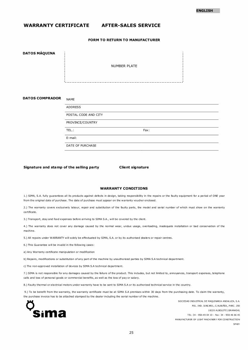
WARRANTY CERTIFICATE AFTER-SALES SERVICE
FORM TO RETURN TO MANUFACTURER
NUMBER PLATE
NAME
ADDRESS
POSTAL CODE AND CITY
PROVINCE/COUNTRY
TEL.: Fax:
E-mail:
DATE OF PURCHASE
Signature and stamp of the selling party Client signature
WARRANTY CONDITIONS
1.) SIMA, S.A. fully guarantees all its products against defects in design, taking responsibility in the repairs or the faulty equipment for a period of ONE year
from the original date of purchase. The date of purchase must appear on the warranty voucher enclosed.
2.) The warranty covers exclusively labour, repair and substitution of the faulty parts, the model and serial number of which must show on the warranty
certificate.
3.) Transport, stay and food expenses before arriving to SIMA S.A., will be covered by the client.
4.) The warranty does not cover any damage caused by the normal wear, undue usage, overloading, inadequate installation or bad conservation of the
machine.
5.) All repairs under WARRANTY will solely be effectuated by SIMA, S.A. or by its authorised dealers or repair centres.
6.) This Guarantee will be invalid in the following cases:
a) Any Warranty certificate manipulation or modification
b) Repairs, modifications or substitution of any part of the machine by unauthorized parties by SIMA S.A technical department.
c) The non-approved installation of devices by SIMA S.A technical department.
7.) SIMA is not responsible for any damages caused by the failure of the product. This includes, but not limited to, annoyances, transport expenses, telephone
calls and loss of personal goods or commercial benefits, as well as the loss of pay or salary.
8.) Faulty thermal or electrical motors under warranty have to be sent to SIMA S.A or its authorized technical service in the country.
9.) To be benefit from the warranty, the warranty certificate must be at SIMA S.A premises within 30 days from the purchasing date. To claim the warranty,
the purchase invoice has to be attached stamped by the dealer including the serial number of the machine.
DATOS COMPRADOR
DATOS MÁQUINA
SOCIEDAD INDUSTRIAL DE MAQUINARIA ANDALUZA, S.A.
POL. IND. JUNCARIL, C/ALBUÑOL, PARC. 250
18220 ALBOLOTE (GRANADA)
TEL: 34 - 958-49 04 10 – Fax: 34 - 958-46 66 45
MANUFACTURER OF LIGHT MACHINERY FOR CONSTRUCTION
SPAIN

26
ENGLISH

27
ENGLISH
SOCIEDAD INDUSTRIAL DE MAQUINARIA ANDALUZA, S.A.
POL. IND. JUNCARIL, C/ALBUÑOL, PARC. 250
18220 ALBOLOTE (GRANADA)
Telf.: 34 - 958-49 04 10 – Fax: 34 - 958-46 66 45
FABRICACIÓN DE MAQUINARIA PARA LA CONSTRUCCIÓN
ESPAÑA