tree root morphology mapping by non-invasive ground-penetrating radar · 2009-04-16 · step 3:...
TRANSCRIPT
Tree Root Morphology Mapping
by
Non-Invasive Ground-Penetrating Radar

Root Inspection Procedure
Scan over either Bare Surface (soil, grass) or
Covered Surface (brick, concrete, paving, asphalt). Choose an antenna with the right
resolution/depth characteristic.
Scan depths to:
1m (3ft) using 900MHz antenna 3m (9ft) using 400MHz antenna
Reflected Radar Beam from Roots
Cross-Sectional View of Roots
Radar Beam
Smallest Detectable Root Diameter:
1cm (0.4in) with 900MHz antenna 2cm (0.8in) with 400MHz antenna

Objectives
Set GPR scan lines in the area around a tree
Scan with GPR system – either covered (concrete, asphalt,
brick, pavers) or bare surfaces – to detect root reflections
Connect the reflections (“hits”) found on each scan line
with succeeding scan lines to create a 3D Root Morphology
Map
Create a Root Surface Density Map to show Root layout
and density
Here are the steps
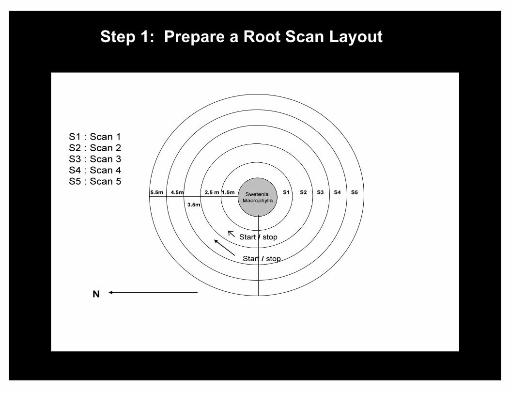
Step 1: Prepare a Root Scan Layout

Step 2: Create a Rough Grid to Implement
the Root Scan Layout
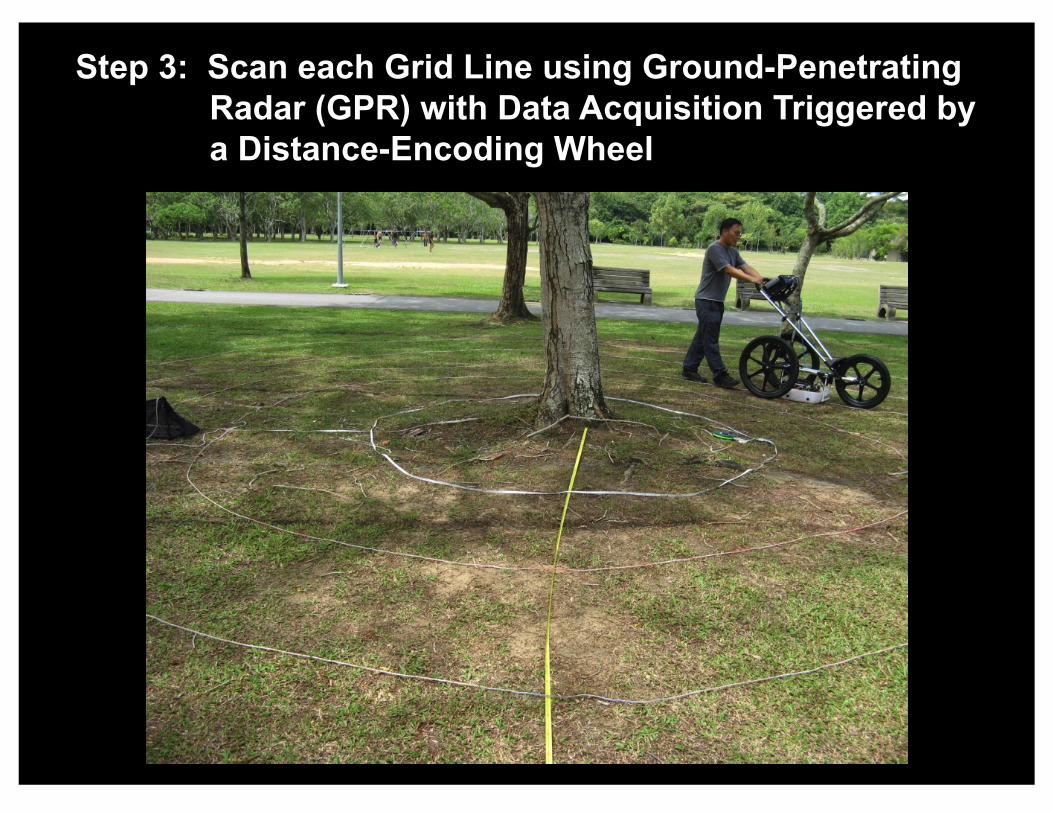
Step 3: Scan each Grid Line using Ground-Penetrating
Radar (GPR) with Data Acquisition Triggered by
a Distance-Encoding Wheel

Step 4: Process each Scan Line to create a 2D “Virtual
Trench” map showing X (distance along scan line) &
Y (depth) coordinates of each Root Detection (dots)

Step 5: Create a 3D Root Morphology map (“Virtual
Excavation”) by algorithmically connecting the
detected roots found on each Scan Line
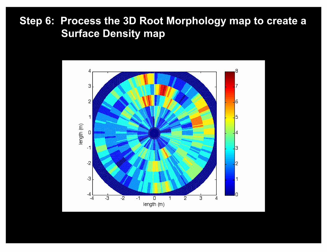
Step 6: Process the 3D Root Morphology map to create a
Surface Density map
Summary