traverse tables with an introductory chapter on co
TRANSCRIPT

i
:

LIBRARYOF THF.
UNIVERSITY OF CALIFORNIA,GIFT OF"
Jl
Accession No. 836.9-U-.
>\0vta{/yvv<
Received ,190


J

TRAVERSE TABLESWITH AN INTEODUCTOEY CHAPTEE ON
CO-ORDINATE SURVEYING
BY
HENEY LOUIS, M.A, A.E.S.M., F.I.C., F.G.S., ETC.i\
PROFESSOR OF MIXING AND LECTURES ON SURVEYING, DURHAM COLLEGE
OF SCIENCE, NEWCASTLE-ON-TYNE
EXAMINER IN MINE SURVEYING TO THK CITY AND GUILDS OF LONDON INSTITUTE
AND
GEOKGE WILLIAM CAUNT, M.A.LECTURER IN MATHEMATICS, DURHAM COLLEGE OF SCIENCE, NEWCASTLE-ON-TVNE
LONDON
EDWAED ARNOLD37 BEDFORD STREET. STRAND
1901

a

PKEFACE.
THE publication of this little work is due to the writer's
conviction, gained in many years of miscellaneous surveying
practice, as well as in some spent in the teaching of surveying,
that the co-ordinate method of plotting traverses is far preferable
to any other, on the score of both accuracy and expedition. There
are, of course, several traverse tables already in existence;but
whilst some of these are calculated with a degree of accuracy
greater than is required in ordinary surveying, and more
especially in ordinary mine surveying, others are not accurate
enough, inasmuch as their calculations are not extended to
every minute of the degree. The price of the former works is,
moreover, somewhat prohibitive, at any rate as far as the
ordinary mine surveyor is concerned.
At the present day it is usual to employ, in ordinary under-
ground and surface work, instruments divided into single
minutes, so that the tables must be calculated for this unit to be
of any real use. In ordinary chaining it may be taken that it
is rare for any traverse to exceed ten chains in length, whilst the
limit of accuracy for such lengths is about one link. The tables
are therefore calculated to five significant places (four places of
decimals), so that their accuracy is about ten times as great
as is attained in ordinary actual work. This limit is therefore
sufficiently near for all practical purposes, and, at the same time,
does not involve any undue amount of arithmetical work.

iv PREFACE.
These tables are not intended for cadastral surveys, for which
seven decimal places are required, or at times even more. The
arrangement of the tables is one which the writer finds in
practice to be convenient for rapid work, all the figures needed
for any given angle being found at one opening of the pages and
in one line. The tables have been entirely recalculated byMr. Gaunt, and checked in all possible ways, and every
precaution has been taken to ensure accuracy in printing, so
as to warrant the hope that they may be found free from
error. The writer ventures to hope that their publication mayserve to popularize this most convenient method of working out
traverse surveys in this country,
HENEY LOUIS.
NEWCASTLE-ON-TYNE,December, 1900,

TBAVEESE TABLES.
CO-ORDINATE SURVEYING.
CO-ORDINATE surveying, or, to speak more precisely, co-ordinate
plotting, is the name given to a method of recording the results
of traverse surveys in which the draughtsman represents each
draft of the survey by means of its rectangular co-ordinates.
It cannot well be applied to any other than traverse surveying,
hence its utility is mainly restricted to such forms of survey work
as depend upon traverses, that is to say, mine surveys, surveys of
roads, rivers, or railways, and surveys of areas. In a traverse
survey the lengths and directions of the various traverses or
drafts are determined in the field by methods with which all
surveyors are familiar; it need only be here observed that,
however determined, the direction of any traverse is the angle
which it makes with any determinate direction;the latter may
either be an absolutely fixed direction, such as the terrestrial
meridian, or it may be comparatively fixed, as the magnetic meri-
dian, or it may be purely arbitrary, such as the direction of the
first draft of the survey, or of any other traverse, or of one of
the main directions in which the survey extends, e.g. the main
road of a large colliery, the principal street of a town, etc. In
mining surveys it is customary in this country to refer all
directions to the magnetic meridian, in spite of several obvious
inconveniences to which this practice is subject; although it
is certainly better to use the terrestrial meridian, yet the
method of plotting by co-ordinates is exactly the same whatever
a 2

vi TRAVERSE TABLES.
be the line of reference that is used. For the sake of sim-
plicity it will here be supposed that a method of surveying
has been adopted by which the angle which each traverse
makes with the terrestrial meridian can be accurately deter-
mined.
Thus, in Fig. 1, let the traverse line of length OA (= I)
make an angle a with the meridian line YY' through 0, and
let XX' be drawn at right
angles to TOY'. Draw Aaand Aa' perpendicular respec-
tively to the lines XX' and
YY' ; then Aa = Oa' = I cos a,
and Aa' = Oa = I sin a, are**f
""
the co-ordinates of the point Areferred to its origin 0, or the
co-ordinates of the traverse OA.
Oa', the meridian co-ordinate,*' is usually spoken of as the
difference of latitude (generally
abbreviated into latitude), and Oa, the equatorial co-ordinate, is
generally called the departure of the traverse OA, and these
words, latitude and departure, are adhered to even when the
reference lines, YY' and XX',do not correspond with either
the terrestrial or the magnetic meridian and equator respec-
tively. It is obvious that the co-ordinates of any traverse can
be calculated by the aid of a table of sines and cosines, but
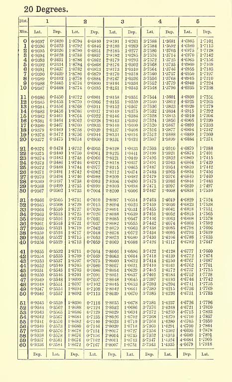
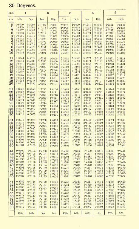
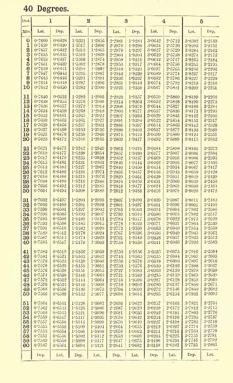
this is a laborious and slow operation. Traverse tables are
merely tables in which the results of these calculations are
recorded so as to save time; in the present traverse tables the
latitude and departure are given for every minute of angle and
for all lengths from 1 to 10, so that the co-ordinates for anydesired length can be taken out by simple addition, at the same
time moving the decimal point as may be required. Thus,
required the co-ordinates of a traverse 1638 links long, makingan angle of 27 49' with the meridian line. Entering the table
headed 27, the minutes are found in the column at the left
hand (headed Min.), and looking horizontally along the line
corresponding to 49', the several figures are taken out under the
unit distances (Dist.) which head each double column of lati-
tude (Lat.) and departure (Dep.), thus

TRAVERSE TABLES. vii
27 ,49'Dist. Lat. Dep.
1000 884-5 466-6
600 530-7 280-0
30 26-5 14-0
8 7-1 3-7
1638 1448-8 764'3
So that the required latitude is 1449 links, and the required
departure 764 links. It will be noticed that the figures are
only taken out to the first decimal place ;in ordinary surveying
fractions of links are not recognized, so that the co-ordinates are
merely required to be correct to the nearest unit;
there is
therefore no object in using more than one decimal place.
Whenever the angle given exceeds 45, the angle must be
sought for at the bottom right-hand corner, and the minutes
read upwards in the last right-hand column; care must be
taken also to read the latitudes and departures upwards in
accordance with the respective designations at the bottom of
the page. In this connection it is worth remembering that
when the angle is less than 45, latitudes are greater than
departures, and when the angle exceeds 45, latitudes are less
than departures, A useful check is also obtained by notingthat
(Distance)2 = (Latitude)
2 + (Departure)2
When one traverse only has to be plotted, but little is gained
by the use of co-ordinates;but when a number of successive
traverses have to be laid down, as is the case in an ordinarytraverse survey, the advantage is evident, as the various latitudes
and departures can be added together arithmetically, and thus
the exact position of the end point determined before the surveyis plotted. Thus, let OA, AB, and BC (Fig. 2) be three traverses,
of which the lengths and the angles which they make with the
meridian are known. Then Oa' and Oa are, as before, the
co-ordinates of the traverse OA or of the point A referred to
its origin ; similarly, J93/ and AM are the co-ordinates of Breferred to its origin A. But Ob = Oa + ab = Oa -J- AM, andOb' = Oa' -f- a'V = Oa' -f MB; therefore the co-ordinates of
the point B referred to the origin are the sums of the re-
spective latitudes and departures of the two traverses OA andAB. In the same way Oc and Oc', the co-ordinates of the point

Vlll TRAVERSE TABLES.
C referred to the origin 0, are the sums of the co-ordinates OA,AB, and BC, it being noted that BG runs in the oppositedirection to OA and AB
}and its latitude is therefore negative.
In other words, the meridian and equatorial co-ordinates of anypoint that is reached by a series of traverses, are the algebraicalsums of the respective latitudes and departures of each one of
the component traverses. It is usual to treat the directions
OJC and OY as positive, and OX' and OY' as negative; in other
words, northerly latitudes and easterly departures are treated
as + quantities, and southerly latitudes and westerly departuresas quantities.
In loose-needle surveys either meridian or quadrant angles
may be read at the will of the surveyor. In ordinary theodolite
surveys and in "racking
"or
"fixed-needle
"surveys with the
Vernier dial, the angles are determined that any given traverse
makes with the meridian (or other arbitrary direction), so that
any angle may be registered from to 360. The fii'st step is
therefore to reduce these meridian angles (or azimuths, as theyare often called) to quadrant angles by the following rules :
If the meridian angle is letween and 90, the quadrant is
N.E., and the quadrant angle = meridian angle.

J. V J^JTVOJ.
TRAVERSE TABLES. ix
If the, meridian angle is between 90 and 180, the quadrantis S.K, and the quadrant angle = 180 meridian angle.
If the meridian angle is between 180 and 270, the quadrant
angle is S. W., and the quadrant angle = meridian angle 180.
If the meridian angle is between 270 and 360, the quadrantis N. W., and the quadrant angle = 360 meridian angle.
For example, to find the quadrant angles corresponding to
the following meridian angles : (a) 17 23'; (6) 141 44'
; (c) 250
21'; (d) 339, 08'.
Meridian angle. Quadrant angle.
(a) 17 23' N. 1723'E.(6) 141 44' S. (180
- 141 44') E. = S. 38 16' E.
(c) 250 21' S. (250 21' - 180) W. = S. 70 21' W. ,
(d) 339 08' N. (360- 339 08') W. = N. 20 52' W.
Sometimes these angles are simply written +17 23'+ ,
-38 16'+, -70 21'-, +20 52'-, this method being
specially convenient when any arbitrary line is selected as the
direction of reference in preference to a meridian;
it is under-
FIG. 3.
stood that the first sign always refers to the latitude and the
last to the departure.
The successive stages in working out a traverse survey byco-ordinates, preparatory to plotting, are best illustrated by an
example. Let Fig. 3 represent a traverse survey of an area

x TRAVERSE TABLES.
bounded by straight lines, executed by the " double fore-sight"
method with an ordinary theodolite, the area forming a seven-
sided polygon. The first two columns (see p. xii), namely the
measured lengths of the sides and the observed theodolite
readings, are obtained in the field and taken from the field-book
in which they were entered.1 At the beginning of the surveythe theodolite is supposed to be pointed due north; the first
reading gives therefore the meridian bearing of the first traverse
OA; the meridian bearings, or azimuths, of the subsequenttraverses are obtained by the well-known rule : Add the
observed theodolite reading to the last meridian bearing and
subtract 180 from, or add 180 to, the sum, according as that
sum is greater or less than 180. The result in this ca.se is as
follows :
Meridian bearing of OA 295 12'
Theodolite reading of AB 72 13'
367 25'
180
Meridian bearing of AB 187 25'
Theodolite reading of BC 135 37'
323 02'
180
Meridian bearing of B C 143 02'
Theodolite reading of CD 87 20'
230 28'
180
Meridian bearing of CD 50 28'
Theodolite reading of DE 240 05'
290 33'
180
Meridian bearing of DE 110 33'
Theodolite reading of EF 41 26'
151 59'
180
Meridian bearing of EF 331 59'
Theodolite reading of FO 79 10'
411 09'
180
Meridian bearing of FO 231 09'
The meridian bearings thus obtained are entered in their
1 It goes without saying that the closing angle at 0, which in this case
should be equal to 244 03', is observed and noted in the field-book as a
check, though it is not required for these calculations.

TRAVERSE TABLES. xi
proper column, and then the column of quadrant bearings is
at once filled in (see p. xii), in accordance with the rules already
given. By reference to the tables, the latitudes and departures
are then determined by simple addition ;the first two may be
given in full by way of example :
64 48'DUt. Lat. Dep.
1000 425-78 904-83
400 170-31 361-93
8 3-41 7-24
1408 599-5 1274-0
7 25'
800 793-31 103-27
40 39-67 5-16
7 6-94 0-90
847 839-9 109-3
The latitudes and departures are entered in their re-
spective columns. As this is a closed survey, returning to
the starting point 0, the total north and south latitudes and the
total east and west departures ought to be respectively equalto each other, and it will be seen that such is practically the
case, fractions of a link being disregarded.
The last two columns, headed total latitudes and departures,
are really the successive co-ordinates of each of the surveystations
; they are obtained by the successive algebraical
additions of the latitudes and departures respectively, the sumor difference taking the same sign as the larger of the two
figures. Thus, to take the latitudes, the latitude of the pointA is evidently 599*5 links N; then we have :
Latitude of point B = 599'5 N. + 839-9 S. = (839-9-
599-5) S. = 240-4 S.
Latitude of point C = 240'4 S. + 1428*6 S. = 1669*0 S.
Latitude of point D = 1669-0 S.+ 1059-2 N. = (1669-0-
1059-2) S. = 609'8 S.
Latitude of point E = 609-8 S + 347-9 S. = 957-7 S.
Latitude of point F = 957-7 S. + 1743-6 N. = (1743-6-
957-7) N.= 785-9 N.Latitude of point = 785'9 N. + 786-0 S. = (786-0
-785-9) S. = 0-1 S.
The total departures are calculated in precisely the same
way. The clerical work of the addition is checked by adding
up the two columns of latitude and the two of departure ;the
differences between these respective pairs should be equal to the
final total latitudes and departures.

Xll TRAVERSE TABLES.
s3
OAABBCCDDEEFFO

TRAVERSE TABLES. xiii
the irregular expansion and contraction of even the best draw-
ing paper1is more than enough to introduce grave inaccuracies
into the best drawn plan.
As an example of the method of calculation, let it be
required to determine the distance and bearing of station Efrom station B.
From the column of total latitudes and departures we have
Station B. Lat. S. 240-4. Dep. W. 1383-3
Station E. Lat. S. 957-7. Dep. E. 1903-2
Therefore E is 717-3 links S. and 3286'5 links E. of B.
Bearing of line BE = S. tan-1
-~j E. = S. 77 41' 15" E.
Distance EB = . = .
*ep'. = */tep* + lat.* =
'
. . . * .,cos bearing sin bearing cos 77 41 15
sn + 3286-5* = 3364 links
These calculations are best made in the usual way by the
aid of tables of logarithms. In case of need, the traverse tables
can be used for them, as the departure column for distance
= 1, is practically a table of natural sines, whilst the corre-
sponding latitude column is practically a table of natural
cosines, and these evidently give all the elements required for
the calculation. In ordinary practice it is, however, far better
to use any good table of logarithms for this portion of the work.
The above survey is an imaginary one, and there is therefore
no closing error. In actual closed traverse surveys there is
of course usually some error. By working out the co-ordinates,
and by adding up the observed angles (including the closing
angle), it is at once obvious whether the error is in the linear
or in the angular measurements;in the latter case, if it is only
the closing angle that has been read wrong, the co-ordinates
will close, though the angles do not. If the error falls within
the required limits of accuracy, it is easily distributed between
the co-ordinates, and the plotting is done from the co-ordinates
thus rectified.
The following is an example from actual practice, of a surveyin a coal mine. A survey was started from a peg in the "
flat,"
1 Those interested in this matter should consult an important paper byMr. C. C. Leach. Transactions of the North of England Institute of MiningEngineers, Vol. xxxiv., 1884-85, p. 175.
I

XIV TRAVERSE TABLES.
and was extended to a point in a " back place"
to which it was
desired to drive a road from the peg in the flat. The theodolite
was set up in the flat, using the centre line of the flat as the axis
of direction to which the survey was to be referred. A copyof the field-book is given below, many of the minor details
being, however, omitted.
=

TRAVERSE TABLES. xv
The co-ordinates are worked out as previously explained,
and the total latitudes and departures obtained as follows :

XVI TRAVERSE TABLES.
becomes one of quite secondary importance. All that is
required to be known is already determined before the plottingis commenced. It may also be remarked that all the opera-
tions up to and including the taking out of the total latitudes
and departures are of the utmost simplicity, involving no higher
Scede % inch-1 Chcdrv
FIG. 4.
arithmetical knowledge than the addition and subtraction of
decimals, and may hence be entrusted to any moderately
intelligent lad, instead of occupying the time of the surveyor
himself.
The advantages of the use of co-ordinates are, however,

TRAVERSE TABLES. xvn
most evident when it is necessary to determine the area in-
cluded in a closed traverse. Unless co-ordinates are used the
only method of determining such areas accurately is by an
involved trigonometrical method, consisting of cutting the area upinto triangles the apices of which meet in any assumed point.
The angles of each triangle have then to be calculated, the
triangles solved, and the sum of their areas thus determined.
This method is so laborious that it is never used in practice.
Unless this or the method of co-ordinates is used, however, the
determination of the area can only be made by first plotting the
survey, by which a number of errors of more or less importanceare necessarily introduced.
By the use of co-ordinates, all these difficulties are avoided,
and the area of any closed traverse can be calculated directlyand easily from its latitudes and departures, without anyplotting at all. The principle of the calculation is best seenfrom a simple example :
Let the five sided figure OABCD (Fig. 5) be the plan of
a traverse survey situated wholly on one side of the meridian
through the point 0, and let it be required to determine thearea of the figure. The total latitudes and departures are calcu-
lated in the usual manner, and we have for the respective surveystations :

xviii TRAVERSE TABLES.
Total latitude. Total departure.00A Oa'( = -y) Oa( = 'x)
B Ob'( = -yi) Ob( = *:)
C Oc'( = ya) Oc( = x,}D Od'( = #3) Od( = a?8)
Then the area of the figure
OABCD = d'DCSAa' - d'DO - OAa'd'DCBAa' = d'DCc' + c'CBV + VBAu'
d'DCc' = UDd' + Cc'}d'c'
= H+0)(-y-0)Hence
= J[(0 + 3)(0-
2/3) + (aJ3 + a;a)
/(dep. of + dep. of D)(lat. of - lat. of D)(dep. of D 4- dep. of (7)(lat. of 7) - lat. of (7)
/. the area OABCD = J ( (dep. of (7 + dep. of 5) (lat. of C' - lat. of 5)(dep. of 5 + dep. of -4)(lat. of B - lat. of A)((dep. of A + dep. of 0)(lat. of A - lat. of 0)
The rule for the calculation of the area contained by a closed
traverse is therefore as follows :
The algebraic sum of the total departures of each pair of
adjacent angular stations is multiplied by the algebraic difference
of their total latitudes ; the products thus obtained are added
together, and the sum divided by two gives the area required.
In applying this rule it must be borne in mind that the
station points must always be taken in strict order.1 To each
total latitude or departure the correct algebraic sign must be
prefixed, and regard must be had to it in the arithmetical
1 It makes no difference whether the points be taken in the order in
which they have been surveyed, or in the opposite order; the essential pointis that one regular order shall be adhered to. If the points are taken in the
opposite order the only difference will be that the area will have a instead
of a 4- sign. This is easily seen; for in the above calculation if the pointsbe taken in the opposite order, the signs of the sums of the departures will be
unaltered, and the signs of the differences of latitudes will be changed (e.g.
(y2 ?/3) instead of (y3 y2)> etc.), so that the sign of the area will be
changed, its numerical value being unaffected. The sign obtained for the
area of any closed traverse depends upon the direction of the first traverse,and upon that in which the points are taken
;it is always considered as
positive.

TRAVERSE TABLES. xix
operations involved. The result will be expressed in squares
of the unit of measurement employed, square links if the surveywas made in links, square feet or square metres if the distances
were measured in feet or metres, etc.
The above rule is occasionally stated in a different way,which is sometimes more convenient for calculation.
The total latitude of each station is multiplied by the
algebraic sum of the departure of that traverse, and of the one next
following ;1 the sum of the products thus obtained, divided by 2,
gives the area required.
The departure here referred to is not the total departure
referred to the origin of the survey, but the departure of the
traverse referred to its own starting station. It can easily be
shown that these two rules are practically the same.
For in Fig. 5, taking the values given above, we shall have
for the departures of each traverse
Departure of point D referred to OC1 7)*'
>"^ ^
^Then according to the second rule
Twice area OABCD =
xl- x.2
X Xl
-x
Again, according to the first rule, we have seen that
Twice area OABCD =*s
-s/3 - + 0*3 + s2)(ys
-2/2) + (a?2 + i)(y
- XIJ\ + Xl*J
the same result as that given by the second rule.
All that has been said of the first rule holds equally goodof the second. In both of them the words latitude and
departure may also be interchanged without altering the result,
so that there are really four different arithmetical operationsthat can be employed indifferently.
Yet another method is sometimes employed, known as that of
the" double meridian distance." In this the successive latitudes
are multiplied by multipliers obtained from the departures ;a
1 It is evident that the suras of the departures of any two traverses is
equal to difference between the total departures of the point before and the
point after the one being worked.

XX TRAVERSE TABLES.
column of" double departures
"is formed by adding each
departure to the preceding one;from these double departures
the multipliers are obtained by adding each double departureto the last multiplier, the first multiplier being always zero.
By way of example, the area of the figure OABCD may be
calculated, the values of the departures and latitudes being as
follows :

TRAVERSE TABLES. xxi
In both cases the results are of course identical, namely 49,910
square links or 0*4991 acre. It will be seen that the second
method of calculation here produces a negative sign ;this would
have been positive had the points been taken in the oppositeorder.
The following is an example of the application of the second
rule to the same area :
Total latitudes.

XX11 TRAVERSE TABLES.
Latitude.

TRAVERSE TABLES. xxin
Stations.

XXIV TRAVERSE TABLES.
to select the traverse lines so as to equalize as nearly as possible
the offset areas on either side;this has to be done by inspection,
on the ground, and of course requires a good deal of practice.
It occasionally happens that some of the points in a surveyare determined by methods of triangulation instead of bytraversing. Broadly speaking, the term triangulation may be
applied to the determination of any point by angular measure-
ments from, the two ends of a base-line of known length ;the
triangle is then solved, and the lengths of the two unknownsides calculated. This calculation is simply and easily per-
formed by means of co-ordinates.
The problem in its most general form is shown in Fig. 7.
Suppose the points A,B have been already determined, their
CL'
Y'FIG. 7.
departures Oa and 01 being x and ^ and their latitudes Oa'
and Ob' being y and ^ respectively. The angles AC(= a)and ABC( = &) are determined by observation
;from these data
the latitude and departure of have to be calculated. Letthe quadrant bearing of the line BA be N". a E.
; then the
quadrant bearing (]3) of the line EC = 1ST. (a + 6) E., and the
quadrant bearing (y) of the line A C = S. (a a) E. Care mustbe taken in every case that the signs are correct according to
the particular quadrant.
Then tan 7=-^-=a'c' y -
tan * ~
-b'c Oc' yl
Whence Oc' = * tan ? + x
tan 7 + tan y8

TRAVERSE TABLES. xxv
The departure Oc may be calculated from the corresponding
formula :
QC_ *i cot & + V + x cot 7 yt
cot /3 + cot 7
The above is the method generally employed, and is perhapsthe most convenient when the ordinary mathematical tables are
available. It is, however, possible to use a method to which
the traverse tables can be applied, and the work thus consider-
ably simplified. For in Fig. 7
Oc = Oa + ac = x + OK
... Qc = xsin (a + b)
which may be written
n AB sin b . 10 sin y10 sin (a + b)
All these values can now be taken from the traverse tables
because
AB sin b is the departure of distance AB for the angle b
10 sin 7 is the departure of distance 10 for the angle 710 sin (a 4- &) is the departure of distance 10 for the angle a -f Z>; if
a + b is greater than 90, the angle 180 (a + b) should be used instead.
Another form for the above expression is
n ,AB sin a . sin
:a?1+*in(a + b)
For the latitude Oc', either of the two following expressions
may be used:
^ , ,AB sin a . cos fl
1
sin (a + i)
s^n ^ C08
sin (a + b)
Any of these may be used with the traverse table as above
indicated, by multiplying numerator and denominator by 10,
or by any other convenient number so that in the last case the
second term of the formula for Oc would read
(dep of AB for angle &) x (lat. of 10 for angle 7)
dep. of 10 for angle (a + 6)
As an example of these calculations let the co-ordinates of
the two points A,B of a traverse survey be as follows :

XXVI TRAVERSE TABLES.
Lat. ofJ. ... N. 87 links Dep. of^L ... W. 204 links
Lat. of ... S. 85 Dep. of B ... E. 89
Quadrant bearing of AB = S. 59 35' E. Length of AB - 340 links.
From A and B, Fig. 8, the angles between the direction ABand the lines joining these points with the two points C and D,
Scale inch,<-1 Chain.
which it is desired to fix, have been observed, and found to be
as follows :
Angle CAB = 40 28'
= 69 13'Angle ABC = 68 59'
Angle ABD = 38 05'
Then, to determine the point C, we have by the first method
Meridian bearing of AC = 180 00' - 59 35' - 40 28' = 79 57'
Quadrant bearing ofAC = N. 79 57' E.
Meridian bearing of BC = 360 00' - 59 35' + G8 59' = 369 24'
Quadrant bearing of BC = N. 9 24' E.
T} , (87 x tan 79 57') + (85 x tan 9 24') + 89 + 204
tan 79 57' - tan 9 24'
= N. 146
And Oc = (2Q4 x cot 79 57') + (89 x cot 9 24') + 87 + 85
= E. 127
cot 9 24'^- cot 79 57'
As a check upon the arithmetical work of the calculations
we have
Tan 9 24' = I27n
"" 89 = 0-1 G514G + 85
To determine the point D, we have

TRAVERSE TABLES. xxvii
Meridian bearing of AD = 180 - 59 35' + 69 13' = 189 38'
Quadrant bearing of AD = S. 9 38' W.Meridian bearing of BD = 360 - 59 35' - 38 05' = 262 20'
Quadrant bearing of BD = S. 82 20' W.
T , n r _ (87 x tan 9 38') + (85 x tan 82 20') + 204 + 89
tan 82 20' - tan 9 38'
= S. 129
.
d, = (204 x cot 9 38') + (89 cot 82 20
?
) + 87 + 85
cot 9 38' cot 82 20'
= W. 240
In applying these formulas special attention must be paid
to the signs of the departures and latitudes.
Using now the second method given above
O -201 + (34 ' sin 68 59/)(10 sin 79 57/)
10 sin (68 59' + 40 28')
From the tables
Departure of 300 = 280-04 for angle G8 59'
Departure of _40= 37-34
Departure of 340 = 317-38
Departure of 10 for angle 79 57' = 9'8466
Departure of 10 for angle 109 27' = departure for angle 70 33' = 9-4293
= -204 + 331-4 = +127-4
, = 87 , (340 . sin 68 59') x (10 cos 79 57')
10 sin (68 59' + 40 28')
From the tables
Latitude of 10 for angle 79 57' = 1-7451
, .7
317-38 x 1-7451
9-4293
= 87 + 58-7 = +145-7
Od = -904 - (34 sin 38 05') x (10 . sin 9 38')
10. sin (69 13' + 38 05')
9fu _ 209-71 x 1-6734
9-5476
= -(204 + 36-7) = -240-7
Od' = 87 (340 . sin 38 05') x (10 . cos 9 38')
10 . sin (69 13' + 38 O5'j~~209-71 x 9-859
9-5476
= 87-216-5 = -129-5
UNIVERSITY
CALIF01

xxviii TRAVERSE TABLES.
The results obtained are of course practically the same if
the calculations are made with a sufficient degree of accuracy,
but the use of the traverse tables even in such triangulation
problems is seen to very much shorten the calculations.

TRAVERSE TABLES.

Degrees.
Dist.

e

1 Degree.
Dist.

6

2 Degrees.
Dist.

8

3 Degrees.
Dist.

6

4 Degrees.
Dis

t

5 Degrees.
Dist.

6

6 Degrees.
Dist


7 Degrees,
Dist

6

8 Degrees.
Dist

6

9 Degrees.
Dist.

e

10 Degrees.Dist

e

11 Degrees.
Dist.

e

12 Degrees.
Dist.


13 Degrees.
Dist.

6

14 Degrees.
Dist.

e

15 Degrees.
Dist.

e

16 Degrees.Dist

(

17 Degrees.
Dist.

6

18 Degrees.
Dist.

6

19 Degrees.Dist.

6
20 Degrees.Dist.

6

21 Degrees.Dist.

6

22 Degrees.
Dist.


23 Degrees.
Dist.

6

24 Degrees.Dist

6

25 Degrees.
Dist

6

26 Degrees.
Diet.

I UNIVERSITY I
Vog . -*\*-S

27 Degrees.
Dist

6

28 Degrees.
Dist.

6

29 DegreesDist.

6
30 Degrees.
Dist,

(

31 Degrees.
Dist.

6

32 Degrees.
Dist.

6

33 Degrees.
Dist.

6

34 Degrees.
Dist.

6

35 Degrees.
Dis

6

36 Degrees.
Dis

(

37 Degrees.Dist.

6

38 Degrees.
Dist.

6

39 Degrees.Dist.

6
40 Degrees.
L>i*t.

6

41 Degrees.
Dist.

6

42 Degrees.
Dist.

6

43 Degrees.
Dist


44 Degrees.Di&t.

(

THE PRINCIPLES OFLANDED ESTATE MANAGEMENT.
By HENRY HERBERT SMITH,
Fellow of the Institution of Surveyors^
Agent to the Marquess of Lansdowtie, K.G., the Earl of Crewe, Major* General the
Lord Mcthuen, Major Hippisley (Scots Greys], and other landed proprietors.
Illustrated with Plans. Demy 8vo. Cloth, i6s.
STANDARD. "In this most useful and interesting book Mr. Smith has compressed into
little more than three hundred pages as much practical information and sound advice as
many writers would have spread over three volumes. We can confidently recommend the
volume to all persons either directly or indirectly connected with the important subjectof which it treats."
AN EXPERIMENTAL COURSE OFCHEMISTRY FOR AGRICULTURAL STUDENTS.
By T. S. DYMOND, F.I.C.,
Lecturer on Agricultural Chemistry in the County Technical Laboratories, Chelmsford.
192 pages, with 50 Illustrations. Crown 8vo. Cloth, 2s. 6d.
ELECTRICAL TRACTION.By ERNEST WILSON, M.I.E.E.,
Professor of Electrical Engineering at King's College, London.
viii + 253 pages, with 81 Illustrations. Crown 8vo. Cloth, 5*.
AN ELEMENTARY TREATISE ON PRACTICALMATHEMATICS.
By JOHN GRAHAM, B.A., B.E.,
Lectiirer on Applied Mathematics in the Technical College, Finsbury.
viii + 276 pages. With Answers and numerous Diagrams. Crown 8vo. Cloth, ^s. 6d.
CALCULUS FOR ENGINEERS.By JOHN PERRY, M E.
} D.Sc., F.R.S.,
Professor of Mechanics and Mathematics in the Royal College of Science, London ;
Vice-President of the Physical Society ; Vice-President of the
Institution of Electrical Engineers.
Third Edition, Revised. viii -f- 382 pages, with 106 Illustrations. Crown 8vo.
Cloth, 7s. 6d.
LONDON: EDWARD ARNOLD, 37, BEDFORD STREET, STRAND.


THIS BOOK IS DUE ON THE LAST DATESTAMPED BELOW
AN INITIAL FINE OP 25 CENTSWILL BE ASSESSED FOR FAILURE TO RETURNTHIS BOOK ON THE DATE DUE. THE PENALTYWILL INCREASE TO SO CENTS ON THE FOURTHDAY AND TO $1.OO ON THE SEVENTH DAYOVERDUE.
24 1938
LD 21-95m-7,'37

YC 13553
