traveling solvent floating zone growth technique … solvent floating zone growth technique (tsfz)...
TRANSCRIPT
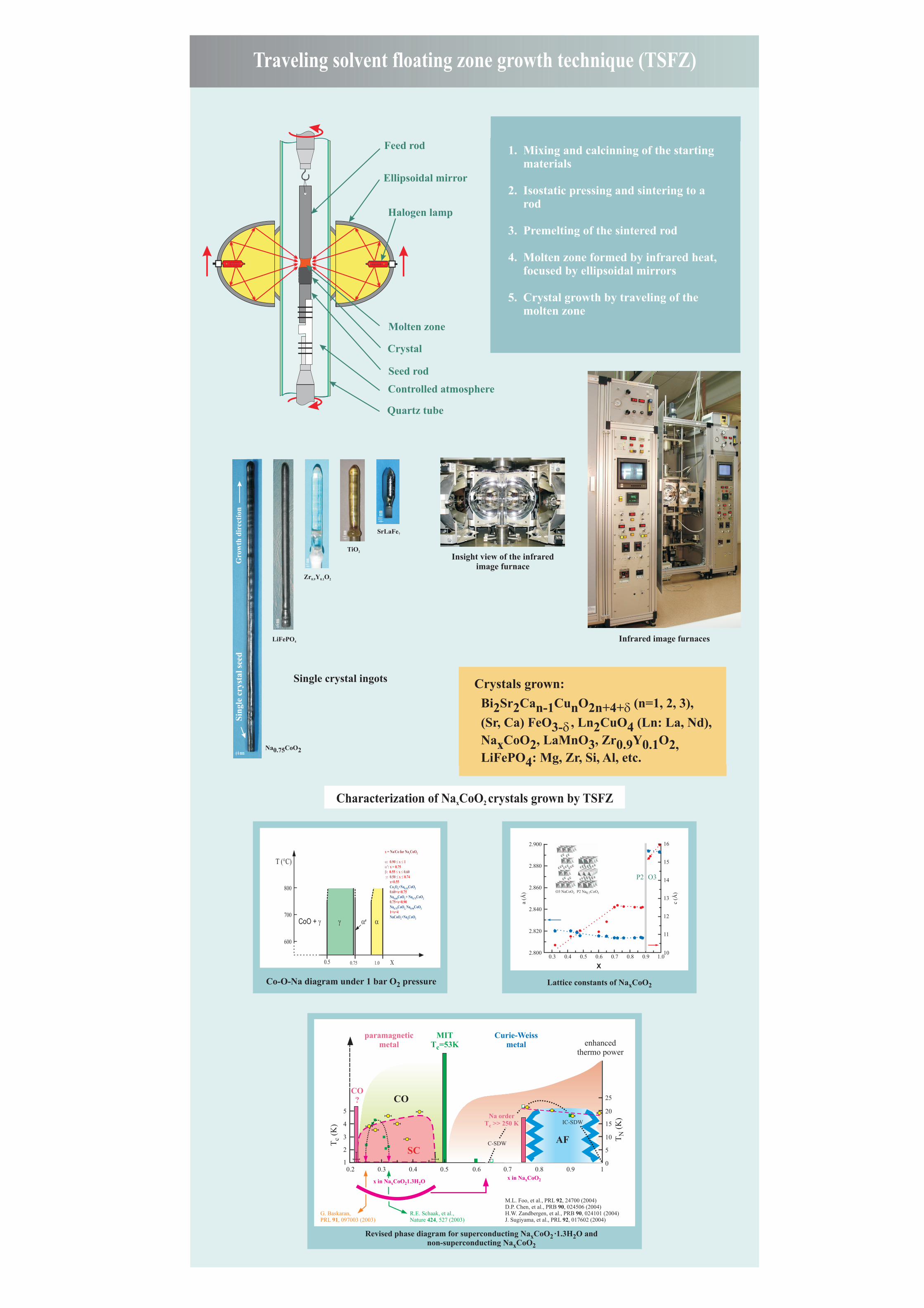
Traveling solvent floating zone growth technique (TSFZ)
1. Mixing and calcinning of the starting materials
2. Isostatic pressing and sintering to a rod
3. Premelting of the sintered rod
4. Molten zone formed by infrared heat, focused by ellipsoidal mirrors
5. Crystal growth by traveling of the molten zone
Insight view of the infraredimage furnace
Feed rod
Molten zone
Ellipsoidal mirror
Halogen lamp
Crystal
Seed rod
Quartz tube
Controlled atmosphere
Lattice constants of Na CoOx 2
0.3 0.4 0.5 0.6 0.7 0.8 0.9 1.0
2.820
2.840
a (Å
)
c (Å
)
2.860O3 NaCoO2 P2 Na CoO20.7
2.880
2.900
2.800 10
11
12
13
14P2 O3
15
16
Co-O-Na diagram under 1 bar O pressure 2
0.75 1.0 X
800
700
600
0.5
T (°C)
Revised phase diagram for superconducting Na CoO ·1.3H O and x 2 2non-superconducting Na CoOx 2
0.6 0.7
x in Na CoOx 2x in Na CoO 1.3H Ox 2 2
0.8 0.9 10
5
T (
K)
N
T (
K)
c 10
15
20
25
0.4
G. Baskaran,PRL 91, 097003 (2003)
R.E. Schaak, et al.,Nature 424, 527 (2003)
M.L. Foo, et al., PRL 92, 24700 (2004)D.P. Chen, et al., PRB 90, 024506 (2004)H.W. Zandbergen, et al., PRB 90, 024101 (2004)J. Sugiyama, et al., PRL 92, 017602 (2004)
paramagneticmetal
Curie-Weissmetal enhanced
thermo power
MITT =53Kc
0.50.3
CO?
0.21
2
3
4
5Na order
T >> 250 Kc
C-SDW
IC-SDW
AFSC
CO
Na CoO0.75 2
LiFePO4
Zr Y O0.9 0.1 2
SrLaFe7
TiO2
Single crystal ingots
Sin
gle
crys
tal
seed
Gro
wth
dir
ecti
on
f 6 mm
f 6 m
m
f 8 m
m
f10 m
m
f 8 m
m
Crystals grown:
Bi Sr Ca Cu O (n=1, 2, 3), 2 2 n-1 n 2n+4+d (Sr, Ca) FeO , Ln CuO (Ln: La, Nd), 3-d2 4 Na CoO , LaMnO , Zr Y Ox 2 3 0.9 0.1 2, LiFePO : Mg, Zr, Si, Al, etc.4
Characterization of Na CoO crystals grown by TSFZx 2
Infrared image furnaces
X