transverse vibration of spinning disk with attached...
TRANSCRIPT

MultiCraft
International Journal of Engineering, Science and Technology
Vol. 1, No. 1, 2009, pp. 74-89
INTERNATIONAL JOURNAL OF
ENGINEERING, SCIENCE AND TECHNOLOGY
www.ijest-ng.com
© 2009 MultiCraft Limited. All rights reserved
Transverse vibration of spinning disk with attached distributed patch and discrete point masses using finite element analysis
Vinayak Ranjan1* and M.K.Ghosh2
1 Department of Mechanical Engineering and Mining Machinery Engineering, Indian School of Mines, Dhanbad, Jharkhand, India
2 Department of Mechanical Engineering, Institute of Technology, Banaras Hindu University,Varanasi, 221005, India *Corresponding author (e-mail: [email protected])
Abstract Free and forced transverse vibration characteristics of a thin spinning disc attached to a rigid core have been investigated by finite element analysis using ANSYS software. The effect of discrete point masses and patches of distributed masses attached at the periphery of the plate on free and forced vibration behavior of a spinning disc has been investigated. Discrete point masses and distributed patch masses have been placed at higher strain regions to look into its influence on the natural frequencies, mode shapes and response of the plate to external excitation. Results for eight and sixteen point masses and patches on the vibration characteristics have been compared. It has been observed that discrete patches and point masses have significant influence on the modal frequencies and these can also act as dynamic vibration absorbers in reducing vibration of a spinning disc. It has also been shown that discrete patches of piezoelectric patches can also be used to actively control vibration of the spinning disc. Keywords: Free and forced vibration, discrete mass and patch, vibration control.
1. Introduction Spinning discs are important components in various mechanical applications such as circular saws, disk brakes, hard disks, optical discs and gas turbines. Vibration control of spinning discs has been studied by a number of researchers. Lamb and Southwell (1922) and Southwell (1922) have reported a study on the free vibration of flexible disks. Eversman and Dodson (1969) studied the free vibration of a centrally clamped spinning disk. Barasch and Chen (1972) investigated on the natural frequencies of rotating disk using modified Adam’s method. Iwan and Moeller (1976) explored the vibration behavior and stability of spinning disks subject to stationary transverse loads. They employed eigenfunction expansion method to calculate the natural frequencies. Chen and Bogy (1992) examined the natural frequencies of rotating discs with stationary load system. They presented a theoretical study of a general gyroscope system and applied it to a spinning disc. Ramaiah (1981) studied the natural frequencies of spinning annular plate for eight different boundary conditions using Rayleigh-Ritz method. Lakshminarayana (1986) analyzed the rotating laminated composite annular disc using finite element method. Sinha (1998a, 1998b) investigated the free vibration problem of a spinning annular disc with uniformly distributed masses or a ring attached to its outer edge by using Rayleigh –Ritz technique. Huang and Yu (1990) examined the vibration behavior of a rotating annular plate with elastic or rigid restraints at discrete locations. They used energy principle and Galerkin method to obtain an approximate solution. Shahbab (1993) analyzed the transverse vibrations of a spinning flexible variable thickness disc. He employed both Ritz method and finite element technique and also carried out experimental investigation. Lee and Ng (1995) determined the natural frequencies and critical speeds of a spinning annular plate of varying thickness based on Lagrangian approach and assumed mode method. Liang et al. (2002) studied the free and forced vibration of a rotating polar orthotropic annual plate with a stationary concentrated transverse load. They used Galerkin approximation to evaluate the eigenvalues of the system and stressed that discs with higher modulus ratios or poison’s ratios have higher natural frequencies. Jen-San Chan (2003) proposed an active control scheme based on the transfer function model to suppress the vibration of a spinning disc. Ferretti et al. (2002) presented a methodology, based on dynamic modeling and experimental measurements to study the vibrations in hard disc drives. Curadelli et al. (2004) dealt with the vibration control of a plate excited by rotary machines by placing masses on the plate system and compared its performance with the conventional

Ranjan and Ghosh / International Journal of Engineering, Science and Technology, Vol. 1, No. 1, 2009, pp. 74-89 75
vibration isolation using springs. Wang (2005) determined the natural frequencies of a circular plate with an attached core for different boundary conditions. Koo (2006) calculated the natural frequency and critical speed for rotating composite disks by the Rayleigh–Ritz method. He showed that the circumferentially-reinforced disk is more effective in increasing critical speed than the radially-reinforced disk. Bauer and Eidel (2007) determined the lower approximate natural frequencies of a spinning circular plate for various boundary conditions. They determined the approximate lower natural frequencies as functions of the speed of spin. Duan et al. (2008) has proposed that fundamental vibration modes of circular plates with free edges can be modified by increasing the bending rigidity of the outer rim of the circular plate by using a larger thickness or by using a material with a larger Young’s modulus or both. Bashmal et al. (2009) studied the in-plane modal characteristics of circular annular disks under combinations of all possible classical boundary conditions. The in-plane free vibration of an elastic and isotropic disk is studied on the basis of the two-dimensional linear plane stress theory of elasticity. The boundary characteristic orthogonal polynomials are employed in the Rayleigh–Ritz method to obtain the natural frequencies and associated mode shapes. In the present work, free and forced transverse vibration behavior of a spinning disc with a rigid core having discrete patches and discrete masses attached at its periphery have been analyzed using finite element method. The actuation effect of piezoelectric patches on the transverse vibration of rotating disc has also been looked into. 2. Theory and formulation The equation of the motion for the free transverse vibration of a rotating thin circular plate in space fixed coordinates is given by Wang (2005):
⎥⎦
⎤⎢⎣
⎡⎟⎠⎞
⎜⎝⎛
∂∂
∂∂
+⎟⎠⎞
⎜⎝⎛
∂∂
∂∂
−∇θ
σθ
σ θ
rw
rwr
rrhwD r4 +
2
2
wht
ρ⎡ ⎤∂⎢ ⎥∂⎣ ⎦
= 0 (1)
Notations used to write the above equation are given below: ),,( trw θ denotes the transverse displacement with respect to ),( θr frame,
ρ is the density of plate, ν is the Poisson’s ratio, Ω is the angular speed of the plate, h is the thickness of the plate,
( )2
3
112 ν−=
EhD is the bending stiffness of the plate
2
2
2
22
24 1
⎟⎟⎠
⎞⎜⎜⎝
⎛
∂∂
+∂∂
+∂∂
≡∇θrrrr
( Ω,rrσ ) ) and are stresses due to centrifugal effect and are given by ( Ω,rθσ
( )Ω,rrσ = ( )222
83 ra −Ω+ ρν + ( ) ( ) ( )[ ]
( ){ } ⎟⎟⎠
⎞⎜⎜⎝
⎛−
++−+−+−Ω 1
1(18131
2
2
22
22222
ra
abbabνν
νννρ
( )Ω,rθσ = ( ) ( )[ ]222
3138
rR ννρ+−+
Ω ( ) ( ) ( )[ ]( ){ } ⎟
⎟⎠
⎞⎜⎜⎝
⎛−
++−+−+−Ω
− 11(18
1312
2
22
22222
ra
abbabνν
νννρ
where,
b is the inner radius of the disk, where core of thickness 0.008 m is attached. a is the outer radius of the disk
The boundary conditions are 0=w ; for (2) br =
0=∂∂
rw ; for (3) br =
⎥⎥⎦
⎤
⎢⎢⎣
⎡⎟⎟⎠
⎞⎜⎜⎝
⎛
∂∂
+∂∂
+∂∂
− 2
2
22
2 11θ
ν urr
urr
wD = 0 ; for ar = (4)

Ranjan and Ghosh / International Journal of Engineering, Science and Technology, Vol. 1, No. 1, 2009, pp. 74-89 76
( ) ( )⎥⎥⎦
⎤
⎢⎢⎣
⎡⎟⎠⎞
⎜⎝⎛
∂∂
∂∂∂−
+∇∂∂
−θθ
ν wrrr
wr
D 11 22 =0 ; for ar = (5)
The fourth order partial differential equation given by (i) has historically been difficult to solve exactly. Finite Element Method has been used as an efficient tool for modeling the vibration response of the plate, wherein a system of equations is constructed which is solved as an eigenvalue/eigenvector problem. ANSYS has been used to determine the mode shapes also called eigenvector and the natural frequencies of the plate system. The mode extraction method employed is Block Lanczos [ANSYS ]. A block shifted Lanczos algorithm as found in Grimes et al. (1994) is the theoretical basis of the eigenvalue solver. The method employs an automated shift strategy to extract the number of eigen value requested. The Block Lanczos method is the variation of the classical Lanczos algorithm where the Lanczos recursions are performed using a block of vectors as opposed to a single vector as explained by Rajakumar and Rogers (1991). The Lagrange Multiplier approach is implemented to treat constraint equations in the Block Lanczos eigenvalue solver as discussed by Cook (1981). A circular plate of radius 0.1m having a thickness 0.002 m and with core radius of 0.01m and core thickness of 0.008 m is used for the free vibration analysis. The four node shell element (shell 63 in Ansys 5.4) having six degrees of freedom at each node, three for translational displacements in x, y, z directions and three for rotational displacements about x, y, z directions, has been used to model the plate. The plate is divided into 1404 elements as shown in Figure 1 and is rigidly clamped at the core.

Ranjan and Ghosh / International Journal of Engineering, Science and Technology, Vol. 1, No. 1, 2009, pp. 74-89 77
Location of piezo-electric patches and discrete masses are important consideration in structural vibration control. Crawley and Javier (1987) suggested the location of high strain regions for placement of actuators for vibration control. However, the dynamic response of the structure is due to contribution of several modes. High strain energy locations may be different for different modes. This particularly becomes important for rotating structures which generate centrifugal stresses. Consequently higher strain regions change. The locations of the patches are shown in the Figure 1. The physical properties of the plate and the patch are given in the Table 1. The discrete patches are considered bonded perfectly to the plate. The dimension of each patch is shown in Figure 2.
Table 1 : The physical properties of the plate and patch
Plate Patch
Density [Kg/m3] 2790 7800 Young’s modulus [Pa] 0.72E11 0.79365E11 Poisson ratio 0.29 0.30
The sector patches are inserted into 0.001m depth groove of the plate. At the first instance the effect of rotation on the natural frequencies of the plate with and without piezo-ceramic patches is investigated for different modes. Then the influence of point masses on the free transverse vibration of rotating disk is examined. The weights of discrete patches and masses placed are equal i.e. 1.9399E-3. Finally the case of forced vibration response and vibration control of the rotating plate with distributed patches is considered when some of the patches are activated. In the case of forced vibration response the forcing function is a harmonic excitation of 1.0 N in the transverse direction at the location (0.07 m, 450). The transverse deflection of the plate is measured at (0.1 m, 450). Since the piezo-electric patches generate distributed load over the area, the total force is the resultant force on the area at its centre of gravity. In order to determine forced vibration response the magnitude of the force has been chosen arbitrarily so that a measurable transverse deflection is obtained. 3. Results and discussion Results are now presented below for various cases which have been considered through figures and tables. 3.1. Natural frequencies and mode shapes with patches Modal frequencies and mode shapes of the spinning plate rigidly clamped to a core are given in Table 2 for the first ten modes at different angular speeds up to 1000rad/sec. From Table 2, it is clear that modal frequencies increase with speed for all the modes. In fact, the rotation generates a centrifugal force field whose net effect is an apparent increase in disc stiffness causing in turn an increase of the natural frequencies with speed. This is a well known fact and has been studied earlier. Further, it is also evident that percentage increase in natural frequencies of plate is higher at higher speed. This gives an indication that disk stiffening is more significant at higher speed. It can also be noted from Table 2 that for a given rotational speed, frequencies of modes 1 and 2 are same. Modal frequencies occur in pairs with same value e.g. frequencies for modal pairs (4, 5), (6, 7) and (8, 9) also remain same for each pair but their mode shapes change as can be seen in Figure 3. The diametric lines of symmetry change with the mode i.e. mode 4 and 5 have same frequency but the diametric line of symmetry are different. Vibration control of rotating disc has always been a challenge because of complexity and density of vibration modes. Modal frequencies and their corresponding mode shapes provide a better insight into the location of piezo-ceramic patches for vibration control. To enhance vibration control it is better to

78 Ranjan and Ghosh / International Journal of Engineering, Science and Technology, Vol. 1, No. 1, 2009, pp. 74-89
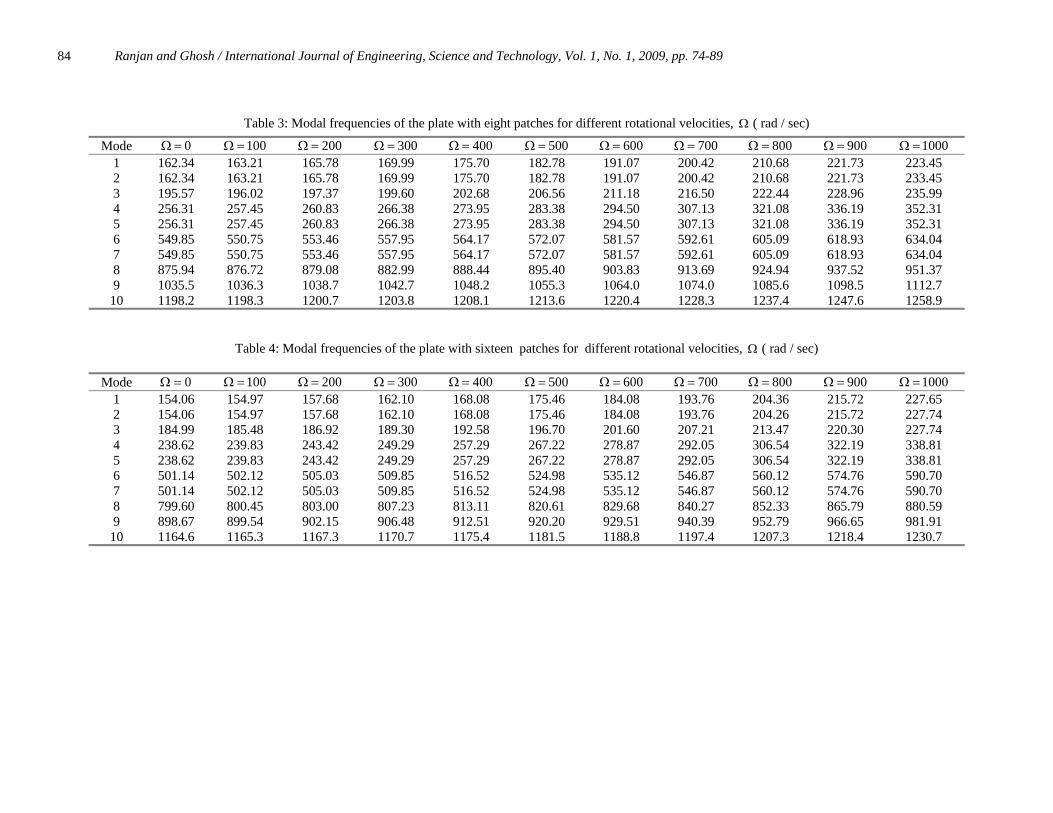
place the patches at higher strain/curvature regions. The first ten mode shapes of the stationary plate rigidly clamped to a core are given in Figure 3. The first or the fundamental mode shape and the second mode of the stationary plate shown in Figures 3(a) and (b) are characterized by a nodal diameter through which the relative phase of displacement changes by about 1800. These two mode shapes have two maximum curvature regions each where the patches are to be located. The third mode shape in Figure 3(c) has nodal point (no strain) at the center, which is rigidly fixed. The maximum deflection point is on the periphery of the disk where the patches may be located. The fourth and fifth mode shapes in Figure 3 have four points of maximum curvature with 900 phase displacement. At these four points patches may be located. In the case of sixth mode in Figure 3(f) and seventh mode in Figure 3 (g), there are three nodal diameters with six points of maximum curvature where the patches may be located. Again the 8th and 9th mode shapes in Figure 3(h) and 3(i) have four nodal diameters with eight points of maximum curvature on the circumference of the disk. The tenth mode shape is characterized by nodal ring in Figure 3(j). The maximum curvature region consists of two circular rings along which patches may be placed. It is interesting to note that with increasing speed the points of maximum curvature changes. Table 3 presents the effect of eight patches on the free vibration of the rotating plate. The eight patches are located in positions 1, 3,5,7,9,11,13,15 as shown in Figure 1. The 1st, 2nd and 4th modes shapes of the plate with eight patches change and that out of eight patches only four patches which lie in the regions of high strains contribute significantly to drop the modal frequency while the contribution of the rest four patches are only partial. Only small drop in the corresponding frequencies are noted in Table 3. For the third mode, additional patches do contribute to vibration control as they lie in the maximum strain region. However, it is noticed that 5th modal frequencies drop for all the rotational speeds considered for evaluation in Table 3. The 5th mode shape remains similar to Figure 3(e) and therefore only four out of eight patches lie in the higher strain region and therefore only four patches contribute effectively to lower the modal frequencies. The 6th and 7th mode are having six antinodes and are having six small regions of higher stain. Some of the patches fall directly in higher curvature region while some of the patches cover partially. So decrease in frequency is noted in Table 3. In case of 8th mode shape, all the eight patches fall directly in the region of higher curvature so drop in modal frequencies are significant. For the 9th mode, all the patches cover the nodal diameters but due to the geometry of the patch and also due to eight small areas of higher strains owing to eight antinodes, the patches cover partially the higher strain areas and therefore drop in frequency for 9th mode shape is also reported but drop in frequency is not significant as it is for 8th mode. The tenth mode is characterized by a circular nodal ring. As the patch locations are on higher curvature region of circumference, so fall in frequency is noticed. This indicates that the proposed eight patches may be used to control the vibration of all the ten modes.
Figure 3 (a) Mode 1 of stationary plate with one nodal diameter, Freq. = 172.06 Hz

Ranjan and Ghosh / International Journal of Engineering, Science and Technology, Vol. 1, No. 1, 2009, pp. 74-89
79
Table 2: Modal frequencies of the plate without any patch / point mass for different rotational velocities, Ω ( rad / sec)
Figure 3(b). Mod 2 of stationary plate with one nodal diameter, Freq. = 172.06 Hz
Mode 0=Ω 100=Ω 200=Ω 300=Ω 400=Ω 500=Ω 600=Ω 700=Ω 800=Ω 900=Ω 1000=Ω 1 172.06 172.87 175.31 179.29 184.71 191.46 199.40 208.38 218.27 228.96 240.34 2 172.06 172.87 175.31 179.29 184.71 191.46 199.40 208.38 218.27 228.96 240.34 3 208.08 208.50 209.76 211.83 214.69 218.31 222.63 227.62 233.22 239.38 246.05 4 278.97 280.03 283.19 288.37 295.48 304.37 314.90 326.90 340.22 354.72 370.24 5 278.97 280.03 283.19 288.37 295.48 304.37 314.90 326.90 340.22 354.72 370.24 6 617.64 618.47 620.97 625.10 630.85 638.15 646.97 652.25 668.90 681.86 696.06 7 617.64 618.47 620.97 625.10 630.85 638.15 646.97 657.25 668.90 681.86 696.06
1156.7 1156.7 1297.0
8 1086.8 1087.5 1089.7 1093.3 1098.3 1104.7 111205 1121.6 1132.0 1143.8 9 1086.8 1087.5 1089.7 1093.3 1098.3 1104.7
255.6 1112.5 1261.7
1121.6 1269.0
1132.0 1277.3
1143.8 1286.6 10 1241.5 1242.0 1243.7 1246.6 1250.5 1

Ranjan and Ghosh / International Journal of Engineering, Science and Technology, Vol. 1, No. 1, 2009, pp. 74-89 80
Figure 3(c). Mode 3 of stationary plate with one nodal point at centre, Freq. = 208.08 Hz
Figure 3. (d) Mode 4 of stationary plate with two nodal diameters, Freq. = 278.97 Hz
Figure 3 (e) Mode 5 of stationary plate with two nodal diameters, Freq. = 278.97 Hz

Ranjan and Ghosh / International Journal of Engineering, Science and Technology, Vol. 1, No. 1, 2009, pp. 74-89 81
Figure 3 (f) Mode 6 of stationary plate with three nodal diameters, Freq. = 617.64 Hz
Figure 3. (g) Mode 7 of stationary plate with three nodal diameters, Freq. = 617.64 Hz
Figure 3 (h) Mode 8 of stationary plate with four nodal diameters, Freq. = 1086.8 Hz

Ranjan and Ghosh / International Journal of Engineering, Science and Technology, Vol. 1, No. 1, 2009, pp. 74-89 82
Figure 3 (i) Mode 9 of stationary plate with four nodal diameters, Freq. = 1086.8 Hz
Figure 3 (j) Mode 10 of stationary plate with one nodal circle, Freq. = 1241.5 Hz
Another configuration with 16 patches as shown in Figure 1 has been examined. The drop in modal frequencies of all the modes is reported in Table 4 for all the rotational speeds. This is because greater number of patches covers the higher strain region more effectively. This suggests that sixteen-patch configuration can be used to control the vibration of spinning disk. It is interesting to note that for 1000 rad/sec rotational speed, the fundamental mode changes its shape and becomes like umbrella similar to Figure 3(c) with highest strain region along the circumference in positive direction. It has been shown that the fundamental mode shape of stationary disc attached to a core with piezoelectric patches fixed in the groove at the outer periphery in higher strain regions is altered at a particular rotation speed of 1000 rad/sec due to increase in stiffness owing to rotation of the disk. This has considerable bearing on modification of fundamental vibration modes of spinning circular disks with central core. In certain applications like sensing and actuating devices, it may be necessary to have an axisymmetric mode shape of spinning disk for the fundamental vibration mode (i.e. mode shape with no nodal diameter,
z
n = 0). 3.2. Natural frequencies and mode shapes with point masses Table 5 represents the modal frequencies of the plate with eight point masses placed at the eight points A, B, C, D, E, F, G, H in Figure 1.The modal frequencies for 1st, 2nd, 3rd, 5th, 6th, 7th, 8th and 10th decrease as additional point masses contribute further to cause the drop in frequencies. The frequencies for 4th and 9th modes do not fall further due to addition of the point masses. Table 6 presents the modal frequencies of the plate with 16 point masses placed at 16 locations from A to P in Figure 1. It is clear that all the modal frequencies drop in comparison to Table 5 for all the speeds. This suggests that the 16 point masses may be able to contain the vibration of the plate for all the ten modes. It is also clear that with 8 patches, all the modal frequencies drop whereas with eight point masses, 4th and 9th modal frequencies remain unaffected. However with 16 patches or point loads, all the modal frequencies fall. It is also noticed that with increase in number of patches or point masses, the reduction in the modal frequencies for the higher modes are greater in case of patches than the point masses.

83 Ranjan and Ghosh / International Journal of Engineering, Science and Technology, Vol. 1, No. 1, 2009, pp. 74-89
4. Forced vibration response and vibration control of rotating plate Forced vibration response and its control through actuation of some of the piezo-electric patches are shown in Figures 4-6. Figure 4 shows the comparison of transverse vibration response of stationary plate without and with eight discrete point masses and eight distributed patches attached at its periphery. As can be seen that all the response peaks do not show reduction in magnitude e.g. in case of patches fourth peak does not show reduction whereas in case of masses third peak does not reduction. This may be due to arbitrary location of measurement chosen. However, first two resonance peaks are reduced significantly in case of plate with patches than plate with masses. Three patches 9, 11 and 13 of the stationary plate with eight patches are then actuated by –0.1 N while patch 2 is actuated by –0.05 N. The magnitude of actuating forces has been selected so that the controlling forces are within ten percent of the disturbing force which in this case is 1.0 N. The location of the control forces are also selected randomly. However, the locations have been chosen so that actuating forces are in a quadrant opposite to the disturbing force. It is presumed that in general this is likely to give required vibration control. Since the system is linear this approach would be applicable to other locations of disturbing forces also. The corresponding vibration response is shown in Figure 5. From Figure 5 it is quite evident that amplitudes at resonant peaks 1, 3 and 4 drop due to actuation while the amplitude at 2nd resonant peak almost remains same. Further, all the four peaks of the plate after actuation in Figure 5 are also lower than the corresponding peaks of the stationary plate without patch / mass in Figure 4. This implies that actuating these four patches improves the vibration control of the stationary plate having eight patches in the frequency range of 0-800 Hz.
Ranjan and Ghosh / International Journal of Engineering, Science and Technology, Vol. 1, No. 1, 2009, pp. 74-89
84
Table 3: Modal frequencies of the plate with eight patches for different rotational velocities, Ω ( rad / sec)
Mode 0=Ω 100=Ω 200=Ω 300=Ω 400=Ω 500=Ω 600=Ω 700=Ω 800=Ω 900=Ω 1000=Ω 1 162.34 163.21 165.78 169.99 175.70 182.78 191.07 200.42 210.68 221.73 223.45 2 162.34 163.21 165.78 169.99 175.70 182.78 191.07 200.42 210.68 221.73 233.45 3 195.57 196.02 197.37 199.60 202.68 206.56 211.18 216.50 222.44 228.96 235.99 4 256.31 257.45 260.83 266.38 273.95 283.38 294.50 307.13 321.08 336.19 352.31 5 256.31 257.45 260.83 266.38 273.95 283.38 294.50 307.13 321.08 336.19 352.31 6 549.85 550.75 553.46 557.95 564.17 572.07 581.57 592.61 605.09 618.93 634.04 7 549.85 550.75 553.46 557.95 564.17 572.07 581.57 592.61 605.09 618.93 634.04 8 875.94 876.72 879.08 882.99 888.44 895.40 903.83 913.69 924.94 937.52 951.37 9 1035.5 1036.3 1038.7 1042.7 1048.2 1055.3 1064.0 1074.0 1085.6 1098.5 1112.7
10 1198.2 1198.3 1200.7 1203.8 1208.1 1213.6 1220.4 1228.3 1237.4 1247.6 1258.9
Table 4: Modal frequencies of the plate with sixteen patches for different rotational velocities, Ω ( rad / sec)
Mode 0=Ω 100=Ω 200=Ω 300=Ω 400=Ω 500=Ω 600=Ω 700=Ω 800=Ω 900=Ω 1000=Ω 1 154.06 154.97 157.68 162.10 168.08 175.46 184.08 193.76 204.36 215.72 227.65 2 154.06 154.97 157.68 162.10 168.08 175.46 184.08 193.76 204.26 215.72 227.74 3 184.99 185.48 186.92 189.30 192.58 196.70 201.60 207.21 213.47 220.30 227.74 4 238.62 239.83 243.42 249.29 257.29 267.22 278.87 292.05 306.54 322.19 338.81 5 238.62 239.83 243.42 249.29 257.29 267.22 278.87 292.05 306.54 322.19 338.81 6 501.14 502.12 505.03 509.85 516.52 524.98 535.12 546.87 560.12 574.76 590.70 7 501.14 502.12 505.03 509.85 516.52 524.98 535.12 546.87 560.12 574.76 590.70 8 799.60 800.45 803.00 807.23 813.11 820.61 829.68 840.27 852.33 865.79 880.59 9 898.67 899.54 902.15 906.48 912.51 920.20 929.51 940.39 952.79 966.65 981.91
10 1164.6 1165.3 1167.3 1170.7 1175.4 1181.5 1188.8 1197.4 1207.3 1218.4 1230.7

Ranjan and Ghosh / International Journal of Engineering, Science and Technology, Vol. 1, No. 1, 2009, pp. 74-89
85
Table 5. Modal frequencies of the plate with eight point masses for different rotational velocities, Ω ( rad / sec)
Table 6: Modal frequencies of the plate with sixteen point masses for different rotational velocities, Ω ( rad / sec)
Mode 0=Ω 100=Ω 200=Ω 300=Ω 400=Ω 500=Ω 600=Ω 700=Ω 800=Ω 900=Ω 1000=Ω 1 161.11 161.98 164.57 168.80 174.55 181.67 190.00 199.39 209.69 220.78 232.53
232.53 2 161.11 161.98 164.57 168.80 174.55 181.67 190.00 199.39 209.69 220.78 3 195.10 195.56 196.92 199.16 202.25 206.15 210.80 216.14 222.11 228.65 235.71 4 258.90 260.02 263.24 268.79 276.24 285.53 296.49 308.94 322.71 337.64 353.57 5 258.90 260.02 263.34 268.79 276.24 285.53 296.49 308.94 322.71 337.64 353.57 6 564.04 564.91 567.51 571.81 577.78 585.37 594.52 605.14 617.17 630.38 645.12 7 564.04 564.91 567.51 571.81 577.78 585.37 594.52 605.14 617.17 630.38 645.12 8 901.59 902.32 904.49 908.11 913.14 919.52 927.37 936.50 946.93 958.60 971.48 9 1086.8 1087.6 1089.9 1093.8 1099.2 1106.0 1114.4 1124.2 1135.4 1148.0 1161.9
10 1165.5 1166.1 1168.0 1171.1 1175.4 1181.0 1187.7 1195.6 1204.7 1214.9 1201.3
Mode 0=Ω 100=Ω 200=Ω 300=Ω 400=Ω 500=Ω 600=Ω 700=Ω 800=Ω 900=Ω 1000=Ω 1 152.00 152.92 155.66 160.12 166.16 173.62 182.31 192.06 202.72 214.15 226.23
226.23 2 152.00 152.92 155.66 160.12 166.16 173.62 182.31 192.06 202.72 214.15 3 184.24 184.72 186.18 188.59 191.89 196.05 200.98 206.64 212.94 219.82 227.22 4 242.61 243.78 247.26 252.97 260.74 270.40 281.77 294.63 308.80 324.12 340.42 5 242.61 243.78 247.26 252.97 260..74 270.40 281.77 294.63 308.80 324.12 340.42 6 523.43 524.34 527.05 531.53 537.75 545.63 555.12 566.11 578.54 592.31 607.32 7 523.43 524.34 527.05 531.53 537.75 545.63 555.12 566.11 578.54 592.31 607.32 8 838.33 839.09 841.35 845.11 850.35 857.04 865.14 874.61 885.41 897.49 910.79
1057.7 9 981.53 982.33 981.71 988.64 994.13 1001.1 1009.6 1019.6 1031.0 1043.7 10 1117.5 1118.1 1120.2 1123.5 1128.3 1134.3 1141.6 1150.2 1160.0 1171.1 1183.3

Ranjan and Ghosh / International Journal of Engineering, Science and Technology, Vol. 1, No. 1, 2009, pp. 74-89 86

Ranjan and Ghosh / International Journal of Engineering, Science and Technology, Vol. 1, No. 1, 2009, pp. 74-89 87
Further, consider the case of the plate with eight patches rotating at 500 rad / sec with four patches 2, 9, 11 and 13 actuated by a force –0.1 N. The vibration response of the plate is shown in Figure 6. It is noticed from Figure 6 that except 2nd peak the vibration amplitude at all other resonance peaks drop significantly due to actuation. The magnitude of the 2nd peak in Figure 6 marginally increases after actuation. The effect of actuation is evident and clearly indicates that actuation of patches may be used as a means of vibration control of the rotating plate in the entire frequency range of 0-800 Hz. Further, the speed of rotation of the plate with eight patches is increased to 800 rad /sec. The patches 2, 9 and 13 are actuated by –0.1 N and patch 11 is actuated by a force of –0.05N. The vibration response is shown in Figure 7. It is noticed from Figure 7 that all the peaks drop due to actuation. Further the peaks due to actuation in Figure 7 are lower than the corresponding peaks of the plate without patch / mass and rotating at 800 rad / sec in Figure 7. This further shows the effectiveness and demonstrates that vibration control can be successfully achieved through actuation of some of the patches in a wide range of the frequencies between 0-800 Hz covering several natural frequencies. It is important to note that other combination of actuating forces and patch locations may also be possible for effective control of the vibration of the plate. 5. Conclusions Natural frequencies of thin spinning plate attached to a rigid core increase significantly with increase in speed. Further discrete patches of distributed masses and discrete point masses when attached to the plate have significant influence on the mode shapes and modal frequencies of the spinning plate. By locating the patches / point masses at higher deflection points / regions, vibration absorption can be achieved. The proposed eight or sixteen discrete patches configuration or the sixteen point masses configuration can be used for controlling the first ten modes of the spinning disk. The reduction in frequencies of higher modes is more in case of plate with a definite number of patches in comparison to the plate with same number of point masses. However, number of the discrete patches or point masses required and their locations depend on the modal frequencies at which vibration control is desired. It has also been shown that discrete patches of piezoelectric ceramics can also be used to actively control the vibration of the spinning disc. It has also been shown that the fundamental mode shape of the stationary disc attached to a central core having piezoelectric ceramic patches fixed in the groove at the outer periphery in higher strain regions is altered at a high rotation speed of 1000 rad/sec due to increase in stiffness owing to rotation of the disk. This has considerable bearings on modification of fundamental vibration modes of spinning circular discs with a central core. In certain applications like sensing and actuating devices, it may be necessary to have an ax symmetric mode shape of spinning disc for the fundamental vibration mode (i.e. mode shape with no nodal diameter, n = 0). References Barasch, S. and Chen, Y., 1972. On the vibration of rotating disk, American Society of Mechanical Engineers, Journal of Applied

Ranjan and Ghosh / International Journal of Engineering, Science and Technology, Vol. 1, No. 1, 2009, pp. 74-89 88
Mechanics, Vol. 39, pp. 1143-1144. Bashmal, S., 2009, In-plane free vibration of circular annular disks, Journal of Sound and Vibration, Vol. 322, pp. 216–226 Bauer H.F. and Eidel W. , 2007, Transverse vibration and stability of spinning circular plates of constant thickness and different boundary conditions, Journal of Sound and Vibration, Vol. 300, pp. 877–895. Chan, J.-S, 2003. Vibration control of a spinning disk, International Journal of Mechanical Sciences, 45, pp. 1269-1282. Chen S. C. and Bogy, D. B., 1992. Effects of load parameters on the natural frequencies and stability of flexible spinning disk with a stationary load system, American Society of Mechanical Engineers, Journal of Applied Mechanics, Vol. 58, pp. 230- 235. Crawley EF, Javier, D.L., 1987. Use of Piezoelectric actuators as elements of intelligent structures, AIAA Journal, pp. 1773-1785. Cook, R.D., 1981. Concepts and Applications of Finite Element Analysis, Second Edition, John Wiley and Sons, New York, Curadelli,, R. O., Ambrosini R.D., Danesi, R.F., 2004. Vibration control by attaching masses to a plate excited by rotary machinery, Journal of Sound and Vibration, Vol. 273 , pp. 1087-1100. Duan, W.H., Wang C.M., Wang C.Y., 2008. Modification of fundamental vibration modes of circular plates with free edges, Journal of Sound and Vibration, Vol. 317, pp. 709–715. Eversman, W. and Dodson, R. O.,1969. Free vibration of a clamped spinning circular disk, American Institute of Aeronautics and Astronautics Journal, Vol. 7, pp. 2010-2012. Ewan, W. D. and Moeller, T. I., 1976. The stability of a spinning elastic discs with transverse load system, American Society of Mechanical Engineers, Journal of Applied Mechanics, Vol. 43, pp. 485-490. Ferretti, G, Magnani, G., Rocco, P., 2002. Modeling and experimental analysis of the vibrations in hard disk drives, IEEE/ASME Transactions on Mechatronics, Vol. 7, No. 2, pp.152-159. Grimes, R.G., Lewis J.G., Simon H.D., 1994. A Shifted Block Lanczos Algorithm for Solving Sparse Symmetric Generalized Eigen problems, SIAM Journal Matrix Analysis Applications, Vol. 15, No. 1, pp. 228-27. Huang, S. C. and Yu, S.C., 1990. On the free vibration of rotating annular plates elastically restrained at discrete locations, Journal of Chinese Society of Mechanical Engineers, 11, pp.488-498. Huang, S.C. and Wu, C.H., 1998. Frequency Analysis of rotating plate with external beam supports, Journal of Sound & Vibration, Vol. 210, No. 4, pp.415-429. Koo K.-N., 2006, Vibration analysis and critical speeds of polar orthotropic annular disks in rotation, Composite Structures, Vol. 76, pp 67-72. Lakshminarayana, H. V., 1986. Finite element analysis of rotating laminated composite annular disks, Composites, 17, pp.42-48. Lamb, H. and Southwell, R.V., 1922. The vibration of spinning disk, Proceedings of the Royal Society, U.K., 99, pp. 272-280. Liang, D. -S., Wang H. –J., Chen L. –W, 2002. Vibration and stability of rotating polar orthrotropic annular disks subjected to a stationary concentrated transverse load, Journal of Sound and Vibration, Vol. 250, No. 5, pp.795-811. Lee, H.P. and Ng, T.Y., 1995. Vibration and critical speeds of a spinning annular disk of varying thickness, Journal of Sound and Vibration, Vol. 187, No. 1, pp. 39-50. Rajakumar, C. and Rogers, C.R., 1991. The Lanczos algorithm applied to unsymmetric generalized eigenvalue problems, International Journal for Numerical Method in Engineering, Vol. 32, pp.1009-1026. Ramaiah, G. K., 1981. Natural frequencies of spinning annular plates, Journal of Sound and Vibration, 74, pp.303-310. Shahbab, A. A. S., 1993. Finite element analysis for the vibration of variable thickness disks, Journal of Sound and Vibration, 162, pp. 67-68. Sinha, S. K., 1998a. Free vibration of a thick spinning annular disk with distributed masses at the outer edge, Journal of Sound and Vibration, Vol. 122 pp. 217-231. Sinha, S. K., 1998b. On free vibration of a thin spinning disk stiffened with an outer reinforcing ring, American Society of Mechanical Engineers, Journal of Vibration, Acoustics, Stress and Reliability in Design, 110, pp.507-514. Southwell, R.V., 1922. On the free vibrations of a uniform circular disc clamped at its center and on the effects of rotation, Proceedings of the Royal Society, U.K., 101, pp. 133-153. Wang, C.Y., 2005. Vibration of a circular plate with an attached core, Journal of Sound and Vibration, 280 , pp.1075-1082. Biographical notes
Dr. Vinayak Ranjan received his graduate degree in Mechanical Engineering in 1991 from Bihar University, India and Ph.D. in Mechanical Engineering from Banaras Hindu University, Varanasi, India in 2006. Dr. Ranjan joined as a Scientist (Mechanical Engineering) in Indian Council of Agricultural Research, India in 1994 and remained at various scientific positions till 2007. He has executed a number of projects sponsored by ICAR and industries. Dr. Ranjan joined as Assistant Professor in the Department of Mechanical Engineering and Mining machinery Engineering, Indian school of Mines, Dhanbad, India in 2008. Dr. Ranjan’s research interest areas are: Finite element analysis, Vibration, and Dynamics of Mechanical Systems. Prof. M.K. Ghosh received his B.S. (Mechanical Engineering) in 1966 from Banaras Hindu University, Varanasi, India, M.Tech in 1968 and Ph.D. in 1979 in Mechanical Engineering respectively from Indian Institute of Technology, Kharagpur, India. Professor Ghosh joined as a faculty member in 1969 in the Department of Mechanical Engineering, Institute of Technology, Banaras Hindu University, and Varanasi, India and is a Professor since 1993. He has worked as a NRC Research Associate during 1982-1984 as a senior NRC Research Associate during 1989-90 at the

Ranjan and Ghosh / International Journal of Engineering, Science and Technology, Vol. 1, No. 1, 2009, pp. 74-89 89
NASA Lewis Research Center, Cleveland, OH (USA). He was a Professor of Mechanical Engineering in the Department of Mechanical Engineering at I.I.T. Kharagpur during 1987-88. Professor Ghosh is a member of the American Society of Mechanical Engineers since 1984, a Life Member of the Tribology Society of India (TSI) and was a member of the Executive Committee of the TSI during 1995-97. He is a member of the honorary editorial board of the journal "Advances in Vibration Engineering", the scientific journal of the “Vibration Institute of India”. He is a recipient of the University Grants Commission of India "Career Award" in Engineering in 1984. Professor Ghosh's research interest areas are: Tribology, Vibration, and Dynamics & Control of Mechanical Systems. He has published about 45 papers in peer reviewed international journals e.g. Tribology Transactions of ASME, Proc. of I. Mech. E., U.K., Tribology International, Int. J. of Wear, Int. J. of Mechanical Sciences, Int. J. of Machine Tools & Manufacturing etc. Professor Ghosh has supervised about 35 graduate thesis and 6 Ph.D. students. Received July 2009 Accepted September 2009 Final acceptance in revised form September 2009