transportation related earthborne … related...intensity to be felt, as well as heard. these low...
TRANSCRIPT

Technical Advisory, Vibration TAV-02-01-R9601
California Department of Transportation Division of Environmental Analysis
Office of Noise, Air Quality, and Hazardous Waste Management Sacramento, CA
TRANSPORTATION RELATED EARTHBORNE VIBRATIONS
(Caltrans Experiences)
Technical Advisory, Vibration TAV-02-01-R9601
February 20, 2002
Prepared by Rudy Hendriks – Caltrans Retired Annuitant
NOTICE:
This document is a revision of technical advisory TAV-96-01-R9201 with the same title, prepared by the same author, dated June 13, 1996. This revision does not alter the basic information of the earlier version, except for the Rayleigh wave propagation equation (see eq.1 and associated eq.2), which was in error and has been corrected. The text associated with the equation as well as the text in figure 1 has also been changed. The error did not affect the vibration dropoff curve in figure 1. Some other changes were made in formatting and wording.
This document is not an official policy, standard, specification or regulation and should not be used as such. Its contents are for informational purposes only. Any views expressed in this advisory reflect those of the author, who is also responsible for the accuracy of facts and data presented herein. The latter were derived from Caltrans vibration studies from 1958 to 1994, and the author’s vibration experiences from 1980 to 1994 at the Caltrans Transportation Laboratory (Translab) in Sacramento, CA.

Technical Advisory, Vibration TAV-02-01-R9601
TABLE OF CONTENTS
Page
INTRODUCTION ............................................................................................. 1 BACKGROUND .............................................................................................. 1 FUNDAMENTALS OF EARTHBORNE VIBRATIONS ................................... 2 Vibration Sources .................................................................................... 2 Amplitude and Frequency ....................................................................... 2 Propagation .............................................................................................. 4 TRANSPORTATION-RELATED VIBRATIONS ............................................. 5 Sources .................................................................................................... 5 Descriptor Used by Caltrans .................................................................. 6 Propagation of Transportation-Related Vibrations .............................. 6 Caltrans Vibration Criteria .................................................................... 10 Typical Traffic Vibration Levels ........................................................... 13 Construction Vibration Levels ............................................................. 15 Train Vibration Levels .......................................................................... 16 Impacts ................................................................................................... 17 Mitigation ............................................................................................... 18 Link With Historical Data ...................................................................... 18 Vibration Monitoring Eguipment ......................................................... 19 Vibration Study Approach and Instrument Setup ................................ 20 Vibration Reports ................................................................................. 22 Field Review and Screening of Possible Vibration Problems ......... 25 APPENDIX - BASIC FORMULAE .............................................................. 28

Technical Advisory, Vibration TAV-02-01-R9601
INTRODUCTION
This Technical Advisory is intended to give district environmental, materials, design,
construction and other concerned personnel a basic understanding of transportation
related earthborne vibrations. The advisory covers general vibration principles,
vibrations caused by construction and operation of transportation facilities, criteria
used by the California Department of Transportation (Caltrans), impacts, vibration
study approaches, possible mitigation, and screening procedures to identify potential
vibration problems in the field.
District personnel are usually the first to be contacted by the public when vibration
problems occur. Until 1994, the district personnel in turn contacted the Caltrans
laboratory (TransLab) and requested either an assesment of the problem or a vibration
field study. In 1994, Translab discontinued the field studies because of a
reorganization. Presently, HQ Division of Environmental Analysis, Noise, Air Quality
and Hazardous Waste Management Office, Noise and Vibration Branch is responsible
for providing guidance on potential vibration problems.
The information in this advisory will enable district personnel to participate in
assessing and screening routine vibration complaints as well as provide background
information for the oversight of more complex studies. This advisory will also be a
useful source of information for developing contract specifications and oversight.
BACKGROUND
Caltrans has performed earthborne vibration studies since 1958. In 1976, a landmark
TransLab vibration research report titled "Survey of Earth-borne Vibrations due to
Highway Construction and Highway Traffic", Report No. CA-DOT-TL-6391-1-76-20,
compiled a summary of results, findings, and conclusions of 23 studies completed in
the 17 year period between 1958 and 1975. Since then many more studies have been
performed. Most of these fall into the following three categories:
• Highway traffic vibrations • Construction vibrations • Train/light rail vibrations
The main concerns of vibrations involve:
• Annoyance • Damage • Disruption of vibration sensitive operations or activities • Triggering of land slides
1

Technical Advisory, Vibration TAV-02-01-R9601
The sites investigated included private residences, factories, aerospace and defense
plants, electronic laboratories, radio station, movie studio, etc., and even a major cake
and pastry bakery.
Because of similarities between the disciplines of noise and vibrations, the former Noise
Section took over the responsibilities for vibration studies from the Electrical
Instrumentation Testing and Research Section in July, 1980. Almost two-thirds of the
above mentioned studies were performed by the Noise Section, which, in 1994 was
absorbed by the newly created Office of Environmental Engineering of the
Environmental Program. The individual study reports are on file at the Office of
Environmental Engineering. This advisory incorporates information and experience
gained in all Caltrans vibration studies from 1958-1994.
FUNDAMENTALS OF EARTHBORNE VIBRATIONS Vibration Sources
Sources of earthborne vibrations include natural phenomena (earthquakes, volcanic
eruptions, sea waves, landslides, etc.), or manmade causes (explosions, machinery,
traffic, trains, construction equipment, etc.). Vibration sources may be continuous
such as factory machinery, and transient, such as explosions.
A distinction must be made between earthborne and airborne vibrations. Some
sources, such as jet aircraft, rockets, explosions, sonic booms, locomotives, and even
trucks under certain conditions, can create low frequency airborne noise of enough
intensity to be felt, as well as heard. These low frequency airborne blasts or rumbles
are often erroneously perceived as earthborne vibrations.
As is the case with airborne sound, earthborne vibrations may be described by
amplitude and frequency.
Amplitude and Frequency
In airborne sound, amplitude is described by common logarithm of the square of the
ratio of pressure fluctuations around mean air pressure divided by a reference
pressure, and is expressed in logarithmic units of decibels. The pressure fluctuations
propagate in waves of alternating compressed and rarefied air. The rate at which these
waves radiate outward from their source is called the speed of sound, which is the wave
velocity. Air is an elastic medium through which the waves travel.
In earthborne vibrations, amplitude is described by the local movement of soil particles.
This movement must not be confused with wave velocity.
2

Technical Advisory, Vibration TAV-02-01-R9601
To distinguish between wave velocity and particle motion, consider the analogy of
ripples on a lake and a floating cork. Wave velocity (in air, speed of sound) is analogous
to the velocity of the ripples. Particle motion may be compared to the bobbing of the
cork as the ripples pass by. The bobbing of the cork represents the local movement of
the soil particles as earthborne vibration waves pass through the soil. The soil acts as
an elastic medium.
The amplitude of particle motion may be described three ways:
1. Particle displacement - the distance the soil particles travel from their original position. Units are millimeters (mm). inches (in)
2. Particle velocity - the velocity of the soil particles. Units are inches per second (in/sec) or millimeters per second (mm/sec). Sometimes expressed logarithmically in decibels (dB) with reference to a specified unit of velocity such as .001 in/sec, or 0.001 mm/sec.
3. Particle acceleration - the acceleration of the soil particles. Units are inches per second per second (in/sec2), millimeters per second per second (mm/sec2), or g-force (g = acceleration of gravity = 32.2 feet per second per second (ft/sec2) = 9.81 meter per second per second (m/sec2). Sometimes expressed logarithmically in decibels (dB) with reference to a specified unit of acceleration, such as 1 g, or 0.001g.
For a perfect sine wave produced by a single vibration frequency there exists a simple
relationship between the above three measures of amplitude (see Appendix). If the
frequency and amplitude of one descriptor is known, the other two can easily be
calculated. For waves consisting of many frequencies, and therefore not sine waves,
the relationships become much more complicated.
There is a 90 degree phase shift between the three descriptors, i.e. velocity is 90
degrees out of phase with displacement, acceleration is 90 degrees out of phase with
velocity, and acceleration is 180 degrees out of phase with displacement. To illustrate
this, we might imagine a pendulum just released from a point furthest away from its
stationary position. If we arbitrarily call this position the extreme positive (+) position of
the pendulum, the stationary point 0, and the region beyond the stationary point a
negative (-) position, we observe the following:
• at the point of release, the displacement (distance from stationary or 0 displacement position) is maximum and positive (+).
• the velocity at the point of release is 0.
• the acceleration at the point of release is at its maximum, in the direction towards the negative (-).
This can be worked out the same for other pendulum positions. For instance, as the
pendulum swings through the stationary position, the displacement is 0, the velocity is
maximum in the negative (-) direction, and the acceleration is 0. Once past the
3

Technical Advisory, Vibration TAV-02-01-R9601
stationary point the pendulum decelerates in the negative (-) direction which is the
same as increasing acceleration in the positive (+) direction.
Vibration amplitudes are usually expressed as either "peak", as in peak particle
velocity, or "rms" (root mean square), as in rms acceleration. The relationship between
the two is the same as with noise. The rms value is approximately 0.71 x the peak
value for a sine wave representing iether displacement, velocity, or acceleration.
Finally, the direction in which vibrations are measured, analyzed or reported should be
specified (vertical, horizontal longitudinal, horizontal transverse, or the resultant of all
three motions). For example, Caltrans most often uses a peak vertical particle velocity
descriptor, because vibrations along the ground surface are most often (although not
always) greatest in the vertical direction.
Propagation
Propagation of earthborne vibrations is complicated because of the endless variations in
the soil through which waves propagate.
The relationship between frequency (f), period (T), wave length (λ), and wave velocity (c)
is the same as that in noise, that is:
f=1/T and f=c/ λ
However, the wave velocity (c, sometimes also called the phase velocity) in soils varies
much more than the speed of airborne sound does, and is often also frequency
dependent (the speed of sound only varies with temperature). As a consequence,
wavelength cannot readily be calculated when frequency is known and vice versa,
unless the wave velocity happens to be known also.
There are three main wave types of concern in the propagation of earthborne vibrations:
1. Surface or Rayleigh waves, which as the name implies, travel along the ground surface. They carry most of their energy along an expanding cylindrical wave front, similar to the ripples produced by throwing a rock into a lake. The particle motion is retrograde elliptical, more or less perpendicular to the direction of propagation.
2. P-waves, or compression waves. These are body waves that carry their energy along an expanding spherical wave front. The particle motion in these waves is longitudinal, "push-pull". P-waves are analogous to airborne sound waves.
3. S-waves, or shear waves. These are also body waves, carrying their energy along an expanding spherical wave front. Unlike P-waves, however, the particle motion is transverse, or perpendicular to the direction of propagation.
As wave fronts move outward from a vibration source, their energy is spread over an
ever increasing area. The more rapidly this area increases, the more quickly the energy
intensity (energy per unit area) decreases. The areas of cylindrical Raleigh wave fronts
4

Technical Advisory, Vibration TAV-02-01-R9601
do not increase as rapidly with distance as do the body (P- and S-) waves.
Consequently, the energy intensities of Raleigh waves attenuate at a lesser rate with
distance than those of body waves.
The spreading of energy over ever increasing areas is called geometric spreading
(geometric attenuation) and the difference in attenuation rates between surface and
body waves is analogous to that of line sources and point sources, respectively, in
airborne sound. Geometric attenuation also results of encountering more soil mass as
the area of the wave front increases.
Geometric attenuation is not the only attenuation encountered with distance.
Hysteretic attenuation, or material damping, results from energy losses due to internal
friction, soil layering, voids, etc. The amount of hysteretic attenuation varies with soil
type, condition, and frequency of the source.
These variations make it much more difficult to predict vibration levels at specific
locations, than it is to predict noise levels.
In general, manmade earthborne vibrations attenuate rapidly with distance from the
source. Even the more persistent Rayleigh waves decrease relatively quickly.
Manmade vibration problems are therefore confined to short distances from the source.
In contrast, natural vibration problems are often wide spread. An obvious example is
an earthquake which can cause damage over large areas, due to the release of
enormous quantities of energy.
TRANSPORTATION RELATED EARTHBORNE VIBRATIONS Sources
Caltrans is most commonly concerned with three types of transportation related
earthborne vibration sources:
• Normal highway traffic - heavy trucks, and quite frequently buses, generate the highest earthborne vibrations of normal traffic. Vibrations from these vary with pavement conditions. Pot holes, pavement joints, differential settlement of pavement, etc., all increase the vibration levels.
• Construction equipment - pile driving, pavement breaking, blasting, and demolition of structures generate among the highest construction vibrations.
• Heavy and light rail operations - diesel locomotives, heavily loaded freight cars, and operations such as coupling create the highest rail traffic vibrations.
Of the above three types, construction vibrations are of greatest concern. The four
operations mentioned under construction vibrations are potentially damaging to
buildings at distances of less than 7.5 m (25 ft) from the source.
5

Technical Advisory, Vibration TAV-02-01-R9601
Descriptor Used By Caltrans
With the exception of some construction operations such as pile driving, pile hole
drilling, and perhaps some deep excavations, all vibrations generated by construction
or operation of surface transportation facilities are mainly in the form of surface or
Raleigh waves. Studies have shown that the vertical components of transportation
generated vibrations are the strongest and that peak particle velocity correlates best
with damage and complaints. For these reasons, Caltrans adopted the Peak Vertical
Particle Velocity descriptor, with units of mm/sec or in/sec.
A great advantage of using this descriptor is that for a frequency range of 1 - 80 Hz
damage levels in terms of velocity tend to be independent of frequency. The same is
true for complaint levels within a range of 8 - 80 Hz. Velocity is the product of
frequency, displacement and a constant (see appendix). It appears that within the
above frequency ranges a doubling of frequency will offset a halving of displacement
and vice versa; i.e. the effects of the product of the two tend to remain equal. Typical
transportation and construction vibrations fall within the above frequency ranges.
They typically range from 10 - 30 Hz, and usually center around 15 Hz.
From the above we can surmise that not only the effects of displacement are frequency
dependent, but also those of acceleration. The latter is related to the former by the
frequency times a constant squared (see appendix). Thus, criteria levels in terms of
displacement or acceleration need to be accompanied by a frequency.
Propagation of Transportation Related Vibration
Raleigh (Surface) Wave Drop-off - Surface waves generated by traffic, trains, and most
construction operations tend to attenuate with distance according to the following
equation:
V= V0(D0/D)0.5eα(D0-D) (eq. 1) where: V = Peak particle velocity at distance D V0 = Peak particle velocity at reference distance D0 D0 = Reference distance D = Distance for which vibration level needs to be calculated e = Base of natural logarithm = 2.718281828 α = Soil parameter
The soil parameter α can be determined by simultaneous vibration measurements at a
minimum of two different distances from a source. One distance should be near the
source, ideally between4.5 and 7.5 m (15 -25 ft). The other should be farther away
from the source, ideally at or beyond the farthest point of interest, but at a location
where the source is still measurable and not contaminated by other vibrations. A third
6
Technical Advisory, Vibration TAV-02-01-R9601
point in between is recommended for confirmation. Note that the value of α depends on
the distance units used. The reason for this is that the exponential (D0 - D) α needs to
be a constant value while the value of (D0 - D) changes with the units used (normally,
m or ft). Therefore, the relationship between α (based on m) and α (based on ft) is:
α (based on m) = 3.281α (based on ft), and α (based on ft) = 0.305 α (based on m)
α can be calculated from the vibration measurements by rewriting eq. 1 as:
α = (lnV2 + lnD - lnV02 - lnD0)/2(D0 - D) (eq. 2) where "ln" denotes "natural logarithm"
Once α is calculated from the measurements it can be used in eq. 1 to calculate
vibrations for any other distance, given the same reference source.
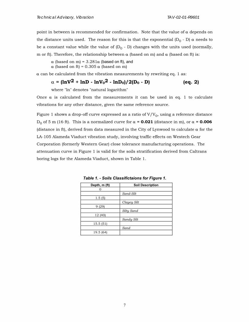
Figure 1 shows a drop-off curve expressed as a ratio of V/V0, using a reference distance
D0 of 5 m (16 ft). This is a normalized curve for α = 0.021 (distance in m), or α = 0.006
(distance in ft), derived from data measured in the City of Lynwood to calculate α for the
LA-105 Alameda Viaduct vibration study, involving traffic effects on Westech Gear
Corporation (formerly Western Gear) close tolerance manufacturing operations. The
attenuation curve in Figure 1 is valid for the soils stratification derived from Caltrans
boring logs for the Alameda Viaduct, shown in Table 1.
Table 1. - Soils Classifictaions for Figure 1. Depth, m (ft) Soil Description
0 Sand-Silt
1.5 (5) Clayey Silt
9 (29) Silty Sand
12 (40) Sandy Silt
15.5 (51) Sand
19.5 (64)
7

Technical Advisory, Vibration TAV-02-01-R9601
Figure 1. Typical Normalized Distance Attenuation Ratio Curve of Earthborne Surface Vibrations (Reference Distance, Do = 5 m)
0
0.050.1
0.15
0.2
0.250.3
0.35
0.40.45
0.5
0.55
0.60.65
0.7
0.750.8
0.85
0.9
0.951
1.05
5 10 15 20 25 30 35 40 45 50 55 60 65 70 75 80 85 90 95 100
Distance (D) from Source, m
V/Vo
Rat
io (=
1.00
at D
o =
5 m
) V/V0 = [D0/D]0.5 eα(Do-D) where: V = Vib. Level at D V0 = Vib. Level at D0 = 5 m e = Base of natural log = 2.718281828 α = Soil parameter = 0.021
The curve is representative of many locations in the L.A. Basin, and also of various
locations in Sacramento, and can be used for estimating traffic, train, and most
construction vibration drop-offs with distance. To use the curve, the vibration level V1
must be known at a given distance D1 near the source, preferably between 5 and 15 m
(16 and 50 ft). The vibration level V2 at the distance of interest D2 can then be
calculated as follows:
V2 = (V2/V0)/(V1/V0) . V1
(the ratio’s V2/V0 and V1/V0 can be obtained from Figure 1)
8

Technical Advisory, Vibration TAV-02-01-R9601
For example, if the vibration level is known to be 3.2 mm/s (peak particle velocity) at a
distance of 12 m, the vibration level at 58 m can be estimated from (0.09/0.55) x 3.2
mm/s = 0.5 mm/s.
Pile Driving Vibration Drop-off - During pile driving, vibration levels near the source
depend mainly on the soil's penetration resistance. In soils such as sand and silt, this
resistance is relatively low with the result that a large portion of the impact energy is
used to advance the pile. Less energy is then available for generating ground
vibrations. In clay soils, however, the penetration resistance is higher and more energy
is available for ground vibrations. The resistance provided by the soils consists of
friction along the sides of the pile as well as compressional resistance due to the
transfer of energy of the pile tip to the soil. This appears to generate body waves as
opposed to surface waves by other construction operations.
The energy of a pile driver is of course also influential on the vibration level at the
source. There is a relationship between vibration level and energy. If pile driver energy
changes from E1 to E2, the vibration level at a certain location changes from V1 to V2,
where:
V VEE2 1
2
1= ( ) (Eq. 3)
Example: E1 = 68,000 J (50,000 ft lbf)
E2 = 111,900 J (82,500 ft lbf)
V1 = 2.8 mm/s
Then: V2 = 2 8 = 3.6 mm/sec 111 90068 000
. ,,
( )
Vibrations of pile driving appear to drop off differently than the Raleigh waves, probably
due to the presence of a significant proportion of body waves. Pile driving vibrations
tend to drop off with distance according to the following equation:
V = V0.(D0/D)k (Eq. 4)
where: V, V0, D0, and D are same as defined in Eq. 1, and k = soil parameter (no units)
(Note that α and k are different parameters; whereas the value of α is dependent on the distance units used (m or ft), the value of k - which depends only on the ratio of distances - is independent of distance units used.)
9

Technical Advisory, Vibration TAV-02-01-R9601
Generally, the values of "k" lie between 1 to 1.5 (approaching 1 for sandy soils and 1.5
for clay soils), although values > 1 and < 1.5 have been encountered.
The value of "k" can be determined experimentally at different distances from a pile
driver, similarly to the previously described derivation of α. For this purpose, Eq. 4 can
be rewritten as:
k = (LogV - LogV0)/(Log D0 - LogD) (eq. 5)
Caltrans Vibration Criteria
There are no FHWA or state standards for vibrations. The traditional view has been
that highway traffic and construction vibrations pose no threat to buildings and
structures, and that annoyance to people is no worse than other discomforts
experienced from living near highways.
Damage - A considerable amount of research has been done to correlate vibrations from
single events such as dynamite blasts with architectural and structural damage. The
U.S. Bureau of Mines has set a "safe blasting limit" of 50 mm/s (2 in/sec). Below this
level there is virtually no risk of buiding damage.
“Safe” levels for continuous vibrations from sources such as traffic are not as well
defined. The Transport and Road Research Laboratory in England has researched
continuous vibrations to some extent and developed a summary of vibration levels and
reactions of people and the effects on buildings (Table 2). These are the criteria used by
Caltrans to evaluate the severity of vibration problems. Traffic, train, and most
construction vibrations (with the exception of pile driving, blasting, and some other
types of construction/demolition) are considered continuous. The "architectural
damage risk level" for continuous vibrations ( peak vertical particle velocity of 5
mm/sec or 0.2 in/sec) shown in Table 2 is one tenth of the maximum “safe” level of 50
mm/sec (2 in/sec) for single events.
All damage criteria for buildings are in terms of ground motion at the buildings'
foundations. No allowance is included for the amplifying effects of structural
components. Obviously, the way a building is constructed and the condition it is in
determines how much vibration it can withstand before damage appears. Table 2
shows a recommended upper level of 2.0 mm/s (0.08 in/sec) for continuous vibrations
to which "ruins and ancient monuments" should be subjected. This criterion level may
also be used for historical buildings, or buildings that are in poor condition.
Relatively little information is available concerning the damaging effects of pile driving.
Although technically a series of single events, pile driver blows occuring often enough in
10

Technical Advisory, Vibration TAV-02-01-R9601
a confined area could cause damage at a lower level than the single event criterion of
50 mm/s (2 in/sec). Caltrans has experienced some minor damage from sustained
Table 2 - Reaction of People and Damage to Buildings
at Various Continuous Vibration Levels
Vibration Level (Peak Particle Velocity)*
mm/s in/sec Human Reaction Effect on Buildings 0.15-0.30 0.006-0.019 Threshold of perception;
possibility of intrusion Vibrations unlikely to cause damage of any type
2.0 0.08 Vibrations readily perceptible
Recommended upper level of the vibration to which ruins and ancient monuments should be subjected
2.5 0.10 Level at which continuous vibrations begin to annoy people
Virtually no risk of “architectural” damage to normal buildings
5.0 0.20 Vibrations annoying to people in buildings (this agrees with the levels extablished for people standing on bridges and subjected to relative short periods of vibrations)
Threshold at which there is a risk of “architectural” damage to normal dwelling - houses with plastered walls and ceilings Special types of finish such as lining of walls, flexible ceiling treatment, etc., would minimize “architectural” damage
10-15 0.4-0.6 Vibrations considered unpleasant by people subjected to continuous vibrations and unacceptable to some people walking on bridges
Vibrations at a greater level than normally expected from traffic, but would cause “architectural” damage and possibly minor structural damage.
* The vibration levels are based on peak particle velocity in the vertical direction. Where human reactions are concerned, the value is at the point at which the person is situated. For buildings, the value refers to the ground motion. No allowance is included for the amplifying effect, if any, of structural components.
Source: “A Survey of Traffic-induced Vibrations” by Whiffen and Leonard, Transport and Road Research Laboratory, RRL Report LR418, Crowthorne, Berkshire, England, 1971.
pile driving at about 7.5 - 9 mm/s (0.30 - 0.35 in/sec) peak vertical particle velocity
vibration level on the ground next to an existing parking structure. The extent of the
damage was some crumbling of mortar used to fill wall joints. In that instance the
distance to the pile driving was slightly greater than 5 m (17 ft). The pile driver energy
and the soil conditions were unknown. It is likely that the ground vibrations were
amplified by the structure, causing the damage.
11

Technical Advisory, Vibration TAV-02-01-R9601
On the whole, the architectural damage criterion for continuous vibrations, 5 mm/s
(0.2 in/sec) appears to be conservative even for sustained pile driving. Pile driving
levels often exceed 5 mm/s (0.2 in/sec) at distances of 15 m (50 ft), and 13 mm/s (0.5
in/sec) at 7.5 m (25 ft). Pile driving has been done frequently at these distances
without apparent damage to buildings (with the previously mentioned exception). The
criterion level for pile driving is therefore somewhere between 5 and 50 mm/s (0.2 and
2 in/sec). The 50 mm/s (2 in/sec) single event criterion is still being used by some
organizations and engineering firms as a safe level for pile driving. Although never
measured by Caltrans, calculations show that this level will be probably exceeded
within 2 m (6 ft) from a 68,000 J (50,000 ft lbf) pile driver. This level is probably a “safe”
criterion to use for well engineered and reinforced structures. For normal dwellings,
however, pile driving peaks should probably not be allowed to exceed 7.5 mm/s (0.3
in/sec). In any case, extreme care must be taken when sustained pile driving
occurs within 7.5 m (25 ft) of any building, and 15-30 m (50-100 ft) of a historical building, or building in poor condition.
When high levels of construction vibrations (such as from pile driving, demolition, and
pavement breaking) are expected at residences or other buildings, it is recommended
that a detailed "crack survey" be undertaken BEFORE the start of construction
activities. The survey may be done by photographs, video tape, or visual inventory, and
should include inside as well as outside locations. All existing cracks in walls, floors,
driveways, etc. should be documented with sufficient detail for comparison after
construction to determine whether actual vibration damage has occurred.
Annoyance - The annoyance levels in Table 2 should be interpreted with care.
Depending on the activity (or inactivity) a person is engaged in, vibrations may be
annoying at much lower levels than those shown in Table 2. Elderly, retired, or ill
people staying mostly at home, people reading in a quiet environment, people involved
in vibration sensitive hobbies or other activities are but a few examples of people that
are potentially annoyed by much lower vibration levels. Most routine complaints of
traffic vibrations come from people in these categories. To them, even vibrations near
the threshold of perception may be annoying.
Frequently, low level traffic vibrations can cause irritating secondary vibrations, such
as a slight rattling of doors, windows, stacked dishes, etc. These objects are often in a
state of neutral equilibrium and readily respond to very low levels of vibrations. The
rattling sound gives rise to exaggerated vibration complaints, even though there is very
little risk of damage.
12

Technical Advisory, Vibration TAV-02-01-R9601
Other criteria - At times, other criteria may be necessary to address very specific
concerns. For example, vibration sensitive manufacturing or calibration processes,
such as close tolerance machining, laboratories calibrating sensitive electronic
equipment, use of electron microscopes, etc. often require vibration criteria that are
much lower than the threshold of perception level.
Determining the specific criterion level for such sites is no easy task, and requires the
cooperation of the engineers, technicians, or managers involved with the operations.
Frequently, even those experts do not know at what level of vibrations their operations
will be disturbed, and tests involving generation of vibrations (such as running a heavy
truck over 2"x4" wooden boards outside the plant), vibration monitoring equipment,
and a test operation must be performed.
Typical Traffic Vibration Levels
From Figure 1 typical relationships of traffic vibrations vs. distance from a freeway can
be developed. For instance, vibration data of truck passbys are characterized by peaks
that are considerably higher than those generated by automobiles. These peaks last no
more than a few seconds and often only a fraction of a second, indicating a rapid drop-
off with distance. Figure 1 showed that at 15 m (50 ft) from the centerline of the
nearest lane, truck vibrations are about half of those measured near the edge of
shoulder (5 m, or about 15 ft from the centerline of the near lane). At 30 m (100 ft) they
are about one fourth, at 60 m (200 ft) about one tenth, and at 90 m (300 ft) less than
one twentieth. These rough estimates are supported by years of measurements
throughout California.
Because of the rapid dropoffs with distance, even trucks traveling close together often
do not increase peak vibration levels substantially. In general, more trucks will show
up as more peaks, not necessarily higher peaks. Wavefronts emanating from several
trucks closely together may either cancel or partially cancel (destructive interference),
or reinforce or partially reinforce (constructive interference) each other, depending on
their phases and frequencies. Since traffic vibrations can be considered random, the
probabilities of total destructive or constructive interference are extremely small.
Coupled with the fact that two trucks cannot occupy the same space, and the rapid
drop-off rates, it is understandible that two or more trucks normally do not contribute
significantly to each other's peaks. It is, however, good practice to try and include the
worst combinations of truck clusters with heavy loads in traffic passby vibration
measurements. This obviously requires a good view of the traffic, or an observer who is
in communication with the instrument operator.
13
Technical Advisory, Vibration TAV-02-01-R9601
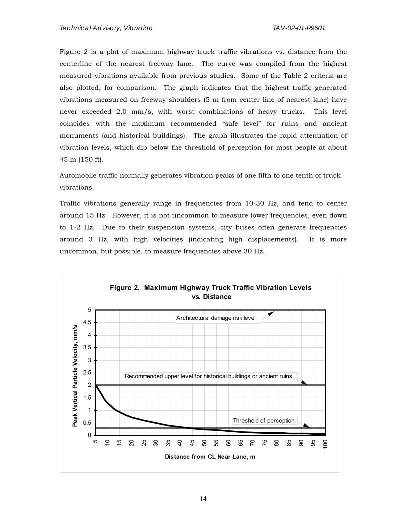
Figure 2 is a plot of maximum highway truck traffic vibrations vs. distance from the
centerline of the nearest freeway lane. The curve was compiled from the highest
measured vibrations available from previous studies. Some of the Table 2 criteria are
also plotted, for comparison. The graph indicates that the highest traffic generated
vibrations measured on freeway shoulders (5 m from center line of nearest lane) have
never exceeded 2.0 mm/s, with worst combinations of heavy trucks. This level
coincides with the maximum recommended “safe level” for ruins and ancient
monuments (and historical buildings). The graph illustrates the rapid attenuation of
vibration levels, which dip below the threshold of perception for most people at about
45 m (150 ft).
Automobile traffic normally generates vibration peaks of one fifth to one tenth of truck
vibrations.
Traffic vibrations generally range in frequencies from 10-30 Hz, and tend to center
around 15 Hz. However, it is not uncommon to measure lower frequencies, even down
to 1-2 Hz. Due to their suspension systems, city buses often generate frequencies
around 3 Hz, with high velocities (indicating high displacements). It is more
uncommon, but possible, to measure frequencies above 30 Hz.
Figure 2. Maximum Highway Truck Traffic Vibration Levels vs. Distance
0
0.5
1
1.5
2
2.5
3
3.5
4
4.5
5
5 10 15 20 25 30 35 40 45 50 55 60 65 70 75 80 85 90 95 100
Distance from CL Near Lane, m
Peak
Ver
tical
Par
ticle
Vel
ocity
, mm
/s
Threshold of perception
Recommended upper level for historical buildings or ancient ruins
Architectural damage risk level
14

Technical Advisory, Vibration TAV-02-01-R9601
Construction Vibration Levels
With the exception of a few instances involving pavement breaking, pile driving, all
Caltrans construction vibration measurements have been below the 5 mm/s (0.2
in/sec) architectural damage risk level for continuous vibrations. The highest
measured vibration level was 73.1 mm/s (2.88 in/sec) at 3 m (10 ft) from a pavement
breaker. This instance marked the only time that the single event safe level of 50
mm/s (2 in/sec) was exceeded during vibration monitoring by Caltrans.
Other construction activities and equipment, such as D-8 and D-9 Caterpillars,
earthmovers and haul trucks have never exceeded 2.5 mm/s (0.10 in/sec) or one half
of the architectural damage risk level, at 3 m (10 ft)). Depending on the activity and the
source, construction vibrations vary much more than traffic vibrations.
Figure 3 shows typical pile driving vibrations with distance, for a 68,000 J (50,000 ft
lbf) energy impact pile driver, for two different soils (clayey and sandy with silt). Clay
15

Technical Advisory, Vibration TAV-02-01-R9601
16
soils provide more resistance to advancing piles and therefore generate higher vibration
levels near the source than those in sandy soils. Vibrations in clay soils, however, tend
to drop off more rapidly with distance than those in sandy soils.
Figure 3. Expected Vibra tion Leve ls Genera ted by a 68,000 J (50,000 ft lbf) Im pact Pile Driver
0
1
2
3
4
5
6
7
8
9
10
11
12
13
14
15
7.5
22.5
37.5
52.5
67.5
82.5
97.5
112.
5
127.
5
142.
5
157.
5
172.
5
187.
5
202.
5
217.
5
232.
5
Dis tance from Pile Dr ive r , m
Peak
Ver
tical
Par
ticle
Vel
ocity
, mm
/s
V = V0(D0/D)k
w here :V = Vib. Leve l a t distance DV0 = Re f. Vib. Leve l a t 7.5 mD0 = 7.5 m = Ref. D k = Soil Param eter
k = 1.37(clayey soil)
k = 1.12(sandy/silt soil)
Frequency ranges of construction vibrations, (including pile driving) tend to be the
same as for traffic vibrations, mostly in the 10-30 Hz range, centered around 15 Hz,
once in a while lower than 10 Hz, and rarely higher than 30 Hz.
Train Vibration Levels

Technical Advisory, Vibration TAV-02-01-R9601
17
Train vibration levels may be quite high, depending on the speeds, load, condition of
track, and amount of ballast used to support the track. The highest train vibration
measurement was 9.1 mm/s (0.36 in/sec) at 3 m (10 ft), in Sacramento. Using this
information with the drop-off curve in Figure 1, we can construct a train vibration curve
vs. distance. This is shown in Figure 4, beginning at 5 m (16 ft) where the vibration
level is calculated at 7 mm/s. The curve represents maximum expected levels from
trains, and thus is very conservative. Measurements at various distances at other
locations and different freight trains averaged about two-thirds of those shown in the
curve.
Figure 4. Maximum Train Vibration Levels vs. Distance
00.5
11.5
22.5
33.5
44.5
55.5
66.5
77.5
88.5
99.510
5 10 15 20 25 30 35 40 45 50 55 60 65 70 75 80 85 90 95 100
Distance from Train (CL Tracks), m
Peak
Ver
tical
Par
ticle
Vel
ocity
, mm
/s
Threshold of perception
Recommended upper level for historical buildings or ancient ruins
Architectural damage risk level
Train vibrations tend to be in the same frequency ranges as traffic and construction
vibrations. In some cases higher frequencies are encountered, especially in curves,
caused by wheel chatter and squeal.

Technical Advisory, Vibration TAV-02-01-R9601
Impacts
Architectural and Structural Damage - The above discussions indicate that in any
situation the probability of exceeding architectural damage risk levels for continuous
vibrations from construction and trains is very low and from freeway traffic practically
non-existent. However, if vibration concerns involve pavement breaking, extensive pile
driving, or trains, 7.5 m (25 ft) or less from normal residences, buildings, or
unreinforced structures, damage is a real possibility. This may also be true if these
operations occur within 15 m – 30 m (50 ft- 100 ft) from historical buildings, buildings
in poor condition, or buildings previously damaged in earthquakes.
Pile driving in close proximity (say within 3 m or 10 feet) of structures can cause
additional problems, depending on the soils and configurations of substructures. An
example was the reconstruction of San Francisco-Oakland Bay Bridge Toll Plaza in
June 1987. A number of piles were driven in soft clay soils (“bay mud”) close to the
existing booth access tunnel underneath the freeway. Due to the large number of piles,
and the proximity and configuration of the old substructure the lateral soil movement,
caused by piles permanently displacing the clay, was resisted. The resulting conflict of
forces was relieved by structure uplift and damage (cracks in the reinforced concrete
tunnel).
Annoyance - As was discussed before, the annoyance level shown in Table 2 is highly
subjective, and does not take into consideration elderly, retired, ill, and other
individuals that may stay home more often than the "average" person. Nor does it
account for people involved in vibration sensitive hobbies or activities, and people that
like to relax in quiet surroundings without noticing vibrations. The threshold of
perception, or roughly 0.25 mm/s (0.01in/sec) may be considered annoying by those
people. Low level vibrations may also cause secondary vibrations and audible effects
such as a slight rattling of doors, windows and dishes, resulting in additional
annoyance. Annoying low frequency airborne noise can sometimes accompany
earthborne vibrations.
Vibration Sensitive Operations - Aerospace and electronic laboratories, close tolerance
manufacturing, calibration of sensitive instruments, radio & TV stations, etc. require
additional attention. Shutting down their operations, even temporarily, could be
extremely costly to the state. As was previously discussed vibration criteria for these
operations are not well defined, for two main reasons. First, the operations are often
classified and their precise nature is therefore not always known. Secondly, the
18

Technical Advisory, Vibration TAV-02-01-R9601
engineers involved in the critical operations often do not know how much vibration can
be tolerated, or what operations they may be involved with in the future.
Heavy truck traffic on freeways within 30 m (100 ft), major construction within 60 m
(200 ft), freight trains within 90 m (300 ft) and pile driving within 180 m (600 ft) may be
potentially disruptive to sensitive operations.
Mitigation
Unlike with noise, there are no easy ways to mitigate earthborne vibrations. There are,
however, a limited number of options available.
When designing new transportation facilities, reasonable amounts of care should be
taken to keep these facilities away from vibration sensitive areas.
When dealing with existing transportation facilities, obvious vibration causes, such as
pot holes, pavement cracks, differential settlement in bridge approaches or individual
pavement slabs, etc., may be eliminated by resurfacing. In certain situations a ban of
heavy trucks may be a feasible option.
The use of alternate construction methods and tools may reduce construction
vibrations. Examples are predrilling of pile holes, avoiding cracking and seating
methods for resurfacing concrete pavements near vibration sensitive areas, using
rubber tired as opposed to tracked vehicles, placing haul roads away from vibration
sensitive areas.
Scheduling construction activities (particularly pile driving) for times when it does not
interfere with vibration sensitive operations (e.g. night time) may be another solution,
especially in industrial areas.
Train vibrations may be reduced by using continuous, welded rails, vibration damping
pads between rails and ties, and extra ballast.
Link With Historical Data
A considerable amount of effort has gone into the field measurements, reduction,
documentation and reporting of vibration data since 1958. As data sets are
accumulated with each vibration study, a more complete picture emerges of the
generation and propagation of vibration waves under various conditions of geometry,
soil, and source types.
Due to the lack of accurate prediction models for earthborne vibrations, empirical data
is of utmost importance and can be used for future estimates when conditions are
19

Technical Advisory, Vibration TAV-02-01-R9601
alike. Historical data that can be linked to the present and future play a very important
role in estimates and predictions of future vibrations.
Present and future personnel charged with the responsibility of performing vibration
studies and maintaining vibration files should make every effort necessary to maintain
a good correlation between any new and old instrument systems, calibration
procedures, and measuring methods. The link between present and valuable historical
data must be preserved.
Vibration Monitoring Equipment
During the period of 1958 - 1994 all of Caltrans vibration monitoring was performed by
Translab. A transducer calibration system consisting of a shake table mounted on a
concrete vibration isolation pad, and an Optron camera/amplifier system, measuring
displacement allowed Translab its own transducers with traceability to the National
Institute of Standards and Technology (NIST), formerly known as the National Bureau
of Standards (NBS). Transducers were calibrated by mounting them on the shake table
and running the latter at a known frequency and displacement.
Two types of sensors (transducers) were used by Caltrans. The first type was the
seismometer. A seismometer measures vibrations at relatively low frequencies usually
1 - 200 Hertz (Hz), is very sensitive to low levels of vibrations and, through magnetic
induction produces a voltage proportionally to velocity. It measures velocity directly via
a signal conditioner, and is therefore called a velocity transducer. It is large, weighs
about 7 kg (15 lbs), and, beacause of its mass, can be placed directly on the ground
without further mounting attachments.
The second type of transducer was an accelerometer. As the name implies, this type
of transducer measures acceleration directly. Used with an integrator it can also
measure velocity and displacement.
The type of accelerometer used by Caltrans has a piezoelectric (pressure sensitive)
crystal. As the transducer vibrates with the surface it is mounted on, acceleration
changes the compression of the crystal, which in turn causes variations in the electrical
charge across the crystal faces. These charge variations are proportional to
acceleration.
An accelerometer is small, not as sensitive as the seismometer and has a wide
frequency range, from 1 Hz to several KHz (1 KHz = 1000 Hz). Larger, more sensitive
accelerometers, weighing about 1 lb, are available with a narrower frequency range
from 0.1 Hz to 1KHz. Due to their small size and lack of mass, accelerometers should
20

Technical Advisory, Vibration TAV-02-01-R9601
not be placed directly on the ground, floor, or other vibrating surface without proper
mounting. Accelerometers can be mounted various ways, depending on the surface.
For earthborne vibration work an accelerometer can be mounted via a magnet (supplied
with it) to a block of steel of, say 5-10 kg (10-20 lbs). The steel block can then be
placed directly on the ground, or other surface. The mass of the steel block provided
adequate coupling of the accelerometer with the ground for the low frequency, low level
vibrations generated by transportation facilities and construction.
Vibration Study Approach and Instrument Setup
Vibration studies can be classified into two main categories:
1. Studies involving existing transportation operations and facilities 2. Studies involving future transportation operations and facilities
Vibration Studies for Existing Construction Operations and Transportation Facilities -
These studies consist of mainly addressing vibration complaints due to existing traffic,
or construction operations. Understandably, pile driving near homes or businesses will
normally generate many noise and vibration complaints. Other construction operations
can also be responsible. Traffic vibration complaints are often due to poor pavement
conditions. Other reasons may be increases in traffic, heavy trucks, buses, etc.
Sudden increases in traffic vibrations may be due to opening of new transportation
facilities, or redirecting traffic.
Although complaints can originate from the entire spectrum of receptors, most are from
residences, or businesses that have vibration sensitive equipment or operations.
The first step in investigating complaints should be interviewing the complainant(s).
The screening procedures outlined later in this document cover the most important
questions to ask. For the purposes of performing a vibration study, the most important
issues are:
• The type and location of the vibration source(s) • The complainant(s)' concerns, i.e., annoyance, damage, disruption of operations. • The location that is most sensitive, or where vibrations are most noticeable.
Vibration monitoring of existing operations or facilities ranges from simple, single
location measurements to more complex multi-instrument, simultaneous
measurements. The former consists of taking measurements at the most sensitive
location, or location perceived by the complainant to have the worst vibrations. The
latter usually involves placing a sensor close to the source as a reference, and one or
more sensors at the critical location(s) ("response sensors"). Simultaneous
measurements will then positively identify the vibration source, the drop-off and the
response (vibration level) at the location(s) of interest. The reference sensor remains
21

Technical Advisory, Vibration TAV-02-01-R9601
fixed in one location near the source, while the response sensor(s) may be moved to
different locations.
Sufficient data should be collected for each location. For highway traffic vibrations, 10
passbys of heavy trucks (preferably worst case combinations of several trucks) for each
location should be sufficient. For pile driving, at least one pile closest to the receptor
should be monitored at each location of interest.
The highest vibration level at each location can then be compared to Caltrans or other
appropriate criteria.
Vibration Studies for Future Construction Operations and Transportation Facilities -
Studies involving predictions of construction and operation vibrations of future
transportation facilities often require vibration simulations to determine a site-specific
drop-off curve. In order to generate vibrations that can still be measured at 60-90 m
(200 to 300 ft) to develop the curve, the site must be free of high ambient vibrations
(preferably less than 0.13 mm/s or 0.005 in/sec at the 90 m or 300 ft distance), and
the generated vibrations must be relatively high. From Figure 1 we can calculate
approximately how high the reference vibration V0 at 5 m should be to detect the
vibrations at 90 m. The V/V0 ratio at that distance = 0.038; assuming we want V to be
at least 0.13 mm/s; then V0 = 1/0.038 x 0.13 = 3.4 mm/s (0.13 in/sec). If a low-
vibration site cannot be found, either the distance for the drop off curve must be
shortened, or the reference vibrations increased. Caution must be used to apply the
drop-off curve to pile driving projections, due to the previously discussed differences in
propagation characteristics.
To generate data for the drop-off curve, a heavily-loaded water truck, or dump truck
(preferably 25 tons or greater GVW) is run at high speed over 2" x 4", or 2" x 6" wooden
boards. Normally, five boards are laid perpendicular to the direction of travel, and
spaced 7.5 m (25 ft) apart along the direction of travel. The advantage of this
arrangement is that the generated vibration "signature" is normally recognizable at 90
m (300 ft).
A minimum of two sensors must be used simultaneously: one reference sensor, and
one or more response sensor. The reference sensor remains fixed at 5 m (16 ft) from
centerline of travel, (or any convenient distance near the source) opposite the last board
to be run over (most forward in line with the direction of travel). The response sensor(s)
is (are) positioned at various distances away from the source. Because of the steepness
of the curve near the source it is a good idea to cover shorter distance intervals near the
22

Technical Advisory, Vibration TAV-02-01-R9601
source and longer ones away from the source. To adequately cover the entire range of
the drop-off curve, 6 to 8 locations must be monitored, and at least 5 truck passbys per
location.
Frequently it is not possible to do the simulations on the site of interest, because of
space limitations. Nearby empty lots or open fields, or data from other sites known or
judged to have similar soil conditions can then be used.
Once the measurements have been made, the data at each location should be averaged.
Using the reference location, and at least two others (including the furthest one), the
soil parameter alpha can be calculated using equation 2. Ideally, the alpha value
should remain constant for each location, but in reality it will vary. The average of
several values can then be used to develop a drop-off curve. The vibration levels at all
measured locations should then be plotted to determine how well they fit this curve.
Assuming they fit reasonably well, a normalized drop-off curve using V/V0 ratios and
distances (similar to Figure 1) can then be developed and used with any source
reference level, to predict the future level at any distance within the range of the curve.
If it is possible to do the simulations at the site, inside/outside building locations
should be included to measure the building amplification or attenuation ratio.
The next step is to measure ambient levels at the site. Outside as well as inside
building locations should be included for these measurements.
Using all the above information, future levels can be predicted and compared to existing
ambient levels, Caltrans guidelines, or any other appropriate or required standard.
Concerns for vibrations of future transportation facilities are usually raised by vibration
sensitive factories, laboratories, or other vibration sensitive sites. Unless construction
activities are expected to occur very close to residential or other structures, or near
historical buildings, these receptors are not routinely included in vibration studies for
future facilities.
Vibration field studies including simulations are expensive. Unless the consequences
of transportation and construction generated vibrations may be costly to Caltrans, the
curves and techniques described in this document can be used to estimate "ball park"
vibration levels, in lieu of field studies.
Vibration Reports
Each vibration field study should be documented in a report. Depending on the
amount of sites measured, amount of data collected, methodologies used, and the
importance of the study, the report may range from a simple one or two paged memo, to
23

Technical Advisory, Vibration TAV-02-01-R9601
a report of twenty or more pages long. A vibration study can be considered a mini-
research project, and should contain enough information for the reader to
independently come to the same conclusions.
As a norm, vibration reports contain the following topics, which will be described in
greater detail:
* Project title and description * Introduction * Objectives * Background * Study Approach * Instrumentation * Measurement Sites * Measurements * Data Reduction * Measurement Results * Data Analysis * Results and Comparison with Standards * Conclusions and Recommendations * Tables showing all measured data, summaries of results, analysis and standards * Figures showing site layouts and cross sections, instrument setups, drop-off curves, and other pertinent illustrations * References cited
In short, simple vibration studies, the topics may be described in a few sentences in a
memo. In more complex studies, a fairly extensive report is usually required.
Project Title and Description - If the report consists of a short memo this info. can be
put in the "Subject:" space. In a long report it should be put on a separate title page,
with the date, who did the study (Div.or District, Branch, and personnel involved), and
author of report.
Introduction - Typical opening sentences: "This report (memo) presents the results of a
vibration study at ........ The study was requested by ......, in response to concerns by
............. that vibrations of ........ would interfere with ..........operations. The study was
performed by ..... (branch or section) on ....... (dates)."
Objectives - This is often combined with the introduction. Example: "The purpose of the
study was to provide baseline data for estimating vibration levels in sensitive areas of
Hughes Aircraft facility generated by construction and traffic of the proposed LA-105
Freeway."
Background - Used only when their is a long and complicated history connected with
the reasons for the studies. Useful for documenting all the facts leading up to the
study for litigation purposes. Dates first contacted, correspondence, actions taken, and
24

Technical Advisory, Vibration TAV-02-01-R9601
other pertinent details may be appropriate in this section. Not necessary in most
studies.
Study Approach - May be combined with other sections. A short description of how the
study was done. Example:
"First, vibrations generated by a 25 ton GVW three-axle water truck driven over five
2"x4" wooden boards ........ were measured at various distances to measure the
vibration attenuation with distance. This info. was then used to develop a drop-off
curve....., etc." For simple studies, such as residential complaints: "The sensor was set
up at four different locations where, according to the homeowner, vibrations were most
noticeable. Five heavy truck passbys on Route ..... were measured at each of the
locations. ..."
Instrumentation - Always include description, manufacturer, model, serial no. of each
vibration equipment components used. It is also extremely important to include the
date instruments were last calibrated, by whom, where the records are on file, and
whether calibration was traceable to the NIST (National Institute of Standards and
Technology, formerly NBS). Essential in court cases!
Measurement Sites - Include a sketch, preferably to scale, of the relationship between
source and measurement locations. Plot and number the sites on the sketch. Include
typical cross sections if there are significant elevation differences between source and
receptors. Plot significant structures. Show enough dimensions to pinpoint each
measurement location. Show detailed descriptions, and instruments or sensors used at
each location in the text, or in a separate table if there are many. Once locations are
numbered and described, they can be referred to by number only.
Measurements - This section may also include the study approach. Basically explains
the methods used, how sensors were mounted, number of measurements taken, what
sources were measured (e.g. heavy trucks on Route 5), descriptor used and why, and
other pertinent information concerning the vibration measurements. When possible,
include a description of soil type and structure. This info. can often be extracted from
nearby boring logs. Be sure to include ambient or background measurements.
Data Reduction - A short description of how the data was reduced can effectively be
combined with the measurement section. Only if the reduction method is unusual or
complex should it be discussed in a separate section.
Measurement Results - May also be combined with the measurement section. Briefly
summarize data in the text by giving highest values, ranges, and averages. Should be
25

Technical Advisory, Vibration TAV-02-01-R9601
accompanied by a table summarizing measurement run No. (or just Run No.), date and
time, measurement location, source (heavy truck in N/B lane No.4), distance, vibration
level, dominant frequency, and optional remarks. This table may be put in the text or
in an appendix with all other tables and figures. All individual measurements should
be included as part of the report, for possible future use. Ambient or background
vibration measurements can be expressed as a range of vibrations, typical frequency
ranges, time period during which they were measured, and if possible the range of
sources and distances.
Data Analysis - Developing drop-off curves, predicting future levels, calculating levels at
specific distances not measured, etc. all should be in this section. May not be
necessary for simple studies involving residential complaints, monitoring for
compliance with a standard, or any other study involving vibration measurements only.
Results and Comparisons to Standards - Existing measured, projected, and predicted
vibration levels and frequencies are summarized and compared to pertinent standards
in this section. This is usually done in tabular form, and accompanied by Table 1,
which shows the vibration criteria used by Caltrans.
Conclusions and Recommendations - Conclusions are drawn from the previous
comparisons with standards. Typically for highway vibration complaints would be:
"Although vibrations generated by heavy trucks on I-5 may at times be felt, they are far
below the 'architectural damage risk level' criterion of 0.2 in/sec used by Caltrans."
Recommendations for mitigation are rather limited (see "Mitigation" section). However,
in some cases strategies such as pile driving at night may solve interference with
vibration sensitive manufacturing processes during day time. When ever possible, such
recommendations should be included.
References - In complex reports, relying partly on previously gathered data, it may be
beneficial to cite other reports or references by number. A listing of these references
should then be included at the end of the report.
Field Review and Screening of Possible Vibration Problems
The following procedures were designed to screen vibration complaints near existing
transportation facilities. They are intended to accomplish two things: 1) to evaluate the
severity of the vibration problem, and 2) obtain preliminary information for a vibration
study, should one be necessary.
The procedures are divided in two parts: problem definition and actions to take. An
outline of the steps in each part follows:
26

Technical Advisory, Vibration TAV-02-01-R9601
I. Problem Definition
A. Interview resident at the site of concern. Ask the following questions:
1. What is the exact problem in the resident's opinion?
Many people confuse low frequency airborne noise with earthborne vibrations.
2. What are the sources in the resident's opinion?
Trucks on freeway?; city traffic?; trains? (sources may not be our jurisdiction.)
3. What are the specific concerns?
Annoyance?, interference with activities?, damage to the residence? If damage is the main concern, ask for evidence look for stucco cracks, cracks in driveways, walkways, walls, stucco, etc. Compare with other residences further away from the transportation facility. If these also have cracks, then it is safe to assume that the facility is not responsible.
4. Where are the vibrations most noticeable?
Which room?; which part of the yard? (Let resident point out the critical locations.)
5. What time of the day and/or what day of the week does the resident feel vibrations the most?
6. When did the resident become aware of the vibrations?
Try to correlate with changes in nearby traffic patterns, due to truck bans elsewhere, new industrial development, or other reason for truck increases.
B. Feel the vibrations
1. Stand at critical locations and try to feel vibrations when trucks pass by.
Place finger tips on furniture, walls, uncarpeted floor, ground outside the residence, patio floor, etc.
2. Have someone walk nearby; feel these vibrations and compare with the traffic vibrations. Also compare other in-house generated vibrations.
Walking, air conditioners, heater blowers, and garbage disposals, etc. often generate more vibrations than traffic.
3. Stand on freeway shoulder, sidewalk next to highway, or anywhere close to the suspect source. Feel vibrations and compare with those felt at the receptor.
Place finger tips on ground or pavement surface.
4. Look for obvious causes of excessive vibrations.
Pot holes, pavement joints, sag, and pavement cracks, or anything that could cause above normal vibrations; also look for drainage or other structures transmitting vibrations to the receptor without benefit of soil attenuation.
C. Evaluate severity of the problem.
The graphs in Figures 1 - 4 show typical vibration attenuations with distance for
various sources. Use these to evaluate typical relationships of near and far
source vibration levels. If vibrations appear to dropoff at a significantly lesser
rate, then suspect that something unusual is going on. For instance, vibrations
27

Technical Advisory, Vibration TAV-02-01-R9601
may be transmitted by underground structures, which can cause problems at
the receptor.
1. If vibrations feel as strong (or almost as strong) at the receptor as they do near the source (such as on a freeway shoulder), consider problem severe.
2. If vibrations at the receptor are readily noticeable and appear to interfere with activities or vibration sensitive operations, consider problem severe.
3. If vibrations of any amplitude are an issue in litigation, consider the problem severe.
4. If after this screening procedure uncertainty still exists, consider problem severe.
II. Actions To Take
A. If problem is not severe:
1. If there are obvious causes for excessive vibrations, such as pot holes, etc., contact Maintenance or other departments and find out if scheduled for repair or resurfacing.
2. Write memo to resident explaining your findings.
If there are obvious solutions such as patching or resurfacing, tell the resident. If there are no obvious solutions, explain to the resident that although vibrations may be felt, they are not damaging. Use background info. in this document.
B. If problem is considered severe, or if the resident keeps insisting on actual
monitoring, consider contracting out vibration monitoring or a complete vibration
study.
28

Technical Advisory, Vibration TAV-02-01-R9601
APPENDIX BASIC VIBRATION FORMULAE
Page • Symbols ………………………………………………. 29 • Formulae for Sinusoidal Waves ………………….. 29
- Velocity and displacement ………………….. 30 - Aceleration and Displacement ……………… 30 - Acceleration and Velocity …………………... 30 - Acceleration or Velocity in Decibels ……… 30
29

Technical Advisory, Vibration TAV-02-01-R9601
APPENDIX
BASIC VIBRATION FORMULAE
Symbols A = Zero-to-Peak, or Peak Acceleration (Units: m/sec2, mm/sec2, ft/sec2, in/sec2)
Ag = Zero-to-Peak, or Peak Acceleration (Units: "g" = acceleration of gravity), where:
1 g = 9.807 m/sec2
= 9807 mm/sec2
= 32.174 ft/sec2
= 386.102 in/sec2
D = Peak-to-Peak Displacement (Units: m, mm, ft, in) (Normally of interest)
D/2 = Zero-to-Peak, or Peak Displacement (Units: m, mm, ft, in)
f = Frequency (Units: Hertz)
V = Zero-to-Peak, or Peak Particle Velocity (Units: m/sec,mm/sec, in/sec)
π = 3.14159etc.....
Formulae for Sinusoidal Waves Units need to be consistent; for example, if D is in mm, then V must be in mm/sec, and
A either in mm/sec2 or units of "g" (9807 mm/sec2).
With displacement, we are normally interested in the peak-to-peak value or in other
words, the total displacement (distance between the + peak and - peak) soil particles
travel. Sometimes, however we may also be interested in the zero-to-peak
displacement, or displacement relative to a stationary (zero) reference position. For
sinusoidal waves, the + side of reference and the - side are symmetrical, and zero-to-
peak values are D/2.
With velocity and acceleration, however, we are always interested in the zero-to-peak
values. These give an indication of maximum value, without regard of the direction.
Acceleration is most commonly used in units of g.
Following are formulae expressing the relationships between displacement, velocity,
and acceleration for sinusoidal vibration waves.
30

Technical Advisory, Vibration TAV-02-01-R9601
Velocity and Displacement:
V = 2 π f(D/2) (Eq.A-1)
V = π fD (Eq.A-2)
D/2 = V/(2 π f) (Eq.A-3)
D = V/( π f) (Eq.A-4)
Acceleration and Displacement:
A = (2 π f)2(D/2) (Eq.A-5)
A = 2 π 2f2D (Eq.A-6)
Ag = (2 π 2f2D)/g (Eq.A-7)
If D is in inches:
Ag = (2 π 2f2D)/386.102 = 0.0511f2D (Eq.A-8)
If D is in mm:
Ag = (2 π 2f2D)/9807 = 0.00201f2D (Eq.A-9)
Acceleration and Velocity:
A = 2 π fV (Eq.A-10)
Ag = (2 π fV)/g (Eq.A-11)
If V is in inches per second:
Ag = (2 π fV)/386.102 = 0.0163fV (Eq.A-12)
If V is in mm per second:
Ag = (2 π fV)/9807 = 0.000641fV (Eq.A-13)
Acceleration or Velocity in Decibels: A(dB) = 20Log(A/A0); V(dB) = 20Log(V/V0) (Eq.A-14)
where A = acceleration, A0 = reference acceleration,
V = velocity, and V0 = reference velocity (units must be consistent)
31