transparent communication management in wireless networks
TRANSCRIPT

Transparent Communication Management in Wireless
Networks
by
David Angus Kidston
A thesis
presented to the University of Waterloo
in ful�lment of the
thesis requirement for the degree of
Master of Mathematics
in
Computer Science
Waterloo, Ontario, Canada, 1998
c David Angus Kidston 1998
I hereby declare that I am the sole author of this thesis.
I authorize the University of Waterloo to lend this thesis to other institutions or individuals
for the purpose of scholarly research.
I further authorize the University of Waterloo to reproduce this thesis by photocopying or by
other means, in total or in part, at the request of other institutions or individuals for the purpose
of scholarly research.
ii

The University of Waterloo requires the signatures of all persons using or photocopying this
thesis. Please sign below, and give address and date.
iii

Abstract
Wireless networks are characterized by the generally low quality of service (QoS) that they
provide. In the face of user mobility between heterogeneous networks, it is understandable that
distributed applications designed for the higher and constant QoS of wired networks have di�culty
operating in such complex environments.
Proxy systems provide one solution to this problem. By placing an intermediary on the com-
munication path between wired and wireless hosts, the communication streams passing between
the elements of the distributed application can be �ltered. This processing can ameliorate wireless
heterogeneity by converting the wireless side of the stream to a more appropriate communication
protocol, or can reduce bandwidth usage through data �ltering. It is up to the application to
request and control services at the proxy.
This model of control is not always appropriate. Many legacy application designed for the
wired environment cannot be modi�ed for use with a proxy. Similarly, though proxies can convert
from one communication protocol to another at the interception point, this conversion can break
the end-to-end semantics of the original communication stream.
This thesis explores an alternate proxy-control method, where control of �lter services can
originate outside the application. This model relies on knowledge of application data and com-
munication protocols to support �lters which can make packet-level modi�cations that do not
compromise the operation of either protocol or application. These new transparent services are
controlled externally through a user interface designed for third-party service control.
A method for transparent stream control is presented, and a sample implementation for sup-
porting the transparent modi�cation of TCP streams is explained. The proxy architecture that
was used and partially developed for this thesis is described, examples of the associated �lters are
given, and the external user-interface system is presented.
iv

Acknowledgements
This thesis is the product of input from a wide variety of sources, and I would like to take the
opportunity to thank as many of them as I can remember.
First o�, I would like to thank all the members of the Shoshin research group at the University
of Waterloo. They provided the sense of community and angst necessary to motivate me into
fashioning and �nally �nishing this thesis.
I would also like to thank several individuals who gave direction to this thesis. My advisor,
Jay Black, provided an environment in which I could explore many areas of interest to me, but
also kept me grounded and focused with good advice. I pro�ted greatly from discussions with
Michael Nidd, former Shoshin lab guru, and Marcello Lioy, former fellow Masters student. I
would also like to thank Tara Whalen for taking the edge o� of Masters work (and life in general)
and our two co-op students, Brent Elphick and Michal Ostrowski, who showed me that program
implementation can be almost as fun as the design. Thanks for making the lab a welcoming place
guys!
Finally, I would like to thank all my family and friends who stuck with me through this entire
process. By giving me your support, helpful nudges and implied threats you made the time not
just rewarding, but incredibly enjoyable. Cheers!
v

Contents
1 Introduction 1
2 Background 5
2.1 Mobile IP . . . . . . . . . . . . . . . . . . . . . . . . . . . . . . . . . . . . . . . . . 5
2.2 The Transmission Control Protocol . . . . . . . . . . . . . . . . . . . . . . . . . . . 8
2.3 The Problem: Wireless Variability . . . . . . . . . . . . . . . . . . . . . . . . . . . 9
3 Related Work 11
3.1 Application-Level Solutions . . . . . . . . . . . . . . . . . . . . . . . . . . . . . . . 12
3.2 Protocol-Level Solutions . . . . . . . . . . . . . . . . . . . . . . . . . . . . . . . . . 14
3.3 Proxied Solutions . . . . . . . . . . . . . . . . . . . . . . . . . . . . . . . . . . . . . 16
3.4 Summary . . . . . . . . . . . . . . . . . . . . . . . . . . . . . . . . . . . . . . . . . 19
4 Architecture 21
4.1 Architecture Overview . . . . . . . . . . . . . . . . . . . . . . . . . . . . . . . . . . 22
4.2 Thesis Organization . . . . . . . . . . . . . . . . . . . . . . . . . . . . . . . . . . . 24
5 Service Proxy 26
5.1 Issues . . . . . . . . . . . . . . . . . . . . . . . . . . . . . . . . . . . . . . . . . . . 26
5.1.1 Proxy Mobility . . . . . . . . . . . . . . . . . . . . . . . . . . . . . . . . . . 27
5.1.2 The End-to-End Semantics Problem . . . . . . . . . . . . . . . . . . . . . . 28
5.1.3 Run-Time Environment . . . . . . . . . . . . . . . . . . . . . . . . . . . . . 28
vi

5.2 Service-Proxy Design . . . . . . . . . . . . . . . . . . . . . . . . . . . . . . . . . . . 29
5.3 Service-Proxy Interface . . . . . . . . . . . . . . . . . . . . . . . . . . . . . . . . . . 33
5.3.1 Command Summary . . . . . . . . . . . . . . . . . . . . . . . . . . . . . . . 34
5.3.2 Interface Example . . . . . . . . . . . . . . . . . . . . . . . . . . . . . . . . 34
6 Network Monitor 37
6.1 Issues . . . . . . . . . . . . . . . . . . . . . . . . . . . . . . . . . . . . . . . . . . . 38
6.1.1 Data Sources . . . . . . . . . . . . . . . . . . . . . . . . . . . . . . . . . . . 38
6.1.2 Generated Tra�c . . . . . . . . . . . . . . . . . . . . . . . . . . . . . . . . . 38
6.1.3 Noti�cation Method . . . . . . . . . . . . . . . . . . . . . . . . . . . . . . . 39
6.2 Monitor Design . . . . . . . . . . . . . . . . . . . . . . . . . . . . . . . . . . . . . . 40
6.3 EEM Interface . . . . . . . . . . . . . . . . . . . . . . . . . . . . . . . . . . . . . . 42
6.3.1 EEM Variables . . . . . . . . . . . . . . . . . . . . . . . . . . . . . . . . . . 42
6.3.2 EEM-Interface Functions . . . . . . . . . . . . . . . . . . . . . . . . . . . . 44
6.3.3 Interface Example . . . . . . . . . . . . . . . . . . . . . . . . . . . . . . . . 47
7 Transparent Service Control 49
7.1 Control Methods . . . . . . . . . . . . . . . . . . . . . . . . . . . . . . . . . . . . . 50
7.2 Kati Overview . . . . . . . . . . . . . . . . . . . . . . . . . . . . . . . . . . . . . . 52
7.3 Kati Design . . . . . . . . . . . . . . . . . . . . . . . . . . . . . . . . . . . . . . . . 52
7.4 Example . . . . . . . . . . . . . . . . . . . . . . . . . . . . . . . . . . . . . . . . . . 55
8 Stream Services 58
8.1 Transparency-Support Filters . . . . . . . . . . . . . . . . . . . . . . . . . . . . . . 59
8.1.1 Issues . . . . . . . . . . . . . . . . . . . . . . . . . . . . . . . . . . . . . . . 59
8.1.2 The TCP-Transparency-Support Filter (TTSF) . . . . . . . . . . . . . . . . 60
8.1.3 TTSF Design . . . . . . . . . . . . . . . . . . . . . . . . . . . . . . . . . . . 62
8.1.4 TCP-Speci�c Issues . . . . . . . . . . . . . . . . . . . . . . . . . . . . . . . 65
8.1.5 Packet-Dropping Example . . . . . . . . . . . . . . . . . . . . . . . . . . . . 66
8.1.6 Packet-Compression Example . . . . . . . . . . . . . . . . . . . . . . . . . . 68
vii

8.2 Protocol Tuning . . . . . . . . . . . . . . . . . . . . . . . . . . . . . . . . . . . . . 70
8.2.1 Snoop . . . . . . . . . . . . . . . . . . . . . . . . . . . . . . . . . . . . . . . 71
8.2.2 TCP Window-Size Modi�cation . . . . . . . . . . . . . . . . . . . . . . . . . 72
8.2.3 The End-to-End Problem Revisited . . . . . . . . . . . . . . . . . . . . . . 73
8.3 Data Manipulation . . . . . . . . . . . . . . . . . . . . . . . . . . . . . . . . . . . . 74
8.3.1 Data Removal . . . . . . . . . . . . . . . . . . . . . . . . . . . . . . . . . . 75
8.3.2 Hierarchical Discard . . . . . . . . . . . . . . . . . . . . . . . . . . . . . . . 76
8.3.3 Data-Type Translation . . . . . . . . . . . . . . . . . . . . . . . . . . . . . . 76
9 Security Concerns 78
10 Summary and Future Work 80
10.1 Summary . . . . . . . . . . . . . . . . . . . . . . . . . . . . . . . . . . . . . . . . . 80
10.2 Future Work . . . . . . . . . . . . . . . . . . . . . . . . . . . . . . . . . . . . . . . 83
10.2.1 Layered Service Abstraction . . . . . . . . . . . . . . . . . . . . . . . . . . . 83
10.2.2 Operating-System Integration . . . . . . . . . . . . . . . . . . . . . . . . . . 83
10.2.3 Mobility . . . . . . . . . . . . . . . . . . . . . . . . . . . . . . . . . . . . . . 84
10.2.4 Double-Proxy Systems . . . . . . . . . . . . . . . . . . . . . . . . . . . . . . 84
Bibliography 85
viii

List of Tables
3.1 A Comparison of the Work Reviewed . . . . . . . . . . . . . . . . . . . . . . . . . . 19
6.1 SNMP Variables Supported by the EEM . . . . . . . . . . . . . . . . . . . . . . . . 43
6.2 Additional EEM Variables . . . . . . . . . . . . . . . . . . . . . . . . . . . . . . . . 43
6.3 EEM Initialization and Termination Functions . . . . . . . . . . . . . . . . . . . . 44
6.4 EEM ID Functions . . . . . . . . . . . . . . . . . . . . . . . . . . . . . . . . . . . . 45
6.5 EEM Attribute Functions . . . . . . . . . . . . . . . . . . . . . . . . . . . . . . . . 45
6.6 EEM Register Functions . . . . . . . . . . . . . . . . . . . . . . . . . . . . . . . . . 46
6.7 EEM Query Functions . . . . . . . . . . . . . . . . . . . . . . . . . . . . . . . . . . 46
8.1 Several Data Classes and Methods for Reducing/Compressing Each . . . . . . . . . 74
ix

List of Figures
1.1 Proxy Architecture . . . . . . . . . . . . . . . . . . . . . . . . . . . . . . . . . . . . 2
2.1 Triangular Routing . . . . . . . . . . . . . . . . . . . . . . . . . . . . . . . . . . . . 7
4.1 Enhanced-Proxy Architecture . . . . . . . . . . . . . . . . . . . . . . . . . . . . . . 23
5.1 The Service-Proxy (SP) Architecture . . . . . . . . . . . . . . . . . . . . . . . . . . 30
5.2 Detail of the SP Filtering Mechanism . . . . . . . . . . . . . . . . . . . . . . . . . . 32
5.3 SP Interface Example . . . . . . . . . . . . . . . . . . . . . . . . . . . . . . . . . . 36
6.1 The Execution Environment Monitor (EEM) Architecture . . . . . . . . . . . . . . 41
6.2 Sample Code . . . . . . . . . . . . . . . . . . . . . . . . . . . . . . . . . . . . . . . 48
7.1 Main Kati Window . . . . . . . . . . . . . . . . . . . . . . . . . . . . . . . . . . . . 53
7.2 Xnetload Window . . . . . . . . . . . . . . . . . . . . . . . . . . . . . . . . . . . . 54
7.3 Adding a Service from Kati . . . . . . . . . . . . . . . . . . . . . . . . . . . . . . . 56
7.4 New Service Appears . . . . . . . . . . . . . . . . . . . . . . . . . . . . . . . . . . . 57
8.1 TCP Header . . . . . . . . . . . . . . . . . . . . . . . . . . . . . . . . . . . . . . . 61
8.2 Transparent TCP-Filter Algorithm . . . . . . . . . . . . . . . . . . . . . . . . . . . 63
8.3 Packet Dropping Example . . . . . . . . . . . . . . . . . . . . . . . . . . . . . . . . 67
8.4 Packet Compression Example . . . . . . . . . . . . . . . . . . . . . . . . . . . . . . 69
x

Chapter 1
Introduction
Mobility in computing has shifted from a practical impossibility to a priority. The increasing
demand for information access anytime, anywhere has provided an impetus for new investigations
into wireless networks. Unfortunately, mobility comes with a corresponding increase in complexity.
As a mobile computer moves from location to location, available bandwidth, error rates, and other
quality-of-service (QoS) characteristics can change drastically.
This kind of variability is virtually unknown in the more common wired networks, where a
constant high throughput and low error rate are the norm. This relative stability has been used
to great advantage in the creation of tuned networking protocols which use predictive algorithms
in their operation. For instance, TCP [23, 26] uses estimations of round-trip time to derive appro-
priate retransmission timeouts. It can then use this measure to maximize throughput and adapt
to variability in the network by sending increasing amounts of data until packets are lost. In a
wired network, such losses are most likely caused by congestion resulting from overuse of some
portion of the intervening network, and TCP will lower its transmission rate to avoid exacerbating
the problem. However, when placed in a wireless environment, TCP will encounter more packet
losses from transmission failures and delays associated with mobility than from congestion [4].
By lowering the packet-transmission rate to avoid overloading intermediate nodes, TCP is react-
ing in the exact opposite of the desired manner. In a wireless medium, lost packets should be
1

CHAPTER 1. INTRODUCTION 2
HostWired
HostWireless
Filters
Proxy
Figure 1.1: Proxy Architecture
retransmitted as soon as possible to allow the transmission window to slide forward.
Problems caused by the variability and generally lower QoS provided by the wireless medium
are by no means con�ned to the network and transport levels. Distributed applications rely
on the speed and dependability of wired networks. Design decisions are made assuming certain
bandwidth and delay characteristics. For example, applications with strict data-delivery timing,
such as real-time audio or video, rely on constant and high QoS from the underlying network.
Proxy architectures provide a solution to both protocol- and application-level problems (see
Figure 1.1). These architectures assume a network model where one side of the communication is a
wired host and the other wireless. The wired host is stationary and has a fast and stable connection
to the intervening network. The wireless host is mobile and has a connection quality that is
generally lower that the �xed host and that can also change over time. The communication stream
between the two endpoints is split by a proxy whose purpose is to manage the communication
stream in both directions. It does this by �ltering the data stream so that the slow link is not
overloaded. The proxy might to supply services such as the following.
� Protocol Conversion. By converting to protocols tuned for the wireless medium on that side
of the proxy, TCP-style misinterpretations can be avoided.
� Data Reduction. Applications such as real-time audio and video send time-sensitive data
which may be out of date by the time they reach the proxy. If applications can handle missing
data, the reduction in wireless-bandwidth usage may improve the timing characteristics of
the data arriving at the real-time application on the mobile host.

CHAPTER 1. INTRODUCTION 3
� Data Compression. With knowledge of current network conditions, the application can
request that the proxy vary its level of compression to match the available wireless resources.
� Data Translation. In some cases, converting to a more compact data format can greatly
reduce the required bandwidth of a stream. For instance, images can be converted from
colour to monochrome, or text from PostScript to ASCII.
� Support for Partitioned Applications. In some cases, an application may wish to place some
of its decision-making and information-gathering capabilities on the proxy. This can allow
processing to continue if the mobile becomes disconnected. The software running on the
proxy can also be used as an agent, collecting and pre-formatting data before forwarding
the summary to the mobile part of the application.
In contemporary proxy systems, the application controls �lter operations since it has in-depth
knowledge of its own computation and data streams. However, this model is not appropriate for all
cases. Many legacy applications cannot be instrumented for use with a proxy system, because of
either a lack of resources or source code. Similarly, there are some applications that are sensitive
to end-to-end semantics and cannot make use of the �ltering facility o�ered by contemporary
proxy systems.
I argue that communication streams can be modi�ed for optimized transmission over wireless
networks without the collaboration or knowledge of the distributed application. A proxy archi-
tecture can be used to apply transparent services to communication streams, while preserving
end-to-end semantics. By using knowledge of network- and application-level protocols, the proxy
can be used to interpret the semantic content of data streams, and optimize transmissions on
the wireless side to make best use of current network conditions without requiring control by the
distributed application.
A contemporary, general-purpose proxy system named Comma was extended to give an en-
hanced architecture. Comma consists of the required service proxy and a network monitor. This
proxy architecture was extended with a user interface named Kati. Kati allows users to monitor
and control the streams and �lters of a proxy, as well as monitor network conditions. This support

CHAPTER 1. INTRODUCTION 4
architecture makes it possible to control a number of transparency-support �lters, which can be
used in the creation of transparent data-�ltering services.
The remainder of this thesis is structured as follows. In the following chapter, some background
on wireless data networks is presented. This includes an overview of both Mobile IP and TCP, as
well as a discussion of the problems encountered in a wireless environment. Chapter 3 describes
the related research upon which this thesis is based. Special attention is paid to the di�erences
between protocol- and application-level services, and how proxy systems can provide a general
integrated solution. Chapters 4{7 examine the proxy architecture used to support transparent
services. Chapter 4 introduces the architecture, while Chapters 5 and 6 describe the Comma
service proxy and network monitor. Chapter 7 explains the Kati shell which was implemented to
monitor and control the Comma system. Chapter 8 describes the transparent stream-modi�cation
scheme in detail. The base �lters which have been implemented are described, as are some sample
transparent services. Security concerns are addressed in Chapter 9. Finally, the conclusions and
some possible directions for future work are explored in Chapter 10.

Chapter 2
Background
In order to understand the problems related to supporting distributed applications, some back-
ground is needed on the nature of mobility and wireless networks. This chapter looks �rst at
Mobile IP, an addressing protocol for hosts with non-static connections (mobiles). This is fol-
lowed by a brief overview of the Transmission Control Protocol (TCP). Although most of the
protocol work described in this thesis is general in its applicability, TCP is a widely used reli-
able transport protocol and is used in many of the examples and sample applications. Finally,
there is a brief discussion of the types of problems faced by distributed applications in a wireless
environment.
2.1 Mobile IP
One of the most di�cult issues to deal with, even in a static network, is how to identify where
to send packets. The Internet Protocol (IP) provides a method for identifying machines on the
Internet. IP addresses are speci�ed as a 32-bit integer value which is often broken into four
eight-bit numbers for ease of human use.
These addresses are used by routers to determine the path on which data packets are to be
sent. In static networks, routing tables are created so that inter-network routers can determine
5

CHAPTER 2. BACKGROUND 6
where packets are to be sent next. This allows packets to be shuttled from one network to another
until it �nally reaches the destination network, and from there, the addressed host. In mobile
networks, this model does not work. Since mobile machines can switch from one network access
point to another, static routing would be continuously out of date. Mobiles which happen to be
away from their \home" network would receive no tra�c at all.
Mobile IP [20] was created to deal with this issue. Mobile IP is basically a packet-forwarding
protocol that allowsmobile hosts to change access points, and yet continue to receive uninterrupted
packet streams from anywhere else in the Internet. Mobile IP is made up of three main entities:
besides the Mobile Host (mobile), there is a Home Agent (HA) and a Foreign Agent (FA). The
architecture is described below.
The mobile is simply a computer whose access point to the wired network may change. Mobiles
have a home network from which they base their operation. The home network is chosen at the
same time as the permanent address of the mobile to ensure that the required Mobile IP software
will be running in this sensitive location. The current location of the mobile is registered with
the HA, usually through the mobile's current FA.
The HA is the forwarding host on the mobile's home network. This machine intercepts traf-
�c bound for any mobile that has registered with the HA. Packets are encapsulated using IP
tunneling [25], and sent to the currently-registered location of the mobile.
Encapsulation takes an IP packet and places it as data inside another IP packet. The process
essentially involves placing a new IP header before the original packet. The HA uses the registered
care-of-address of the mobile's FA as the destination and its own address as the source address.
The FA is the forwarding host at the mobile's current network. The foreign agent registers
its address with the HA as the mobile's current care-of-address. In this way, the FA receives
the packets forwarded from the HA and bound for the mobile. The FA then decapsulates the
forwarded packet and pass it on to the appropriate mobile. It is up to the mobile to register with
the local FA when it enters a new network. Mobiles use the Internet Control Message Protocol
(ICMP) to discover routers and FAs in their current local network. It is possible for the mobile
to be its own FA, but this requires that the mobile be capable of changing addresses to �t with

CHAPTER 2. BACKGROUND 7
Internet
Recipient
Foreign MobileAgent
HomeAgent
Figure 2.1: Triangular Routing
any network to which it happens to be connected.
The Internet Control Message Protocol [22], is a generalized method for passing information
about network state between hosts. Of most interest to Mobile IP are the the Router Discovery
messages [6], which are used to determine the addresses of local routers. Internet routing depends
on these messages to provide machines on a network with a place to send packets �rst.
The Router Discovery messages of interest to mobiles are the router-solicitation and the router-
advertisement messages. Router-solicitation messages are generated by hosts seeking a router, and
are only sent if it is determined that the previous router is no longer available. For �xed hosts,
the default router is determined from a con�guration �le on initialization. Router-advertisement
messages are generated by routers to respond to router solicitations and are also generated pe-
riodically to inform local machines that the router is still available. These messages are used by
mobiles to discover routers and FAs when they have moved their access point to a new network.
As e�ective as Mobile IP is in handling routing in a dynamic environment, there are two major
draw-backs in its approach. The �rst is the e�ect known as triangular routing (see Figure 2.1).
This arises because all tra�c bound for the mobile must be routed through the home agent.
Even if the mobile is very close to the host communicating with it, packets are routed through

CHAPTER 2. BACKGROUND 8
a possibly very distant HA. On the other hand, tra�c from the mobile is sent directly to its
recipient. A proposed solution for this problem [21] is to create a binding cache on the recipient's
home network, which caches the most recent location of the mobile. Packets can then bypass the
HA by being forwarded directly to the FA at the mobile's current location. The problem with
this approach is that these binding caches must be placed on all static hosts, as opposed to the
current scheme where changes are localized to wireless subnetworks.
The second drawback to the Mobile IP approach comes from the delay in updating the HA
after the mobile has moved to a new network. The period and actions required for a mobile
to move from one network to another are known as hand-o�. There will be a period of time
after the hand-o� where packets arrive at the old FA and not the new one. Even though the
mobile may update the HA right after the hand-o�, all packets in transit to the old FA and
those transmitted from the HA before the new registration reaches it will arrive mistakenly at the
old FA. These packets may either be dropped by the FA, relying on higher-level communication
protocols to handle the loss, or they can be forwarded to the new FA. Forwarding is not always an
appropriate solution, since forwarding from one network to another may incur signi�cant delays,
causing packets to be considered lost.
2.2 The Transmission Control Protocol
The Transmission Control Protocol [23, 26], more commonly known as TCP, is the most widely-
used reliable transport protocol. In fact, TCP has become a de facto standard for use on the
Internet. TCP provides a connection-oriented, end-to-end communication service which guaran-
tees reliable and in-order delivery of data. TCP achieves this, despite its own use of an unreliable
datagram service, by use of a sliding-window acknowledgement scheme.
In this acknowledgement scheme, all data sent between peer communicating processes is ac-
knowledged. During connection setup, a transmission-window size is negotiated. This determines
the amount of data that can be left unacknowledged on the network. The sender maintains a send
window size which shrinks as it sends more data. The receiver acknowledges receipt of data and

CHAPTER 2. BACKGROUND 9
declares the amount of data it is willing to receive in its receive window. The sender will never
send more data than that advertised by the receive window.
In order to determine if a data segment has been lost, TCP calculates how long it should take
for the acknowledgement of a packet to arrive. If no acknowledgment has arrived in this time plus
twice the expected standard deviation, the data segment is considered lost. TCP calculates this
timeout value by keeping running averages of the delay between sending a packet and receiving its
acknowledgement. This allows TCP to adapt the timeout value to changing network conditions.
TCP assumes that loss of data segments results from congestion in the intervening network. In
contemporary wired networks, this is a valid assumption since a packet is rarely lost except when
it is discarded at a node with insu�cient memory to bu�er it. In order to restabilize the network
and avoid congestive collapse [9], TCP initiates congestion-control and -avoidance mechanisms.
First, the transmission-window size is reduced, and is only increased subsequently according to
a slow-start mechanism. Finally, the retransmit-timeout value is doubled for each subsequent
timeout of the same data segment until some threshold is met. This mechanism is known as
exponential backo�.
Improvements to this congestion-avoidance algorithm called fast retransmit and fast recovery
were later proposed in [10]. In TCP, when a packet arrives at the receiver out of order, an imme-
diate acknowledgement (ACK) is send to the sender indicating what sequence number is missing.
If several of these ACKs arrive at the sender, it is an indication that the packet has been lost, but
that congestion is not critical. Under fast retransmit, the missing packet is resent immediately.
Fast recovery requires that the send window be shrunk, but slow-start is not performed.
2.3 The Problem: Wireless Variability
Just as Mobile IP provides a solution for mobility in wireless networks, a solution is required to
deal with the variability of the wireless environment in the face of such mobility. Such solutions
can be divided into two distinct areas: protocol solutions and application solutions. Since most
modern operating systems make a distinction between kernel and user space, this distinction is

CHAPTER 2. BACKGROUND 10
mirrored in this thesis. While programmers may have access to application-level functionality,
protocols that lie below the socket layer are not usually accessible.
To examine the e�ect of wireless networks on the protocol layer, consider TCP. As discussed
above, TCP assumes that packet losses result from congestion. This is a valid assumption as long
as error rates remain low and the throughput remains high. However, in a wireless environment,
packet losses are more likely to result from transmission errors, or from delay when a mobile
executes a hand-o� to a new access-point. This misinterpretation by TCP causes the protocol
to slow its transmission rate when it should in fact be retransmitting the lost packet as soon as
possible.
Like TCP, all communication protocols have been built with underlying assumptions about
the behaviour of the layers below them. Some of these assumptions have been invalidated by
the unforeseen shift to a wireless environment. These protocols now need to be compatible with
both static wired networks, for interoperability and legacy reasons, and with the variable wireless
network.
At the application layer, variability in the QoS o�ered by the wireless network can cause even
more complex problems. Just as TCP was built with assumptions about the underlying media,
applications are built with similar dependencies on the protocol layers below. If the requirements
of the application cannot now be met in the wireless environment, its operation may su�er or it
may not function at all. For example, real-time audio and video clients are built assuming certain
bandwidth and delay characteristics. In a wireless environment, it is unlikely that bandwidth
will be su�cient, and packet loss and retransmission will cause variable delays, throwing o� any
client's packet-handling mechanism.
The following chapter discusses related research, which has proposed solutions to the problem
of wireless variability, from link-layer packet-transmission strategies to adaptive application object
models.

Chapter 3
Related Work
As mobile computers move from location to location, they can encounter a wide range of commu-
nication environments. For instance, they may change from a direct wired connection at a user's
desk, to a low-quality wireless link at the co�ee shop down the street. Both communication pro-
tocols and distributed applications that have been designed and tested in the wired environment
are impaired in their operation by the unexpected variability in the transport medium.
This chapter presents a variety of application- and protocol-level solutions to network hetero-
geneity. The work presented has been evaluated against the following criteria.
� Protocol Transparency : Solutions should not interfere with the operation of the wired por-
tions of the network.
� Application Transparency : There should be only minimal changes to existing applications,
if any at all.
� General Applicability : Solutions should not be con�ned to single domain. Solutions should
be applicable in many di�erent application areas.
Protocol transparency is important because of the nature of standardized communication
protocols. Since these protocols are developed and placed within the OS, beyond the reach of the
average programmer, substantial time and e�ort are required to create a consensus of what these
11

CHAPTER 3. RELATED WORK 12
protocols should be. This makes it unlikely that the protocol requirements of a still-relatively-
small wireless community will be met in the near future. Another argument is that since the
vast majority of wired hosts will never need to deal with mobiles, why should they have to deal
with the added complexity of wireless protocols? These arguments have led to the criterion that
wireless solutions should be localized to areas that are involved directly with wireless operation.
This is one of the reasons why triangular routing is an unfortunate necessity in Mobile IP.
Application transparency was chosen as a criterion for similar reasons. Applications involve a
large outlay of resources for the company that produces them. Companies and programmers will
be understandably reluctant to duplicate their original e�orts if solutions which do not require
this are available. The other argument for application transparency comes from the nature of
legacy applications. Because of the existing large code base, changes to such applications would
be in some cases expensive, and in others, a lack of original source code might make it impossible.
General applicability, the �nal criterion, was chosen in an attempt to select widely applicable
solutions. Instead of devising a single mechanism for each application area or program, solutions
should be able to deal with the widest possible variety of problems in the wireless environment.
The di�erent types of solutions presented here can be divided into three approaches. The
�rst approach supports the mobile applications themselves, either by providing infrastructure to
mitigate wireless-network e�ects, or providing a toolkit for creating new adaptive applications.
A second approach o�ers protocol-level solutions where the nature of the wireless link is hidden
as simply a low-bandwidth extension of the network, and errors are hidden by a wireless-speci�c
network- or link-level protocol. Finally, the third approach splits the network into wireless and
wired portions and places a proxy between them. The proxy services the communication stream
by manipulating or �ltering the data and protocols that pass between them.
3.1 Application-Level Solutions
One way to improve wireless-communication performance is to exploit a support architecture for
applications. These architectures provide applications with methods for handling the variability

CHAPTER 3. RELATED WORK 13
inherent in wireless communication. The Coda �le system [24] provides special �le-access services
applicable when disconnected or only weakly connected. Rover [11, 12] and WIT [28, 29] are two
object-based adaptive-application architectures.
Coda is one of the earliest mobile-application support mechanisms, and is based on a �le-
system approach. Coda demonstrated that a Unix-style �le system can be maintained in a weakly
connected or disconnected environment. This is made possible by a variety of replication, �le-
transaction and cache-management optimizations. The use of hoarding (user-assisted cache man-
agement) combined with �le-update logging and reintegration schemes allows fully disconnected
users to interact with local copies of remote �les. When weakly connected, Coda provides rapid
cache validation and a trickle reintegration scheme with optimistic concurrency control.
Coda showed that database-style methods could improve performance in an environment with
at-best weak connectivity. Transaction caching and message queueing were shown to increase the
reliability and decrease the response time of the related application. However, using remote �les
as a communication method is not appropriate for all applications (e.g., streaming video).
The Rover toolkit provides a mechanism for creating new adaptive applications. The toolkit
is based on a distributed-object system consisting of relocatable dynamic objects (RDO) which
communicate by the use of queued remote procedure calls (QRPC). RDOs consist of application
data which can migrate at run-time between the mobile client and wired server, depending on
current network conditions. QRPC, similar to Coda, queues remote procedure calls from the
mobile client, bu�ering messages until network conditions allow for their transmission. The Rover
system also provides the support mechanisms for transporting RDOs between the client and server,
and for object caching.
This system provides a comprehensive method for the production of adaptive and partitioned
mobile applications. However, the system relies on the programmer to rewrite applications in
order to exploit the object model. Considering the complexity of some applications, reducing
bandwidth by the use of intelligent partitioning may not be worth the e�ort.
WIT [28, 29] is another adaptive application-support architecture that uses objects to create
partitioned applications. In WIT, the data and functions of the application are partitioned into

CHAPTER 3. RELATED WORK 14
hyperobjects which can migrate across the wireless link. Applications are built by de�ning the
operations and relationships between hyperobjects. This linked structure allows the underlying
system to understand a level of semantic structure of the application. Combined with observed
access patterns, the system can make informed policy decisions of which data/objects should be
cached, prefetched, and if necessary, which subset of the data/objects should be migrated to a
new location.
The WIT project has identi�ed a number of techniques for optimizing communication, includ-
ing caching, prefetching, data encoding, lazy evaluation, partial evaluation and data reduction.
However, the techniques proposed by the system require detailed knowledge of the program do-
main, as well as re-designing and re-writing applications from scratch as in the Rover model.
Both WIT and Rover satisfy the general applicability goal, but fail in application transparency.
Although these application-support architectures make it possible to create adaptive applications
which work well in the wireless environment, it would be too complex and costly to re-design and
re-write such applications.
Application-level solutions show that application adaptability can greatly improve application
performance. By giving the applicationmore control over how its data is communicated, and where
the computation is done, much of the variability of the wireless medium can be circumvented.
3.2 Protocol-Level Solutions
Another approach to improving the performance of wireless networks is to hide the varying network
QoS from applications. The motivation for this view is that since the problem is con�ned to a
single point (the wireless link), the solution should be local as well. Solutions that take this
approach attempt to make the wireless link appear simply as a low-bandwidth extension of the
network. This can take the form of split-connection approaches such as I-TCP [2], or TCP-aware
link-layer protocols such as Snoop [3, 4]. On-the- y modi�cations of the underlying protocols can
provide wireless-speci�c services, as shown by BSSP [17].
I-TCP is an indirect transport-layer protocol which replaces a TCP connection with a split

CHAPTER 3. RELATED WORK 15
connection: a normal TCP connection between the �xed host and the Mobility Support Router
(MSR) and a wireless-speci�c connection from the MSR to the mobile host. The MSR is a
router on the wired network between the sender and receiver. By splitting the connection, the
special requirements of the mobile link can be accommodated in the separate connection to the
mobile, while the remaining connection is backwards-compatible with the existing �xed network.
I-TCP is mainly concerned with separating ow control from congestion control. Special transport
protocols support event noti�cation to the application or a partitioned application running on the
MSR.
This protocol is the simplest of the improved transport protocols, using a proxy to handle the
conversion from one protocol to another. It provides the desired application-level transparency and
applicability requirements. However, there are problems with protocol transparency. New wireless
protocols must be supported at both the MSR and mobile. Also, the immediate acknowledgment
of packets arriving at the MSR from the wired network breaks TCP end-to-end semantics. This
can result in the possibly catastrophic position where the sender has received acknowledgment of
data which has not yet reached the mobile.
Snoop is a link-layer protocol that includes knowledge of the higher-layer transport protocol,
TCP. In simpler link-layer protocols such as AIRMAIL [1], error-correction techniques such as for-
ward error correction (FEC), and automatic repeat request (ARQ) retransmissions are used across
the wireless link. Despite the increase in throughput achieved by this method, transport-level pro-
tocols may be confused by duplicate acknowledgments from packets that have been retransmitted,
causing the sender to \fast retransmit" a packet that has already arrived at the mobile. Snoop,
however, suppresses duplicate acknowledgements and keeps track of which segments have been
successfully passed to the mobile.
This protocol takes a slightly lower-level view of the wireless-network problem, and succeeds
in mitigating the e�ects of errors in wireless networks by using error correction and transparent
protocol improvements. It also satis�es the application-transparency requirements. However,
Snoop is tuned for a single protocol, TCP. The model presented in this thesis provides methods
to alter any protocol similarly so as to make more e�ective use of the wireless link. Section 8.2.1

CHAPTER 3. RELATED WORK 16
discusses this method in more detail.
The base station service protocol (BSSP) allows a base station to provide additional services
to mobile applications using TCP. The two main services o�ered are disconnection-management
and a stream-prioritization scheme. Both services change the window size in the TCP header
of packets intercepted at the base station. For the disconnection-management scheme, the base
station sends \zero window-size messages" (ZWSMs) to the wired sender. The base station creates
ZWSMs by setting the receive-window size to zero so that the connection will stall on the sending
side as it waits for the window to open. The base station re-opens the window when the mobile
reconnects. This allows the serviced stream to stay alive inde�nitely and restart faster than if no
ZWSM were used and the sender had begun congestion-control and -avoidance mechanisms. The
prioritization scheme reduces the advertised window size of all low-priority streams. This forces
them to send more slowly as the window �lls sooner, allowing priority streams more bandwidth
and smaller delay. Section 8.2.2 discusses this method in more detail.
This scheme satis�es both protocol- and application-transparency requirements, but its appli-
cability is limited to mobile applications which use TCP. This method has been adopted in my
proxy model as a type of protocol-level service. By allowing the protocol header of intercepted
packets to be changed, the protocol can be altered beyond its initial speci�cation and provide new
services for mobile applications.
Protocol-level solutions show that application-independent improvements to communication
performance are not only possible, but highly e�ective. It also points to the potential bene�t
of the use of a proxy within to modify communication streams to handle wireless links more
e�ectively.
3.3 Proxied Solutions
The third approach for improving wireless communication involves the use of a proxy to split the
network into wireless and wired portions. The proxy acts as a gateway to the wireless portion
of the network and performs a variety of tasks to improve the perceived quality of the network.

CHAPTER 3. RELATED WORK 17
TranSend [7] provides a distillation proxy that reduces the data sent to a mobile application by
compressing the data stream. MOWGLI [14, 16] provides a modi�ed socket interface that uses
a proxied architecture similar to I-TCP. Finally, Zenel [30] describes a general-purpose proxy
architecture similar to the one proposed by this thesis.
The TranSend proxy server (previously named Pythia) distills information sent from the proxy
to the mobile host. Distillation involves data-type-speci�c lossy compression such that the se-
mantic content remains, while the size is greatly reduced. As long as the data-type is known in
advance,
the bandwidth required be greatly reduced by data-type-speci�c lossy compression. TranSend
also allows users to re�ne the resulting data object and request more detail on portions of the
object that interest them. For instance, if the distilled object were a picture, the user could
select an area of the picture for TranSend to \zoom" in on and give greater resolution, number of
colours, etc. The project also looks closely at what user interaction is most appropriate for this
type of methodology.
This proxy architecture shows that lossy compression and user-speci�ed re�nement can greatly
reduce transmission times and bandwidth utilization. It satis�es protocol transparency, but every
application and their associated proxy must be designed individually. Currently, it has only been
implemented speci�cally for a web browser, which also had to be re-written to make use of the
proxy.
The MOWGLI architecture provides a socket API which is similar to Berkeley sockets, but
splits the connection into two parts with a store-and-forward-style interceptor/proxy called the
Mobile-Connection Host (MCH). Similar to I-TCP, the connection uses standard wired protocols
on the wired side, while the wireless side uses wireless-speci�c protocols. MOWGLI also includes
a virtual socket layer on which new mobile-aware applications can be created. This layer allows
the mobile client to communicate with the MCH proxy to delegate communication and processing
tasks. The proxy can also perform some enhanced operations for the mobile application, such as
enhancing fault tolerance by bu�ering communication. The socket interface can also give feedback
to applications about current network conditions.
CHAPTER 3. RELATED WORK 18
The MOWGLI architecture o�ers more exibility than TranSend, but su�ers from the same
limitations as all split-protocol approaches. Partial application transparency is maintained since
applications only need to be recompiled with the compatible new type of sockets. Protocol
transparency su�ers with the problems associated with breaking end-to-end semantics like I-TCP.
Similarly, mobiles must be able to handle the wireless protocol used by MOWGLI. Any application
which uses sockets at its communication method can make use of this architecture.
Zenel's proxy mechanism aims to a be a truly general stream-processing proxy system. The
Proxy Server provides an execution environment for �ltering code, which can be either native to the
Server, or downloaded from a repository on a mobile or wired host. Filters are conceptually small
applications themselves, and can drop, delay or transform data moving to and from the mobile
host. Filters can run either on data streams using a High-Level proxy, or on individual packets
using a Low-Level proxy. This distinction was made because modern operating systems make a
distinction between application-layer protocols, and those that come below (transport/network).
Their architecture also includes a mechanism for ensuring that all packets bound for a mobile
pass through the Proxy (through the use of a modi�ed version of Mobile IP) and a �lter-control
mechanism which allows �lters to be noti�ed of a limited set of network statistics.
This mechanism describes the true potential of a generalized proxy �ltering scheme. Arbitrary
code may be executed on the Proxy Server, allowing for a complete range of alterations to the
data stream, from altering the communication protocol, to managing the data, to partitioning
the application. Note, however, that applications must be re-written to request and control the
service �lters.
Proxied solutions allow potentially arbitrary manipulation of communication streams that
include wireless links on the wired network. This means that applications can control their
communication intelligently before it is sent over the wireless link, the most likely bottleneck in
the communication path.

CHAPTER 3. RELATED WORK 19
Project Protocol Application GeneralName Transparency Transparency ApplicabilityCoda Yes Yes NoRover Yes No YesWIT Yes No YesI-TCP No Yes NoSnoop Yes Yes NoBSSP Yes Yes NoTranSend No No NoMOWGLI No No NoColumbia No No Yes
Table 3.1: A Comparison of the Work Reviewed
3.4 Summary
This section has reviewed a wide range of proposals for helping applications handle the hetero-
geneity of wireless networks (see Table 3.1). High-level work focused on how to make applications
adaptive to the underlying communication variability. Handling variability through the �le system
gives a high level of transparency, but is not appropriate for all types of communication. Adap-
tive application toolkits provide protocol transparency and wide applicability, but the applications
must be re-designed and re-written at an incremental cost of time and e�ort.
Low-level work has focused on hiding variability by using protocols tuned for wireless links.
Though they provide application- and protocol-level transparency, such changes are often tied to a
single protocol, in most cases TCP. TCP can be split into wired and wireless halves with improved
throughput at the link-layer, but at the cost of end-to-end semantics. Additional wireless-speci�c
services can be added on top of TCP through packet header manipulation.
Proxy architectures can potentially provide both protocol and application transparency, and
can be applied to most application areas. Proxies can be used to distill data for use in speci�c ap-
plications, or to create a wireless-compatible socket-level abstraction with split wired and wireless
protocols. General-purpose proxies allow for broad packet and data-stream manipulations.
Because of the exibility and transparency made possible by proxy architectures, this approach
was selected for the creation of a communicationmanager for mobile applications (named Comma).

CHAPTER 3. RELATED WORK 20
This architecture has now been extended with an implementation of a user interface named Kati.
By adding a method for third parties to monitor and control protocol services, the door was
opened for transparent service control. An overview of the design and operation of this enhanced
architecture is presented in the following chapter.

Chapter 4
Architecture
In order to deal with network variability, I have chosen to use a proxy architecture to provide
adaptive stream services.
Contemporary proxy architectures operate through the use of an intermediary. The inter-
mediary is placed within the communication stream between the wired and wireless portions of
distributed applications so that the stream itself can be processed or �ltered. The nature of the
processing depends on the application and protocols to be serviced, but usually involves either
protocol translation (using a wireless protocol on the wireless side of the connection) or data
reduction (through data removal, hierarchical discard, or data-type translation).
There are many advantages of using a proxy architecture to manipulate communication streams.
� Protocol-Level Control : Since the granularity of the stream being intercepted can be as low
as the packets themselves, the communication protocols being used can be manipulated or
changed as required. The end-to-end semantic problem introduced by split stream processing
can be handled by careful design and the use of special control packets.
� Application-Level Control : Since all data is made available by stream interception, applica-
tions become partitioned by placing stream-manipulation code on the proxy. The code can
modify the data stream to increase performance.
21

CHAPTER 4. ARCHITECTURE 22
� Wide Applicability : The execution environment within the proxy, which runs stream-manipulation
�lters, provides applicability to multiple program domains and multiple types of best-e�ort
networks. Filters may then created for most eventualities from application to hardware.
� Single-Point Control : Since the proxy provides a point from which all packets can be seen,
a new tool emerges from which several advantages can be gleaned. Users can use this well-
known point of control to make service requests. Applications need only communicate with
a single administrative point. Filter code can be sure to collect all tra�c and use it to adapt
to current network conditions.
The drawback of these systems is that the services o�ered can only be deployed and controlled
by the application. Services are de�ned as the stream behaviour elicited through the packet
�ltering provided by a set one or more complementary proxy �lters. When it comes to legacy
applications which cannot be altered, services must be controlled through some other mechanism.
This mechanism is provided through a user level interface named Kati.
4.1 Architecture Overview
In order to provide a feature-rich proxied system as described above, an architecture was developed
that consists of three main components.
� A communication-modi�cation mechanism that provides the necessary packet-interception
and processing facilities to constitute a viable stream-processing platform.
� A network-monitoring mechanism that provides mobile applications and �lters with network-
environment metrics. These statistics can be used to determine behaviour and so adapt to
available network quality and resources.
� A service-control mechanism, a new component, allows external control of the service proxy.
It takes the form of a user interface to the streams and services available at a particular
service proxy. Mobile users may add and remove services to streams passing through the
service proxy.

CHAPTER 4. ARCHITECTURE 23
Exception HandlerData Area
Client Application
Protected
Filtering Mechanism
InterceptionModule
Filter -ManagementModule
Server Application Wired Host
Service Proxy
Kati
Mobile Host
MO
NIT
OR
EN
VIR
ON
ME
NT
Packet -
EX
EC
UT
ION
-
Figure 4.1: Enhanced-Proxy Architecture
The combined inability of applications to adapt to a varying execution environment and the
poor performance of communication protocols in a mobile environment led to the development
of a mobile application support architecture called the Communication Manager for Mobile Ap-
plications (Comma) [13]. (See Figure 4.1.) Comma enables adaptive applications by providing
methods for execution-environment monitoring, and protocol and data-stream manipulation.
Comma Service Proxies (SPs) provide the ability to modify communication streams that travel
to and from the mobile host. Packets are intercepted by the Packet Interception Module and
passed to the appropriate stream-service code, organized into �lters. These �lters can then alter
the header and content of the packet before reinjecting it onto the network. This allows appli-
cations to be partitioned, communication protocols to be modi�ed transparently, and generalized
services to be o�ered to packet-based communication streams.
The Comma execution-environment monitor (EEM) provides an e�ective and extensible net-
work monitor. EEM clients run as user-level threads which can form part of an application or
even of SP �lters. The client thread communicates with each EEM server in which the application
or �lter has registered an interest. EEM server daemons can be run on any wired or wireless host.
They gather local network and machine statistics and pass this information to any interested
client. Such information is either stored in the EEM-client Protected Data Area or communi-

CHAPTER 4. ARCHITECTURE 24
cated directly to the application by the use of the Exception Handler. The EEM server has been
designed with a modularized query mechanism. This allows application designers to extend the
EEM to monitor a host in a way speci�c to an application.
In order to co-ordinate the previous two mechanisms and allow external control and monitoring,
a third mechanism has since been developed. The user shell, which I have called Kati, provides
the user with an interface to the operation of the SPs and the EEM Servers. Kati has three main
functions. Its primary role is as a monitoring tool. Kati enables direct observation of execution-
time statistics through its interface with the EEM Servers. It also monitors the operation of the
SPs, indicating which streams are currently active, which �lters are currently being applied to
each stream, and which �lters are available for use by a particular SP. Kati can also be used as
a debugging tool by monitoring application interaction with execution measures and SP �lters.
Finally, Kati is an interactive-control tool. From the console, services for individual streams can
be requested or removed. Applications can make use of these services through the use of a library
interface.
4.2 Thesis Organization
The following four chapters describe the design and implementation of this architecture. This
design has been broken into the following areas:
1. Service Proxy. Stream processing is performed by �lters running on the Service Proxy.
A detailed description of the design and operation of the interception and �lter-execution
environment is given in Chapter 5.
2. Network Monitor. Adaptive services require some mechanism that allows them to gather
information about their execution environment. A �lter- and application-monitoring aid is
described in Chapter 6.
3. Transparent Service Control. In order to support �lters which do not require application-
level control, a third-party service-control mechanism (Kati) was developed. This user-level
service-monitoring and control mechanism is presented in Chapter 7.

CHAPTER 4. ARCHITECTURE 25
4. Stream Services. Transparent services require protocol-level support �lters. Such a �lter
has been developed for TCP, and is explained in Chapter 8 along with a number of �lters
whose services would be complementary to such a system.
Each chapter gives a brief overview of the respective interfaces and an example of their use.

Chapter 5
Service Proxy
To support communication management with a proxy, methods for intercepting and then modi-
fying communication streams are required.
The proxy system used for this research was the Comma Service Proxy (SP), developed at
the University of Waterloo [13]. The SP provides packet-level interception on a designated host.
Packets are intercepted and passed to �lter code which matches the key of the associated com-
munication stream. Filter code gains access to the full packet, and can alter the protocol headers
and content of the packet. This allows applications to be partitioned, communication protocols
to be modi�ed, and generalized services to be o�ered to data streams.
Section 5.1 gives a brief overview of the issues and design decisions in the creation of the
CommaSP, followed by a detailed description of its design and operation in Section 5.2. Section 5.3
includes a brief overview of the interface to server operation, and an example of its use concludes
the chapter in Section 5.4. Security concerns raised by this design are discussed in Chapter 9.
5.1 Issues
Service proxies are made up of two main components. A stream-interception component is required
to remove all related packets from the network and pass it to the appropriate service code. The
26
CHAPTER 5. SERVICE PROXY 27
service-execution environment enables �lters to execute packet-processing algorithms on stream
data and submit the modi�ed packet for re-insertion onto the network.
Several design decisions must be made when creating a proxy server; these are covered in the
next three sub-sections.
5.1.1 Proxy Mobility
Stream interception is a di�cult problem in itself. The packetized nature of modern network
communication can cause individual packets of the same stream to take di�erent routes, depending
on the ever-changing state of the underlying network. To intercept the full stream successfully
every packet must be intercepted. This is necessary to fully interpret and service application
data and communication protocols. The proxy must therefore be placed at a routing bottle-
neck. The most obvious choice is to place the proxy at the interface between wired and local
wireless networks. This is a natural bottleneck where packets bound for the mobile are queued
for transmission on the much slower wireless network. The problem, however, is to force all tra�c
to pass through this particular entry-point.
Several options are available. One is to require that each wireless network have a single wired
attachment which also serves as the interception point. Another possibility is to tie the routing
of packets bound to and from the wireless network to a single point on the intervening network.
As proposed individually by Lioy [17] and Zenel [30], it may be possible to use the foreign agent
(FA) of Mobile IP as the desired gateway. Since all tra�c is forwarded to the FA before being
decapsulated and sent on to the mobile, it could be combined with the proxy to provide both
mobility and application/protocol services.
At the moment, the Comma SP uses the simpler \forced" method. However, as our imple-
mentation develops, the interception point will eventually be merged with an implementation of
Mobile IP and incorporated into the operation of the FA. This problem is left as future work.

CHAPTER 5. SERVICE PROXY 28
5.1.2 The End-to-End Semantics Problem
One of the problems of current proxy systems has to do with the way in which the proxy inserts
�lters. Filter insertion to date (for instance [2, 30]) has involved �rst splitting the existing com-
munication stream into two separate streams and then connecting ends of the new streams with
the corresponding input and output interfaces of the �lter being inserted.
This split-connection approach leads to what could be a potentially dangerous violation of
transport-level end-to-end semantics. Since the two streams work separately from each other,
data sent on the wired �rst half of the connection may be acknowledged by the proxy before the
corresponding data has reached the �nal destination on the second half of the connection. This
may lead to the position where the �rst half of the connection has closed while the second half
still struggles to get the last pieces of data across. Problems then arise if an error occurs and the
sender needs to be noti�ed.
An alternate proxy mechanism does not split the connection, but instead provides mechanisms
by which �lters can act directly as protocol- and data-level converters to existing data streams.
Data streams are interpreted at the packet level so that packet headers and data can be changed,
but the semantics of the exchange are not modi�ed. This method was chosen for this thesis and
is explained in more detail in Chapter 8.
5.1.3 Run-Time Environment
In order to run service �lters, an execution environment for those �lters is required. The purpose
of this environment is to limit the interaction of the �lter with sensitive resources on its host
machine. The run-time access of the �lters determines not only the degree of trust that must
be placed in services performed on the proxy, but also the capabilities of the �lters themselves.
There are two alternative types of environments available, interpretive environments and binary
environments.
In interpretive environments, �lters are run within the proxy using an interpreter such as the
Java interpreter. Filters are compiled into machine code, loaded into the proxy, veri�ed in some
way and executed on a virtual machine. The main advantages of this approach are portability
CHAPTER 5. SERVICE PROXY 29
and security. Because of the interpreted nature of the �lters, they are portable to any machine
that supports the interpreter itself. In the case of Java, which prides itself on its \write once, run
anywhere" slogan, this can be a large percentage of the hosts of interest. Also, the interpretive
environment can provide security guarantees about the use of machine resources. Most interpreted
languages argue that the use of virtual-machine instructions allows for much greater security and
control of code. The main disadvantage of interpreted environments is the speed of execution.
Filters may be unable to process packets fast enough to deal with real-time tra�c. This problem
may disappear with improvements in interpreters and hardware.
In binary environments, �lters must be compiled for the speci�c host architecture on which
they are to be run. Filters then are loaded directly into the execution space of the proxy and
run as part of the proxy process. The main advantage of this approach is execution speed,
since data processing is run directly in machine instructions. This method does however lead to
problems with security and portability. Compiled �lters have access to all system calls and even
unintentional errors may compromise the system on which a �lter is running. Also, since the �lter
is compiled into machine-speci�c instructions, �lters can only be loaded into proxies running on
similar architectures.
The binary environment was chosen for the implementation of the Comma SP. This was done
mainly for speed of implementation. A dynamic loading facility (the \dl" library) is used to load
�lters at run time. Security issues arising from this proxy systems are covered in Chapter 9.
5.2 Service-Proxy Design
The SP provides a mechanism for �ltering packets bound to or from a mobile host. This single
mechanism can be used to implement three classes of wireless services. First, a service �lter can
include part of the code of an application, resulting in application partitioning. Although not
originally implemented for the purpose, this mechanism would be appropriate for dynamic object
migration as shown by M-Mail [18]. Second, it can be used for data-�ltering purposes, such as
web-page compression [7] or DNS prefetching [27]. Third, the mechanism supports various types

CHAPTER 5. SERVICE PROXY 30
k
k
IndividualFilter(4 methods)
Source -Destination
Packet-InterceptModule
incomingpacket
outgoingpacket
~k
k
Keys
...Stream Registry
Filter-Management Module
m miik’ k’’
Figure 5.1: The Service-Proxy (SP) Architecture
of protocol modi�cation such as Snoop [4] and BSSP [17]. Currently, the SP is only capable of
handling TCP packets, though the design will eventually extended to handle other transport level
protocols.
The SP design has four main components: packet interception, which removes packets from
the network and matches each packet with a set of requested services; �lter management, which
assigns �lters to new packet streams as well as handling the dynamic addition and removal of
�lters from the �lter pool; �lter accounting, which keeps track of packet streams and the services
applied to these streams; and, of course, the �lters themselves. This architecture is shown in
Figure 5.1.
In order to manipulate packets at the SP, we have designed a �ltering mechanism that takes
a packet from the network, matches this packet with a set of �lters, and then passes the packet
to those �lters for servicing. In order to identify communication streams uniquely, �lters are
associated with packet keys. A key consists of an ordered quadruple consisting of the source IP
address and port, and the destination IP address and port. Together, these four uniquely identify
a stream. Note that this implies that streams are directional. Most streams have an associated

CHAPTER 5. SERVICE PROXY 31
stream in the reverse direction which would have a key with the source and destination numbers
reversed. Though this key may not remain unique over time, it provides a unique identi�er during
its lifetime.
It is up to the application, or to a user of Kati, to specify which �lters should be applied to
which stream keys. In order to allow a �lter to match multiple streams, portions of the key can
be left blank, creating a \wild-card" key. A match is made if all but the blank portions of the
wild-card key match the stream key. For instance, a wild-card key for a certain �lter may give
the destination IP address as the IP address of the mobile, and leave the rest blank. Then, all
streams bound for any port on the mobile host will match. Also, because certain protocols have
been assigned static port numbers, wild-card keys can be used to match speci�c protocols easily.
Filter management keeps track of the �lters currently available and the keys associated with
them. New �lter{key bindings can be requested by the application or by mobile users using Kati.
This process adds the key into the stream registry and associates it with the desired �lter and any
parameters for the �lter included in the registration. The �lters themselves are kept in a �lter
pool and can be compiled into the SP as one of a standard set of services or loaded dynamically
during the operation of the SP.
When a new packet reaches the SP, it is intercepted and presented to the packet-detection
module for inspection. If the stream registry does not contain an entry for the exact key, then this
is the �rst packet of a new stream, and a \�lter queue" for this stream must be created. A �lter
queue is conceptually a double queue of �lter methods, an in and an out queue. The purpose
of the in queue is to allow all �lters to read the packet before any modi�cations are made. The
out queue gives �lters the ability to change packet contents and headers, possibly overwriting the
changes of packets with lower priority.
The packet is �rst passed to the top in method of the in queue, then down to the second, and
so on to the bottom in method (see Figure 5.2). In methods are allowed to read but not modify
the packet. The packet is then passed to the bottom out �lter method. This is the �rst method
that can modify the packet. From there, the packet is passed to the second-last out method,
which can change the packet, potentially overwriting the modi�cations of the previous �lter. The

CHAPTER 5. SERVICE PROXY 32
k k
outgoingpacket
incommingpacket
key
i j
k m
(2 methods/key)
Filter
in filter out filterqueue queue
Packet
one filter
match
(for key k)Queue
ModuleIntercept
Figure 5.2: Detail of the SP Filtering Mechanism
packet is then passed up the out queue until all �lter methods have had their chance to modify
the packet. If the packet has not been dropped completely, the resulting packet is reinjected into
the network.
A �lter queue is built by creating a new instantiation of each �lter object in the stream
registry whose associated wild-card key matches the packet key and ordering their methods into
�lter queues. Every �lter has an insertion method associated with it which matches its other
internal methods to either the in or out portion of a �lter queue on a speci�c key. Usually, the
�lter will use the key of the packet which caused the insertion method to be called, but it may
add methods to other keys as well. It is quite common for the �lter to add methods in the reverse
direction of the stream, for example. Potentially, �lters may add methods to completely unrelated
streams. For example, if a �lter wanted to monitor all the TCP streams of an HTTP proxy, it
could insert methods on additional streams which were known to be part of the WWW session.
Once all methods for a key have been inserted by the various �lter-insertion methods, these
methods are placed in order. The current method for selecting an order involves a simple priority

CHAPTER 5. SERVICE PROXY 33
mechanism. Each �lter is created with a priority. High-priority �lters have their methods placed
at the beginning of the in queue and the end of the out queue. This allows them to override the
changes of lower-priority �lters before the packet is reinserted onto the network. This priority-
based ordering works well when all �lters are created at the same time and all side e�ects of other
�lters are well known. Priorities of �lters can then be chosen such that �lters which rely on the
changes of another �lter can be given higher priority. In the future, priority mechanisms will need
to include speci�cation comparison and con ict-resolution methods to handle �lters not created
together as a base set of well-understood services.
Once the �lter queue is created, or if a �lter queue already exists on its key, arriving packets
are presented to the �rst in method for its key. This corresponds to the highest-priority �lter,
or the top method in Figure 5.2. Once the packet has been read going down the in �lter queue,
being inspected by �lters with successively lower priority, it is presented to the lowest-priority
�lter method in the out queue. It is then modi�ed by �lters with higher and higher priority until
it once again reaches the \top" of the queue and is reinjected into the network.
Filter accounting is a side-e�ect of both packet detection and �lter management. Whenever
new streams are discovered and �lters instantiated to service them, statistics are compiled inter-
nally. This information can be obtained using a special connection to the SP and is currently
used only by Kati to display stream information to interested users. This interface is described
in the following section.
5.3 Service-Proxy Interface
The interface is a command-line interface accessed via a telnet session to a port (12000) on the
SP machine. Once connected, the SP can be controlled using the commands described in the
following section.
CHAPTER 5. SERVICE PROXY 34
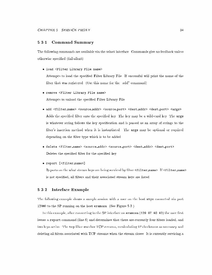
5.3.1 Command Summary
The following commands are available via the telnet interface. Commands give no feedback unless
otherwise speci�ed (fail-silent).
� load <Filter Library File name>
Attempts to load the speci�ed Filter Library File. If successful will print the name of the
�lter that was registered. (Use this name for the \add" command)
� remove <Filter Library File name>
Attempts to unload the speci�ed Filter Library File.
� add <filter name> <source addr> <source port> <dest addr> <dest port> <args>
Adds the speci�ed �lter onto the speci�ed key. The key may be a wild-card key. The args
is whatever string follows the key speci�cation and is passed as an array of strings to the
�lter's insertion method when it is instantiated. The args may be optional or required
depending on the �lter type which is to be added.
� delete <filter name> <source addr> <source port> <dest addr> <dest port>
Deletes the speci�ed �lter for the speci�ed key.
� report [<filter name>]
Reports on the what stream keys are being serviced by �lter <filter name>. If <filter name>
is not speci�ed, all �lters and their associated stream keys are listed.
5.3.2 Interface Example
The following example shows a sample session with a user on the host styx connected via port
12000 to the SP running on the host eramosa. (See Figure 5.3.)
In this example, after connecting to the SP interface on eramosa (129.97.40.42) the user �rst
issues a report command (line 6) and determines that there are currently four �lters loaded, and
two keys active. The tcp �lter watches TCP streams, recalculating IP checksums as necessary and
deleting all �lters associated with TCP streams when the stream closes. It is currently servicing a

CHAPTER 5. SERVICE PROXY 35
single stream 11.11.10.99 7 -> 11.11.10.10 1169. Note that the two hosts in this connection,
11.11.10.99 and 11.11.10.10 are being simulated on eramosa. The launcher �lter runs on
wild-card keys and adds �lters to new streams which match its wild-card key. As can be seen on
lines 9-10, it is watching 11.11.10.10 0 -> 0.0.0.0 0. It is currently applying tcp and wsize
�lters on matching streams. Before this example, the stream 11.11.10.99 7 -> 11.11.10.10
1169 was detected and the two �lters applied. The wsize �lter alters the TCP window size
(see Section 8.2.2 for a description) and is also servicing the only real stream 11.11.10.99 7 ->
11.11.10.10 1169. The rdrop �lter is currently loaded but is not applied to any streams. It is a
transparency-support �lter (see Section 8.1) that randomly drops packets with a given frequency.
The user decides to remove the wsize �lter and instead use an rdrop �lter with a drop rate
of 50%. Line 15 shows a well-formed add command for the rdrop �lter, where 50 is the additional
parameter. Note that the following report command (line 17) shows that the �lter has in fact
been loaded (see line 25). The delete command on line 27 is successful as the wsize �lter no
longer has any associated streams (line 34).
The �lters described above are all direction-insensitive and have the following priorities:
launcher - HIGHEST, tcp - HIGH, rdrop - LOW, wsize - LOWEST. Thus. when the report
command at line 17 was given, packets on the stream 11.11.10.99 7 -> 11.11.10.10 1169
would �rst be inspected by the tcp �lter, then the rdrop and wsize �lters. The packet would
then be modi�ed by the wsize �lter, followed respectively by the rdrop and tcp �lters. This
ordering prevents the tcp �lter from calculating the IP checksum before all changes to the packet
are made and allows the rdrop �lter to drop packets without regard to the changes made by the
wsize �lter.
This chapter has described the issues, design and interface of the Service Proxy used in Comma.
The following chapter follows the same format to explain the Comma Execution-Environment
Monitor.

CHAPTER 5. SERVICE PROXY 36
1 styx:~> telnet eramosa 12000
2 Trying 129.97.40.42...
3 Connected to eramosa.uwaterloo.ca.
4 Escape character is '^]'.
5
6 report
7 tcp
8 11.11.10.99 7 -> 11.11.10.10 1169
9 launcher
10 11.11.10.10 0 -> 0.0.0.0 0
11 wsize
12 11.11.10.99 7 -> 11.11.10.10 1169
13 rdrop
14
15 add rdrop 11.11.10.99 7 11.11.10.10 1169 50
16
17 report
18 tcp
19 11.11.10.99 7 -> 11.11.10.10 1169
20 launcher
21 11.11.10.10 0 -> 0.0.0.0 0
22 wsize
23 11.11.10.99 7 -> 11.11.10.10 1169
24 rdrop
25 11.11.10.10 1169 -> 11.11.10.99 7
26
27 delete wsize 11.11.10.99 7 11.11.10.10 1169
28
29 report
30 tcp
31 11.11.10.99 7 -> 11.11.10.10 1169
32 launcher
33 11.11.10.10 0 -> 0.0.0.0 0
34 wsize
35 rdrop
36 11.11.10.10 1169 -> 11.11.10.99 7
37
38 ^]
39 telnet> quit
40 Connection closed.
Figure 5.3: SP Interface Example

Chapter 6
Network Monitor
It is widely believed that the application-level solution to variable network QoS is to make ap-
plications adaptive to changes in the underlying network. Applications could then alter their
operation to reduce communication in times of low bandwidth. This allows the application to
continue operating, though the the user might perceive inferior service from the application at
that time.
This idea can be extended to data streams as well. If communication streams could be shaped
to the available QoS without compromising the operation of the distributed application, varying
QoS could be handled by the use of a proxy mechanism. Filters can then prioritize information
to be sent to the mobile so that in times of low QoS, minimal operation can continue and regular
operation resume in periods of high QoS. Such services are presented in Chapter 8.
In order to support such adaptability, it is necessary to obtain accurate information about the
state of the network. The Comma Execution Environment Monitor (EEM) allows clients (�lters
or distributed applications) to register interest in one or more metrics from one or more EEM
servers. EEM clients run as application threads that communicate with EEM servers on hosts in
which the application has registered an interest. EEM servers can run on any networked host,
and gather local network and machine statistics. The EEM server has been designed so that
it can access a wide and easily extensible variety of information sources on its local host. This
37

CHAPTER 6. NETWORK MONITOR 38
allows application designers to extend the EEM model so that clients can monitor environment
conditions of speci�c interest to them.
6.1 Issues
Network monitoringhas twomain components: a data-gathering component, and a data-dissemination
component. The data-gathering component either polls system metrics, or connects with other
components to query their knowledge bases. In order to pass this information on to interested
applications, some method of communicating that information is required.
The following areas of concern have led to the design of the existing EEM.
6.1.1 Data Sources
In order to e�ectively characterize the state of the network, a wide variety of environment measures
or metrics must be available to the application. There is still much debate on how to characterize
good and bad network performance. Since this is the case, it was decided not to limit the design
of the EEM to a single set of metrics, but to use a more modular approach where new measures
could be added to the monitor at a later date.
6.1.2 Generated Tra�c
An area of concern for network monitors is the amount of tra�c produced by client updates. In
resource-poor environments, such as wireless networks, the use of resources should be minimized.
In order to reduce network utilization, such as that caused by the individual message-per-
metric overhead of polling, we have centralized all data gathering on servers which monitor their
own local environment. Monitor servers have been made as portable as possible so that they can
be placed on any host on which a network data source, such as SNMP [5], exists. Monitor clients
connect with remote servers indicating what metrics interest them and at what point they wish
to be informed. The client will only receive messages from the server of the metrics which meet
those criteria, at the time speci�ed by the client: immediately for interrupt-style noti�cations, or

CHAPTER 6. NETWORK MONITOR 39
in a certain amount of time for periodic updates. Combined with a lean data-transfer protocol
between client and server, the tra�c generated is greatly reduced for monitor updates.
6.1.3 Noti�cation Method
One of the most important questions for a monitor designer is when and how the client should
be noti�ed about the state of the network. The three main options are: an interrupt approach,
where the client is noti�ed immediately about changes; a periodic approach, where the client is
noti�ed of changes at regular intervals; and allowing the client to poll the information sources
itself.
When a client wishes to be noti�ed of changes in its execution environment, it must �rst
indicate which metrics it is interested in and what values of the metric cause noti�cation.
The advantage of the interrupt-noti�cation approach is the speed and nature of the information
arrival. Since the message about the state of the network acts as an interrupt to the regular
operation of the application or �lter, important changes in the state of the network will be noticed
and handled early. The drawback comes from the complexity of programming for such changes.
A handling routine must be created for the metrics and the associated program must be able to
handle one or more interrupts.
Periodic client noti�cations allow for much less intrusive updates. Periodic noti�cation can
be done in the background and it is left to the program to decide when to look at the local copy
of the current network metrics. This leads to a much less complicated program, but important
changes may be missed until the program explicitly checks the stored values.
A more active approach is also available where the client queries the information sources
directly. This method has the advantage that queries of the data source are made only when
needed by the client. However, there are several disadvantages. Where more passive approaches
can hide the di�erences in query methods of di�erent data sources, the polling client must make
all such requests itself. Communication overhead is also greatly increased since di�erent metrics
must be queried separately, where both periodic and interrupt-style updates can include all related
information in a single message. Also, update-style messages will include only such variables as

CHAPTER 6. NETWORK MONITOR 40
have changed, reducing overhead further. A �nal consideration involves the synchronous nature of
polling. Unless a more complex threaded communication style is used by the client, polling leads
to pauses of execution while server requests are processed. This in unacceptable for real-time
operation of clients such as �lters.
A mixed approach was decided on for the EEM, where all three types of noti�cation would be
available. This has led to a complex server model, but the client now has the option of choosing
which method or combination of the three methods is most appropriate for its operation. When
the client initiates a monitor session, it can request interrupt-style as well as periodic noti�cation.
Functions are also available to poll the EEM server directly about individual variable.
6.2 Monitor Design
The Comma Execution-Environment Monitor (EEM) is a network- and computing-environment
report tool. EEM servers run on suitable hosts and gather information on local performance
metrics for local or remote clients. The EEM is con�gurable so that it can gather information
from any local information source, including user-written ones.
The EEM design has four main parts: the client functional library, which presents an abstrac-
tion of the services o�ered by the EEM; the server process, which accepts and services requests
from the clients; a client-supplied callback function, which is combined with an exception handler
for interrupt-style noti�cations; and a protected data area, which is used for periodic updates.
The architecture is shown in Figure 6.1.
To use the EEM, clients, which may be applications or SP �lters, call an initialization function
specifying the address of a callback function if interrupt-style noti�cation is desired. Initialization
also clears the protected data area and starts a second thread to handle communication with EEM
servers.
The client can then register an interest in network- and execution-environment metrics or
variables. The actual variables available at any EEM server will depend on the particular host,
but it is expected that at least the SNMP variables will be available. It is hoped that, eventually, a

CHAPTER 6. NETWORK MONITOR 41
InfoClient
Network Manager
Registration Serviceblock
Protecteddata area
Main Thread
Client Server
Connection Thread
comma_register(id,signature)
Application
comma_init(&handler)
Exceptionhandler
Figure 6.1: The Execution Environment Monitor (EEM) Architecture
standard set of metrics will be provided. However, the de�nition of a set of measures appropriate
to all applications is beyond the scope of this thesis.
To register interest in a variable, the client �rst creates a variable ID consisting of the variable
name and the host on which the variable will be measured. This is accompanied by a \signature",
consisting of a range within which values of the variable must fall for noti�cation to occur and a
method of noti�cation.
Applications may be noti�ed in one of two ways when an EEM �nds that a registered variable
falls within its requested range. The �rst is an interrupt-driven callback. If a noti�cation arrives
for a variable for which interrupt noti�cation was requested, the exception handler immediately
calls the callback function provided by the client on initialization. It is then up to the developer to
handle the informationpassed to the function. The second and less intrusive method of noti�cation
involves periodic silent updates to a protected data store. The application can query the data
store to determine whether a variable has changed or what the most up-to-date value is.
Whenever a client registers for a variable on an EEM server not already connected to the client,
the connection thread opens a connection to the new host, sends the new variable registration
information, and then receive-blocks until it receives an update from the server. When information
is received on this connection, the message is parsed by the exception handler and either a call to

CHAPTER 6. NETWORK MONITOR 42
the callback function is made or the common data area is updated.
The server initially waits for registrations from clients. Whenever it receives a request, it
updates its database, taking note of the requesting host and port number. The server then makes
periodic checks of the variables registered by all clients and compares them to the conditions
under which each client asked to be informed. If an interrupt-style variable has changed into the
desired range, a noti�cation message to the appropriate client is sent immediately. Otherwise, an
update containing all variables that fall within their requested range is sent to the appropriate
client once all variables have been checked. Polling is also supported by allowing for temporary
registrations which are immediately removed after the requested metric has been retrieved and
sent back to the client.
This simple and extensible approach provides applications with the network and execution-
environment metrics necessary for adaptation.
6.3 EEM Interface
This section describes the variables and interface functions available to EEM clients. A list of the
server variables currently available is given, most of which are retrieved from local SNMP servers.
The functional interface to the EEM is described in some detail since it was created as part of
this thesis for use with the Kati shell. Finally, a brief test program is described which uses the
EEM interface.
6.3.1 EEM Variables
The EEM server uses SNMP [5] as its main data source (see Table 6.1), but several other variables
are o�ered. These variables were found to be of use in earlier applications (see Table 6.2).
These variables are divided into three basic data types: integer, double, and string. In order to
deal with variables a union type was created called comma type t. The function comma id gettype
returns the type of the variable speci�ed in the comma id t as one of LONG, DOUBLE, or STRING.

CHAPTER 6. NETWORK MONITOR 43
sysDescr ipInReceives ifNumberssysObjectID ipInHdrErrors ifIndexsysUpTime ipInAddrErrors ifDescrsysContact ipForwDatagrams ifTypesysName ipInUnknownProtos ifMtusysLocation ipInDiscards ifSpeedsysServices ipInDelivers ifInOctets
ipOutRequests ifInUcastPktsudpInDatagrams ipOutDiscards ifInNUcastPktsudpNoPorts ipOutNoRoutes ifInDiscardsudpInErrors ipRoutingDiscard ifInErrors
ifInUnknownProtostcpRtoAlgorithm tcpRtoMin ifOutOctetstcpRtoMax tcpMaxConn ifOutUcastPktstcpActiveOpens tcpPassiveOpens ifOutNUcastPktstcpAttemptFails tcpEstabResets ifOutDiscardstcpCurrEstab tcpInSegs ifOutErrorstcpOutSegs tcpRetransSegs ifOutQLen
Table 6.1: SNMP Variables Supported by the EEM
variable descriptionnetLatency measure of the network latency from ping RTTs to the default routeravgInIPPkts average of incoming IP packets uni- or broadcast (from SNMP history)cpuLoadAvg cpuload average, as recorded by the local kernelethErrsAvg number of errors in ethernet frames received by hostethInAvg number of incoming ethernet frames received by hostethOutAvg number of outgoing ethernet frames sent by hostdeviceList string that lists the devices con�gured on hostbytes rx bytes received by the network device driverbytes tx bytes transmitted by the network device driver
Table 6.2: Additional EEM Variables

CHAPTER 6. NETWORK MONITOR 44
command descriptioncomma init: initialize comma structures & connect with
the local server.comma term: free all local structures & disconnect from
all servers currently in use.comma setcallback: sets default callback function for interrupt-
style callback noti�cation
Table 6.3: EEM Initialization and Termination Functions
6.3.2 EEM-Interface Functions
A client interface was developed for this thesis to be used by applications, SP �lters, and the Kati
shell. This interface was designed to give access to EEM server variables in a straightforward
manner, with minimal overhead. All interface functions begin with \comma ", followed by the
function they support. This scheme was used to identify variables related to Comma.
In order to receive environment metrics from the EEM, the application must �rst initialize its
interface, and then create some variable speci�cations to register. This is done by �lling in two
complementary data structures. The comma id t structure identi�es the variable type and EEM
server from which to receive the value. The comma attr t speci�es when the noti�cation is to
take place. It gives the noti�cation region and the evaluation criteria to determine if the variable
is currently within the bounds of interest. Once these two structures have been �lled in, they
are registered via the comma register() function. Updates will then arrive at the client, either
through callbacks to the speci�ed callback function or silently in the protected data area (PDA).
Variables stored in the PDA can be accessed through comma query functions. The client can use
query functions to retrieve values using the comma id t values used for the registration of that
variable. These EEM functions are brie y summarized in Tables 6.3 to 6.7.
Applications must �rst initialize internal data and other accounting structures hidden from the
application. The comma init function must be called before any other EEM-related functions. All
server connections are closed and data structures freed by a call to comma term. Currently, each
client has the option of using the periodic-update method with or without callback noti�cation.
If the comma setcallback function is called, all variables registered will be supplied to both the

CHAPTER 6. NETWORK MONITOR 45
command descriptioncomma id init: initializes id data structurecomma id setnum: sets id number of passed idcomma id setbyname: sets id number of passed id given var namecomma id setindex: sets id index of passed idcomma id setall: sets id number and index of passed idcomma id setserver: sets id server to given servercomma id isindexreqd: checks if given id requires an index valuecomma id gettype: returns the data type of the given idcomma id getname: returns the char* name of the given id
Table 6.4: EEM ID Functions
given callback function and the PDA. If no callback function is speci�ed, only the periodic-update
method will be used. These functions are summarized in Table 6.3.
In order to register a variable with a possibly remote EEM server, two data structures
must be �lled in using the given functions. The �rst structure, the comma id t type, spec-
i�es the variable type and EEM server location. This variable is used in the future for re-
trieving data stored in the PDA. Comma id init clears the variable id, while comma id setnum,
comma id setbyname, comma id setindex, and comma id setall can be used to specify the vari-
able type. The comma id setserver command can be used to retrieve a variable from a remote
EEM server. The comma id isindexreqd function returns true if an additional index value is
required for a variable, while the comma id gettype and comma id getname functions return the
type and name of the variable respectively. These functions are summarized in Table 6.4.
In order to specify the noti�cation parameters of a variable, an additional disposable data
structure must be �lled in. The comma attr init function clears the comma attr t structure. The
command description
comma attr init: (re)initializes attribute data structurecomma attr setlbound: sets lower bound for attrcomma attr setubound: sets upper bound for attrcomma attr setoperator: speci�es how bounds are interpreted
Table 6.5: EEM Attribute Functions

CHAPTER 6. NETWORK MONITOR 46
command descriptioncomma var register: given the id and attributes, registers with
the desired server for the particular variable.comma var deregister: given an id, de-registers that variable from
the appropriate server.comma var deregisterall: all current registrations with all servers are
de-registered (as above)
Table 6.6: EEM Register Functions
comma attr setlbound and comma attr setubound specify the bounds of the region of interest,
while the comma attr setoperator speci�es how these bounds are to be interpreted. These
functions are summarized in Table 6.5. Available unary operators are: COMMA GT, COMMA GTE,
COMMA LT, COMMA LTE, COMMA EQ, COMMA NEQ, and available binary operators are: COMMA IN,
COMMA OUT where GT = greater than, LT = less than, E/EQ = equal, and IN/OUT specify
inside and outside the bounds given. For unary operators, only the lower bound is used. Binary
operators require both the lower and upper bounds be speci�ed. Note that type checking is done
for string values so that only COMMA EQ, and COMMA NEQ are valid operators.
Once these two variable-description data structures have been speci�ed, the variable can then
be registered. The comma var register function connects to a new server (if required) and
makes the registration. Variables will then arrive at the client at a currently hard-coded interval
of roughly ten-seconds. Variables may be removed individually by using comma var deregister
command description
comma query getvalue: given an id, returns most recent value fromthe relevant server.
comma query isinrange: given an id, reports if most recent valuefrom relevant server was in requested range
comma query haschanged: given an id, reports if most recent valuefrom relevant server has changed since valuelast retrieved
comma query getvalue once: given an id and attribute, retrieves valuefrom server.
Table 6.7: EEM Query Functions

CHAPTER 6. NETWORK MONITOR 47
which will de-register the variable with the given id; comma var deregisterall de-registers all
variables currently in use. These functions are summarized in Table 6.6.
If the application wishes to gain information from the data area, the comma query functions
give a number of options for accessing the client's read-only store. Comma query getvalue simply
returns the most recent value of the variable of the given id. The comma query isinrange function
returns true if the variable is within the range of interest and comma query haschanged returns
true if the variable has changed since it was last read. If the application wishes only to query the
value of a single variable once, the comma query getvalue once returns the current value as soon
as the EEM server returns a reply. Note that this is a synchronous call which allows polling of an
EEM server. These functions are summarized in Table 6.7.
6.3.3 Interface Example
In order to illustrate the operation of the EEM and the use of the client interface, a sample
program is given in Figure 6.2.
This program begins by installing a signal for terminating the comma client (line 16). It then
initializes its interface (lines 18-22). It then �lls in a variable attribute structure so that the
interval of interest is the interior of [0,20] (lines 28-40). The program then �lls in an id structure
indicating that the variable of interest is SYS UPTIME (lines 46-52). Since no comma id setserver
call was made, the variable retrieved will be for the local host. The two structures are then
registered (lines 58-65). Following this, the PDA is polled at ten second intervals for two minutes
to see if the variable has changed. When the value changes, the new value is printed to the screen
(lines 71-81). This simple program could be used to check if or when a computer crashes during
some distributed operation.
This chapter has explored the issues, design and interface of the Comma EEM. The following
chapter completes the explanation of the support architecture used in this thesis with a discussion
of the Kati shell. Kati provides a interface to the operation of both the SP and EEM to allow
external control of the �lters running on the SP, where previously it was the responsibility of the
application to control their own �lters.

CHAPTER 6. NETWORK MONITOR 48
1 /*
2 * Sample EEM Client code
3 */
4
5 comma_id_t id;
6 comma_attr_t attr;
7 int lbound, ubound;
8 comma_type_t new_value;
9
10 int rc;
11
12 /*
13 * Do the initialization...
14 */
15
16 signal(SIGINT, (void*)comma_term);
17
18 rc = comma_init();
19 if( rc != COMMA_OK ) {
20 comma_perror( "comma_init" );
21 exit( 1 );
22 }
23
24 /*
25 * Fill in the attributes
26 */
27
28 rc = comma_attr_init( &attr );
29 if( rc != COMMA_OK ) {
30 comma_perror("attr_init");
31 exit( 1 );
32 }
33 lbound = 0;
34 comma_attr_setlbound( &attr,
35 &lbound, sizeof( lbound ) );
36 ubound = 20;
37 comma_attr_setubound( &attr,
38 &ubound, sizeof( ubound ) );
39 comma_attr_setoperator( &attr,
40 COMMA_IN );
41
42 /*
43 * ...and the ID
44 */
45
46 rc = comma_id_init( &id );
47
48 rc = comma_id_setall( &id,
49 COMMA_SYSUPTIME, 0 );
50 if( rc != COMMA_OK ) {
51 comma_perror( "setserver" );
52 }
53
54 /*
55 * Register the variable
56 */
57
58 rc = comma_var_register( &id, &attr );
59 if( rc != COMMA_OK ) {
60 comma_perror( "var_register" );
61 exit( 1 );
62 }
63 else {
64 printf("main: register OK\n");
65 }
66
67 /*
68 * Continually read from static store
69 */
70
71 for(int i=0;i<12;i++) {
72 if ( comma_query_haschanged(&id) ) {
73 rc = comma_query_getvalue(&id,
74 &new_value);
75 printf("main: %s is now %ld\n",
76 comma_id_getname(&id),
77 new_value.u.val_long );
78 } else
79 printf("main: %s: no change\n",
80 comma_id_getname(&id));
81 sleep(10);
82 }
Figure 6.2: Sample Code

Chapter 7
Transparent Service Control
When using localized systems such as the SP to modify communication streams, the system must
be noti�ed as to which services should be applied to which streams. Not all streams will bene�t
from all services. Indeed, some services may disrupt communication or corrupt the data being
sent. Methods are needed to control multi-level �lters which can vary their operation depending
on external conditions.
The two methods of control used in previous proxy systems are direct application control
and internal adaptive control. Application control requires the application to assign, remove,
and control the operation of stream �lters. Adaptive control allows �lters to modify their own
operation depending on the conditions of the network. Services which use this type of control
are either installed once for all streams or are applied by an application and left to run on the
speci�ed streams.
These types of �lter control are not su�cient for all applications. Legacy applications, for
instance, cannot communicate with the proxy in order to request or control �lter services. For
this reason, an alternative type of �lter control is proposed which allows users to request services
on behalf of an applications. This type of control can also be useful if the user knows something
that neither the application nor the network monitor would know. For instance, the user may
wish to give a certain communication stream more priority, or may be about to turn the computer
49

CHAPTER 7. TRANSPARENT SERVICE CONTROL 50
o�. Since this type of control is transparent to both the application and network, it has been
named transparent service control.
This chapter begins with a discussion of service-proxy control methods in Section 7.1. Sec-
tion 7.2 covers the design of Kati, while Section 7.3 gives a brief overview of its operation. The
chapter ends in Section 7.4 with an example of Kati's use which is analogous to the example given
in Section 5.4.
7.1 Control Methods
In order to associate �lter services with communication streams, some method of communicating
the needs of an application to the service proxy is required. There are three possible methods of
control.
� Direct Application Control. This would be most appropriate for services which need to be
running for correct operation of the application. It is up to the application to communicate
with the SP to add, remove, and control services to improve application performance.
� Adaptive to QoS. This applies to services which have a level of self-control associated with
them. Compression �lters can make use of network metrics to determine the amount of
compression required to get the most vital information to the mobile and adjust their own
operation accordingly. Filters of this sort can be added at the beginning by users or appli-
cations and can adjust their operation over time.
� User Control. Proposed here, this category allows services to be added, removed and con-
trolled by a remote third party (that is, neither the application nor the �lter).
Application control centralizes all operations in the application itself. This control method
has been the traditional method in proxy systems to this point, since applications have internal
knowledge of their execution with which to guide their operation. Combined with the information
gained from the use of a network monitor, this can be su�cient for making service control optimal
for the application.
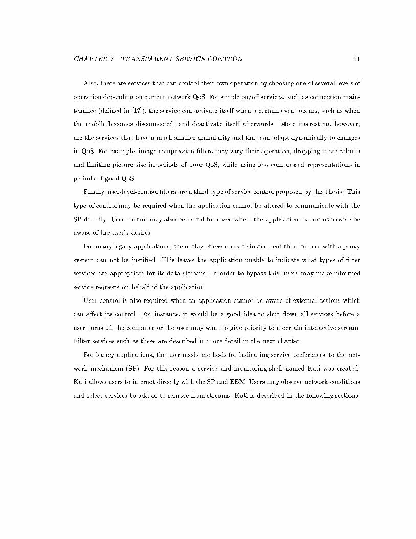
CHAPTER 7. TRANSPARENT SERVICE CONTROL 51
Also, there are services that can control their own operation by choosing one of several levels of
operation depending on current network QoS. For simple on/o� services, such as connection main-
tenance (de�ned in [17]), the service can activate itself when a certain event occurs, such as when
the mobile becomes disconnected, and deactivate itself afterwards. More interesting, however,
are the services that have a much smaller granularity and that can adapt dynamically to changes
in QoS. For example, image-compression �lters may vary their operation, dropping more colours
and limiting picture size in periods of poor QoS, while using less compressed representations in
periods of good QoS.
Finally, user-level-control �lters are a third type of service control proposed by this thesis. This
type of control may be required when the application cannot be altered to communicate with the
SP directly. User control may also be useful for cases where the application cannot otherwise be
aware of the user's desires.
For many legacy applications, the outlay of resources to instrument them for use with a proxy
system can not be justi�ed. This leaves the application unable to indicate what types of �lter
services are appropriate for its data streams. In order to bypass this, users may make informed
service requests on behalf of the application.
User control is also required when an application cannot be aware of external actions which
can a�ect its control. For instance, it would be a good idea to shut down all services before a
user turns o� the computer or the user may want to give priority to a certain interactive stream.
Filter services such as these are described in more detail in the next chapter.
For legacy applications, the user needs methods for indicating service preferences to the net-
work mechanism (SP). For this reason a service and monitoring shell named Kati was created.
Kati allows users to interact directly with the SP and EEM. Users may observe network conditions
and select services to add or to remove from streams. Kati is described in the following sections.

CHAPTER 7. TRANSPARENT SERVICE CONTROL 52
7.2 Kati Overview
Kati provides a shell into the operation and services o�ered by Comma. One of its purposes is
to monitor the environment in which its local mobile applications are running. First, it keeps
track of communication streams passing through the local SP. By connecting with an SP, Kati
can gather information such as what streams are currently passing through it, the services o�ered
to each stream, and the current status of each stream. It can also tell what �lters are available at
this SP and which �lters have been associated with which wild-card keys. Second, it monitors the
environment metrics on mobile and �xed hosts. Kati connects with EEM servers and can display
any variable available on those servers.
Kati can also be used as an intervention tool. Kati allows users to associate and disassociate
�lters with keys. This is especially important for legacy applications since these applications
cannot request services on their own behalf. This allows protocol-enhancing services to be added,
or if the type and format of the communication used by the application are known, application-
speci�c protocols that make use of this knowledge can be created. Graceful degradation or lossy
compression can then be used intelligently in the face of low or varying QoS on the wireless
network.
Kati is divided into two main parts, corresponding to the two server types of the proxy system.
The main shell deals with the operation of the SP. It displays the streams currently passing
through the SP and the services associated with those streams. The user may add or remove
services manually. The secondary \Xnetload" shell deals with the EEM. The user may register
any variable available to the EEM, all of which will be displayed in the metric display window. A
numeric measure may be selected for graphing in the window to the left of the main metric area.
The operation and implementation of Kati are explained in the following section.
7.3 Kati Design
Kati implements a graphical user interface which provides a shell into the operation of the Comma
SP and EEM. For this reason, the shell was divided into two windows. The main window provides

CHAPTER 7. TRANSPARENT SERVICE CONTROL 53
Selected Stream Key Add Service Remove ServiceStream Key
Start Xnetload Service List
Stream ListAssociated Filters
Exit
Figure 7.1: Main Kati Window
monitor and control functionality related to the SP. The Xnetload window provides the user with
the ability to monitor environment metrics provided by the EEM.
The main Kati shell interfaces with the local SP using the interface described below. The
interface opens short-lived connections to port 12000 to issue periodic report commands. The
information retrieved is displayed in the main window. Using the main window, the user may also
add and remove services. Once the user has indicated what the services are to be, this information
is used to create well-formed add and remove commands to be sent to the SP.
The main shell is divided into two regions (see Figure 7.1). The right-hand side is dominated
by the Stream List. This area lists all streams that are currently passing through the service
proxy. Each stream has two associated keys (one for each direction). However, in order to reduce
space, only one of these keys is used since all �lters are currently bi-directional (methods applied
on both directional stream keys). To the right of each stream is a list of the �lters associated with
it.
The left-hand side of the main window contains the service-display and -control functions.
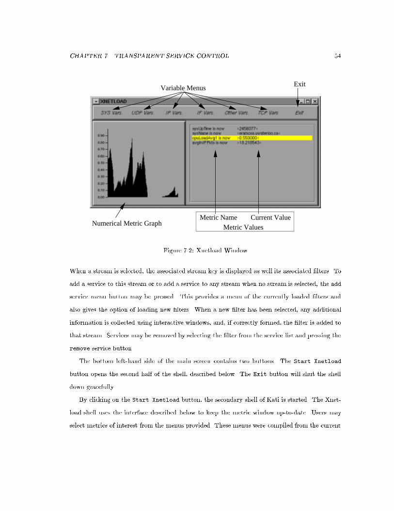
CHAPTER 7. TRANSPARENT SERVICE CONTROL 54
Current ValueMetric Values
Exit
Numerical Metric Graph
Variable Menus
Metric Name
Figure 7.2: Xnetload Window
When a stream is selected, the associated stream key is displayed as well its associated �lters. To
add a service to this stream or to add a service to any stream when no stream is selected, the add
service menu button may be pressed. This provides a menu of the currently loaded �lters and
also gives the option of loading new �lters. When a new �lter has been selected, any additional
information is collected using interactive windows, and, if correctly formed, the �lter is added to
that stream. Services may be removed by selecting the �lter from the service list and pressing the
remove service button.
The bottom left-hand side of the main screen contains two buttons. The Start Xnetload
button opens the second half of the shell, described below. The Exit button will shut the shell
down gracefully.
By clicking on the Start Xnetload button, the secondary shell of Kati is started. The Xnet-
load shell uses the interface described below to keep the metric window up-to-date. Users may
select metrics of interest from the menus provided. These menus were compiled from the current

CHAPTER 7. TRANSPARENT SERVICE CONTROL 55
list of variables available (See Tables 6.1 and 6.2). The Xnetload client then polls the protected
data area until new information arrives, after which it is displayed in the metric window. If a
numeric variable is selected, the data will be graphed in the left hand portion of the window.
The Xnetload shell displays information related to the local EEM (see Figure 7.2). The
variables currently available can be selected from the menu headings at the top of the Xnetload
window. Once a variable has been registered, future updates from the EEM server will be re ected
in the metric-value window. a numerical metric may be graphed in the left hand side of the screen
by selecting the metric in the browser window. Future updates will be placed in the metric-value
window and mirrored in the accompanying graph if appropriate.
Kati was developed using the Xforms Library created by T.C. Zhao and Mark Overmars [31].
This library provides a graphical-user-interface-creation toolkit for use with X. Run-time schedul-
ing features of Xforms are used to implement polling of the SP and EEM.
7.4 Example
Note that this example is analogous to that given in Section 5.4. In order to illustrate the use of
Kati, consider the situation in which an uninstrumented application is running on the mobile and
communicating with the wired network. The user wishes to know if a new service should be added
to improve the performance of this application. The user �rst starts Kati on the mobile and sees
the window shown in Figure 7.1. This screen indicates that there are currently two keys in the
SP stream registry, one of which is a wild-card key associated with a launcher �lter, and the
other is associated with tcp and wsize �lters. When the Add Service button is pressed with the
11.11.10.99.7 -> 11.11.10.10.1169 key highlighted, the available �lters are tcp, launcher,
wsize and rdrop.
In order to determine the current state of the network, the user opens the Xnetload window,
registers a few variables, and leaves the cpuload of the router to be graphed for a while. A few
minutes later, the window shown in Figure 7.2 has appeared
The user then determines determines that a new �lter name rdrop should be added and the

CHAPTER 7. TRANSPARENT SERVICE CONTROL 56
Figure 7.3: Adding a Service from Kati
wsize �lter should be removed. The user selects the stream (which is currently the only non-wild-
carded service in the stream list) presses the Add Service button, and selects rdrop. By entering
the required parameter 50 (shown in Figure 7.3), the service is added to the stream and the user
can return to reviewing the performance of the stream (see Figure 7.4). While the stream is still
highlighted, by selecting the wsize �lter in the service list window, and pressing the Remove
Service button, the �lter will be removed from this stream.
This ends the section involved with the architecture used for the support and control of general-
purpose stream-modi�cation �lters. The following chapter explores these �lters, discussing their
types and uses. The support �lters used to transparently support user-level control are discussed
in detail.
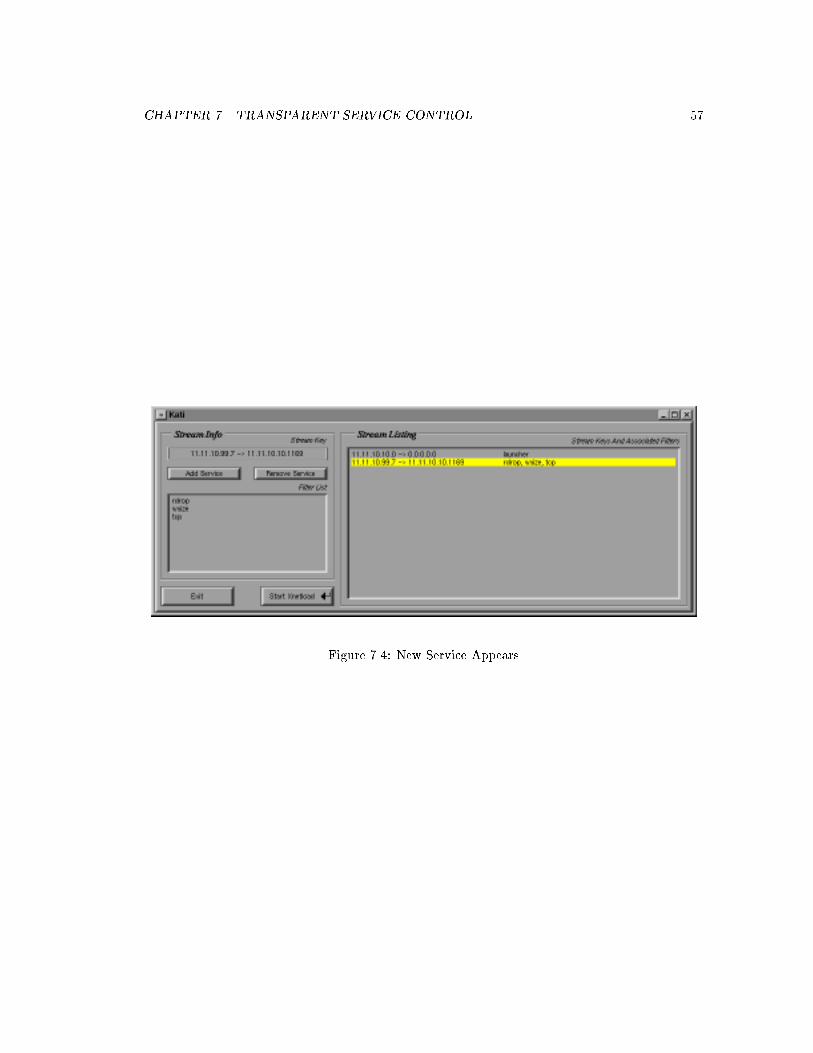
CHAPTER 7. TRANSPARENT SERVICE CONTROL 57
Figure 7.4: New Service Appears

Chapter 8
Stream Services
With the ability to assign �lters to the streams of legacy applications, the question then becomes:
what services are appropriate for these applications? Since their internal operation cannot be
modi�ed to handle changes in communication, some method is required whereby the underlying
data can be changed without interfering with the operation of the application or the underlying
protocols.
This chapter describes a new class of �lter called the transparency-support �lter. These
protocol-level �lters provide the detailed manipulations of packet headers to allow for transpar-
ent end-to-end delivery of manipulated data. Application-level services may use these �lters to
manipulate stream data without interfering with the operation of the distributed application.
This chapter begins with a discussion of transparency-support �lters in Section 8.1. A �lter
for supporting transparent data manipulations in TCP is presented and two examples of its use
are described.
The chapter continues with an overview of two other types of �lters, protocol and data-
manipulation �lters. Often, the parameters of a protocol can be manipulated to elicit behaviour
not originally planned by the protocol designers, without interfering with end-to-end semantics.
Protocol-level �lters are described in Section 8.2.
The second type of �lter manipulates application data. In this class, data within the com-
58

CHAPTER 8. STREAM SERVICES 59
munication stream is altered in a manner compatible with the receiver. Usually, the amount of
data sent is reduced by dropping or compressing data before sending it over the wireless network.
With the advent of the transparency-support �lters, this class of �lters can now be applied to
legacy applications. Application-level data �lters are described in Section 8.3.
8.1 Transparency-Support Filters
The goal of transparency-support �lters is to allow application-level �lters to modify packet data
without the sender or receiver realizing that such changes have been made. In order to accomplish
this, the packets themselves must be modi�ed at the proxy to give di�erent protocol views to the
two endpoints. To the sender, it must appear that all the data that was sent arrives as usual at
the receiver. Similarly, the receiver must believe that all data that was sent is arriving. The fact
that the proxy is actually altering the data in some way is to be hidden.
The method for accomplishing this lies in modi�cations of the protocol portion of the packets
being sent. The following sections describe the issues inherent in this kind of modi�cation and
how it has been applied to TCP. Two �lters which use this type of modi�cation were implemented
and tested. The packet-dropping �lter supports the dropping of packets and the required proto-
col manipulations to maintain protocol semantics. The compression �lter works similarly, only
assuming a more random data-size change. The design and operation of the TCP Transparency
Support Filter (TTSF) is explained in the following sub-sections.
8.1.1 Issues
In order to support a variety of data-manipulation �lter services transparently, a method for
transparent modi�cation of lower-level protocols is required. Problems arise if protocol-speci�c
information in the packet headers becomes invalid as a result of the change in the data payload.
In order to handle this change, the data stream must be repacketized. Repacketization can be
done in one of two ways. Previous proxy servers have split the stream between sender and receiver
at the proxy, resulting in two separately managed streams.

CHAPTER 8. STREAM SERVICES 60
Split-stream methods such as that proposed by Zenel [30] provide �lters with a data stream
from one end of the split stream to modify, after which the modi�ed data stream is forwarded on
the second. Repacketization is provided automatically by the interface with the outgoing stream.
There are two drawbacks to this approach. Since �lters are provided with data streams and not
packets, the modi�cations that �lters are capable of making are limited to the application-data
level. It will be argued in Section 8.2 that additional protocol-level services can be provided as
long as �lters have access to the packet headers of a stream. The other drawback is that the split
stream inherently violates the end-to-end semantics of the original stream. (See Section 5.1.2 for
a discussion of the end-to-end problem.)
The other option for stream repacketization is to change the packet headers to re ect the new
packet contents. In this scheme, a low-level �lter makes intelligent header modi�cations after all
other �lter manipulations are made and before the packet is reinjected onto the network. Low-
level header manipulations are made to provide both ends of the connection with a separate but
consistent view of the connection. This novel scheme allows changes to be made to the application
data without the knowledge of the distributed application. Since this scheme relies on the receiver
to acknowledge packets, the end-to-end problem is solved as described in Section 8.2.2. As a proof
of concept, such a transparency-support �lter was implemented for TCP. The resulting �lter is
explained in the following sections.
8.1.2 The TCP-Transparency-Support Filter (TTSF)
In order to illustrate this approach with a proof of concept, a transparency-support �lter for TCP
was implemented.
In order to support transparent data modi�cation, all protocol-header �elds which change with
a change in the data must be identi�ed and set to new values appropriate for the new payload.
For TCP, these �elds include the sequence number, acknowledgment number and checksum. (See
Figure 8.1 for a diagram of the complete TCP protocol header.) Note that in order to handle
changes in packet-data length the Total Length �eld of the IP header must change as well. This
is currently handled by a separate tcp �lter which also modi�es the IP checksum.

CHAPTER 8. STREAM SERVICES 61
0 1 2 3
0 1 2 3 4 5 6 7 8 9 0 1 2 3 4 5 6 7 8 9 0 1 2 3 4 5 6 7 8 9 0 1
+-+-+-+-+-+-+-+-+-+-+-+-+-+-+-+-+-+-+-+-+-+-+-+-+-+-+-+-+-+-+-+-+
| Source Port | Destination Port |
+-+-+-+-+-+-+-+-+-+-+-+-+-+-+-+-+-+-+-+-+-+-+-+-+-+-+-+-+-+-+-+-+
| Sequence Number |
+-+-+-+-+-+-+-+-+-+-+-+-+-+-+-+-+-+-+-+-+-+-+-+-+-+-+-+-+-+-+-+-+
| Acknowledgment Number |
+-+-+-+-+-+-+-+-+-+-+-+-+-+-+-+-+-+-+-+-+-+-+-+-+-+-+-+-+-+-+-+-+
| Data | |U|A|P|R|S|F| |
| Offset| Reserved |R|C|S|S|Y|I| Window |
| | |G|K|H|T|N|N| |
+-+-+-+-+-+-+-+-+-+-+-+-+-+-+-+-+-+-+-+-+-+-+-+-+-+-+-+-+-+-+-+-+
| Checksum | Urgent Pointer |
+-+-+-+-+-+-+-+-+-+-+-+-+-+-+-+-+-+-+-+-+-+-+-+-+-+-+-+-+-+-+-+-+
| Options | Padding |
+-+-+-+-+-+-+-+-+-+-+-+-+-+-+-+-+-+-+-+-+-+-+-+-+-+-+-+-+-+-+-+-+
| data |
+-+-+-+-+-+-+-+-+-+-+-+-+-+-+-+-+-+-+-+-+-+-+-+-+-+-+-+-+-+-+-+-+
Figure 8.1: TCP Header
1. Sequence Number (SEQ). In order to uniquely identify every packet of a stream, an initial
sequence number is determined when a new TCP stream is created. The �rst packet is
given this sequence number. The next packet is given a sequence number of the initial
sequence number plus the length of the initial packet. Thus every byte of the packet is, in
e�ect, numbered. For this reason, changes in packet size must be accompanied by changes
in sequence number. For example, if data is being compressed, sequence numbers arriving
from the sender would be much higher than the receiver expects. The TTSF must thus set
the sequence number to the correct value expected by the receiver.
2. Acknowledgment Number (ACK). The acknowledgment number is sent by the receiver upon
receipt of a packet. The acknowledgment number corresponds to the sequence number of the
packet the receiver expects to receive next. Since the receiver has been receiving sequence
numbers smaller than those sent by the sender, the proxy must convert the acknowledgment
number to the value the sender would expect for the acknowledgment number being sent.

CHAPTER 8. STREAM SERVICES 62
3. Checksum. Since the packet content has changed, the last modi�cation that must be made
is to recalculate the checksum so the packet it not discarded by the network.
The following section gives the algorithmand issues surrounding the use of the TCP-transparency-
support �lters.
8.1.3 TTSF Design
The idea behind the TCP-transparency-support �lter (TTSF) is to manipulate the acknowledg-
ment and sequence numbers of TCP so that the views of each end of the connection are consistent
individually, but can in fact be quite di�erent. Where the sender may believe it has sent 1000
bytes of information, the receiver may be quite sure it has received all 500 bytes that were trans-
mitted. The �lter has altered the data and acknowledgement packets so that each side of the
connection has a di�erent but related view of the stream.
The TTSF provides the following services to �lters of lower priority.
� Massage Packet Headers. The TTSF corrects the SEQ and ACK �elds of the TCP header
so that the receiver will accept the modi�ed stream and the sender will send normally. The
TCP checksum is also recalculated.
� Packet Bu�ering. (future) Packets which arrive at the SP early will be bu�ered by the
TTSF until the previous packets have all been processed. At that time, the packet will be
re-injected into the top of the in �lter queue.
� Packet Caching. (future) Packets already sent to the receiver are cached at the TTSF in
case the packet is lost. Such packets are retransmitted if an internal timeout occurs, or a
duplicate packet arrives at the SP. This mechanism is similar to that used by Snoop [3].
� Dropped Acknowledgment. If a data �lter drops a packet and all packets to the receiver have
been acknowledged, an immediate acknowledgment is passed back to the sender. Otherwise
the related acknowledgment will be piggybacked on the next appropriate packet.

CHAPTER 8. STREAM SERVICES 63
� On packet arrival from sender :
1. If the packet is the next packet expected,
(a) Allow other �lters to change data contents,
(b) Set offset := offset + change in size of packet,
(c) Set packet SEQ := current SEQ + offset,
(d) Add (current SEQ+size, packet SEQ+modi�ed size) to assoc table,
(e) If the packet has been dropped (size of packet == 0),
i. Send immediate acknowledgment to sender if all previous packets have beenacknowledged,
Otherwise,
i. Cache modi�ed packet for possible retransmission,
ii. Send packet to receiver,
(f) Process next packet similarly if it is in the packet bu�er.
2. If the packet is a retransmission,
(a) If packet is already acknowledged,
i. Resend acknowledgment,
Otherwise,
i. Resend cached packet to receiver.
3. Otherwise the packet has arrived early, soBu�er packet for future processing.
� On packet arrival from receiver :
1. Set packet ACK := lookup (?,packet ACK) on assoc table, and
2. Forward packet on to sender.
Figure 8.2: Transparent TCP-Filter Algorithm
� Acknowledgment Replay. (future) If the acknowledgment bound to the sender is lost, re-
transmissions from the sender are acknowledged immediately.
The algorithm for transparent TCP �ltering is given in Figure 8.2. Note that this �lter is only
accounting for data passing in one direction (to the receiver). For data passing in both directions,
a symmetric algorithm must be run in the opposite direction.
The algorithm uses two data structures. The offset is an integer that records the total
di�erence between the sequence numbers (SEQ) that arrive from the sender and those that are
sent to the receiver. This number is initialized to the expected 0, but is usually negative since

CHAPTER 8. STREAM SERVICES 64
data is most often compressed. The assoc table is an association table that stores tuples of the
form (a,b). Tuples may be added, or one of the two values of a or b can be looked up if the
other value is known. The lookup of (a,?) returns the value of b from the stored tuple (a,b).
Similarly a lookup of (?,b) returns the value of a from the stored tuple (a,b). If more than one
matching tuple exists, the highest of the matching values among those tuples is returned.
The algorithm begins by determining if the packet is a data or acknowledgment packet. Data
packets which have arrived in order are processed by data �lters �rst so that the change in data
size may be determined. This size di�erence is added to the di�erence so far so that the total
\skew" between the sending and receiving SEQ can be determined. The altered SEQ is stored in
the packet. The altered and \actual" SEQ are used to calculate the expected acknowledgment
numbers, and are stored together in the association table. This will allow the corresponding
acknowledgment to be retrieved when the acknowledgment for the altered packet arrives from the
receiver.
If the packet has been dropped, an immediate acknowledgment can be returned as long as
there are no packets unacknowledged on the receiver side. If there were outstanding packets,
an acknowledgment would inadvertently cover those packets as well. If the packet still contains
some data, it is cached for possible retransmission and then sent on to the receiver. The bu�ered
\early" packets are then inspected. If the next packet after the one just processed has already
arrived, it is processed in the same manner.
Data packets which have a SEQ less than the expected packet must be a retransmission. This
can signal one of two things. Either the packet was previously acknowledged and the acknowl-
edgment was lost, or the packet did not reach the receiver. If the acknowledgment was lost, the
acknowledgement can be resent to the sender. If the packet was lost, the corresponding cached
packet can be resent to the receiver.
Data packets with a SEQ greater than that expected must be out of order and need to be
bu�ered until the earlier packets arrive and are processed. The reason they cannot be processed
immediately is that the compression of previous packets needs to be included in the calculation
of the current packet's altered SEQ.

CHAPTER 8. STREAM SERVICES 65
In the return direction, acknowledgments are simply changed to re ect what the acknowledg-
ment would have been had the entire packet arrived at the receiver.
8.1.4 TCP-Speci�c Issues
There are, unfortunately, some special cases that had to be dealt with in TCP. For instance, when
determining what the SEQ for the next packet should be, it is not simply the current SEQ plus
the size of the packet. Two packets that are used in connection maintenance create special cases.
The SYN packet is used when creating a new stream and the FIN packet is used when closing a
connection. These packets are identi�ed by the ags set in the TCP header. Each of these packets
act as if they were one byte longer than the actual packet size and this must be factored into the
\expected packet" algorithm.
Another problem with SEQs is the phenomenon known as roll-over. Since SEQs are stored as
32-bit integers, there is a maximum SEQ beyond which it cannot increase. To deal with this, the
SEQ \rolls over" and begins again at 0. Roll-over needs to be handled in the algorithm in two
ways. The association table needs to know the original sequence number so that it can correctly
determine when roll-over has occurred. It must also be able to discard old tuples so that they
do not con ict with SEQs that roll-over. The second modi�cation to the algorithm involves the
o�set around the roll-over. The calculation of the modi�ed packet SEQ must take roll-over into
account.
Finally there is one more problem with SEQs, retransmissions and adaptive services. When a
packet is retransmitted, the conditions of the network may have changed from when it was �rst
sent. If this change is signi�cant, adaptive �lters may be treating packets di�erently the second
time the packet is processed, resulting in a di�erent packet size from the original transmission.
However, packets have used the original packet size in their calculations for SEQ and ACK num-
bers. The solution chosen, but not yet implemented, is to bu�er sent packets at the proxy until
they have been acknowledged at the receiver, resulting in a Snoop-like retransmission scheme.
The bu�ering and caching scheme to purge old packets has been left for future work.
A problem related to these transparent modi�cations has to do with the e�ect they have on

CHAPTER 8. STREAM SERVICES 66
the receive window (see Section 2.2). Though the data �lters may be changing the size of data
sent to the receiver, the receive window is left untouched. This gives a false impression to the
sender of the amount of data it can send. If the services at the SP reduce the data size, more
data could be sent; if the SP increased the data size (not a very desirable condition), the sender
may accidentally swamp the receiver. There are several possible changes that could be made to
the window size, such as scaling it to meet expected compression rates, but this has been left for
future work. The proxy should however keep track of the receive window size and be sure that
too much data is not sent.
To give some example of the use of the transparency-support �lter, consider the following
two examples. One �lter drops packets, while the another compresses them. Both �lters use the
transparency-support �lter to make it appear to both ends of the connection that all packets are
arriving and being acknowledged normally.
8.1.5 Packet-Dropping Example
One of the potential uses of the transparency-support �lter would be to support a reduction
in network utilization through the use of a packet-dropping �lter. Such �lters can be used for
applications which have time-sensitive data, such as audio players. If packets which were already
out-of-date arrived at the proxy, they could be discarded to reduce usage of the wireless network.
An example of the communication that would happen with such a �lter is given in Figure 8.2.
In this example packets are dropped in a random pattern. Discards are indicated by a solid circle
on the proxy's execution line. This example was chosen for its utility in analysis of the TTSF.
The points of interest noted in the �gure are explained below.
i) When the �rst packet arrives at the proxy, the drop �lter determines (through some internal
mechanism) that it should be dropped. Since there are no outstanding packets unacknowl-
edged to the wireless receiver, it can be acknowledged immediately. This scheme allows the
send window to open further so more data can be sent.
ii) At this point, the �rst packet has arrived from the receiver's point of view. Since the packet

CHAPTER 8. STREAM SERVICES 67
ii
1:2(1)
5:6(1)
7:8(1)
8:9(1)
9:10(1)
6:7(1)
4:5(1)
0:1(1)
3:4(1)
2:3(1)
Ack 1
Ack 2
Ack 3
Ack 4
Ack 7
Ack 9
Ack 10
Ack 3
Ack 4
Ack 5
Ack 1
0:1(1)
1:2(1)
2:3(1)
4:5(1)
3:4(1)
iv
Wired Proxy Wireless
i
iii
Current Packet Dropped
9:10(1) Sending Seqence Number 9,Next Seqeunce Number 10,Packet Size = 1 byte.
Now Expecting SEQ 5.Ack 5
Ack 2
Ack 3
Figure 8.3: Packet Dropping Example

CHAPTER 8. STREAM SERVICES 68
had a SEQ of 0 and a data size of 1, the acknowledgment indicates that it is ready to receive
the packet with SEQ 1. This acknowledgment is converted at the proxy to also cover the
two dropped packets (offset of -2) and thus the association table will give an ACK of 3.
iii) Another acknowledgment has now reached the proxy which has just dropped two consecutive
packets. Since there are currently no unacknowledged packets en route to the receiver, the
latest packet can now be acknowledged with an ACK of 7.
iv) Another case similar to (iii), where the acknowledgment for the dropped packet can be pig-
gybacked on the acknowledgment coming from the sender.
As can be seen, the sequence numbers at the receiver are consistent with the data that arrives.
At the sender, the acknowledgments seem to arrive as expected, as if all the packets had safely
arrived at the receiver.
8.1.6 Packet-Compression Example
Another use of the transparency-support �lter would be to support a data-compression �lter
that reduces the size of packets passing to the wireless receiver. This type of �lter would be
useful for applications such as graphics browsers. Pictures being transfered to a mobile could be
compressed at the proxy to be smaller, have fewer colours, etc. The corresponding reduction in
network utilization would decrease transfer time.
An example of the communication for such a �lter is given in Figure 8.3. In this example,
packet sizes are cut in half by the compression �lter at the proxy. The points of interest noted in
the �gure are explained below.
i) When the �rst packet arrives at the proxy, the data �lter reduces the packet size from two to
one data units. When the receiver acknowledges the remaining one data unit, the proxy
converts the acknowledgment to cover both data units that arrived at the proxy.
ii) One of the services that can be accomplished at the proxy is to retransmit packets which
appear to have been lost. At this point, a retransmission �lter determines that the packet
2:3(1) en-route to the receiver has been lost and should be resent from its cache.

CHAPTER 8. STREAM SERVICES 69
i
8:10(2)
6:8(2)
4:6(2)
0:2(2)
2:4(2)
8:10(2)
0:1(1)
1:2(1)
4:5(1)
3:4(1)
2:3(1)
2:3(1)
Ack 1
Ack 2
Ack 4
Ack 3
Ack 5
Ack 2
Ack 8
Ack 10
Ack 10
Ack 4
ii
Wired Proxy Wireless
8:10(2) Sending Sequence Number 8,Next Sequence Number 10,Paket Size = 2 Data Units.
Ack 5 Now Expecting SEQ 5
iii
Figure 8.4: Packet Compression Example

CHAPTER 8. STREAM SERVICES 70
iii) In this case, the acknowledgment from the proxy did not reach the sender. Since acknowl-
edgments from the receiver are stored, the sender can be immediately acknowledged at the
proxy instead of waiting for the receiver to do it.
Note once again that there are two separate views of the connection, both of which are in-
ternally consistent. The sender sees that all data is reaching the receiver, while the receiver sees
that all data seems to be arriving as expected. The fact that the data being sent is not the same
data as that received is known only by the proxy.
This section has presented a new class of �lter called transparency support �lters. These
�lters allow other data-manipulation �lters to arbitrarily modify packet data without violating
the protocol semantics. These �lters are of special interest to legacy applications which cannot
otherwise have their data streams modi�ed by the proxy system provided here.
8.2 Protocol Tuning
One of the main problems that wireless applications must deal with is the legacy of wired network
protocols. These protocols were designed with wired QoS characteristics in mind and may not
work well in the wireless environment. Wireless networks generally have lower throughput, more
transmission errors, and higher delay. When wired protocols are used over wireless networks, they
misinterpret the causes of the lower QoS and perform poorly.
In order to improve this situation, wired protocols can be tuned to handle the di�erent QoS
of wireless networks. Also, additional services that may be of use in the wireless environment
can be incorporated into the modi�ed protocol. In order to do this, an intimate knowledge of
the protocol is required and there must be su�cient exibility in the protocol standard to allow
modi�cation without renegotiation by either the sender or receiver.
The types of changes that can be made depend on the protocol that is to be modi�ed. The
most common modi�cations are believed to be:
� Changes to packet headers,
� Bu�ering and resending packets, and

CHAPTER 8. STREAM SERVICES 71
� Intercepting and modifying control packets.
Changes to packet headers can change the view of the communication by at least one end of
the communication stream. For instance, in TCP, the receive-window size indicates the amount
of data that can be accepted by the receiver. By making this window size smaller, less data will
be sent, arti�cially reducing throughput. This mechanism is explained in Section 8.2.2.
Improvements to the throughput of the streams can be increased by bu�ering packets at the
proxy. These packets can be resent immediately to improve throughput, as explained below in
Section 8.2.1 or can be used as they were in the TTSF to avoid problems with changing packet
sizes caused by adaptive services.
Control packets can also play an important role in modifying communication streams. By
intercepting, altering or adding acknowledgment packets one end of the connection can be given
a false impression of the state of the other end. Acknowledgment interception and replay is used
in the TTSF (see Section 8.1.3).
The type and e�ect of some procotol-level modi�cations for TCP are set out below.
8.2.1 Snoop
One of the problems TCP has in the wireless environment is the change in error rates. TCP
assumes packet losses result from congestion at an intermediate node. When this happens on
a wired network, the correct response is to start back-o� and congestion-avoidance mechanisms.
However, in the wireless environment, packet loss is much more likely to result from transmis-
sion loss, in which case the correct response is to resend the lost packet immediately. However,
TCP sends more slowly as it begins congestion avoidance, the opposite of the desired reaction.
Misinterpreting one cause for another, a lower throughput is achieved.
One solution to this problem is to enhance the TCP protocol by caching packets at the proxy
and controlling the acknowledgments that reach the sender. First proposed in [3], Snoop provides
two protocol-level enhancements that do not interfere with the operation of the application and
do not break protocol semantics. First, Snoop automatically retransmits packets to the receiver
if they have not been acknowledged within a timeout tuned speci�cally for the wireless link.

CHAPTER 8. STREAM SERVICES 72
Since Snoop is aware of TCP semantics, retransmissions from the sender are recognized and can
be prioritized for transmission to the receiver. The second improvement involves the use of the
selective-acknowledgment option of TCP [8]. In this scheme, missing packets at the receiver
cause negative acknowledgements to be sent. The proxy can then retransmit the missing packets
immediately. This reduces the number of packets retransmitted, since individual packets are sent
rather than sequences of packets, as happens with normal TCP. Acknowledgments are used so
that individual packets can be retransmitted quickly.
Snoop thus hides the higher error rate of the wireless link by handling the retransmissions
transparently at the base station. It uses a number of protocol-level retransmission and acknowl-
edgment schemes to accomplish this, so that neither sender nor receiver need to know of the
existence of the mechanism on the proxy. Though the Snoop mechanism is not currently imple-
mented in my system, the architecture proposed here makes the implementation straightforward.
8.2.2 TCP Window-Size Modi�cation
Another improvement to TCP would be the ability to prioritize data streams. In wireless envi-
ronments, where communication is limited, users may wish to allow interactive applications to
have more of the resources to improve response time, while background processes are given lower
priority. TCP does not provide methods for resource reservation, however manipulations to the
TCP header can be used to slow non-prioritized streams.
First investigated by Lioy [17], TCP packets are modi�ed so that the reported window size
is in fact other than that given by the sender. Two services can be provided by this simple
modi�cation. By setting the window size to 0, TCP streams to the wireless computer will not be
torn down during periods of disconnection. Another service alters the window size to one much
lower than that actually available at the receiver. This will arti�cially reduce the throughput on
that TCP stream as the sender waits more frequently for the receive window to open. If other
streams are active in the cell, the reduced competition for the wireless medium will e�ectively
give the untouched streams a higher priority.
This mechanism does not interfere with the operation of the applications using those streams
CHAPTER 8. STREAM SERVICES 73
other than altering the communication patterns at the protocol level.
8.2.3 The End-to-End Problem Revisited
As discussed in Section 5.1.2, the problem which split-stream proxy systems fail to deal with is the
early acknowledgment of packets that arrive at the proxy. Since the packets are not acknowledged
by their �nal destination, it is considered to be a violation of end-to-end semantics. The proxy
system described here relies on packet-level modi�cations which do not acknowledge packet arrival
at the proxy. This solves the end-to-end semantics violation but brings up the related problem of
data bu�ering at the proxy,
It is possible that data-processing �lters will need to bu�er large data structures at the proxy
in order to process the whole object at once. In a split-stream approach this is not a problem,
since data can be bu�ered at the proxy as necessary. However, in the system described here, the
receiver window size limits the amount of data that can be bu�ered at the SP. Once this amount
of data has been left unacknowledged, the send window will have closed and the sender will not
send any more data.
The solution is once again a use of protocol-level modi�cations. In this case, duplicate ac-
knowledgments could be sent to the sender, not acknowledging any new data, but mimicking the
last acknowledgment and opening the receive window size further to allow more data to be sent.
This process can be continued to accommodate large amounts of data being stored on the SP.
Once the complete data structure has been received and processed, the receive window can be
closed as the �lter repacketizes and sends the data to the the receiver. The SP must be careful to
adhere to TCP session semantics and not overrun the mobile itself. Once the data acknowledged
by the receiver approaches that originally sent to the SP, the receive window can be reopened and
normal communication can resume.
This solution is currently unimplemented. The increased complexity of this �lter makes it
unlikely to be useful to all communication streams. However, for �lters which must process large
pieces of stream data at once, it provides the ability to bu�er the data at the proxy without
breaking end-to-end semantics.
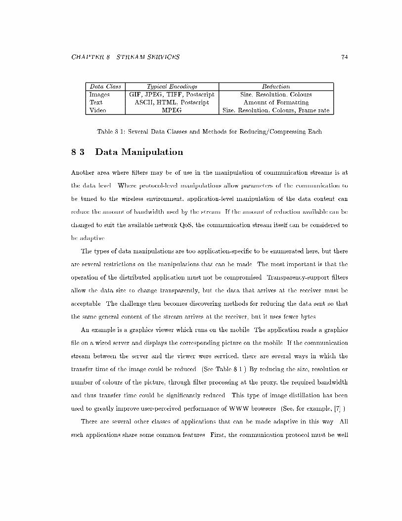
CHAPTER 8. STREAM SERVICES 74
Data Class Typical Encodings ReductionImages GIF, JPEG, TIFF, Postscript Size, Resolution, ColoursText ASCII, HTML, Postscript Amount of FormattingVideo MPEG Size, Resolution, Colours, Frame rate
Table 8.1: Several Data Classes and Methods for Reducing/Compressing Each
8.3 Data Manipulation
Another area where �lters may be of use in the manipulation of communication streams is at
the data level. Where protocol-level manipulations allow parameters of the communication to
be tuned to the wireless environment, application-level manipulation of the data content can
reduce the amount of bandwidth used by the stream. If the amount of reduction available can be
changed to suit the available network QoS, the communication stream itself can be considered to
be adaptive.
The types of data manipulations are too application-speci�c to be enumerated here, but there
are several restrictions on the manipulations that can be made. The most important is that the
operation of the distributed application must not be compromised. Transparency-support �lters
allow the data size to change transparently, but the data that arrives at the receiver must be
acceptable. The challenge then becomes discovering methods for reducing the data sent so that
the same general content of the stream arrives at the receiver, but it uses fewer bytes.
An example is a graphics viewer which runs on the mobile. The application reads a graphics
�le on a wired server and displays the corresponding picture on the mobile. If the communication
stream between the server and the viewer were serviced, there are several ways in which the
transfer time of the image could be reduced. (See Table 8.1.) By reducing the size, resolution or
number of colours of the picture, through �lter processing at the proxy, the required bandwidth
and thus transfer time could be signi�cantly reduced. This type of image distillation has been
used to greatly improve user-perceived performance of WWW browsers. (See, for example, [7].)
There are several other classes of applications that can be made adaptive in this way. All
such applications share some common features. First, the communication protocol must be well

CHAPTER 8. STREAM SERVICES 75
known. Unless the data formats and network protocol are known, the content of the messages
can not be extracted and modi�ed. Second, the data communicated must be modi�able. If the
data being sent is already fully compressed, no modi�cation is possible.
Examples of di�erent classes of application that can handle data reduction are presented in
the following sections.
8.3.1 Data Removal
There are applications that use time-sensitive information and are therefore capable of discarding
data that arrive late. This built-in tolerance can be exploited by delaying data units (DU)
inde�nitely at the intermediate router. The problem is to drop individual DUs so that the overall
performance is improved and the operation of the application is not compromised.
Consider the case of a real-time audio application. The player receives data from the network
and plays the data in order assuming that all the required packets have arrived. To allow some
time for slow packets to arrive, packets are bu�ered for a certain amount of time. If the data
has not arrived after that time, the player assumes the packet was lost and \plays" something
appropriate to �ll the blank space.
This application is now to be run on a wireless network after being designed for a wired network.
Lower bandwidth and variable delays can cause more packet losses than the application can
hide. In order to improve application performance, �lters could be used to reduce the bandwidth
required by the application by using a packet-dropping scheme. Under this scheme, the �lter
monitors the network checking for bandwidth saturation. In periods of low QoS, the �lter will
drop packets at regular intervals in an attempt to reduce the bandwidth requirement of the data
stream. Since the application is already designed to handle missing packets, it is possible for the
SP �lter to ensure a regular dropping pattern. This will make it easier for the application to hide
missing information instead of needing to �ll in large sections of lost data.
This kind of lowering of average performance in order to handle low QoS is a theme of all
application-level �lters. A prototype packet-dropping �lter was implemented which randomly
dropped packets. This �lter operates similarly to the one described in the example of Section 8.1.5.

CHAPTER 8. STREAM SERVICES 76
8.3.2 Hierarchical Discard
Another type of application that can tolerate the loss of data is those that send information in
a hierarchical encoding. In a hierarchical encoding, the most important information is sent as a
base layer. On top of this layer are consecutive levels of enhancement layers which add successive
levels of detail onto the base layer. This type of layering seems ideal for data-dropping schemes
since upper layers can be dropped and the most important information will get through.
One example where this would be of use is in the case of a mobile MPEG receiver. MPEG, the
streaming video encoding, uses a three-layer hierarchical encoding. Full JPEG images are sent in
a base layer, while two successive di�erential layers make up intermediate images for the video. If
it were necessary to reduce bandwidth utilization of an MPEG player during periods of low QoS,
one or both enhancement layers could be dropped from the communication stream using a proxy
�lter. This allows the bandwidth utilization of the stream to vary according to available QoS,
and the application to play at least the base frames of the video.
Once again, average performance is reduced in times of low QoS to ensure that at least the
base semantic information can be displayed by the receiver. There is currently no implementation
of this type of �lter, though one is currently being developed within the Shoshin group at the
University of Waterloo.
8.3.3 Data-Type Translation
Some viewer applications transfer data which do not have a set size, though it does have a set
format. If the object being transfered can be compressed or translated, a smaller object expressing
the same general information could be substituted in the communication stream. The level of
compression could also be tailored for the current conditions of the network, creating an adaptive
stream.
An example of information with these properties is HTML documents. Browsers use HTML,
which allows for the de�nition of image tags that do not specify image size. Images bound for the
viewer could then be converted to a smaller representation before being presented to the mobile
user. These images can be modi�ed in many di�erent ways (see Table 8.1) to give the same basic

CHAPTER 8. STREAM SERVICES 77
information contained in the original image, but using much less space.
In this case, no implementation work has been done using the proxy system implemented here,
though much work has been done elsewhere. In [7], a modi�ed viewer allowed users to specify
if they wanted to load the complete picture or perhaps zoom in on a particular portion or a
compressed image. Once again, the amount of compression can be tuned to the current network
conditions.

Chapter 9
Security Concerns
This chapter discusses various security concerns associated with the system proposed. The impact
of these concerns can be reduced by making several assumptions about the environment under
which the proxy system is used.
This system was designed for, and will eventually be merged with, routing code running on
routers into wireless networks. As it stands now, all service �lters have been created by the
service-proxy designers. For this reason, the SP services can be considered secure, much the same
as other router services. This greatly simpli�es security concerns since no external code is run
to modify communication streams, and thus the services themselves can be said to be secure. A
more general model where �lters can be loaded from arbitrary locations is left as future work.
Security of a proxy system is divided into two categories: �lter control and �lter execution.
Filter control involves the necessity of both the SP and the �lter user to securely control the opera-
tion of �lters. Filter-execution concerns involve the need to limit the e�ects of �lter malfunctions.
The assumption of locally controlled �lters greatly reduces the risks involved, as explained below.
The main areas of concern for maintaining secure �lter control are methods for loading and
controlling �lters from remote locations. The mobile application is concerned with making sure
that its streams are being serviced only by �lters that were loaded for its use. The SP wishes to
make sure that �lters are loaded only for the appropriate applications.
78

CHAPTER 9. SECURITY CONCERNS 79
These problems are greatly reduced because of the assumption about complete local control
at the router. Applications can rely on the router not to add services they did not request. Since
the available �lters and their services are already well known, applications can be sure of the
operations they will be making on their streams.
In order to make sure that applications do not interfere with the operation of other com-
munication streams, the SP can require that wild-card keys include the machine address of the
application making the request. It is assumed that a mobile user or application will not want
to sabotage their own streams by adding incompatible �lters to unrelated streams. This method
limits applications and users to applying �lters to their own streams.
Since all �lters have been designed and implemented for the SP running on the router, it can
be assumed that �lter execution is secure and will not interfere with the operation of other �lters
or with the other operations of the router. Misuse by applications on their own behalf is not,
however, impossible. Future work may include the addition of fault-recovery mechanisms in the
proxy run-time environment.
This proxy system is intended to be integrated into router implementations at or near wireless
networks and to provide additional services for mobile users. The question becomes one of trust
towards those that administer the routers. As long as the router is trusted, the proxy system does
not represent any more of a security risk than the trusting the router itself. If properly used, this
architecture provides a powerful aid in the design, implementation and use of mobile, adaptive
applications.

Chapter 10
Summary and Future Work
10.1 Summary
Proxies provide a method for dealing with the heterogeneity of wireless networks. Proxy systems
consist of a stream-interception and -processing intermediary, a network-monitoring component,
and a method for proxy-service control. The purpose of this system is to improve the perceived
performance of the network by manipulating the communication stream. The type of manipulation
depends on the underlying protocols, which can be \re-tuned" for wireless links, and the type of
application data, which may be dropped, delayed, or compressed.
These services require some kind of control. In previous work, it was up to the application
to request and control stream services. The types of manipulation can also adapt to the current
state of the stream. A network monitor provides information about the state of the network to
the application or service �lter. This allows stream services to operate more passively in times of
good QoS, and more aggressively in times of low QoS.
This thesis proposes a new paradigm of control for use with legacy applications. Since these
applications are beyond the control of the proxy-�lter programmer, a new level of transparency
is required to assign and control stream services. A solution is provided through a user interface
for third-party �lter control, and a protocol-manipulation �lter capable of hiding changes in
80

CHAPTER 10. SUMMARY AND FUTURE WORK 81
packet-data size. This new class of transparent service improves perceived performance without
compromising the operation of the application or communication protocols beneath.
The thesis began with an overview of existing protocols applicable to the wireless environment,
and the problems they encounter. Research related to proxy systems and wireless services was
presented and a proxy architecture was selected as the most viable solution to handle the variability
and low QoS of the wireless environment. The Comma proxy system was chosen as the platform
to use for this research and the operation of the related service proxy and network monitor
was described. An external service-control and monitoring shell named Kati was added to give
informed user-level control of proxy services. A new transparency-support �lter was created to
allow transparent data modi�cation in TCP. Finally, security issues related to this system were
discussed.
I feel that the main contribution of this work is the discovery of a new class of proxy ser-
vices which does not interfere with, or require the interaction of, the applications. This includes
contributions in the following areas.
� The design and implementation of a transparency-support �lter for TCP. This has included
some design and implementation work for both the Comma SP and EEM, especially as it
relates to their interfaces.
� Showing the versatility of third-party service control through the design and implementation
of Kati. Kati allows legacy applications to be serviced by proxy �lters and provides the user
with a greater level of control over server operation.
� Clarifying the problems related to split-stream �ltering, especially as it relates to the end-
to-end-semantics problem.
A transparency-support �lter for TCP was designed and implemented which makes changes
made by other �lters invisible to both sender and receiver. This was done by changing SEQ and
ACK numbers to give sender and receiver two di�erent views of the connection. The checksum
is also modi�ed to re ect the new packet contents. Finally, various caching and acknowledgment

CHAPTER 10. SUMMARY AND FUTURE WORK 82
strategies are used to give an enhanced level of service to data �lters relying on the TTSF's
services.
In order to support these �lters, a proxy architecture capable of controlling transparency-
support �lters is required. To this end the Comma SP and EEM were used. My contribution
to these components consisted of contributing to the design and implementation of parts of both
the SP and the EEM. The implementation work generally focused on creating interfaces for these
components. The Kati user interface was designed and implemented solely by myself to use these
interfaces.
This architecture allows legacy applications to be serviced by appropriate proxy services. Up
to this point, legacy applications have had to make do with the performance they are already
capable of on the wireless network. Since these application were designed for the higher and more
static QoS characteristics of the wired medium, their behaviour in wireless networks is potentially
very poor. With the discovery of transparency-support �lters, these applications can now be
serviced by proxy �lters. External user control through Kati allows application streams to be
serviced without interfering with application operation.
Third-party service control can also be used for reasons other than supporting legacy applica-
tions. This type of control can be used for greater user convenience by providing enhanced control
of their own computing environment. Applications can be assigned a communication priority using
protocol-level �lters. The user can also monitor communication patterns and network-environment
metrics to help in the creation of better distributed applications.
Finally, the problems related to split-stream �ltering were described, and the services of the
TTSF proposed as an alternative. Such per-packet manipulations allow end-to-end semantics to
be maintained while altering the data content of the communication streams.
This enhanced proxy system leads to wide range of future work.
CHAPTER 10. SUMMARY AND FUTURE WORK 83
10.2 Future Work
10.2.1 Layered Service Abstraction
One area of future interest is in the packet-processing abstraction. At the moment, packets
are simply passed from one �lter to another in a predetermined order. In order to create new
�lters, the operation of all other �lters must be understood so that there is no interference from
misordering.
An improvement would be to move �lters to a more opaque layered approach, such as that
proposed in the OSI protocol stack. In this view, �lters would interact at the protocol level
appropriate to the service the protocol provides. Data is passed up and down the layers as if the
SP were a virtual host. In this way, modi�cations at higher and lower layers can be ignored, and
only the �lters at the same level as the one being inserted need be accommodated in the creation
of new �lters. Since most complex �ltering occurs at the application level, new services would not
have to worry about lower level services.
This would be especially useful with transparent service support. Higher-level service pro-
grammers do not have to worry about protocol-level transparency in order to come up with
application-level services.
10.2.2 Operating-System Integration
Another extension of this work would be to integrate user-level control with the mobile-client's
operating system. By integrating the user interface with the client OS, it would be possible for
the user to indicate through indirect methods the types of services required for di�erent streams.
For instance, the application in the currently active window could be given priority, while hidden
or minimized windows could be given fewer resources or suspended. Also, application-control
services could be included on menus, giving a list of the appropriate network services currently
available. The current state of the network could be a standard performance window.

CHAPTER 10. SUMMARY AND FUTURE WORK 84
10.2.3 Mobility
An area not directly addressed in this thesis is the problem of service mobility. If a mobile were to
move to a new wireless subnet, it would be necessary not only to apply the appropriate services
to existing streams on the foreign SP, but also to transfer the associated service state as well.
The simplest solution would be to leave it to the SPs to co-ordinate state and service information,
either before, during or after a client hand-o�. This would result in a complex service model since
the �lters themselves would need to be able to supply state information at any point and also to
load such state at the new SP.
Another possibility which has been getting increasing attention is the use of mobile agents. In
this paradigm, the �lters themselves move from place to place carrying all service and state infor-
mation with them. Unfortunately, this technology is in its infancy and current support languages
such as Java aglets [15, 19] do not have the speed necessary for real-time packet processing. The
mobility of services also brings up a large number of security concerns that would need to be
addressed.
10.2.4 Double-Proxy Systems
One �nal area of interest is the creation of double-proxy systems. In such systems, a second proxy
is placed on the mobile that intercepts all arriving tra�c before it reaches the applications. Using
this method, communication could be arbitrarily manipulated between the two proxies as long as
the original format were restored by the second proxy before delivery to the application.

Bibliography
[1] E. Ayanoglu, S. Paul, T. F. LaPorta, K. K. Sabnani, and R. D. Gitlin. AIRMAIL: A link-layer
protocol for wireless networks. ACM/Baltzer Wireless Networks Journal, 1:47{60, February
1995.
[2] A. Bakre and B. R. Badrinath. I-TCP: Indirect TCP for mobile hosts. In Proceedings of the
15th International Conference on Distributed Computing Systems, pages 136{143, Vancouver,
BC, Canada, May 1995.
[3] H. Balakrishnan, V. N. Padmanabhan, S. Seshan, and R. H. Katz. A comparison of mech-
anisms for improving TCP performance over wireless links. In Proceedings of the ACM
SIGCOMM `96 Conference, pages 256{69, Stanford, California, USA, August 1996.
[4] H. Balakrishnan, S. Seshan, E. Amir, and R. H. Katz. Improving TCP/IP performance over
wireless networks. In Proceedings of the First Annual International Conference on Mobile
Computing and Networking, pages 2{11, Berkeley, California, USA, November 1995.
[5] J. D. Case, M. Fedor, M. L. Scho�stall, and C. Davin. Simple network management protocol
(SNMP), May 1990. RFC 1157.
[6] S. Deering. ICMP router discovery messages, September 1991. RFC 1256.
[7] A. Fox, S.D. Gribble, E.A. Brewer, and E. Amir. Adapting to network and client variablility
via on-demand dynamic distillation. In Proceedings of the Seventh International Conference
85

BIBLIOGRAPHY 86
on Architectural Support for Programming Languages and Operating Systems, pages 160{170,
Cambridge, MA, USA, October 1996.
[8] V. Jacobsen and R. Braden. TCP extentions for long-delay paths, October 1988. RFC 1072.
[9] V. Jacobson. Congestion control and avoidance. Computer Communication Review,
18(4):314{329, August 1988.
[10] V. Jacobson. Modi�ed TCP congestion avoidance algorithm, April 1990. end2end-interest
mailing list.
[11] A. D. Joseph, A. F. deLespinasse, J. A. Tauber, D. K. Gi�ord, and M. F. Kaashoek. Rover:
A toolkit for mobile information access. In Proceedings of the Fifteenth ACM Symposium
on Operating Systems Principles, pages 156{171, Copper Mountain Resort, Colorado, USA,
December 1995.
[12] A. D. Joseph, J. A. Tauber, and M. F. Kaashoek. Mobile computing with the Rover toolkit.
IEEE Transactions on Computers: Special Issue on Mobile Computing, 46(3), March 1997.
[13] D. Kidston, J. P. Black, T. Kunz, M. E. Nidd, M. Lioy, B. Elphick, and M. Ostrowski.
Comma, a communication manager for mobile applications. In Proceedings of Wireless '98,
pages 103{116, Calgary, Alberta, Canada, July 1998.
[14] M. Kojo, K. Raatikainen, and T. Alanko. Connecting mobile workstations to the Internet
over a digital cellular telephone network. In Tomasz Imielinski and Henry F. Korth, editors,
Mobile Computing, volume 353, pages 253{270. Kluwer, 1996.
[15] D. B. Lange and D. T. Chang. IBM Aglets Workbench, Programming Mobile Agents in Java,
A White Paper, September 1996.
[16] M. Liljeberg, H. Helin, M. Kojo, and K. Raatikainen. Enhanced service for World-Wide
Web in mobile WAN environment. Series of Publications C Num: C-1996-28, University of
Helsinki, Department of Computer Science, April 1996.

BIBLIOGRAPHY 87
[17] M. Lioy and J. P. Black. Providing network services at the base station in a wireless net-
working environment. In Proceedings of Wireless '97, pages 29{39, Calgary, Alberta, Canada,
July 1997.
[18] H. Y. Lo. M-mail: A case study of dynamic application partitioning in mobile computing.
Master's thesis, Dept. of Computer Science, University of Waterloo, May 1997.
[19] J. P. Munson and P. Dewan. Sync: A Java framework for mobile collaborative applications.
Computer, 30(6):59{66, June 1997.
[20] C. Perkins. IP mobility support, October 1996. RFC 2002.
[21] C. Perkins and D. B. Johnson. Route optimization in Mobile IP, November 1997. IETF
Internet-Draft.
[22] J. Postel. Internet control message protocol, September 1981. RFC 792.
[23] J. Postel. Transmission control protocol, September 1981. RFC 793.
[24] M. Satyanarayanan. Fundamental challenges in mobile computing. In Fifteenth ACM Sym-
posium on Principles of Distributed Computing, pages 1{7, Philadelphia, PA, USA, May
1996.
[25] W. Simpson. IP in IP tunneling, October 1995. RFC 1853.
[26] W. R. Stevens. TCP/IP Illustrated, Volume 1. Addison-Wesley Publishing Company, 1994.
[27] S. Wachsberg. E�cient information access for wireless computers. Master's thesis, Dept. of
Computer Science, University of Waterloo, September 1996.
[28] T. Watson. Application design for wireless computing. In Proceedings of the Workshop on
Mobile Computing Systems and Applications, pages 91{94, December 1994.
[29] T. Watson. E�ective wireless communication through applicatoin partitioning. In Proceedings
of the the Fifth Workshop on Hot Topics in Operating Systems, pages 24{27, May 1995.
BIBLIOGRAPHY 88
[30] B. Zenel and D. Duchamp. A general purpose proxy �ltering mechanism applied to the mobile
environment. In Proceedings of the Third Annual ACM/IEEE International Conference on
Mobile Computing and Networking, pages 248{259, Budapest, Hungary, September 1997.
[31] T. C. Zhao and M. Overmars. Forms library, a graphical user interface toolkit for X, March
1997. from: http://bragg.phys.uwm.edu/xforms.