transparent bridge developed by dec and adopted by 802.1 committee, transparent bridge consists of:...
Post on 21-Dec-2015
219 views
TRANSCRIPT

Transparent Bridge
Developed by DEC and adopted by 802.1 committee, transparent bridge consists of:
• Promiscuous listen and store and forward capabilities of “no-frills” bridge
• Station learning cache of the “learning bridge”
• Spanning tree algorithm of the “complete” bridge

No-Frills Bridge
• Basic form of bridge that attaches two or more LANS – Attachment is known as port
• Listens promiscuously for every packet transmitted from one LAN and stores each packet until it can be transmitted to another LAN

No-Frills Diagram
B
QP
port 2
port 1

No-Frills – Expectations
• Stations expect to transmit packets exactly as they would in a single-LAN environment
• Bridge must transmit packet exactly as it is received
• If bridge modifies packets in any way, i.e., by inserting is own address, protocols at the stations might not work properly
• They do not change delay characteristics (this might affect protocols having tight timers)

No-Frills – Advantages• For 802.3, allows length restriction to be exceeded• If connecter were a repeater instead of a bridge,
each repeated bit could collide as it was forwarded• Bridge receives entire packet, stores it and then
waits for LAN on other side to become idle• Two sides of bridge can therefore transmit
simultaneously without a collision
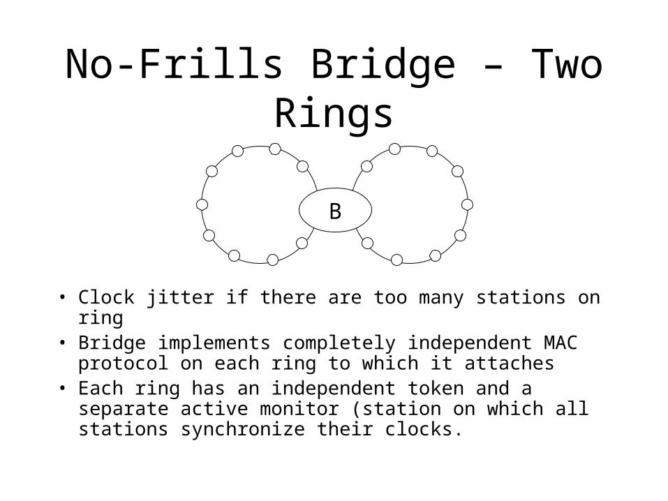
No-Frills Bridge – Two Rings
• Clock jitter if there are too many stations on ring• Bridge implements completely independent MAC protocol
on each ring to which it attaches• Each ring has an independent token and a separate active
monitor (station on which all stations synchronize their clocks.
B

No-Frills - Disadvantages
• Does not overcome LAN total bandwidth limit• If each LAN has 10 Mb/sec bandwidth, the total
bandwidth that can be safely used is 10 Mb/sec– Every packet transmitted on a LAN will end up on
every LAN
– Because of storage capacity of bridge, temporary peak could exceed 10 Mb/sec
– If temporary peak exceeded capacity of bridge, could be lucky enough to lose unneeded packets
Learning Bridge
The following three slides depict possible but impractical implementations

Learning Bridge – Manual Entry
Manually enter addresses of all stations into a database kept at the bridge
B
MA
port 2
port 1
typed by human
A Q M
Q

Learning Bridge - RangeNetwork manager enters a range for each LAN
B
39115
port 2
port 1
typed by human
100 > 100
23 52617

Learning Bridge – Station Addresses
• Network manager could assign station addresses so that a portion of the LAN address was attached
LAN station

Learning Bridge
The following implementation IS practical

Learning Bridge – Global IDStations could use globally assigned 48-bit ID stored in ROM by manufacturer and bridge could just figure out where stations are
B
12.27
3.5
port 2
port 1
typed by human
3.* 12.*
12.93.21

Learning Bridge – Why it Works
• Source station adds its global address to packet when it sends it
• Bridge does NOT add its address to packet
• Therefore, source address contains needed ID
Learning Bridge - Strategy• Listen promiscuously, receiving every packet transmitted
• Store address of packet’s source address field cache and port packet was received on
• For each packet received, look through station cache for address listed in packet destination field– If address is not found, forward packet onto all interfaces
– If address IS found, forward packet only onto interface (port) specified in the table
– If specified interface (port) is the one from which the packet was received, drop (filter) the packet
– Bridge ages each entry in station cache and deletes it after a period of time (aging vs British spelling ageing – surplus of vowels)

Bridge Learns As Address
Further traffic addressed to A will be routed to port 1
B
MA
port 2
port 1
DQ
D A data
destination source

Bridge Learns Ds Address
Further traffic addressed to D will be routed to port 2
B
MA
port 2
port 1
DQ
A D data
destination source

Bridge Learns Qs Address
Further traffic addressed to Q will be routed to port 1
B
MA
port 2
port 1
DQ
A Q data
destination source

Learning Bridge Activity
Messages• A to D – Bridge learns A is on port 1• D to A – Bridge learns D is on port 2. Bridge only forwards message
to port 1• Q to A – Bridge learns Q is on port 1. Bridge does not forward
message• Z to C – Bridge learns Z is on port 3. Bridge forwards message to
ports 1 and 2
B
MA
port 2
port 1
DQ Z C
port 3

3 LAN and 2 Bridge Example
B1
MA
port 2port 1
DQ
B2
T
port 2port 1
K
A Q K D M T D O M A T K
LAN 1 LAN 2 LAN 3

View from Bridge 1
B1
TA
port 2
port 1
KQ MD

View from Bridge 2
B2
M K
port 2
port 1
A TDQ

Networks with Loops
B1 B2 B3
LAN 1
LAN 2
A

Loop Problems• Assume A transmits a packet• Each of the bridges
– Receives the packet – Notes that A resides on LAN 1– Queues the packet for forwarding to LAN 2
• One of the bridges (say bridge 3) will succeed in transmitting the packet first
• Because bridge 3 is transparent to bridges 1 and 2, the packet will appear on LAN 2 exactly as if station A had transmitted it
• Thus, bridges 1 and 2– Receives the packet– Notes that A now resides on LAN 2– Queues the packet for forwarding to LAN 1
Loop Problems (Cont)
• Next, suppose bridge 1 succeeds in transmitting its first received packet to LAN 2
• Bridges 2 and 3 will receive the packet– Bridge 2 will note that A is still on LAN 2
– Bridge 3 will note that A has moved to LAN 2
– Both will then queue the “new” packet for forwarding to LAN 2
• Etc., etc.

Summary of Problems
• Packets loop
• Packets proliferate – Every successful packet transmission results in two new packets in the the system

Comparison with Routers• Packet looping occurs with routers• However, it is not nearly so bad as with bridges• Routers direct transmission to a specific router
– Therefore, a packet might be transmitted an infinite number of times
– However, packets will not spawn additional packets at each hop
– At any point, only a single copy of the packet will exist– Routers normally impose a max hop count
• Because bridges are transparent, the packet looks the same on the 25-thousandth transmission as it did on the first

Bridge Design Alternatives
• Decide that bridges are a bad idea• Keep topology loop free – If someone
inadvertently inserts a loop, smirk and tell offender to read the documentation
• Design bridges to detect loops and output error message – At least customer will be made aware of problem
• Design bridges so that they implement an algorithm (spanning tree) that prunes the topology into a loop-free subset

Spanning Tree
The purpose of a spanning tree algorithm is to have bridges
• Dynamically discover a subset of the topology that is loop free (a tree)
• Achieve just enough connectivity that (wherever possible), there is a path between every pair of LANS

Configuration Messages
• Bridges transmit spanning tree messages to each other that allows them to calculate a spanning tree
• 802.1 calls Spanning tree messages configuration bridge protocol data units (or configuration BPDUs)
• Perlman calls them configuration messages for short

Configuration Message Content
Configuration messages contain enough information so that bridges can• Elect a single bridge, among all of the bridges on all of the
LANs, as the root bridge• Calculate the distance of the shortest path from themselves
to the root bridge• Choose a port (known as the root port) that gives the best
path from themselves to the root bridge• Select ports to be included in the spanning tree – root ports
plus any ports on which “self” has been elected designated bridge

Spanning Tree Operation
• Data traffic is – Forwarded to and from ports in spanning tree– Discarded on receipt and is never forwarded
onto ports outside the spanning tree
• Configuration messages are transmitted by a bridge onto a port
• They are NOT forwarded from that LAN

Configuration Message Formatdestination
source DSAP SSAP configuration message
Initial Configuration Steps
Every bridge initially
• Assumes itself to be root
• Transmits configuration messages on each of its ports with– Its own ID as root and – Its own ID as transmitting bridge ID– 0 as cost

Subsequent Configuration Steps
Bridges continuously • Receive configuration messages on each of
their ports• Save the best configuration message from
each port• Best configuration message is determined
by comparing messages received and messages receiving bridge would transmit

The Best Configuration Message
Given two configuration messages C1 and C2• C1 is better than C2 if the root ID of C1 is
numerically lower than the root ID of C2• It the root IDs are equal, compare cost• If the root IDs and costs are equal, compare the
transmitting bridge IDs• Port ID serves as the final tiebreaker – Used when
two ports of a bridge connects to the same LAN

Comparisons of C1 and C2
C1 C2root ID
cost
transmitter root ID cost
transmitter
a. 29 15 35 31 12 32
b. 35 80 39 35 80 40
c. 35 15 80 35 18 38

Handling of Configuration Messages• Configuration messages can be ordered by
the multiprecision number consisting of– Root ID as most significant portion– Cost as next most significant portion– Transmitting bridge ID as least significant
portion
• If a bridge receives a better configuration message on a LAN than it would transmit, it no longer transmits configuration messages
• Algorithm terminates when only one bridge can transmit configuration messages on a LAN

Best Message Received
Root Cost Transmitter
Port 1 12 93 51
Port 2 12 85 47
Port 3 81 0 81
Port 4 15 31 27
• Assume bridge B has ID 18• The following are best configuration messages
received
• Best configuration message received is bridge ID 12 on port 2

Comparison with Bridge B Message
• Bridge B message is, 18.0.18 • Best message is, 12.85.47• Bs Configuration Message Becomes, 12.86.18 on
port 2 – It receives messages from the root bridge over port 2

Designated Bridge
• Bridge B is the designated bridge for a port if its configuration message is better that the best message received over that port
• In our example, bridge B is the designated bridge for ports 1, 3, and 4– Ports selected by B for inclusion in the spanning tree
are placed in a forwarding state, meaning B will forward data packets to and from those ports
– All other ports are placed in a blocking state, meaning B will NOT forward data packets to or from those ports
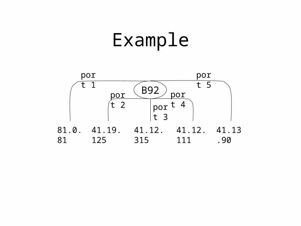
Example
port 3
B92port 2
port 4
port 5
port 1
41.12.315
41.19.125
41.13.90
41.12.111
81.0.81

Spanning Tree Ports
port 3
B92port 2
port 4
port 5
port 1
41.12.315
blocked
port
41.19.125
designated
port
41.13.90
blocked
port
41.12.111
root
port
81.0.81
designated
port

Failures
• The previous algorithm does not adapt to failures of bridges or links
• The following changes enables it toadapt– Configuration message for each port contains
an age field– Incremented after each time unit– When age reaches a maximum threshold,
discard configuration message

Failure Algorithm• When root bridge generates a configuration message, age
field is set to 0
• When bridges receive root’s configuration message, they transmit a configuration message on each of their ports for which they are designated with an age field of 0
• When bridges downstream from any designated bridge receive configuration message with age 0, they transmit their own configuration messages on all designated ports with age 0
• If the root fails or any component on the path between the root and the bridge fails, the bridge will stop receiving fresh (age = 0) configuration messages, causing root configuration message to age – time out

Consequences of Failure
• If the root fails or any component on the path between the root and the bridge fails, the bridge will stop receiving fresh (age = 0) configuration messages, causing root configuration message to age – time out
• At that point, discards configuration message and recalculates root, root path cost, and root port.

Configuration Message on Port 4 Times Out
port 3
B92port 2
port 4
port 5
port 1
41.12.315
41.19.125
41.13.90
41.12.111
81.0.81 41.13.92
Configuration message has timed out on port 4 but it has not timed out on port 3
– New root port is port 3
– New configuration message B92 transmits on ports 1 and 2 is
41.13.92

Configuration Messages on Ports 3 and 4 Time Out
port 3
B92port 2
port 4
port 5
port 1
41.19.125
41.13.90
41.12.111
81.0.81 41.14.92
41.12.315
Configuration messages have timed out on ports 3 and 4 but it has not timed out on port 5
– New root port is port 5
– New configuration message B92 transmits on ports 1 and 2 is
41.14.92

Configuration Messages on Ports 3, 4 and 5 Time Out
port 3
B92port 2
port 4
port 5
port 1
41.19.125
41.12.111
81.0.81
41.12.315
41.13.90
Configuration messages have timed out on ports 3, 4 and 5– New root port is port 5
– Bridge B92 assumes itself to be the root and transmits 92.0.92 on all
5 ports
– B92 continues transmitting 92.0.92 until it receives fresh a
configuration message from any of its ports regarding a better root

Spanning Tree CalculationThe following events cause spanning tree calculation:• Receipt of configuration message on port X
– Bridge compares received configuration message with stored configuration message
– If received is better or the same with smaller age, stored configuration message is overwritten and bridge recalculates root, cost, and root port
• Timer Tick– Bridge increments message field in stored
configuration message for each port– If message age reaches max age, bridge discards stored
configuration message and recalculates root, cost, and root port

Reason for Timer Tick
If the Designated Bridge only issued
configuration messages on receipt of
configuration messages from root,
• There is no reason to include age field
• On transmission, it would always be 0

Transmitting New Configuration Message with Age
• Assume that the following conditions exist on bridge B1:
– Configuration message from root has NOT timed out but it has age X
– Bridge B1 receives configuration message from newly activated bridge B2
• If B2 does not receive a configuration message from B1, B2 will assume it should become designated on that port, causing extra connectivity (looping)
• Instead, B1 sends a configuration message with age X
• The result is the same as if B2 had heard B1s configuration message when it was originally transmitted (X time units ago)

Topological Changes to System
• New bridge
• New link
• Bridge failure
• Link failure

Propagation of Topological Change
• News of change spreads throughout topology
• Until news of change has reached all bridges, the bridges will operate on inconsistent data

Short-Term Consequences of Change
• Temporary loss of connectivity – bridge NOT included in old topology isn’t aware yet that it is included in new topology
• Temporary loops – A bridge that was included in the old topology isn’t aware yet that it is NOT included in the new topology

Comparison with RoutersLoops with bridges are much bigger problems than
loops with routers because:• There is no loop count in the data link header• Packets can proliferate with bridges
– Bridge forwards the packet on several LANs
– Several bridges might pick up the packet when it is transmitted on a LAN
• Packets do not proliferate with routers:– Forward the packet in only one direction
– Specify the router which the packet is being forwarded

Loops• Almost anything is better in a bridged topology
than a loop• Temporary partitions are better in a bridged
topology than loops• Minimize probability of temporary loops by
– Waiting before allowing bridge port that was in blocking state to transition to a forwarding state
– Hopefully, all bridge ports that should be off in the new topology have already heard the news and turned themselves off before additional ports have started forwarding data
– Time to wait should be at least twice maximum transit time across the network

Example
• Suppose B1 issues a configuration message that is maximally delayed X time increments before reaching B2 on the other end of system
• If B1 fails, timeout occurs X time increments earlier on B1s end of the topology as on B2s end
• If B2 will be the new root, the configuration message for B2 will arrive X time increments earlier on B2s end of the topology as on B1’s end
Hello State
• When a bridge becomes aware that a new root needs to be calculated, it sends Hello messages for 2X time increments
• Then bridge forwards packets on designated ports
802.1 Standard
The 802.1 standard calls for two intermediate states• Listening – Minimizes learning of incorrect
station locations • Learning – To minimize unnecessary frame
forwarding, a bridge does not start forwarding until it has built up a “learned” cache

Station Cache Timeout Values
• Bridges learn and cache the location of stations• Since a station might move, bridge must forget,
unless it is frequently reassured information is correct
• Information may be delayed to a location that is incorrectly cached
• If an entry has been deleted, traffic for the deleted station will leak to other portions of the bridged network unnecessarily

Max and Min Timeout Values
• If timeout is too long, traffic will be lost for an unreasonably long time
• If timeout is too short, network performance will degrade because traffic is forwarded unnecessarily

Timeout of Minutes is Reasonable
Timer on the order of minutes is reasonable when a station is moved because
• It would probably take 15 minutes to unplug the station, move it, and plug the station back in
• Even if moved more quickly, it is reasonable that it would still take a few minutes for the system to start working again
• Although there are strategies where a moved station can come up more quickly (i.e., having moved station transmit multicast address to all stations in spanning tree), the worst case delays must be provided for because things frequently don’t work right away

Timeout of Minutes is Unreasonable
• Timer on the order of minutes is reasonable when a station is moved because
• The spanning tree takes considerably less than minutes to adapt to a new topology
• Station user does not understand why things mysteriously stop
• Station cannot correct its entry with a special mechanism such as transmitting multicast packet, because spanning tree reconfiguration occurs without station being aware of it

15 Seconds?
• A station that has not transmitted for 15 seconds probably isn’t receiving a lot of traffic
• The first few misrouted packets wouldn’t hurt too much
• Shortest timeout before serious degradation varies with application and topology

Configurable Timeout• Long in the usual case• Short following reconfiguration of the
spanning tree• Is reconfiguration of the spanning tree
detectable?– Yes, by some bridges– Others do not notice the reconfiguration even
though entries in their station cache significantly change

Notifying All Bridges
It is wise to enhance the spanning tree algorithm to notify all bridges of change
• Enhancement should not impact bandwidth by sending multicast message
• Instead when bridge A notices topology change, it notifies bridge B which is on As root port
• Bridge B informs its parent, and so on until the root is notified
Root Bridge Action
• When the root port is notified of a change it sets a topology change flag in its configuration message
• Other bridges set the topology change flag in their configuration messages on the ports they are the designated bridge as long as the flag is set in the configuration message from the root port

Summarized Activities
• Bridges noticing change send notification message on root port to parent bridge
• Upon receipt of notification, root port sets topology change flag in configuration message
• Bridges that receive configuration messages with topology change flag set, delay receiving messages using the short station cache timer until it starts receiving message without the topology change flag set

Network Parameters• All bridges must agree on the following
parameters:– Max Age: Time at which configuration message is
discarded– Hello Time: Time interval between the issue of
configuration messages– Forward Delay: Time spent in learning and listening
states. Half the time when it is decided a port should become part of the spanning tree and the time when data traffic is allowed to be forwarded to and from that port
• Root port includes network parameters in configuration message

Port ID
• Configuration message also contains port ID which has two purposes– Allows computation of spanning tree to be
deterministic. Given the same topology, the bridge will always select the same root port
– Allows loops formed through means other than bridges to be dealt with properly

Determinism – Diagram
B1
B2
port 2port 1
port 1
port 2port 3

Determinism – How it Happens
• B2 will receive two configuration messages saying B1 is root, with same cost and B1 as designated bridge
• Designated bridge includes port number in configuration message
• Here, B2 selects port 3 for root because B1’s port in configuration message is lower (port 1 vs port 2)

Looping – How it can OccurLoops can form because
• Two ports of a bridge hooked into same LAN
• Two ports of a bridge hooked into two LANs connected by a repeater
• Two ports of a bridge are hooked into different LAN segments connected by a simple bridge (doesn’t do spanning tree algorithm)

Two Ports Connected to Same LAN
B port 2port 1
port 3

Loop Averted
• In previous slide, B is root bridge (because it is the only bridge)
• B transmits configuration message B, 0, B, port # on each port
• It will receive configuration message transmitted from port 2 on port 1 and configuration message transmitted from port 1 on port 2
• From B, 0, B, 1 and B, 0, B, 2 it selects B, 0, B, 1• Better root is on port 2

Assigning Port Numbers and Priority – 802 Standard
• 802 standard allocates two bytes to ports
• The two bits are divided into two portions– Top byte is priority– Bottom byte specifies port
• Therefore, only 256 ports and 256 priority levels can be specified

Assigning Port Numbers and Priority Yourself
• Instead, assign your own priority– Ports 1-14 lowest – Ports 15-69 next – Ports 70-387 next– etc.
• Then you can assign 64K ports with arbitrarily many priority levels

Performance Issues
• Lack of receipt causes bridges to add connectivity
• Extra connectivity (loops) is potentially dangerous

Network Congestion• If the network becomes congested, the spanning
tree algorithm must run properly– Unnecessarily turning bridge ports on adds to
congestion– The algorithm may never recover
• Bridge must have sufficient CPU power– If bridge becomes bottleneck, it will start throwing
away packets before even looking at them– There is no way it can avoid throwing away
configuration messages, because it doesn’t know what the message is without looking at it
• Configuration messages should be sent regardless of network congestion – put them at the head of the queue

802.1 Requirements• 802.1 does not require adequate
performance
• It is possible for a bridge to be underpowered, and still conform to the standard
• Extended bridges with underpowered bridges do not perform well and can become totally unstable with congestion

Is Real Time Necessary?
• No, because it is possible for a bridge to have– Just enough processing power to receive every message
on the LAN– The ability to decide whether it is a data or
configuration message– And yet not have sufficient CPU power to run the
spanning tree algorithm until there is idle time on the LAN
• This is OK if the bridge is able to keep the “best” configuration message it has seen

One-Way Connectivity• It is possible for hardware to fail in such a way
that connectivity between two bridges on a LAN becomes one-way
• Bridge A can hear bridge B, but Bridge B cannot hear bridge A
• This situation can be cause by:– B’s receiver being dead or weak– A’s transmitter being dead or weak– Some component such as a repeater transmitting or
receiving badly

One-Way Connectivity – Loop Creation
B1
B2
root bridge
LAN 1LOOP
B

Causes of Loop• Assume B1 cannot hear B2
– If cause is that B1’s receiver is dead, B1 will not hear data packets on LAN 1 either
– However, B1 might assume it is designated bridge and forward packets onto LAN 1 causing a loop
– If cause is that B2’s receiver is dead, B2 will not forward packets from LAN 1
– However, B2 will be forwarding packets onto LAN 1 creating a loop

Problem Solution
• Bridge standard does not say what to do in this case
• One possibility is for any bridge that detects one-way connectivity to stop forwarding packets to and from that LAN until condition is corrected
• One way to detect is note receipt of persistent configuration messages even though yours are better – Indicates other bridge is not receiving your messages

Settable parameters1. Bridge Priority – 2 octet value that allows network manager to
influence root and designated bridges. It is appended as most significant portion of bridge ID
2. Port Priority – 1 octet value that allows network manager to influence port when bridge is connected in a loop
3. Hello Time – Time that elapses between generation of configuration messages by a bridge that assumes itself to be a root
4. Max Age – The message age value at which a stored configuration message is judged as too old and discarded
5. Forward delay – A parameter that temporarily prevents a bridge from starting to forward data packets to and from a link until news of a topology change has spread to all parts of the network. The value recommended in 802.1d is 15 seconds. Also serves as a value for the short cache timer used during topology changes
6. Long Cache Timer – The default recommended by 802.1 is 5 minutes
7. Path Cost – Cost to be added to root path cost field in a configuration message that is received on this port. Can be set individually on each port

Bridge Message Formats
Types of messages used in spanning tree
algorithm
• Configuration Messages
• Topology Change Notification Messages

Configuration Message Format# of
octets
2 protocol identifier
1 version
1 message type
1 TCA reserved TC
8 root ID
4 cost of path to root
8 bridge ID
2 port ID
2 message age
2 max age
2 hello time
2 forward delay

Configuration Message Fields
Protocol Identifier: Constant 0Version: Constant 0Message Type: Constant 0Flags:
TC – Least significant bit is topology change flag.TCA – Most significant bit is topology change notification acknowledgementRemaining bits in flags octet are not used
Root ID: The 8 octet root ID consists of a 2 octet priority followed by a 6 octet bridge ID that is the root
Cost of Path to Root: 4 octet unsigned binary number cost from bridge listed in root ID to bridge transmitting configuration message

Configuration Message Fields (Cont)
Bridge ID – 2 octet configured priority followed by 6 octet ID of bridge transmitting configuration message
Port ID – First octet is configurable priority. Second octet is port on which octet is transmitted
Message Age – Estimated time (in 1/256th sec) since root originally transmitted its configuration message
Max Age – Time (in 1/256th sec) at which configuration message should be deleted
Hello Time – Time (in 1/256th sec) between generation of configuration messages by root bridge
Forward Delay – Time (in 1/256th sec) that bridge should stay in each of its intermediate states before moving a port from blocking state to forwarding

Topology Change Notification Format
Protocol Identifier – Constant 0
Version – Constant 0
Message Type – Constant 128 (decimal)
# of octets
2 protocol identifier
1 version
1 message type

Multiply Connected Stations
Consequence of having incorrect entry in bridge’s station cache is that traffic may not get delivered to station

Multiply Connected Example
Z
B1 B2 B3 B4 B5 B6
S
packet 1 packet 2

Multiply Connected Example (Cont)
Z
B1 B2 B3 B4 B5 B6
S
packet 1packet 2
Assume Z transmits a packet on LAN – then:
• B4 thinks S is to the left, so it doesn’t transmit packet
• B3 thinks S is to the right, so it doesn’t transmit packet
• Packet is lost

Filtering• A bridge that discards a packet instead of forwarding it is
said to filter the packet
• Transparent bridge learns station addresses and performs filtering in that it doesn’t forward every packet
• After all bridges have learned locations of stations, traffic should travel to a station along shortest path in spanning tree and NOT “leak” to other parts of spanning tree
• Filtering can keep certain kinds of traffic confined to portions of the topology, i.e.:– synchronization protocol that would not work with delays imposed
by multiple servers and hosts could be confined to “compatible” LANs
– Terminal servers and hosts can be managed by different organizations in different portions of the spanning tree

Permanent Filtering
• 802.1 standard specifies that network management have ability to permanently set certain address in the filtering database of a bridge
• Instructions specify which ports the bridge should allow packets to traverse
• Particular address is entered into filtering database with an input port number and flags indicating output ports on which a packet from the input port should be forwarded
• Usually, addresses entered into filtering database are multicast addresses, but station addresses can also be entered
Filtering Example
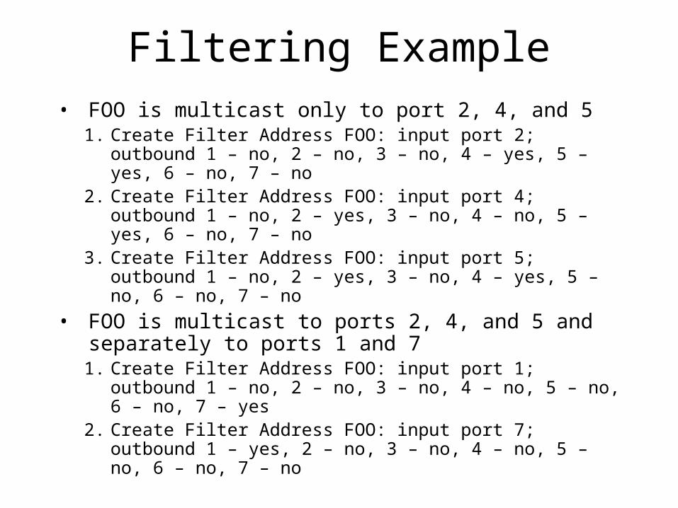
• FOO is multicast only to port 2, 4, and 51. Create Filter Address FOO: input port 2; outbound 1 –
no, 2 – no, 3 – no, 4 – yes, 5 – yes, 6 – no, 7 – no 2. Create Filter Address FOO: input port 4; outbound 1 –
no, 2 – yes, 3 – no, 4 – no, 5 – yes, 6 – no, 7 – no 3. Create Filter Address FOO: input port 5; outbound 1 –
no, 2 – yes, 3 – no, 4 – yes, 5 – no, 6 – no, 7 – no
• FOO is multicast to ports 2, 4, and 5 and separately to ports 1 and 7
1. Create Filter Address FOO: input port 1; outbound 1 – no, 2 – no, 3 – no, 4 – no, 5 – no, 6 – no, 7 – yes
2. Create Filter Address FOO: input port 7; outbound 1 – yes, 2 – no, 3 – no, 4 – no, 5 – no, 6 – no, 7 – no

Vendor-Specific Filtering
• Filtering based on SAP value rather than specific address
• Filtering based on source address

Filtering Problems
• Setting up filters can be tricky and counterintuitive
• Boundaries that you imagine with a particular physical topology might change when spanning tree defines logical topology
• You do not filter out bridge B, but since B is not is spanning tree, multicast messages do not go to it
Quantitative Problems
The “transparent” bridge might be better named the “translucent” bridge. Reasons for this are given on the following 6 slides.

1. Packet Loss Increases
• Even with sufficient packet storage capacity and an ability to read every packet, links can become congested causing packets to be dropped.
• Queues cannot be arbitrarily large because bridges do not have infinite buffering
• Even if queues could become arbitrarily large, delays would become excessive

2. Delay Increases
• At each hop, bridge must wait to acquire a channel
• A congested link along a path can cause packet to be queued behind others

3. Packet Lifetime Increases
• This has implications for higher-layer protocols
• Counters just large enough to avoid wrapping around during lifetimes on one LAN might wrap around during packet lifetimes across several bridge hops

4. Error Rate Increases• Two cases where data corruption can occur:
1. When data is being transmitted. Cyclic Redundancy Check (CRC) detects data transmission errors
2. In bridge memory or while a packet is being transmitted across a bus inside the system
• If bridges strip off CRC on receipt on regenerate on transmission, errors introduced inside the bridge will not be detected
• It is desirable to keep CRC received with packet and use same CRC on transmission
• However, bridges cannot always preserve original CRC due to differences in format
• CRC can be preserved only if bridge is forwarding packet between two LANs of the same type

5. Packet Misordering is Possible
Although unlikely, packets can become misordered during spanning tree reconfigurations
6. Duplicate Packets Increase
• Again, this problem is possible but not likely
• If a repeater were to come up joining two LANs that were previously separated within the spanning tree, there would be a temporary loop
• Packets on that loop would be duplicated a dramatic number of times

Qualitative Problems
In addition to quantitative performance-type problems, qualitative problems on the next 4 slides are also issues
1. Maximum Packet Size• Suppose LANs with different maximum packet sizes are
connected by bridges• Station emitting certain packet size will be certain to lose
packets when forwarding them to a stations on LANs with a smaller maximum packet size
• One Solution – Have several LANs use smallest maximum packet size– This is not satisfactory because two of these LANs could
communicate with larger packet size– Degrades throughput
• Another Solution – Have transport layer at the stations attempt to discover larger packet size– Not guaranteed over lifetime of transport connection because of
spanning tree reconfigurations– Facilitated by defining priority 0 on FDDI
• Low tech option is to have transport layer keep sending smaller packets until one gets through

2. LAN-Specific Info May Be Lost
• Some LANs have LAN-specific information fields in a packet, such as priority
• If a packet is transmitted form a LAN with a priority field onto a LAN without such a field and then back to a LAN with a priority field, there is no way to reconstruct the original priority

3. Unexpected Packet Conversion
Ethernet
6 6 2
D S P data
destination
source protocol type
802.3
6 6 2 1 1 1 3 2
D S length aa aa 3 0 P data
destination
source source DSAP SSAP CTL protocol
type
Problem• When translating from Ethernet to 802.3 format, RFC
1042 specifies using SNAP SAP format and 3 octet 0 for OUI followed by 2 octet Ethernet protocol
• After packet is translated into 802 format, it can be translated to other LAN types with minimal translation
• If the packet is eventually transmitted back to an Ethernet and first 3 bytes of protocol type are 0, there is no way for final bridge to know whether packet was originally transmitted in Ethernet or 802.3 format
• Must be able to accept a packet in Ethernet format and treat it exactly as it would be treated with 802.3 version

Another Problem
• AppleTalk uses the version number of its own protocol based on whether the packet was received in Ethernet or 802.3
• Vendors agreed to specifically check protocol type for value assigned to AppleTalk – say X
• If packet is in Ethernet format with protocol = X, instead of using 5-octet protocol type field in 802 consisting of 3 octets of 0 followed by X, they would use 00-00-f8

Bridge Assumptions
Bridges assume the following about station behavior
• A given data link source address can appear only in on location in the extended LAN. Some implementations of stations with multiple links use the same data link layer address on all ports. This confuses bridge caches
• A station receiving a lot of traffic will also be transmitting. If a destination never transmits, packets destined for that station cannot be localized, but rather must be transmitted to all the LANs throughout the spanning tree