transmission/transaxle cvt a b sectionpdf.textfiles.com/manuals/automobile/nissan/versa/... ·...
TRANSCRIPT

TRANSMISSION/TRANSAXLE
D
E
SECTION CVT A
B
VT
CCVTF
G
H
I
J
K
L
M
N
O
P
CONTENTS
RE0F08A
SERVICE INFORMATION ............................ 9
INDEX FOR DTC ................................................. 9Alphabetical Index .....................................................9DTC No. Index ..........................................................9
PRECAUTIONS ..................................................11Precaution for Supplemental Restraint System (SRS) "AIR BAG" and "SEAT BELT PRE-TEN-SIONER" .................................................................11Precaution Necessary for Steering Wheel Rota-tion After Battery Disconnect ...................................11Precaution for On Board Diagnosis (OBD) System of CVT and Engine ..................................................12Service After Replacing TCM and Transaxle As-sembly .....................................................................12Removal and Installation Procedure for CVT Unit Connector ................................................................13Precaution ...............................................................14Service Notice or Precaution ...................................15
PREPARATION ..................................................16Special Service Tool ...............................................16Commercial Service Tool ........................................16
CVT FLUID .........................................................17Checking CVT Fluid ................................................17Changing CVT Fluid ................................................18CVT Fluid Cooler Cleaning .....................................18
CVT SYSTEM .....................................................22Cross-Sectional View - RE0F08A ...........................22Control System ........................................................23Hydraulic Control System ........................................24TCM Function ..........................................................24CAN Communication ...............................................25Input/Output Signal of TCM .....................................26Line Pressure and Secondary Pressure Control .....26Shift Control ............................................................27Lock-up and Select Control .....................................28
Control Valve ...........................................................29
ON BOARD DIAGNOSTIC (OBD) SYSTEM ....30Introduction ..............................................................30OBD-II Function for CVT System ............................30One or Two Trip Detection Logic of OBD-II .............30OBD-II Diagnostic Trouble Code (DTC) ..................30Malfunction Indicator Lamp (MIL) ............................31
TROUBLE DIAGNOSIS ....................................33DTC Inspection Priority Chart ..................................33Fail-Safe ..................................................................33How to Perform Trouble Diagnosis for Quick and Accurate Repair .......................................................34CVT Electrical Parts Location ..................................39Circuit Diagram ........................................................40Inspections before Trouble Diagnosis .....................40Road Test ................................................................44Check before Engine Is Started ...............................45Check at Idle ............................................................45Cruise Test ..............................................................47Vehicle Speed When Shifting Gears .......................49TCM Terminal and Reference Value .......................49CONSULT-III Function (TRANSMISSION) ..............51Diagnosis Procedure without CONSULT-III ............59
DTC U1000 CAN COMMUNICATION LINE .....60Description ...............................................................60On Board Diagnosis Logic .......................................60Possible Cause ........................................................60DTC Confirmation Procedure ..................................60Wiring Diagram - CVT - CAN ...................................61Diagnosis Procedure ...............................................62
DTC U1010 TRANSMISSION CONTROL MODULE (CAN) ................................................63
Description ...............................................................63On Board Diagnosis Logic .......................................63Possible Cause ........................................................63DTC Confirmation Procedure ..................................63Diagnosis Procedure ...............................................63
CVT-1

DTC P0615 START SIGNAL CIRCUIT ............. 64Description .............................................................. 64CONSULT-III Reference Value in Data Monitor Mode ....................................................................... 64On Board Diagnosis Logic ...................................... 64Possible Cause ....................................................... 64DTC Confirmation Procedure ................................. 64Wiring Diagram - CVT - STSIG ............................... 65Diagnosis Procedure .............................................. 66
DTC P0703 STOP LAMP SWITCH CIRCUIT .... 67Description .............................................................. 67CONSULT-III Reference Value in Data Monitor Mode ....................................................................... 67On Board Diagnosis Logic ...................................... 67Possible Cause ....................................................... 67DTC Confirmation Procedure ................................. 67Diagnosis Procedure .............................................. 67
DTC P0705 PARK/NEUTRAL POSITION SWITCH ............................................................. 69
Description .............................................................. 69CONSULT-III Reference Value in Data Monitor Mode ....................................................................... 69On Board Diagnosis Logic ...................................... 69Possible Cause ....................................................... 69DTC Confirmation Procedure ................................. 69Wiring Diagram - CVT - PNP/SW ........................... 71Diagnosis Procedure .............................................. 72Component Inspection ............................................ 74
DTC P0710 CVT FLUID TEMPERATURE SENSOR CIRCUIT ............................................. 75
Description .............................................................. 75CONSULT-III Reference Value in Data Monitor Mode ....................................................................... 75On Board Diagnosis Logic ...................................... 75Possible Cause ....................................................... 75DTC Confirmation Procedure ................................. 75Wiring Diagram - CVT - FTS ................................... 76Diagnosis Procedure .............................................. 77Component Inspection ............................................ 78
DTC P0715 INPUT SPEED SENSOR CIR-CUIT (PRI SPEED SENSOR) ............................ 80
Description .............................................................. 80CONSULT-III Reference Value in Data Monitor Mode ....................................................................... 80On Board Diagnosis Logic ...................................... 80Possible Cause ....................................................... 80DTC Confirmation Procedure ................................. 80Wiring Diagram - CVT - PRSCVT ........................... 81Diagnosis Procedure .............................................. 82
DTC P0720 VEHICLE SPEED SENSOR CVT (SECONDARY SPEED SENSOR) ..................... 84
Description .............................................................. 84CONSULT-III Reference Value in Data Monitor Mode ....................................................................... 84On Board Diagnosis Logic ...................................... 84
Possible Cause ....................................................... 84DTC Confirmation Procedure .................................. 84Wiring Diagram - CVT - SESCVT ........................... 85Diagnosis Procedure ............................................... 86
DTC P0725 ENGINE SPEED SIGNAL .............. 89Description .............................................................. 89CONSULT-III Reference Value in Data Monitor Mode ....................................................................... 89On Board Diagnosis Logic ...................................... 89Possible Cause ....................................................... 89DTC Confirmation Procedure .................................. 89Diagnosis Procedure ............................................... 89
DTC P0730 BELT DAMAGE ............................. 91Description .............................................................. 91CONSULT-III Reference Value in Data Monitor Mode ....................................................................... 91On Board Diagnosis Logic ...................................... 91Possible Cause ....................................................... 91DTC Confirmation Procedure .................................. 91Diagnosis Procedure ............................................... 91
DTC P0740 TORQUE CONVERTER CLUTCH SOLENOID VALVE ........................................... 92
Description .............................................................. 92CONSULT-III Reference Value in Data Monitor Mode ....................................................................... 92On Board Diagnosis Logic ...................................... 92Possible Cause ....................................................... 92DTC Confirmation Procedure .................................. 92Wiring Diagram - CVT - TCV .................................. 93Diagnosis Procedure ............................................... 94Component Inspection ............................................ 95
DTC P0744 A/T TCC S/V FUNCTION (LOCK-UP) ..................................................................... 97
Description .............................................................. 97CONSULT-III Reference Value in Data Monitor Mode ....................................................................... 97On Board Diagnosis Logic ...................................... 97Possible Cause ....................................................... 97DTC Confirmation Procedure .................................. 97Diagnosis Procedure ............................................... 97
DTC P0745 LINE PRESSURE SOLENOID VALVE ............................................................... 99
Description .............................................................. 99CONSULT-III Reference Value in Data Monitor Mode ....................................................................... 99On Board Diagnosis Logic ...................................... 99Possible Cause ....................................................... 99DTC Confirmation Procedure .................................. 99Wiring Diagram - CVT - LPSV .............................. 100Diagnosis Procedure ............................................. 101Component Inspection .......................................... 102
DTC P0746 PRESSURE CONTROL SOLE-NOID A PERFORMANCE (LINE PRESSURE SOLENOID VALVE) .........................................104
CVT-2

D
E
F
G
H
I
J
K
L
M
A
B
VT
N
O
P
N
C
Description ............................................................ 104CONSULT-III Reference Value in Data Monitor Mode ..................................................................... 104On Board Diagnosis Logic .................................... 104Possible Cause ..................................................... 104DTC Confirmation Procedure ................................ 104Diagnosis Procedure ............................................. 104
DTC P0776 PRESSURE CONTROL SOLE-NOID B PERFORMANCE (SEC PRESSURE SOLENOID VALVE) ......................................... 106
Description ............................................................ 106CONSULT-III Reference Value in Data Monitor Mode ..................................................................... 106On Board Diagnosis Logic .................................... 106Possible Cause ..................................................... 106DTC Confirmation Procedure ................................ 106Diagnosis Procedure ............................................. 106
DTC P0778 PRESSURE CONTROL SOLE-NOID B ELECTRICAL (SEC PRESSURE SO-LENOID VALVE) .............................................. 108
Description ............................................................ 108CONSULT-III Reference Value in Data Monitor Mode ..................................................................... 108On Board Diagnosis Logic .................................... 108Possible Cause ..................................................... 108DTC Confirmation Procedure ................................ 108Wiring Diagram - CVT - SECPSV ......................... 109Diagnosis Procedure ............................................. 110Component Inspection .......................................... 111
DTC P0840 TRANSMISSION FLUID PRES-SURE SENSOR A CIRCUIT (SEC PRES-SURE SENSOR) ............................................... 113
Description ............................................................ 113CONSULT-III Reference Value in Data Monitor Mode ..................................................................... 113On Board Diagnosis Logic .................................... 113Possible Cause ..................................................... 113DTC Confirmation Procedure ................................ 113Wiring Diagram - CVT - SECPS ............................ 114Diagnosis Procedure ............................................. 115
DTC P0841 PRESSURE SENSOR FUNC-TION ................................................................. 117
Description ............................................................ 117CONSULT-III Reference Value in Data Monitor Mode ..................................................................... 117On Board Diagnosis Logic .................................... 117Possible Cause ..................................................... 117DTC Confirmation Procedure ................................ 117Diagnosis Procedure ............................................. 117
DTC P0845 TRANSMISSION FLUID PRES-SURE SENSOR B CIRCUIT (PRI PRESSURE SENSOR) .......................................................... 119
Description ............................................................ 119
CONSULT-III Reference Value in Data Monitor Mode ......................................................................119On Board Diagnosis Logic .....................................119Possible Cause ......................................................119DTC Confirmation Procedure ................................119Wiring Diagram - CVT - PRIPS .............................120Diagnosis Procedure .............................................121
DTC P0868 SECONDARY PRESSURE DOWN ............................................................. 123
Description .............................................................123CONSULT-III Reference Value in Data Monitor Mode ......................................................................123On Board Diagnosis Logic .....................................123Possible Cause ......................................................123DTC Confirmation Procedure ................................123Diagnosis Procedure .............................................123
DTC P1701 TRANSMISSION CONTROL MODULE (POWER SUPPLY) ......................... 125
Description .............................................................125On Board Diagnosis Logic .....................................125Possible Cause ......................................................125DTC Confirmation Procedure ................................125Wiring Diagram - CVT - POWER ...........................126Diagnosis Procedure .............................................127
DTC P1705 THROTTLE POSITION SENSOR . 129Description .............................................................129CONSULT-III Reference Value in Data Monitor Mode ......................................................................129On Board Diagnosis Logic .....................................129Possible Cause ......................................................129DTC Confirmation Procedure ................................129Diagnosis Procedure .............................................129
DTC P1722 ESTM VEHICLE SPEED SIGNAL . 131Description .............................................................131CONSULT-III Reference Value in Data Monitor Mode ......................................................................131On Board Diagnosis Logic .....................................131Possible Cause ......................................................131DTC Confirmation Procedure ................................131Diagnosis Procedure .............................................131
DTC P1723 CVT SPEED SENSOR FUNC-TION ................................................................ 133
Description .............................................................133On Board Diagnosis Logic .....................................133Possible Cause ......................................................133DTC Confirmation Procedure ................................133Diagnosis Procedure .............................................133
DTC P1726 ELECTRIC THROTTLE CON-TROL SYSTEM ............................................... 135
Description .............................................................135On Board Diagnosis Logic .....................................135Possible Cause ......................................................135DTC Confirmation Procedure ................................135Diagnosis Procedure .............................................135
CVT-3

DTC P1740 LOCK-UP SELECT SOLENOID VALVE CIRCUIT .............................................. 136
Description .............................................................136CONSULT-III Reference Value in Data Monitor Mode ......................................................................136On Board Diagnosis Logic .....................................136Possible Cause ......................................................136DTC Confirmation Procedure ................................136Wiring Diagram - CVT - L/USSV ............................137Diagnosis Procedure .............................................138Component Inspection ...........................................139
DTC P1745 LINE PRESSURE CONTROL ...... 140Description .............................................................140On Board Diagnosis Logic .....................................140Possible Cause ......................................................140DTC Confirmation Procedure ................................140Diagnosis Procedure .............................................140
DTC P1777 STEP MOTOR - CIRCUIT ............ 141Description .............................................................141CONSULT-III Reference Value in Data Monitor Mode ......................................................................141On Board Diagnosis Logic .....................................141Possible Cause ......................................................141DTC Confirmation Procedure ................................141Wiring Diagram - CVT - STM .................................142Diagnosis Procedure .............................................143Component Inspection ...........................................144
DTC P1778 STEP MOTOR - FUNCTION ........ 145Description .............................................................145CONSULT-III Reference Value in Data Monitor Mode ......................................................................145On Board Diagnosis Logic .....................................145Possible Cause ......................................................145DTC Confirmation Procedure ................................145Diagnosis Procedure .............................................146
OVERDRIVE CONTROL SWITCH .................. 147Description .............................................................147CONSULT-III Reference Value in Data Monitor Mode ......................................................................147Wiring Diagram - CVT - ODSW .............................148Diagnosis Procedure .............................................148Component Inspection ...........................................150
SHIFT POSITION INDICATOR CIRCUIT ........ 152Description .............................................................152CONSULT-III Reference Value in Data Monitor Mode ......................................................................152Diagnosis Procedure .............................................152
TROUBLE DIAGNOSIS FOR SYMPTOMS ..... 153Wiring Diagram - CVT - NONDTC .........................153O/D OFF Indicator Lamp Does Not Come On .......155Engine Cannot Be Started in "P" and "N" Position ..157In "P" Position, Vehicle Moves Forward or Back-ward When Pushed ...............................................157In "N" Position, Vehicle Moves ..............................158
Large Shock "N" → "R" Position ........................... 158Vehicle Does Not Creep Backward in "R" Position . 159Vehicle Does Not Creep Forward in "D" or "L" Po-sition ...................................................................... 160Vehicle Speed Does Not Change in "L" Position .. 161Vehicle Speed Does Not Change in overdrive-off mode ..................................................................... 162Vehicle Speed Does Not Change in "D" Position . 163Vehicle Does Not Decelerate by Engine Brake .... 163
CVT SHIFT LOCK SYSTEM .............................165Description ............................................................ 165Shift Lock System Electrical Parts Location .......... 165Wiring Diagram - CVT - SHIFT ............................. 166Diagnosis Procedure ............................................. 166
TRANSMISSION CONTROL MODULE ...........170Removal and Installation ....................................... 170
SHIFT CONTROL SYSTEM .............................171Removal and Installation ....................................... 171Control Device Disassembly and Assembly ......... 174Selector Lever Knob Removal and Installation ..... 174Adjustment of CVT Position .................................. 175Checking of CVT Position ..................................... 175
KEY INTERLOCK CABLE ...............................177Removal and Installation ....................................... 177
AIR BREATHER HOSE ....................................180Removal and Installation ....................................... 180
DIFFERENTIAL SIDE OIL SEAL .....................181Removal and Installation ....................................... 181
TRANSAXLE ASSEMBLY ...............................182Removal and Installation ....................................... 182
SERVICE DATA AND SPECIFICATIONS (SDS) ................................................................185
General Specification ............................................ 185Vehicle Speed When Shifting Gears ..................... 185Stall Speed ............................................................ 185Line Pressure ........................................................ 185Solenoid Valves .................................................... 186CVT Fluid Temperature Sensor ............................ 186Primary Speed Sensor .......................................... 186Secondary Speed Sensor ..................................... 186Removal and Installation ....................................... 186
RE0F08B
SERVICE INFORMATION .........................187
INDEX FOR DTC ..............................................187Alphabetical Index ................................................. 187DTC No. Index ...................................................... 187
PRECAUTIONS ................................................189Precaution for Supplemental Restraint System (SRS) "AIR BAG" and "SEAT BELT PRE-TEN-SIONER" ............................................................... 189
CVT-4

D
E
F
G
H
I
J
K
L
M
A
B
VT
N
O
P
N
C
Precaution Necessary for Steering Wheel Rota-tion After Battery Disconnect ................................. 189Precaution for On Board Diagnosis (OBD) System of CVT and Engine ................................................ 190Service After Replacing TCM and Transaxle As-sembly ................................................................... 190Removal and Installation Procedure for CVT Unit Connector .............................................................. 191Precaution ............................................................. 192Service Notice or Precaution ................................. 193
PREPARATION ................................................ 195Special Service Tool ............................................. 195Commercial Service Tool ...................................... 195
CVT FLUID ....................................................... 196Checking CVT Fluid .............................................. 196Changing CVT Fluid .............................................. 197CVT Fluid Cooler Cleaning ................................... 197
CVT SYSTEM ................................................... 201Cross-Sectional View - RE0F08B ......................... 201Control System ...................................................... 202Hydraulic Control System ...................................... 203TCM Function ........................................................ 203CAN Communication ............................................. 204Input/Output Signal of TCM ................................... 204Line Pressure and Secondary Pressure Control ... 205Shift Control .......................................................... 205Lock-up and Select Control ................................... 207Control Valve ......................................................... 207
ON BOARD DIAGNOSTIC (OBD) SYSTEM .... 209Introduction ........................................................... 209OBD-II Function for CVT System .......................... 209One or Two Trip Detection Logic of OBD-II .......... 209OBD-II Diagnostic Trouble Code (DTC) ................ 209Malfunction Indicator Lamp (MIL) .......................... 210
TROUBLE DIAGNOSIS ................................... 212DTC Inspection Priority Chart ............................... 212Fail-Safe ................................................................ 212How to Perform Trouble Diagnosis for Quick and Accurate Repair .................................................... 213CVT Electrical Parts Location ............................... 218Circuit Diagram ..................................................... 219Inspections before Trouble Diagnosis ................... 219Road Test .............................................................. 223Check before Engine Is Started ............................ 224Check at Idle ......................................................... 224Cruise Test ............................................................ 226Vehicle Speed When Shifting Gears ..................... 228TCM Terminal and Reference Value ..................... 228CONSULT-III Function (TRANSMISSION) ........... 230Diagnosis Procedure without CONSULT-III .......... 237
DTC U1000 CAN COMMUNICATION LINE ..... 238Description ............................................................ 238On Board Diagnosis Logic .................................... 238Possible Cause ..................................................... 238
DTC Confirmation Procedure ................................238Wiring Diagram - CVT - CAN .................................239Diagnosis Procedure .............................................240
DTC U1010 TRANSMISSION CONTROL MODULE (CAN) .............................................. 241
Description .............................................................241On Board Diagnosis Logic .....................................241Possible Cause ......................................................241DTC Confirmation Procedure ................................241Diagnosis Procedure .............................................241
DTC P0703 STOP LAMP SWITCH CIRCUIT . 242Description .............................................................242CONSULT-III Reference Value in Data Monitor Mode ......................................................................242On Board Diagnosis Logic .....................................242Possible Cause ......................................................242DTC Confirmation Procedure ................................242Diagnosis Procedure .............................................242
DTC P0705 PARK/NEUTRAL POSITION SWITCH ........................................................... 244
Description .............................................................244CONSULT-III Reference Value in Data Monitor Mode ......................................................................244On Board Diagnosis Logic .....................................244Possible Cause ......................................................244DTC Confirmation Procedure ................................244Wiring Diagram - CVT - PNP/SW ..........................245Diagnosis Procedure .............................................246Component Inspection ...........................................247
DTC P0710 CVT FLUID TEMPERATURE SENSOR CIRCUIT .......................................... 249
Description .............................................................249CONSULT-III Reference Value in Data Monitor Mode ......................................................................249On Board Diagnosis Logic .....................................249Possible Cause ......................................................249DTC Confirmation Procedure ................................249Wiring Diagram - CVT - FTS .................................250Diagnosis Procedure .............................................251Component Inspection ...........................................252
DTC P0715 INPUT SPEED SENSOR CIR-CUIT (PRI SPEED SENSOR) .......................... 254
Description .............................................................254CONSULT-III Reference Value in Data Monitor Mode ......................................................................254On Board Diagnosis Logic .....................................254Possible Cause ......................................................254DTC Confirmation Procedure ................................254Wiring Diagram - CVT - PRSCVT ..........................255Diagnosis Procedure .............................................256
DTC P0720 VEHICLE SPEED SENSOR CVT (SECONDARY SPEED SENSOR) .................. 258
Description .............................................................258
CVT-5

CONSULT-III Reference Value in Data Monitor Mode ......................................................................258On Board Diagnosis Logic .....................................258Possible Cause ......................................................258DTC Confirmation Procedure ................................258Wiring Diagram - CVT - SESCVT ..........................259Diagnosis Procedure .............................................260
DTC P0725 ENGINE SPEED SIGNAL ............ 263Description .............................................................263CONSULT-III Reference Value in Data Monitor Mode ......................................................................263On Board Diagnosis Logic .....................................263Possible Cause ......................................................263DTC Confirmation Procedure ................................263Diagnosis Procedure .............................................263
DTC P0730 BELT DAMAGE ........................... 265Description .............................................................265CONSULT-III Reference Value in Data Monitor Mode ......................................................................265On Board Diagnosis Logic .....................................265Possible Cause ......................................................265DTC Confirmation Procedure ................................265Diagnosis Procedure .............................................265
DTC P0740 TORQUE CONVERTER CLUTCH SOLENOID VALVE .......................................... 266
Description .............................................................266CONSULT-III Reference Value in Data Monitor Mode ......................................................................266On Board Diagnosis Logic .....................................266Possible Cause ......................................................266DTC Confirmation Procedure ................................266Wiring Diagram - CVT - TCV .................................267Diagnosis Procedure .............................................268Component Inspection ...........................................269
DTC P0744 A/T TCC S/V FUNCTION (LOCK-UP) ................................................................... 271
Description .............................................................271CONSULT-III Reference Value in Data Monitor Mode ......................................................................271On Board Diagnosis Logic .....................................271Possible Cause ......................................................271DTC Confirmation Procedure ................................271Diagnosis Procedure .............................................271
DTC P0745 LINE PRESSURE SOLENOID VALVE ............................................................. 273
Description .............................................................273CONSULT-III Reference Value in Data Monitor Mode ......................................................................273On Board Diagnosis Logic .....................................273Possible Cause ......................................................273DTC Confirmation Procedure ................................273Wiring Diagram - CVT - LPSV ...............................274Diagnosis Procedure .............................................275Component Inspection ...........................................276
DTC P0746 PRESSURE CONTROL SOLE-NOID A PERFORMANCE (LINE PRESSURE SOLENOID VALVE) .........................................278
Description ............................................................ 278CONSULT-III Reference Value in Data Monitor Mode ..................................................................... 278On Board Diagnosis Logic .................................... 278Possible Cause ..................................................... 278DTC Confirmation Procedure ................................ 278Diagnosis Procedure ............................................. 278
DTC P0776 PRESSURE CONTROL SOLE-NOID B PERFORMANCE (SEC PRESSURE SOLENOID VALVE) .........................................280
Description ............................................................ 280CONSULT-III Reference Value in Data Monitor Mode ..................................................................... 280On Board Diagnosis Logic .................................... 280Possible Cause ..................................................... 280DTC Confirmation Procedure ................................ 280Diagnosis Procedure ............................................. 280
DTC P0778 PRESSURE CONTROL SOLE-NOID B ELECTRICAL (SEC PRESSURE SO-LENOID VALVE) ..............................................282
Description ............................................................ 282CONSULT-III Reference Value in Data Monitor Mode ..................................................................... 282On Board Diagnosis Logic .................................... 282Possible Cause ..................................................... 282DTC Confirmation Procedure ................................ 282Wiring Diagram - CVT - SECPSV ......................... 283Diagnosis Procedure ............................................. 284Component Inspection .......................................... 285
DTC P0840 TRANSMISSION FLUID PRES-SURE SENSOR A CIRCUIT (SEC PRES-SURE SENSOR) ...............................................287
Description ............................................................ 287CONSULT-III Reference Value in Data Monitor Mode ..................................................................... 287On Board Diagnosis Logic .................................... 287Possible Cause ..................................................... 287DTC Confirmation Procedure ................................ 287Wiring Diagram - CVT - SECPS ........................... 288Diagnosis Procedure ............................................. 289
DTC P0841 PRESSURE SENSOR FUNC-TION ..................................................................291
Description ............................................................ 291CONSULT-III Reference Value in Data Monitor Mode ..................................................................... 291On Board Diagnosis Logic .................................... 291Possible Cause ..................................................... 291DTC Confirmation Procedure ................................ 291Diagnosis Procedure ............................................. 291
DTC P0868 SECONDARY PRESSURE DOWN ...............................................................293
CVT-6

D
E
F
G
H
I
J
K
L
M
A
B
VT
N
O
P
N
C
Description ............................................................ 293CONSULT-III Reference Value in Data Monitor Mode ..................................................................... 293On Board Diagnosis Logic .................................... 293Possible Cause ..................................................... 293DTC Confirmation Procedure ................................ 293Diagnosis Procedure ............................................. 293
DTC P1701 TRANSMISSION CONTROL MODULE (POWER SUPPLY) .......................... 295
Description ............................................................ 295On Board Diagnosis Logic .................................... 295Possible Cause ..................................................... 295DTC Confirmation Procedure ................................ 295Wiring Diagram - CVT - POWER .......................... 296Diagnosis Procedure ............................................. 297
DTC P1705 THROTTLE POSITION SENSOR ..299Description ............................................................ 299CONSULT-III Reference Value in Data Monitor Mode ..................................................................... 299On Board Diagnosis Logic .................................... 299Possible Cause ..................................................... 299DTC Confirmation Procedure ................................ 299Diagnosis Procedure ............................................. 299
DTC P1722 ESTM VEHICLE SPEED SIGNAL ..301Description ............................................................ 301CONSULT-III Reference Value in Data Monitor Mode ..................................................................... 301On Board Diagnosis Logic .................................... 301Possible Cause ..................................................... 301DTC Confirmation Procedure ................................ 301Diagnosis Procedure ............................................. 301
DTC P1723 CVT SPEED SENSOR FUNC-TION ................................................................. 303
Description ............................................................ 303On Board Diagnosis Logic .................................... 303Possible Cause ..................................................... 303DTC Confirmation Procedure ................................ 303Diagnosis Procedure ............................................. 303
DTC P1726 ELECTRIC THROTTLE CON-TROL SYSTEM ................................................ 305
Description ............................................................ 305On Board Diagnosis Logic .................................... 305Possible Cause ..................................................... 305DTC Confirmation Procedure ................................ 305Diagnosis Procedure ............................................. 305
DTC P1740 LOCK-UP SELECT SOLENOID VALVE CIRCUIT .............................................. 306
Description ............................................................ 306CONSULT-III Reference Value in Data Monitor Mode ..................................................................... 306On Board Diagnosis Logic .................................... 306Possible Cause ..................................................... 306DTC Confirmation Procedure ................................ 306Wiring Diagram - CVT - L/USSV ........................... 307
Diagnosis Procedure .............................................308Component Inspection ...........................................309
DTC P1745 LINE PRESSURE CONTROL ..... 310Description .............................................................310On Board Diagnosis Logic .....................................310Possible Cause ......................................................310DTC Confirmation Procedure ................................310Diagnosis Procedure .............................................310
DTC P1777 STEP MOTOR - CIRCUIT ........... 311Description .............................................................311CONSULT-III Reference Value in Data Monitor Mode ......................................................................311On Board Diagnosis Logic .....................................311Possible Cause ......................................................311DTC Confirmation Procedure ................................311Wiring Diagram - CVT - STM .................................312Diagnosis Procedure .............................................313Component Inspection ...........................................314
DTC P1778 STEP MOTOR - FUNCTION ....... 315Description .............................................................315CONSULT-III Reference Value in Data Monitor Mode ......................................................................315On Board Diagnosis Logic .....................................315Possible Cause ......................................................315DTC Confirmation Procedure ................................315Diagnosis Procedure .............................................316
OVERDRIVE CONTROL SWITCH .................. 317Description .............................................................317CONSULT-III Reference Value in Data Monitor Mode ......................................................................317Wiring Diagram - CVT - ODSW .............................318Diagnosis Procedure .............................................318Component Inspection ...........................................320
SHIFT POSITION INDICATOR CIRCUIT ........ 322Description .............................................................322CONSULT-III Reference Value in Data Monitor Mode ......................................................................322Diagnosis Procedure .............................................322
TROUBLE DIAGNOSIS FOR SYMPTOMS .... 323Wiring Diagram - CVT - NONDTC .........................323O/D OFF Indicator Lamp Does Not Come On .......325Engine Cannot Be Started in "P" and "N" Position ..327In "P" Position, Vehicle Moves Forward or Back-ward When Pushed ...............................................327In "N" Position, Vehicle Moves ..............................328Large Shock "N" → "R" Position ............................328Vehicle Does Not Creep Backward in "R" Position ..329Vehicle Does Not Creep Forward in "D" or "L" Po-sition ......................................................................330Vehicle Speed Does Not Change in "L" Position ...331Vehicle Speed Does Not Change in overdrive-off mode ......................................................................332Vehicle Speed Does Not Change in "D" Position ..333Vehicle Does Not Decelerate by Engine Brake .....333
CVT-7

CVT SHIFT LOCK SYSTEM ............................ 335Description .............................................................335Shift Lock System Electrical Parts Location ..........335Wiring Diagram - CVT - SHIFT ..............................336Diagnosis Procedure .............................................336
TRANSMISSION CONTROL MODULE .......... 340Removal and Installation .......................................340
SHIFT CONTROL SYSTEM ............................ 341Removal and Installation .......................................341Control Device Disassembly and Assembly ..........344Selector Lever Knob Removal and Installation ......344Adjustment of CVT Position ...................................345Checking of CVT Position ......................................345
KEY INTERLOCK CABLE ............................... 347Removal and Installation .......................................347
PRIMARY SPEED SENSOR ........................... 350Exploded View .......................................................350Removal and Installation .......................................350Inspection ..............................................................350
SECONDARY SPEED SENSOR ..................... 351
Exploded View ...................................................... 351Removal and Installation ....................................... 351Inspection .............................................................. 351
AIR BREATHER HOSE ....................................352Removal and Installation ....................................... 352
DIFFERENTIAL SIDE OIL SEAL .....................353Removal and Installation ....................................... 353
TRANSAXLE ASSEMBLY ...............................354Removal and Installation ....................................... 354
SERVICE DATA AND SPECIFICATIONS (SDS) ................................................................357
General Specification ............................................ 357Vehicle Speed When Shifting Gears ..................... 357Stall Speed ............................................................ 357Line Pressure ........................................................ 357Solenoid Valves .................................................... 358CVT Fluid Temperature Sensor ............................ 358Primary Speed Sensor .......................................... 358Secondary Speed Sensor ..................................... 358Removal and Installation ....................................... 358
CVT-8

INDEX FOR DTC[RE0F08A]
D
E
F
G
H
I
J
K
L
M
A
B
VT
N
O
P
< SERVICE INFORMATION >
C
SERVICE INFORMATIONINDEX FOR DTCAlphabetical Index INFOID:0000000004666851
NOTE:If DTC “U1000 CAN COMM CIRCUIT” is displayed with other DTCs, first perform the trouble diagnosisfor “DTC U1000 CAN COMMUNICATION LINE”. Refer to CVT-60.
*1: These numbers are prescribed by SAE J2012.*2: Models without ABS does not indicate.
DTC No. Index INFOID:0000000004666852
NOTE:
Items(CONSULT-III screen terms)
DTC
Reference pageOBD-II Except OBD-II
CONSULT-III GST*1
CONSULT-III only “TRANSMISSION”
A/T TCC S/V FNCTN P0744 P0744 CVT-97
ATF TEMP SEN/CIRC P0710 P0710 CVT-75
BELT DAMG — P0730 CVT-91
BRAKE SW/CIRC — P0703 CVT-67
CAN COMM CIRCUIT U1000 U1000 CVT-60
CONTROL UNIT(CAN) U1010 U1010 CVT-63
CVT SPD SEN/FNCTN — P1723 CVT-133
ENGINE SPEED SIG — P0725 CVT-89
ELEC TH CONTROL — P1726 CVT-135
ESTM VEH SPD SIG*2 — P1722 CVT-131
INPUT SPD SEN/CIRC P0715 P0715 CVT-80
L/PRESS CONTROL — P1745 CVT-140
L/PRESS SOL/CIRC P0745 P0745 CVT-99
LU-SLCT SOL/CIRC P1740 P1740 CVT-136
PNP SW/CIRC P0705 P0705 CVT-69
PRESS SEN/FNCTN — P0841 CVT-117
PRS CNT SOL/A FCTN P0746 P0746 CVT-104
PRS CNT SOL/B CIRC P0778 P0778 CVT-108
PRS CNT SOL/B FCTN P0776 P0776 CVT-106
SEC/PRESS DOWN — P0868 CVT-123
STARTER RELAY/CIRC — P0615 CVT-64
STEP MOTR CIRC P1777 P1777 CVT-141
STEP MOTR/FNC P1778 P1778 CVT-145
TCC SOLENOID/CIRC P0740 P0740 CVT-92
TCM-POWER SUPPLY — P1701 CVT-125
TP SEN/CIRC A/T — P1705 CVT-129
TR PRS SENS/A CIRC P0840 P0840 CVT-113
TR PRS SENS/B CIRC P0845 P0845 CVT-119
VEH SPD SEN/CIR AT P0720 P0720 CVT-84
CVT-9

[RE0F08A]INDEX FOR DTC
< SERVICE INFORMATION >If DTC “U1000 CAN COMM CIRCUIT” is displayed with other DTCs, first perform the trouble diagnosisfor “DTC U1000 CAN COMMUNICATION LINE”. Refer to CVT-60.
*1: These numbers are prescribed by SAE J2012.*2: Models without ABS does not indicate.
DTC
Items(CONSULT-III screen terms) Reference page
OBD-II Except OBD-II
CONSULT-IIIGST*1
CONSULT-III only “TRANSMISSION”
— P0615 STARTER RELAY/CIRC CVT-64
— P0703 BRAKE SW/CIRC CVT-67
P0705 P0705 PNP SW/CIRC CVT-69
P0710 P0710 ATF TEMP SEN/CIRC CVT-75
P0715 P0715 INPUT SPD SEN/CIRC CVT-80
P0720 P0720 VEH SPD SEN/CIR AT CVT-84
— P0725 ENGINE SPEED SIG CVT-89
— P0730 BELT DAMG CVT-91
P0740 P0740 TCC SOLENOID/CIRC CVT-92
P0744 P0744 A/T TCC S/V FNCTN CVT-97
P0745 P0745 L/PRESS SOL/CIRC CVT-99
P0746 P0746 PRS CNT SOL/A FCTN CVT-104
P0776 P0776 PRS CNT SOL/B FCTN CVT-106
P0778 P0778 PRS CNT SOL/B CIRC CVT-108
P0840 P0840 TR PRS SENS/A CIRC CVT-113
— P0841 PRESS SEN/FNCTN CVT-117
P0845 P0845 TR PRS SENS/B CIRC CVT-119
— P0868 SEC/PRESS DOWN CVT-123
— P1701 TCM-POWER SUPPLY CVT-125
— P1705 TP SEN/CIRC A/T CVT-129
— P1722 ESTM VEH SPD SIG*2 CVT-131
— P1723 CVT SPD SEN/FNCTN CVT-133
— P1726 ELEC TH CONTROL CVT-135
P1740 P1740 LU-SLCT SOL/CIRC CVT-136
— P1745 L/PRESS CONTROL CVT-140
P1777 P1777 STEP MOTR CIRC CVT-141
P1778 P1778 STEP MOTR/FNC CVT-145
U1000 U1000 CAN COMM CIRCUIT CVT-60
U1010 U1010 CONTROL UNIT(CAN) CVT-63
CVT-10

PRECAUTIONS[RE0F08A]
D
E
F
G
H
I
J
K
L
M
A
B
VT
N
O
P
< SERVICE INFORMATION >
C
PRECAUTIONSPrecaution for Supplemental Restraint System (SRS) "AIR BAG" and "SEAT BELT PRE-TENSIONER" INFOID:0000000004800719
The Supplemental Restraint System such as “AIR BAG” and “SEAT BELT PRE-TENSIONER”, used alongwith a front seat belt, helps to reduce the risk or severity of injury to the driver and front passenger for certaintypes of collision. This system includes seat belt switch inputs and dual stage front air bag modules. The SRSsystem uses the seat belt switches to determine the front air bag deployment, and may only deploy one frontair bag, depending on the severity of a collision and whether the front occupants are belted or unbelted.Information necessary to service the system safely is included in the SRS and SB section of this Service Man-ual.WARNING:• To avoid rendering the SRS inoperative, which could increase the risk of personal injury or death in
the event of a collision which would result in air bag inflation, all maintenance must be performed byan authorized NISSAN/INFINITI dealer.
• Improper maintenance, including incorrect removal and installation of the SRS can lead to personalinjury caused by unintentional activation of the system. For removal of Spiral Cable and Air BagModule, see the SRS section.
• Do not use electrical test equipment on any circuit related to the SRS unless instructed to in thisService Manual. SRS wiring harnesses can be identified by yellow and/or orange harnesses or har-ness connectors.
• When working near the Airbag Diagnosis Sensor Unit or other Airbag System sensors with the Igni-tion ON or engine running, DO NOT use air or electric power tools or strike near the sensor(s) with ahammer. Heavy vibration could activate the sensor(s) and deploy the air bag(s), possibly causingserious injury.
• When using air or electric power tools or hammers, always switch the Ignition OFF, disconnect thebattery, and wait at least 3 minutes before performing any service.
Precaution Necessary for Steering Wheel Rotation After Battery DisconnectINFOID:0000000004666854
NOTE:• This Procedure is applied only to models with Intelligent Key system and NVIS/IVIS (NISSAN/INFINITI
VEHICLE IMMOBILIZER SYSTEM - NATS).• Remove and install all control units after disconnecting both battery cables with the ignition knob in the″LOCK″ position.
• Always use CONSULT-III to perform self-diagnosis as a part of each function inspection after finishing work.If DTC is detected, perform trouble diagnosis according to self-diagnostic results.
For models equipped with the Intelligent Key system and NVIS/IVIS, an electrically controlled steering lockmechanism is adopted on the key cylinder.For this reason, if the battery is disconnected or if the battery is discharged, the steering wheel will lock andsteering wheel rotation will become impossible.If steering wheel rotation is required when battery power is interrupted, follow the procedure below beforestarting the repair operation.
OPERATION PROCEDURE1. Connect both battery cables.
NOTE:Supply power using jumper cables if battery is discharged.
2. Use the Intelligent Key or mechanical key to turn the ignition switch to the ″ACC″ position. At this time, thesteering lock will be released.
3. Disconnect both battery cables. The steering lock will remain released and the steering wheel can berotated.
4. Perform the necessary repair operation.5. When the repair work is completed, return the ignition switch to the ″LOCK″ position before connecting
the battery cables. (At this time, the steering lock mechanism will engage.)6. Perform a self-diagnosis check of all control units using CONSULT-III.
CVT-11

[RE0F08A]PRECAUTIONS
< SERVICE INFORMATION >Precaution for On Board Diagnosis (OBD) System of CVT and Engine INFOID:0000000004666855
The ECM has an on board diagnostic system. It will light up the malfunction indicator lamp (MIL) to warn thedriver of a malfunction causing emission deterioration.CAUTION:• Be sure to turn the ignition switch OFF and disconnect the battery cable from the negative terminal
before any repair or inspection work. The open/short circuit of related switches, sensors, solenoidvalves, etc. will cause the MIL to light up.
• Be sure to connect and lock the connectors securely after work. A loose (unlocked) connector willcause the MIL to light up due to an open circuit. (Be sure the connector is free from water, grease,dirt, bent terminals, etc.)
• Be sure to route and secure the harnesses properly after work. Interference of the harness with abracket, etc. may cause the MIL to light up due to a short circuit.
• Be sure to connect rubber tubes properly after work. A misconnected or disconnected rubber tubemay cause the MIL to light up due to a malfunction of the EVAP system or fuel injection system, etc.
• Be sure to erase the unnecessary malfunction information (repairs completed) from the TCM andECM before returning the vehicle to the customer.
Service After Replacing TCM and Transaxle Assembly INFOID:0000000004666856
SERVICE AFTER REPLACING TCM AND TRANSAXLE ASSEMBLYPerform the applicable service in the following sheet when replacing TCM or transaxle assemblyCAUTION:• Do not start the engine until the service is completed.• “A/T C/U POWER SUPPLY [P1701]” may be indicated soon after replacing TCM or transaxle assem-
bly (after erasing the memory at the pattern B). Restart the self-diagnosis after erasing the self-diag-nosis result. Check that no error is detected.
NOTE:Old unit means that the unit has been already used for another vehicle.
PATTERN A1. Shift the selector lever to “P” position after replacing TCM. Turn the ignition switch ON.2. Check that the shift position indicator in the combination meter turns ON (It indicates approximately 1 or 2
seconds after turning the ignition switch ON.)• Check the following items if the shift position indicator does not turn ON. Repair or replace the shift posi-
tion indicator if necessary.- The harness between TCM and ROM ASSY in the transaxle assembly is open or short.- Cable disconnected, loosen, or bent from the connector housing.
PATTERN B1. Turn the ignition switch ON after replacing each part.2. Start engine.
CAUTION:Do not start the driving.
3. Touch CONSULT-III screen in the order of “START (NISSAN BASED VHCL)”, “TRANSMISSION”, “DATAMONITOR”, and “MAIN SIGNALS”.
4. Warm up the transaxle assembly until “ATFTEMPCOUNT” indicates 47 [approximately 20°C (68°F)] ormore. Turn the ignition switch OFF.
5. Turn the ignition switch ON.CAUTION:
TCM CVT assembly Service pattern
Replace the new unit. Do not replace the unit. "PATTERN A"
Do not replace the unit. Replace the new or old unit.
"PATTERN B"Replace the old unit.
Do not replace the unit.
Replace the new or old unit.
Replace the new unit. Replace the new or old unit. "PATTERN C"
CVT-12

PRECAUTIONS[RE0F08A]
D
E
F
G
H
I
J
K
L
M
A
B
VT
N
O
P
< SERVICE INFORMATION >
C
Do not start engine.6. Select “SELF-DIAG RESULTS”.7. Shift the selector lever to “R” position.8. Depress slightly the accelerator pedal (Pedal angle: 2/8) while depressing the brake pedal. 9. Perform “ERASE”.10. Shift the selector lever to “R” position after replacing TCM. Turn the ignition switch OFF.11. Wait approximately 10 minutes after turning the ignition switch OFF.12. Turn the ignition switch ON while shifting the selector lever to “R” position.
CAUTION:Do not start engine.
13. Select “CALIBRATION DATA”.14. Check that the value on “CALIBRATION DATA” is same as the data after erasing "Calibration Data".
• Restart the procedure from step 3 if the values are not same.15. Shift the selector lever to “P” position.16. Check that the shift position indicator in the combination meter turns ON (It indicates approximately 1 or 2
seconds after shifting the selector lever to “P” position.)• Check the following items if the shift position indicator does not turn ON. Repair or replace the shift posi-
tion indicator if necessary.- The harness between TCM and ROM ASSY in the transaxle assembly is open or short.- Cable disconnected, loosen, or bent from the connector housing.- Power supply and ground of TCM. Refer to CVT-125, "Description".
PATTERN C1. Replace the transaxle assembly first, and then replace TCM.2. Perform the service of “PATTERN A”.
(Perform the service of “Pattern B” if TCM is replaced first.)
Removal and Installation Procedure for CVT Unit Connector INFOID:0000000004666857
REMOVALRotate bayonet ring counterclockwise, pull out CVT unit harnessconnector upward and disconnect it.
INSTALLATION1. Align CVT unit harness connector terminal body marking with
bayonet ring marking, insert CVT unit harness connector, andthen rotate bayonet ring clockwise.
SCIA2096E
SCIA2097E
CVT-13

[RE0F08A]PRECAUTIONS
< SERVICE INFORMATION >2. Rotate bayonet ring clockwise until CVT unit harness connector
terminal body marking is aligned with the bayonet ring marking(linear slit) as shown.
CAUTION:• Securely align CVT unit harness connector terminal body
marking with bayonet ring marking (linear slit). Do notmake a half fit condition as shown.
• Do not mistake the bayonet ring marking (linear slit) forother dent portion.
Precaution INFOID:0000000004666858
NOTE:If any malfunction occurs in the RE0F08A model transaxle, replace the entire transaxle assembly.• Before connecting or disconnecting the TCM harness connec-
tor, turn ignition switch OFF and disconnect negative batterycable. Because battery voltage is applied to TCM even if igni-tion switch is turned OFF.
• When connecting or disconnecting pin connectors into orfrom TCM, take care not to damage pin terminals (bend orbreak).When connecting pin connectors make sure that there are notany bends or breaks on TCM pin terminal.
SCIA2098E
SCIA2099E
SEF289H
SEF291H
CVT-14

PRECAUTIONS[RE0F08A]
D
E
F
G
H
I
J
K
L
M
A
B
VT
N
O
P
< SERVICE INFORMATION >
C
• Before replacing TCM, perform TCM input/output signalinspection and make sure whether TCM functions properly ornot. CVT-49, "TCM Terminal and Reference Value".
• After performing each TROUBLE DIAGNOSIS, perform “DTCConfirmation Procedure”.If the repair is completed the DTC should not be displayed inthe “DTC Confirmation Procedure”.
• Always use the specified brand of CVT fluid. Refer to MA-14, "Flu-ids and Lubricants".
• Use lint-free paper, not cloth rags, during work.• After replacing the CVT fluid, dispose of the waste oil using the
methods prescribed by law, ordinance, etc.
Service Notice or Precaution INFOID:0000000004666859
CVT FLUID COOLER SERVICEIf CVT fluid contains friction material (clutches, brakes, etc.), or if an CVT is replaced, inspect and clean theCVT fluid cooler mounted in the radiator or replace the radiator. Flush cooler lines using cleaning solvent andcompressed air after repair. For CVT fluid cooler cleaning procedure, refer to CVT-18, "CVT Fluid CoolerCleaning". For radiator replacement, refer to CO-38.
OBD-II SELF-DIAGNOSIS• CVT self-diagnosis is performed by the TCM in combination with the ECM. The results can be read through
the blinking pattern of the malfunction indicator lamp (MIL). Refer to the table on CVT-51, "CONSULT-IIIFunction (TRANSMISSION)" for the indicator used to display each self-diagnostic result.
• The self-diagnostic results indicated by the MIL are automatically stored in both the ECM and TCM memo-ries.Always perform the procedure on CVT-30, "OBD-II Diagnostic Trouble Code (DTC)" to complete therepair and avoid unnecessary blinking of the MIL.
For details of OBD-II, refer to EC-541, "Introduction".• Certain systems and components, especially those related to OBD, may use the new style slide-lock-
ing type harness connector. For description and how to disconnect, refer to PG-64.
MEF040DA
SEF217U
CVT-15

[RE0F08A]PREPARATION
< SERVICE INFORMATION >PREPARATIONSpecial Service Tool INFOID:0000000004666860
The actual shapes of Kent-Moore tools may differ from those of special service tools illustrated here.
Commercial Service Tool INFOID:0000000004666861
Tool number(Kent-Moore No.)Tool name
Description
—(OTC3492)Oil pressure gauge set
Measuring line pressure
—(J-47244)Drift
Installing differential side oil seal• Transaxle case side (left)a: 65.83 mm (2.59 in) dia.b: 53.85 mm (2.12 in) dia.
ST33400001(J-47005)Drift
Installing differential side oil seal• Converter housing side (right)a: 69.85 mm (2.75 in) dia.b: 49.53 mm (1.95 in) dia.
SCIA7531E
SCIA5777E
SCIA5777E
Tool numberTool name Description
Power tool Loosening nuts and bolts
PBIC0190E
CVT-16

CVT FLUID[RE0F08A]
D
E
F
G
H
I
J
K
L
M
A
B
VT
N
O
P
< SERVICE INFORMATION >
C
CVT FLUIDChecking CVT Fluid INFOID:0000000004666862
FLUID LEVEL CHECKFluid level should be checked with the fluid warmed up to 50° to 80°C (122° to 176°F).1. Check for fluid leakage.2. With the engine warmed up, drive the vehicle to warm up the
CVT fluid. When ambient temperature is 20°C (68°F), it takesabout 10 minutes for the CVT fluid to warm up to 50° to 80°C(122° to 176°F).
3. Park the vehicle on a level surface and set the parking brake.4. With engine at idle, while depressing brake pedal, move the
selector lever throughout the entire shift range and return it tothe “P” position.
5. Press the tab on the CVT fluid level gauge to release the lockand pull out the CVT fluid level gauge from the CVT fluid charg-ing pipe.
6. Wipe fluid off the CVT fluid level gauge. Then rotate the CVTfluid level gauge 180° and re-insert it into the CVT charging pipeas far as it will go.CAUTION:Always use lint free paper towels to wipe fluid off the CVTfluid level gauge.
7. Remove the CVT fluid level gauge and check that the fluid levelis within the specified range as shown. If the fluid level is at orbelow the low side of the range, add the necessary specifiedNISSAN CVT fluid through the CVT charging pipe.
CAUTION:• Only use specified NISSAN CVT fluid.• Do not overfill the CVT.
8. Install the CVT fluid level gauge to the CVT fluid charging pipe until it locks.CAUTION:When CVT fluid level gauge is installed into the CVT fluid charging pipe, make sure that the CVTfluid level gauge is securely locked in place.
SMA146B
SCIA1933E
SCIA1931E
Fluid grade: Refer to MA-14, "Fluids and Lubri-cants".
SCIA1932E
CVT-17

[RE0F08A]CVT FLUID
< SERVICE INFORMATION >FLUID CONDITION CHECK
Changing CVT Fluid INFOID:0000000004666863
1. Warm up CVT fluid by driving the vehicle for 10 minutes.• : Vehicle front• Radiator (2)• CVT fluid cooler hose [inlet side (3)]• Transaxle assembly (4)2. Drain CVT fluid from CVT fluid cooler hose [outlet side (1)] and
refill with new specified NISSAN CVT fluid in the CVT fluidcharging pipe with the engine running at idle speed.
CAUTION:Only use the specified NISSAN CVT fluid.
3. Refill until new CVT fluid comes out from CVT fluid cooler hose [outlet side (1)].NOTE:About 30 to 50% extra fluid will be required for this procedure.
4. Check fluid level and condition. Refer to CVT-17, "Checking CVT Fluid".CAUTION:Delete CVT fluid deterioration date with CONSULT-III after changing CVT fluid. Refer to CVT-51,"CONSULT-III Function (TRANSMISSION)".
CVT Fluid Cooler Cleaning INFOID:0000000004666864
Whenever a CVT is repaired, overhauled, or replaced, the CVT fluid cooler mounted in the radiator must beinspected and cleaned.Metal debris and friction material, if present, can be trapped or become deposit in the CVT fluid cooler. Thisdebris can contaminate the newly serviced CVT or, in severe cases, can block or restrict the flow of CVT fluid.In either case, malfunction of the newly serviced CVT may occur.Debris, if present, may deposit as CVT fluid enters the cooler inlet. It will be necessary to back flush the coolerthrough the cooler outlet in order to flush out any built up debris.
CVT FLUID COOLER CLEANING PROCEDURE1. Identify the CVT inlet and outlet fluid cooler hoses.2. Position an oil pan under the inlet and outlet cooler hoses.
Fluid status Conceivable cause Required operation
Varnished (viscous varnish state)
Clutch, brake scorched
Replace the CVT fluid and check the CVT main unit and the vehicle for malfunctions (wire harness, cooler pipes, etc.)
Milky white or cloudy Water in the fluid Replace the CVT fluid and check for places where water is getting in.
Large amount of metal powder mixed in fluid
Unusual wear of sliding parts within CVT
Replace the CVT fluid and check for improper operation of the CVT.
ATA0022D
Fluid capacity and grade: Refer to MA-14, "Fluids and Lubricants".
SCIA6088E
CVT-18

CVT FLUID[RE0F08A]
D
E
F
G
H
I
J
K
L
M
A
B
VT
N
O
P
< SERVICE INFORMATION >
C
3. Disconnect the fluid cooler inlet and outlet rubber hoses from thesteel cooler tubes.NOTE:Replace the cooler hoses if rubber material from the hoseremains on the tube fitting.
4. Allow any CVT fluid that remains in the cooler hoses to drain intothe oil pan.
5. Insert the extension adapter hose of a can of TransmissionCooler Cleaner (Nissan P/N 999MP-AM006) into the cooler out-let hose.CAUTION:• Wear safety glasses and rubber gloves when spraying the
Transmission Cooler Cleaner.• Spray Transmission Cooler Cleaner only with adequate
ventilation.• Avoid contact with eyes and skin.• Do not breath vapors or spray mist.
6. Hold the hose and can as high as possible and spray Transmis-sion Cooler Cleaner in a continuous stream into the cooler outlethose until CVT fluid flows out of the cooler inlet hose for 5 seconds.
7. Insert the tip of an air gun into the end of the cooler outlet hose.8. Wrap a shop rag around the air gun tip and of the cooler outlet
hose.9. Blow compressed air regulated to 5 to 9 kg/cm2 (71 to 128 psi)
through the cooler outlet hose for 10 seconds to force out anyremaining CVT fluid.
10. Repeat steps 5 through 9 three additional times.11. Position an oil pan under the banjo bolts that connect the CVT
fluid cooler steel lines to the transaxle.12. Remove the banjo bolts.13. Flush each steel line from the cooler side back toward the tran-
saxle by spraying Transmission Cooler Cleaner in a continuous stream for 5 seconds.14. Blow compressed air regulated to 5 to 9 kg/cm2 (71 to 128 psi) through each steel line from the cooler
side back toward the transaxle for 10 seconds to force out any remaining CVT fluid.15. Ensure all debris is removed from the steel cooler lines.16. Ensure all debris is removed from the banjo bolts and fittings.17. Perform "CVT FLUID COOLER DIAGNOSIS PROCEDURE".
CVT FLUID COOLER DIAGNOSIS PROCEDURENOTE:Insufficient cleaning of the cooler inlet hose exterior may lead to inaccurate debris identification.1. Position an oil pan under the transaxle's inlet and outlet cooler hoses.2. Clean the exterior and tip of the cooler inlet hose.
SCIA4421E
SCIA4422E
SCIA4423E
CVT-19

[RE0F08A]CVT FLUID
< SERVICE INFORMATION >3. Insert the extension adapter hose of a can of Transmission
Cooler Cleaner (Nissan P/N 999MP-AM006) into the cooler out-let hose.CAUTION:• Wear safety glasses and rubber gloves when spraying the
Transmission Cooler Cleaner.• Spray Transmission Cooler Cleaner only with adequate
ventilation.• Avoid contact with eyes and skin.• Do not breath vapors or spray mist.
4. Hold the hose and can as high as possible and spray Transmis-sion Cooler Cleaner in a continuous stream into the cooler outlethose until CVT fluid flows out of the cooler inlet hose for 5 seconds.
5. Tie a common white, basket-type coffee filter to the end of thecooler inlet hose.
6. Insert the tip of an air gun into the end of the cooler outlet hose.7. Wrap a shop rag around the air gun tip and end of cooler outlet
hose.8. Blow compressed air regulated to 5 to 9 kg/cm2 (71 to 128 psi)
through the cooler outlet hose to force any remaining CVT fluidinto the coffee filter.
9. Remove the coffee filter from the end of the cooler inlet hose.10. Perform "CVT FLUID COOLER INSPECTION PROCEDURE".
CVT FLUID COOLER INSPECTION PROCEDURE1. Inspect the coffee filter for debris.a. If small metal debris less than 1 mm (0.040 in) in size or metal
powder is found in the coffee filter, this is normal. If normaldebris is found, the CVT fluid cooler/radiator can be re-used andthe procedure is ended.
SCIA4421E
SCIA4424E
SCIA4425E
SCIA2967E
CVT-20

CVT FLUID[RE0F08A]
D
E
F
G
H
I
J
K
L
M
A
B
VT
N
O
P
< SERVICE INFORMATION >
C
b. If one or more pieces of debris are found that are over 1 mm(0.040 in) in size and/or peeled clutch facing material is found inthe coffee filter, the fluid cooler is not serviceable. The radiator/fluid cooler must be replaced and the inspection procedure isended.
CVT FLUID COOLER FINAL INSPECTIONAfter performing all procedures, ensure that all remaining oil is cleaned from all components.
SCIA7031E
CVT-21

[RE0F08A]CVT SYSTEM
< SERVICE INFORMATION >CVT SYSTEMCross-Sectional View - RE0F08A INFOID:0000000004666865
1. Converter housing 2. Oil pump 3. Forward clutch4. Reverse brake 5. Planetary carrier 6. Primary pulley7. Steel belt 8. Sun gear 9. Side cover10. Internal gear 11. Secondary pulley 12. Differential case13. Final gear 14. Idler gear 15. Reduction gear16. Output gear 17. Parking gear 18. Input shaft19. Torque converter
SCIA8015E
CVT-22

CVT SYSTEM[RE0F08A]
D
E
F
G
H
I
J
K
L
M
A
B
VT
N
O
P
< SERVICE INFORMATION >
C
Control System INFOID:0000000004666866
SCIA7953E
CVT-23

[RE0F08A]CVT SYSTEM
< SERVICE INFORMATION >Hydraulic Control System INFOID:0000000004666867
TCM Function INFOID:0000000004666868
The function of the TCM is to:• Receive input signals sent from various switches and sensors.• Determine required line pressure, shifting point, and lock-up operation.• Send required output signals to the step motor and the respective solenoids.
CONTROL SYSTEM OUTLINE The CVT senses vehicle operating conditions through various sensors. It always controls the optimum shiftposition and reduces shifting and lock-up shocks.
SCIA1807E
SENSORS (or SIGNAL)
⇒
TCM
⇒
ACTUATORS
PNP switchAccelerator pedal position signalClosed throttle position signalEngine speed signalCVT fluid temperature sensorVehicle speed signalOverdrive control signalStop lamp switch signalPrimary speed sensorSecondary speed sensorPrimary pressure sensorSecondary pressure sensor
Shift controlLine pressure controlPrimary pressure controlSecondary pressure controlLock-up controlEngine brake controlVehicle speed controlFail-safe controlSelf-diagnosisCONSULT-III communication lineDuet-EA controlCAN systemOn board diagnosis
Step motor Torque converter clutch solenoid valveLock-up select solenoid valveLine pressure solenoid valveSecondary pressure solenoid valveShift position indicatorO/D OFF indicator lampStarter relay
CVT-24

CVT SYSTEM[RE0F08A]
D
E
F
G
H
I
J
K
L
M
A
B
VT
N
O
P
< SERVICE INFORMATION >
C
CONTROL SYSTEM DIAGRAM
CAN Communication INFOID:0000000004666869
SYSTEM DESCRIPTION CAN (Controller Area Network) is a serial communication line for real time application. It is an on-vehicle mul-tiplex communication line with high data communication speed and excellent error detection ability. Many elec-tronic control units are equipped onto a vehicle, and each control unit shares information and links with othercontrol units during operation (not independent). In CAN communication, control units are connected with 2communication lines (CAN-H line, CAN-L line) allowing a high rate of information transmission with less wiring.Each control unit transmits/receives data but selectively reads required data only. For details, refer to LAN-8,"System Description".
SCIA7933E
CVT-25

[RE0F08A]CVT SYSTEM
< SERVICE INFORMATION >Input/Output Signal of TCM INFOID:0000000004666870
*1: Input by CAN communications.*2: Output by CAN communications.*3: If these input and output signals are different, the TCM triggers the fail-safe function.
Line Pressure and Secondary Pressure Control INFOID:0000000004666871
• When an input torque signal equivalent to the engine drive force is sent from the ECM to the TCM, the TCMcontrols the line pressure solenoid valve and secondary pressure solenoid valve.
• This line pressure solenoid controls the pressure regulator valve as the signal pressure and adjusts the pres-sure of the operating oil discharged from the oil pump to the line pressure most appropriate to the drivingstate. Secondary pressure is controlled by decreasing line pressure.
NORMAL CONTROL
Control itemFluid
pressure control
Select con-trol Shift control Lock-up
control
CAN com-munication
control
Fail-safe function
(*3)
Input
PNP switch X X X X X X
Accelerator pedal position signal (*1) X X X X X X
Closed throttle position signal(*1) X X X X
Engine speed signal(*1) X X X X X
CVT fluid temperature sensor X X X X X
Stop lamp switch signal(*1) X X X X
Overdrive control signal(*1) X X
Primary speed sensor X X X X X
Secondary speed sensor X X X X X X
Primary pressure sensor X X
Secondary pressure sensor X X X
TCM power supply voltage signal X X X X X X
Out-put
Step motor X X
TCC solenoid valve X X X
Lock-up select solenoid valve X X X
Line pressure solenoid valve X X X X
Secondary pressure solenoid valve X X X
O/D OFF indicator signal(*2) X X
SCIA1846E
CVT-26

CVT SYSTEM[RE0F08A]
D
E
F
G
H
I
J
K
L
M
A
B
VT
N
O
P
< SERVICE INFORMATION >
C
Optimize the line pressure and secondary pressure, depending on driving conditions, on the basis of the throt-tle position, the engine speed, the primary pulley (input) revolution speed, the secondary pulley (output) revo-lution speed, the brake signal, the PNP switch signal, the lock-up signal, the voltage, the target gear ratio, thefluid temperature, and the fluid pressure.
FEEDBACK CONTROLWhen controlling the normal fluid pressure or the selected fluid pressure, the secondary pressure can be setmore accurately by using the fluid pressure sensor to detect the secondary pressure and controlling the feed-back.
Shift Control INFOID:0000000004666872
In order to select the gear ratio which can obtain the driving force in accordance with driver's intention and thevehicle condition, TCM monitors the driving conditions, such as the vehicle speed and the throttle position andselects the optimum gear ratio, and determines the gear change steps to the gear ratio. Then send the com-mand to the step motor, and control the flow-in/flow-out of line pressure from the primary pulley to determinethe position of the moving-pulley and control the gear ratio.
NOTE:The gear ratio is set for every position separately.
“D” POSITIONShifting over all the ranges of gear ratios from the lowest to the high-est.
OVERDRIVE-OFF MODEUse this position for the improved engine braking.
“L” POSITION
SCIA7958E
SCIA1953E
CVT-27

[RE0F08A]CVT SYSTEM
< SERVICE INFORMATION >By limiting the gear range to the lowest position, the strong drivingforce and the engine brake can be secured.
DOWNHILL ENGINE BRAKE CONTROL (AUTO ENGINE BRAKE CONTROL)When downhill is detected with the accelerator pedal released, the engine brake will be strengthened up bydownshifting so as not to accelerate the vehicle more than necessary.
ACCELERATION CONTROLAccording to vehicle speed and a change of accelerator pedal angle, driver's request for acceleration and driv-ing scene are judged. This function assists improvement in acceleration feeling by making the engine speedproportionate to the vehicle speed. And a shift map which can gain a larger driving force is available for com-patibility of mileage with driveability.
Lock-up and Select Control INFOID:0000000004666873
• The torque converter clutch piston in the torque converter is engaged to eliminate torque converter slip toincrease power transmission efficiency.
• The torque converter clutch control valve operation is controlled by the torque converter clutch solenoidvalve, which is controlled by a signal from TCM. The torque converter clutch control valve engages orreleases the torque converter clutch piston.
• When shifting between “N” (“P”) ⇔ “D” (“R”), torque converter clutch solenoid controls engagement power offorward clutch and reverse brake.
• The lock-up applied gear range was expanded by locking up thetorque converter at a lower vehicle speed than conventional CVTmodels.
TORQUE CONVERTER CLUTCH AND SELECT CONTROL VALVE CONTROL
SCIA1955E
SCIA1958E
CVT-28

CVT SYSTEM[RE0F08A]
D
E
F
G
H
I
J
K
L
M
A
B
VT
N
O
P
< SERVICE INFORMATION >
C
Lock-up and Select Control System Diagram
Lock-up Released In the lock-up released state, the torque converter clutch control valve is set into the unlocked state by thetorque converter clutch solenoid and the lock-up apply pressure is drained.In this way, the torque converter clutch piston is not coupled.Lock-up AppliedIn the lock-up applied state, the torque converter clutch control valve is set into the locked state by the torqueconverter clutch solenoid and lock-up apply pressure is generated.In this way, the torque converter clutch piston is pressed and coupled.Select ControlWhen shifting between “N” (“P”)⇔“D” (“R”), optimize the operating pressure on the basis of the throttle posi-tion, the engine speed, and the secondary pulley (output) revolution speed to lessen the shift shock.
Control Valve INFOID:0000000004666874
FUNCTION OF CONTROL VALVE
SCIA2374E
Name Function
Torque converter regulator valve Optimizes the supply pressure for the torque converter depending on driving conditions.
Pressure regulator valve Optimizes the discharge pressure from the oil pump depending on driving conditions.
TCC control valve • Activates or deactivate the lock-up.• Lock-up smoothly by opening lock-up operation excessively.
TCC solenoid valve Controls the TCC control valve or select control valve.
Shift control valve Controls flow-in/out of line pressure from the primary pulley depending on the stroke dif-ference between the stepping motor and the primary pulley.
Secondary valve Controls the line pressure from the secondary pulley depending on operating conditions.
Clutch regulator valve Adjusts the clutch operating pressure depending on operating conditions.
Secondary pressure solenoid valve Controls the secondary valve.
Line pressure solenoid valve Controls the line pressure control valve.
Step motor Controls the pulley ratio.
Manual valve Transmits the clutch operating pressure to each circuit in accordance with the selected position.
Select control valve Engages forward clutch, reverse brake smoothly depending on select operation.
Select switch valve Switches torque converter clutch solenoid valve control pressure use to torque converter clutch control valve or select control valve.
Lock-up select solenoid valve Controls the select switch valve.
CVT-29

[RE0F08A]ON BOARD DIAGNOSTIC (OBD) SYSTEM
< SERVICE INFORMATION >ON BOARD DIAGNOSTIC (OBD) SYSTEMIntroduction INFOID:0000000004666875
The CVT system has two self-diagnostic systems.The first is the emission-related on board diagnostic system (OBD-II) performed by the TCM in combinationwith the ECM. The malfunction is indicated by the MIL (malfunction indicator lamp) and is stored as a DTC inthe ECM memory, and the TCM memory.The second is the TCM original self-diagnosis performed by the TCM. The malfunction is stored in the TCMmemory. The detected items are overlapped with OBD-II self-diagnostic items. For detail, refer to CVT-51,"CONSULT-III Function (TRANSMISSION)".
OBD-II Function for CVT System INFOID:0000000004666876
The ECM provides emission-related on board diagnostic (OBD-II) functions for the CVT system. One functionis to receive a signal from the TCM used with OBD-related parts of the CVT system. The signal is sent to theECM when a malfunction occurs in the corresponding OBD-related part. The other function is to indicate adiagnostic result by means of the MIL (malfunction indicator lamp) on the instrument panel. Sensors, switchesand solenoid valves are used as sensing elements.The MIL automatically illuminates in One or Two Trip Detection Logic when a malfunction is sensed in relationto CVT system parts.
One or Two Trip Detection Logic of OBD-II INFOID:0000000004666877
ONE TRIP DETECTION LOGICIf a malfunction is sensed during the first test drive, the MIL will illuminate and the malfunction will be stored inthe ECM memory as a DTC. The TCM is not provided with such a memory function.
TWO TRIP DETECTION LOGICWhen a malfunction is sensed during the first test drive, it is stored in the ECM memory as a 1st trip DTC(diagnostic trouble code) or 1st trip freeze frame data. At this point, the MIL will not illuminate. — 1st tripIf the same malfunction as that experienced during the first test drive is sensed during the second test drive,the MIL will illuminate. — 2nd tripThe “trip” in the “One or Two Trip Detection Logic” means a driving mode in which self-diagnosis is performedduring vehicle operation.
OBD-II Diagnostic Trouble Code (DTC) INFOID:0000000004666878
HOW TO READ DTC AND 1ST TRIP DTCDTC and 1st trip DTC can be read by the following methods.( with CONSULT-III or GST) CONSULT-III or GST (Generic Scan Tool) Examples: P0705, P0720 etc.These DTC are prescribed by SAE J2012.(CONSULT-III also displays the malfunctioning component or system.)• 1st trip DTC No. is the same as DTC No.• Output of the diagnostic trouble code indicates that the indicated circuit has a malfunction. How-
ever, in case of the Mode II and GST, they do not indicate whether the malfunction is still occurring oroccurred in the past and returned to normal.CONSULT-III can identify them as shown below, therefore, CONSULT-III (if available) is recom-mended.
DTC or 1st trip DTC of a malfunction is displayed in SELF-DIAGNOSTIC RESULTS mode for “ENGINE” withCONSULT-III. Time data indicates how many times the vehicle was driven after the last detection of a DTC.
If the DTC is being detected currently, the time data will be “0”.
If a 1st trip DTC is stored in the ECM, the time data will be “1t”.
Freeze Frame Data and 1st Trip Freeze Frame Data
CVT-30

ON BOARD DIAGNOSTIC (OBD) SYSTEM[RE0F08A]
D
E
F
G
H
I
J
K
L
M
A
B
VT
N
O
P
< SERVICE INFORMATION >
C
The ECM has a memory function, which stores the driving condition such as fuel system status, calculatedload value, engine coolant temperature, short term fuel trim, long term fuel trim, engine speed and vehiclespeed at the moment the ECM detects a malfunction.Data which are stored in the ECM memory, along with the 1st trip DTC, are called 1st trip freeze frame data,and the data, stored together with the DTC data, are called freeze frame data and displayed on CONSULT-IIIor GST. The 1st trip freeze frame data can only be displayed on the CONSULT-III screen, not on the GST. Fordetails, refer to EC-604, "CONSULT-III Function (ENGINE)".Only one set of freeze frame data (either 1st trip freeze frame data or freeze frame data) can be stored in theECM. 1st trip freeze frame data is stored in the ECM memory along with the 1st trip DTC. There is no priorityfor 1st trip freeze frame data, and it is updated each time a different 1st trip DTC is detected. However, oncefreeze frame data (2nd trip detection/MIL on) is stored in the ECM memory, 1st trip freeze frame data is nolonger stored. Remember, only one set of freeze frame data can be stored in the ECM. The ECM has the fol-lowing priorities to update the data.
Both 1st trip freeze frame data and freeze frame data (along with the DTC) are cleared when the ECM mem-ory is erased.
HOW TO ERASE DTCThe diagnostic trouble code can be erased by CONSULT-III, GST or ECM DIAGNOSTIC TEST MODE asdescribed following.• If the battery cable is disconnected, the diagnostic trouble code will be lost within 24 hours.• When you erase the DTC, using CONSULT-III or GST is easier and quicker than switching the mode
selector on the ECM.The following emission-related diagnostic information is cleared from the ECM memory when erasing DTCrelated to OBD-II. For details, refer to EC-542, "Emission-related Diagnostic Information".• Diagnostic trouble codes (DTC)• 1st trip diagnostic trouble codes (1st trip DTC)• Freeze frame data• 1st trip freeze frame data• System readiness test (SRT) codes• Test values
HOW TO ERASE DTC (WITH CONSULT-III)• If a DTC is displayed for both ECM and TCM, it is necessary to be erased for both ECM and TCM.1. If the ignition switch stays ON after repair work, be sure to turn ignition switch OFF once. Wait at least 10
seconds and then turn it ON (engine stopped) again.2. Turn CONSULT-III ON and touch “TRANSMISSION”.3. Touch “SELF-DIAG RESULTS”.4. Touch “ERASE”. (The DTC in the TCM will be erased.) Then touch “BACK” twice.5. Touch “ENGINE”.6. Touch “SELF-DIAG RESULTS”.7. Touch “ERASE”. (The DTC in the ECM will be erased.)
HOW TO ERASE DTC (WITH GST)1. If the ignition switch stays ON after repair work, be sure to turn ignition switch OFF once. Wait at least 10
seconds and then turn it ON (engine stopped) again.2. Select Mode 4 with GST (Generic Scan Tool). For details, refer to EC-612, "Generic Scan Tool (GST)
Function".
Malfunction Indicator Lamp (MIL) INFOID:0000000004666879
DESCRIPTION
Priority Items
1Freeze frame data
Misfire — DTC: P0300 - P0306Fuel Injection System Function — DTC: P0171, P0172, P0174, P0175
2 Except the above items (Includes CVT related items)
3 1st trip freeze frame data
CVT-31
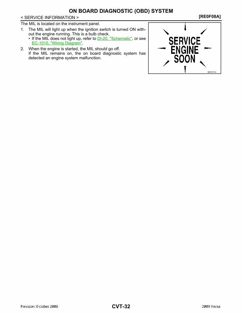
[RE0F08A]ON BOARD DIAGNOSTIC (OBD) SYSTEM
< SERVICE INFORMATION >The MIL is located on the instrument panel.1. The MIL will light up when the ignition switch is turned ON with-
out the engine running. This is a bulb check.• If the MIL does not light up, refer to DI-20, "Schematic", or see
EC-1010, "Wiring Diagram".2. When the engine is started, the MIL should go off.
If the MIL remains on, the on board diagnostic system hasdetected an engine system malfunction.
SEF217U
CVT-32

TROUBLE DIAGNOSIS[RE0F08A]
D
E
F
G
H
I
J
K
L
M
A
B
VT
N
O
P
< SERVICE INFORMATION >
C
TROUBLE DIAGNOSISDTC Inspection Priority Chart INFOID:0000000004666880
If some DTCs are displayed at the same time, perform inspections one by one based on the following prioritychart.NOTE:If DTC “U1000 CAN COMM CIRCUIT” is displayed with other DTCs, first perform the trouble diagnosisfor “DTC U1000 CAN COMMUNICATION LINE”. Refer to CVT-60 .
Fail-Safe INFOID:0000000004666881
The TCM has an electrical fail-safe mode. This mode makes it possible to operate even if there is an error in amain electronic control input/output signal circuit.
FAIL-SAFE FUNCTION If any malfunction occurs in a sensor or solenoid, this function controls the CVT to make driving possible.Output Speed Sensor (Secondary Speed Sensor)The shift pattern is changed in accordance with throttle position when an unexpected signal is sent from theoutput speed sensor (secondary speed sensor) to the TCM. The overdrive-off mode is inhibited, and the tran-saxle is put in “D”.Input Speed Sensor (Primary Speed Sensor)The shift pattern is changed in accordance with throttle position and secondary speed (vehicle speed) whenan unexpected signal is sent from the input speed sensor (primary speed sensor) to the TCM. The sport modeis inhibited, and the transaxle is put in “D”.PNP SwitchIf an unexpected signal is sent from the PNP switch to the TCM, the transaxle is put in “D”. CVT Fluid Temperature SensorIf an unexpected signal is sent from the CVT fluid temperature sensor to the TCM, the gear ratio in use beforereceiving the unexpected signal is maintained or the gear ratio is controlled to keep engine speed under 3500rpm.Transmission Fluid Pressure Sensor A (Secondary Pressure Sensor)• If an unexpected signal is sent from the transmission fluid pressure sensor A (secondary pressure sensor) to
the TCM, the secondary pressure feedback control is stopped and the offset value obtained before the non-standard condition occurs is used to control line pressure.
• If transmission fluid pressure sensor A (secondary pressure sensor) error signal is input to TCM, secondarypressure feedback control stops, but line pressure is controlled normally.
Pressure Control Solenoid A (Line Pressure Solenoid)If an unexpected signal is sent from the solenoid to the TCM, the pressure control solenoid A (line pressuresolenoid) is turned OFF to achieve the maximum fluid pressure.Pressure Control Solenoid B (Secondary Pressure Solenoid)If an unexpected signal is sent from the solenoid to the TCM, the pressure control solenoid B (secondary pres-sure solenoid) is turned OFF to achieve the maximum fluid pressure.Torque Converter Clutch SolenoidIf an unexpected signal is sent from the solenoid to the TCM, the torque converter clutch solenoid is turnedOFF to cancel the lock-up.Step MotorIf an unexpected signal is sent from the step motor to the TCM, the step motor coil phases “A” through “D” areall turned OFF to hold the gear ratio used right before the non-standard condition occurred.CVT Lock-up Select Solenoid
Priority Detected items (DTC)
1 U1000 CAN communication line
2 Except above
CVT-33

[RE0F08A]TROUBLE DIAGNOSIS
< SERVICE INFORMATION >If an unexpected signal is sent from the solenoid to the TCM, the CVT lock-up select solenoid is turned OFF tocancel the lock-up.TCM Power Supply (Memory Back-up)Transaxle assembly is protected by limiting the engine torque when the memory back-up power supply (forcontrolling) from the battery is not supplied to TCM. Normal statues is restored when turning the ignition switchOFF to ON after the normal power supply.
How to Perform Trouble Diagnosis for Quick and Accurate Repair INFOID:0000000004666882
INTRODUCTIONThe TCM receives a signal from the vehicle speed sensor, PNP switch and provides shift control or lock-upcontrol via CVT solenoid valves.The TCM also communicates with the ECM by means of a signalsent from sensing elements used with the OBD-related parts of theCVT system for malfunction-diagnostic purposes. The TCM is capa-ble of diagnosing malfunctioning parts while the ECM can store mal-functions in its memory.Input and output signals must always be correct and stable in theoperation of the CVT system. The CVT system must be in goodoperating condition and be free of valve seizure, solenoid valve mal-function, etc.
It is much more difficult to diagnose an error that occurs intermit-tently rather than continuously. Most intermittent errors are causedby poor electric connections or improper wiring. In this case, carefulchecking of suspected circuits may help prevent the replacement ofgood parts.A visual check only may not find the cause of the errors. A road testwith CONSULT-III (or GST) or a circuit tester connected should beperformed. Follow the "WORK FLOW" .
Before undertaking actual checks, take a few minutes to talk with acustomer who approaches with a driveability complaint. The cus-tomer can supply good information about such errors, especiallyintermittent ones. Find out what symptoms are present and underwhat conditions they occur. A “DIAGNOSTIC WORKSHEET” asshown on the example (Refer to "Diagnostic Worksheet Chart" )should be used.Start your diagnosis by looking for “conventional” errors first. This willhelp troubleshoot driveability errors on an electronically controlledengine vehicle.Also check related Service bulletins.
WORK FLOWA good understanding of the malfunction conditions can make troubleshooting faster and more accurate.In general, each customer feels differently about a malfunction. It is important to fully understand the symp-toms or conditions for a customer complaint.Make good use of the two sheets provided, "Information From Customer" and "Diagnostic Worksheet Chart" ,to perform the best troubleshooting possible.Work Flow Chart
SAT631IB
SAT632I
SEF234G
CVT-34

TROUBLE DIAGNOSIS[RE0F08A]
D
E
F
G
H
I
J
K
L
M
A
B
VT
N
O
P
< SERVICE INFORMATION >
C
DIAGNOSTIC WORKSHEETInformation From Customer
KEY POINTS• WHAT..... Vehicle & CVT model• WHEN..... Date, Frequencies• WHERE..... Road conditions• HOW..... Operating conditions, Symptoms
*1. "Information From Customer" *2. "DIAGNOSTIC WORKSHEET" *3. CVT-33*4. CVT-40 *5. CVT-40, CVT-40 *6. CVT-44*7. CVT-51 *8. CVT-30 *9. CVT-33*10. CVT-60 *11. CVT-145 *12. CVT-153*13. CVT-30 *14. CVT-60 *15. CVT-145*16. EC-542
AWDIA0189GB
CVT-35

[RE0F08A]TROUBLE DIAGNOSIS
< SERVICE INFORMATION >
Diagnostic Worksheet Chart
Customer name MR/MS Model & Year VIN
Trans. Model Engine Mileage
malfunction Date Manuf. Date In Service Date
Frequency Continuous Intermittent ( times a day)
Symptoms Vehicle does not move. ( Any position Particular position)
No shift
Lock-up malfunction
Shift shock or slip ( N → D N → R Lock-up Any drive position)
Noise or vibration
No pattern select
Others( )
Malfunction indicator lamp (MIL) Continuously lit Not lit
1 Read the item on cautions concerning fail-safe and understand the customer's complaint. CVT-33
2
CVT fluid inspection
CVT-40 Leak (Repair leak location.) State Amount
3
Stall test and line pressure test
CVT-40, CVT-40
Stall test
Torque converter one-way clutch Reverse brake Forward clutch Steel belt
Engine Line pressure low Primary pulley Secondary pulley
Line pressure inspection - Suspected part:
CVT-36
TROUBLE DIAGNOSIS[RE0F08A]
D
E
F
G
H
I
J
K
L
M
A
B
VT
N
O
P
< SERVICE INFORMATION >
C
4
Perform road test. CVT-44
4-1.
Check before engine is started CVT-45
CVT-155, "O/D OFF Indicator Lamp Does Not Come On" Perform self-diagnosis. Enter checks for detected items. CVT-51
CVT-60CVT-64CVT-67CVT-69CVT-75CVT-80CVT-84CVT-89CVT-91CVT-92CVT-97CVT-99CVT-104CVT-106CVT-108CVT-113CVT-117CVT-119CVT-123CVT-125CVT-129CVT-131CVT-133CVT-135CVT-136CVT-141CVT-145
4-2.
Check at idle CVT-45
CVT-157, "Engine Cannot Be Started in "P" and "N" Position"CVT-157, "In "P" Position, Vehicle Moves Forward or Backward When Pushed"CVT-158, "In "N" Position, Vehicle Moves"CVT-158, "Large Shock "N" → "R" Position"CVT-159, "Vehicle Does Not Creep Backward in "R" Position"CVT-160, "Vehicle Does Not Creep Forward in "D" or "L" Position"
CVT-37

[RE0F08A]TROUBLE DIAGNOSIS
< SERVICE INFORMATION >
4 4-3.
Cruise test CVT-47
CVT-161, "Vehicle Speed Does Not Change in "L" Position"CVT-162, "Vehicle Speed Does Not Change in overdrive-off mode"CVT-163, "Vehicle Speed Does Not Change in "D" Position"CVT-163, "Vehicle Does Not Decelerate by Engine Brake" perform self-diagnosis. Enter checks for detected items. CVT-51
CVT-60CVT-64CVT-67CVT-69CVT-75CVT-80CVT-84CVT-89CVT-91CVT-92CVT-97CVT-99CVT-104CVT-106CVT-108CVT-113CVT-117CVT-119CVT-123CVT-125CVT-129CVT-131CVT-133CVT-135CVT-136CVT-141CVT-145
5 Inspect each system for items found to be NG in the self-diagnosis and repair or replace the malfunctioning parts.
6 Perform all road tests and enter the checks again for the required items. CVT-44
7 For any remaining NG items, perform the “diagnosis procedure” and repair or replace the malfunctioning parts.
8 Erase the results of the self-diagnosis from the TCM. CVT-30, CVT-30
CVT-38

TROUBLE DIAGNOSIS[RE0F08A]
D
E
F
G
H
I
J
K
L
M
A
B
VT
N
O
P
< SERVICE INFORMATION >
C
CVT Electrical Parts Location INFOID:0000000004666883
1. O/D OFF indicator lamp 2. Shift position indicator 3. Accelerator pedal position sensor4. CVT unit harness connector 5. Fuel door release 6. TCM7. Overdrive control switch
BCIA0033E
CVT-39

[RE0F08A]TROUBLE DIAGNOSIS
< SERVICE INFORMATION >Circuit Diagram INFOID:0000000004666884
Inspections before Trouble Diagnosis INFOID:0000000004666885
CVT FLUID CHECKFluid Leakage and Fluid Level Check
AADWA0046GB
CVT-40

TROUBLE DIAGNOSIS[RE0F08A]
D
E
F
G
H
I
J
K
L
M
A
B
VT
N
O
P
< SERVICE INFORMATION >
C
• Inspect for fluid leakage and check the fluid level. Refer to CVT-17, "Checking CVT Fluid" .Fluid Condition CheckInspect the fluid condition.
STALL TESTStall Test Procedure1. Inspect the amount of engine oil. Replenish the engine oil if necessary.2. Drive for about 10 minutes to warm up the vehicle so that the
CVT fluid temperature is 50 to 80°C (122 to 176°F). Inspect theamount of CVT fluid. Replenish if necessary.
3. Securely engage the parking brake so that the tires do not turn.4. Install a tachometer where it can be seen by driver during test.
• It is good practice to mark the point of specified enginerpm on indicator.
5. Start engine, apply foot brake, and place selector lever in “D”position.
Fluid status Conceivable cause Required operation
Varnished (viscous varnish state)
Clutch, brake scorched
Replace the CVT fluid and check the CVT main unit and the vehicle for malfunctions (wire harnesses, cool-er pipes, etc.)
Milky white or cloudy Water in the fluid Replace the CVT fluid and check for
places where water is getting in.
Large amount of metal powder mixed in
Unusual wear of sliding parts within CVT
Replace the CVT fluid and check for improper operation of the CVT. SAT638A
SAT647B
SAT513G
SAT775B
CVT-41

[RE0F08A]TROUBLE DIAGNOSIS
< SERVICE INFORMATION >6. While holding down the foot brake, gradually press down the
accelerator pedal.7. Quickly read off the stall speed, and then quickly remove your
foot from the accelerator pedal.CAUTION:Do not hold down the accelerator pedal for more than 5 sec-onds during this test.
8. Move the selector lever to the “N” position.9. Cool down the CVT fluid.
CAUTION:Run the engine at idle for at least 1 minute.
10. Repeat steps 6 through 9 with selector lever in “R” position.
Judgement Stall Test
O: Stall speed within standard value position.H: Stall speed is higher than standard value.L: Stall speed is lower than standard value.
LINE PRESSURE TESTLine Pressure Test Port
Line Pressure Test Procedure1. Inspect the amount of engine oil and replenish if necessary.2. Drive the car for about 10 minutes to warm it up so that the CVT fluid reaches in the range of 50 to 80°C
(122 to 176°F), then inspect the amount of CVT fluid and replenish if necessary.NOTE:
Stall speed: 2,600 - 3,150 rpm
SAT514G
SAT771B
Selector lever positionExpected problem location
“D” “R”
Stall rotation
H O • Forward clutch
O H • Reverse brake
L L • Engine and torque converter one-way clutch
H H
• Line pressure low• Primary pulley• Secondary pulley• Steel belt
SCIA6184E
CVT-42

TROUBLE DIAGNOSIS[RE0F08A]
D
E
F
G
H
I
J
K
L
M
A
B
VT
N
O
P
< SERVICE INFORMATION >
C
The CVT fluid temperature rises in the range of 50 - 80°C (122 - 176°F) during 10 minutes of driving.3. After warming up CVT, remove the oil pressure detection plug and install the oil pressure gauge [special
service tool: - (OTC3492)].CAUTION:When using the oil pressure gauge, be sure to use the O-ring attached to the oil pressure detec-tion plug.
4. Securely engage the parking brake so that the tires do not turn.
5. Start the engine, and then measure the line pressure at both idleand the stall speed.CAUTION:• Keep the brake pedal pressed all the way down during
measurement.• When measuring the line pressure at the stall speed, refer
to "STALL TEST" . 6. After the measurements are complete, install the oil pressure
detection plug and tighten to the specified torque below.
CAUTION:• Do not reuse O-ring.• Apply CVT fluid to O-ring.
Line Pressure
*: Reference values
Judgement of Line Pressure Test
SAT513G
: 7.5 N·m (0.77 kg-m, 66 in-lb) SAT493G
Engine speed Line pressure kPa (kg/cm2 , psi)
“R”, “D” and “L” positions
At idle 650 (6.63, 94.3)
At stall 4,250 (43.35, 616.3)*
CVT-43

[RE0F08A]TROUBLE DIAGNOSIS
< SERVICE INFORMATION >
Road Test INFOID:0000000004666886
DESCRIPTION• The purpose of the test is to determine overall performance of CVT
and analyze causes of problems.• The road test consists of the following three parts:1. “Check Before Engine Is Started”CVT-45 .2. “Check at Idle”CVT-45 .3. “Cruise Test”CVT-47 .
Judgement Possible cause
Idle speed
Low for all positions (“P”, “R”, “N”, “D”, “L”)
Possible causes include malfunctions in the pressure supply system and low oil pump output.For example• Oil pump wear• Pressure regulator valve or plug sticking or spring fatigue• Oil strainer ⇒ oil pump ⇒ pressure regulator valve passage oil leak• Engine idle speed too low
Only low for a specific position
Possible causes include an oil pressure leak in a passage or device related to the position after the pressure is distributed by the manual valve.
High
Possible causes include a sensor malfunction or malfunction in the line pressure adjustment function.For example• Accelerator pedal position signal malfunction• CVT fluid temperature sensor malfunction• Pressure control solenoid A (line pressure solenoid) malfunction (sticking in OFF state, filter
clog, cut line)• Pressure regulator valve or plug sticking
Stall speed
Line pressure does not rise higher than the line pressure for idle.
Possible causes include a sensor malfunction or malfunction in the pressure adjustment func-tion.For example• Accelerator pedal position signal malfunction• TCM malfunction• Pressure control solenoid A (line pressure solenoid) malfunction (shorting, sticking in ON
state)• Pressure regulator valve or plug sticking
The pressure rises, but does not enter the standard position.
Possible causes include malfunctions in the pressure supply system and malfunction in the pres-sure adjustment function.For example• Accelerator pedal position signal malfunction• Pressure control solenoid A (line pressure solenoid) malfunction (sticking, filter clog)• Pressure regulator valve or plug sticking
Only low for a specific position
Possible causes include an oil pressure leak in a passage or device related to the position after the pressure is distributed by the manual valve.
SAT786A
CVT-44

TROUBLE DIAGNOSIS[RE0F08A]
D
E
F
G
H
I
J
K
L
M
A
B
VT
N
O
P
< SERVICE INFORMATION >
C
• Before road test, familiarize yourself with all test procedures anditems to check.
• Perform tests on all items until specified symptom is found. Trou-bleshoot items which check out No Good after road test.
CONSULT-III START PROCEDURE• Using CONSULT-III, perform a cruise test and record the result.• Print the result and ensure that shifts and lock-ups take place as per Shift Schedule.1. Touch “DATA MONITOR” on “SELECT DIAG MODE” screen.
2. Touch “MAIN SIGNALS” to set recording condition.
3. See “Numerical Display”, “Barchart Display” or “Line Graph Display”.
4. Touch “START”.
5. When performing cruise test. Refer to CVT-47, "Cruise Test" .
6. After finishing cruise test part, touch “RECORD”.
7. Touch “STORE”.
8. Touch “BACK”.
9. Touch “DISPLAY”.
10. Touch “PRINT”.
11. Check the monitor data printed out.
Check before Engine Is Started INFOID:0000000004666887
1.CHECK O/D OFF INDICATOR LAMP
1. Park vehicle on flat surface.2. Move selector lever to “P” position.3. Turn ignition switch OFF. Wait at least 5 seconds.4. Turn ignition switch ON. (Do not start engine.)Does O/D OFF indicator lamp come on for about 2 seconds?YES >> 1. Turn ignition switch OFF.
2. Perform self-diagnosis and note NG items.Refer to CVT-51, "CONSULT-III Function (TRANSMISSION)" .
3. Go to CVT-45, "Check at Idle" .NO >> Stop “Road Test”. Go to CVT-155, "O/D OFF Indicator Lamp Does Not Come On" .
Check at Idle INFOID:0000000004666888
1.CHECK STARTING THE ENGINE
1. Park vehicle on flat surface.2. Move selector lever to “P” or “N” position.3. Turn ignition switch OFF.4. Turn ignition switch START.Is engine started?
SAT496G
CVT-45

[RE0F08A]TROUBLE DIAGNOSIS
< SERVICE INFORMATION >YES >> GO TO 2.NO >> Stop “Road Test”. Mark the box on the CVT-34, "How to Perform Trouble Diagnosis for Quick and
Accurate Repair" . Go to CVT-157, "Engine Cannot Be Started in "P" and "N" Position" .2.CHECK STARTING THE ENGINE
1. Turn ignition switch ON.2. Move selector lever to “D”, “L” or “R” position.3. Turn ignition switch START.Is engine started?YES >> Stop “Road Test”. Mark the box on the CVT-34, "How to Perform Trouble Diagnosis for Quick and
Accurate Repair" . Go to CVT-157, "Engine Cannot Be Started in "P" and "N" Position" .NO >> GO TO 3.
3.CHECK “P” POSITION FUNCTION
1. Move selector lever to “P” position.2. Turn ignition switch OFF.3. Release parking brake.4. Push vehicle forward or backward.5. Apply parking brake.Does vehicle move when it is pushed forward or backward?YES >> Mark the box CVT-157, "In "P" Position, Vehicle Moves Forward or Backward When Pushed" on
the CVT-34, "How to Perform Trouble Diagnosis for Quick and Accurate Repair" . Continue “RoadTest”.
NO >> GO TO 4.4.CHECK “N” POSITION FUNCTION
1. Start engine.2. Move selector lever to “N” position.3. Release parking brake.Does vehicle move forward or backward?YES >> Mark the box CVT-158, "In "N" Position, Vehicle Moves" on the CVT-34, "How to Perform Trouble
Diagnosis for Quick and Accurate Repair" . Continue “Road Test”.NO >> GO TO 5.
5.CHECK SHIFT SHOCK
1. Apply foot brake.2. Move selector lever to “R” position.Is there large shock when changing from “N” to “R” position?YES >> Mark the box CVT-158, "Large Shock "N" → "R" Position" on the CVT-34, "How to Perform Trou-
ble Diagnosis for Quick and Accurate Repair" . Continue “Road Test”.NO >> GO TO 6.
6.CHECK “R” POSITION FUNCTION
Release foot brake for several seconds.Does vehicle creep backward when foot brake is released?YES >> GO TO 7.NO >> Mark the box CVT-159, "Vehicle Does Not Creep Backward in "R" Position" on the CVT-34, "How
to Perform Trouble Diagnosis for Quick and Accurate Repair" . Continue “Road Test”.7.CHECK “D”, “L” POSITIONS FUNCTION
Move selector lever to “D” and “L” positions and check if vehicle creeps forward.Does vehicle creep forward in all positions?YES >> Go to CVT-47, "Cruise Test" .NO >> Stop “Road Test”. Mark the box on the CVT-34, "How to Perform Trouble Diagnosis for Quick and
Accurate Repair" . Go to CVT-160, "Vehicle Does Not Creep Forward in "D" or "L" Position" .
CVT-46

TROUBLE DIAGNOSIS[RE0F08A]
D
E
F
G
H
I
J
K
L
M
A
B
VT
N
O
P
< SERVICE INFORMATION >
C
Cruise Test INFOID:0000000004666889
1.CHECK VEHICLE SPEED WHEN SHIFTING GEARS — PART 1
1. Drive vehicle for approximately 10 minutes to warm engine oil and CVT fluid up to operating temperature.
2. Park vehicle on flat surface.3. Move selector lever to “P” position.4. Start engine.5. Move selector lever to “L” position. 6. Accelerate vehicle to 2/8-way throttle depressing accelerator
pedal constantly. Read vehicle speed and engine speed. Refer to CVT-49,
"Vehicle Speed When Shifting Gears" .OK or NGOK >> GO TO 2.NG >> Mark the box of CVT-161, "Vehicle Speed Does Not
Change in "L" Position" on the CVT-34, "How to Per-form Trouble Diagnosis for Quick and Accurate Repair" .Continue “Road Test”.
2.CHECK VEHICLE SPEED WHEN SHIFTING GEARS — PART 2
1. Park vehicle on flat surface.2. Move selector lever to “D” position. 3. Push overdrive control switch. (O/D OFF indicator lamp is on.)4. Accelerate vehicle to 2/8-way throttle depressing accelerator
pedal constantly. Read vehicle speed and engine speed. Refer to CVT-49,
"Vehicle Speed When Shifting Gears" .OK or NGOK >> GO TO 3.NG >> Mark the box of CVT-162, "Vehicle Speed Does Not
Change in overdrive-off mode" on the CVT-34, "How toPerform Trouble Diagnosis for Quick and AccurateRepair" . Continue “Road Test”.
3.CHECK VEHICLE SPEED WHEN SHIFTING GEARS — PART 3
1. Park vehicle on flat surface.2. Move selector lever to “D” position. 3. Push overdrive control switch. (O/D OFF indicator lamp is off.)4. Accelerate vehicle to 2/8-way throttle depressing accelerator
pedal constantly. Read vehicle speed and engine speed. Refer to CVT-49,
"Vehicle Speed When Shifting Gears" .OK or NGOK >> GO TO 4.NG >> Mark the box of CVT-163, "Vehicle Speed Does Not
Change in "D" Position" on the CVT-34, "How to Per-form Trouble Diagnosis for Quick and Accurate Repair" .Continue “Road Test”.
4.CHECK VEHICLE SPEED WHEN SHIFTING GEARS — PART 4
1. Park vehicle on flat surface.2. Move selector lever to “L” position.
CVT fluid operating temperature: 50 - 80°C (122 - 176°F)
SCIA6644E
SCIA6644E
SCIA6644E
CVT-47

[RE0F08A]TROUBLE DIAGNOSIS
< SERVICE INFORMATION >3. Accelerate vehicle to full depression depressing accelerator
pedal constantly. Read vehicle speed and engine speed. Refer to CVT-49,
"Vehicle Speed When Shifting Gears" .OK or NGOK >> GO TO 5.NG >> Mark the box of CVT-161, "Vehicle Speed Does Not
Change in "L" Position" on the CVT-34, "How to Per-form Trouble Diagnosis for Quick and Accurate Repair" .Continue “Road Test”.
5.CHECK VEHICLE SPEED WHEN SHIFTING GEARS — PART 5
1. Park vehicle on flat surface.2. Move selector lever to “D” position. 3. Push overdrive control switch. (O/D OFF indicator lamp is on.)4. Accelerate vehicle to full depressing depressing accelerator
pedal constantly. Read vehicle speed and engine speed. Refer to CVT-49,
"Vehicle Speed When Shifting Gears" .OK or NGOK >> GO TO 6.NG >> Mark the box of CVT-162, "Vehicle Speed Does Not
Change in overdrive-off mode" on the CVT-34, "How toPerform Trouble Diagnosis for Quick and AccurateRepair" . Continue “Road Test”.
6.CHECK VEHICLE SPEED WHEN SHIFTING GEARS — PART 6
1. Park vehicle on flat surface.2. Move selector lever to “D” position.3. Push overdrive control switch. (O/D OFF indicator lamp is off.)4. Accelerate vehicle to full depression depressing accelerator
pedal constantly. Read vehicle speed and engine speed. Refer to CVT-49,
"Vehicle Speed When Shifting Gears" .OK or NGOK >> GO TO 7.NG >> Mark the box of CVT-163, "Vehicle Speed Does Not
Change in "D" Position" on the CVT-34, "How to Per-form Trouble Diagnosis for Quick and Accurate Repair" .Continue “Road Test”.
7.CHECK ENGINE BRAKE FUNCTION — PART 1
1. Release accelerator pedal.2. Check engine brake. (O/D OFF indicator lamp is off.)Does engine braking effectively reduce speed in “D” position?YES >> GO TO 8.NO >> Mark the box of CVT-163, "Vehicle Does Not Decelerate by Engine Brake" on the CVT-34, "How
to Perform Trouble Diagnosis for Quick and Accurate Repair" . Continue “Road Test”.8.CHECK ENGINE BRAKE FUNCTION — PART 2
1. Push overdrive control switch. (O/D OFF indicator lamp is on.)2. Check engine brake.Does engine braking effectively reduce speed in “D” position?YES >> GO TO 9.NO >> Mark the box of CVT-163, "Vehicle Does Not Decelerate by Engine Brake" on the CVT-34, "How
to Perform Trouble Diagnosis for Quick and Accurate Repair" . Continue “Road Test”.
SCIA4366E
SCIA4366E
SCIA4366E
CVT-48

TROUBLE DIAGNOSIS[RE0F08A]
D
E
F
G
H
I
J
K
L
M
A
B
VT
N
O
P
< SERVICE INFORMATION >
C
9.CHECK ENGINE BRAKE FUNCTION — PART 3
1. Move selector lever to “L” position.2. Check engine brake.Does engine braking effectively reduce speed in “L” position?YES >> 1. Stop the vehicle.
2. Perform self-diagnosis. Refer to CVT-51, "CONSULT-III Function (TRANSMISSION)" .NO >> Mark the box of CVT-163, "Vehicle Does Not Decelerate by Engine Brake" on the CVT-34, "How
to Perform Trouble Diagnosis for Quick and Accurate Repair" . Then continue trouble diagnosis.
Vehicle Speed When Shifting Gears INFOID:0000000004666890
Numerical value data are reference values.
CAUTION:Lock-up clutch is engaged when vehicle speed is approximately 18 km/h (11 MPH) to 90 km/h (56 MPH).
TCM Terminal and Reference Value INFOID:0000000004666891
TCM HARNESS CONNECTOR TERMINAL LAYOUT
TERMINALS AND REFERENCE VALUES FOR TCMData are reference values and are measured between each terminal and ground.
Engine type Throttle position Shift patternEngine speed (rpm)
At 40 km/h (25 MPH) At 60 km/h (37 MPH)
MR18DE
8/8“D” position
Overdrive-off mode“L” position
3,600 - 4,500 4,400 - 5,300
2/8
“D” position 1,300 - 3,100 1,400 - 3,500
Overdrive-off mode 2,200 - 3,000 2,800 - 3,600
“L” position 3,200 - 4,100 3,900 - 4,800
WCIA0717E
Terminal Wire color Item Condition Data (Approx.)
1 GR
Pressure control solenoid valve A (Line pressure solenoid valve)
and
Release your foot from the accelerator pedal. 5.0 - 7.0 V
Press the accelerator pedal all the way down. 1.0 - 3.0 V
2 LG
Pressure control solenoid valve B (Secondary pressure sole-noid valve)
Release your foot from the accelerator pedal. 5.0 - 7.0 V
Press the accelerator pedal all the way down. 3.0 - 4.0 V
3 SBTorque converter clutch solenoid valve
When vehi-cle cruises in “D” position.
When CVT performs lock-up. 6.0 V
When CVT does not perform lock-up. 1.0 V
CVT-49

[RE0F08A]TROUBLE DIAGNOSIS
< SERVICE INFORMATION >
4 BR Lock-up select solenoid valve
Selector lever in “P” and “N” positions Battery voltage
Wait at least for 5 seconds with the selector lever in “R”, “D” and “L” positions 0 V
5 L CAN-H — —
6 P CAN-L — —
8 V Back-up lamp relay
Selector lever in “R” position. 0 V
Selector lever in other positions. Battery voltage
10 R Power supply
— Battery voltage
— 0 V
11 L Step motor A Within 2 seconds after ignition switch ON, the time measurement by using the pulse width measurement function (Hi level) of CONSULT-III.*1*1: A circuit tester cannot be used to test this item.
30.0 msec
12 Y Step motor B 10.0 msec
13 G ROM assembly — —
14 Y ROM assembly — —
15 G ROM assembly — —
19 R Power supply
— Battery voltage
— 0 V
20 W Step motor C Within 2 seconds after ignition switch ON, the time measurement by using the pulse width measurement function (Hi level) of CONSULT-III.*1*1: A circuit tester cannot be used to test this item.
30.0 msec
21 P Step motor D 10.0 msec
24 BR Starter relaySelector lever in “N” and “P”positions. Battery voltage
Selector lever in other positions. 0 V
25 B Ground Always 0 V
27 GR PNP switch 1Selector lever in “R”, “N” and “D” positions. 0 V
Selector lever in “P” and “L” positions. Battery voltage
28 YPower supply(memory back-up)
Always Battery voltage
29 R
Output speed sensor (Second-ary speed sen-sor)
When driving [“D” position, 20 km/h (12 MPH)]. 570 Hz
31 LG K-LINE — —
Terminal Wire color Item Condition Data (Approx.)
CVT-50

TROUBLE DIAGNOSIS[RE0F08A]
D
E
F
G
H
I
J
K
L
M
A
B
VT
N
O
P
< SERVICE INFORMATION >
C
CONSULT-III Function (TRANSMISSION) INFOID:0000000004666892
CONSULT-III can display each diagnostic item using the diagnostic test modes shown below.
FUNCTION
32 Y PNP switch 3 (monitor)
Selector lever in “D” and “L” positions. 0 V
Selector lever in “P”, “R” and “N” positions. 8.0 V - Battery voltage
34 SB PNP switch 2Selector lever in “N”, “D” and “L” positions. 0 V
Selector lever in “P” and “R” positions. 10.0 V - Battery voltage
35 W PNP switch 3Selector lever in “D” and “L” positions. 0 V
Selector lever in “P”, “R” and “N” positions. 8.0 V - Battery voltage
36 W PNP switch 4Selector lever in “R” and “D” positions. 0 V
Selector lever in “P”, “N” and “L” positions. 10.0 V - Battery voltage
37 L
Transmission fluid pressure sensor A (Sec-ondary pressure sensor)
and “N” position idle 1.0 V
38 VInput speed sen-sor (Primary speed sensor)
When driving [“L” position, 20 km/h (12 MPH)]. 1000 Hz
41 G
Transmission fluid pressure sensor B (Prima-ry pressure sen-sor)
and “N” position idle 0.7 V
42 LG Sensor ground Always 0 V
46 O Sensor power
— 5.0 V
— 0 V
47 G CVT fluid tem-perature sensor
When CVT fluid temperature is 20°C (68°F) 2.0 V
When CVT fluid temperature is 80°C (176°F) 1.0 V
48 B Ground Always 0 V
Terminal Wire color Item Condition Data (Approx.)
Diagnostic test mode Function
Work support This mode enables a technician to adjust some devices faster and more accurately by following the in-dications on CONSULT-III.
Self-diagnostic results Self-diagnostic results can be read and erased quickly.
Data monitor Input/Output data in the TCM can be read.
CVT-51
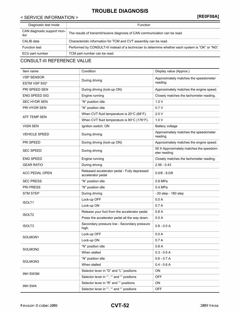
[RE0F08A]TROUBLE DIAGNOSIS
< SERVICE INFORMATION >
CONSULT-III REFERENCE VALUE
CAN diagnostic support mon-itor The results of transmit/receive diagnosis of CAN communication can be read.
CALIB data Characteristic information for TCM and CVT assembly can be read.
Function test Performed by CONSULT-III instead of a technician to determine whether each system is “OK” or “NG”.
ECU part number TCM part number can be read.
Diagnostic test mode Function
Item name Condition Display value (Approx.)
VSP SENSORDuring driving Approximately matches the speedometer
reading.ESTM VSP SIG*
PRI SPEED SEN During driving (lock-up ON) Approximately matches the engine speed.
ENG SPEED SIG Engine running Closely matches the tachometer reading.
SEC HYDR SEN “N” position idle 1.0 V
PRI HYDR SEN “N” position idle 0.7 V
ATF TEMP SENWhen CVT fluid temperature is 20°C (68°F). 2.0 V
When CVT fluid temperature is 80°C (176°F). 1.0 V
VIGN SEN Ignition switch: ON Battery voltage
VEHICLE SPEED During driving Approximately matches the speedometer reading.
PRI SPEED During driving (lock-up ON) Approximately matches the engine speed.
SEC SPEED During driving 50 X Approximately matches the speedom-eter reading.
ENG SPEED Engine running Closely matches the tachometer reading.
GEAR RATIO During driving 2.56 - 0.43
ACC PEDAL OPEN Released accelerator pedal - Fully depressed accelerator pedal 0.0/8 - 8.0/8
SEC PRESS “N” position idle 0.8 MPa
PRI PRESS “N” position idle 0.4 MPa
STM STEP During driving −20 step - 180 step
ISOLT1Lock-up OFF 0.0 A
Lock-up ON 0.7 A
ISOLT2Release your foot from the accelerator pedal. 0.8 A
Press the accelerator pedal all the way down. 0.0 A
ISOLT3 Secondary pressure low - Secondary pressure high. 0.8 - 0.0 A
SOLMON1Lock-up OFF 0.0 A
Lock-up ON 0.7 A
SOLMON2“N” position idle 0.8 A
When stalled 0.3 - 0.6 A
SOLMON3“N” position idle 0.6 - 0.7 A
When stalled 0.4 - 0.6 A
INH SW3MSelector lever in “D” and “L” positions ON
Selector lever in “”, “” and “” positions OFF
INH SW4Selector lever in “R” and “” positions ON
Selector lever in “”, “” and “” positions OFF
CVT-52

TROUBLE DIAGNOSIS[RE0F08A]
D
E
F
G
H
I
J
K
L
M
A
B
VT
N
O
P
< SERVICE INFORMATION >
C
*: Models without ABS does not indicate.
WORK SUPPORT MODEDisplay Item List
INH SW3Selector lever in “D” and “L” positions ON
Selector lever in “”, “” and “” positions OFF
INH SW2Selector lever in “”, “” and “” positions ON
Selector lever in “P” and “” positions OFF
INH SW1Selector lever in “”, “” and “” positions ON
Selector lever in “P” and “L” positions OFF
BRAKE SWDepressed brake pedal ON
Released brake pedal OFF
FULL SWFully depressed accelerator pedal ON
Released accelerator pedal OFF
IDLE SWReleased accelerator pedal ON
Fully depressed accelerator pedal OFF
SPORT MODE SWWhile pushing overdrive cancel switch ON
Other conditions OFF
INDDRNGSelector lever in “D” position ON
Selector lever in other positions OFF
INDLRNGSelector lever in “L” position ON
Selector lever in other positions OFF
INDNRNGSelector lever in “N” position ON
Selector lever in other positions OFF
INDRRNGSelector lever in “R” position ON
Selector lever in other positions OFF
INDPRNGSelector lever in “P” position ON
Selector lever in other positions OFF
SMCOIL D
During driving Changes ON ⇔ OFF.SMCOIL C
SMCOIL B
SMCOIL A
LUSEL SOL OUTSelector lever in “P” and “N” positions ON
Wait at least for 5 seconds with the selector lever in “R”, “D” and “L” positions OFF
STRTR RLY OUTSelector lever in “P” and “N” positions ON
Selector lever in other positions OFF
STRTR RLY MONSelector lever in “P” and “N” positions ON
Selector lever in other positions OFF
RANGE
Selector lever in “N” or “P” position. N·P
Selector lever in “R” position. R
Selector lever in “D” position. D
Selector lever in “L” position. L
Item name Condition Display value (Approx.)
CVT-53

[RE0F08A]TROUBLE DIAGNOSIS
< SERVICE INFORMATION >
Engine Brake Adjustment
CAUTION:Mode of “+1”“0”“-1”“-2”“OFF” can be selected by pressing the “UP”“DOWN” on CONSULT-III screen.However, do not select mode other than “0” and “OFF”. If the “+1” or “-1” or “-2” is selected, thatmight cause the irregular driveability.Check CVT Fluid Deterioration Date
CAUTION:Touch “CLEAR” after changing CVT fluid, and then erase “CVTF DETERIORATION DATE”.
SELF-DIAGNOSTIC RESULT MODEAfter performing self-diagnosis, place check marks for results on the CVT-34, "How to Perform Trouble Diag-nosis for Quick and Accurate Repair" . Reference pages are provided following the items.Display Items List
X: Applicable —: Not applicable
Item name Description
ENGINE BRAKE ADJ. The engine brake level setting can be canceled.
CONFORM CVTF DETERIORTN The CVT fluid deterioration level can be checked.
“ENGINE BRAKE LEVEL”0: Initial set value (Engine brake level control is ac-tivated)OFF: Engine brake level control is deactivated.
“CVTF DETERIORATION DATE”More than 210000:
It is necessary to change CVT fluid.Less than 210000:
It is not necessary to change CVT fluid.
Items (CONSULT-III screen terms) Malfunction is detected when...
TCM self-di-agnosis OBD-III (DTC)
Reference page“TRANSMIS-
SION” with CONSULT-III
MIL indicator lamp*1, “EN-GINE” with
CONSULT-III or GST
CAN COMM CIR-CUIT
When TCM is not transmitting or receiving CAN communica-tion signal for 2 seconds or more U1000 U1000 CVT-60
CONTROL UNIT(CAN)
When detecting error during the initial diagnosis of CAN con-troller of TCM U1010 U1010 CVT-63
STARTER RELAY/CIRC
Is this signal is ON other than in “P” or “N” position, this is judged to be a malfunction(And if it is OFF in “P” or “N” position, this is judged to be a malfunction too)
P0615 — CVT-64
BRAKE SW/CIRC When the brake switch does not switch to ON or OFF P0703 — CVT-67
PNP SW/CIRC • PNP switch 1-4 signals input with impossible pattern• PNP switch 3 monitor terminal open or short circuit P0705 P0705 CVT-69
ATF TEMP SEN/CIRC
During running, the CVT fluid temperature sensor signal volt-age is excessively high or low P0710 P0710 CVT-75
INPUT SPD SEN/CIRC
• Input speed sensor (primary speed sensor) signal is not in-put due to an open circuit
• An unexpected signal is input when vehicle is being drivenP0715 P0715 CVT-80
CVT-54

TROUBLE DIAGNOSIS[RE0F08A]
D
E
F
G
H
I
J
K
L
M
A
B
VT
N
O
P
< SERVICE INFORMATION >
CVEH SPD SEN/CIR AT
• Signal from vehicle speed sensor CVT [Output speed sen-sor (Secondary speed sensor)] not input due to open or short circuit
• Unexpected signal input during running
P0720 P0720 CVT-84
ENGINE SPEED SIG
• TCM does not receive the CAN communication signal from the ECM
• Engine speed is too low while drivingP0725 — CVT-89
BELT DAMG Unexpected gear ratio detected P0730 — CVT-91
TCC SOLENOID/CIRC
Normal voltage not applied to solenoid due to open or short circuit P0740 P0740 CVT-92
A/T TCC S/V FNCTN
• CVT cannot perform lock-up even if electrical circuit is good• TCM detects as irregular by comparing difference value
with slip rotation• There is big difference engine speed and primary speed
when TCM lock-up signal is on
P0744 P0744 CVT-97
L/PRESS SOL/CIRC
• Normal voltage not applied to solenoid due to open or short circuit
• TCM detects as irregular by comparing target value with monitor value
P0745 P0745 CVT-99
PRS CNT SOL/A FCTN
Unexpected gear ratio was detected in the LOW side due to excessively low line pressure P0746 P0746 CVT-104
PRS CNT SOL/B FCTN
Secondary pressure is too high or too low compared with the commanded value while driving P0776 P0776 CVT-106
PRS CNT SOL/B CIRC
• Normal voltage not applied to solenoid due to cut line, short, or the like
• TCM detects as irregular by comparing target value with monitor value
P0778 P0778 CVT-108
TR PRS SENS/A CIRC
Signal voltage of the transmission fluid pressure sensor A (secondary pressure sensor) is too high or too low while driv-ing
P0840 P0840 CVT-113
PRESS SEN/FNCTN
Correlation between the values of the transmission fluid pres-sure sensor A (secondary pressure sensor) and the tranmis-sion fluid pressure sensor B (primary pressure sensor) is out of specification
P0841 — CVT-117
TR PRS SENS/B CIRC
Signal voltage of the transmission fluid pressure sensor B (primary pressure sensor) is too high or too low while driving P0845 P0845 CVT-119
SEC/PRESS DOWN
Secondary fluid pressure is too low compared with the com-manded value while driving P0868 — CVT-123
TCM-POWER SUPPLY
• When the power supply to the TCM is cut OFF, for example because the battery is removed, and the self-diagnosis memory function stops
• This is not a malfunction message (Whenever shutting OFF a power supply to the TCM, this message appears on the screen)
P1701 — CVT-125
TP SEN/CIRC A/T TCM does not receive the proper accelerator pedal position signals (input by CAN communication) from ECM P1705 — CVT-129
ESTM VEH SPD SIG*2
• CAN communication with the ABS actuator and the electric unit (control unit) is malfunctioning
• There is a great difference between the vehicle speed sig-nal from the ABS actuator and the electric unit (control unit), and the vehicle speed sensor signal
P1722 — CVT-131
Items (CONSULT-III screen terms) Malfunction is detected when...
TCM self-di-agnosis OBD-III (DTC)
Reference page“TRANSMIS-
SION” with CONSULT-III
MIL indicator lamp*1, “EN-GINE” with
CONSULT-III or GST
CVT-55

[RE0F08A]TROUBLE DIAGNOSIS
< SERVICE INFORMATION >
*1: Refer to CVT-31, "Malfunction Indicator Lamp (MIL)" .*2: Models without ABS does not indicate.
DATA MONITOR MODEDisplay Items List
X: Standard, —: Not applicable, : Option
CVT SPD SEN/FNCTN
A rotation sensor error is detected because the gear does not change in accordance with the position of the stepping motorCAUTION:One of the “P0720 VEH SPD SEN/CIR AT”, the “P0715 IN-PUT SPD SEN/CIRC” or the “P0725 ENGINE SPEED SIG“ is displayed with the DTC at the same time
P1723 — CVT-133
ELEC TH CON-TROL
The electronically controlled throttle for ECM is malfunction-ing P1726 — CVT-135
LU-SLCT SOL/CIRC
• Normal voltage not applied to solenoid due to cut line, short, or the like
• TCM detects as irregular by comparing target value with monitor value
P1740 P1740 CVT-136
L/PRESS CON-TROL TCM detects the unexpected line pressure P1745 — CVT-140
STEP MOTR CIRC Each coil of the step motor is not energized properly due to an open or a short P1777 P1777 CVT-141
STEP MOTR/FNC There is a great difference between the number of steps for the stepping motor and for the actual gear ratio P1778 P1778 CVT-145
NO DTC IS DE-TECTED: FUR-THER TESTING MAY BE RE-QUIRED
No NG item has been detected X X —
Items (CONSULT-III screen terms) Malfunction is detected when...
TCM self-di-agnosis OBD-III (DTC)
Reference page“TRANSMIS-
SION” with CONSULT-III
MIL indicator lamp*1, “EN-GINE” with
CONSULT-III or GST
Monitored item (Unit)
Monitor item selection
Remarks ECU IN-PUT SIG-
NALS
MAIN SIG-NALS
SELEC-TION FROM MENU
VSP SENSOR (km/h) X — Output speed sensor (secondary speed sensor).
ESTM VSP SIG (km/h) X — Models without ABS does not indicate.
PRI SPEED SEN (rpm) X —
ENG SPEED SIG (rpm) X —
SEC HYDR SEN (V) X —
PRI HYDR SEN (V) X —
ATF TEMP SEN (V) X — CVT fluid temperature sensor
VIGN SEN (V) X —
VEHICLE SPEED (km/h) — X Vehicle speed recognized by the TCM.
PRI SPEED (rpm) — X Primary pulley speed.
SEC SPEED (rpm) — — Secondary pulley speed.
CVT-56

TROUBLE DIAGNOSIS[RE0F08A]
D
E
F
G
H
I
J
K
L
M
A
B
VT
N
O
P
< SERVICE INFORMATION >
C
ENG SPEED (rpm) — X
SLIP REV (rpm) — X Difference between engine speed and primary pulley speed
GEAR RATIO — X
G SPEED (G) — —
ACC PEDAL OPEN (0.0/8) X X
Degree of opening for accelerator recognized by the TCMFor fail-safe operation, the specific value used for control is displayed.
TRQ RTO — —
SEC PRESS (MPa) — X
PRI PRESS (MPa) — X
ATFTEMP COUNT — XMeans CVT fluid temperature. Actual oil temper-ature (°C) cannot be checked unless a numeric value is converted. Refer to CVT-12.
DSR REV (rpm) — —
DGEAR RATIO — —
DSTM STEP (step) — —
STM STEP (step) — X
LU PRS (MPa) — —
LINE PRS (MPa) — —
TGT SEC PRESS (MPa) — —
ISOLT1 (A) — X Torque converter clutch solenoid valve output current
ISOLT2 (A) — X Pressure control solenoid valve A (line pressure solenoid valve) output current
ISOLT3 (A) — X Pressure control solenoid valve B (secondary pressure solenoid valve) output current
SOLMON1 (A) X X Torque converter clutch solenoid valve monitor current
SOLMON2 (A) X X Pressure control solenoid valve A (line pressure solenoid valve) monitor current
SOLMON3 (A) X X Pressure control solenoid valve B (secondary pressure solenoid valve) monitor current
INH SW3M (ON/OFF) X — PNP switch 3 ON-OFF status monitor
INH SW4 (ON/OFF) X — PNP switch 4 ON-OFF status
INH SW3 (ON/OFF) X — PNP switch 3 ON-OFF status
INH SW2 (ON/OFF) X — PNP switch 2 ON-OFF status
INH SW1 (ON/OFF) X — PNP switch 1 ON-OFF status
BRAKE SW (ON/OFF) X X Stop lamp switch (Signal input with CAN comuni-cation)
Monitored item (Unit)
Monitor item selection
Remarks ECU IN-PUT SIG-
NALS
MAIN SIG-NALS
SELEC-TION FROM MENU
CVT-57
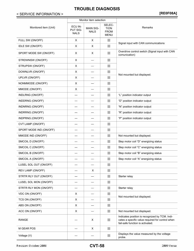
[RE0F08A]TROUBLE DIAGNOSIS
< SERVICE INFORMATION >
FULL SW (ON/OFF) X XSignal input with CAN communications
IDLE SW (ON/OFF) X X
SPORT MODE SW (ON/OFF) X X Overdrive control switch (Signal input with CAN comunication)
STRDWNSW (ON/OFF) X —
Not mounted but displayed.
STRUPSW (ON/OFF) X —
DOWNLVR (ON/OFF) X —
UPLVR (ON/OFF) X —
NONMMODE (ON/OFF) X —
MMODE (ON/OFF) X —
INDLRNG (ON/OFF) — — “L” position indicator output
INDDRNG (ON/OFF) — — “D” position indicator output
INDNRNG (ON/OFF) — — “N” position indicator output
INDRRNG (ON/OFF) — — “R” position indicator output
INDPRNG (ON/OFF) — — “P” position indicator output
CVT LAMP (ON/OFF) — —
SPORT MODE IND (ON/OFF) — —
MMODE IND (ON/OFF) — — Not mounted but displayed.
SMCOIL D (ON/OFF) — — Step motor coil “D” energizing status
SMCOIL C (ON/OFF) — — Step motor coil “C” energizing status
SMCOIL B (ON/OFF) — — Step motor coil “B” energizing status
SMCOIL A (ON/OFF) — — Step motor coil “A” energizing status
LUSEL SOL OUT (ON/OFF) — —
REV LAMP (ON/OFF) — X
STRTR RLY OUT (ON/OFF) — — Starter relay
LUSEL SOL MON (ON/OFF) — —
STRTR RLY MON (ON/OFF) — — Starter relay
VDC ON (ON/OFF) X —Not mounted but displayed.
TCS ON (ON/OFF) X —
ABS ON (ON/OFF) X —
ACC ON (ON/OFF) X — Not mounted but displayed.
RANGE — XIndicates position is recognized by TCM. Indi-cates a specific value required for control when fail-safe function is activated.
M GEAR POS — X
Voltage (V) — — Displays the value measured by the voltage probe.
Monitored item (Unit)
Monitor item selection
Remarks ECU IN-PUT SIG-
NALS
MAIN SIG-NALS
SELEC-TION FROM MENU
CVT-58

TROUBLE DIAGNOSIS[RE0F08A]
D
E
F
G
H
I
J
K
L
M
A
B
VT
N
O
P
< SERVICE INFORMATION >
C
Diagnosis Procedure without CONSULT-III INFOID:0000000004666893
OBD-II SELF-DIAGNOSTIC PROCEDURE (WITH GST)Refer to EC-612, "Generic Scan Tool (GST) Function".
Frequency (Hz) — —
The value measured by the pulse probe is dis-played.
DUTY-HI (high) (%) — —
DUTY-LOW (low) (%) — —
PLS WIDTH-HI (ms) — —
PLS WIDTH-LOW (ms) — —
Monitored item (Unit)
Monitor item selection
Remarks ECU IN-PUT SIG-
NALS
MAIN SIG-NALS
SELEC-TION FROM MENU
CVT-59

[RE0F08A]DTC U1000 CAN COMMUNICATION LINE
< SERVICE INFORMATION >DTC U1000 CAN COMMUNICATION LINEDescription INFOID:0000000004666894
CAN (Controller Area Network) is a serial communication line for real time application. It is an on-vehicle mul-tiplex communication line with high data communication speed and excellent malfunction detection ability.Many electronic control units are equipped onto a vehicle, and each control unit shares information and linkswith other control units during operation (not independent). In CAN communication, control units are con-nected with 2 communication lines (CAN-H line, CAN-L line) allowing a high rate of information transmissionwith less wiring. Each control unit transmits/receives data but selectively reads required data only.
On Board Diagnosis Logic INFOID:0000000004666895
• This is an OBD-II self-diagnostic item.• Diagnostic trouble code “U1000 CAN COMM CIRCUIT” with CONSULT-III is detected when TCM cannot
communicate to other control units.
Possible Cause INFOID:0000000004666896
Harness or connectors(CAN communication line is open or shorted.)
DTC Confirmation Procedure INFOID:0000000004666897
NOTE:If “DTC Confirmation Procedure” has been previously performed, always turn ignition switch OFF andwait at least 10 seconds before performing the next test.After the repair, touch “ERASE” on “SELF-DIAG RESULTS” and then perform the following procedure to con-firm the malfunction is eliminated.
WITH CONSULT-III1. Turn ignition switch ON. (Do not start engine.)2. Select “DATA MONITOR” mode for “TRANSMISSION” with CONSULT-III.3. Start engine and wait for at least 6 seconds.4. If DTC is detected, go to CVT-62, "Diagnosis Procedure" .
WITH GSTFollow the procedure “WITH CONSULT-III”.
CVT-60

DTC U1000 CAN COMMUNICATION LINE[RE0F08A]
D
E
F
G
H
I
J
K
L
M
A
B
VT
N
O
P
< SERVICE INFORMATION >
C
Wiring Diagram - CVT - CAN INFOID:0000000004666898
TCM TERMINALS AND REFERENCE VALUESRefer to CVT-49, "TCM Terminal and Reference Value".
BCWA0668E
CVT-61
[RE0F08A]DTC U1000 CAN COMMUNICATION LINE
< SERVICE INFORMATION >Diagnosis Procedure INFOID:0000000004666899
1.CHECK CAN COMMUNICATION CIRCUIT
With CONSULT-III1. Turn ignition switch ON and start engine.2. Select “SELF-DIAG RESULTS” mode for “TRANSMISSION” with CONSULT-III.Is any malfunction of the “U1000 CAN COMM CIRCUIT” indicated?YES >> Print out CONSULT-III screen, go to LAN section. Refer to LAN-26, "CAN System Specification
Chart" .NO >> INSPECTION END
CVT-62

DTC U1010 TRANSMISSION CONTROL MODULE (CAN)[RE0F08A]
D
E
F
G
H
I
J
K
L
M
A
B
VT
N
O
P
< SERVICE INFORMATION >
C
DTC U1010 TRANSMISSION CONTROL MODULE (CAN)Description INFOID:0000000004666900
CAN (Controller Area Network) is a serial communication line for real time application. It is an on-vehicle mul-tiplex communication line with high data communication speed and excellent malfunction detection ability.Many electronic control units are equipped onto a vehicle, and each control unit shares information and linkswith other control units during operation (not independent). In CAN communication, control units are con-nected with 2 communication lines (CAN-H line, CAN-L line) allowing a high rate of information transmissionwith less wiring. Each control unit transmits/receives data but selectively reads required data only.
On Board Diagnosis Logic INFOID:0000000004666901
• This is an OBD-II self-diagnostic item.• Diagnostic trouble code “U1010 CONTROL UNIT(CAN)” with CONSULT-III is detected when TCM cannot
communicate to other control units.
Possible Cause INFOID:0000000004666902
Harness or connectors(CAN communication line is open or shorted.)
DTC Confirmation Procedure INFOID:0000000004666903
NOTE:If “DTC Confirmation Procedure” has been previously performed, always turn ignition switch OFF andwait at least 10 seconds before performing the next test.After the repair, touch “ERASE” on “SELF-DIAG RESULTS” and then perform the following procedure to con-firm the malfunction is eliminated.
WITH CONSULT-III1. Turn ignition switch ON. (Do not start engine.)2. Select “DATA MONITOR” mode for “TRANSMISSION” with CONSULT-III.3. Start engine and wait for at least 6 seconds.4. If DTC is detected, go to CVT-63, "Diagnosis Procedure".
WITH GSTFollow the procedure “WITH CONSULT-III”.
Diagnosis Procedure INFOID:0000000004666904
1.CHECK DTC
With CONSULT-III1. Turn ignition switch ON. (Do not start engine.)2. Select “SELF-DIAG RESULTS” mode for “TRANSMISSION” with CONSULT-III.3. Touch “ERASE”.4. Turn ignition switch OFF and wait for at least 10 seconds.5. Perform “DTC confirmation procedure”. Refer to CVT-63, "DTC Confirmation Procedure".Is any malfunction of the “U1010 CONTROL UNIT(CAN)” indicated?YES >> Replace the TCM. Refer to CVT-170, "Removal and Installation".NO >> INSPECTION END
CVT-63

[RE0F08A]DTC P0615 START SIGNAL CIRCUIT
< SERVICE INFORMATION >DTC P0615 START SIGNAL CIRCUITDescription INFOID:0000000004666905
• TCM controls starter relay in IPDM E/R.• TCM switches starter relay ON at “P” or “N” position and allows to crank engine. • Then it prohibits cranking other than at “P” or “N” position.
CONSULT-III Reference Value in Data Monitor Mode INFOID:0000000004666906
On Board Diagnosis Logic INFOID:0000000004666907
• This is not an OBD-II self-diagnostic item. • Diagnostic trouble code “P0615 STARTER RELAY/CIRC” with CONSULT-III is detected when starter relay
switched ON other than at “P” or “N” position. (or when switched OFF at “P” or “N” position).
Possible Cause INFOID:0000000004666908
• Harness or connectors(Starter relay and TCM circuit is open or shorted.)
• Starter relay
DTC Confirmation Procedure INFOID:0000000004666909
CAUTION:Always drive vehicle at a safe speed.NOTE:If “DTC Confirmation Procedure” has been previously performed, always turn ignition switch OFF andwait at least 10 seconds before performing the next test.After the repair, touch “ERASE” on “SELF-DIAG RESULTS” and then perform the following procedure to con-firm the malfunction is eliminated.
WITH CONSULT-III1. Turn ignition switch ON. (Do not start engine.)2. Select “DATA MONITOR” mode for “TRANSMISSION” with CONSULT-III.3. Start engine.4. Drive vehicle for at least 2 consecutive seconds.5. If DTC is detected, go to CVT-66, "Diagnosis Procedure" .
Item name Condition Display value
STRTR RLY OUTSelector lever in “P” and “N” positions ON
Selector lever in other positions OFF
STRTR RLY MONSelector lever in “P” and “N” positions ON
Selector lever in other positions OFF
CVT-64
DTC P0615 START SIGNAL CIRCUIT[RE0F08A]
D
E
F
G
H
I
J
K
L
M
A
B
VT
N
O
P
< SERVICE INFORMATION >
C
Wiring Diagram - CVT - STSIG INFOID:0000000004666910
TCM TERMINALS AND REFERENCE VALUESRefer to CVT-49, "TCM Terminal and Reference Value" .
BCWA0669E
CVT-65

[RE0F08A]DTC P0615 START SIGNAL CIRCUIT
< SERVICE INFORMATION >Diagnosis Procedure INFOID:0000000004666911
1.CHECK STARTER RELAY SIGNAL
With CONSULT-III1. Turn ignition switch ON. (Do not start engine.)2. Select “SELECTION FROM MENU” in “DATA MONITOR” mode for “TRANSMISSION” with CONSULT-III
and check monitor “STRTR RLY OUT”, “STRTR RLY MON”(PNP relay) ON/OFF.
Without CONSULT-III1. Turn ignition switch ON. (Do not start engine.)2. Check voltage between the TCM connector terminal and
ground.
OK or NGOK >> GO TO 3.NG >> GO TO 2.
2.DETECT MALFUNCTIONING ITEM
Check the following:• Starter relay. Refer to PG-68 .• Open or short-circuit in the harness between TCM and the starter relay. Refer to CVT-65, "Wiring Diagram -
CVT - STSIG" .• Ground circuit for the starter relay. Refer to SC-11, "Wiring Diagram - START -" .OK or NGOK >> GO TO 3.NG >> Repair or replace damaged parts.
3.CHECK DTC
Perform CVT-64, "DTC Confirmation Procedure" .OK or NGOK >> INSPECTION ENDNG >> GO TO 4.
4.CHECK TCM
1. Check TCM input/output signals. Refer to CVT-49, "TCM Terminal and Reference Value" .2. If NG, re-check TCM pin terminals for damage or loose connection with harness connector.OK or NGOK >> INSPECTION ENDNG >> Repair or replace damaged parts.
Item name Condition Display value
STRTR RLY OUT
Selector lever in “P” and “N” positions ON
Selector lever in other po-sitions OFF
STRTR RLY MON
Selector lever in “P” and “N” positions ON
Selector lever in other po-sitions OFF
Terminal Item Condition Data (Approx.)
24 Starter relay
Selector lever in “N” and “P” positions Battery voltage
Selector lever in other posi-tions 0 V
SCIA2022E
CVT-66

DTC P0703 STOP LAMP SWITCH CIRCUIT[RE0F08A]
D
E
F
G
H
I
J
K
L
M
A
B
VT
N
O
P
< SERVICE INFORMATION >
C
DTC P0703 STOP LAMP SWITCH CIRCUITDescription INFOID:0000000004666912
ON, OFF status of the stop lamp switch is sent via the CAN communication from the combination meter toTCM using the signal.
CONSULT-III Reference Value in Data Monitor Mode INFOID:0000000004666913
On Board Diagnosis Logic INFOID:0000000004666914
• This is not an OBD-II self-diagnostic item. • Diagnostic trouble code “P0703 BRAKE SW/CIRC” with CONSULT-III is detected when the stop lamp switch
does not switch to ON and OFF.- The stop lamp switch does not switch to ON, OFF.
Possible Cause INFOID:0000000004666915
• Harness or connectors(Stop lamp switch, and combination meter circuit are open or shorted.)(CAN communication line is open or shorted.)
• Stop lamp switch
DTC Confirmation Procedure INFOID:0000000004666916
CAUTION:Always drive vehicle at a safe speed.NOTE:If “DTC Confirmation Procedure” has been previously performed, always turn ignition switch OFF andwait at least 10 seconds before performing the next test.After the repair, touch “ERASE” on “SELF-DIAG RESULTS” and then perform the following procedure to con-firm the malfunction is eliminated.
WITH CONSULT-III1. Turn ignition switch ON. (Do not start engine.)2. Select “DATA MONITOR” mode for “TRANSMISSION” with CONSULT-III.3. Start engine.4. Start vehicle for at least 3 consecutive seconds.5. If DTC is detected, go to CVT-67, "Diagnosis Procedure".
Diagnosis Procedure INFOID:0000000004666917
1.CHECK CAN COMMUNICATION LINE
Perform the self-diagnosis check. Refer to CVT-51, "CONSULT-III Function (TRANSMISSION)".Is any malfunction of the “U1000 CAN COMM CIRCUIT” indicated?YES >> Check CAN communication line. Refer to CVT-60.NO >> GO TO 2.
2.CHECK STOP LAMP SWITCH CIRCUIT
With CONSULT-III1. Turn ignition switch ON. (Do not start engine.)2. Select “ECU INPUT SIGNALS” in “DATA MONITOR” mode for “TRANSMISSION” with CONSULT-III.3. Read out ON/OFF switching action of the “BRAKE SW”.
Item name Condition Display value
BRAKE SWDepressed brake pedal ON
Released brake pedal OFF
CVT-67

[RE0F08A]DTC P0703 STOP LAMP SWITCH CIRCUIT
< SERVICE INFORMATION >
OK or NGOK >> INSPECTION ENDNG >> GO TO 3.
3.CHECK STOP LAMP SWITCH
Check continuity between stop lamp switch harness connector E13terminals 1 and 2. Refer to CVT-153, "Wiring Diagram - CVT - NON-DTC".
Check stop lamp switch after adjusting brake pedal — refer toBR-6.OK or NGOK >> Check the following. If NG, repair or replace damaged parts.
• Harness for short or open between battery and stop lamp switch.• Harness for short or open between stop lamp switch and combination meter.
NG >> Repair or replace the stop lamp switch.
Item name Condition Display value
BRAKE SWDepressed brake pedal ON
Released brake pedal OFF
Condition Continuity
When brake pedal is depressed Yes
When brake pedal is released No
SCIA7982E
CVT-68

DTC P0705 PARK/NEUTRAL POSITION SWITCH[RE0F08A]
D
E
F
G
H
I
J
K
L
M
A
B
VT
N
O
P
< SERVICE INFORMATION >
C
DTC P0705 PARK/NEUTRAL POSITION SWITCHDescription INFOID:0000000004666918
• The PNP switch is included in the control valve assembly.• The PNP switch includes 4 transmission position switches.• TCM judges the selector lever position by the PNP switch signal.
CONSULT-III Reference Value in Data Monitor Mode INFOID:0000000004666919
On Board Diagnosis Logic INFOID:0000000004666920
• This is an OBD-II self-diagnostic item.• Diagnostic trouble code “P0705 PNP SW/CIRC” with CONSULT-III is detected under the following condi-
tions.- When TCM does not receive the correct voltage signal from the PNP switches 1, 2, 3 and 4 based on the
gear position.- When the signal from monitor terminal of PNP switch 3 is different from PNP switch 3.
Possible Cause INFOID:0000000004666921
• Harness or connectors(PNP switches 1, 2, 3, 4 and TCM circuit is open or shorted.)
• PNP switches 1, 2, 3, 4 • PNP switch 3 monitor terminal is open or shorted
DTC Confirmation Procedure INFOID:0000000004666922
CAUTION:Always drive vehicle at a safe speed.NOTE:If “DTC Confirmation Procedure” has been previously performed, always turn ignition switch OFF andwait at least 10 seconds before performing the next test.After the repair, touch “ERASE” on “SELF-DIAG RESULTS” and then perform the following procedure to con-firm the malfunction is eliminated.
WITH CONSULT-III
Shift position PNP switch 1 PNP switch 2 PNP switch 3 PNP switch 4 PNP switch 3 (monitor)
P OFF OFF OFF OFF OFF
R ON OFF OFF ON OFF
N ON ON OFF OFF OFF
D ON ON ON ON ON
L OFF ON ON OFF ON
Item name Condition Display value
INH SW3MSelector lever in “D” and “L” positions ON
Selector lever in “P”, “R” and “N” positions OFF
INH SW4Selector lever in “R” and “D” positions ON
Selector lever in “P”, “N” and “L” positions OFF
INH SW3Selector lever in “D” and “L” positions ON
Selector lever in “P”, “R” and “N” positions OFF
INH SW2Selector lever in “N”, “D” and “L” positions ON
Selector lever in “P” and “R” positions OFF
INH SW1Selector lever in “R”, “N” and “D” positions ON
Selector lever in “P” and “L” positions OFF
CVT-69

[RE0F08A]DTC P0705 PARK/NEUTRAL POSITION SWITCH
< SERVICE INFORMATION >1. Turn ignition switch ON. (Do not start engine.)2. Select “DATA MONITOR” mode for “TRANSMISSION” with CONSULT-III.3. Start engine.4. Drive vehicle and maintain the following conditions for at least 2 consecutive seconds.
VEHICLE SPEED: More than 10 km/h (6 MPH)ENG SPEED: More than 450 rpmACC PEDAL OPEN: More than 1.0/8
5. If DTC is detected, go to CVT-72, "Diagnosis Procedure" .
WITH GSTFollow the procedure “WITH CONSULT-III”.
CVT-70

DTC P0705 PARK/NEUTRAL POSITION SWITCH[RE0F08A]
D
E
F
G
H
I
J
K
L
M
A
B
VT
N
O
P
< SERVICE INFORMATION >
C
Wiring Diagram - CVT - PNP/SW INFOID:0000000004666923
TCM TERMINALS AND REFERENCE VALUESRefer to CVT-49, "TCM Terminal and Reference Value" .
BCWA0670E
CVT-71

[RE0F08A]DTC P0705 PARK/NEUTRAL POSITION SWITCH
< SERVICE INFORMATION >Diagnosis Procedure INFOID:0000000004666924
1. CHECK PNP SW SIGNALS
With CONSULT-III1. Turn ignition switch ON. (Do not start engine.)2. Select “ECU INPUT SIGNALS” in “DATA MONITOR” mode for “TRANSMISSION” with CONSULT-III.3. Change selector lever to “P”, “R”, “N”, “D” and “L” positions to check the value of “INH SW1”“INH SW2”
“INH SW3”“INH SW4” and “INH SW3M”.
Without CONSULT-III1. Turn ignition switch ON. (Do not start engine.)2. Change selector lever to “P“, “R”, “N”, “D” and “L” positions to
check voltage between the TCM connector terminals andground.
OK or NGOK >> GO TO 5.NG >> GO TO 2.
2. CHECK PNP SWITCH CIRCUIT
1. Turn ignition switch OFF.2. Disconnect TCM connector.
Shift posi-tion
“INH SW1” “INH SW2” “INH SW3” “INH SW4” “INH SW3M”
P OFF OFF OFF OFF OFF
R ON OFF OFF ON OFF
N ON ON OFF OFF OFF
D ON ON ON ON ON
L OFF ON ON OFF ON
Shift po-sition
Connector E32
Terminal
27 - Ground 34 - Ground 35 - Ground 36 - Ground 32 - Ground
P Battery volt-age
10.0 V - Bat-tery voltage
8.0 V - Bat-tery voltage
10.0 V - Bat-tery voltage
8.0 V - Bat-tery volt-
age
R 0 V 10.0 V - Bat-tery voltage
8.0 V - Bat-tery voltage 0 V
8.0 V - Bat-tery volt-
age
N 0 V 0 V 8.0 V - Bat-tery voltage
10.0 V - Bat-tery voltage
8.0 V - Bat-tery volt-
age
D 0 V 0 V 0 V 0 V 0 V
L Battery volt-age 0 V 0 V 10.0 V - Bat-
tery voltage 0 V
SCIA2024E
CVT-72

DTC P0705 PARK/NEUTRAL POSITION SWITCH[RE0F08A]
D
E
F
G
H
I
J
K
L
M
A
B
VT
N
O
P
< SERVICE INFORMATION >
C
3. Check continuity between TCM connector terminals and ground.
4. If OK, check harness for short-circuit to ground or power supply. OK or NGOK >> GO TO 5.NG >> GO TO 3.
3. CHECK HARNESS BETWEEN TCM AND PNP SWITCH
1. Turn ignition switch OFF.2. Disconnect TCM connector and CVT unit harness connector.3. Check continuity between TCM connector terminals and CVT
unit harness connector terminals.
4. If OK, check harness for short to ground and short to power.5. Reinstall any part removed. OK or NG OK >> GO TO 4. NG >> Repair or replace damaged parts.
4. DETECT MALFUNCTIONING ITEM
Check PNP switch. Refer to CVT-74, "Component Inspection" . OK or NG OK >> GO TO 5. NG >> Repair or replace damaged parts.
5.CHECK DTC
Perform CVT-69, "DTC Confirmation Procedure" .
Connector Terminal Condition Continuity
E32
27 - groundSelect lever in “P” and “L” positions No
Select lever in other positions Yes
34 - groundSelect lever in “P” and “R” positions No
Select lever in other positions Yes
35 - groundSelect lever in “P”, “R” and “N” posi-tions No
Select lever in other positions Yes
36 - groundSelect lever in “P”,“N” and “L” positions No
Select lever in other positions Yes
32 - groundSelect lever in “P”, “R” and “N” posi-tions No
Select lever in other positions Yes
SCIA5258E
Item Connector Terminal Continuity
TCM E32 27 Yes
CVT unit harness connector F46 4
TCM E32 34 Yes
CVT unit harness connector F46 5
TCM E32 35 Yes
CVT unit harness connector F46 14
TCM E32 32 Yes
CVT unit harness connector F46 18
TCM E32 36 Yes
CVT unit harness connector F46 15
SCIA3182E
CVT-73

[RE0F08A]DTC P0705 PARK/NEUTRAL POSITION SWITCH
< SERVICE INFORMATION >OK or NGOK >> INSPECTION ENDNG >> GO TO 6.
6.CHECK TCM
1. Check TCM input/output signals. Refer to CVT-49, "TCM Terminal and Reference Value" .2. If NG, re-check TCM pin terminals for damage or loose connection with harness connector.OK or NGOK >> INSPECTION ENDNG >> 1. Repair or replace damaged parts.
2. Replace the transaxle assembly. Refer to CVT-182, "Removal and Installation" .
Component Inspection INFOID:0000000004666925
PNP SWITCH1. Change selector lever to various positions to check the continu-
ity between terminals on the PNP switch and ground.
2. If NG, check continuity with control cable disconnected. (Refer to step 1 above.)3. If OK, with the control cable disconnected, adjust the control cable. Refer to CVT-175, "Adjustment of CVT
Position" .4. If NG, even when the control cable is disconnected, replace the transaxle assembly. Refer to CVT-182,
"Removal and Installation" .
PNP SW Shift position Connector Terminal Continuity
SW 1“R”, “N”, “D”
F46
4 - Ground Yes
other positions No
SW 2“N”, “D”, “L”
5 - Ground Yes
other positions No
SW 3“D”, “L”
14 - Ground Yes
other positions No
SW 4“R”, “D”
15 - Ground Yes
other positions No
SW 3 Moni-tor
“D”, “L” 18 - Ground
Yes
other positions No
SCIA4678E
CVT-74

DTC P0710 CVT FLUID TEMPERATURE SENSOR CIRCUIT[RE0F08A]
D
E
F
G
H
I
J
K
L
M
A
B
VT
N
O
P
< SERVICE INFORMATION >
C
DTC P0710 CVT FLUID TEMPERATURE SENSOR CIRCUITDescription INFOID:0000000004666926
• The CVT fluid temperature sensor is included in the control valve assembly.• The CVT fluid temperature sensor detects the CVT fluid temperature and sends a signal to the TCM.
CONSULT-III Reference Value in Data Monitor Mode INFOID:0000000004666927
Remarks: Specification data are reference values.
On Board Diagnosis Logic INFOID:0000000004666928
• This is an OBD-II self-diagnostic item.• Diagnostic trouble code “P0710 ATF TEMP SEN/CIRC” with CONSULT-III is detected when TCM receives
an excessively low or high voltage from the sensor.
Possible Cause INFOID:0000000004666929
• Harness or connectors(Sensor circuit is open or shorted.)
• CVT fluid temperature sensor
DTC Confirmation Procedure INFOID:0000000004666930
CAUTION:Always drive vehicle at a safe speed.NOTE:If “DTC Confirmation Procedure” has been previously performed, always turn ignition switch OFF andwait at least 10 seconds before performing the next test.After the repair, touch “ERASE” on “SELF-DIAG RESULTS” and then perform the following procedure to con-firm the malfunction is eliminated.
WITH CONSULT-III1. Turn ignition switch ON. (Do not start engine.)2. Select “DATA MONITOR” mode for “TRANSMISSION” with CONSULT-III.3. Start engine and maintain the following conditions for at least 10 minutes (Total).
VEHICLE SPEED: 10 km/h (6 MPH) or moreENG SPEED: 450 rpm more thanACC PEDAL OPEN: More than 1.0/8RANGE: “D” position
4. If DTC is detected, go to CVT-77, "Diagnosis Procedure".
WITH GSTFollow the procedure “WITH CONSULT-III”.
Item name Condition Display value (Approx.)
ATF TEMP SEN When CVT fluid temperature is 20°C (68°F). 2.0 V
When CVT fluid temperature is 80°C (176°F). 1.0 V
CVT-75
[RE0F08A]DTC P0710 CVT FLUID TEMPERATURE SENSOR CIRCUIT
< SERVICE INFORMATION >Wiring Diagram - CVT - FTS INFOID:0000000004666931
TCM TERMINALS AND REFERENCE VALUESRefer to CVT-49, "TCM Terminal and Reference Value".
BCWA0671E
CVT-76

DTC P0710 CVT FLUID TEMPERATURE SENSOR CIRCUIT[RE0F08A]
D
E
F
G
H
I
J
K
L
M
A
B
VT
N
O
P
< SERVICE INFORMATION >
C
Diagnosis Procedure INFOID:0000000004666932
1. CHECK CVT FLUID TEMPERATURE SENSOR SIGNAL
With CONSULT-III1. Start engine.2. Select “ECU INPUT SIGNALS” in “DATA MONITOR” mode for “TRANSMISSION” with CONSULT-III.3. Read out the value of “ATF TEMP SEN”.
Without CONSULT-III1. Start engine.2. Check voltage between TCM connector terminals.
3. Turn ignition switch OFF.4. Disconnect TCM connector.5. Check if there is continuity between connector terminal and
ground.OK or NGOK >> GO TO 5.NG >> GO TO 2.
2. CHECK CVT FLUID TEMPERATURE SENSOR CIRCUIT
1. Turn ignition switch OFF.2. Disconnect the TCM connector.3. Check resistance between TCM connector terminals.
OK or NGOK >> GO TO 5.NG >> GO TO 3.
3. CHECK CVT FLUID TEMPERATURE SENSOR
1. Turn ignition switch OFF.2. Disconnect CVT unit harness connector.
Item name Condition Display value (Approx.)
ATF TEMP SEN
When CVT fluid temperature is 20°C (68°F). 2.0 V
When CVT fluid temperature is 80°C (176°F). 1.0 V
Name Connector Terminal Temperature °C (°F)
Voltage (Approx.)
CVT fluid tem-perature sen-sor
E32 47 - 4220 (68) 2.0 V
80 (176) 1.0 V
SCIA2027E
Name Connector Terminal Temperature °C (°F)
Resistance (Approx.)
CVT fluid tem-perature sensor E32 47 - 42
20 (68) 6.5 kΩ
80 (176) 0.9 kΩ
SCIA2510E
CVT-77

[RE0F08A]DTC P0710 CVT FLUID TEMPERATURE SENSOR CIRCUIT
< SERVICE INFORMATION >3. Check resistance between CVT unit harness connector termi-
nals.
4. Reinstall any part removed.OK or NGOK >> GO TO 4.NG >> Replace the transaxle assembly. Refer to CVT-182, "Removal and Installation".
4. CHECK HARNESS BETWEEN TCM AND CVT FLUID TEMPERATURE SENSOR
1. Turn ignition switch OFF.2. Disconnect the TCM connector and CVT unit harness connector.3. Check continuity between TCM connector terminals and CVT
unit harness connector terminals.
4. If OK, check harness for short to ground and short to power.5. Reinstall any part removed. OK or NG OK >> GO TO 5. NG >> Repair or replace damaged parts.
5.CHECK DTC
Perform CVT-75, "DTC Confirmation Procedure" .OK or NGOK >> INSPECTION ENDNG >> GO TO 6.
6.CHECK TCM
1. Check TCM input/output signals. Refer to CVT-49, "TCM Terminal and Reference Value" .2. If NG, re-check TCM pin terminals for damage or loose connection with harness connector.OK or NGOK >> INSPECTION ENDNG >> Repair or replace damaged parts.
Component Inspection INFOID:0000000004666933
CVT FLUID TEMPERATURE SENSOR1. Turn ignition switch OFF.2. Disconnect CVT unit harness connector.
Name Connector Terminal Tempera-ture °C (°F)
Resistance (Approx.)
CVT fluid temperature sensor
F46 17 - 1920 (68) 6.5 kΩ
80 (176) 0.9 kΩ
SCIA4679E
Item Connector Terminal Continuity
TCM E32 42Yes
CVT unit harness connector F46 19
TCM E32 47Yes
CVT unit harness connector F46 17
SCIA4680E
CVT-78

DTC P0710 CVT FLUID TEMPERATURE SENSOR CIRCUIT[RE0F08A]
D
E
F
G
H
I
J
K
L
M
A
B
VT
N
O
P
< SERVICE INFORMATION >
C
3. Check resistance between CVT unit harness connector termi-nals.
4. If NG, replace the transaxle assembly. Refer to CVT-182,"Removal and Installation" .
Name Connector Terminal Tempera-ture °C (°F)
Resistance (Approx.)
CVT fluid temperature sensor
F46 17 - 19 20 (68) 6.5 kΩ
80 (176) 0.9 kΩ
SCIA4679E
CVT-79
[RE0F08A]DTC P0715 INPUT SPEED SENSOR CIRCUIT (PRI SPEED SENSOR)
< SERVICE INFORMATION >DTC P0715 INPUT SPEED SENSOR CIRCUIT (PRI SPEED SENSOR)Description INFOID:0000000004666934
• The input speed sensor (primary speed sensor) is included in the control valve assembly.• The input speed sensor (primary speed sensor) detects the primary pulley revolution speed and sends a sig-
nal to the TCM.
CONSULT-III Reference Value in Data Monitor Mode INFOID:0000000004666935
Remarks: Specification data are reference values.
On Board Diagnosis Logic INFOID:0000000004666936
• This is an OBD-II self-diagnostic item.• Diagnostic trouble code “P0715 INPUT SPD SEN/CIRC” with CONSULT-III is detected when TCM does not
receive the proper signal from the sensor.
Possible Cause INFOID:0000000004666937
• Harness or connectors(Sensor circuit is open or shorted.)
• Input speed sensor (Primary speed sensor)
DTC Confirmation Procedure INFOID:0000000004666938
CAUTION:Always drive vehicle at a safe speed.NOTE:If “DTC Confirmation Procedure” has been previously performed, always turn ignition switch OFF andwait at least 10 seconds before performing the next test.After the repair, touch “ERASE” on “SELF-DIAG RESULTS” and then perform the following procedure to con-firm the malfunction is eliminated.
WITH CONSULT-III1. Turn ignition switch ON and select “DATA MONITOR” mode for “TRANSMISSION” with CONSULT-III.2. Start engine and maintain the following conditions for at least 5 consecutive seconds.
VEHICLE SPEED: 10 km/h (6 MPH) or moreACC PEDAL OPEN: More than 1.0/8RANGE: “D” positionENG SPEED: 450 rpm or moreDriving location: Driving the vehicle uphill (increased engine load) will help maintain the drivingconditions required for this test.
3. If DTC is detected, go to CVT-82, "Diagnosis Procedure" .
WITH GSTFollow the procedure “WITH CONSULT-III”.
Item name Condition Display value
ENG SPEED SIG Engine running Closely matches the tachometer reading.
PRI SPEED SEN During driving (lock-up ON) Approximately matches the engine speed.
CVT-80

DTC P0715 INPUT SPEED SENSOR CIRCUIT (PRI SPEED SENSOR)[RE0F08A]
D
E
F
G
H
I
J
K
L
M
A
B
VT
N
O
P
< SERVICE INFORMATION >
C
Wiring Diagram - CVT - PRSCVT INFOID:0000000004666939
TCM TERMINALS AND REFERENCE VALUESRefer to CVT-49, "TCM Terminal and Reference Value".
BCWA0672E
CVT-81

[RE0F08A]DTC P0715 INPUT SPEED SENSOR CIRCUIT (PRI SPEED SENSOR)
< SERVICE INFORMATION >Diagnosis Procedure INFOID:0000000004666940
1.CHECK INPUT SIGNALS
With CONSULT-III1. Start engine.2. Select “ECU INPUT SIGNALS” in “DATA MONITOR” mode for “TRANSMISSION” with CONSULT-III.3. Start vehicle and read out the value of “PRI SPEED SEN”.
OK or NGOK >> GO TO 6.NG >> GO TO 2.
2.CHECK INPUT SPEED SENSOR (PRIMARY SPEED SENSOR)
1. Start engine.2. Check voltage between TCM connector terminals.
3. Check the pulse with CONSULT-III or oscilloscope, when vehi-cle cruises.
OK or NGOK >> GO TO 6. NG - 1 >> Battery voltage is not supplied: GO TO 3. NG - 2 >> Battery voltage is supplied, but there is a malfunction in
the frequency: GO TO 4.3. CHECK HARNESS BETWEEN TCM AND CVT UNIT HARNESS CONNECTOR (SENSOR POWER ANDSENSOR GROUND)1. Turn ignition switch OFF.2. Disconnect TCM connector and primary speed sensor harness connector.
Item name Condition Display value
PRI SPEED SEN During driving (lock-up ON)
Approximately matches the engine speed.
Item Connector Terminal Data (Approx.)
TCM E32 46 - 42 5.0 V
Name Condition
Input speed sensor (Primary speed sensor)
When running at 20 km/h (12 MPH) in “L” position with the closed throttle position signal OFF, use the CONSULT-III pulse frequency measuring function.CAUTION:Connect the data link connector to the vehicle-side diag-nosis connector.
Item Connector Terminal Name Data (Ap-prox.)
TCM E32 38 Input speed sensor (Primary speed sensor) 1000 Hz
SCIA1915E
CVT-82

DTC P0715 INPUT SPEED SENSOR CIRCUIT (PRI SPEED SENSOR)[RE0F08A]
D
E
F
G
H
I
J
K
L
M
A
B
VT
N
O
P
< SERVICE INFORMATION >
C
3. Check continuity between TCM connector terminals and primaryspeed sensor harness connector terminals.
4. If OK, check harness for short to ground and short to power.5. Reinstall any part removed. OK or NG OK >> GO TO 6. NG >> Repair open circuit or short to ground or short to power in harness or connectors.
4. CHECK HARNESS BETWEEN TCM AND CVT UNIT HARNESS CONNECTOR [INPUT SPEED SENSOR(PRIMARY SPEED SENSOR)]1. Turn ignition switch OFF.2. Disconnect TCM connector and primary speed sensor harness connector.3. Check continuity between TCM connector terminal and primary
speed sensor harness connector terminal.
4. If OK, check harness for short to ground and short to power.5. Reinstall any part removed. OK or NG OK >> GO TO 5. NG >> Repair open circuit or short to ground or short to power
in harness or connectors.5. CHECK THE TCM SHORT
Replace same type TCM, perform self-diagnosis check. Erase self-diagnostic results and then drive the vehi-cle [10 km/h (6 MPH) or more], perform self-diagnosis check. Refer to CVT-80, "DTC Confirmation Proce-dure". Is the “P0715 INPUT SPD SEN/CIRC” detected again? YES >> Replace the transaxle assembly. Refer to CVT-182, "Removal and Installation". NO >> Replace TCM. Refer to CVT-12, "Service After Replacing TCM and Transaxle Assembly".
6.CHECK DTC
Perform CVT-80, "DTC Confirmation Procedure".OK or NGOK >> INSPECTION ENDNG >> GO TO 7.
7.CHECK TCM
1. Check TCM input/output signals. Refer to CVT-49, "TCM Terminal and Reference Value".2. If NG, re-check TCM pin terminals for damage or loose connection with harness connector.OK or NGOK >> INSPECTION ENDNG >> Repair or replace damaged parts.
Item Connector Terminal Continuity
TCM E32 42 Yes
CVT unit harness connector F46 19
TCM E32 46 Yes
CVT unit harness connector F46 20
SCIA4681E
Item Connector Terminal Continuity
TCM E32 38Yes
CVT unit harness connector F46 22
SCIA4682E
CVT-83

[RE0F08A]DTC P0720 VEHICLE SPEED SENSOR CVT (SECONDARY SPEED SENSOR)
< SERVICE INFORMATION >DTC P0720 VEHICLE SPEED SENSOR CVT (SECONDARY SPEED SEN-SOR)Description INFOID:0000000004666941
The vehicle speed sensor CVT [output speed sensor (secondary speed sensor)] detects the revolution of theCVT output shaft and emits a pulse signal. The pulse signal is sent to the TCM, which converts it into vehiclespeed.
CONSULT-III Reference Value in Data Monitor Mode INFOID:0000000004666942
Remarks: Specification data are reference values.
On Board Diagnosis Logic INFOID:0000000004666943
• This is an OBD-II self-diagnostic item.• Diagnostic trouble code “P0720 VEH SPD SEN/CIR AT” with CONSULT-III is detected TCM does not
receive the proper signal from the sensor.
Possible Cause INFOID:0000000004666944
• Harness or connectors(Sensor circuit is open or shorted.)
• Output speed sensor (Secondary speed sensor)
DTC Confirmation Procedure INFOID:0000000004666945
CAUTION:Always drive vehicle at a safe speed.NOTE:If “DTC Confirmation Procedure” has been previously performed, always turn ignition switch OFF andwait at least 10 seconds before performing the next test.After the repair, touch “ERASE” on “SELF-DIAG RESULTS” and then perform the following procedure to con-firm the malfunction is eliminated.
WITH CONSULT-III1. Turn ignition switch ON and select “DATA MONITOR” mode for “TRANSMISSION” with CONSULT-III.2. Start engine and maintain the following conditions for at least 12 consecutive seconds.
ACC PEDAL OPEN: More than 1.0/8RANGE: “D” positionDriving location: Driving the vehicle uphill (increased engine load) will help maintain the drivingconditions required for this test.
3. If DTC is detected, go to CVT-86, "Diagnosis Procedure" .
WITH GSTFollow the procedure “WITH CONSULT-III”.
Item name Condition Display value
VSP SENSOR During driving Approximately matches the speedometer reading.
CVT-84

DTC P0720 VEHICLE SPEED SENSOR CVT (SECONDARY SPEED SENSOR)[RE0F08A]
D
E
F
G
H
I
J
K
L
M
A
B
VT
N
O
P
< SERVICE INFORMATION >
C
Wiring Diagram - CVT - SESCVT INFOID:0000000004666946
TCM TERMINALS AND REFERENCE VALUESRefer to CVT-49, "TCM Terminal and Reference Value" .
BCWA0673E
CVT-85

[RE0F08A]DTC P0720 VEHICLE SPEED SENSOR CVT (SECONDARY SPEED SENSOR)
< SERVICE INFORMATION >Diagnosis Procedure INFOID:0000000004666947
1.CHECK INPUT SIGNAL
With CONSULT-III1. Start engine.2. Select “ECU INPUT SIGNALS” in “DATA MONITOR” mode for “TRANSMISSION” with CONSULT-III.3. Start vehicle and read out the value of “VSP SENSOR”.
OK or NGOK >> GO TO 8.NG >> GO TO 2.
2. CHECK SECONDARY SPEED SENSOR
With CONSULT-III1. Start engine.2. Check power supply to output speed sensor (secondary speed sensor) by voltage between TCM connec-
tor terminals 10, 19 and 42. Refer to CVT-40, "Circuit Diagram" .
3. If OK, check the pulse when vehicle cruises.
OK or NG OK >> GO TO 8. NG >> GO TO 3.
3. CHECK POWER AND SENSOR GROUND
1. Turn ignition switch OFF.2. Disconnect the output speed sensor (secondary speed sensor) harness connector.3. Turn ignition switch ON.
Item name Condition Display value
VSP SENSOR During driving Approximately matches the speedometer reading.
Item Connector Terminal Data (Approx.)
TCM E31, E3210 - 42
Battery voltage19 - 42
Name Condition
Output speed sen-sor (Secondary speed sensor)
When running at 20 km/h (12 MPH) in “D” position, use the CONSULT-III pulse frequency measuring function.CAUTION:Connect the data link connector to the vehicle-side diag-nosis connector.
Item Connector Terminal Name Data (Ap-prox.)
TCM E32 29 Output speed sensor (Sec-ondary speed sensor) 570 Hz
SCIA2344E
CVT-86

DTC P0720 VEHICLE SPEED SENSOR CVT (SECONDARY SPEED SENSOR)[RE0F08A]
D
E
F
G
H
I
J
K
L
M
A
B
VT
N
O
P
< SERVICE INFORMATION >
C
4. Check voltage between output speed sensor (secondary speedsensor) harness connector terminals.
5. Check voltage between output speed sensor (secondary speedsensor) harness connector terminal and ground.
6. If OK, check harness for short to ground and short to power.7. Reinstall any part removed. OK or NG OK >> GO TO 4. NG - 1 >> Battery voltage is not supplied between terminals 1 and 3, terminals 1 and ground.: GO TO 6. NG - 2 >> Battery voltage is not supplied between terminals 1 and 3 only.: GO TO 7.
4. CHECK HARNESS BETWEEN TCM AND OUTPUT SPEED SENSOR (SECONDARY SPEED SENSOR)
1. Turn ignition switch OFF.2. Disconnect TCM connector and output speed sensor (secondary speed sensor) harness connector.3. Check continuity between TCM connector terminal and output
speed sensor (secondary speed sensor) harness connector ter-minal.
4. If OK, check harness for short to ground and short to power.5. Reinstall any part removed. OK or NG OK >> GO TO 5. NG >> Repair open circuit or short to ground or short to power in harness or connectors.
5. CHECK THE TCM SHORT
Replace same type TCM, perform self-diagnosis check. Erase self-diagnostic results and them drive the vehi-cle [more than 40 km/h (25 MPH)], perform self-diagnosis check. Refer to CVT-84, "DTC Confirmation Proce-dure" . Is “P0720 VEH SPD SEN/CIR AT” detected again? YES >> Replace the transaxle assembly. Refer to CVT-182, "Removal and Installation". NO >> Replace TCM. Refer to CVT-12, "Service After Replacing TCM and Transaxle Assembly" .
6. CHECK HARNESS BETWEEN TCM AND OUTPUT SPEED SENSOR (SECONDARY SPEED SENSOR)(POWER)1. Turn ignition switch OFF.2. Disconnect TCM connector and output speed sensor (secondary speed sensor) harness connector.
Item Connector Terminal Data (Ap-prox.)
Output speed sensor (Sec-ondary speed sensor) F48 3 - 1 Battery volt-
age
SCIA2345E
Item Connector Terminal Data (Ap-prox.)
Output speed sensor (Sec-ondary speed sensor) F48 3 - ground Battery volt-
age
SCIA2346E
Item Connector Terminal Continuity
TCM E32 29YesOutput speed sensor (Sec-
ondary speed sensor) F48 2
SCIA1967E
CVT-87
[RE0F08A]DTC P0720 VEHICLE SPEED SENSOR CVT (SECONDARY SPEED SENSOR)
< SERVICE INFORMATION >3. Check continuity between TCM connector terminals and output
speed sensor (secondary speed sensor) harness connector ter-minal. Refer to CVT-40, "Circuit Diagram" .
4. If OK, check harness for short to ground and short to power.5. Reinstall any part removed. OK or NG OK >> 10 A fuse (No. 49, located in the IPDM E/R) or ignition switch are malfunctioning. NG >> Repair open circuit or short to ground or short to power in harness or connectors.
7. CHECK HARNESS BETWEEN TCM AND OUTPUT SPEED SENSOR (SECONDARY SPEED SENSOR)(SENSOR GROUND)1. Turn ignition switch OFF.2. Disconnect TCM connector and output speed sensor (secondary speed sensor) harness connector.3. Check continuity between TCM connector terminal and output
speed sensor (secondary speed sensor) harness connector ter-minal.
4. If OK, check harness for short to ground and short to power.5. Reinstall any part removed. OK or NG OK >> GO TO 8. NG >> Repair open circuit or short to ground or short to power in harness or connectors.
8.CHECK DTC
Perform CVT-84, "DTC Confirmation Procedure" .OK or NGOK >> INSPECTION ENDNG >> GO TO 9.
9.CHECK TCM
1. Check TCM input/output signals. Refer to CVT-49, "TCM Terminal and Reference Value" .2. If NG, re-check TCM pin terminals for damage or loose connection with harness connector.OK or NGOK >> INSPECTION ENDNG >> Repair or replace damaged parts.
Item Connector Terminal Continuity
TCM E31 10YesOutput speed sensor (Sec-
ondary speed sensor) F48 3
TCM E31 19YesOutput speed sensor (Sec-
ondary speed sensor) F48 3 SCIA2369E
Item Connector Terminal Continuity
TCM E32 42YesOutput speed sensor (Sec-
ondary speed sensor) F48 1
SCIA2347E
CVT-88
DTC P0725 ENGINE SPEED SIGNAL[RE0F08A]
D
E
F
G
H
I
J
K
L
M
A
B
VT
N
O
P
< SERVICE INFORMATION >
C
DTC P0725 ENGINE SPEED SIGNALDescription INFOID:0000000004666948
The engine speed signal is sent from the ECM to the TCM.
CONSULT-III Reference Value in Data Monitor Mode INFOID:0000000004666949
Remarks: Specification data are reference values.
On Board Diagnosis Logic INFOID:0000000004666950
• This is not an OBD-II self-diagnostic item.• Diagnostic trouble code “P0725 ENGINE SPEED SIG” with CONSULT-III is detected when TCM does not
receive the engine speed signal (input by CAN communication) from ECM.
Possible Cause INFOID:0000000004666951
Harness or connectors(The ECM to the TCM circuit is open or shorted.)
DTC Confirmation Procedure INFOID:0000000004666952
CAUTION:Always drive vehicle at a safe speed.NOTE:If “DTC Confirmation Procedure” has been previously performed, always turn ignition switch OFF andwait at least 10 seconds before performing the next test.After the repair, touch “ERASE” on “SELF-DIAG RESULTS” and then perform the following procedure to con-firm the malfunction is eliminated.
WITH CONSULT-III1. Turn ignition switch ON and select “DATA MONITOR” mode for “TRANSMISSION” with CONSULT-III.2. Start engine and maintain the following conditions for at least 10 consecutive seconds.
PRI SPEED SEN: More than 1000 rpm3. If DTC is detected, go to CVT-89, "Diagnosis Procedure".
Diagnosis Procedure INFOID:0000000004666953
1. CHECK DTC WITH ECM
With CONSULT-III1. Turn ignition switch ON. (Do not start engine.)2. Select “SELF-DIAG RESULTS” mode for “ENGINE” with CONSULT-III. Refer to EC-604, "CONSULT-III
Function (ENGINE)".OK or NGOK >> GO TO 2.NG >> Check the DTC detected item. Refer to EC-604, "CONSULT-III Function (ENGINE)".
2. CHECK DTC WITH TCM
With CONSULT-III1. Turn ignition switch ON. (Do not start engine.)2. Select “SELF-DIAG RESULTS” mode for “TRANSMISSION” with CONSULT-III. Refer to CVT-51, "CON-
SULT-III Function (TRANSMISSION)".OK or NGOK >> GO TO 3.NG >> Check the DTC detected item. Refer to CVT-51, "CONSULT-III Function (TRANSMISSION)".
Item name Condition Display value
ENG SPEED SIG Engine running Closely matches the tachometer reading.
ACC PEDAL OPEN Released accelerator pedal - Fully depressed accel-erator pedal 0.0/8 - 8.0/8
CVT-89

[RE0F08A]DTC P0725 ENGINE SPEED SIGNAL
< SERVICE INFORMATION >• If DTC of CAN communication line is detected, go to CVT-60.
3. CHECK INPUT SIGNALS
With CONSULT-III1. Start engine.2. Select “ECU INPUT SIGNALS” in “DATA MONITOR” mode for “TRANSMISSION” with CONSULT-III.3. While monitoring “ENG SPEED SIG”, check for engine speed change corresponding to “ACC PEDAL
OPEN”.
OK or NGOK >> GO TO 4.NG >> Check ignition signal circuit. Refer to EC-996, "Component Description".
4. CHECK DTC
Perform CVT-89, "DTC Confirmation Procedure". OK or NG OK >> INSPECTION END NG >> GO TO 5.
5. CHECK TCM
1. Check TCM input/output signals. Refer to CVT-49, "TCM Terminal and Reference Value".2. If NG, re-check TCM pin terminals for damage or loose connection with harness connector. OK or NG OK >> INSPECTION END NG >> Repair or replace damaged parts.
Item name Condition Display value
ENG SPEED SIG Engine running Closely matches the ta-chometer reading.
ACC PEDAL OPENReleased accelerator pedal - Fully depressed accelerator pedal
0.0/8 - 8.0/8
CVT-90
DTC P0730 BELT DAMAGE[RE0F08A]
D
E
F
G
H
I
J
K
L
M
A
B
VT
N
O
P
< SERVICE INFORMATION >
C
DTC P0730 BELT DAMAGEDescription INFOID:0000000004666954
TCM selects the gear ratio using the engine load (throttle position), the primary pulley revolution speed, andthe secondary pulley revolution speed as input signal. Then it changes the operating pressure of the primarypulley and the secondary pulley and changes the groove width of the pulley.
CONSULT-III Reference Value in Data Monitor Mode INFOID:0000000004666955
Remarks: Specification data are reference values.
On Board Diagnosis Logic INFOID:0000000004666956
• This is not an OBD-II self-diagnostic item. • TCM calculates the actual gear ratio with input speed sensor (primary speed sensor) and output speed sen-
sor (secondary speed sensor).• Diagnostic trouble code “P0730 BELT DAMG” with CONSULT-III is detected, when TCM receives an unex-
pected gear ratio signal.
Possible Cause INFOID:0000000004666957
Transaxle assembly
DTC Confirmation Procedure INFOID:0000000004666958
CAUTION:Always drive vehicle at a safe speed.NOTE:If “DTC Confirmation Procedure” has been previously performed, always turn ignition switch OFF andwait at least 10 seconds before performing the next test.After the repair, perform the following procedure to confirm the malfunction is eliminated.
WITH CONSULT-III1. Turn ignition switch ON and select “DATA MONITOR” mode for “TRANSMISSION” with CONSULT-III.2. Make sure that output voltage of CVT fluid temperature sensor is within the range below.
ATF TEMP SEN: 1.0 - 2.0 VIf out of range, drive the vehicle to decrease the voltage (warm up the fluid) or stop engine toincrease the voltage (cool down the fluid)
3. Select “DATA MONITOR” mode for “TRANSMISSION” with CONSULT-III.4. Start engine and maintain the following conditions for at least 30 consecutive seconds.
TEST START FROM 0 km/h (0 MPH)CONSTANT ACCELERATION: Keep 30 sec or moreVEHICLE SPEED: 10 km/h (6 MPH) or moreACC PEDAL OPEN: More than 1.0/8RANGE: “D” positionENG SPEED: 450 rpm or more
5. If DTC is detected, go to CVT-91, "Diagnosis Procedure".
Diagnosis Procedure INFOID:0000000004666959
1.CHECK DTC
Perform CVT-91, "DTC Confirmation Procedure".Are any DTC displayed?YES - 1>> DTC except for “P0730 BELT DAMG” is displayed: Go to Check the DTC detected item. Refer to
CVT-51, "CONSULT-III Function (TRANSMISSION)".YES - 2>> DTC for “P0730 BELT DAMG” is displayed: Replace the transaxle assembly. Refer to CVT-182,
"Removal and Installation". NO >> INSPECTION END
Item name Condition Display value (Approx.)
GEAR RATIO During driving 2.56 - 0.43
CVT-91
[RE0F08A]DTC P0740 TORQUE CONVERTER CLUTCH SOLENOID VALVE
< SERVICE INFORMATION >DTC P0740 TORQUE CONVERTER CLUTCH SOLENOID VALVEDescription INFOID:0000000004666960
• The torque converter clutch solenoid valve is included in the control valve assembly.• The torque converter clutch solenoid valve is activated by the TCM in response to signals sent from the vehi-
cle speed and accelerator pedal position sensors. Lock-up piston operation will then be controlled.• Lock-up operation, however, is prohibited when CVT fluid temperature is too low.• When the accelerator pedal is depressed (less than 2.0/8) in lock-up condition, the engine speed should not
change abruptly. If there is a big jump in engine speed, there is no lock-up.
CONSULT-III Reference Value in Data Monitor Mode INFOID:0000000004666961
Remarks: Specification data are reference values.
On Board Diagnosis Logic INFOID:0000000004666962
• This is an OBD-II self-diagnostic item.• Diagnostic trouble code “P0740 TCC SOLENOID/CIRC” with CONSULT-III is detected under the following
conditions.- TCM detects an improper voltage drop when it tries to operate the solenoid valve.
Possible Cause INFOID:0000000004666963
• Torque converter clutch solenoid valve• Harness or connectors
(Solenoid circuit is open or shorted.)
DTC Confirmation Procedure INFOID:0000000004666964
NOTE:If “DTC Confirmation Procedure” has been previously performed, always turn ignition switch OFF andwait at least 10 seconds before performing the next test.After the repair, touch “ERASE” on “SELF-DIAG RESULTS” and then perform the following procedure to con-firm the malfunction is eliminated.
WITH CONSULT-III1. Turn ignition switch ON. (Do not start engine.)2. Select “DATA MONITOR” mode for “TRANSMISSION” with CONSULT-III and wait at least 10 consecutive
seconds.3. If DTC is detected, go to CVT-94, "Diagnosis Procedure" .
WITH GSTFollow the procedure “WITH CONSULT-III”.
Item name Condition Display value (Approx.)
ISOLT1Lock-up OFF 0.0 A
Lock-up ON 0.7 A
CVT-92

DTC P0740 TORQUE CONVERTER CLUTCH SOLENOID VALVE[RE0F08A]
D
E
F
G
H
I
J
K
L
M
A
B
VT
N
O
P
< SERVICE INFORMATION >
C
Wiring Diagram - CVT - TCV INFOID:0000000004666965
TCM TERMINALS AND REFERENCE VALUESRefer to CVT-49, "TCM Terminal and Reference Value" .
BCWA0674E
CVT-93

[RE0F08A]DTC P0740 TORQUE CONVERTER CLUTCH SOLENOID VALVE
< SERVICE INFORMATION >Diagnosis Procedure INFOID:0000000004666966
1.CHECK INPUT SIGNAL
With CONSULT-III1. Start engine.2. Select “MAIN SIGNALS” in “DATA MONITOR” mode for “TRANSMISSION” with CONSULT-III.3. Start vehicle and read out the value of “ISOLT1”.
Without CONSULT-III1. Start engine.2. Check voltage between TCM connector terminal and ground.
3. Turn ignition switch OFF.4. Disconnect TCM connector.5. Check if there is continuity between the connector terminal and
ground.OK or NGOK >> GO TO 5.NG >> GO TO 2.
2. CHECK TORQUE CONVERTER CLUTCH SOLENOID VALVE CIRCUIT
1. Turn ignition switch OFF.2. Disconnect TCM connector.3. Check resistance between TCM connector terminal and ground.
OK or NG OK >> GO TO 5. NG >> GO TO 3.
3. CHECK HARNESS BETWEEN TCM AND TORQUE CONVERTER CLUTCH SOLENOID VALVE
1. Turn ignition switch OFF.2. Disconnect TCM connector and CVT unit harness connector.
Item name Condition Display value (Approx.)
ISOLT1Lock-up OFF 0.0 A
Lock-up ON 0.7 A
Name Connector Terminal Condition Voltage (Approx.)
Torque con-verter clutch sole-noid valve
E31 3 - ground
When vehi-cle cruises in “D” posi-tion
Lock-up ON 6.0 V
Lock-up OFF 1.0 V
SCIA7954E
Solenoid valve Connector Terminal Resistance (Approx.)
Torque converter clutch so-lenoid valve E31 3 - Ground 3 - 9 Ω
SCIA1970E
CVT-94

DTC P0740 TORQUE CONVERTER CLUTCH SOLENOID VALVE[RE0F08A]
D
E
F
G
H
I
J
K
L
M
A
B
VT
N
O
P
< SERVICE INFORMATION >
C
3. Check continuity between TCM connector terminal and CVT unitharness connector terminal.
4. If OK, check harness for short to ground and short to power.5. If OK, check continuity between ground and CVT assembly.6. Reinstall any part removed. OK or NG OK >> GO TO 4. NG >> Repair or replace damaged parts.
4.CHECK VALVE RESISTANCE
1. Turn ignition switch OFF.2. Disconnect CVT unit harness connector.3. Check resistance between CVT unit harness connector terminal
and ground.
OK or NGOK >> GO TO 5.NG >> Repair or replace damaged parts.
5.CHECK DTC
Perform CVT-92, "DTC Confirmation Procedure" .OK or NGOK >> INSPECTION ENDNG >> GO TO 6.
6.CHECK TCM
1. Check TCM input/output signals. Refer to CVT-49, "TCM Terminal and Reference Value" .2. If NG, re-check TCM pin terminals for damage or loose connection with harness connector.OK or NGOK >> INSPECTION ENDNG >> Repair or replace damaged parts.
Component Inspection INFOID:0000000004666967
TORQUE CONVERTER CLUTCH SOLENOID VALVE1. Turn ignition switch OFF.2. Disconnect CVT unit harness connector.
Item Connector Terminal Continuity
TCM E31 3YesCVT unit harness connec-
tor F46 12
SCIA4683E
Solenoid Valve Connector Terminal Resistance (Ap-prox.)
Torque converter clutch sole-noid valve F46 12 - Ground 3 - 9 Ω
SCIA4684E
CVT-95

[RE0F08A]DTC P0740 TORQUE CONVERTER CLUTCH SOLENOID VALVE
< SERVICE INFORMATION >3. Check resistance between CVT unit harness connector terminal
and ground.
4. If NG, replace the transaxle assembly. Refer to CVT-182,"Removal and Installation" .
Solenoid Valve Connector Terminal Resistance (Ap-prox.)
Torque converter clutch sole-noid valve F46 12 - Ground 3 - 9 Ω
SCIA4684E
CVT-96

DTC P0744 A/T TCC S/V FUNCTION (LOCK-UP)[RE0F08A]
D
E
F
G
H
I
J
K
L
M
A
B
VT
N
O
P
< SERVICE INFORMATION >
C
DTC P0744 A/T TCC S/V FUNCTION (LOCK-UP)Description INFOID:0000000004666968
• The torque converter clutch solenoid valve is included in the control valve assembly.• This malfunction is detected when the torque converter clutch does not lock-up as instructed by the TCM.
This is not only caused by electrical malfunction (circuits open or shorted), but also by mechanical malfunc-tion such as control valve sticking, improper solenoid valve operation, etc.
CONSULT-III Reference Value in Data Monitor Mode INFOID:0000000004666969
Remarks: Specification data are reference values.
On Board Diagnosis Logic INFOID:0000000004666970
• This is an OBD-II self-diagnostic item.• Diagnostic trouble code “P0744 A/T TCC S/V FNCTN” with CONSULT-III is detected under the following
conditions.- When CVT cannot perform lock-up even if electrical circuit is good.- When TCM compares difference value with slip revolution and detects an irregularity.
Possible Cause INFOID:0000000004666971
• Torque converter clutch solenoid valve• Hydraulic control circuit
DTC Confirmation Procedure INFOID:0000000004666972
CAUTION:Always drive vehicle at a safe speed.NOTE:If “DTC Confirmation Procedure” has been previously performed, always turn ignition switch OFF andwait at least 10 seconds before performing the next test.After the repair, touch “ERASE” on “SELF-DIAG RESULTS” and then perform the following procedure to con-firm the malfunction is eliminated.
WITH CONSULT-III1. Turn ignition switch ON. (Do not start engine.)2. Select “DATA MONITOR” mode for “TRANSMISSION” with CONSULT-III.3. Start engine and maintain the following condition for at least 30 seconds.
ACC PEDAL OPEN: More than 1.0/8RANGE: “D” position [Vehicle speed: Constant speed of more than 40 km/h (25 MPH)]
4. If DTC is detected go to CVT-97, "Diagnosis Procedure".
WITH GSTFollow the procedure “WITH CONSULT-III”.
Diagnosis Procedure INFOID:0000000004666973
1.CHECK INPUT SIGNALS
With CONSULT-III1. Start engine.2. Select “ECU INPUT SIGNALS” in “DATA MONITOR” mode for “TRANSMISSION” with CONSULT-III.3. Start vehicle.4. Check if there is a great difference between “ENG SPEED SIG” and “PRI SPEED SEN”. (Lock-up ON.)
Item name Condition Display value
ENG SPEED SIG Engine running Closely matches the tachometer reading.
PRI SPEED SEN During driving (lock-up ON) Approximately matches the engine speed.
CVT-97

[RE0F08A]DTC P0744 A/T TCC S/V FUNCTION (LOCK-UP)
< SERVICE INFORMATION >
OK or NGOK >> GO TO 5.NG >> GO TO 2.
2.CHECK LINE PRESSURE
Perform line pressure test. Refer to CVT-40, "Inspections before Trouble Diagnosis".OK or NGOK >> GO TO 3.NG >> Repair or replace damaged parts. Refer to CVT-40, "Inspections before Trouble Diagnosis".
3.DETECT MALFUNCTIONING ITEM
Check the following:• Torque converter clutch solenoid valve. Refer to CVT-95, "Component Inspection".• Lock-up select solenoid valve. Refer to CVT-139, "Component Inspection".OK or NGOK >> GO TO 4.NG >> Repair or replace damaged parts.
4.CHECK OUTPUT SPEED SENSOR (SECONDARY SPEED SENSOR) SYSTEM AND INPUT SPEEDSENSOR (PRIMARY SPEED SENSOR) SYSTEMCheck output speed sensor (secondary speed sensor) system and input speed sensor (primary speed sensor)system. Refer to CVT-84, CVT-80.OK or NGOK >> GO TO 5.NG >> Repair or replace damaged parts.
5.CHECK DTC
Perform CVT-97, "DTC Confirmation Procedure".OK or NGOK >> INSPECTION ENDNG >> GO TO 6.
6.CHECK TCM
1. Check TCM input/output signals. Refer to CVT-49, "TCM Terminal and Reference Value".2. If NG, re-check TCM pin terminals for damage or loose connection with harness connector.OK or NGOK >> INSPECTION ENDNG >> 1. Repair or replace damaged parts.
2. Replace the transaxle assembly. Refer to CVT-182, "Removal and Installation".
Item name Condition Display value
ENG SPEED SIG Engine running Closely matches the ta-chometer reading.
PRI SPEED SEN During driving (lock-up ON) Approximately matches the engine speed.
CVT-98

DTC P0745 LINE PRESSURE SOLENOID VALVE[RE0F08A]
D
E
F
G
H
I
J
K
L
M
A
B
VT
N
O
P
< SERVICE INFORMATION >
C
DTC P0745 LINE PRESSURE SOLENOID VALVEDescription INFOID:0000000004666974
• The pressure control solenoid valve A (line pressure solenoid valve) is included in the control valve assem-bly.
• The pressure control solenoid valve A (line pressure solenoid valve) regulates the oil pump discharge pres-sure to suit the driving condition in response to a signal sent from the TCM.
CONSULT-III Reference Value in Data Monitor Mode INFOID:0000000004666975
Remarks: Specification data are reference values.
On Board Diagnosis Logic INFOID:0000000004666976
• This is an OBD-II self-diagnostic item.• Diagnostic trouble code “P0745 L/PRESS SOL/CIRC” with CONSULT-III is detected under the following
conditions.- TCM detects an improper voltage drop when it tries to operate the solenoid valve.- When TCM compares target value with monitor value and detects an irregularity.
Possible Cause INFOID:0000000004666977
• Harness or connectors(Solenoid circuit is open or shorted.)
• Pressure control solenoid valve A (Line pressure solenoid valve)
DTC Confirmation Procedure INFOID:0000000004666978
NOTE:If “DTC Confirmation Procedure” has been previously performed, always turn ignition switch OFF andwait at least 10 seconds before performing the next test.After the repair, perform the following procedure to confirm the malfunction is eliminated.
WITH CONSULT-III1. Turn ignition switch ON and select “DATA MONITOR” mode for “TRANSMISSION” with CONSULT-III.2. Start engine and wait at least 5 seconds.3. If DTC is detected, go to CVT-101, "Diagnosis Procedure".
WITH GSTFollow the procedure “WITH CONSULT-III”.
Item name Condition Display value (Approx.)
ISOLT2Release your foot from the accelerator pedal. 0.8 A
Press the accelerator pedal all the way down. 0.0 A
CVT-99

[RE0F08A]DTC P0745 LINE PRESSURE SOLENOID VALVE
< SERVICE INFORMATION >Wiring Diagram - CVT - LPSV INFOID:0000000004666979
TCM TERMINALS AND REFERENCE VALUESRefer to CVT-49, "TCM Terminal and Reference Value".
BCWA0675E
CVT-100

DTC P0745 LINE PRESSURE SOLENOID VALVE[RE0F08A]
D
E
F
G
H
I
J
K
L
M
A
B
VT
N
O
P
< SERVICE INFORMATION >
C
Diagnosis Procedure INFOID:0000000004666980
1. CHECK INPUT SIGNAL
With CONSULT-III1. Start engine.2. Select “MAIN SIGNALS” in “DATA MONITOR” mode for “TRANSMISSION” with CONSULT-III.3. Read out the value of “ISOLT2”.
Without CONSULT-III1. Start engine.2. Check voltage between TCM connector terminal and ground.
3. Turn ignition switch OFF.4. Disconnect TCM connector.5. Check if there is continuity between connector terminal and ground. OK or NG OK >> GO TO 5. NG >> GO TO 2.
2.CHECK PRESSURE CONTROL SOLENOID VALVE A (LINE PRESSURE SOLENOID VALVE) CIRCUIT
1. Turn ignition switch OFF.2. Disconnect TCM connector.3. Check resistance between TCM connector terminal and ground.
OK or NGOK >> GO TO 5.NG >> GO TO 3.
3.CHECK VALVE RESISTANCE
1. Turn ignition switch OFF.2. Disconnect CVT unit harness connector.
Item name Condition Display value (Approx.)
ISOLT2
Release your foot from the accelerator pedal. 0.8 A
Press the accelerator ped-al all the way down. 0.0 A
Name Connector Terminal Condition Voltage (Approx.)
Pressure control so-lenoid valve A (Line pres-sure sole-noid valve)
E31 1 - ground
Release your foot from the accelerator pedal. 5.0 - 7.0 V
Press the accelerator pedal all the way down. 1.0 - 3.0 V
SCIA2348E
Solenoid valve Connector Terminal Resistance (Ap-prox.)
Pressure control solenoid valve A (Line pressure solenoid valve) E31 1 - ground 3 - 9 Ω
SCIA4685E
CVT-101

[RE0F08A]DTC P0745 LINE PRESSURE SOLENOID VALVE
< SERVICE INFORMATION >3. Check resistance between CVT unit harness connector terminal
and ground.
OK or NGOK >> GO TO 4.NG >> Replace the transaxle assembly. Refer to CVT-182,
"Removal and Installation".4. CHECK HARNESS BETWEEN TCM AND PRESSURE CONTROL SOLENOID VALVE A (LINE PRES-SURE SOLENOID VALVE)1. Turn ignition switch OFF.2. Disconnect CVT unit harness connector and TCM connector.3. Check continuity between TCM connector terminal and CVT unit
harness connector terminal.
4. If OK, check harness for short to ground and short to power.5. If OK, check continuity between ground and CVT assembly.6. Reinstall any part removed.OK or NGOK >> GO TO 5.NG >> Repair open circuit or short to ground or short to power in harness or connectors.
5.CHECK DTC
Perform CVT-99, "DTC Confirmation Procedure".OK or NGOK >> INSPECTION ENDNG >> GO TO 6.
6.CHECK TCM
1. Check TCM terminals and reference values. Refer to CVT-49, "TCM Terminal and Reference Value".2. If NG, re-check TCM pin terminals for damage or loose connection with harness connector.OK or NGOK >> INSPECTION ENDNG >> 1. Repair or replace damaged parts.
2. Replace the transaxle assembly. Refer to CVT-182, "Removal and Installation".
Component Inspection INFOID:0000000004666981
PRESSURE CONTROL SOLENOID VALVE A (LINE PRESSURE SOLENOID VALVE)1. Turn ignition switch OFF.2. Disconnect CVT unit harness connector.
Solenoid valve Connector Terminal Resistance (Ap-prox.)
Pressure control solenoid valve A (Line pressure solenoid valve) F46 2 - Ground 3 - 9 Ω
SCIA4686E
Item Connector Terminal Continuity
TCM E31 1Yes
CVT unit harness connector F46 2
SCIA4687E
CVT-102

DTC P0745 LINE PRESSURE SOLENOID VALVE[RE0F08A]
D
E
F
G
H
I
J
K
L
M
A
B
VT
N
O
P
< SERVICE INFORMATION >
C
3. Check resistance between CVT unit harness connector terminaland ground.
4. If NG, replace the transaxle assembly. Refer to CVT-182,"Removal and Installation".
Solenoid valve Connector Terminal Resistance (Ap-prox.)
Pressure control solenoid valve A (Line pressure solenoid valve) F46 2 - Ground 3 - 9 Ω
SCIA4686E
CVT-103

[RE0F08A]
DTC P0746 PRESSURE CONTROL SOLENOID A PERFORMANCE (LINE PRES-SURE SOLENOID VALVE)
< SERVICE INFORMATION >DTC P0746 PRESSURE CONTROL SOLENOID A PERFORMANCE (LINEPRESSURE SOLENOID VALVE)Description INFOID:0000000004666982
• The pressure control solenoid valve A (line pressure solenoid valve) is included in the control valve assem-bly.
• The pressure control solenoid valve A (line pressure solenoid valve) regulates the oil pump discharge pres-sure to suit the driving condition in response to a signal sent from the TCM.
CONSULT-III Reference Value in Data Monitor Mode INFOID:0000000004666983
Remarks: Specification data are reference values.
On Board Diagnosis Logic INFOID:0000000004666984
• This is an OBD-II self-diagnostic item.• Diagnostic trouble code “P0746 PRS CNT SOL/A FCTN” with CONSULT-III is detected under the following
conditions.- Unexpected gear ratio was detected in the LOW side due to excessively low line pressure.
Possible Cause INFOID:0000000004666985
• Line pressure control system• Output speed sensor (Secondary speed sensor)• Input speed sensor (Primary speed sensor)
DTC Confirmation Procedure INFOID:0000000004666986
CAUTION:Always drive vehicle at a safe speed.NOTE:If “DTC Confirmation Procedure” has been previously performed, always turn ignition switch OFF andwait at least 10 seconds before performing the next test.After the repair, touch “ERASE” on “SELF-DIAG RESULTS” and then perform the following procedure to con-firm the malfunction is eliminated.
WITH CONSULT-III1. Turn ignition switch ON and select “DATA MONITOR” mode for “TRANSMISSION” with CONSULT-III.2. Start engine and maintain the following conditions for at least 10 consecutive seconds. Test start from 0
km/h (0 MPH).ATF TEMP SEN: 1.0 - 2.0 VACC PEDAL OPEN: More than 1.0/8RANGE: “D” positionVEHICLE SPEED: 10 km/h (6 MPH) More thanDriving location: Driving the vehicle uphill (increased engine load) will help maintain the drivingconditions required for this test.
3. If DTC is detected, go to CVT-104, "Diagnosis Procedure".
WITH GSTFollow the procedure “WITH CONSULT-III”.
Diagnosis Procedure INFOID:0000000004666987
1. CHECK INPUT SIGNAL
With CONSULT-III1. Start engine.2. Select “MAIN SIGNALS” in “DATA MONITOR” mode for “TRANSMISSION” with CONSULT-III.3. Start vehicle and read out the value of “PRI PRESS”.
Item name Condition Display value (Approx.)
PRI PRESS “N” position idle 0.4 MPa
CVT-104

DTC P0746 PRESSURE CONTROL SOLENOID A PERFORMANCE (LINE PRES-SURE SOLENOID VALVE)
[RE0F08A]
D
E
F
G
H
I
J
K
L
M
A
B
VT
N
O
P
< SERVICE INFORMATION >
C
Without CONSULT-III1. Start engine.2. Check voltage between TCM connector terminal and ground.
OK or NG OK >> GO TO 5. NG >> GO TO 2.
2.CHECK LINE PRESSURE
Perform line pressure test. Refer to CVT-40, "Inspections before Trouble Diagnosis".OK or NGOK >> GO TO 3.NG >> Repair or replace damaged parts. Refer to CVT-40, "Inspections before Trouble Diagnosis".
3.DETECT MALFUNCTIONING ITEM
Check pressure control solenoid valve A (line pressure solenoid valve). Refer to CVT-102, "ComponentInspection".OK or NGOK >> GO TO 4.NG >> Repair or replace damaged parts.
4.CHECK OUTPUT SPEED SENSOR (SECONDARY SPEED SENSOR) SYSTEM AND INPUT SPEEDSENSOR (PRIMARY SPEED SENSOR) SYSTEMCheck output speed sensor (secondary speed sensor) system and input speed sensor (primary speed sensor)system. Refer to CVT-84, CVT-80.OK or NGOK >> GO TO 5.NG >> Repair or replace damaged parts.
5.DETECT MALFUNCTIONING ITEM
Check the following:• Power supply and ground circuit for TCM. Refer to CVT-126, "Wiring Diagram - CVT - POWER".• The TCM pin terminals for damage or loose connection with harness connector.OK or NGOK >> GO TO 6.NG >> Repair or replace damaged parts.
6.CHECK DTC
Perform CVT-104, "DTC Confirmation Procedure".OK or NGOK >> INSPECTION ENDNG >> Replace the transaxle assembly or TCM. Refer to CVT-182, "Removal and Installation".
Item name Condition Display value (Approx.)
PRI PRESS “N” position idle. 0.8 A
Name Connector Terminal Condition Voltage (Approx.)
Transmission fluid pressure sensor B (Pri-mary pres-sure sensor)
E32 41 - ground “N” position idle. 0.7 V
SCIA1922E
CVT-105

[RE0F08A]
DTC P0776 PRESSURE CONTROL SOLENOID B PERFORMANCE (SEC PRES-SURE SOLENOID VALVE)
< SERVICE INFORMATION >DTC P0776 PRESSURE CONTROL SOLENOID B PERFORMANCE (SECPRESSURE SOLENOID VALVE)Description INFOID:0000000004666988
• The pressure control solenoid valve B (secondary pressure solenoid valve) is included in the control valveassembly.
• The pressure control solenoid valve B (secondary pressure solenoid valve) regulates the secondary pres-sure to suit the driving condition in response to a signal sent from the TCM.
CONSULT-III Reference Value in Data Monitor Mode INFOID:0000000004666989
Remarks: Specification data are reference values.
On Board Diagnosis Logic INFOID:0000000004666990
• This is an OBD-II self-diagnostic item. • Diagnostic trouble code “P0776 PRS CNT SOL/B FCTN” with CONSULT-III is detected when secondary
pressure is too high or too low compared with the commanded value while driving.
Possible Cause INFOID:0000000004666991
• Harness or connectors(Solenoid circuit is open or shorted.)
• Pressure control solenoid valve B (Secondary pressure solenoid valve system)• Transmission fluid pressure sensor A (Secondary pressure sensor)• Line pressure control system
DTC Confirmation Procedure INFOID:0000000004666992
CAUTION:Always drive vehicle at a safe speed.NOTE:If “DTC Confirmation Procedure” has been previously performed, always turn ignition switch OFF andwait at least 10 seconds before performing the next test.After the repair, perform the following procedure to confirm the malfunction is eliminated.
WITH CONSULT-III1. Turn ignition switch ON and select “DATA MONITOR” mode for “TRANSMISSION” with CONSULT-III.2. Start engine and maintain the following conditions for at least 30 consecutive seconds.
ATF TEMP SEN: 1.0 - 2.0 VACC PEDAL OPEN: More than 1.0/8RANGE: “D” positionVEHICLE SPEED: 10 km/h (6 MPH) More thanDriving location: Driving the vehicle uphill (increased engine load) will help maintain the drivingconditions required for this test.
3. If DTC is detected, go to CVT-106, "Diagnosis Procedure".
WITH GSTFollow the procedure “WITH CONSULT-III”.
Diagnosis Procedure INFOID:0000000004666993
1.CHECK INPUT SIGNAL
With CONSULT-III1. Start engine.2. Select “MAIN SIGNALS” in “DATA MONITOR” mode for “TRANSMISSION” with CONSULT-III.3. Start vehicle and read out the value of “SEC PRESS”.
Item name Condition Display value (Approx.)
SEC PRESS “N” position idle 0.8 MPa
CVT-106

DTC P0776 PRESSURE CONTROL SOLENOID B PERFORMANCE (SEC PRES-SURE SOLENOID VALVE)
[RE0F08A]
D
E
F
G
H
I
J
K
L
M
A
B
VT
N
O
P
< SERVICE INFORMATION >
C
OK or NGOK >> GO TO 5.NG >> GO TO 2.
2.CHECK LINE PRESSURE
Perform line pressure test. Refer to CVT-40, "Inspections before Trouble Diagnosis".OK or NGOK >> GO TO 3.NG >> Repair or replace damaged parts. Refer to CVT-40, "Inspections before Trouble Diagnosis".
3.DETECT MALFUNCTIONING ITEM
Check the following:• Pressure control solenoid valve B (Secondary pressure solenoid valve). Refer to CVT-111, "Component
Inspection".• Pressure control solenoid valve A (Line pressure solenoid valve). Refer to CVT-102, "Component Inspec-
tion".OK or NGOK >> GO TO 4.NG >> Repair or replace damaged parts.
4.CHECK TRANSMISSION FLUID PRESSURE SENSOR A (SECONDARY PRESSURE SENSOR) SYS-TEMCheck transmission fluid pressure sensor A (secondary pressure sensor) system. Refer to CVT-113.OK or NGOK >> GO TO 5.NG >> Repair or replace damaged parts.
5.DETECT MALFUNCTIONING ITEM
Check the following:• Power supply and ground circuit for TCM. Refer to CVT-126, "Wiring Diagram - CVT - POWER".• The TCM pin terminals for damage or loose connection with harness connector.OK or NGOK >> GO TO 6.NG >> Repair or replace damaged parts.
6.CHECK DTC
Perform CVT-106, "DTC Confirmation Procedure".OK or NGOK >> INSPECTION ENDNG >> Replace the transaxle assembly. Refer to CVT-182, "Removal and Installation".
Item name Condition Display value (Approx.)
SEC PRESS “N” position idle 0.8 MPa
CVT-107

[RE0F08A]
DTC P0778 PRESSURE CONTROL SOLENOID B ELECTRICAL (SEC PRES-SURE SOLENOID VALVE)
< SERVICE INFORMATION >DTC P0778 PRESSURE CONTROL SOLENOID B ELECTRICAL (SECPRESSURE SOLENOID VALVE)Description INFOID:0000000004666994
• The pressure control solenoid valve B (secondary pressure solenoid valve) is included in the control valveassembly.
• The pressure control solenoid valve B (secondary pressure solenoid valve) regulates the oil pump dischargepressure to suit the driving condition in response to a signal sent from the TCM.
CONSULT-III Reference Value in Data Monitor Mode INFOID:0000000004666995
Remarks: Specification data are reference values.
On Board Diagnosis Logic INFOID:0000000004666996
• This is an OBD-II self-diagnostic item.• Diagnostic trouble code “P0778 PRS CNT SOL/B CIRC” with CONSULT-III is detected under the following
conditions.- TCM detects an improper voltage drop when it tries to operate the solenoid valve.- When TCM compares target value with monitor value and detects an irregularity.
Possible Cause INFOID:0000000004666997
• Harness or connectors(Solenoid circuit is open or shorted.)
• Pressure control solenoid valve B (Secondary pressure solenoid valve)
DTC Confirmation Procedure INFOID:0000000004666998
NOTE:If “DTC Confirmation Procedure” has been previously performed, always turn ignition switch OFF andwait at least 10 seconds before performing the next test.After the repair, perform the following procedure to confirm the malfunction is eliminated.
WITH CONSULT-III1. Turn ignition switch ON.2. Select “DATA MONITOR” mode for “TRANSMISSION” with CONSULT-III.3. Start engine and wait at least 5 seconds.4. If DTC is detected, go to CVT-110, "Diagnosis Procedure" .
WITH GSTFollow the procedure “WITH CONSULT-III”.
Item name Condition Display value (Approx.)
ISOLT3 Secondary pressure low - Secondary pressure high 0.8 - 0.0 A
SOLMON3“N” position idle 0.6 - 0.7 A
When stalled 0.4 - 0.6 A
CVT-108
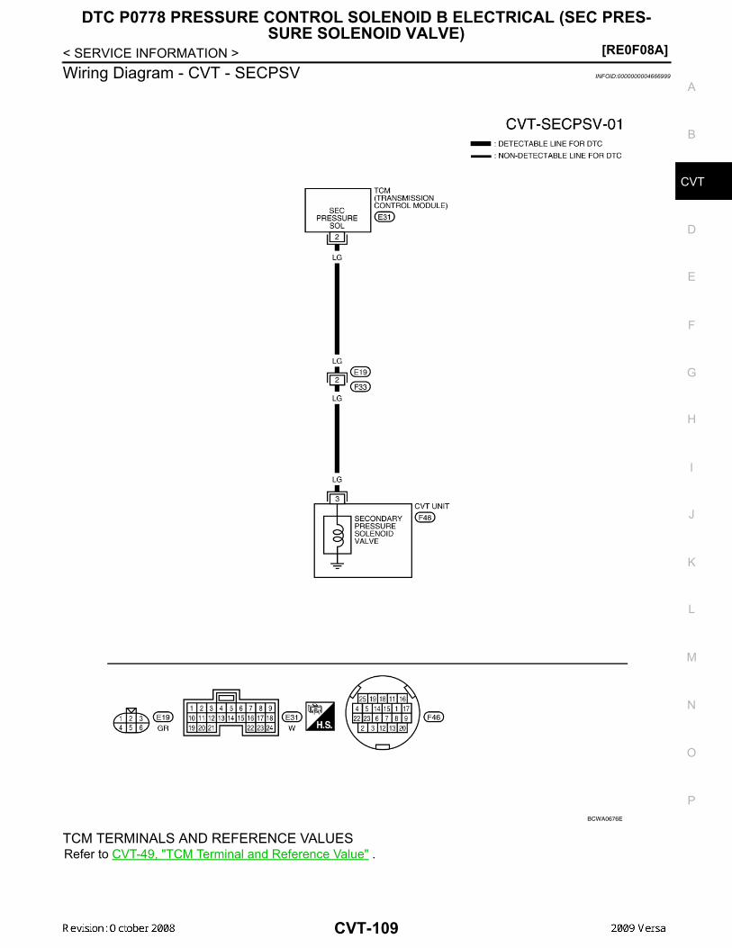
DTC P0778 PRESSURE CONTROL SOLENOID B ELECTRICAL (SEC PRES-SURE SOLENOID VALVE)
[RE0F08A]
D
E
F
G
H
I
J
K
L
M
A
B
VT
N
O
P
< SERVICE INFORMATION >
C
Wiring Diagram - CVT - SECPSV INFOID:0000000004666999
TCM TERMINALS AND REFERENCE VALUESRefer to CVT-49, "TCM Terminal and Reference Value" .
BCWA0676E
CVT-109

[RE0F08A]
DTC P0778 PRESSURE CONTROL SOLENOID B ELECTRICAL (SEC PRES-SURE SOLENOID VALVE)
< SERVICE INFORMATION >Diagnosis Procedure INFOID:0000000004667000
1. CHECK INPUT SIGNAL
With CONSULT-III1. Start engine.2. Select “MAIN SIGNALS” in “DATA MONITOR” mode for “TRANSMISSION” with CONSULT-III.3. Read out the value of “ISOLT3”.
Without CONSULT-III1. Start engine.2. Check voltage between TCM connector terminal and ground.
3. Turn ignition switch OFF.4. Disconnect TCM connector.5. Check if there is continuity between connector terminal and ground. OK or NG OK >> GO TO 5. NG >> GO TO 2.
2.CHECK PRESSURE CONTROL SOLENOID VALVE B (SECONDARY PRESSURE SOLENOID VALVE)CIRCUIT1. Turn ignition switch OFF.2. Disconnect TCM connector.3. Check resistance between TCM connector terminal and ground.
OK or NGOK >> GO TO 5.NG >> GO TO 3.
3.CHECK VALVE RESISTANCE
1. Turn ignition switch OFF.2. Disconnect CVT unit harness connector.
Item name Condition Display value (Approx.)
ISOLT3 Secondary pressure low - Secondary pressure high 0.8 - 0.0 A
Name Connector Terminal Condition Voltage (Approx.)
Pressure control so-lenoid valve B (Second-ary pres-sure solenoid valve)
E31 2 - ground
Release your foot from the accelerator pedal. 5.0 - 7.0 V
Press the accelerator pedal all the way down. 3.0 - 4.0 V
SCIA4506E
Solenoid valve Connector Terminal Resistance (Ap-prox.)
Pressure control solenoid valve B (Secondary pres-sure solenoid valve)
E31 2 - Ground 3 - 9 Ω
SCIA4507E
CVT-110

DTC P0778 PRESSURE CONTROL SOLENOID B ELECTRICAL (SEC PRES-SURE SOLENOID VALVE)
[RE0F08A]
D
E
F
G
H
I
J
K
L
M
A
B
VT
N
O
P
< SERVICE INFORMATION >
C
3. Check resistance between CVT unit harness connector terminaland ground.
OK or NGOK >> GO TO 4.NG >> Repair or replace damaged parts.
4.CHECK HARNESS BETWEEN TCM AND PRESSURE CONTROL SOLENOID VALVE B (SECONDARYPRESSURE SOLENOID VALVE)1. Turn ignition switch OFF.2. Disconnect TCM connector and CVT unit harness connector.3. Check continuity between TCM connector terminal and CVT unit
harness connector terminal.
4. If OK, check harness for short to ground and short to power.5. Reinstall any part removed.OK or NGOK >> GO TO 5.NG >> Repair or replace damaged parts.
5.CHECK DTC
Perform CVT-108, "DTC Confirmation Procedure" .OK or NGOK >> INSPECTION ENDNG >> GO TO 6.
6.CHECK TCM
1. Check TCM input/output signals. Refer to CVT-49, "TCM Terminal and Reference Value" .2. If NG, re-check TCM pin terminals for damage or loose connection with harness connector.OK or NGOK >> INSPECTION ENDNG >> 1. Repair or replace damaged parts.
2. Replace the transaxle assembly. Refer to CVT-182, "Removal and Installation" .
Component Inspection INFOID:0000000004667001
PRESSURE CONTROL SOLENOID VALVE B (SECONDARY PRESSURE SOLENOID VALVE)1. Turn ignition switch OFF.2. Disconnect CVT unit harness connector.
Solenoid valve Connector Terminal Resistance (Ap-prox.)
Pressure control solenoid valve B (Secondary pres-sure solenoid valve)
F46 3 - Ground 3 - 9 Ω
SCIA4688E
Item Connector Terminal Continuity
TCM connector E31 2YesCVT unit harness connec-
tor F46 3
SCIA4689E
CVT-111

[RE0F08A]
DTC P0778 PRESSURE CONTROL SOLENOID B ELECTRICAL (SEC PRES-SURE SOLENOID VALVE)
< SERVICE INFORMATION >3. Check resistance between CVT unit harness connector terminal
and ground.
4. If NG, replace the transaxle assembly. Refer to CVT-182,"Removal and Installation" .
Solenoid Valve Connector Terminal Resistance (Ap-prox.)
Pressure control sole-noid valve B (Secondary pressure solenoid valve)
F46 3 - Ground 3 - 9 Ω
SCIA4688E
CVT-112

DTC P0840 TRANSMISSION FLUID PRESSURE SENSOR A CIRCUIT (SEC PRESSURE SENSOR)
[RE0F08A]
D
E
F
G
H
I
J
K
L
M
A
B
VT
N
O
P
< SERVICE INFORMATION >
C
DTC P0840 TRANSMISSION FLUID PRESSURE SENSOR A CIRCUIT(SEC PRESSURE SENSOR)Description INFOID:0000000004667002
• The transmission fluid pressure sensor A (secondary pressure sensor) is included in the control valveassembly.
• The transmission fluid pressure sensor A (secondary pressure sensor) detects secondary pressure of CVTand sends TCM the signal.
CONSULT-III Reference Value in Data Monitor Mode INFOID:0000000004667003
Remarks: Specification data are reference values.
On Board Diagnosis Logic INFOID:0000000004667004
• This is an OBD-II self-diagnostic item.• Diagnostic trouble code “P0840 TR PRS SENS/A CIRC” with CONSULT-III is detected when TCM detects
an improper voltage drop when it receives the sensor signal.
Possible Cause INFOID:0000000004667005
• Transmission fluid pressure sensor A (Secondary pressure sensor)• Harness or connectors
(Switch circuit is open or shorted.)
DTC Confirmation Procedure INFOID:0000000004667006
NOTE:If “DTC Confirmation Procedure” has been previously performed, always turn ignition switch OFF andwait at least 10 seconds before performing the next test.After the repair, perform the following procedure to confirm the malfunction is eliminated.
WITH CONSULT-III1. Turn ignition switch ON and select “DATA MONITOR” mode for “TRANSMISSION” with CONSULT-III.2. Make sure that output voltage of line temperature sensor is within the range below.
ATF TEMP SEN: 1.0 - 2.0 VIf out of range, drive the vehicle to decrease the voltage (warm up the fluid) or stop engine toincrease the voltage (cool down the fluid)
3. Start engine and wait for at least 5 consecutive seconds.4. If DTC is detected, go to CVT-115, "Diagnosis Procedure" .
WITH GSTFollow the procedure “WITH CONSULT-III”.
Item name Condition Display value (Approx.)
SEC HYDR SEN“N” position idle
1.0 V
SEC PRESS 0.8 MPa
CVT-113

[RE0F08A]
DTC P0840 TRANSMISSION FLUID PRESSURE SENSOR A CIRCUIT (SEC PRESSURE SENSOR)
< SERVICE INFORMATION >Wiring Diagram - CVT - SECPS INFOID:0000000004667007
TCM TERMINALS AND REFERENCE VALUESRefer to CVT-49, "TCM Terminal and Reference Value".
BCWA0677E
CVT-114

DTC P0840 TRANSMISSION FLUID PRESSURE SENSOR A CIRCUIT (SEC PRESSURE SENSOR)
[RE0F08A]
D
E
F
G
H
I
J
K
L
M
A
B
VT
N
O
P
< SERVICE INFORMATION >
C
Diagnosis Procedure INFOID:0000000004667008
1.CHECK INPUT SIGNAL
With CONSULT-III1. Start engine.2. Select “ECU INPUT SIGNALS” in “DATA MONITOR” mode for “TRANSMISSION” with CONSULT-III.3. Start vehicle and read out the value of “SEC HYDR SEN”.
Without CONSULT-III1. Start engine.2. Check voltage between TCM connector terminal and ground.
OK or NGOK >> GO TO 5.NG >> GO TO 2.
2.CHECK SENSOR POWER AND SENSOR GROUND
1. Turn ignition switch ON. (Do not start engine)2. Check voltage between TCM connector terminals.
OK or NGOK >> GO TO 4.NG >> GO TO 3.
3. CHECK HARNESS BETWEEN TCM AND CVT UNIT HARNESS CONNECTOR (SENSOR POWER ANDSENSOR GROUND)1. Turn ignition switch OFF.2. Disconnect TCM connector and CVT unit harness connector.3. Check continuity between TCM connector terminals and CVT
unit harness connector terminals.
4. If OK, check harness for short to ground and short to power.5. Reinstall any part removed. OK or NG
Item name Condition Display value (Approx.)
SEC HYDR SEN “N” position idle 1.0 V
Name Connector Terminal Condition Voltage (Approx.)
Transmission fluid pressure sensor A (Secondary pressure sen-sor)
E32 37 - Ground “N” position idle 1.0 V
SCIA4508E
Item Connector Terminal Data (Ap-prox.)
TCM connector E32 46 - 42 5.0 V
SCIA2367E
Item Connector Terminal Continuity
TCM E32 42Yes
CVT unit harness connector F46 19
TCM E32 46Yes
CVT unit harness connector F46 20
SCIA4681E
CVT-115

[RE0F08A]
DTC P0840 TRANSMISSION FLUID PRESSURE SENSOR A CIRCUIT (SEC PRESSURE SENSOR)
< SERVICE INFORMATION > OK >> Replace TCM. Refer to CVT-12, "Service After Replacing TCM and Transaxle Assembly" . NG >> Repair open circuit or short to ground or short to power in harness or connectors.
4.CHECK HARNESS BETWEEN TCM AND TRANSMISSION FLUID PRESSURE SENSOR A (SECOND-ARY PRESSURE SENSOR)1. Turn ignition switch OFF.2. Disconnect TCM connector and CVT unit harness connector.3. Check continuity between TCM connector terminal and CVT unit
harness connector terminal.
4. If OK, check harness for short to ground and short to power.5. Reinstall any part removed.OK or NGOK >> GO TO 5.NG >> Repair open circuit or short to ground or short to power
in harness or connectors.5.CHECK DTC
Perform CVT-113, "DTC Confirmation Procedure" .OK or NGOK >> INSPECTION ENDNG >> GO TO 6.
6.CHECK TCM
1. Check TCM input/output signals. Refer to CVT-49, "TCM Terminal and Reference Value" .2. If NG, re-check TCM pin terminals for damage or loose connection with harness connector.OK or NGOK >> Replace the transaxle assembly. Refer to CVT-182, "Removal and Installation" .NG >> Repair or replace damaged parts.
Item Connector Terminal Continuity
TCM E32 37Yes
CVT unit harness connector F46 23
SCIA4690E
CVT-116

DTC P0841 PRESSURE SENSOR FUNCTION[RE0F08A]
D
E
F
G
H
I
J
K
L
M
A
B
VT
N
O
P
< SERVICE INFORMATION >
C
DTC P0841 PRESSURE SENSOR FUNCTIONDescription INFOID:0000000004667009
Using the engine load (throttle position), the primary pulley revolution speed, and the secondary pulley revolu-tion speed as input signal, TCM changes the operating pressure of the primary pulley and the secondary pul-ley and changes the groove width of the pulley to control the gear ratio.
CONSULT-III Reference Value in Data Monitor Mode INFOID:0000000004667010
Remarks: Specification data are reference values.
On Board Diagnosis Logic INFOID:0000000004667011
• This is not an OBD-II self-diagnostic item.• Diagnostic trouble code “P0841 PRESS SEN/FNCTN” with CONSULT-III is detected when correlation
between the values of the secondary pressure sensor and the primary pressure sensor is out of specifica-tion.
Possible Cause INFOID:0000000004667012
• Transmission fluid pressure sensor A (Secondary pressure sensor)• Transmission fluid pressure sensor B (Primary pressure sensor)• Harness or connectors
(Sensor circuit is open or shorted.)
DTC Confirmation Procedure INFOID:0000000004667013
CAUTION:Always drive vehicle at a safe speed.NOTE:If “DTC Confirmation Procedure” has been previously performed, always turn ignition switch OFF andwait at least 10 seconds before performing the next test.After the repair, perform the following procedure to confirm the malfunction is eliminated.
WITH CONSULT-III1. Turn ignition switch ON and select “DATA MONITOR” mode for “TRANSMISSION” with CONSULT-III.2. Start engine and maintain the following conditions for at least 12 consecutive seconds.
VEHICLE SPEED: 40 km/h (25 MPH) More thanRANGE: “D” position
3. If DTC is detected, go to CVT-117, "Diagnosis Procedure".
Diagnosis Procedure INFOID:0000000004667014
1.CHECK CAN COMMUNICATION LINE
Perform the self-diagnosis. Refer to CVT-51, "CONSULT-III Function (TRANSMISSION)".Is any malfunction of the “U1000 CAN COMM CIRCUIT” indicated?YES >> Check CAN communication line. Refer to CVT-60.NO >> GO TO 2.
2.CHECK INPUT SIGNALS
With CONSULT-III1. Start engine.2. Select “ECU INPUT SIGNALS” in “DATA MONITOR” mode for “TRANSMISSION” with CONSULT-III.3. Start vehicle and read out the value of “SEC HYDR SEN” and “PRI HYDR SEN”.
Item name Condition Display value (Approx.)
PRI HYDR SEN“N” position idle
0.7 V
SEC HYDR SEN 1.0 V
CVT-117
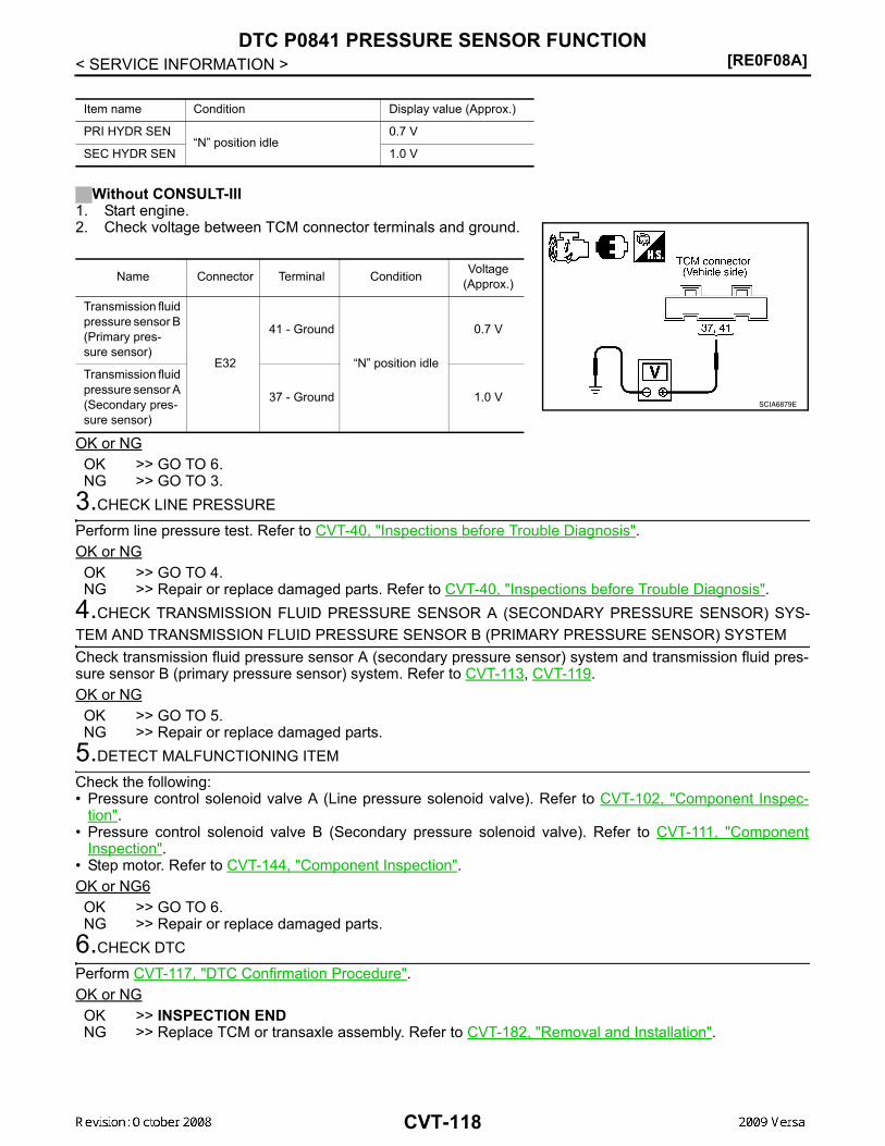
[RE0F08A]DTC P0841 PRESSURE SENSOR FUNCTION
< SERVICE INFORMATION >
Without CONSULT-III1. Start engine.2. Check voltage between TCM connector terminals and ground.
OK or NGOK >> GO TO 6.NG >> GO TO 3.
3.CHECK LINE PRESSURE
Perform line pressure test. Refer to CVT-40, "Inspections before Trouble Diagnosis".OK or NGOK >> GO TO 4.NG >> Repair or replace damaged parts. Refer to CVT-40, "Inspections before Trouble Diagnosis".
4.CHECK TRANSMISSION FLUID PRESSURE SENSOR A (SECONDARY PRESSURE SENSOR) SYS-TEM AND TRANSMISSION FLUID PRESSURE SENSOR B (PRIMARY PRESSURE SENSOR) SYSTEMCheck transmission fluid pressure sensor A (secondary pressure sensor) system and transmission fluid pres-sure sensor B (primary pressure sensor) system. Refer to CVT-113, CVT-119.OK or NGOK >> GO TO 5.NG >> Repair or replace damaged parts.
5.DETECT MALFUNCTIONING ITEM
Check the following:• Pressure control solenoid valve A (Line pressure solenoid valve). Refer to CVT-102, "Component Inspec-
tion".• Pressure control solenoid valve B (Secondary pressure solenoid valve). Refer to CVT-111, "Component
Inspection".• Step motor. Refer to CVT-144, "Component Inspection".OK or NG6OK >> GO TO 6.NG >> Repair or replace damaged parts.
6.CHECK DTC
Perform CVT-117, "DTC Confirmation Procedure".OK or NGOK >> INSPECTION ENDNG >> Replace TCM or transaxle assembly. Refer to CVT-182, "Removal and Installation".
Item name Condition Display value (Approx.)
PRI HYDR SEN“N” position idle
0.7 V
SEC HYDR SEN 1.0 V
Name Connector Terminal Condition Voltage (Approx.)
Transmission fluid pressure sensor B (Primary pres-sure sensor)
E32
41 - Ground
“N” position idle
0.7 V
Transmission fluid pressure sensor A (Secondary pres-sure sensor)
37 - Ground 1.0 VSCIA6879E
CVT-118

DTC P0845 TRANSMISSION FLUID PRESSURE SENSOR B CIRCUIT (PRI PRESSURE SENSOR)
[RE0F08A]
D
E
F
G
H
I
J
K
L
M
A
B
VT
N
O
P
< SERVICE INFORMATION >
C
DTC P0845 TRANSMISSION FLUID PRESSURE SENSOR B CIRCUIT (PRIPRESSURE SENSOR)Description INFOID:0000000004667015
• The transmission fluid pressure sensor B (primary pressure sensor) is included in the control valve assem-bly.
• The transmission fluid pressure sensor B (primary pressure sensor) detects primary pressure of CVT andsends TCM the signal.
CONSULT-III Reference Value in Data Monitor Mode INFOID:0000000004667016
Remarks: Specification data are reference values.
On Board Diagnosis Logic INFOID:0000000004667017
• This is an OBD-II self-diagnostic item.• Diagnostic trouble code “P0845 TR PRS SENS/B CIRC” with CONSULT-III is detected under the following
conditions.- When TCM detects an improper voltage drop when it receives the sensor signal.- When TCM compares target value with monitor value and detects an irregularity.
Possible Cause INFOID:0000000004667018
• Transmission fluid pressure sensor B (Primary pressure sensor)• Harness or connectors
(Sensor circuit is open or shorted.)
DTC Confirmation Procedure INFOID:0000000004667019
NOTE:If “DTC Confirmation Procedure” has been previously performed, always turn ignition switch OFF andwait at least 10 seconds before performing the next test.After the repair, perform the following procedure to confirm the malfunction is eliminated.
WITH CONSULT-III1. Turn ignition switch ON and select “DATA MONITOR” mode for “TRANSMISSION” with CONSULT-III.2. Make sure that output voltage of line temperature sensor is within the range below.
ATF TEMP SEN: 1.0 - 2.0 VIf out of range, drive the vehicle to decrease the voltage (warm up the fluid) or stop engine toincrease the voltage (cool down the fluid)
3. Start engine and wait for at least 5 consecutive seconds.4. If DTC is detected, go to CVT-121, "Diagnosis Procedure" .
WITH GSTFollow the procedure “WITH CONSULT-III”.
Item name Condition Display value (Approx.)
PRI HYDR SEN “N” position idle 0.7 V
CVT-119

[RE0F08A]
DTC P0845 TRANSMISSION FLUID PRESSURE SENSOR B CIRCUIT (PRI PRESSURE SENSOR)
< SERVICE INFORMATION >Wiring Diagram - CVT - PRIPS INFOID:0000000004667020
CM TERMINALS AND REFERENCE VALUESRefer to CVT-49, "TCM Terminal and Reference Value".
BCWA0678E
CVT-120

DTC P0845 TRANSMISSION FLUID PRESSURE SENSOR B CIRCUIT (PRI PRESSURE SENSOR)
[RE0F08A]
D
E
F
G
H
I
J
K
L
M
A
B
VT
N
O
P
< SERVICE INFORMATION >
C
Diagnosis Procedure INFOID:0000000004667021
1.CHECK INPUT SIGNAL
With CONSULT-III1. Start engine.2. Select “ECU INPUT SIGNALS” in “DATA MONITOR” mode for “TRANSMISSION” with CONSULT-III.3. Start vehicle and read out the value of “PRI HYDR SEN”.
Without CONSULT-III1. Start engine.2. Check voltage between TCM connector terminal and ground.
OK or NGOK >> GO TO 5.NG >> GO TO 2.
2.CHECK SENSOR POWER AND SENSOR GROUND
1. Turn ignition switch ON. (Do not start engine)2. Check voltage between TCM connector terminals.
OK or NGOK >> GO TO 4.NG >> GO TO 3.
3. CHECK HARNESS BETWEEN TCM AND CVT UNIT HARNESS CONNECTOR (SENSOR POWER ANDSENSOR GROUND)1. Turn ignition switch OFF.2. Disconnect TCM connector and CVT unit harness connector.3. Check continuity between TCM connector terminals and CVT
unit harness connector terminals.
4. If OK, check harness for short to ground and short to power.5. Reinstall any part removed.
Item name Condition Display value (Approx.)
PRI HYDR SEN “N” position idle 0.7 V
Name Connector Terminal Condition Voltage (Approx.)
Transmis-sion fluid pressure sensor B (Primary pressure sensor)
E32 41 - Ground “N” position idle 0.7 V
SCIA4509E
Item Connector Terminal Data (Ap-prox.)
TCM connector E32 46 - 42 5.0 V
SCIA2367E
Item Connector Terminal Continuity
TCM E32 42Yes
CVT unit harness connector F46 19
TCM E32 46Yes
CVT unit harness connector F46 20
SCIA4681E
CVT-121

[RE0F08A]
DTC P0845 TRANSMISSION FLUID PRESSURE SENSOR B CIRCUIT (PRI PRESSURE SENSOR)
< SERVICE INFORMATION > OK or NG OK >> Replace TCM. Refer to CVT-12, "Service After Replacing TCM and Transaxle Assembly" . NG >> Repair open circuit or short to ground or short to power in harness or connectors.
4.CHECK HARNESS BETWEEN TCM AND TRANSMISSION FLUID PRESSURE SENSOR B (PRIMARYPRESSURE SENSOR)1. Turn ignition switch OFF.2. Disconnect TCM connector and CVT unit harness connector.3. Check continuity between TCM connector terminal and CVT unit
harness connector terminal.
4. If OK, check harness for short to ground and short to power.5. Reinstall any part removed.OK or NGOK >> GO TO 5.NG >> Repair open circuit or short to ground or short to power
in harness or connectors.5.CHECK DTC
Perform CVT-119, "DTC Confirmation Procedure" .OK or NGOK >> INSPECTION ENDNG >> GO TO 6.
6.CHECK TCM
1. Check TCM input/output signals. Refer to CVT-49, "TCM Terminal and Reference Value" .2. If NG, re-check TCM pin terminals for damage or loose connection with harness connector.OK or NGOK >> Replace the transaxle assembly. Refer to CVT-182, "Removal and Installation" .NG >> Repair or replace damaged parts.
Item Connector Terminal Continuity
TCM E32 41Yes
CVT unit harness connector F46 25
SCIA4691E
CVT-122

DTC P0868 SECONDARY PRESSURE DOWN[RE0F08A]
D
E
F
G
H
I
J
K
L
M
A
B
VT
N
O
P
< SERVICE INFORMATION >
C
DTC P0868 SECONDARY PRESSURE DOWNDescription INFOID:0000000004667022
• The pressure control solenoid valve B (secondary pressure solenoid valve) is included in the control valveassembly.
• The pressure control solenoid valve B (secondary pressure solenoid valve) regulates the secondary pres-sure to suit the driving condition in response to a signal sent from the TCM.
CONSULT-III Reference Value in Data Monitor Mode INFOID:0000000004667023
Remarks: Specification data are reference values.
On Board Diagnosis Logic INFOID:0000000004667024
• This is not an OBD-II self-diagnostic item. • Diagnostic trouble code “P0868 SEC/PRESS DOWN” with CONSULT-III is detected when secondary fluid
pressure is too low compared with the commanded value while driving.
Possible Cause INFOID:0000000004667025
• Harness or connectors(Solenoid circuit is open or shorted.)
• Pressure control solenoid valve B (Secondary pressure solenoid valve) system• Transmission fluid pressure sensor A (Secondary pressure sensor)• Line pressure control system
DTC Confirmation Procedure INFOID:0000000004667026
CAUTION:Always drive vehicle at a safe speed.NOTE:If “DTC Confirmation Procedure” has been previously performed, always turn ignition switch OFF andwait at least 10 seconds before performing the next test.After the repair, perform the following procedure to confirm the malfunction is eliminated.
WITH CONSULT-III1. Turn ignition switch ON and select “DATA MONITOR” mode for “TRANSMISSION” with CONSULT-III.2. Make sure that output voltage of CVT fluid temperature sensor is within the range below.
ATF TEMP SEN: 1.0 - 2.0 VIf out of range, drive the vehicle to decrease the voltage (warm up the fluid) or stop engine toincrease the voltage (cool down the fluid)
3. Start engine and maintain the following conditions for at least 10 consecutive seconds.VEHICLE SPEED (accelerate slowly): 0 → 50 km/h (31 MPH)ACC PEDAL OPEN: 0.5/8 - 1.0/8RANGE: “D” position
4. If DTC is detected, go to CVT-123, "Diagnosis Procedure".
Diagnosis Procedure INFOID:0000000004667027
1.CHECK INPUT SIGNAL
With CONSULT-III1. Start engine.2. Select “MAIN SIGNALS” in “DATA MONITOR” mode for “TRANSMISSION” with CONSULT-III.3. Start vehicle and read out the value of “SEC PRESS”.
Item name Condition Display value (Approx.)
SEC PRESS “N” position idle 0.8 MPa
Item name Condition Display value (Approx.)
SEC PRESS “N” position idle 0.8 MPa
CVT-123

[RE0F08A]DTC P0868 SECONDARY PRESSURE DOWN
< SERVICE INFORMATION >OK or NGOK >> GO TO 5.NG >> GO TO 2.
2.CHECK LINE PRESSURE
Perform line pressure test. Refer to CVT-40, "Inspections before Trouble Diagnosis".OK or NGOK >> GO TO 3.NG >> Repair or replace damaged parts. Refer to CVT-40, "Inspections before Trouble Diagnosis".
3.DETECT MALFUNCTIONING ITEM
Check the following:• Pressure control solenoid valve B (Secondary pressure solenoid valve). Refer to CVT-111, "Component
Inspection".• Pressure control solenoid valve A (Line pressure solenoid valve). Refer to CVT-102, "Component Inspec-
tion".OK or NGOK >> GO TO 4.NG >> Repair or replace damaged parts.
4.CHECK TRANSMISSION FLUID PRESSURE SENSOR A (SECONDARY PRESSURE SENSOR) SYS-TEMCheck transmission fluid pressure sensor A (secondary pressure sensor) system. Refer to CVT-113.OK or NGOK >> GO TO 5.NG >> Repair or replace damaged parts.
5.DETECT MALFUNCTIONING ITEM
Check the following:• Power supply and ground circuit for TCM. Refer to CVT-126, "Wiring Diagram - CVT - POWER".• The TCM pin terminals for damage or loose connection with harness connector.OK or NGOK >> GO TO 6.NG >> Repair or replace damaged parts.
6.CHECK DTC
Perform CVT-123, "DTC Confirmation Procedure".OK or NGOK >> INSPECTION ENDNG >> Replace the transaxle assembly. Refer to CVT-182, "Removal and Installation".
CVT-124

DTC P1701 TRANSMISSION CONTROL MODULE (POWER SUPPLY)[RE0F08A]
D
E
F
G
H
I
J
K
L
M
A
B
VT
N
O
P
< SERVICE INFORMATION >
C
DTC P1701 TRANSMISSION CONTROL MODULE (POWER SUPPLY)Description INFOID:0000000004667028
When the power supply to the TCM is cut OFF, for example because the battery is removed, and the self-diag-nosis memory function stops, malfunction is detected.NOTE:Since “P1701 TCM-POWER SUPPLY” will be indicated when replacing TCM, perform diagnosis aftererasing “SELF-DIAG RESULTS”
On Board Diagnosis Logic INFOID:0000000004667029
• This is not an OBD-II self-diagnostic item.• Diagnostic trouble code “P1701 TCM-POWER SUPPLY” with CONSULT-III is detected when TCM does not
receive the voltage signal from the battery power supply.• This is not a malfunction message. (Whenever shutting OFF a power supply to the TCM, this message
appears on the screen.)
Possible Cause INFOID:0000000004667030
Harness or connectors(Battery or ignition switch and TCM circuit is open or shorted.)
DTC Confirmation Procedure INFOID:0000000004667031
NOTE:If “DTC Confirmation Procedure” has been previously conducted, always turn ignition switch OFF andwait at least 10 seconds before conducting the next test.After the repair, perform the following procedure to confirm the malfunction is eliminated.
WITH CONSULT-III1. Turn ignition switch ON. (Do not start engine.)2. Select “DATA MONITOR” mode for “TRANSMISSION” with CONSULT-III.3. Wait for at least 2 consecutive seconds.4. If DTC is detected, go to CVT-127, "Diagnosis Procedure" .
CVT-125

[RE0F08A]DTC P1701 TRANSMISSION CONTROL MODULE (POWER SUPPLY)
< SERVICE INFORMATION >Wiring Diagram - CVT - POWER INFOID:0000000004667032
TCM TERMINALS AND REFERENCE VALUESRefer to CVT-49, "TCM Terminal and Reference Value" .
BCWA0679E
CVT-126

DTC P1701 TRANSMISSION CONTROL MODULE (POWER SUPPLY)[RE0F08A]
D
E
F
G
H
I
J
K
L
M
A
B
VT
N
O
P
< SERVICE INFORMATION >
C
Diagnosis Procedure INFOID:0000000004667033
1.CHECK DTC
1. Turn ignition switch ON. (Do not start engine.)2. Select “SELF-DIAG RESULTS” mode for “TRANSMISSION” with CONSULT-III.3. Erase self-diagnostic results. Refer to CVT-30, "OBD-II Diagnostic Trouble Code (DTC)" .4. Turn ignition switch OFF, and wait for 5 seconds or more.5. Start engine.6. Confirm self-diagnostic results again. Refer to CVT-51, "CONSULT-III Function (TRANSMISSION)" .Is the “P1701 TCM-POWER SUPPLY” displayed?YES >> GO TO 2.NO >> INSPECTION END
2.CHECK TCM POWER SOURCE, STEP 1
1. Turn ignition switch OFF.2. Check voltage between TCM connector terminal and ground.
OK or NGOK >> GO TO 3.NG >> GO TO 4.
3.CHECK TCM POWER SOURCE, STEP 2
1. Turn ignition switch ON. (Do not start engine.)2. Check voltage between TCM connector terminals and ground.
OK or NGOK >> GO TO 5.NG >> GO TO 4.
4.DETECT MALFUNCTIONING ITEM
Check the following.• Harness for short or open between battery and TCM connector terminal 28• Harness for short or open between ignition switch and TCM connector terminal 10, 19
Name Connector Terminal Condition Voltage (Approx.)
Power supply (memory back-up)
E32 28 - Ground Always Battery voltage
SCIA4783E
Name Connector Terminal Condition Voltage (Approx.)
Power supply
E31
10 - Ground
Battery voltage
0 V
Power supply 19 - Ground
Battery voltage
0 V
Power supply (memory back-up)
E32 28 - Ground Always Battery voltage
SCIA4784E
CVT-127

[RE0F08A]DTC P1701 TRANSMISSION CONTROL MODULE (POWER SUPPLY)
< SERVICE INFORMATION >• 10 A fuse (No.49, located in the IPDM E/R) • 20 A fuse (No.53, located in the IPDM E/R) • Ignition switch. Refer to PG-3 .OK or NGOK >> GO TO 5.NG >> Repair or replace damaged parts.
5.CHECK TCM GROUND CIRCUIT
1. Turn ignition switch OFF.2. Disconnect TCM connector.3. Check continuity between TCM connector terminals and ground.
OK or NGOK >> GO TO 6.NG >> Repair open circuit or short to ground or short to power
in harness or connectors.
6.CHECK DTC
Perform CVT-125, "DTC Confirmation Procedure" .OK or NGOK >> INSPECTION ENDNG >> GO TO 7.
7.CHECK TCM
1. Check TCM input/output signals. Refer to CVT-49, "TCM Terminal and Reference Value" .2. If NG, re-check TCM pin terminals for damage or loose connection with harness connector.OK or NGOK >> INSPECTION ENDNG >> Repair or replace damaged parts.
Name Connector Terminal Continuity
Ground E3225
Yes48
SCIA2671E
CVT-128

DTC P1705 THROTTLE POSITION SENSOR[RE0F08A]
D
E
F
G
H
I
J
K
L
M
A
B
VT
N
O
P
< SERVICE INFORMATION >
C
DTC P1705 THROTTLE POSITION SENSORDescription INFOID:0000000004667034
Electric throttle control actuator consists of throttle control motor, accelerator pedal position sensor, throttleposition sensor etc. The actuator sends a signal to the ECM, and ECM sends the signal to TCM with CANcommunication.
CONSULT-III Reference Value in Data Monitor Mode INFOID:0000000004667035
Remarks: Specification data are reference values.
On Board Diagnosis Logic INFOID:0000000004667036
• This is not an OBD-II self-diagnostic item.• Diagnostic trouble code “P1705 TP SEN/CIRC A/T” with CONSULT-III is detected when TCM does not
receive the proper accelerator pedal position signals (input by CAN communication) from ECM.
Possible Cause INFOID:0000000004667037
• ECM• Harness or connectors
(CAN communication line is open or shorted.)
DTC Confirmation Procedure INFOID:0000000004667038
NOTE:If “DTC Confirmation Procedure” has been previously performed, always turn ignition switch OFF andwait at least 10 seconds before performing the next test.After the repair, perform the following procedure to confirm the malfunction is eliminated.
WITH CONSULT-III1. Turn ignition switch ON. (Do not start engine.)2. Select “DATA MONITOR” mode for “TRANSMISSION” with CONSULT-III.3. Depress accelerator pedal fully and release it, then wait for 5 seconds.4. If DTC is detected, go to CVT-129, "Diagnosis Procedure".
Diagnosis Procedure INFOID:0000000004667039
1.CHECK CAN COMMUNICATION LINE
Perform the self-diagnosis check. Refer to CVT-51, "CONSULT-III Function (TRANSMISSION)".Is any malfunction of the “U1000 CAN COMM CIRCUIT” indicated?YES >> Check the CAN communication line. Refer to CVT-60.NO >> GO TO 2.
2.CHECK INPUT SIGNAL
With CONSULT-III1. Turn ignition switch ON. (Do not start engine.)2. Select “ECU INPUT SIGNALS” in “DATA MONITOR” mode for “TRANSMISSION” with CONSULT-III.3. Read out the value of “ACC PEDAL OPEN”.
OK or NG
Item name Condition Display value (Approx.)
ACC PEDAL OPEN Released accelerator pedal - Fully depressed accelerator pedal 0.0/8 - 8.0/8
Item name Condition Display value (Approx.)
ACC PEDAL OPEN
Release accelerator ped-al.↓
Fully depressed acceler-ator pedal
0.0/8↓
8.0/8
CVT-129

[RE0F08A]DTC P1705 THROTTLE POSITION SENSOR
< SERVICE INFORMATION >OK >> GO TO 4.NG >> GO TO 3.
3.CHECK DTC WITH ECM
With CONSULT-III1. Turn ignition switch ON. (Do not start engine.)2. Select “SELF-DIAG RESULTS” mode for “ENGINE” with CONSULT-III. Refer to EC-604, "CONSULT-III
Function (ENGINE)".OK or NGOK >> GO TO 4.NG >> Check the DTC Detected Item. Go to EC-604, "CONSULT-III Function (ENGINE)".
4.CHECK DTC
Perform CVT-129, "DTC Confirmation Procedure".OK or NGOK >> INSPECTION ENDNG >> Repair or replace damaged parts.
CVT-130

DTC P1722 ESTM VEHICLE SPEED SIGNAL[RE0F08A]
D
E
F
G
H
I
J
K
L
M
A
B
VT
N
O
P
< SERVICE INFORMATION >
C
DTC P1722 ESTM VEHICLE SPEED SIGNALDescription INFOID:0000000004667040
The vehicle speed signal is transmitted from ABS actuator and electric unit (control unit) to TCM by CAN com-munication line.
CONSULT-III Reference Value in Data Monitor Mode INFOID:0000000004667041
Remarks: Specification data are reference values.
On Board Diagnosis Logic INFOID:0000000004667042
• This is not an OBD-II self-diagnostic item.• Diagnostic trouble code “P1722 ESTM VEH SPD SIG” with CONSULT-III is detected when TCM does not
receive the proper vehicle speed signal (input by CAN communication) from ABS actuator and electric unit(control unit).
Possible Cause INFOID:0000000004667043
• Harness or connectors(Sensor circuit is open or shorted.)
• ABS actuator and electric unit (control unit)
DTC Confirmation Procedure INFOID:0000000004667044
CAUTION:Always drive vehicle at a safe speed.NOTE:If “DTC Confirmation Procedure” has been previously performed, always turn ignition switch OFF andwait at least 10 seconds before performing the next test.After the repair, touch “ERASE” on “SELF-DIAG RESULTS” and then perform the following procedure to con-firm the malfunction is eliminated.
WITH CONSULT-III1. Turn ignition switch ON. (Do not start engine.)2. Select “DATA MONITOR” mode for “TRANSMISSION” with CONSULT-III.3. Start engine and maintain the following conditions for at least 5 consecutive seconds.
ACC PEDAL OPEN: 1.0/8 or lessVEHICLE SPEED SE: 30 km/h (17 MPH) or more
4. If DTC is detected, go to CVT-131, "Diagnosis Procedure".
Diagnosis Procedure INFOID:0000000004667045
1.CHECK CAN COMMUNICATION LINE
Perform the self-diagnosis check. Refer to CVT-51, "CONSULT-III Function (TRANSMISSION)".Is any malfunction of the “U1000 CAN COMM CIRCUIT” indicated?YES >> Check CAN communication line. Refer to CVT-60.NO >> GO TO 2.
2.CHECK ABS ACTUATOR AND ELECTRIC UNIT (CONTROL UNIT)
Perform ABS actuator and electric unit (control unit) self-diagnosis check. Refer to BRC-18, "CONSULT-IIIFunction (ABS)".OK or NGOK >> GO TO 3.NG >> Repair or replace damaged parts.
Item name Condition Display value
ESTM VSP SIGDuring driving Approximately matches the speedometer reading.
VEHICLE SPEED
CVT-131

[RE0F08A]DTC P1722 ESTM VEHICLE SPEED SIGNAL
< SERVICE INFORMATION >
3.CHECK INPUT SIGNALS
With CONSULT-III1. Start engine.2. Select “SELECTION FROM MENU” in “DATA MONITOR” mode for “TRANSMISSION” with CONSULT-III.3. Drive vehicle and read out the value of “VEHICLE SPEED” and “ESTM VSP SIG”.
4. Check if there is a great difference between the two values.
OK or NGOK >> GO TO 5.NG >> GO TO 4.
4.CHECK TCM
Check TCM input/output signals. Refer to CVT-49, "TCM Terminal and Reference Value".OK or NGOK >> GO TO 5.NG >> Repair or replace damaged parts.
5.CHECK DTC
Perform CVT-131, "DTC Confirmation Procedure".OK or NGOK >> INSPECTION ENDNG >> GO TO 2.
Item name Condition Display value
ESTM VSP SIGDuring driving Approximately matches
the speedometer reading.VEHICLE SPEED
CVT-132

DTC P1723 CVT SPEED SENSOR FUNCTION[RE0F08A]
D
E
F
G
H
I
J
K
L
M
A
B
VT
N
O
P
< SERVICE INFORMATION >
C
DTC P1723 CVT SPEED SENSOR FUNCTIONDescription INFOID:0000000004667046
• The input speed sensor (primary speed sensor) is included in the control valve assembly.• The vehicle speed sensor CVT [output speed sensor (secondary speed sensor)] detects the revolution of the
idler gear and generates a pulse signal. The pulse signal is sent to the TCM, which converts it into vehiclespeed.
• The input speed sensor (primary speed sensor) detects the primary pulley revolution speed and sends a sig-nal to the TCM.
On Board Diagnosis Logic INFOID:0000000004667047
• This is not an OBD-II self-diagnostic item.• Diagnostic trouble code “P1723 CVT SPD SEN/FNCTN” with CONSULT-III is detected when there is a great
difference between the vehicle speed signal and the secondary speed sensor signal.CAUTION:One of the “P0720 VEH SPD SEN/CIR AT”, the “P0715 INPUT SPD SEN/CIRC” or the “P0725 ENGINESPEED SIG“ is displayed with the DTC at the same time.
Possible Cause INFOID:0000000004667048
• Harness or connectors(Sensor circuit is open or shorted.)
• Output speed sensor (Secondary speed sensor)• Input speed sensor (Primary speed sensor)• Engine speed signal system
DTC Confirmation Procedure INFOID:0000000004667049
CAUTION:Always drive vehicle at a safe speed.NOTE:If “DTC Confirmation Procedure” has been previously performed, always turn ignition switch OFF andwait at least 10 seconds before performing the next test.After the repair, touch “ERASE” on “SELF-DIAG RESULTS” and then perform the following procedure to con-firm the malfunction is eliminated.
WITH CONSULT-III1. Turn ignition switch ON and select “DATA MONITOR” mode for “TRANSMISSION” with CONSULT-III.2. Start engine and maintain the following conditions for at least 5 consecutive seconds.
VEHICLE SPEED SE: 10 km/h (6 MPH) or moreACC PEDAL OPEN: More than 1.0/8RANGE: “D” positionENG SPEED: 450 rpm or moreDriving location: Driving the vehicle uphill (increased engine load) will help maintain the drivingconditions required for this test.
3. If DTC is detected, go to CVT-133, "Diagnosis Procedure".
Diagnosis Procedure INFOID:0000000004667050
1.CHECK STEP MOTOR FUNCTION
Perform the self-diagnosis check. Refer to CVT-51, "CONSULT-III Function (TRANSMISSION)".Is a malfunction in the step motor function indicated in the results?YES >> Repair or replace damaged parts. (Check the step motor function. Refer to CVT-145.)NO >> GO TO 2.
2.CHECK OUTPUT SPEED SENSOR (SECONDARY SPEED SENSOR SYSTEM) AND INPUT SPEEDSENSOR (PRIMARY SPEED SENSOR) SYSTEMCheck output speed sensor (secondary speed sensor) system and input speed sensor (primary speed sensor)system. Refer to CVT-84, CVT-80.
CVT-133

[RE0F08A]DTC P1723 CVT SPEED SENSOR FUNCTION
< SERVICE INFORMATION >OK or NGOK >> GO TO 3.NG >> Repair or replace damaged parts.
3.CHECK ENGINE SPEED SIGNAL SYSTEM
Check engine speed signal system. Refer to CVT-89.OK or NGOK >> GO TO 4.NG >> Repair or replace damaged parts. Refer to EC-996, "Component Description".
4.DETECT MALFUNCTIONING ITEM
Check the following:• Power supply and ground circuit for TCM. Refer to CVT-125.• The TCM pin terminals for damage or loose connection with harness connector.OK or NGOK >> GO TO 5.NG >> Repair or replace damaged parts.
5.CHECK DTC
Perform CVT-133, "DTC Confirmation Procedure".OK or NGOK >> INSPECTION ENDNG >> Replace TCM or transaxle assembly. Refer to CVT-12, "Service After Replacing TCM and Tran-
saxle Assembly", CVT-182, "Removal and Installation".
CVT-134

DTC P1726 ELECTRIC THROTTLE CONTROL SYSTEM[RE0F08A]
D
E
F
G
H
I
J
K
L
M
A
B
VT
N
O
P
< SERVICE INFORMATION >
C
DTC P1726 ELECTRIC THROTTLE CONTROL SYSTEMDescription INFOID:0000000004667051
Electric throttle control actuator consists of throttle control motor, accelerator pedal position sensor, throttleposition sensor etc. The actuator sends a signal to the ECM, and ECM sends the signal to TCM with CANcommunication.
On Board Diagnosis Logic INFOID:0000000004667052
• This is not an OBD-II self-diagnostic item.• Diagnostic trouble code “P1726 ELEC TH CONTROL” with CONSULT-III is detected when the electronically
controlled throttle for ECM is malfunctioning.
Possible Cause INFOID:0000000004667053
Harness or connectors(Sensor circuit is open or shorted.)
DTC Confirmation Procedure INFOID:0000000004667054
NOTE:If “DTC Confirmation Procedure” has been previously performed, always turn ignition switch OFF andwait at least 10 seconds before performing the next test.After the repair, touch “ERASE” on “SELF-DIAG RESULTS” and then perform the following procedure to con-firm the malfunction is eliminated.
WITH CONSULT-III1. Turn ignition switch ON. (Do not start engine.)2. Select “DATA MONITOR” mode for “TRANSMISSION” with CONSULT-III.3. Start engine and let it idle for 5 second.4. If DTC is detected, go to CVT-135, "Diagnosis Procedure".
Diagnosis Procedure INFOID:0000000004667055
1.CHECK DTC WITH ECM
With CONSULT-III1. Turn ignition switch ON. (Do not start engine.)2. Select “SELF-DIAG RESULTS” mode for “ENGINE” with CONSULT-III. Refer to EC-604, "CONSULT-III
Function (ENGINE)".OK or NGOK >> GO TO 2.NG >> Check the DTC Detected Item. Refer to EC-604, "CONSULT-III Function (ENGINE)".
• If CAN communication line is detected, go to CVT-60.2.CHECK DTC
Perform CVT-135, "DTC Confirmation Procedure".OK or NGOK >> INSPECTION ENDNG >> GO TO 3.
3.DETECT MALFUNCTIONING ITEM
Check the following:• The TCM pin terminals for damage or loose connection with harness connector.OK or NGOK >> Replace TCM. Refer to CVT-12, "Service After Replacing TCM and Transaxle Assembly".NG >> Repair or replace damaged parts.
CVT-135
[RE0F08A]DTC P1740 LOCK-UP SELECT SOLENOID VALVE CIRCUIT
< SERVICE INFORMATION >DTC P1740 LOCK-UP SELECT SOLENOID VALVE CIRCUITDescription INFOID:0000000004667056
• The lock-up select solenoid valve is included in the control valve assembly.• The lock-up select solenoid valve controls lock-up clutch pressure or forward clutch pressure (reverse brake
pressure).• When controlling lock-up clutch, the valve is turned OFF. When controlling forward clutch, it is turned ON.
CONSULT-III Reference Value in Data Monitor Mode INFOID:0000000004667057
On Board Diagnosis Logic INFOID:0000000004667058
• This is an OBD-II self-diagnostic item.• Diagnostic trouble code “P1740 LU-SLCT SOL/CIRC” with CONSULT-III is detected under the following con-
ditions.- When TCM compares target value with monitor value and detects an irregularity.
Possible Cause INFOID:0000000004667059
• Lock-up select solenoid valve• Harness or connectors
(Solenoid circuit is open or shorted.)
DTC Confirmation Procedure INFOID:0000000004667060
CAUTION:Always drive vehicle at a safe speed.NOTE:If “DTC Confirmation Procedure” has been previously performed, always turn ignition switch OFF andwait at least 10 seconds before performing the next test.After the repair, touch “ERASE” on “SELF-DIAG RESULTS” and then perform the following procedure to con-firm the malfunction is eliminated.
WITH CONSULT-III1. Turn ignition switch ON. (Do not start engine.)2. Select “DATA MONITOR” mode for “TRANSMISSION” with CONSULT-III.3. Start engine and maintain the following conditions for at least 5 consecutive seconds.
RANGE: “D” position and “N” position (At each time, wait for 5 seconds.)
4. If DTC is detected, go to CVT-138, "Diagnosis Procedure" .
WITH GSTFollow the procedure “WITH CONSULT-III”.
Item name Condition Display value
LUSEL SOL OUTSelector lever in “P” and “N” positions ON
Wait at least for 5 seconds with the selector lever in “R”, “D” and “L” positions OFF
CVT-136

DTC P1740 LOCK-UP SELECT SOLENOID VALVE CIRCUIT[RE0F08A]
D
E
F
G
H
I
J
K
L
M
A
B
VT
N
O
P
< SERVICE INFORMATION >
C
Wiring Diagram - CVT - L/USSV INFOID:0000000004667061
TCM TERMINALS AND REFERENCE VALUESRefer to CVT-49, "TCM Terminal and Reference Value".
BCWA0680E
CVT-137

[RE0F08A]DTC P1740 LOCK-UP SELECT SOLENOID VALVE CIRCUIT
< SERVICE INFORMATION >Diagnosis Procedure INFOID:0000000004667062
1. CHECK INPUT SIGNAL
With CONSULT-III1. Turn ignition switch ON.2. Select “SELECTION FROM MENU” in “DATA MONITOR” mode for “TRANSMISSION” with CONSULT-III.3. Read out the value of “LUSEL SOL OUT”.
Without CONSULT-III1. Turn ignition switch ON.2. Check voltage between TCM connector terminal and ground.
3. Turn ignition switch OFF.4. Disconnect the TCM connector.5. Check if there is continuity between connector terminal and ground. OK or NG OK >> GO TO 5. NG >> GO TO 2.
2.CHECK LOCK-UP SELECT SOLENOID VALVE CIRCUIT
1. Turn ignition switch OFF.2. Disconnect TCM connector.3. Check resistance between TCM connector terminal and ground.
OK or NGOK >> GO TO 5.NG >> GO TO 3.
3.CHECK VALVE RESISTANCE
1. Turn ignition switch OFF.2. Disconnect CVT unit harness connector.
Item name Condition Display value
LUSEL SOL OUT
Selector lever in “P” and “N” positions ON
Wait at least for 5 seconds with the selector lever in “R”, “D” and “L” positions
OFF
Name Connector Terminal Condition Voltage (Approx.)
Lock-up select sole-noid valve
E31 4 - Ground
Selector lever in “P” and “N” positions
Battery voltage
Wait at least for 5 sec-onds with the selector le-ver in “R”, “D” and “L” positions
0 V
SCIA7955E
Solenoid valve Connector Terminal Resistance (Ap-prox.)
Lock-up select solenoid valve E31 4 - Ground 6 - 19 Ω
SCIA4692E
CVT-138

DTC P1740 LOCK-UP SELECT SOLENOID VALVE CIRCUIT[RE0F08A]
D
E
F
G
H
I
J
K
L
M
A
B
VT
N
O
P
< SERVICE INFORMATION >
C
3. Check resistance between CVT unit harness connector terminaland ground.
OK or NGOK >> GO TO 4.NG >> Replace the transaxle assembly. Refer to CVT-182,
"Removal and Installation" .4.CHECK HARNESS BETWEEN TCM AND LOCK-UP SELECT SOLENOID VALVE
1. Turn ignition switch OFF.2. Disconnect TCM connector.3. Check continuity between TCM connector terminal and CVT unit
harness connector terminal.
4. If OK, check harness for short to ground and short to power.5. Reinstall any part removed.OK or NGOK >> GO TO 5.NG >> Repair open circuit or short to ground or short to power in harness or connectors.
5.CHECK DTC
Perform CVT-136, "DTC Confirmation Procedure" .OK or NGOK >> INSPECTION ENDNG >> GO TO 6.
6.CHECK TCM
1. Check TCM input/output signals. Refer to CVT-49, "TCM Terminal and Reference Value" . 2. If NG, re-check TCM pin terminals for damage or loose connection with harness connector.OK or NGOK >> INSPECTION END NG >> 1. Repair or replace damaged parts.
2. Replace TCM. Refer to CVT-12, "Service After Replacing TCM and Transaxle Assembly" .
Component Inspection INFOID:0000000004667063
LOCK-UP SELECT SOLENOID VALVE1. Turn ignition switch OFF.2. Disconnect CVT unit harness connector.3. Check resistance between CVT unit harness connector terminal
and ground.
4. If NG, replace the transaxle assembly. Refer to CVT-182,"Removal and Installation" .
Solenoid valve Connector Terminal Resistance (Ap-prox.)
Lock-up select solenoid valve F46 13 - Ground 6 - 19 Ω
SCIA4693E
Item Connector Terminal Continuity
TCM E31 4 Yes
CVT unit harness connector F46 13
SCIA4694E
Solenoid valve Connector Terminal Resistance (Ap-prox.)
Lock-up select solenoid valve F46 13 - Ground 6 - 19 Ω
SCIA4693E
CVT-139

[RE0F08A]DTC P1745 LINE PRESSURE CONTROL
< SERVICE INFORMATION >DTC P1745 LINE PRESSURE CONTROLDescription INFOID:0000000004667064
The pressure control solenoid valve A (line pressure solenoid valve) regulates the oil pump discharge pres-sure to suit the driving condition in response to a signal sent from the TCM.
On Board Diagnosis Logic INFOID:0000000004667065
• This is not an OBD-II self-diagnostic item.• Diagnostic trouble code “P1745 L/PRESS CONTROL” with CONSULT-III is detected when TCM detects the
unexpected line pressure.
Possible Cause INFOID:0000000004667066
TCM
DTC Confirmation Procedure INFOID:0000000004667067
NOTE:If “DTC Confirmation Procedure” has been previously performed, always turn ignition switch OFF andwait at least 10 seconds before performing the next test.After the repair, touch “ERASE” on “SELF-DIAG RESULTS” and then perform the following procedure to con-firm the malfunction is eliminated.
WITH CONSULT-III1. Turn ignition switch ON and select “DATA MONITOR” mode for “TRANSMISSION” with CONSULT-III.2. Make sure that output voltage of CVT fluid temperature sensor is within the range below.
ATF TEMP SEN: 1.0 - 2.0 VIf out of range, drive the vehicle to decrease the voltage (warm up the fluid) or stop engine toincrease the voltage (cool down the fluid)
3. If DTC is detected, go to CVT-140, "Diagnosis Procedure" .
Diagnosis Procedure INFOID:0000000004667068
1.CHECK DTC
1. Turn ignition switch ON. (Do not start engine.)2. Select “SELF-DIAG RESULTS” mode for “TRANSMISSION” with CONSULT-III.3. Erase self-diagnostic results. Refer to CVT-30, "OBD-II Diagnostic Trouble Code (DTC)".4. Turn ignition switch OFF, and wait for 10 seconds or more.5. Start engine.6. Confirm self-diagnostic results again. Refer to CVT-51, "CONSULT-III Function (TRANSMISSION)" .Is the “P1745 L/PRESS CONTROL” displayed?YES >> Replace TCM. Refer to CVT-12, "Service After Replacing TCM and Transaxle Assembly" .NO >> INSPECTION END
CVT-140
DTC P1777 STEP MOTOR - CIRCUIT[RE0F08A]
D
E
F
G
H
I
J
K
L
M
A
B
VT
N
O
P
< SERVICE INFORMATION >
C
DTC P1777 STEP MOTOR - CIRCUITDescription INFOID:0000000004667069
• The step motor is included in the control valve assembly.• The step motor changes the step with turning 4 coils ON/OFF according to the signal from TCM. As a result,
the flow of line pressure to primary pulley is changed and pulley ratio is controlled
CONSULT-III Reference Value in Data Monitor Mode INFOID:0000000004667070
Remarks: Specification data are reference values.
On Board Diagnosis Logic INFOID:0000000004667071
• This is an OBD-II self-diagnostic item.• Diagnostic trouble code “P1777 STEP MOTR CIRC” with CONSULT-III is detected under the following con-
ditions.- When operating step motor ON and OFF, there is no proper change in the voltage of TCM terminal which
corresponds to it.
Possible Cause INFOID:0000000004667072
• Step motor• Harness or connectors
(Step motor circuit is open or shorted.)
DTC Confirmation Procedure INFOID:0000000004667073
CAUTION:Always drive vehicle at a safe speed.NOTE:If “DTC Confirmation Procedure” has been previously performed, always turn ignition switch OFF andwait at least 10 seconds before performing the next test.After the repair, touch “ERASE” on “SELF-DIAG RESULTS” and then perform the following procedure to con-firm the malfunction is eliminated.
WITH CONSULT-III1. Turn ignition switch ON and select “DATA MONITOR” mode for “TRANSMISSION” with CONSULT-III.2. Drive vehicle for at least 5 consecutive seconds.3. If DTC is detected, go to CVT-143, "Diagnosis Procedure" .
WITH GSTFollow the procedure “WITH CONSULT-III”.
Item name Condition Display value (Approx.)
STM STEP
During driving
−20 step - 180 step
SMCOIL A
Changes ON⇔OFF.SMCOIL B
SMCOIL C
SMCOIL D
CVT-141

[RE0F08A]DTC P1777 STEP MOTOR - CIRCUIT
< SERVICE INFORMATION >Wiring Diagram - CVT - STM INFOID:0000000004667074
TCM TERMINALS AND REFERENCE VALUESRefer to CVT-49, "TCM Terminal and Reference Value".
BCWA0681E
CVT-142
DTC P1777 STEP MOTOR - CIRCUIT[RE0F08A]
D
E
F
G
H
I
J
K
L
M
A
B
VT
N
O
P
< SERVICE INFORMATION >
C
Diagnosis Procedure INFOID:0000000004667075
1.CHECK INPUT SIGNALS
With CONSULT-III1. Start engine.2. Select “SELECTION FROM MENU” in “DATA MONITOR” mode for “TRANSMISSION” with CONSULT-III.3. Start vehicle and read out the value of “STM STEP”, “SMCOIL A”, “SMCOIL B”, “SMCOIL C”, and
“SMCOIL D”.
OK or NGOK >> GO TO 4.NG >> GO TO 2.
2.CHECK HARNESS BETWEEN TCM AND STEP MOTOR
1. Turn ignition switch OFF.2. Disconnect CVT unit connector and TCM connector.3. Check continuity between TCM connector terminals and CVT
unit harness connector terminals.
4. If OK, check harness for short to ground and short to power.5. If OK, check continuity between body ground and CVT assembly.6. Reinstall any part removed.OK or NGOK >> GO TO 3.NG >> Repair open circuit or short to ground or short to power in harness or connectors.
3.CHECK STEP MOTOR
Check step motor. Refer to CVT-144, "Component Inspection" .OK or NGOK >> GO TO 4.NG >> Repair or replace damaged parts.
4.CHECK DTC
Perform CVT-141, "DTC Confirmation Procedure" .OK or NGOK >> INSPECTION ENDNG >> GO TO 5.
Item name Condition Display value (Approx.)
STM STEP
During driving
−20 step - 180 step
SMCOIL A
Changes ON⇔OFF.SMCOIL B
SMCOIL C
SMCOIL D
Item Connector Terminal Continuity
TCM E31 11Yes
CVT unit harness connector F46 6
TCM E31 12Yes
CVT unit harness connector F46 7
TCM E31 20Yes
CVT unit harness connector F46 8
TCM E31 21Yes
CVT unit harness connector F46 9
SCIA4695E
CVT-143

[RE0F08A]DTC P1777 STEP MOTOR - CIRCUIT
< SERVICE INFORMATION >
5.CHECK TCM
1. Check TCM input/output signals. Refer to CVT-49, "TCM Terminal and Reference Value" .2. If NG, re-check TCM pin terminals for damage or loose connection with harness connector.OK or NGOK >> INSPECTION ENDNG >> Repair or replace damaged parts.
Component Inspection INFOID:0000000004667076
STEP MOTOR1. Turn ignition switch OFF.2. Disconnect CVT unit harness connector.3. Check resistance between CVT unit harness connector termi-
nals and ground.
4. If NG, replace the transaxle assembly. Refer to CVT-182, "Removal and Installation" .
Name Connector Terminal Resistance (Ap-prox.)
Step motor F46
6 - 7 30 Ω
8 - 9
6 - Ground
15 Ω7 - Ground
8 - Ground
9 - Ground
SCIA4696E
CVT-144

DTC P1778 STEP MOTOR - FUNCTION[RE0F08A]
D
E
F
G
H
I
J
K
L
M
A
B
VT
N
O
P
< SERVICE INFORMATION >
C
DTC P1778 STEP MOTOR - FUNCTIONDescription INFOID:0000000004667077
• The step motor is included in the control valve assembly.• The step motor's 4 aspects of ON/OFF change according to the signal from TCM. As a result, the flow of line
pressure to primary pulley is changed and pulley ratio is controlled.• This diagnosis item is detected when electrical system is OK, but mechanical system is NG.• This diagnosis item is detected when the state of the changing the speed mechanism in unit does not oper-
ate normally.
CONSULT-III Reference Value in Data Monitor Mode INFOID:0000000004667078
Remarks: Specification data are reference values.
On Board Diagnosis Logic INFOID:0000000004667079
• This is an OBD-II self-diagnostic item.• Diagnostic trouble code “P1778 STEP MOTR/FNC” with CONSULT-III is detected under the following condi-
tions.- When not changing the pulley ratio according to the instruction of TCM.
Possible Cause INFOID:0000000004667080
Step motor
DTC Confirmation Procedure INFOID:0000000004667081
CAUTION:• Always drive vehicle at a safe speed.• Before starting “DTC Confirmation Procedure”, confirm “Hi” or “Mid” or “Low” fixation by “PRI
SPEED” and “VEHICLE SPEED” on “DATA MONITOR MODE”.• If hi-geared fixation occurred, go to CVT-146, "Diagnosis Procedure".NOTE:If “DTC Confirmation Procedure” has been previously performed, always turn ignition switch OFF andwait at least 10 seconds before performing the next test.After the repair, touch “ERASE” on “SELF-DIAG RESULTS” and then perform the following procedure to con-firm the malfunction is eliminated.
WITH CONSULT-III1. Turn ignition switch ON and select “DATA MONITOR” mode for “TRANSMISSION” with CONSULT-III.2. Make sure that output voltage of CVT fluid temperature sensor is within the range below.
ATF TEMP SEN: 1.0 - 2.0 VIf out of range, drive the vehicle to decrease the voltage (warm up the fluid) or stop engine toincrease the voltage (cool down the fluid)
3. Select “DATA MONITOR” mode for “TRANSMISSION” with CONSULT-III.4. Start engine and maintain the following conditions for at least 30 consecutive seconds.
TEST START FROM 0 km/h (0 MPH)CONSTANT ACCELERATION: Keep 30 sec or moreVEHICLE SPEED: 10 km/h (6 MPH) or moreACC PEDAL OPEN: More than 1.0/8RANGE: “D” positionENG SPEED: 450 rpm or more
5. If DTC is detected, go to CVT-146, "Diagnosis Procedure".
WITH GSTFollow the procedure “WITH CONSULT-III”.
Item name Condition Display value (Approx.)
STM STEPDuring driving
−20 step - 180 step
GEAR RATIO 2.56 - 0.43
CVT-145

[RE0F08A]DTC P1778 STEP MOTOR - FUNCTION
< SERVICE INFORMATION >Diagnosis Procedure INFOID:0000000004667082
1.CHECK STEP MOTOR
With CONSULT-IIIIt is monitoring whether “GEAR RATIO: 2.56 - 0.43” changes similarly to “STM STEP: −20 - 180” by DATAMONITOR mode. Refer to CVT-51, "CONSULT-III Function (TRANSMISSION)".
Without CONSULT-IIIInspect the engine speed (rise and descend), vehicle speed, throttle position, and check shift change. Refer toCVT-185, "Vehicle Speed When Shifting Gears".OK or NGOK >> INSPECTION ENDNG >> Replace the transaxle assembly. Refer to CVT-182, "Removal and Installation".
CVT-146

OVERDRIVE CONTROL SWITCH[RE0F08A]
D
E
F
G
H
I
J
K
L
M
A
B
VT
N
O
P
< SERVICE INFORMATION >
C
OVERDRIVE CONTROL SWITCHDescription INFOID:0000000004667083
• Overdrive control switch is installed to the selector lever.• O/D OFF indicator turns ON, and overdrive driving activates when pressing the overdrive control switch
while driving in “D” position. O/D OFF indicator turns OFF, and “D” position driving starts when pressing theoverdrive control switch while driving in the overdrive-off mode. Shifting the selector lever in any positionother than “D” releases the overdrive-off mode.
CONSULT-III Reference Value in Data Monitor Mode INFOID:0000000004667084
Item name Condition Display value
SPORT MODE SWWhile pushing overdrive cancel switch ON
Other conditions OFF
CVT-147

[RE0F08A]OVERDRIVE CONTROL SWITCH
< SERVICE INFORMATION >Wiring Diagram - CVT - ODSW INFOID:0000000004667085
TCM TERMINALS AND REFERENCE VALUESRefer to CVT-49, "TCM Terminal and Reference Value".
Diagnosis Procedure INFOID:0000000004667086
1.CHECK CAN COMMUNICATION LINE
BCWA0686E
CVT-148

OVERDRIVE CONTROL SWITCH[RE0F08A]
D
E
F
G
H
I
J
K
L
M
A
B
VT
N
O
P
< SERVICE INFORMATION >
C
Perform the self-diagnosis check. Refer to CVT-51, "CONSULT-III Function (TRANSMISSION)".Is any malfunction of the “U1000 CAN COMM CIRCUIT” indicated in the results?YES >> Check CAN communication line. Refer to CVT-60.NO >> GO TO 2.
2.CHECK OVERDRIVE CONTROL SWITCH SIGNAL
With CONSULT-III1. Turn ignition switch ON.2. Select “ECU INPUT SIGNALS” in “DATA MONITOR” mode for “TRANSMISSION” with CONSULT-III.3. Read out ON/OFF switching action of the “SPORT MODE SW”.
OK or NGOK >> INSPECTION ENDNG >> GO TO 3.
3.CHECK OVERDRIVE CONTROL SWITCH
Check overdrive control switch. Refer to CVT-150, "Component Inspection"OK or NGOK >> GO TO 4.NG >> Repair or replace damaged parts.
4.CHECK SELF-DIAGNOSTIC RESULTS (COMBINATION METER)
Perform self-diagnosis check. Refer to DI-10, "Self-Diagnosis Mode of Combination Meter".Is any malfunction detected by self-diagnostic?YES >> Check the malfunctioning system.NO - 1 >> With intelligent key: GO TO 5.NO - 2 >> Without intelligent key: GO TO 6.
5.CHECK OVERDRIVE CONTROL SWITCH CIRCUIT
1. Turn ignition switch OFF.2. Disconnect CVT device connector and combination meter connector.3. Check continuity between CVT device harness connector (A)
terminal and combination meter harness connector (B) terminal.
Item name Condition Display value
SPORT MODE SWWhile pushing overdrive cancel switch ON
Other conditions OFF
Item Connector Terminal Continuity
CVT device harness connector M38 1YesCombination meter harness
connector M24 8
SCIA7949E
CVT-149

[RE0F08A]OVERDRIVE CONTROL SWITCH
< SERVICE INFORMATION >4. Check continuity between CVT device harness connector termi-
nal and ground.
5. If OK, check harness for short to ground and short to power.6. Reinstall any part removed.OK or NGOK >> INSPECTION ENDNG >> Repair open circuit or short to ground or short to power
in harness or connectors.6.CHECK OVERDRIVE CONTROL SWITCH CIRCUIT
1. Turn ignition switch OFF.2. Disconnect CVT device connector and combination meter connector.3. Check continuity between CVT device harness connector (A)
terminal and combination meter harness connector (B) terminal.
4. Check continuity between CVT device harness connector termi-nal and ground.
5. If OK, check harness for short to ground and short to power.6. Reinstall any part removed.OK or NGOK >> INSPECTION ENDNG >> Repair open circuit or short to ground or short to power
in harness or connectors.
Component Inspection INFOID:0000000004667087
OVERDRIVE CONTROL SWITCHWith Intelligent KeyCheck continuity between CVT device harness connector terminals.
Without Intelligent Key
Item Connector Terminal Continuity
CVT device harness connector M38 2 - ground Yes
SCIA7950E
Item Connector Terminal Continuity
CVT device harness connector M38 1YesCombination meter harness
connector M24 8
SCIA7951E
Item Connector Terminal Continuity
CVT device harness connector M38 2 - ground Yes
SCIA7952E
Item Condition Connector Terminal Continuity
Overdrive con-trol switch
While pushing overdrive control switch M38 1 - 2
Yes
Other conditions No
SCIA7942E
CVT-150

OVERDRIVE CONTROL SWITCH[RE0F08A]
D
E
F
G
H
I
J
K
L
M
A
B
VT
N
O
P
< SERVICE INFORMATION >
C
Check continuity between CVT device harness connector terminals.
Item Condition Connector Terminal Continuity
Overdrive con-trol switch
While pushing overdrive control switch M38 1 - 2
Yes
Other conditions No
SCIA7943E
CVT-151

[RE0F08A]SHIFT POSITION INDICATOR CIRCUIT
< SERVICE INFORMATION >SHIFT POSITION INDICATOR CIRCUITDescription INFOID:0000000004667088
TCM sends the switch signals to combination meter via CAN communication line. Then selector lever positionis indicated on the shift position indicator.
CONSULT-III Reference Value in Data Monitor Mode INFOID:0000000004667089
Diagnosis Procedure INFOID:0000000004667090
1.CHECK INPUT SIGNALS
With CONSULT-III1. Start engine.2. Select “MAIN SIGNALS” in “DATA MONITOR” mode for “TRANSMISSION” with CONSULT-III and read
out the value of “RANGE”.3. Check that the following three positions or indicators are same.- Actual position of the selector lever- “RANGE” on CONSULT-III screen- Shift position indicator in the combination meter OK or NGOK >> INSPECTION ENDNG >> Check the following.
SHIFT POSITION INDICATOR SYMPTOM CHART
Item name Condition Display value
RANGE
Selector lever in “N” or “P” position. N·P
Selector lever in “R” position. R
Selector lever in “D” position. D
Selector lever in “L” position. L
Items Presumed location of trouble
Actual position does not change.
Park/neutral position switch• Refer to CVT-69.CVT main system (Fail-safe function actuated)• Refer to CVT-51, "CONSULT-III Function (TRANSMISSION)".
Shift position indicator in the combination meter does not indicate any position.
Perform the self-diagnosis for CVT and the combination meter.• Refer to CVT-51, "CONSULT-III Function (TRANSMISSION)"
and DI-3.
Actual position changes, but the shift position indicator in the com-bination meter does not change.
Actual position differs from the shift position indicator in the com-bination meter.
Shift position indicator in the combination meter does not indicate specific position only.
Check the combination meter.• Refer to DI-3.
CVT-152
TROUBLE DIAGNOSIS FOR SYMPTOMS[RE0F08A]
D
E
F
G
H
I
J
K
L
M
A
B
VT
N
O
P
< SERVICE INFORMATION >
C
TROUBLE DIAGNOSIS FOR SYMPTOMSWiring Diagram - CVT - NONDTC INFOID:0000000004667091
AADWA0047GB
CVT-153

[RE0F08A]TROUBLE DIAGNOSIS FOR SYMPTOMS
< SERVICE INFORMATION >
BCWA0683E
CVT-154

TROUBLE DIAGNOSIS FOR SYMPTOMS[RE0F08A]
D
E
F
G
H
I
J
K
L
M
A
B
VT
N
O
P
< SERVICE INFORMATION >
C
TCM TERMINALS AND REFERENCE VALUESRefer to CVT-49, "TCM Terminal and Reference Value".
O/D OFF Indicator Lamp Does Not Come On INFOID:0000000004667092
SYMPTOM:
BCWA0684E
CVT-155
[RE0F08A]TROUBLE DIAGNOSIS FOR SYMPTOMS
< SERVICE INFORMATION >O/D OFF indicator lamp does not come on for about 2 seconds when turning ignition switch ON.
DIAGNOSTIC PROCEDURE1.CHECK CAN COMMUNICATION LINE
Perform the self-diagnosis check. Refer to CVT-51, "CONSULT-III Function (TRANSMISSION)".Is any malfunction of the “U1000 CAN COMM CIRCUIT” indicated in the results?YES >> Check CAN communication line. Refer to CVT-60.NO >> GO TO 2.
2.CHECK TCM POWER SOURCE
1. Turn ignition switch ON.2. Check voltage between TCM connector terminals and ground.
Refer to CVT-126, "Wiring Diagram - CVT - POWER".
OK or NGOK >> GO TO 4.NG >> GO TO 3.
3.DETECT MALFUNCTIONING ITEM
Check the following.• Harness for short or open between ignition switch and TCM connector terminal 10, 19
Refer to CVT-126, "Wiring Diagram - CVT - POWER".• 10 A fuse (No.49, located in the IPDM E/R). Refer to CVT-126, "Wiring Diagram - CVT - POWER". • Ignition switch. Refer to PG-3.OK or NGOK >> GO TO 4.NG >> Repair or replace damaged parts.
4.CHECK TCM GROUND CIRCUIT
1. Turn ignition switch OFF.2. Disconnect TCM connector.3. Check continuity between TCM connector terminals and ground.
Refer to CVT-126, "Wiring Diagram - CVT - POWER".
OK or NGOK >> GO TO 5.NG >> Repair open circuit or short to ground or short to power
in harness or connectors.5.DETECT MALFUNCTIONING ITEM
Check the following.• Harness and fuse for short or open between ignition switch and O/D OFF indicator lamp
Refer to PG-3.OK or NGOK >> GO TO 6.NG >> Repair or replace damaged parts.
6.CHECK SYMPTOM
Name Connec-tor Terminal Voltage (Approx.)
Power supply E3110 Battery voltage
19 Battery voltage
SCIA4737E
Name Connec-tor Terminal Continuity
Ground E3225
Yes48
SCIA2671E
CVT-156

TROUBLE DIAGNOSIS FOR SYMPTOMS[RE0F08A]
D
E
F
G
H
I
J
K
L
M
A
B
VT
N
O
P
< SERVICE INFORMATION >
C
Check again. Refer to CVT-45, "Check before Engine Is Started".OK or NGOK >> INSPECTION ENDNG >> GO TO 7.
7.CHECK COMBINATION METERS
Check combination meters. Refer to DI-3OK or NGOK >> INSPECTION ENDNG >> Repair or replace damaged parts.
Engine Cannot Be Started in "P" and "N" Position INFOID:0000000004667093
SYMPTOM:• Engine cannot be started with selector lever in “P” or “N” position.• Engine can be started with selector lever in “D”, “L” or “R” position.
DIAGNOSTIC PROCEDURE1.CHECK SELF-DIAGNOSTIC RESULTS
Perform self-diagnosis check. Refer to CVT-51, "CONSULT-III Function (TRANSMISSION)".Do the self-diagnostic results indicate PNP switch circuit or start signal circuit?YES >> Check PNP switch circuit or start signal circuit. Refer to CVT-69 or CVT-64.NO >> GO TO 2.
2.CHECK CVT POSITION
Check CVT position. Refer to CVT-175, "Checking of CVT Position"OK or NGOK >> GO TO 3.NG >> Adjust CVT position. Refer to CVT-175, "Adjustment of CVT Position".
3.CHECK STARTING SYSTEM
Check starting system. Refer to SC-9.OK or NGOK >> INSPECTION ENDNG >> Repair or replace damaged parts.
In "P" Position, Vehicle Moves Forward or Backward When Pushed INFOID:0000000004667094
SYMPTOM:Vehicle moves when it is pushed forward or backward with selector lever in “P” position.
DIAGNOSTIC PROCEDURE1.CHECK SELF-DIAGNOSTIC RESULTS
Perform self-diagnosis check. Refer to CVT-51, "CONSULT-III Function (TRANSMISSION)".Do the self-diagnostic results indicate PNP switch circuit?YES >> Check PNP switch circuit. Refer to CVT-69.NO >> GO TO 2.
2.CHECK CVT POSITION
Check CVT position. Refer to CVT-175, "Checking of CVT Position"OK or NGOK >> GO TO 3.NG >> Adjust CVT position. Refer to CVT-175, "Adjustment of CVT Position".
3.CHECK SYMPTOM
Check again. Refer to CVT-45, "Check at Idle".
CVT-157

[RE0F08A]TROUBLE DIAGNOSIS FOR SYMPTOMS
< SERVICE INFORMATION >OK or NGOK >> INSPECTION ENDNG >> Replace the transaxle assembly. Refer to CVT-182, "Removal and Installation".
In "N" Position, Vehicle Moves INFOID:0000000004667095
SYMPTOM:Vehicle moves forward or backward when selecting “N” position.
DIAGNOSTIC PROCEDURE1.CHECK SELF-DIAGNOSTIC RESULTS
Perform self-diagnosis check. Refer to CVT-51, "CONSULT-III Function (TRANSMISSION)".Do the self-diagnostic results indicate PNP switch circuit?YES >> Check PNP switch circuit. Refer to CVT-69.NO >> GO TO 2.
2.CHECK CVT POSITION
Check CVT position. Refer to CVT-175, "Checking of CVT Position"OK or NGOK >> GO TO 3.NG >> Adjust CVT position. Refer to CVT-175, "Adjustment of CVT Position".
3.CHECK CVT FLUID LEVEL
Check CVT fluid level. Refer to CVT-17, "Checking CVT Fluid".OK or NGOK >> GO TO 4.NG >> Refill CVT fluid.
4.CHECK SYMPTOM
Check again. Refer to CVT-45, "Check at Idle".OK or NGOK >> INSPECTION ENDNG >> GO TO 5.
5.CHECK TCM
1. Check TCM input/output signals. Refer to CVT-49, "TCM Terminal and Reference Value".2. If NG, re-check TCM pin terminals for damage or loose connection with harness connector.OK or NGOK >> Replace the transaxle assembly. Refer to CVT-182, "Removal and Installation".NG >> Repair or replace damaged parts.
Large Shock "N" → "R" Position INFOID:0000000004667096
SYMPTOM:There is large shock when shifting from “N” to “R” position.
DIAGNOSTIC PROCEDURE1.CHECK SELF-DIAGNOSTIC RESULTS
Perform self-diagnosis check. Refer to CVT-51, "CONSULT-III Function (TRANSMISSION)".Is any malfunction detected by self-diagnosis?YES >> Check the malfunctioning system. Refer to CVT-51, "CONSULT-III Function (TRANSMISSION)".NO >> GO TO 2.
2.CHECK ENGINE IDLE SPEED
Check the engine idle speed. Refer to EC-570, "Idle Speed and Ignition Timing Check".OK or NG
CVT-158

TROUBLE DIAGNOSIS FOR SYMPTOMS[RE0F08A]
D
E
F
G
H
I
J
K
L
M
A
B
VT
N
O
P
< SERVICE INFORMATION >
C
OK >> GO TO 3.NG >> Repair.
3.CHECK CVT FLUID LEVEL
Check CVT fluid level. Refer to CVT-17, "Checking CVT Fluid".OK or NGOK >> GO TO 4.NG >> Refill CVT fluid.
4.CHECK LINE PRESSURE
Check line pressure at idle. Refer to CVT-40, "Inspections before Trouble Diagnosis".OK or NGOK >> GO TO 5.NG >> Check the malfunctioning item. Refer to CVT-40, "Inspections before Trouble Diagnosis".
5.SYMPTOM CHECK
Check again. Refer to CVT-45, "Check at Idle".OK or NGOK >> INSPECTION ENDNG >> GO TO 6.
6.CHECK TCM
1. Check TCM input/output signals. Refer to CVT-49, "TCM Terminal and Reference Value".2. If NG, re-check TCM pin terminals for damage or loose connection with harness connector.OK or NGOK >> Replace the transaxle assembly. Refer to CVT-182, "Removal and Installation".NG >> Repair or replace damaged parts.
Vehicle Does Not Creep Backward in "R" Position INFOID:0000000004667097
SYMPTOM:Vehicle does not creep backward when selecting “R” position.
DIAGNOSTIC PROCEDURE1.CHECK SELF-DIAGNOSTIC RESULTS
Perform self-diagnosis check. Refer to CVT-51, "CONSULT-III Function (TRANSMISSION)".Is any malfunction detected by self-diagnosisYES >> Check the malfunctioning system. Refer to CVT-51, "CONSULT-III Function (TRANSMISSION)".NO >> GO TO 2.
2.CHECK CVT POSITION
Check CVT position. Refer to CVT-175, "Checking of CVT Position"OK or NGOK >> GO TO 3.NG >> Adjust CVT position. Refer to CVT-175, "Adjustment of CVT Position".
3.CHECK CVT FLUID LEVEL
Check CVT fluid level. Refer to CVT-17, "Checking CVT Fluid".OK or NGOK >> GO TO 4.NG >> Refill CVT fluid.
4.CHECK LINE PRESSURE
Check line pressure at idle. Refer to CVT-40, "Inspections before Trouble Diagnosis".OK or NGOK >> GO TO 5.
CVT-159

[RE0F08A]TROUBLE DIAGNOSIS FOR SYMPTOMS
< SERVICE INFORMATION >NG >> Check the malfunctioning item. Refer to CVT-40, "Inspections before Trouble Diagnosis".
5.CHECK STALL REVOLUTION
Check stall revolution. Refer to CVT-40, "Inspections before Trouble Diagnosis".OK or NGOK >> GO TO 6.NG >> Check the malfunctioning item. Refer to CVT-40, "Inspections before Trouble Diagnosis".
6.CHECK SYMPTOM
Check again. Refer to CVT-45, "Check at Idle".OK or NGOK >> INSPECTION ENDNG >> GO TO 7.
7.CHECK TCM
1. Check TCM input/output signals. Refer to CVT-49, "TCM Terminal and Reference Value".2. If NG, re-check TCM pin terminals for damage or loose connection with harness connector.OK or NGOK >> Replace the transaxle assembly. Refer to CVT-182, "Removal and Installation".NG >> Repair or replace damaged parts.
Vehicle Does Not Creep Forward in "D" or "L" Position INFOID:0000000004667098
SYMPTOM:Vehicle does not creep forward when selecting “D” or “L” position.
DIAGNOSTIC PROCEDURE1.CHECK SELF-DIAGNOSTIC RESULTS
Perform self-diagnosis check. Refer to CVT-51, "CONSULT-III Function (TRANSMISSION)" .Is any malfunction detected by self-diagnosis?YES >> Check the malfunctioning system. Refer to CVT-51, "CONSULT-III Function (TRANSMISSION)" . NO >> GO TO 2.
2.CHECK CVT POSITION
Check CVT position. Refer to CVT-175, "Checking of CVT Position"OK or NGOK >> GO TO 3.NG >> Adjust CVT position. Refer to CVT-175, "Adjustment of CVT Position" .
3.CHECK CVT FLUID LEVEL
Check CVT fluid level. Refer to CVT-17, "Checking CVT Fluid" .OK or NGOK >> GO TO 4.NG >> Refill CVT fluid.
4.CHECK LINE PRESSURE
Check line pressure at idle. Refer to CVT-40, "Inspections before Trouble Diagnosis" .OK or NGOK >> GO TO 5.NG >> Check the malfunctioning item. Refer to CVT-40, "Inspections before Trouble Diagnosis" .
5.CHECK STALL REVOLUTION
Check stall revolution. Refer to CVT-40, "Inspections before Trouble Diagnosis" .OK or NGOK >> GO TO 6.NG >> Check the malfunctioning item. Refer to CVT-40, "Inspections before Trouble Diagnosis" .
CVT-160
TROUBLE DIAGNOSIS FOR SYMPTOMS[RE0F08A]
D
E
F
G
H
I
J
K
L
M
A
B
VT
N
O
P
< SERVICE INFORMATION >
C
6.CHECK SYMPTOM
Check again. Refer to CVT-45, "Check at Idle" .OK or NGOK >> INSPECTION ENDNG >> GO TO 7.
7.CHECK TCM
1. Check TCM input/output signals. Refer to CVT-49, "TCM Terminal and Reference Value" .2. If NG, re-check TCM pin terminals for damage or loose connection with harness connector.OK or NGOK >> Replace the transaxle assembly. Refer to CVT-182, "Removal and Installation" .NG >> Repair or replace damaged parts.
Vehicle Speed Does Not Change in "L" Position INFOID:0000000004667099
SYMPTOM:Vehicle speed does not change in “L” position while the cruise test.
DIAGNOSTIC PROCEDURE1.CHECK SELF-DIAGNOSTIC RESULTS
Perform self-diagnosis check. Refer to CVT-51, "CONSULT-III Function (TRANSMISSION)" .Is any malfunction detected by self-diagnosis?YES >> Check the malfunctioning system. Refer to CVT-51, "CONSULT-III Function (TRANSMISSION)" . NO >> GO TO 2.
2.CHECK CVT POSITION
Check CVT position. Refer to CVT-175, "Checking of CVT Position"OK or NGOK >> GO TO 3.NG >> Adjust CVT position. Refer to CVT-175, "Adjustment of CVT Position" .
3.CHECK CVT FLUID LEVEL
Check CVT fluid level. Refer to CVT-17, "Checking CVT Fluid" .OK or NGOK >> GO TO 4.NG >> Refill CVT fluid.
4.CHECK LINE PRESSURE
Check line pressure at idle. Refer to CVT-40, "Inspections before Trouble Diagnosis" .OK or NGOK >> GO TO 5.NG >> Check the malfunctioning item. Refer to CVT-40, "Inspections before Trouble Diagnosis" .
5.CHECK STALL REVOLUTION
Check stall revolution. Refer to CVT-40, "Inspections before Trouble Diagnosis" .OK or NGOK >> GO TO 6.NG >> Check the malfunctioning item. Refer to CVT-40, "Inspections before Trouble Diagnosis" .
6.CHECK SYMPTOM
Check again. Refer to CVT-47, "Cruise Test" .OK or NGOK >> INSPECTION ENDNG >> GO TO 7.
CVT-161

[RE0F08A]TROUBLE DIAGNOSIS FOR SYMPTOMS
< SERVICE INFORMATION >
7.CHECK TCM
1. Check TCM input/output signals. Refer to CVT-49, "TCM Terminal and Reference Value" .2. If NG, re-check TCM pin terminals for damage or loose connection with harness connector.OK or NGOK >> Replace the transaxle assembly. Refer to CVT-182, "Removal and Installation" .NG >> Repair or replace damaged parts.
Vehicle Speed Does Not Change in overdrive-off mode INFOID:0000000004667100
SYMPTOM:Vehicle speed does not change in overdrive-off mode while the cruise test.
DIAGNOSTIC PROCEDURE1.CHECK SELF-DIAGNOSTIC RESULTS
Perform self-diagnosis check. Refer to CVT-51, "CONSULT-III Function (TRANSMISSION)" .Is any malfunction detected by self-diagnosis?YES >> Check the malfunctioning system. Refer to CVT-51, "CONSULT-III Function (TRANSMISSION)" . NO >> GO TO 2.
2.CHECK OVERDRIVE CONTROL SWITCH
Check overdrive control switch. Refer to CVT-147 .OK or NGOK >> GO TO 3.NG >> Repair or replace damaged parts.
3.CHECK CVT FLUID LEVEL
Check CVT fluid level. Refer to CVT-17, "Checking CVT Fluid" .OK or NGOK >> GO TO 4.NG >> Refill CVT fluid.
4.CHECK LINE PRESSURE
Check line pressure at idle. Refer to CVT-40, "Inspections before Trouble Diagnosis" .OK or NGOK >> GO TO 5.NG >> Check the malfunctioning item. Refer to CVT-40, "Inspections before Trouble Diagnosis" .
5.CHECK STALL REVOLUTION
Check stall revolution. Refer to CVT-40, "Inspections before Trouble Diagnosis" .OK or NGOK >> GO TO 6.NG >> Check the malfunctioning item. Refer to CVT-40, "Inspections before Trouble Diagnosis" .
6.CHECK SYMPTOM
Check again. Refer to CVT-47, "Cruise Test" .OK or NGOK >> INSPECTION ENDNG >> GO TO 7.
7.CHECK TCM
1. Check TCM input/output signals. Refer to CVT-49, "TCM Terminal and Reference Value" .2. If NG, re-check TCM pin terminals for damage or loose connection with harness connector.OK or NGOK >> Replace the transaxle assembly. Refer to CVT-182, "Removal and Installation" .NG >> Repair or replace damaged parts.
CVT-162

TROUBLE DIAGNOSIS FOR SYMPTOMS[RE0F08A]
D
E
F
G
H
I
J
K
L
M
A
B
VT
N
O
P
< SERVICE INFORMATION >
C
Vehicle Speed Does Not Change in "D" Position INFOID:0000000004667101
SYMPTOM:Vehicle speed does not change in “D” position while the cruise test.
DIAGNOSTIC PROCEDURE1.CHECK SELF-DIAGNOSTIC RESULTS
Perform self-diagnosis check. Refer to CVT-51, "CONSULT-III Function (TRANSMISSION)" .Is any malfunction detected by self-diagnosis?YES >> Check the malfunctioning system. Refer to CVT-51, "CONSULT-III Function (TRANSMISSION)" . NO >> GO TO 2.
2.CHECK CVT POSITION
Check CVT position. Refer to CVT-175, "Checking of CVT Position"OK or NGOK >> GO TO 3.NG >> Adjust CVT position. Refer to CVT-175, "Adjustment of CVT Position" .
3.CHECK CVT FLUID LEVEL
Check CVT fluid level. Refer to CVT-17, "Checking CVT Fluid" .OK or NGOK >> GO TO 4.NG >> Refill CVT fluid.
4.CHECK LINE PRESSURE
Check line pressure at idle. Refer to CVT-40, "Inspections before Trouble Diagnosis" .OK or NGOK >> GO TO 5.NG >> Check the malfunctioning item. Refer to CVT-40, "Inspections before Trouble Diagnosis" .
5.CHECK STALL REVOLUTION
Check stall revolution. Refer to CVT-40, "Inspections before Trouble Diagnosis" .OK or NGOK >> GO TO 6.NG >> Check the malfunctioning item. Refer to CVT-40, "Inspections before Trouble Diagnosis" .
6.CHECK SYMPTOM
Check again. Refer to CVT-47, "Cruise Test" .OK or NGOK >> INSPECTION ENDNG >> GO TO 7.
7.CHECK TCM
1. Check TCM input/output signals. Refer to CVT-49, "TCM Terminal and Reference Value" .2. If NG, re-check TCM pin terminals for damage or loose connection with harness connector.OK or NGOK >> Replace the transaxle assembly. Refer to CVT-182, "Removal and Installation" .NG >> Repair or replace damaged parts.
Vehicle Does Not Decelerate by Engine Brake INFOID:0000000004667102
SYMPTOM:Engine brake does not operate when releasing the accelerator pedal while the cruise test.
DIAGNOSTIC PROCEDURE1.CHECK SELF-DIAGNOSTIC RESULTS
CVT-163

[RE0F08A]TROUBLE DIAGNOSIS FOR SYMPTOMS
< SERVICE INFORMATION >Perform self-diagnosis check. Refer to CVT-51, "CONSULT-III Function (TRANSMISSION)" .Is any malfunction detected by self-diagnosis?YES >> Check the malfunctioning system. Refer to CVT-51, "CONSULT-III Function (TRANSMISSION)" .NO >> GO TO 2.
2.CHECK CVT POSITION
Check CVT position. Refer to CVT-175, "Checking of CVT Position"OK or NGOK >> GO TO 3.NG >> Adjust CVT position. Refer to CVT-175, "Adjustment of CVT Position" .
3.CHECK CVT FLUID LEVEL
Check CVT fluid level. Refer to CVT-17, "Checking CVT Fluid" .OK or NGOK >> GO TO 4.NG >> Refill CVT fluid.
4.CHECK LINE PRESSURE
Check line pressure at idle. Refer to CVT-40, "Inspections before Trouble Diagnosis" .OK or NGOK >> GO TO 5.NG >> Check the malfunctioning item. Refer to CVT-40, "Inspections before Trouble Diagnosis" .
5.CHECK SYMPTOM
Check again. Refer to CVT-47, "Cruise Test" .OK or NGOK >> INSPECTION ENDNG >> GO TO 6.
6.CHECK TCM
1. Check TCM input/output signals. Refer to CVT-49, "TCM Terminal and Reference Value" .2. If NG, re-check TCM pin terminals for damage or loose connection with harness connector.OK or NGOK >> Replace the transaxle assembly. Refer to CVT-182, "Removal and Installation" .NG >> Repair or replace damaged parts.
CVT-164

CVT SHIFT LOCK SYSTEM[RE0F08A]
D
E
F
G
H
I
J
K
L
M
A
B
VT
N
O
P
< SERVICE INFORMATION >
C
CVT SHIFT LOCK SYSTEMDescription INFOID:0000000004667104
• The mechanical key interlock mechanism also operates as a shift lock:With the ignition switch turned to ON, selector lever cannot be shifted from “P” position to any other positionunless brake pedal is depressed.With the key removed, selector lever cannot be shifted from “P” position to any other position.The key cannot be removed unless selector lever is placed in “P” position.
• The shift lock and key interlock mechanisms are controlled by the ON-OFF operation of the shift lock sole-noid and by the operation of the rotator and slider located inside key cylinder, respectively.
Shift Lock System Electrical Parts Location INFOID:0000000004667105
1. Key interlock cable 2. Key cylinder 3. Stop lamp switch4. Brake pedal 5. Shift lock release button 6. Key interlock cable7. Shift lock solenoid 8. Park position switch
BCIA0034E
CVT-165

[RE0F08A]CVT SHIFT LOCK SYSTEM
< SERVICE INFORMATION >Wiring Diagram - CVT - SHIFT INFOID:0000000004667106
Diagnosis Procedure INFOID:0000000004667107
SYMPTOM 1:• Selector lever cannot be moved from “P” position with ignition switch in ON position and brake
pedal depressed.
BCWA0685E
CVT-166

CVT SHIFT LOCK SYSTEM[RE0F08A]
D
E
F
G
H
I
J
K
L
M
A
B
VT
N
O
P
< SERVICE INFORMATION >
C
• Selector lever can be moved from “P” position with ignition key in ON position and brake pedalreleased.
• Selector lever can be moved from “P” position when ignition switch is removed from key cylinder.SYMPTOM 2:• Ignition key cannot be removed when selector lever is set to “P” position.• Ignition key can be removed when selector lever is set to any position except “P” position.1.CHECK KEY INTERLOCK CABLE
Check key interlock cable for damage.OK or NGOK >> GO TO 2.NG >> Repair key interlock cable. Refer to AT-218, "Removal and Installation".
2.CHECK CVT POSITION
Check CVT position. Refer to CVT-175, "Checking of CVT Position". OK or NGOK >> GO TO 3.NG >> Adjust control cable. Refer to CVT-175, "Adjustment of CVT Position".
3.CHECK SHIFT LOCK SOLENOID AND PARK POSITION SWITCH
1. Turn ignition switch ON. (Do not start engine.)2. Selector lever is set in “P” position.3. Check operation sound.
OK or NGOK >> INSPECTION ENDNG - 1 >> With intelligent key: GO TO 4.NG - 2 >> Without intelligent key: GO TO 5.
4.CHECK POWER SOURCE
1. Turn ignition switch ON. (Do not start engine.)2. Check voltage between CVT device harness connector terminal
5 and ground.
OK or NGOK >> GO TO 8.NG >> GO TO 6.
5.CHECK POWER SOURCE
1. Turn ignition switch ON. (Do not start engine.)
Condition Brake pedal Operation sound
When ignition switch is turned to ON position and selector lever is set in “P” position.
Depressed Yes
Released No
Voltage:Brake pedal depressed: Battery voltageBrake pedal released: 0V
SCIA7934E
CVT-167

[RE0F08A]CVT SHIFT LOCK SYSTEM
< SERVICE INFORMATION >2. Check voltage between CVT device harness connector terminal
5 and ground.
OK or NGOK >> GO TO 9.NG >> GO TO 6.
6.CHECK STOP LAMP SWITCH
1. Turn ignition switch OFF.2. Disconnect stop lamp switch harness connector.3. Check continuity between stop lamp switch harness connector
terminals 3 and 4.
Check stop lamp switch after adjusting brake pedal. Refer toBR-6.OK or NGOK >> GO TO 7.NG >> Repair or replace damaged parts.
7.DETECT MALFUNCTIONING ITEM
Check the following. If any items are damaged, repair or replace damaged parts.• Harness for short or open between ignition switch and stop lamp switch harness connector• Harness for short or open between stop lamp switch harness connector and CVT device harness connector• 10A fuse [No.3, located in the fuse block (J/B)]• Ignition switch, Refer to PG-3.OK or NGOK >> INSPECTION ENDNG >> Repair or replace damaged parts.
8.CHECK GROUND CIRCUIT
1. Turn ignition switch OFF.2. Disconnect CVT device harness connector.3. Check continuity between CVT device harness connector termi-
nal 6 and ground.
4. Connect CVT device harness connector.OK or NGOK >> Replace shift lock solenoid and park position switch
assembly.NG >> Repair open circuit or short to ground or short to power
in harness or connectors.
9.CHECK GROUND CIRCUIT
1. Turn ignition switch OFF.2. Disconnect CVT device harness connector.
Voltage:Brake pedal depressed: Battery voltageBrake pedal released: 0V
SCIA7935E
Condition Continuity
When brake pedal is depressed Yes
When brake pedal is released No
SCIA2126E
Continuity should exist.
SCIA7936E
CVT-168

CVT SHIFT LOCK SYSTEM[RE0F08A]
D
E
F
G
H
I
J
K
L
M
A
B
VT
N
O
P
< SERVICE INFORMATION >
C
3. Check continuity between CVT device harness connector termi-nal 6 and ground.
4. Connect CVT device harness connector.OK or NGOK >> Replace shift lock solenoid and park position switch
assembly.NG >> Repair open circuit or short to ground or short to power
in harness or connectors.
Continuity should exist.
SCIA7937E
CVT-169

[RE0F08A]TRANSMISSION CONTROL MODULE
< SERVICE INFORMATION >TRANSMISSION CONTROL MODULERemoval and Installation INFOID:0000000004667103
COMPONENTS
REMOVAL1. Disconnect the battery negative terminal.2. Disconnect the TCM harness connector (1) from the TCM (2).
• Instrument lower finisher (3)3. Remove the TCM (2).
INSTALLATIONInstallation is in the reverse order of removal.
1. TCM
SCIA6963E
SCIA7167E
CVT-170

SHIFT CONTROL SYSTEM[RE0F08A]
D
E
F
G
H
I
J
K
L
M
A
B
VT
N
O
P
< SERVICE INFORMATION >
C
SHIFT CONTROL SYSTEMRemoval and Installation INFOID:0000000004667108
CONTROL DEVICE COMPONENTS
CONTROL CABLE COMPONENTSRefer to the figure below for control cable removal and installation procedure.
1. Selector lever knob 2. Knob cover 3. Lock pin4. Overdrive control switch 5. Knob finisher 6. Selector button7. Selector button return spring 8. Position indicator plate 9. Position lamp10. Dust cover 11. Bracket 12. Shift lock solenoid and park position
switch assembly13. CVT device harness connector 14. Plate 15. Control device assembly
WCIA0638E
CVT-171

[RE0F08A]SHIFT CONTROL SYSTEM
< SERVICE INFORMATION >
REMOVALCAUTION:Make sure that parking brake is applied before removal and installation.1. Place the selector lever in the “N” position.2. Remove the center console assembly. Refer to IP-11.3. Disconnect the CVT device harness connector (1).4. Remove the key interlock cable from the control device assem-
bly. Refer to CVT-177, "Removal and Installation".
5. Remove the bolts (A) from the control device assembly (1).6. Remove exhaust front tube, center muffler and heat plates.
Refer to EM-144.
1. Selector lever knob 2. Control device assembly 3. Lock plate4. Bracket 5. Control cable 6. Bracket7. Lock plate 8. Bracket 9. Transaxle assemblyA. Floor
WCIA0639E
SCIA6965E
WCIA0609E
CVT-172

SHIFT CONTROL SYSTEM[RE0F08A]
D
E
F
G
H
I
J
K
L
M
A
B
VT
N
O
P
< SERVICE INFORMATION >
C
7. Remove the plate (1) from the control device assembly.: Vehicle front
8. Remove the lock plate (1) from the control cable (2).: Vehicle front
9. Remove the control cable (2) from the control device assembly.
10. Insert suitable tool at points (A) and (B) as shown, and pressboth tabs (E) and (F) at the front (C) and rear (D) slightly towardthe center of the control device assembly to remove the controldevice assembly from the underside of the vehicle.
: Vehicle front
INSTALLATION Installation is in the reverse order of removal.
SCIA6967E
SCIA6968E
SCIA6970E
CVT-173

[RE0F08A]SHIFT CONTROL SYSTEM
< SERVICE INFORMATION >• When installing the control cable (1) to the control device assembly
(2), make sure that the control cable (1) is fully pressed in with theribbed surface (A) facing downward from the vehicle.
: Vehicle front• After installation is completed, adjust and check the CVT position.
Refer to CVT-175, "Adjustment of CVT Position" and CVT-175,"Checking of CVT Position".
Control Device Disassembly and Assembly INFOID:0000000004667109
DISASSEMBLYNOTE:Refer to CVT-171, "Removal and Installation" to disassemble.1. Remove selector lever knob from control device assembly. Refer to CVT-174, "Selector Lever Knob
Removal and Installation".2. Remove position lamp from position indicator plate (1).3. Insert a suitable tool to (A) (at 4 locations) as shown, and bend
each hook slightly to raise position indicator plate (1) andremove from control device assembly (2).
4. Remove bracket from control device assembly (2).5. Remove CVT device harness connector from control device
assembly (2).
6. Release tabs (A) on shift lock solenoid and park position switchassembly from hooks (B) on control device assembly to shiftlock solenoid and park position switch assembly.
ASSEMBLYAssembly is in the reverse order of disassembly.
Selector Lever Knob Removal and Installation INFOID:0000000004667110
REMOVALCAUTION:Make sure that parking brake is applied before removal/installation.
SCIA6253E
SCIA6969E
SCIA6977E
CVT-174

SHIFT CONTROL SYSTEM[RE0F08A]
D
E
F
G
H
I
J
K
L
M
A
B
VT
N
O
P
< SERVICE INFORMATION >
C
1. Set selector lever knob (1) in “N” position.2. Slide knob cover (2) downward.3. Pull out lock pin (3) from selector lever knob (1).4. Remove selector lever knob (1) and knob cover (2) as a set from
selector lever.CAUTION:Do not push selector button.
INSTALLATION1. Insert lock pin (1) to selector lever knob (2).2. Install knob cover (3) to selector lever knob (2).3. Set selector lever in “N” position.4. Install selector lever knob onto selector lever until a click is felt.
CAUTION:• Do not tilt selector lever knob when installing. Install it
straight, and do not tap or apply any shock to install it.• Do not push selector button.
Adjustment of CVT Position INFOID:0000000004667111
CAUTION:Make sure that parking brake is applied before adjustment.1. Loosen the control cable nut (A) and place the manual lever (1)
in “P” position.2. Place selector lever in “P” position.3. Push the control cable (2) in with a load of 9.8 N (approximately
1 kg, 2.2 lb). Release the control cable and temporarily tightenthe control cable nut.NOTE:Do not move the manual lever. Make sure the manual leverstays in the “P” position.
4. Tighten the control cable nut.CAUTION:Secure the manual lever when tightening nut.
5. Check the operation of the CVT. Refer to CVT-175, "Checking of CVT Position".
Checking of CVT Position INFOID:0000000004667112
1. Place selector lever in “P” position, and turn ignition switch ON. (Do not start engine.)2. Make sure selector lever can be shifted to other than “P” position when brake pedal is depressed. Also
make sure selector lever can be shifted from “P” position only when brake pedal is depressed.3. Move the selector lever and check for excessive effort, sticking, noise or rattle.4. Confirm the selector lever stops at each position with the feel of engagement when it is moved through all
the positions. Check that the actual position of the selector lever matches the position shown by the shiftposition indicator and the manual lever on the transaxle.
SCIA6971E
SCIA6972E
Control cable nut: Refer to CVT-171, "Removal and Installation".
WCIA0608E
CVT-175

[RE0F08A]SHIFT CONTROL SYSTEM
< SERVICE INFORMATION >5. The method of operating the selector lever to individual posi-
tions correctly should be as shown.• (A): Press selector button to operate selector lever, while
depressing the brake pedal.• (B): Press selector button to operate selector lever.• (C): Selector lever can be operated without pressing selector
button.6. Confirm the back-up lamps illuminate only when selector lever is
placed in the “R” position. Confirm the back-up lamps do not illu-minate when the selector lever is pushed toward the “R” positionside with the gear position remained in the “P” or “N” position.
7. Confirm the engine can only be started with the selector lever inthe “P” and “N” positions.
8. Make sure transaxle is locked completely in “P” position.
WCIA0620E
CVT-176

KEY INTERLOCK CABLE[RE0F08A]
D
E
F
G
H
I
J
K
L
M
A
B
VT
N
O
P
< SERVICE INFORMATION >
C
KEY INTERLOCK CABLERemoval and Installation INFOID:0000000004667113
COMPONENTS
REMOVALRefer to the figure for key interlock cable removal procedure.CAUTION:Make sure that parking brake is applied before removal/installation.1. Place the selector lever in the “N” position.2. Remove the selector lever knob. Refer to CVT-174, "Selector Lever Knob Removal and Installation".3. Remove the center console assembly. Refer to IP-11.
1. Key interlock cable 2. Key cylinder 3. Control device assemblyA. Lock plate B. Holder C. ClipD. Slider E. Key interlock rod F. Adjust holderG. Casing cap
WCIA0621E
CVT-177

[RE0F08A]KEY INTERLOCK CABLE
< SERVICE INFORMATION >4. Slide the slider (A) toward the casing cap (B) while pressing tabs
(C) on the slider to separate the slider (A) from the adjust holder(D).
5. Remove the casing cap (B) from the cable bracket on the controldevice assembly.
6. Remove the key interlock cable from the key interlock rod (E).
7. Remove steering column cover (upper and lower) and instru-ment lower finisher. Refer to IP-11.
8. Pull out the lock plate (A) from the holder (B).9. Remove the key interlock cable (1) from the key cylinder (2).
10. Remove the clip (A), and then remove the key interlock cable(1).
INSTALLATIONCAUTION:• Install key interlock cable in such a way that it will not be damaged by sharp bends, twists or interfer-
ence with adjacent parts.• After installing key interlock cable to control device assembly, make sure that casing cap and
bracket are firmly secured in their positions.1. Place the selector lever in the “P” position.2. Turn ignition switch to “ACC” or “ON” position.3. Set the key interlock cable (1) to the key cylinder (2).4. Install the lock plate (A) to the holder (B).5. Turn ignition switch to “LOCK” position.
SCIA6975E
SCIA6976E
SCIA6973E
SCIA6976E
CVT-178
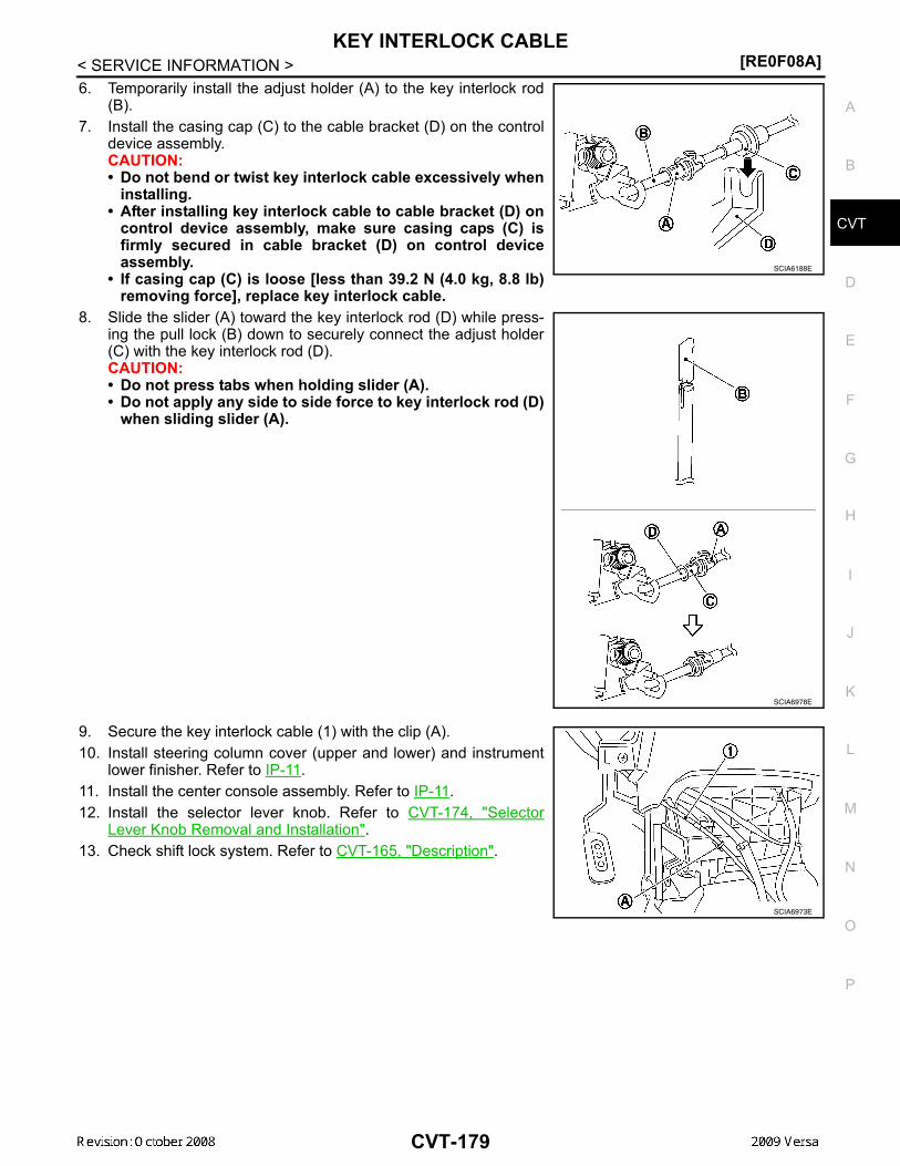
KEY INTERLOCK CABLE[RE0F08A]
D
E
F
G
H
I
J
K
L
M
A
B
VT
N
O
P
< SERVICE INFORMATION >
C
6. Temporarily install the adjust holder (A) to the key interlock rod(B).
7. Install the casing cap (C) to the cable bracket (D) on the controldevice assembly.CAUTION:• Do not bend or twist key interlock cable excessively when
installing.• After installing key interlock cable to cable bracket (D) on
control device assembly, make sure casing caps (C) isfirmly secured in cable bracket (D) on control deviceassembly.
• If casing cap (C) is loose [less than 39.2 N (4.0 kg, 8.8 lb)removing force], replace key interlock cable.
8. Slide the slider (A) toward the key interlock rod (D) while press-ing the pull lock (B) down to securely connect the adjust holder(C) with the key interlock rod (D).CAUTION:• Do not press tabs when holding slider (A).• Do not apply any side to side force to key interlock rod (D)
when sliding slider (A).
9. Secure the key interlock cable (1) with the clip (A).10. Install steering column cover (upper and lower) and instrument
lower finisher. Refer to IP-11.11. Install the center console assembly. Refer to IP-11.12. Install the selector lever knob. Refer to CVT-174, "Selector
Lever Knob Removal and Installation".13. Check shift lock system. Refer to CVT-165, "Description".
SCIA6188E
SCIA6978E
SCIA6973E
CVT-179

[RE0F08A]AIR BREATHER HOSE
< SERVICE INFORMATION >AIR BREATHER HOSERemoval and Installation INFOID:0000000004667114
REMOVAL1. Remove air duct (front), air duct (inlet) and air cleaner case. Refer to EM-139.2. Remove air breather hose.
INSTALLATIONInstallation is in the reverse order of removal.CAUTION:Make sure air breather hose is not collapsed or blocked due to folding or bending when installed.NOTE:• Install the air breather hose (1) to the air breather tube (2) so that
the paint mark (A) faces upward. Also make sure the air breatherhose end is pushed up to the tube bend portion.
• When installing air breather hose (1) to air duct and air cleanercase, make sure to fully insert the hose clips.
1. Air cleaner case 2. Air duct (inlet) 3. Clip4. Air breather hose 5. Air breather tube 6. CVT
WCIA0612E
WCIA0613E
CVT-180

DIFFERENTIAL SIDE OIL SEAL[RE0F08A]
D
E
F
G
H
I
J
K
L
M
A
B
VT
N
O
P
< SERVICE INFORMATION >
C
DIFFERENTIAL SIDE OIL SEALRemoval and Installation INFOID:0000000004667115
COMPONENTS
REMOVAL1. Remove drive shaft assembly. Refer to FAX-9.2. Remove differential side oil seal using a suitable tool.
CAUTION:Do not scratch transaxle case or converter housing.
INSTALLATION1. Drive the new differential side oil seal into the transaxle case
side (B) and converter housing side (C) until it is flush usingTool.
Unit: mm (in)
CAUTION:• Do not reuse differential side oil seals.• Apply specified NISSAN CVT fluid to side oil seals.
2. Install drive shaft assembly. Refer to FAX-9.3. Check CVT fluid level and leakage. Refer to CVT-17, "Checking CVT Fluid".
1. CVT 2. Differential side oil seal : Apply CVT Fluid NS-2.
WCIA0610E
SCIA2412E
Tool number : — (J-47244): ST33400001 (J-47005)
Dimensions (A) 0±0.5 (0±0.020)
WCIA0611E
CVT-181

[RE0F08A]TRANSAXLE ASSEMBLY
< SERVICE INFORMATION >TRANSAXLE ASSEMBLYRemoval and Installation INFOID:0000000004667116
COMPONENTS
REMOVAL1. Remove the engine and transaxle as an assembly. Refer to EM-195, "Removal and Installation".2. Disconnect the secondary speed sensor connector (A) and CVT
unit connector (B). Refer to CVT-13, "Removal and InstallationProcedure for CVT Unit Connector".
3. Remove the harness from the transaxle.
1. CVT fluid level gauge 2. CVT fluid charging pipe 3. O-ring4. Copper washer 5. Fluid cooler tube 6. Transaxle assembly7. Engine mounting bracket (LH) 8. Air breather hose A. Refer to "INSTALLATION".
WCIA0614E
WCIA0615E
CVT-182
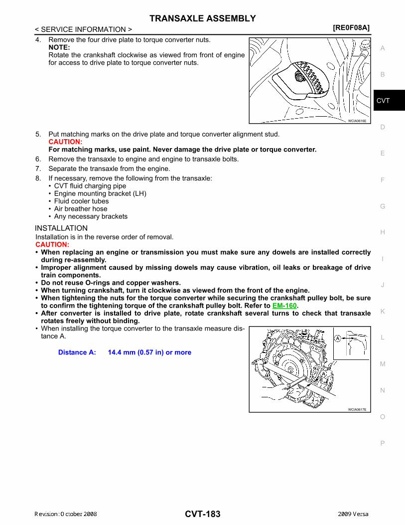
TRANSAXLE ASSEMBLY[RE0F08A]
D
E
F
G
H
I
J
K
L
M
A
B
VT
N
O
P
< SERVICE INFORMATION >
C
4. Remove the four drive plate to torque converter nuts.NOTE:Rotate the crankshaft clockwise as viewed from front of enginefor access to drive plate to torque converter nuts.
5. Put matching marks on the drive plate and torque converter alignment stud.CAUTION:For matching marks, use paint. Never damage the drive plate or torque converter.
6. Remove the transaxle to engine and engine to transaxle bolts.7. Separate the transaxle from the engine.8. If necessary, remove the following from the transaxle:
• CVT fluid charging pipe• Engine mounting bracket (LH)• Fluid cooler tubes• Air breather hose• Any necessary brackets
INSTALLATIONInstallation is in the reverse order of removal.CAUTION:• When replacing an engine or transmission you must make sure any dowels are installed correctly
during re-assembly.• Improper alignment caused by missing dowels may cause vibration, oil leaks or breakage of drive
train components.• Do not reuse O-rings and copper washers.• When turning crankshaft, turn it clockwise as viewed from the front of the engine.• When tightening the nuts for the torque converter while securing the crankshaft pulley bolt, be sure
to confirm the tightening torque of the crankshaft pulley bolt. Refer to EM-160.• After converter is installed to drive plate, rotate crankshaft several turns to check that transaxle
rotates freely without binding.• When installing the torque converter to the transaxle measure dis-
tance A.
WCIA0616E
Distance A: 14.4 mm (0.57 in) or more
WCIA0617E
CVT-183

[RE0F08A]TRANSAXLE ASSEMBLY
< SERVICE INFORMATION >• When installing the cooler outlet tube (1) to the transaxle assembly
(2), align the cooler tube bracket (A) against the transaxle asshown.
• When installing the transaxle to the engine, align the matching mark on the drive plate with the matchingmark on the torque converter alignment stud.
• When securing the transaxle to the engine, attach the bolts inaccordance with the following standard.
• When installing the drive plate to torque converter nuts, tightenthem temporarily. Then tighten the nuts to the specified torque.
• After completing installation check for fluid level, fluid leakage, and the positions of CVT. Refer to CVT-17,"Checking CVT Fluid", CVT-175, "Adjustment of CVT Position" and CVT-175, "Checking of CVT Position".
• When replacing the CVT assembly, erase EEP ROM in TCM. Refer to CVT-12, "Service After ReplacingTCM and Transaxle Assembly".
WCIA0618E
Bolt No. 1 (Transaxle to engine) 2 (Engine to transaxle)
Number of bolts 2 7
Bolt length “A” mm (in) 55 (2.17) 50 (1.97)
Tightening torqueN·m (kg-m, ft-lb) 62 (6.3, 46)
WCIA0619E
Converter nuts: : 51 N·m (5.2 kg-m, 38 ft-lb)
WCIA0616E
CVT-184

SERVICE DATA AND SPECIFICATIONS (SDS)[RE0F08A]
D
E
F
G
H
I
J
K
L
M
A
B
VT
N
O
P
< SERVICE INFORMATION >
C
SERVICE DATA AND SPECIFICATIONS (SDS)General Specification INFOID:0000000004667117
*1: Refer to MA-14, "Fluids and Lubricants" .
Vehicle Speed When Shifting Gears INFOID:0000000004667118
Numerical value data are reference values.
CAUTION:Lock-up clutch is engaged when vehicle speed is approximately 18 km/h (11 MPH) to 90 km/h (56 MPH).
Stall Speed INFOID:0000000004667119
Line Pressure INFOID:0000000004667120
Applied model MR18DE engine
CVT model RE0F08A
CVT assembly Model code number 1XB6B
Transmission gear ratio
“D” position Variable
Reverse 2.689
Final drive 5.473
Recommended fluid NISSAN CVT Fluid NS-2*1
Fluid capacity 8.3 liter (8-3/4 US qt, 7-1/4 Imp qt)
CAUTION:• Use only Genuine NISSAN CVT Fluid NS-2. Do not mix with other fluid.• Using CVT fluid other than Genuine NISSAN CVT Fluid NS-2 will deteriorate in driveability and CVT durability, and may dam-
age the CVT, which is not covered by the warranty.
Engine type Throttle position Shift patternEngine speed (rpm)
At 40 km/h (25 MPH) At 60 km/h (37 MPH)
MR18DE
8/8“D” position
Overdrive-off mode“L” position
3,600 - 4,500 4,400 - 5,300
2/8
“D” position 1,300 - 3,100 1,400 - 3,500
Overdrive-off mode 2,200 - 3,000 2,800 - 3,600
“L” position 3,200 - 4,100 3,900 - 4,800
Stall speed 2,600 - 3,150 rpm
Engine speed Line pressure kPa (kg/cm2 , psi)
“R”, “D” and “L” positions
At idle 650 (6.63, 94.3)
At stall 4,250 (43.35, 616.3)
CVT-185

[RE0F08A]SERVICE DATA AND SPECIFICATIONS (SDS)
< SERVICE INFORMATION >Solenoid Valves INFOID:0000000004667121
CVT Fluid Temperature Sensor INFOID:0000000004667122
Primary Speed Sensor INFOID:0000000004667123
Secondary Speed Sensor INFOID:0000000004667124
Removal and Installation INFOID:0000000004667125
Name Resistance (Approx.) Terminal
Pressure control solenoid valve B (secondary pressure solenoid valve)
3 - 9 Ω
3
Pressure control solenoid valve A (line pressure solenoid valve) 2
Torque converter clutch solenoid valve 12
Lock-up select solenoid valve 6 - 19Ω 13
Name Condition CONSULT-III “DATA MONITOR” (Approx.) Resistance (Approx.)
ATF TEMP SEN20°C (68°F) 2.0 V 6.5 kΩ
80°C (176°F) 1.0 V 0.9 kΩ
Name Condition Data (Approx.)
Primary speed sensor When driving [“L” position, 20 km/h (12 MPH)]. 1000 Hz
Name Condition Data (Approx.)
Secondary speed sensor When driving [“D” position, 20 km/h (12 MPH)]. 570 Hz
Distance between end of converter housing and torque converter 14.4 mm (0.57 in) or more
CVT-186

INDEX FOR DTC[RE0F08B]
D
E
F
G
H
I
J
K
L
M
A
B
VT
N
O
P
< SERVICE INFORMATION >
C
SERVICE INFORMATIONINDEX FOR DTCAlphabetical Index INFOID:0000000004305559
NOTE:If DTC “U1000 CAN COMM CIRCUIT” is displayed with other DTCs, first perform the trouble diagnosisfor “DTC U1000 CAN COMMUNICATION LINE”. Refer to CVT-238.
*1: These numbers are prescribed by SAE J2012.*2: Models without ABS does not indicate.
DTC No. Index INFOID:0000000004305560
NOTE:If DTC “U1000 CAN COMM CIRCUIT” is displayed with other DTCs, first perform the trouble diagnosisfor “DTC U1000 CAN COMMUNICATION LINE”. Refer to CVT-238.
Items(CONSULT-III screen terms)
DTC
Reference pageOBD-II Except OBD-II
CONSULT-III GST*1
CONSULT-III only “TRANSMISSION”
A/T TCC S/V FNCTN P0744 P0744 CVT-271
ATF TEMP SEN/CIRC P0710 P0710 CVT-249
BELT DAMG — P0730 CVT-265
BRAKE SW/CIRC — P0703 CVT-242
CAN COMM CIRCUIT U1000 U1000 CVT-238
CONTROL UNIT(CAN) U1010 U1010 CVT-241
CVT SPD SEN/FNCTN — P1723 CVT-303
ENGINE SPEED SIG — P0725 CVT-263
ELEC TH CONTROL — P1726 CVT-305
ESTM VEH SPD SIG*2 — P1722 CVT-301
INPUT SPD SEN/CIRC P0715 P0715 CVT-254
L/PRESS CONTROL — P1745 CVT-310
L/PRESS SOL/CIRC P0745 P0745 CVT-273
LU-SLCT SOL/CIRC P1740 P1740 CVT-306
PNP SW/CIRC P0705 P0705 CVT-244
PRESS SEN/FNCTN — P0841 CVT-291
PRS CNT SOL/A FCTN P0746 P0746 CVT-278
PRS CNT SOL/B CIRC P0778 P0778 CVT-282
PRS CNT SOL/B FCTN P0776 P0776 CVT-280
SEC/PRESS DOWN — P0868 CVT-293
STEP MOTR CIRC P1777 P1777 CVT-311
STEP MOTR/FNC P1778 P1778 CVT-315
TCC SOLENOID/CIRC P0740 P0740 CVT-266
TCM-POWER SUPPLY — P1701 CVT-295
TP SEN/CIRC A/T — P1705 CVT-299
TR PRS SENS/A CIRC P0840 P0840 CVT-287
VEH SPD SEN/CIR AT P0720 P0720 CVT-258
CVT-187

[RE0F08B]INDEX FOR DTC
< SERVICE INFORMATION >
*1: These numbers are prescribed by SAE J2012.*2: Models without ABS does not indicate.
DTC
Items(CONSULT-III screen terms) Reference page
OBD-II Except OBD-II
CONSULT-IIIGST*1
CONSULT-III only “TRANSMISSION”
— P0703 BRAKE SW/CIRC CVT-242
P0705 P0705 PNP SW/CIRC CVT-244
P0710 P0710 ATF TEMP SEN/CIRC CVT-249
P0715 P0715 INPUT SPD SEN/CIRC CVT-254
P0720 P0720 VEH SPD SEN/CIR AT CVT-258
— P0725 ENGINE SPEED SIG CVT-263
— P0730 BELT DAMG CVT-265
P0740 P0740 TCC SOLENOID/CIRC CVT-266
P0744 P0744 A/T TCC S/V FNCTN CVT-271
P0745 P0745 L/PRESS SOL/CIRC CVT-273
P0746 P0746 PRS CNT SOL/A FCTN CVT-278
P0776 P0776 PRS CNT SOL/B FCTN CVT-280
P0778 P0778 PRS CNT SOL/B CIRC CVT-282
P0840 P0840 TR PRS SENS/A CIRC CVT-287
— P0841 PRESS SEN/FNCTN CVT-291
— P0868 SEC/PRESS DOWN CVT-293
— P1701 TCM-POWER SUPPLY CVT-295
— P1705 TP SEN/CIRC A/T CVT-299
— P1722 ESTM VEH SPD SIG*2 CVT-301
— P1723 CVT SPD SEN/FNCTN CVT-303
— P1726 ELEC TH CONTROL CVT-305
P1740 P1740 LU-SLCT SOL/CIRC CVT-306
— P1745 L/PRESS CONTROL CVT-310
P1777 P1777 STEP MOTR CIRC CVT-311
P1778 P1778 STEP MOTR/FNC CVT-315
U1000 U1000 CAN COMM CIRCUIT CVT-238
U1010 U1010 CONTROL UNIT(CAN) CVT-241
CVT-188
PRECAUTIONS[RE0F08B]
D
E
F
G
H
I
J
K
L
M
A
B
VT
N
O
P
< SERVICE INFORMATION >
C
PRECAUTIONSPrecaution for Supplemental Restraint System (SRS) "AIR BAG" and "SEAT BELT PRE-TENSIONER" INFOID:0000000004800720
The Supplemental Restraint System such as “AIR BAG” and “SEAT BELT PRE-TENSIONER”, used alongwith a front seat belt, helps to reduce the risk or severity of injury to the driver and front passenger for certaintypes of collision. This system includes seat belt switch inputs and dual stage front air bag modules. The SRSsystem uses the seat belt switches to determine the front air bag deployment, and may only deploy one frontair bag, depending on the severity of a collision and whether the front occupants are belted or unbelted.Information necessary to service the system safely is included in the SRS and SB section of this Service Man-ual.WARNING:• To avoid rendering the SRS inoperative, which could increase the risk of personal injury or death in
the event of a collision which would result in air bag inflation, all maintenance must be performed byan authorized NISSAN/INFINITI dealer.
• Improper maintenance, including incorrect removal and installation of the SRS can lead to personalinjury caused by unintentional activation of the system. For removal of Spiral Cable and Air BagModule, see the SRS section.
• Do not use electrical test equipment on any circuit related to the SRS unless instructed to in thisService Manual. SRS wiring harnesses can be identified by yellow and/or orange harnesses or har-ness connectors.
• When working near the Airbag Diagnosis Sensor Unit or other Airbag System sensors with the Igni-tion ON or engine running, DO NOT use air or electric power tools or strike near the sensor(s) with ahammer. Heavy vibration could activate the sensor(s) and deploy the air bag(s), possibly causingserious injury.
• When using air or electric power tools or hammers, always switch the Ignition OFF, disconnect thebattery, and wait at least 3 minutes before performing any service.
Precaution Necessary for Steering Wheel Rotation After Battery DisconnectINFOID:0000000004305562
NOTE:• This Procedure is applied only to models with Intelligent Key system and NVIS/IVIS (NISSAN/INFINITI
VEHICLE IMMOBILIZER SYSTEM - NATS).• Remove and install all control units after disconnecting both battery cables with the ignition knob in the″LOCK″ position.
• Always use CONSULT-III to perform self-diagnosis as a part of each function inspection after finishing work.If DTC is detected, perform trouble diagnosis according to self-diagnostic results.
For models equipped with the Intelligent Key system and NVIS/IVIS, an electrically controlled steering lockmechanism is adopted on the key cylinder.For this reason, if the battery is disconnected or if the battery is discharged, the steering wheel will lock andsteering wheel rotation will become impossible.If steering wheel rotation is required when battery power is interrupted, follow the procedure below beforestarting the repair operation.
OPERATION PROCEDURE1. Connect both battery cables.
NOTE:Supply power using jumper cables if battery is discharged.
2. Use the Intelligent Key or mechanical key to turn the ignition switch to the ″ACC″ position. At this time, thesteering lock will be released.
3. Disconnect both battery cables. The steering lock will remain released and the steering wheel can berotated.
4. Perform the necessary repair operation.5. When the repair work is completed, return the ignition switch to the ″LOCK″ position before connecting
the battery cables. (At this time, the steering lock mechanism will engage.)6. Perform a self-diagnosis check of all control units using CONSULT-III.
CVT-189

[RE0F08B]PRECAUTIONS
< SERVICE INFORMATION >Precaution for On Board Diagnosis (OBD) System of CVT and Engine INFOID:0000000004305563
The ECM has an on board diagnostic system. It will light up the malfunction indicator lamp (MIL) to warn thedriver of a malfunction causing emission deterioration.CAUTION:• Be sure to turn the ignition switch OFF and disconnect the battery cable from the negative terminal
before any repair or inspection work. The open/short circuit of related switches, sensors, solenoidvalves, etc. will cause the MIL to light up.
• Be sure to connect and lock the connectors securely after work. A loose (unlocked) connector willcause the MIL to light up due to an open circuit. (Be sure the connector is free from water, grease,dirt, bent terminals, etc.)
• Be sure to route and secure the harnesses properly after work. Interference of the harness with abracket, etc. may cause the MIL to light up due to a short circuit.
• Be sure to connect rubber tubes properly after work. A misconnected or disconnected rubber tubemay cause the MIL to light up due to a malfunction of the EVAP system or fuel injection system, etc.
• Be sure to erase the unnecessary malfunction information (repairs completed) from the TCM andECM before returning the vehicle to the customer.
Service After Replacing TCM and Transaxle Assembly INFOID:0000000004305564
SERVICE AFTER REPLACING TCM AND TRANSAXLE ASSEMBLYPerform the applicable service according to the following table when replacing TCM or transaxle assembly.CAUTION:• Never start the engine until the service is completed.• “DTC P1701” may be indicated soon after replacing TCM or transaxle assembly (after erasing the
memory in the pattern B). Restart the self-diagnosis after erasing the self-diagnosis result usingCONSULT-III. Check that no error is detected.
NOTE:Old unit means that the unit has been already used for another vehicle.
PATTERN A1. Shift the selector lever to “P” position after replacing TCM.2. Turn ignition switch ON.3. Check that the shift position indicator in the combination meter turns ON (It indicates approximately 1 or 2
seconds after turning ignition switch ON.)• Check the following items if shift position indicator does not turn ON. Repair or replace accordingly as
necessary.- The harness between TCM and ROM ASSY in transaxle assembly is open or shorted.- Terminals disconnected, loose, or bent from connector housing.
PATTERN B1. Turn ignition switch ON after replacing each part.2. Connect the vehicle with CONSULT-III.3. Start engine.
CAUTION:Never start driving.
4. Select “Data monitor” in “TRANSMISSION”.5. Warm up transaxle assembly until “ATFTEMP COUNT” indicates 47 [approximately 20°C (68°F)] or more,
and then turn ignition switch OFF.6. Turn ignition switch ON.
TCM Transaxle assembly Service pattern
Replaced with new unit Not replaced the unit “PATTERN A”
Not replaced the unit Replaced with new or old unit
“PATTERN B”Replaced with old unit
Not replaced the unit
Replaced with new or old unit
Replaced with new unit Replaced with new or old unit “PATTERN C”
CVT-190
PRECAUTIONS[RE0F08B]
D
E
F
G
H
I
J
K
L
M
A
B
VT
N
O
P
< SERVICE INFORMATION >
C
CAUTION:Never start engine.
7. Select “Self Diagnostic Results” in “TRANSMISSION”.8. Shift the selector lever to “R” position.9. Depress slightly the accelerator pedal (Pedal angle: 2/8) while depressing the brake pedal. 10. Select “Erase”.11. Turn ignition switch OFF while keeping the selector lever in “R” position.12. Wait approximately 10 seconds.13. Turn ignition switch ON while keeping the selector lever in “R” position.
CAUTION:Never start engine.
14. Select “Special function” in “TRANSMISSION”.15. Check that the value on “CALIBRATION DATA” in CONSULT-III is the same as the data listed in the table
below.• Restart the procedure from step 3 if the values are not the same.CALIBRATION DATA
16. Shift the selector lever to “P” position.17. Check that the shift position indicator in combination meter turns ON. (It indicates approximately 1 or 2
seconds after shifting the selector lever to “P” position.)• Check the following items if shift position indicator does not turn ON. Repair or replace accordingly as
necessary.- The harness between TCM and ROM ASSY in transaxle assembly is open or shorted.- Terminals disconnected, loose, or bent from connector housing.- Power supply and ground of TCM. Refer to CVT-295, "Description".
PATTERN C1. Replace transaxle assembly first, and then replace TCM.2. Perform the service of “PATTERN A”.
(Perform the service of “PATTERN B” if TCM is replaced first.)
Removal and Installation Procedure for CVT Unit Connector INFOID:0000000004305565
REMOVAL
Item name Display value Item name Display value
UNIT CLB ID 1 00 GAIN PL 256
UNIT CLB ID 2 00 OFFSET PL 40
UNIT CLB ID 3 00 OFFSET2 PL 0
UNIT CLB ID 4 00 MAP NO SEC 32
UNIT CLB ID 5 00 GAIN SEC 256
UNIT CLB ID 6 00 OFFSET SEC 40
MAP NO LU 33 OFFSET2 SEC 0
GAIN LU 256 MAP NO SL 32
OFFSET LU 40 GAIN SL 256
OFFSET2 LU 0 OFFSET SL 40
MAP NO PL 32 OFFSET2 SL 0
CVT-191

[RE0F08B]PRECAUTIONS
< SERVICE INFORMATION >Rotate bayonet ring counterclockwise, pull out CVT unit harnessconnector upward and disconnect it.
INSTALLATION1. Align CVT unit harness connector terminal body marking with
bayonet ring marking, insert CVT unit harness connector, andthen rotate bayonet ring clockwise.
2. Rotate bayonet ring clockwise until CVT unit harness connectorterminal body marking is aligned with the bayonet ring marking(linear slit) as shown.
CAUTION:• Securely align CVT unit harness connector terminal body
marking with bayonet ring marking (linear slit). Do notmake a half fit condition as shown.
• Do not mistake the bayonet ring marking (linear slit) forother dent portion.
Precaution INFOID:0000000004305566
NOTE:If any malfunction occurs in the RE0F08B model transaxle, replace the entire transaxle assembly.
SCIA2096E
SCIA2097E
SCIA2098E
SCIA2099E
CVT-192

PRECAUTIONS[RE0F08B]
D
E
F
G
H
I
J
K
L
M
A
B
VT
N
O
P
< SERVICE INFORMATION >
C
• Before connecting or disconnecting the TCM harness connec-tor, turn ignition switch OFF and disconnect negative batterycable. Because battery voltage is applied to TCM even if igni-tion switch is turned OFF.
• When connecting or disconnecting pin connectors into orfrom TCM, take care not to damage pin terminals (bend orbreak).When connecting pin connectors make sure that there are notany bends or breaks on TCM pin terminal.
• Before replacing TCM, perform TCM input/output signalinspection and make sure whether TCM functions properly ornot. CVT-228, "TCM Terminal and Reference Value".
• After performing each TROUBLE DIAGNOSIS, perform “DTCConfirmation Procedure”.If the repair is completed the DTC should not be displayed inthe “DTC Confirmation Procedure”.
• Always use the specified brand of CVT fluid. Refer to MA-14, "Flu-ids and Lubricants".
• Use lint-free paper, not cloth rags, during work.• After replacing the CVT fluid, dispose of the waste oil using the
methods prescribed by law, ordinance, etc.
Service Notice or Precaution INFOID:0000000004305567
CVT FLUID COOLER SERVICEIf CVT fluid contains friction material (clutches, brakes, etc.), or if an CVT is replaced, inspect and clean theCVT fluid cooler mounted in the radiator or replace the radiator. Flush cooler lines using cleaning solvent andcompressed air after repair. For CVT fluid cooler cleaning procedure, refer to CVT-197, "CVT Fluid CoolerCleaning". For radiator replacement, refer to CO-38.
OBD-II SELF-DIAGNOSIS
SEF289H
SEF291H
MEF040DA
SEF217U
CVT-193

[RE0F08B]PRECAUTIONS
< SERVICE INFORMATION >• CVT self-diagnosis is performed by the TCM in combination with the ECM. The results can be read through
the blinking pattern of the malfunction indicator lamp (MIL). Refer to the table on CVT-230, "CONSULT-IIIFunction (TRANSMISSION)" for the indicator used to display each self-diagnostic result.
• The self-diagnostic results indicated by the MIL are automatically stored in both the ECM and TCM memo-ries.Always perform the procedure on CVT-209, "OBD-II Diagnostic Trouble Code (DTC)" to complete therepair and avoid unnecessary blinking of the MIL.
For details of OBD-II, refer to EC-1051, "Introduction".• Certain systems and components, especially those related to OBD, may use the new style slide-lock-
ing type harness connector. For description and how to disconnect, refer to PG-64.
CVT-194

PREPARATION[RE0F08B]
D
E
F
G
H
I
J
K
L
M
A
B
VT
N
O
P
< SERVICE INFORMATION >
C
PREPARATIONSpecial Service Tool INFOID:0000000004305568
The actual shapes of Kent-Moore tools may differ from those of special service tools illustrated here.
Commercial Service Tool INFOID:0000000004305569
Tool number(Kent-Moore No.)Tool name
Description
—(OTC3492)Oil pressure gauge set
Measuring line pressure
—(J-47244)Drift
Installing differential side oil seal• Transaxle case side (left)a: 65.83 mm (2.59 in) dia.b: 53.85 mm (2.12 in) dia.
ST33400001(J-47005)Drift
Installing differential side oil seal• Converter housing side (right)a: 69.85 mm (2.75 in) dia.b: 49.53 mm (1.95 in) dia.
SCIA7531E
SCIA5777E
SCIA5777E
Tool numberTool name Description
Power tool Loosening nuts and bolts
PBIC0190E
CVT-195

[RE0F08B]CVT FLUID
< SERVICE INFORMATION >CVT FLUIDChecking CVT Fluid INFOID:0000000004305570
FLUID LEVEL CHECKFluid level should be checked with the fluid warmed up to 50° to 80°C (122° to 176°F).1. Check for fluid leakage.2. With the engine warmed up, drive the vehicle to warm up the
CVT fluid. When ambient temperature is 20°C (68°F), it takesabout 10 minutes for the CVT fluid to warm up to 50° to 80°C(122° to 176°F).
3. Park the vehicle on a level surface and set the parking brake.4. With engine at idle, while depressing brake pedal, move the
selector lever throughout the entire shift range and return it tothe “P” position.
5. Press the tab on the CVT fluid level gauge to release the lockand pull out the CVT fluid level gauge from the CVT fluid charg-ing pipe.
6. Wipe fluid off the CVT fluid level gauge. Then rotate the CVTfluid level gauge 180° and re-insert it into the CVT charging pipeas far as it will go.CAUTION:Always use lint free paper towels to wipe fluid off the CVTfluid level gauge.
7. Remove the CVT fluid level gauge and check that the fluid levelis within the specified range as shown. If the fluid level is at orbelow the low side of the range, add the necessary specifiedNISSAN CVT fluid through the CVT charging pipe.
CAUTION:• Only use specified NISSAN CVT fluid.• Do not overfill the CVT.
8. Install the CVT fluid level gauge to the CVT fluid charging pipe until it locks.CAUTION:When CVT fluid level gauge is installed into the CVT fluid charging pipe, make sure that the CVTfluid level gauge is securely locked in place.
SMA146B
SCIA1933E
SCIA1931E
Fluid grade: Refer to MA-14, "Fluids and Lubri-cants".
SCIA1932E
CVT-196

CVT FLUID[RE0F08B]
D
E
F
G
H
I
J
K
L
M
A
B
VT
N
O
P
< SERVICE INFORMATION >
C
FLUID CONDITION CHECK
Changing CVT Fluid INFOID:0000000004305571
1. Warm up CVT fluid by driving the vehicle for 10 minutes.• : Vehicle front• Radiator (2)• CVT fluid cooler hose [inlet side (3)]• Transaxle assembly (4)2. Drain CVT fluid from CVT fluid cooler hose [outlet side (1)] and
refill with new specified NISSAN CVT fluid in the CVT fluidcharging pipe with the engine running at idle speed.
CAUTION:Only use the specified NISSAN CVT fluid.
3. Refill until new CVT fluid comes out from CVT fluid cooler hose [outlet side (1)].NOTE:About 30 to 50% extra fluid will be required for this procedure.
4. Check fluid level and condition. Refer to CVT-196, "Checking CVT Fluid".CAUTION:Delete CVT fluid deterioration date with CONSULT-III after changing CVT fluid. Refer to CVT-230,"CONSULT-III Function (TRANSMISSION)".
CVT Fluid Cooler Cleaning INFOID:0000000004305572
Whenever a CVT is repaired, overhauled, or replaced, the CVT fluid cooler mounted in the radiator must beinspected and cleaned.Metal debris and friction material, if present, can be trapped or become deposit in the CVT fluid cooler. Thisdebris can contaminate the newly serviced CVT or, in severe cases, can block or restrict the flow of CVT fluid.In either case, malfunction of the newly serviced CVT may occur.Debris, if present, may deposit as CVT fluid enters the cooler inlet. It will be necessary to back flush the coolerthrough the cooler outlet in order to flush out any built up debris.
CVT FLUID COOLER CLEANING PROCEDURE1. Identify the CVT inlet and outlet fluid cooler hoses.2. Position an oil pan under the inlet and outlet cooler hoses.
Fluid status Conceivable cause Required operation
Varnished (viscous varnish state)
Clutch, brake scorched
Replace the CVT fluid and check the CVT main unit and the vehicle for malfunctions (wire harness, cooler pipes, etc.)
Milky white or cloudy Water in the fluid Replace the CVT fluid and check for places where water is getting in.
Large amount of metal powder mixed in fluid
Unusual wear of sliding parts within CVT
Replace the CVT fluid and check for improper operation of the CVT.
ATA0022D
Fluid capacity and grade: Refer to MA-14, "Fluids and Lubricants".
SCIA6088E
CVT-197

[RE0F08B]CVT FLUID
< SERVICE INFORMATION >3. Disconnect the fluid cooler inlet and outlet rubber hoses from the
steel cooler tubes.NOTE:Replace the cooler hoses if rubber material from the hoseremains on the tube fitting.
4. Allow any CVT fluid that remains in the cooler hoses to drain intothe oil pan.
5. Insert the extension adapter hose of a can of TransmissionCooler Cleaner (Nissan P/N 999MP-AM006) into the cooler out-let hose.CAUTION:• Wear safety glasses and rubber gloves when spraying the
Transmission Cooler Cleaner.• Spray Transmission Cooler Cleaner only with adequate
ventilation.• Avoid contact with eyes and skin.• Do not breath vapors or spray mist.
6. Hold the hose and can as high as possible and spray Transmis-sion Cooler Cleaner in a continuous stream into the cooler outlethose until CVT fluid flows out of the cooler inlet hose for 5 seconds.
7. Insert the tip of an air gun into the end of the cooler outlet hose.8. Wrap a shop rag around the air gun tip and of the cooler outlet
hose.9. Blow compressed air regulated to 5 to 9 kg/cm2 (71 to 128 psi)
through the cooler outlet hose for 10 seconds to force out anyremaining CVT fluid.
10. Repeat steps 5 through 9 three additional times.11. Position an oil pan under the banjo bolts that connect the CVT
fluid cooler steel lines to the transaxle.12. Remove the banjo bolts.13. Flush each steel line from the cooler side back toward the tran-
saxle by spraying Transmission Cooler Cleaner in a continuous stream for 5 seconds.14. Blow compressed air regulated to 5 to 9 kg/cm2 (71 to 128 psi) through each steel line from the cooler
side back toward the transaxle for 10 seconds to force out any remaining CVT fluid.15. Ensure all debris is removed from the steel cooler lines.16. Ensure all debris is removed from the banjo bolts and fittings.17. Perform "CVT FLUID COOLER DIAGNOSIS PROCEDURE".
CVT FLUID COOLER DIAGNOSIS PROCEDURENOTE:Insufficient cleaning of the cooler inlet hose exterior may lead to inaccurate debris identification.1. Position an oil pan under the transaxle's inlet and outlet cooler hoses.2. Clean the exterior and tip of the cooler inlet hose.
SCIA4421E
SCIA4422E
SCIA4423E
CVT-198

CVT FLUID[RE0F08B]
D
E
F
G
H
I
J
K
L
M
A
B
VT
N
O
P
< SERVICE INFORMATION >
C
3. Insert the extension adapter hose of a can of TransmissionCooler Cleaner (Nissan P/N 999MP-AM006) into the cooler out-let hose.CAUTION:• Wear safety glasses and rubber gloves when spraying the
Transmission Cooler Cleaner.• Spray Transmission Cooler Cleaner only with adequate
ventilation.• Avoid contact with eyes and skin.• Do not breath vapors or spray mist.
4. Hold the hose and can as high as possible and spray Transmis-sion Cooler Cleaner in a continuous stream into the cooler outlethose until CVT fluid flows out of the cooler inlet hose for 5 seconds.
5. Tie a common white, basket-type coffee filter to the end of thecooler inlet hose.
6. Insert the tip of an air gun into the end of the cooler outlet hose.7. Wrap a shop rag around the air gun tip and end of cooler outlet
hose.8. Blow compressed air regulated to 5 to 9 kg/cm2 (71 to 128 psi)
through the cooler outlet hose to force any remaining CVT fluidinto the coffee filter.
9. Remove the coffee filter from the end of the cooler inlet hose.10. Perform "CVT FLUID COOLER INSPECTION PROCEDURE".
CVT FLUID COOLER INSPECTION PROCEDURE1. Inspect the coffee filter for debris.a. If small metal debris less than 1 mm (0.040 in) in size or metal
powder is found in the coffee filter, this is normal. If normaldebris is found, the CVT fluid cooler/radiator can be re-used andthe procedure is ended.
SCIA4421E
SCIA4424E
SCIA4425E
SCIA2967E
CVT-199

[RE0F08B]CVT FLUID
< SERVICE INFORMATION >b. If one or more pieces of debris are found that are over 1 mm
(0.040 in) in size and/or peeled clutch facing material is found inthe coffee filter, the fluid cooler is not serviceable. The radiator/fluid cooler must be replaced and the inspection procedure isended.
CVT FLUID COOLER FINAL INSPECTIONAfter performing all procedures, ensure that all remaining oil is cleaned from all components.
SCIA7031E
CVT-200
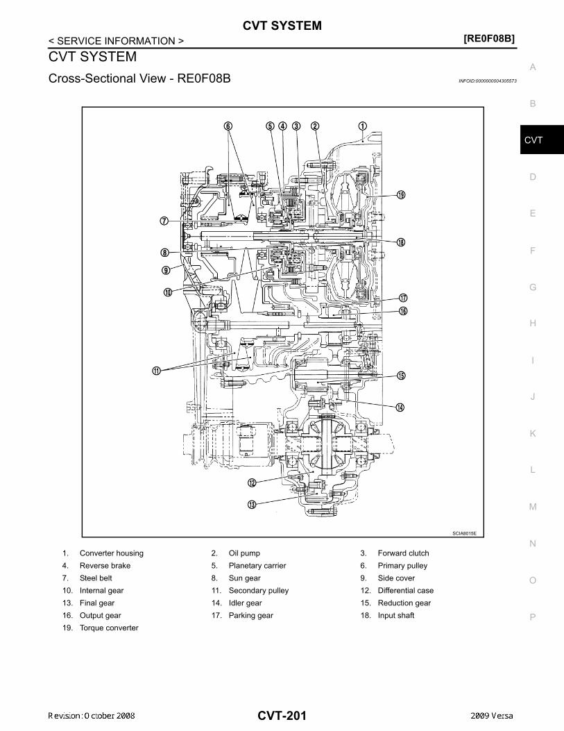
CVT SYSTEM[RE0F08B]
D
E
F
G
H
I
J
K
L
M
A
B
VT
N
O
P
< SERVICE INFORMATION >
C
CVT SYSTEMCross-Sectional View - RE0F08B INFOID:0000000004305573
1. Converter housing 2. Oil pump 3. Forward clutch4. Reverse brake 5. Planetary carrier 6. Primary pulley7. Steel belt 8. Sun gear 9. Side cover10. Internal gear 11. Secondary pulley 12. Differential case13. Final gear 14. Idler gear 15. Reduction gear16. Output gear 17. Parking gear 18. Input shaft19. Torque converter
SCIA8015E
CVT-201

[RE0F08B]CVT SYSTEM
< SERVICE INFORMATION >Control System INFOID:0000000004305574
AWDIA0645GB
CVT-202

CVT SYSTEM[RE0F08B]
D
E
F
G
H
I
J
K
L
M
A
B
VT
N
O
P
< SERVICE INFORMATION >
C
Hydraulic Control System INFOID:0000000004305575
TCM Function INFOID:0000000004305576
The function of the TCM is to:• Receive input signals sent from various switches and sensors.• Determine required line pressure, shifting point, and lock-up operation.• Send required output signals to the step motor and the respective solenoids.
CONTROL SYSTEM OUTLINE The CVT senses vehicle operating conditions through various sensors. It always controls the optimum shiftposition and reduces shifting and lock-up shocks.
SCIA1807E
SENSORS (or SIGNAL)
⇒
TCM
⇒
ACTUATORS
PNP switchAccelerator pedal position signalClosed throttle position signalEngine speed signalCVT fluid temperature sensorVehicle speed signalOverdrive control signalStop lamp switch signalPrimary speed sensorSecondary speed sensorSecondary pressure sensor
Shift controlLine pressure controlPrimary pressure controlSecondary pressure controlLock-up controlEngine brake controlVehicle speed controlFail-safe controlSelf-diagnosisCONSULT-III communication lineDuet-EA controlCAN systemOn board diagnosis
Step motor Torque converter clutch solenoid valveLock-up select solenoid valveLine pressure solenoid valveSecondary pressure solenoid valveShift position indicatorO/D OFF indicator lampStarter relay
CVT-203
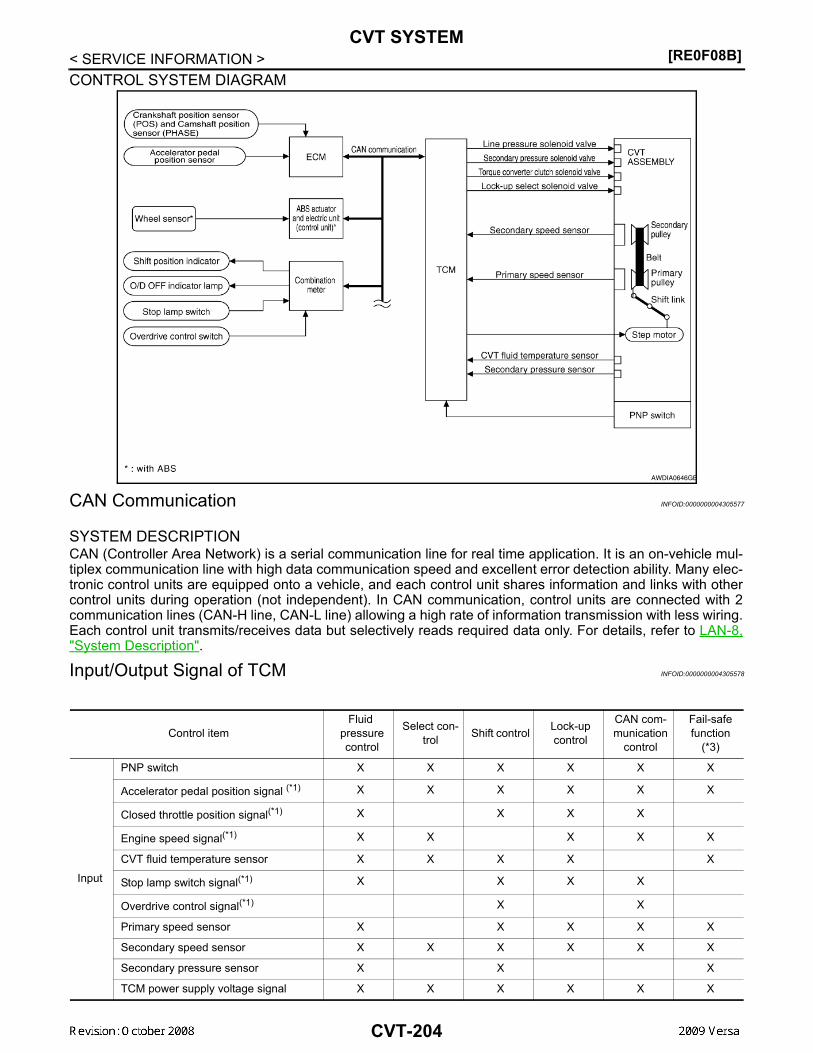
[RE0F08B]CVT SYSTEM
< SERVICE INFORMATION >CONTROL SYSTEM DIAGRAM
CAN Communication INFOID:0000000004305577
SYSTEM DESCRIPTION CAN (Controller Area Network) is a serial communication line for real time application. It is an on-vehicle mul-tiplex communication line with high data communication speed and excellent error detection ability. Many elec-tronic control units are equipped onto a vehicle, and each control unit shares information and links with othercontrol units during operation (not independent). In CAN communication, control units are connected with 2communication lines (CAN-H line, CAN-L line) allowing a high rate of information transmission with less wiring.Each control unit transmits/receives data but selectively reads required data only. For details, refer to LAN-8,"System Description".
Input/Output Signal of TCM INFOID:0000000004305578
AWDIA0646GB
Control itemFluid
pressure control
Select con-trol Shift control Lock-up
control
CAN com-munication
control
Fail-safe function
(*3)
Input
PNP switch X X X X X X
Accelerator pedal position signal (*1) X X X X X X
Closed throttle position signal(*1) X X X X
Engine speed signal(*1) X X X X X
CVT fluid temperature sensor X X X X X
Stop lamp switch signal(*1) X X X X
Overdrive control signal(*1) X X
Primary speed sensor X X X X X
Secondary speed sensor X X X X X X
Secondary pressure sensor X X X
TCM power supply voltage signal X X X X X X
CVT-204

CVT SYSTEM[RE0F08B]
D
E
F
G
H
I
J
K
L
M
A
B
VT
N
O
P
< SERVICE INFORMATION >
C
*1: Input by CAN communications.*2: Output by CAN communications.*3: If these input and output signals are different, the TCM triggers the fail-safe function.
Line Pressure and Secondary Pressure Control INFOID:0000000004305579
• When an input torque signal equivalent to the engine drive force is sent from the ECM to the TCM, the TCMcontrols the line pressure solenoid valve and secondary pressure solenoid valve.
• This line pressure solenoid controls the pressure regulator valve as the signal pressure and adjusts the pres-sure of the operating oil discharged from the oil pump to the line pressure most appropriate to the drivingstate. Secondary pressure is controlled by decreasing line pressure.
NORMAL CONTROLOptimize the line pressure and secondary pressure, depending on driving conditions, on the basis of the throt-tle position, the engine speed, the primary pulley (input) revolution speed, the secondary pulley (output) revo-lution speed, the brake signal, the PNP switch signal, the lock-up signal, the voltage, the target gear ratio, thefluid temperature, and the fluid pressure.
FEEDBACK CONTROLWhen controlling the normal fluid pressure or the selected fluid pressure, the secondary pressure can be setmore accurately by using the fluid pressure sensor to detect the secondary pressure and controlling the feed-back.
Shift Control INFOID:0000000004305580
In order to select the gear ratio which can obtain the driving force in accordance with driver's intention and thevehicle condition, TCM monitors the driving conditions, such as the vehicle speed and the throttle position andselects the optimum gear ratio, and determines the gear change steps to the gear ratio. Then send the com-
Out-put
Step motor X X
TCC solenoid valve X X X
Lock-up select solenoid valve X X X
Line pressure solenoid valve X X X X
Secondary pressure solenoid valve X X X
O/D OFF indicator signal(*2) X X
Control itemFluid
pressure control
Select con-trol Shift control Lock-up
control
CAN com-munication
control
Fail-safe function
(*3)
SCIA1846E
CVT-205

[RE0F08B]CVT SYSTEM
< SERVICE INFORMATION >mand to the step motor, and control the flow-in/flow-out of line pressure from the primary pulley to determinethe position of the moving-pulley and control the gear ratio.
NOTE:The gear ratio is set for every position separately.
“D” POSITIONShifting over all the ranges of gear ratios from the lowest to the high-est.
OVERDRIVE-OFF MODEUse this position for the improved engine braking.
“L” POSITIONBy limiting the gear range to the lowest position, the strong drivingforce and the engine brake can be secured.
DOWNHILL ENGINE BRAKE CONTROL (AUTO ENGINE BRAKE CONTROL)When downhill is detected with the accelerator pedal released, the engine brake will be strengthened up bydownshifting so as not to accelerate the vehicle more than necessary.
ACCELERATION CONTROLAccording to vehicle speed and a change of accelerator pedal angle, driver's request for acceleration and driv-ing scene are judged. This function assists improvement in acceleration feeling by making the engine speedproportionate to the vehicle speed. And a shift map which can gain a larger driving force is available for com-patibility of mileage with driveability.
SCIA7958E
SCIA1953E
SCIA1955E
CVT-206

CVT SYSTEM[RE0F08B]
D
E
F
G
H
I
J
K
L
M
A
B
VT
N
O
P
< SERVICE INFORMATION >
C
Lock-up and Select Control INFOID:0000000004305581
• The torque converter clutch piston in the torque converter is engaged to eliminate torque converter slip toincrease power transmission efficiency.
• The torque converter clutch control valve operation is controlled by the torque converter clutch solenoidvalve, which is controlled by a signal from TCM. The torque converter clutch control valve engages orreleases the torque converter clutch piston.
• When shifting between “N” (“P”) ⇔ “D” (“R”), torque converter clutch solenoid controls engagement power offorward clutch and reverse brake.
• The lock-up applied gear range was expanded by locking up thetorque converter at a lower vehicle speed than conventional CVTmodels.
TORQUE CONVERTER CLUTCH AND SELECT CONTROL VALVE CONTROL Lock-up and Select Control System Diagram
Lock-up Released In the lock-up released state, the torque converter clutch control valve is set into the unlocked state by thetorque converter clutch solenoid and the lock-up apply pressure is drained.In this way, the torque converter clutch piston is not coupled.Lock-up AppliedIn the lock-up applied state, the torque converter clutch control valve is set into the locked state by the torqueconverter clutch solenoid and lock-up apply pressure is generated.In this way, the torque converter clutch piston is pressed and coupled.Select ControlWhen shifting between “N” (“P”)⇔“D” (“R”), optimize the operating pressure on the basis of the throttle posi-tion, the engine speed, and the secondary pulley (output) revolution speed to lessen the shift shock.
Control Valve INFOID:0000000004305582
FUNCTION OF CONTROL VALVE
SCIA1958E
SCIA2374E
CVT-207

[RE0F08B]CVT SYSTEM
< SERVICE INFORMATION >Name Function
Torque converter regulator valve Optimizes the supply pressure for the torque converter depending on driving conditions.
Pressure regulator valve Optimizes the discharge pressure from the oil pump depending on driving conditions.
TCC control valve • Activates or deactivate the lock-up.• Lock-up smoothly by opening lock-up operation excessively.
TCC solenoid valve Controls the TCC control valve or select control valve.
Shift control valve Controls flow-in/out of line pressure from the primary pulley depending on the stroke dif-ference between the stepping motor and the primary pulley.
Secondary valve Controls the line pressure from the secondary pulley depending on operating conditions.
Clutch regulator valve Adjusts the clutch operating pressure depending on operating conditions.
Secondary pressure solenoid valve Controls the secondary valve.
Line pressure solenoid valve Controls the line pressure control valve.
Step motor Controls the pulley ratio.
Manual valve Transmits the clutch operating pressure to each circuit in accordance with the selected position.
Select control valve Engages forward clutch, reverse brake smoothly depending on select operation.
Select switch valve Switches torque converter clutch solenoid valve control pressure use to torque converter clutch control valve or select control valve.
Lock-up select solenoid valve Controls the select switch valve.
CVT-208

ON BOARD DIAGNOSTIC (OBD) SYSTEM[RE0F08B]
D
E
F
G
H
I
J
K
L
M
A
B
VT
N
O
P
< SERVICE INFORMATION >
C
ON BOARD DIAGNOSTIC (OBD) SYSTEMIntroduction INFOID:0000000004305583
The CVT system has two self-diagnostic systems.The first is the emission-related on board diagnostic system (OBD-II) performed by the TCM in combinationwith the ECM. The malfunction is indicated by the MIL (malfunction indicator lamp) and is stored as a DTC inthe ECM memory, and the TCM memory.The second is the TCM original self-diagnosis performed by the TCM. The malfunction is stored in the TCMmemory. The detected items are overlapped with OBD-II self-diagnostic items. For detail, refer to CVT-230,"CONSULT-III Function (TRANSMISSION)".
OBD-II Function for CVT System INFOID:0000000004305584
The ECM provides emission-related on board diagnostic (OBD-II) functions for the CVT system. One functionis to receive a signal from the TCM used with OBD-related parts of the CVT system. The signal is sent to theECM when a malfunction occurs in the corresponding OBD-related part. The other function is to indicate adiagnostic result by means of the MIL (malfunction indicator lamp) on the instrument panel. Sensors, switchesand solenoid valves are used as sensing elements.The MIL automatically illuminates in One or Two Trip Detection Logic when a malfunction is sensed in relationto CVT system parts.
One or Two Trip Detection Logic of OBD-II INFOID:0000000004305585
ONE TRIP DETECTION LOGICIf a malfunction is sensed during the first test drive, the MIL will illuminate and the malfunction will be stored inthe ECM memory as a DTC. The TCM is not provided with such a memory function.
TWO TRIP DETECTION LOGICWhen a malfunction is sensed during the first test drive, it is stored in the ECM memory as a 1st trip DTC(diagnostic trouble code) or 1st trip freeze frame data. At this point, the MIL will not illuminate. — 1st tripIf the same malfunction as that experienced during the first test drive is sensed during the second test drive,the MIL will illuminate. — 2nd tripThe “trip” in the “One or Two Trip Detection Logic” means a driving mode in which self-diagnosis is performedduring vehicle operation.
OBD-II Diagnostic Trouble Code (DTC) INFOID:0000000004305586
HOW TO READ DTC AND 1ST TRIP DTCDTC and 1st trip DTC can be read by the following methods.( with CONSULT-III or GST) CONSULT-III or GST (Generic Scan Tool) Examples: P0705, P0720 etc.These DTC are prescribed by SAE J2012.(CONSULT-III also displays the malfunctioning component or system.)• 1st trip DTC No. is the same as DTC No.• Output of the diagnostic trouble code indicates that the indicated circuit has a malfunction. How-
ever, in case of the Mode II and GST, they do not indicate whether the malfunction is still occurring oroccurred in the past and returned to normal.CONSULT-III can identify them as shown below, therefore, CONSULT-III (if available) is recom-mended.
DTC or 1st trip DTC of a malfunction is displayed in SELF-DIAGNOSTIC RESULTS mode for “ENGINE” withCONSULT-III. Time data indicates how many times the vehicle was driven after the last detection of a DTC.
If the DTC is being detected currently, the time data will be “0”.
If a 1st trip DTC is stored in the ECM, the time data will be “1t”.
Freeze Frame Data and 1st Trip Freeze Frame Data
CVT-209

[RE0F08B]ON BOARD DIAGNOSTIC (OBD) SYSTEM
< SERVICE INFORMATION >The ECM has a memory function, which stores the driving condition such as fuel system status, calculatedload value, engine coolant temperature, short term fuel trim, long term fuel trim, engine speed and vehiclespeed at the moment the ECM detects a malfunction.Data which are stored in the ECM memory, along with the 1st trip DTC, are called 1st trip freeze frame data,and the data, stored together with the DTC data, are called freeze frame data and displayed on CONSULT-IIIor GST. The 1st trip freeze frame data can only be displayed on the CONSULT-III screen, not on the GST. Fordetails, refer to EC-1116, "CONSULT-III Function (ENGINE)".Only one set of freeze frame data (either 1st trip freeze frame data or freeze frame data) can be stored in theECM. 1st trip freeze frame data is stored in the ECM memory along with the 1st trip DTC. There is no priorityfor 1st trip freeze frame data, and it is updated each time a different 1st trip DTC is detected. However, oncefreeze frame data (2nd trip detection/MIL on) is stored in the ECM memory, 1st trip freeze frame data is nolonger stored. Remember, only one set of freeze frame data can be stored in the ECM. The ECM has the fol-lowing priorities to update the data.
Both 1st trip freeze frame data and freeze frame data (along with the DTC) are cleared when the ECM mem-ory is erased.
HOW TO ERASE DTCThe diagnostic trouble code can be erased by CONSULT-III, GST or ECM DIAGNOSTIC TEST MODE asdescribed following.• If the battery cable is disconnected, the diagnostic trouble code will be lost within 24 hours.• When you erase the DTC, using CONSULT-III or GST is easier and quicker than switching the mode
selector on the ECM.The following emission-related diagnostic information is cleared from the ECM memory when erasing DTCrelated to OBD-II. For details, refer to EC-1052, "Emission-related Diagnostic Information".• Diagnostic trouble codes (DTC)• 1st trip diagnostic trouble codes (1st trip DTC)• Freeze frame data• 1st trip freeze frame data• System readiness test (SRT) codes• Test values
HOW TO ERASE DTC (WITH CONSULT-III)• If a DTC is displayed for both ECM and TCM, it is necessary to be erased for both ECM and TCM.1. If the ignition switch stays ON after repair work, be sure to turn ignition switch OFF once. Wait at least 10
seconds and then turn it ON (engine stopped) again.2. Turn CONSULT-III ON and touch “TRANSMISSION”.3. Touch “SELF-DIAG RESULTS”.4. Touch “ERASE”. (The DTC in the TCM will be erased.) Then touch “BACK” twice.5. Touch “ENGINE”.6. Touch “SELF-DIAG RESULTS”.7. Touch “ERASE”. (The DTC in the ECM will be erased.)
HOW TO ERASE DTC (WITH GST)1. If the ignition switch stays ON after repair work, be sure to turn ignition switch OFF once. Wait at least 10
seconds and then turn it ON (engine stopped) again.2. Select Mode 4 with GST (Generic Scan Tool). For details, refer to EC-1124, "Generic Scan Tool (GST)
Function".
Malfunction Indicator Lamp (MIL) INFOID:0000000004305587
DESCRIPTION
Priority Items
1Freeze frame data
Misfire — DTC: P0300 - P0306Fuel Injection System Function — DTC: P0171, P0172, P0174, P0175
2 Except the above items (Includes CVT related items)
3 1st trip freeze frame data
CVT-210

ON BOARD DIAGNOSTIC (OBD) SYSTEM[RE0F08B]
D
E
F
G
H
I
J
K
L
M
A
B
VT
N
O
P
< SERVICE INFORMATION >
C
The MIL is located on the instrument panel.1. The MIL will light up when the ignition switch is turned ON with-
out the engine running. This is a bulb check.• If the MIL does not light up, refer to DI-20, "Schematic", or see
EC-1532, "Wiring Diagram".2. When the engine is started, the MIL should go off.
If the MIL remains on, the on board diagnostic system hasdetected an engine system malfunction.
SEF217U
CVT-211

[RE0F08B]TROUBLE DIAGNOSIS
< SERVICE INFORMATION >TROUBLE DIAGNOSISDTC Inspection Priority Chart INFOID:0000000004305588
If some DTCs are displayed at the same time, perform inspections one by one based on the following prioritychart.NOTE:If DTC “U1000 CAN COMM CIRCUIT” is displayed with other DTCs, first perform the trouble diagnosisfor “DTC U1000 CAN COMMUNICATION LINE”. Refer to CVT-238 .
Fail-Safe INFOID:0000000004305589
The TCM has an electrical fail-safe mode. This mode makes it possible to operate even if there is an error in amain electronic control input/output signal circuit.
FAIL-SAFE FUNCTION If any malfunction occurs in a sensor or solenoid, this function controls the CVT to make driving possible.Output Speed Sensor (Secondary Speed Sensor)The shift pattern is changed in accordance with throttle position when an unexpected signal is sent from theoutput speed sensor (secondary speed sensor) to the TCM. The overdrive-off mode is inhibited, and the tran-saxle is put in “D”.Input Speed Sensor (Primary Speed Sensor)The shift pattern is changed in accordance with throttle position and secondary speed (vehicle speed) whenan unexpected signal is sent from the input speed sensor (primary speed sensor) to the TCM. The overdrive-off mode is inhibited, and the transaxle is put in “D”.PNP SwitchIf an unexpected signal is sent from the PNP switch to the TCM, the transaxle is put in “D”. CVT Fluid Temperature SensorIf an unexpected signal is sent from the CVT fluid temperature sensor to the TCM, the gear ratio in use beforereceiving the unexpected signal is maintained or the gear ratio is controlled to keep engine speed under 3500rpm.Transmission Fluid Pressure Sensor A (Secondary Pressure Sensor)• If an unexpected signal is sent from the transmission fluid pressure sensor A (secondary pressure sensor) to
the TCM, the secondary pressure feedback control is stopped and the offset value obtained before the non-standard condition occurs is used to control line pressure.
• If transmission fluid pressure sensor A (secondary pressure sensor) error signal is input to TCM, secondarypressure feedback control stops, but line pressure is controlled normally.
Pressure Control Solenoid A (Line Pressure Solenoid)If an unexpected signal is sent from the solenoid to the TCM, the pressure control solenoid A (line pressuresolenoid) is turned OFF to achieve the maximum fluid pressure.Pressure Control Solenoid B (Secondary Pressure Solenoid)If an unexpected signal is sent from the solenoid to the TCM, the pressure control solenoid B (secondary pres-sure solenoid) is turned OFF to achieve the maximum fluid pressure.Torque Converter Clutch SolenoidIf an unexpected signal is sent from the solenoid to the TCM, the torque converter clutch solenoid is turnedOFF to cancel the lock-up.Step MotorIf an unexpected signal is sent from the step motor to the TCM, the step motor coil phases “A” through “D” areall turned OFF to hold the gear ratio used right before the non-standard condition occurred.CVT Lock-up Select Solenoid
Priority Detected items (DTC)
1 U1000 CAN communication line
2 Except above
CVT-212

TROUBLE DIAGNOSIS[RE0F08B]
D
E
F
G
H
I
J
K
L
M
A
B
VT
N
O
P
< SERVICE INFORMATION >
C
If an unexpected signal is sent from the solenoid to the TCM, the CVT lock-up select solenoid is turned OFF tocancel the lock-up.TCM Power Supply (Memory Back-up)Transaxle assembly is protected by limiting the engine torque when the memory back-up power supply (forcontrolling) from the battery is not supplied to TCM. Normal statues is restored when turning the ignition switchOFF to ON after the normal power supply.
How to Perform Trouble Diagnosis for Quick and Accurate Repair INFOID:0000000004305590
INTRODUCTIONThe TCM receives a signal from the vehicle speed sensor, PNP switch and provides shift control or lock-upcontrol via CVT solenoid valves.The TCM also communicates with the ECM by means of a signalsent from sensing elements used with the OBD-related parts of theCVT system for malfunction-diagnostic purposes. The TCM is capa-ble of diagnosing malfunctioning parts while the ECM can store mal-functions in its memory.Input and output signals must always be correct and stable in theoperation of the CVT system. The CVT system must be in goodoperating condition and be free of valve seizure, solenoid valve mal-function, etc.
It is much more difficult to diagnose an error that occurs intermit-tently rather than continuously. Most intermittent errors are causedby poor electric connections or improper wiring. In this case, carefulchecking of suspected circuits may help prevent the replacement ofgood parts.A visual check only may not find the cause of the errors. A road testwith CONSULT-III (or GST) or a circuit tester connected should beperformed. Follow the "WORK FLOW" .
Before undertaking actual checks, take a few minutes to talk with acustomer who approaches with a driveability complaint. The cus-tomer can supply good information about such errors, especiallyintermittent ones. Find out what symptoms are present and underwhat conditions they occur. A “DIAGNOSTIC WORKSHEET” asshown on the example (Refer to "Diagnostic Worksheet Chart" )should be used.Start your diagnosis by looking for “conventional” errors first. This willhelp troubleshoot driveability errors on an electronically controlledengine vehicle.Also check related Service bulletins.
WORK FLOWA good understanding of the malfunction conditions can make troubleshooting faster and more accurate.In general, each customer feels differently about a malfunction. It is important to fully understand the symp-toms or conditions for a customer complaint.Make good use of the two sheets provided, "Information From Customer" and "Diagnostic Worksheet Chart" ,to perform the best troubleshooting possible.Work Flow Chart
SAT631IB
SAT632I
SEF234G
CVT-213

[RE0F08B]TROUBLE DIAGNOSIS
< SERVICE INFORMATION >
DIAGNOSTIC WORKSHEETInformation From Customer
KEY POINTS• WHAT..... Vehicle & CVT model• WHEN..... Date, Frequencies• WHERE..... Road conditions• HOW..... Operating conditions, Symptoms
*1. "Information From Customer" *2. "DIAGNOSTIC WORKSHEET" *3. CVT-212*4. CVT-219 *5. CVT-219, CVT-219 *6. CVT-223*7. CVT-230 *8. CVT-209 *9. CVT-212*10. CVT-238 *11. CVT-315 *12. CVT-323*13. CVT-209 *14. CVT-238 *15. CVT-315*16. EC-1052
AWDIA0189GB
CVT-214

TROUBLE DIAGNOSIS[RE0F08B]
D
E
F
G
H
I
J
K
L
M
A
B
VT
N
O
P
< SERVICE INFORMATION >
C
Diagnostic Worksheet Chart
Customer name MR/MS Model & Year VIN
Trans. Model Engine Mileage
malfunction Date Manuf. Date In Service Date
Frequency Continuous Intermittent ( times a day)
Symptoms Vehicle does not move. ( Any position Particular position)
No shift
Lock-up malfunction
Shift shock or slip ( N → D N → R Lock-up Any drive position)
Noise or vibration
No pattern select
Others( )
Malfunction indicator lamp (MIL) Continuously lit Not lit
1 Read the item on cautions concerning fail-safe and understand the customer's complaint. CVT-212
2
CVT fluid inspection
CVT-219 Leak (Repair leak location.) State Amount
3
Stall test and line pressure test
CVT-219, CVT-219
Stall test
Torque converter one-way clutch Reverse brake Forward clutch Steel belt
Engine Line pressure low Primary pulley Secondary pulley
Line pressure inspection - Suspected part:
CVT-215
[RE0F08B]TROUBLE DIAGNOSIS
< SERVICE INFORMATION >
4
Perform road test. CVT-223
4-1.
Check before engine is started CVT-224
CVT-325, "O/D OFF Indicator Lamp Does Not Come On" Perform self-diagnosis. Enter checks for detected items. CVT-230
CVT-238CVT-242CVT-244CVT-249CVT-254CVT-258CVT-263CVT-265CVT-266CVT-271CVT-273CVT-278CVT-280CVT-282CVT-287CVT-291CVT-293CVT-295CVT-299CVT-301CVT-303CVT-305CVT-306CVT-311CVT-315
4-2.
Check at idle CVT-224
CVT-327, "Engine Cannot Be Started in "P" and "N" Position"CVT-327, "In "P" Position, Vehicle Moves Forward or Backward When Pushed"CVT-328, "In "N" Position, Vehicle Moves"CVT-328, "Large Shock "N" → "R" Position"CVT-329, "Vehicle Does Not Creep Backward in "R" Position"CVT-330, "Vehicle Does Not Creep Forward in "D" or "L" Position"
CVT-216

TROUBLE DIAGNOSIS[RE0F08B]
D
E
F
G
H
I
J
K
L
M
A
B
VT
N
O
P
< SERVICE INFORMATION >
C
4 4-3.
Cruise test CVT-226
CVT-331, "Vehicle Speed Does Not Change in "L" Position"CVT-332, "Vehicle Speed Does Not Change in overdrive-off mode"CVT-333, "Vehicle Speed Does Not Change in "D" Position"CVT-333, "Vehicle Does Not Decelerate by Engine Brake" perform self-diagnosis. Enter checks for detected items. CVT-230
CVT-238CVT-242CVT-244CVT-249CVT-254CVT-258CVT-263CVT-265CVT-266CVT-271CVT-273CVT-278CVT-280CVT-282CVT-287CVT-291CVT-293CVT-295CVT-299CVT-301CVT-303CVT-305CVT-306CVT-311CVT-315
5 Inspect each system for items found to be NG in the self-diagnosis and repair or replace the malfunctioning parts.
6 Perform all road tests and enter the checks again for the required items. CVT-223
7 For any remaining NG items, perform the “diagnosis procedure” and repair or replace the malfunctioning parts.
8 Erase the results of the self-diagnosis from the TCM. CVT-209, CVT-209
CVT-217

[RE0F08B]TROUBLE DIAGNOSIS
< SERVICE INFORMATION >CVT Electrical Parts Location INFOID:0000000004305591
1. O/D OFF indicator lamp 2. Shift position indicator 3. Accelerator pedal position sensor4. CVT unit harness connector 5. Fuel door release 6. TCM7. Overdrive control switch
BCIA0033E
CVT-218

TROUBLE DIAGNOSIS[RE0F08B]
D
E
F
G
H
I
J
K
L
M
A
B
VT
N
O
P
< SERVICE INFORMATION >
C
Circuit Diagram INFOID:0000000004305592
Inspections before Trouble Diagnosis INFOID:0000000004305593
CVT FLUID CHECKFluid Leakage and Fluid Level Check
AADWA0016GB
CVT-219

[RE0F08B]TROUBLE DIAGNOSIS
< SERVICE INFORMATION >• Inspect for fluid leakage and check the fluid level. Refer to CVT-196, "Checking CVT Fluid" .Fluid Condition CheckInspect the fluid condition.
STALL TESTStall Test Procedure1. Inspect the amount of engine oil. Replenish the engine oil if necessary.2. Drive for about 10 minutes to warm up the vehicle so that the
CVT fluid temperature is 50 to 80°C (122 to 176°F). Inspect theamount of CVT fluid. Replenish if necessary.
3. Securely engage the parking brake so that the tires do not turn.4. Install a tachometer where it can be seen by driver during test.
• It is good practice to mark the point of specified enginerpm on indicator.
5. Start engine, apply foot brake, and place selector lever in “D”position.
Fluid status Conceivable cause Required operation
Varnished (viscous varnish state)
Clutch, brake scorched
Replace the CVT fluid and check the CVT main unit and the vehicle for malfunctions (wire harnesses, cool-er pipes, etc.)
Milky white or cloudy Water in the fluid Replace the CVT fluid and check for
places where water is getting in.
Large amount of metal powder mixed in
Unusual wear of sliding parts within CVT
Replace the CVT fluid and check for improper operation of the CVT. SAT638A
SAT647B
SAT513G
SAT775B
CVT-220

TROUBLE DIAGNOSIS[RE0F08B]
D
E
F
G
H
I
J
K
L
M
A
B
VT
N
O
P
< SERVICE INFORMATION >
C
6. While holding down the foot brake, gradually press down theaccelerator pedal.
7. Quickly read off the stall speed, and then quickly remove yourfoot from the accelerator pedal.CAUTION:Do not hold down the accelerator pedal for more than 5 sec-onds during this test.
8. Move the selector lever to the “N” position.9. Cool down the CVT fluid.
CAUTION:Run the engine at idle for at least 1 minute.
10. Repeat steps 6 through 9 with selector lever in “R” position.
Judgement Stall Test
O: Stall speed within standard value position.H: Stall speed is higher than standard value.L: Stall speed is lower than standard value.
LINE PRESSURE TESTLine Pressure Test Port
Line Pressure Test Procedure1. Inspect the amount of engine oil and replenish if necessary.2. Drive the car for about 10 minutes to warm it up so that the CVT fluid reaches in the range of 50 to 80°C
(122 to 176°F), then inspect the amount of CVT fluid and replenish if necessary.NOTE:
Stall speed: CVT-357, "Stall Speed"
SAT514G
SAT771B
Selector lever positionExpected problem location
“D” “R”
Stall rotation
H O • Forward clutch
O H • Reverse brake
L L • Engine and torque converter one-way clutch
H H
• Line pressure low• Primary pulley• Secondary pulley• Steel belt
SCIA6184E
CVT-221

[RE0F08B]TROUBLE DIAGNOSIS
< SERVICE INFORMATION >The CVT fluid temperature rises in the range of 50 - 80°C (122 - 176°F) during 10 minutes of driving.
3. After warming up CVT, remove the oil pressure detection plug and install the oil pressure gauge [specialservice tool: - (OTC3492)].CAUTION:When using the oil pressure gauge, be sure to use the O-ring attached to the oil pressure detec-tion plug.
4. Securely engage the parking brake so that the tires do not turn.
5. Start the engine, and then measure the line pressure at both idleand the stall speed.CAUTION:• Keep the brake pedal pressed all the way down during
measurement.• When measuring the line pressure at the stall speed, refer
to "STALL TEST" . 6. After the measurements are complete, install the oil pressure
detection plug and tighten to the specified torque below.
CAUTION:• Do not reuse O-ring.• Apply CVT fluid to O-ring.
Line Pressure
Judgement of Line Pressure Test
SAT513G
: 7.5 N·m (0.77 kg-m, 66 in-lb) SAT493G
Engine speed Line pressure kPa (kg/cm2 , psi)
“R”, “D” and “L” positions
At idleCVT-357, "Line Pressure"
At stall
CVT-222

TROUBLE DIAGNOSIS[RE0F08B]
D
E
F
G
H
I
J
K
L
M
A
B
VT
N
O
P
< SERVICE INFORMATION >
C
Road Test INFOID:0000000004305594
DESCRIPTION• The purpose of the test is to determine overall performance of CVT
and analyze causes of problems.• The road test consists of the following three parts:1. “Check Before Engine Is Started”CVT-224 .2. “Check at Idle”CVT-224 .3. “Cruise Test”CVT-226 .
Judgement Possible cause
Idle speed
Low for all positions (“P”, “R”, “N”, “D”, “L”)
Possible causes include malfunctions in the pressure supply system and low oil pump output.For example• Oil pump wear• Pressure regulator valve or plug sticking or spring fatigue• Oil strainer ⇒ oil pump ⇒ pressure regulator valve passage oil leak• Engine idle speed too low
Only low for a specific position
Possible causes include an oil pressure leak in a passage or device related to the position after the pressure is distributed by the manual valve.
High
Possible causes include a sensor malfunction or malfunction in the line pressure adjustment function.For example• Accelerator pedal position signal malfunction• CVT fluid temperature sensor malfunction• Pressure control solenoid A (line pressure solenoid) malfunction (sticking in OFF state, filter
clog, cut line)• Pressure regulator valve or plug sticking
Stall speed
Line pressure does not rise higher than the line pressure for idle.
Possible causes include a sensor malfunction or malfunction in the pressure adjustment func-tion.For example• Accelerator pedal position signal malfunction• TCM malfunction• Pressure control solenoid A (line pressure solenoid) malfunction (shorting, sticking in ON
state)• Pressure regulator valve or plug sticking
The pressure rises, but does not enter the standard position.
Possible causes include malfunctions in the pressure supply system and malfunction in the pres-sure adjustment function.For example• Accelerator pedal position signal malfunction• Pressure control solenoid A (line pressure solenoid) malfunction (sticking, filter clog)• Pressure regulator valve or plug sticking
Only low for a specific position
Possible causes include an oil pressure leak in a passage or device related to the position after the pressure is distributed by the manual valve.
SAT786A
CVT-223

[RE0F08B]TROUBLE DIAGNOSIS
< SERVICE INFORMATION >• Before road test, familiarize yourself with all test procedures and
items to check.• Perform tests on all items until specified symptom is found. Trou-
bleshoot items which check out No Good after road test.
CONSULT-III START PROCEDURE• Using CONSULT-III, perform a cruise test and record the result.• Print the result and ensure that shifts and lock-ups take place as per Shift Schedule.1. Touch “DATA MONITOR” on “SELECT DIAG MODE” screen.
2. Touch “MAIN SIGNALS” to set recording condition.
3. See “Numerical Display”, “Barchart Display” or “Line Graph Display”.
4. Touch “START”.
5. When performing cruise test. Refer to CVT-226, "Cruise Test" .
6. After finishing cruise test part, touch “RECORD”.
7. Touch “STORE”.
8. Touch “BACK”.
9. Touch “DISPLAY”.
10. Touch “PRINT”.
11. Check the monitor data printed out.
Check before Engine Is Started INFOID:0000000004305595
1.CHECK O/D OFF INDICATOR LAMP
1. Park vehicle on flat surface.2. Move selector lever to “P” position.3. Turn ignition switch OFF. Wait at least 5 seconds.4. Turn ignition switch ON. (Do not start engine.)Does O/D OFF indicator lamp come on for about 2 seconds?YES >> 1. Turn ignition switch OFF.
2. Perform self-diagnosis and note NG items.Refer to CVT-230, "CONSULT-III Function (TRANSMISSION)" .
3. Go to CVT-224, "Check at Idle" .NO >> Stop “Road Test”. Go to CVT-325, "O/D OFF Indicator Lamp Does Not Come On" .
Check at Idle INFOID:0000000004305596
1.CHECK STARTING THE ENGINE
1. Park vehicle on flat surface.2. Move selector lever to “P” or “N” position.3. Turn ignition switch OFF.4. Turn ignition switch START.Is engine started?
SAT496G
CVT-224

TROUBLE DIAGNOSIS[RE0F08B]
D
E
F
G
H
I
J
K
L
M
A
B
VT
N
O
P
< SERVICE INFORMATION >
C
YES >> GO TO 2.NO >> Stop “Road Test”. Mark the box on the CVT-213, "How to Perform Trouble Diagnosis for Quick
and Accurate Repair" . Go to CVT-327, "Engine Cannot Be Started in "P" and "N" Position" .2.CHECK STARTING THE ENGINE
1. Turn ignition switch ON.2. Move selector lever to “D”, “L” or “R” position.3. Turn ignition switch START.Is engine started?YES >> Stop “Road Test”. Mark the box on the CVT-213, "How to Perform Trouble Diagnosis for Quick
and Accurate Repair" . Go to CVT-327, "Engine Cannot Be Started in "P" and "N" Position" .NO >> GO TO 3.
3.CHECK “P” POSITION FUNCTION
1. Move selector lever to “P” position.2. Turn ignition switch OFF.3. Release parking brake.4. Push vehicle forward or backward.5. Apply parking brake.Does vehicle move when it is pushed forward or backward?YES >> Mark the box CVT-327, "In "P" Position, Vehicle Moves Forward or Backward When Pushed" on
the CVT-213, "How to Perform Trouble Diagnosis for Quick and Accurate Repair" . Continue“Road Test”.
NO >> GO TO 4.4.CHECK “N” POSITION FUNCTION
1. Start engine.2. Move selector lever to “N” position.3. Release parking brake.Does vehicle move forward or backward?YES >> Mark the box CVT-328, "In "N" Position, Vehicle Moves" on the CVT-213, "How to Perform Trou-
ble Diagnosis for Quick and Accurate Repair" . Continue “Road Test”.NO >> GO TO 5.
5.CHECK SHIFT SHOCK
1. Apply foot brake.2. Move selector lever to “R” position.Is there large shock when changing from “N” to “R” position?YES >> Mark the box CVT-328, "Large Shock "N" → "R" Position" on the CVT-213, "How to Perform
Trouble Diagnosis for Quick and Accurate Repair" . Continue “Road Test”.NO >> GO TO 6.
6.CHECK “R” POSITION FUNCTION
Release foot brake for several seconds.Does vehicle creep backward when foot brake is released?YES >> GO TO 7.NO >> Mark the box CVT-329, "Vehicle Does Not Creep Backward in "R" Position" on the CVT-213,
"How to Perform Trouble Diagnosis for Quick and Accurate Repair" . Continue “Road Test”.7.CHECK “D”, “L” POSITIONS FUNCTION
Move selector lever to “D” and “L” positions and check if vehicle creeps forward.Does vehicle creep forward in all positions?YES >> Go to CVT-226, "Cruise Test" .NO >> Stop “Road Test”. Mark the box on the CVT-213, "How to Perform Trouble Diagnosis for Quick
and Accurate Repair" . Go to CVT-330, "Vehicle Does Not Creep Forward in "D" or "L" Position" .
CVT-225

[RE0F08B]TROUBLE DIAGNOSIS
< SERVICE INFORMATION >Cruise Test INFOID:0000000004305597
1.CHECK VEHICLE SPEED WHEN SHIFTING GEARS — PART 1
1. Drive vehicle for approximately 10 minutes to warm engine oil and CVT fluid up to operating temperature.
2. Park vehicle on flat surface.3. Move selector lever to “P” position.4. Start engine.5. Move selector lever to “L” position. 6. Accelerate vehicle to 2/8-way throttle depressing accelerator
pedal constantly. Read vehicle speed and engine speed. Refer to CVT-
228, "Vehicle Speed When Shifting Gears" .OK or NGOK >> GO TO 2.NG >> Mark the box of CVT-331, "Vehicle Speed Does Not
Change in "L" Position" on the CVT-213, "How to Per-form Trouble Diagnosis for Quick and Accurate Repair" .Continue “Road Test”.
2.CHECK VEHICLE SPEED WHEN SHIFTING GEARS — PART 2
1. Park vehicle on flat surface.2. Move selector lever to “D” position. 3. Push overdrive control switch. (O/D OFF indicator lamp is on.)4. Accelerate vehicle to 2/8-way throttle depressing accelerator
pedal constantly. Read vehicle speed and engine speed. Refer to CVT-
228, "Vehicle Speed When Shifting Gears" .OK or NGOK >> GO TO 3.NG >> Mark the box of CVT-332, "Vehicle Speed Does Not
Change in overdrive-off mode" on the CVT-213, "Howto Perform Trouble Diagnosis for Quick and AccurateRepair" . Continue “Road Test”.
3.CHECK VEHICLE SPEED WHEN SHIFTING GEARS — PART 3
1. Park vehicle on flat surface.2. Move selector lever to “D” position. 3. Push overdrive control switch. (O/D OFF indicator lamp is off.)4. Accelerate vehicle to 2/8-way throttle depressing accelerator
pedal constantly. Read vehicle speed and engine speed. Refer to CVT-
228, "Vehicle Speed When Shifting Gears" .OK or NGOK >> GO TO 4.NG >> Mark the box of CVT-333, "Vehicle Speed Does Not
Change in "D" Position" on the CVT-213, "How to Per-form Trouble Diagnosis for Quick and Accurate Repair" .Continue “Road Test”.
4.CHECK VEHICLE SPEED WHEN SHIFTING GEARS — PART 4
1. Park vehicle on flat surface.2. Move selector lever to “L” position.
CVT fluid operating temperature: 50 - 80°C (122 - 176°F)
SCIA6644E
SCIA6644E
SCIA6644E
CVT-226

TROUBLE DIAGNOSIS[RE0F08B]
D
E
F
G
H
I
J
K
L
M
A
B
VT
N
O
P
< SERVICE INFORMATION >
C
3. Accelerate vehicle to full depression depressing acceleratorpedal constantly.
Read vehicle speed and engine speed. Refer to CVT-228, "Vehicle Speed When Shifting Gears" .
OK or NGOK >> GO TO 5.NG >> Mark the box of CVT-331, "Vehicle Speed Does Not
Change in "L" Position" on the CVT-213, "How to Per-form Trouble Diagnosis for Quick and Accurate Repair" .Continue “Road Test”.
5.CHECK VEHICLE SPEED WHEN SHIFTING GEARS — PART 5
1. Park vehicle on flat surface.2. Move selector lever to “D” position. 3. Push overdrive control switch. (O/D OFF indicator lamp is on.)4. Accelerate vehicle to full depressing depressing accelerator
pedal constantly. Read vehicle speed and engine speed. Refer to CVT-
228, "Vehicle Speed When Shifting Gears" .OK or NGOK >> GO TO 6.NG >> Mark the box of CVT-332, "Vehicle Speed Does Not
Change in overdrive-off mode" on the CVT-213, "Howto Perform Trouble Diagnosis for Quick and AccurateRepair" . Continue “Road Test”.
6.CHECK VEHICLE SPEED WHEN SHIFTING GEARS — PART 6
1. Park vehicle on flat surface.2. Move selector lever to “D” position.3. Push overdrive control switch. (O/D OFF indicator lamp is off.)4. Accelerate vehicle to full depression depressing accelerator
pedal constantly. Read vehicle speed and engine speed. Refer to CVT-
228, "Vehicle Speed When Shifting Gears" .OK or NGOK >> GO TO 7.NG >> Mark the box of CVT-333, "Vehicle Speed Does Not
Change in "D" Position" on the CVT-213, "How to Per-form Trouble Diagnosis for Quick and Accurate Repair" .Continue “Road Test”.
7.CHECK ENGINE BRAKE FUNCTION — PART 1
1. Release accelerator pedal.2. Check engine brake. (O/D OFF indicator lamp is off.)Does engine braking effectively reduce speed in “D” position?YES >> GO TO 8.NO >> Mark the box of CVT-333, "Vehicle Does Not Decelerate by Engine Brake" on the CVT-213, "How
to Perform Trouble Diagnosis for Quick and Accurate Repair" . Continue “Road Test”.8.CHECK ENGINE BRAKE FUNCTION — PART 2
1. Push overdrive control switch. (O/D OFF indicator lamp is on.)2. Check engine brake.Does engine braking effectively reduce speed in “D” position?YES >> GO TO 9.NO >> Mark the box of CVT-333, "Vehicle Does Not Decelerate by Engine Brake" on the CVT-213, "How
to Perform Trouble Diagnosis for Quick and Accurate Repair" . Continue “Road Test”.
SCIA4366E
SCIA4366E
SCIA4366E
CVT-227

[RE0F08B]TROUBLE DIAGNOSIS
< SERVICE INFORMATION >
9.CHECK ENGINE BRAKE FUNCTION — PART 3
1. Move selector lever to “L” position.2. Check engine brake.Does engine braking effectively reduce speed in “L” position?YES >> 1. Stop the vehicle.
2. Perform self-diagnosis. Refer to CVT-230, "CONSULT-III Function (TRANSMISSION)" .NO >> Mark the box of CVT-333, "Vehicle Does Not Decelerate by Engine Brake" on the CVT-213, "How
to Perform Trouble Diagnosis for Quick and Accurate Repair" . Then continue trouble diagnosis.
Vehicle Speed When Shifting Gears INFOID:0000000004305598
Numerical value data are reference values.
CAUTION:Lock-up clutch is engaged when vehicle speed is approximately 18 km/h (11 MPH) to 90 km/h (56 MPH).
TCM Terminal and Reference Value INFOID:0000000004305599
TCM HARNESS CONNECTOR TERMINAL LAYOUT
TERMINALS AND REFERENCE VALUES FOR TCMData are reference values and are measured between each terminal and ground.
Engine type Throttle position Shift patternEngine speed (rpm)
At 40 km/h (25 MPH) At 60 km/h (37 MPH)
MR18DE
8/8“D” position
Overdrive-off mode“L” position
3,600 - 4,500 4,400 - 5,300
2/8
“D” position 1,300 - 3,100 1,400 - 3,500
Overdrive-off mode 2,200 - 3,000 2,800 - 3,600
“L” position 3,100 - 4,000 3,800 - 4,700
WCIA0717E
Terminal Wire color Item Condition Data (Approx.)
1 GR
Pressure control solenoid valve A (Line pressure solenoid valve)
and
Release your foot from the accelerator pedal. 5.0 - 7.0 V
Press the accelerator pedal all the way down. 1.0 - 3.0 V
2 LG
Pressure control solenoid valve B (Secondary pressure sole-noid valve)
Release your foot from the accelerator pedal. 5.0 - 7.0 V
Press the accelerator pedal all the way down. 3.0 - 4.0 V
3 SBTorque converter clutch solenoid valve
When vehi-cle cruises in “D” position.
When CVT performs lock-up. 6.0 V
When CVT does not perform lock-up. 1.0 V
CVT-228

TROUBLE DIAGNOSIS[RE0F08B]
D
E
F
G
H
I
J
K
L
M
A
B
VT
N
O
P
< SERVICE INFORMATION >
C
4 BR Lock-up select solenoid valve
Selector lever in “P” and “N” positions Battery voltage
Wait at least for 5 seconds with the selector lever in “R”, “D” and “L” positions 0 V
5 L CAN-H — —
6 P CAN-L — —
10 R Power supply
— Battery voltage
— 0 V
11 L Step motor A Within 2 seconds after ignition switch ON, the time measurement by using the pulse width measurement function (Hi level) of CONSULT-III.*1*1: A circuit tester cannot be used to test this item.
30.0 msec
12 Y Step motor B 10.0 msec
13 G ROM assembly — —
14 Y ROM assembly — —
15 G ROM assembly — —
18 GR P RANGE SWSelector lever in “P” position. Battery voltage
Other than above position. 0 V
19 R Power supply
— Battery voltage
— 0 V
20 W Step motor C Within 2 seconds after ignition switch ON, the time measurement by using the pulse width measurement function (Hi level) of CONSULT-III.*1*1: A circuit tester cannot be used to test this item.
30.0 msec
21 P Step motor D 10.0 msec
22 BR R RANGE SWSelector lever in “R” position. Battery voltage
Other than above position. 0 V
25 B Ground Always 0 V
26 W N RANGE SWSelector lever in “N” position. Battery voltage
Other than above position. 0 V
28 YPower supply(memory back-up)
Always Battery voltage
29 R
Output speed sensor (Second-ary speed sen-sor)
When driving [“D” position, 20 km/h (12 MPH)]. 570 Hz
30 YPower supply(memory back-up)
Always Battery voltage
31 LG K-LINE — —
Terminal Wire color Item Condition Data (Approx.)
CVT-229

[RE0F08B]TROUBLE DIAGNOSIS
< SERVICE INFORMATION >
*: This harness is not used.
CONSULT-III Function (TRANSMISSION) INFOID:0000000004305600
CONSULT-III can display each diagnostic item using the diagnostic test modes shown below.
FUNCTION
CONSULT-III REFERENCE VALUE
37 L
Transmission fluid pressure sensor A (Sec-ondary pressure sensor)
and “N” position idle 1.0 V
38 VInput speed sen-sor (Primary speed sensor)
When driving [“L” position, 20 km/h (12 MPH)]. 1000 Hz
41* — — — — —
42 LG Sensor ground Always 0 V
43 SB D RANGE SWSelector lever in “D” position. Battery voltage
Other than above position. 0 V
44 W L RANGE SWSelector lever in “” position. Battery voltage
Other than above position. 0 V
46 O Sensor power
— 5.0 V
— 0 V
47 G CVT fluid tem-perature sensor
When CVT fluid temperature is 20°C (68°F) 2.0 V
When CVT fluid temperature is 80°C (176°F) 1.0 V
48 B Ground Always 0 V
Terminal Wire color Item Condition Data (Approx.)
Diagnostic test mode Function
Work support This mode enables a technician to adjust some devices faster and more accurately by following the in-dications on CONSULT-III.
Self-diagnostic results Self-diagnostic results can be read and erased quickly.
Data monitor Input/Output data in the TCM can be read.
CAN diagnostic support mon-itor The results of transmit/receive diagnosis of CAN communication can be read.
CALIB data Characteristic information for TCM and CVT assembly can be read.
Function test Performed by CONSULT-III instead of a technician to determine whether each system is “OK” or “NG”.
ECU part number TCM part number can be read.
Item name Condition Display value (Approx.)
VSP SENSORDuring driving Approximately matches the speedometer
reading.ESTM VSP SIG*
CVT-230

TROUBLE DIAGNOSIS[RE0F08B]
D
E
F
G
H
I
J
K
L
M
A
B
VT
N
O
P
< SERVICE INFORMATION >
C
PRI SPEED SEN During driving (lock-up ON) Approximately matches the engine speed.
ENG SPEED SIG Engine running Closely matches the tachometer reading.
SEC HYDR SEN “N” position idle 1.0 V
ATF TEMP SENWhen CVT fluid temperature is 20°C (68°F). 2.0 V
When CVT fluid temperature is 80°C (176°F). 1.0 V
VIGN SEN Ignition switch: ON Battery voltage
VEHICLE SPEED During driving Approximately matches the speedometer reading.
PRI SPEED During driving (lock-up ON) Approximately matches the engine speed.
SEC SPEED During driving 50 X Approximately matches the speedom-eter reading.
ENG SPEED Engine running Closely matches the tachometer reading.
GEAR RATIO During driving 2.56 - 0.43
ACC PEDAL OPEN Released accelerator pedal - Fully depressed accelerator pedal 0.0/8 - 8.0/8
SEC PRESS “N” position idle 0.8 MPa
STM STEP During driving −20 step - 180 step
ISOLT1Lock-up OFF 0.0 A
Lock-up ON 0.7 A
ISOLT2Release your foot from the accelerator pedal. 0.8 A
Press the accelerator pedal all the way down. 0.0 A
ISOLT3 Secondary pressure low - Secondary pressure high. 0.8 - 0.0 A
SOLMON1Lock-up OFF 0.0 A
Lock-up ON 0.7 A
SOLMON2“N” position idle 0.8 A
When stalled 0.3 - 0.6 A
SOLMON3“N” position idle 0.6 - 0.7 A
When stalled 0.4 - 0.6 A
P POSITION SWSelector lever in “P” position ON
Other than the above position OFF
R POSITION SWSelector lever in “R” position ON
Other than the above position OFF
N POSITION SWSelector lever in “N” position ON
Other than the above position OFF
D POSITION SWSelector lever in “D” position ON
Other than the above position OFF
L POSITION SWSelector lever in “L” position ON
Other than the above position OFF
BRAKE SWDepressed brake pedal ON
Released brake pedal OFF
FULL SWFully depressed accelerator pedal ON
Released accelerator pedal OFF
IDLE SWReleased accelerator pedal ON
Fully depressed accelerator pedal OFF
Item name Condition Display value (Approx.)
CVT-231

[RE0F08B]TROUBLE DIAGNOSIS
< SERVICE INFORMATION >
*: Models without ABS does not indicate.
WORK SUPPORT MODEDisplay Item List
Engine Brake Adjustment
CAUTION:Mode of “+1”“0”“-1”“-2”“OFF” can be selected by pressing the “UP”“DOWN” on CONSULT-III screen.However, do not select mode other than “0” and “OFF”. If the “+1” or “-1” or “-2” is selected, thatmight cause the irregular driveability.Check CVT Fluid Deterioration Date
SPORT MODE SWWhile pushing overdrive cancel switch ON
Other conditions OFF
INDDRNGSelector lever in “D” position ON
Selector lever in other positions OFF
INDLRNGSelector lever in “L” position ON
Selector lever in other positions OFF
INDNRNGSelector lever in “N” position ON
Selector lever in other positions OFF
INDRRNGSelector lever in “R” position ON
Selector lever in other positions OFF
INDPRNGSelector lever in “P” position ON
Selector lever in other positions OFF
SMCOIL D
During driving Changes ON ⇔ OFF.SMCOIL C
SMCOIL B
SMCOIL A
LUSEL SOL OUTSelector lever in “P” and “N” positions ON
Wait at least for 5 seconds with the selector lever in “R”, “D” and “L” positions OFF
RANGE
Selector lever in “N” or “P” position. N·P
Selector lever in “R” position. R
Selector lever in “D” position. D
Selector lever in “L” position. L
Item name Condition Display value (Approx.)
Item name Description
ENGINE BRAKE ADJ. The engine brake level setting can be canceled.
CONFORM CVTF DETERIORTN The CVT fluid deterioration level can be checked.
“ENGINE BRAKE LEVEL”0: Initial set value (Engine brake level control is ac-tivated)OFF: Engine brake level control is deactivated.
“CVTF DETERIORATION DATE”More than 210000:
It is necessary to change CVT fluid.
CVT-232

TROUBLE DIAGNOSIS[RE0F08B]
D
E
F
G
H
I
J
K
L
M
A
B
VT
N
O
P
< SERVICE INFORMATION >
C
CAUTION:Touch “CLEAR” after changing CVT fluid, and then erase “CVTF DETERIORATION DATE”.
SELF-DIAGNOSTIC RESULT MODEAfter performing self-diagnosis, place check marks for results on the CVT-213, "How to Perform Trouble Diag-nosis for Quick and Accurate Repair" . Reference pages are provided following the items.Display Items List
X: Applicable —: Not applicable
Less than 210000:It is not necessary to change CVT fluid.
“CVTF DETERIORATION DATE”
Items (CONSULT-III screen terms) Malfunction is detected when...
TCM self-di-agnosis OBD-III (DTC)
Reference page“TRANSMIS-
SION” with CONSULT-III
MIL indicator lamp*1, “EN-GINE” with
CONSULT-III or GST
CAN COMM CIR-CUIT
When TCM is not transmitting or receiving CAN communica-tion signal for 2 seconds or more U1000 U1000 CVT-238
CONTROL UNIT(CAN)
When detecting error during the initial diagnosis of CAN con-troller of TCM U1010 U1010 CVT-241
BRAKE SW/CIRC When the brake switch does not switch to ON or OFF P0703 — CVT-242
PNP SW/CIRC When TCM does not receive the the correct voltage signal (based on the gear position) from the switch P0705 P0705 CVT-244
ATF TEMP SEN/CIRC
During running, the CVT fluid temperature sensor signal volt-age is excessively high or low P0710 P0710 CVT-249
INPUT SPD SEN/CIRC
• Input speed sensor (primary speed sensor) signal is not in-put due to an open circuit
• An unexpected signal is input when vehicle is being drivenP0715 P0715 CVT-254
VEH SPD SEN/CIR AT
• Signal from vehicle speed sensor CVT [Output speed sen-sor (Secondary speed sensor)] not input due to open or short circuit
• Unexpected signal input during running
P0720 P0720 CVT-258
ENGINE SPEED SIG
• TCM does not receive the CAN communication signal from the ECM
• Engine speed is too low while drivingP0725 — CVT-263
BELT DAMG Unexpected gear ratio detected P0730 — CVT-265
TCC SOLENOID/CIRC
Normal voltage not applied to solenoid due to open or short circuit P0740 P0740 CVT-266
A/T TCC S/V FNCTN
• CVT cannot perform lock-up even if electrical circuit is good• TCM detects as irregular by comparing difference value
with slip rotation• There is big difference engine speed and primary speed
when TCM lock-up signal is on
P0744 P0744 CVT-271
L/PRESS SOL/CIRC
• Normal voltage not applied to solenoid due to open or short circuit
• TCM detects as irregular by comparing target value with monitor value
P0745 P0745 CVT-273
PRS CNT SOL/A FCTN
Unexpected gear ratio was detected in the LOW side due to excessively low line pressure P0746 P0746 CVT-278
PRS CNT SOL/B FCTN
Secondary pressure is too high or too low compared with the commanded value while driving P0776 P0776 CVT-280
CVT-233

[RE0F08B]TROUBLE DIAGNOSIS
< SERVICE INFORMATION >
*1: Refer to CVT-210, "Malfunction Indicator Lamp (MIL)" .*2: Models without ABS does not indicate.
DATA MONITOR MODE
PRS CNT SOL/B CIRC
• Normal voltage not applied to solenoid due to cut line, short, or the like
• TCM detects as irregular by comparing target value with monitor value
P0778 P0778 CVT-282
TR PRS SENS/A CIRC
Signal voltage of the transmission fluid pressure sensor A (secondary pressure sensor) is too high or too low while driv-ing
P0840 P0840 CVT-287
PRESS SEN/FNCTN
Secondary fluid pressure is too high compared with the com-manded value while driving P0841 — CVT-291
SEC/PRESS DOWN
Secondary fluid pressure is too low compared with the com-manded value while driving P0868 — CVT-293
TCM-POWER SUPPLY
• When the power supply to the TCM is cut OFF, for example because the battery is removed, and the self-diagnosis memory function stops
• This is not a malfunction message (Whenever shutting OFF a power supply to the TCM, this message appears on the screen)
P1701 — CVT-295
TP SEN/CIRC A/T TCM does not receive the proper accelerator pedal position signals (input by CAN communication) from ECM P1705 — CVT-299
ESTM VEH SPD SIG*2
• CAN communication with the ABS actuator and the electric unit (control unit) is malfunctioning
• There is a great difference between the vehicle speed sig-nal from the ABS actuator and the electric unit (control unit), and the vehicle speed sensor signal
P1722 — CVT-301
CVT SPD SEN/FNCTN
A rotation sensor error is detected because the gear does not change in accordance with the position of the stepping motorCAUTION:One of the “P0720 VEH SPD SEN/CIR AT”, the “P0715 IN-PUT SPD SEN/CIRC” or the “P0725 ENGINE SPEED SIG“ is displayed with the DTC at the same time
P1723 — CVT-303
ELEC TH CON-TROL
The electronically controlled throttle for ECM is malfunction-ing P1726 — CVT-305
LU-SLCT SOL/CIRC
• Normal voltage not applied to solenoid due to cut line, short, or the like
• TCM detects as irregular by comparing target value with monitor value
P1740 P1740 CVT-306
L/PRESS CON-TROL TCM detects the unexpected line pressure P1745 — CVT-310
STEP MOTR CIRC Each coil of the step motor is not energized properly due to an open or a short P1777 P1777 CVT-311
STEP MOTR/FNC There is a great difference between the number of steps for the stepping motor and for the actual gear ratio P1778 P1778 CVT-315
NO DTC IS DE-TECTED: FUR-THER TESTING MAY BE RE-QUIRED
No NG item has been detected X X —
Items (CONSULT-III screen terms) Malfunction is detected when...
TCM self-di-agnosis OBD-III (DTC)
Reference page“TRANSMIS-
SION” with CONSULT-III
MIL indicator lamp*1, “EN-GINE” with
CONSULT-III or GST
CVT-234

TROUBLE DIAGNOSIS[RE0F08B]
D
E
F
G
H
I
J
K
L
M
A
B
VT
N
O
P
< SERVICE INFORMATION >
C
Display Items List X: Standard, —: Not applicable, : Option
Monitored item (Unit)
Monitor item selection
Remarks ECU IN-PUT SIG-
NALS
MAIN SIG-NALS
SELEC-TION FROM MENU
VSP SENSOR (km/h) X — Output speed sensor (secondary speed sensor).
ESTM VSP SIG (km/h) X — Models without ABS does not indicate.
PRI SPEED SEN (rpm) X —
ENG SPEED SIG (rpm) X —
SEC HYDR SEN (V) X —
PRI HYDR SEN (V) X —
ATF TEMP SEN (V) X — CVT fluid temperature sensor
VIGN SEN (V) X —
VEHICLE SPEED (km/h) — X Vehicle speed recognized by the TCM.
PRI SPEED (rpm) — X Primary pulley speed.
SEC SPEED (rpm) — — Secondary pulley speed.
ENG SPEED (rpm) — X
SLIP REV (rpm) — X Difference between engine speed and primary pulley speed
GEAR RATIO — X
G SPEED (G) — —
ACC PEDAL OPEN (0.0/8) X X
Degree of opening for accelerator recognized by the TCMFor fail-safe operation, the specific value used for control is displayed.
TRQ RTO — —
SEC PRESS (MPa) — X
PRI PRESS (MPa) — X
ATFTEMP COUNT — XMeans CVT fluid temperature. Actual oil temper-ature (°C) cannot be checked unless a numeric value is converted. Refer to CVT-190.
DSR REV (rpm) — —
DGEAR RATIO — —
DSTM STEP (step) — —
STM STEP (step) — X
LU PRS (MPa) — —
LINE PRS (MPa) — —
TGT SEC PRESS (MPa) — —
ISOLT1 (A) — X Torque converter clutch solenoid valve output current
ISOLT2 (A) — X Pressure control solenoid valve A (line pressure solenoid valve) output current
CVT-235

[RE0F08B]TROUBLE DIAGNOSIS
< SERVICE INFORMATION >
ISOLT3 (A) — X Pressure control solenoid valve B (secondary pressure solenoid valve) output current
SOLMON1 (A) X X Torque converter clutch solenoid valve monitor current
SOLMON2 (A) X X Pressure control solenoid valve A (line pressure solenoid valve) monitor current
SOLMON3 (A) X X Pressure control solenoid valve B (secondary pressure solenoid valve) monitor current
INH SW3M (ON/OFF) X — PNP switch 3 ON-OFF status monitor
INH SW4 (ON/OFF) X — PNP switch 4 ON-OFF status
INH SW3 (ON/OFF) X — PNP switch 3 ON-OFF status
INH SW2 (ON/OFF) X — PNP switch 2 ON-OFF status
INH SW1 (ON/OFF) X — PNP switch 1 ON-OFF status
BRAKE SW (ON/OFF) X X Stop lamp switch (Signal input with CAN comuni-cation)
FULL SW (ON/OFF) X XSignal input with CAN communications
IDLE SW (ON/OFF) X X
SPORT MODE SW (ON/OFF) X X Overdrive control switch (Signal input with CAN comunication)
STRDWNSW (ON/OFF) X —
Not mounted but displayed.
STRUPSW (ON/OFF) X —
DOWNLVR (ON/OFF) X —
UPLVR (ON/OFF) X —
NONMMODE (ON/OFF) X —
MMODE (ON/OFF) X —
INDLRNG (ON/OFF) — — “L” position indicator output
INDDRNG (ON/OFF) — — “D” position indicator output
INDNRNG (ON/OFF) — — “N” position indicator output
INDRRNG (ON/OFF) — — “R” position indicator output
INDPRNG (ON/OFF) — — “P” position indicator output
CVT LAMP (ON/OFF) — —
SPORT MODE IND (ON/OFF) — —
MMODE IND (ON/OFF) — — Not mounted but displayed.
SMCOIL D (ON/OFF) — — Step motor coil “D” energizing status
SMCOIL C (ON/OFF) — — Step motor coil “C” energizing status
SMCOIL B (ON/OFF) — — Step motor coil “B” energizing status
SMCOIL A (ON/OFF) — — Step motor coil “A” energizing status
LUSEL SOL OUT (ON/OFF) — —
Monitored item (Unit)
Monitor item selection
Remarks ECU IN-PUT SIG-
NALS
MAIN SIG-NALS
SELEC-TION FROM MENU
CVT-236

TROUBLE DIAGNOSIS[RE0F08B]
D
E
F
G
H
I
J
K
L
M
A
B
VT
N
O
P
< SERVICE INFORMATION >
C
Diagnosis Procedure without CONSULT-III INFOID:0000000004305601
OBD-II SELF-DIAGNOSTIC PROCEDURE (WITH GST)Refer to EC-1124, "Generic Scan Tool (GST) Function".
REV LAMP (ON/OFF) — X
STRTR RLY OUT (ON/OFF) — — Starter relay
LUSEL SOL MON (ON/OFF) — —
STRTR RLY MON (ON/OFF) — — Starter relay
VDC ON (ON/OFF) X —Not mounted but displayed.
TCS ON (ON/OFF) X —
ABS ON (ON/OFF) X —
ACC ON (ON/OFF) X — Not mounted but displayed.
RANGE — XIndicates position is recognized by TCM. Indi-cates a specific value required for control when fail-safe function is activated.
M GEAR POS — X
Voltage (V) — — Displays the value measured by the voltage probe.
Frequency (Hz) — —
The value measured by the pulse probe is dis-played.
DUTY-HI (high) (%) — —
DUTY-LOW (low) (%) — —
PLS WIDTH-HI (ms) — —
PLS WIDTH-LOW (ms) — —
Monitored item (Unit)
Monitor item selection
Remarks ECU IN-PUT SIG-
NALS
MAIN SIG-NALS
SELEC-TION FROM MENU
CVT-237

[RE0F08B]DTC U1000 CAN COMMUNICATION LINE
< SERVICE INFORMATION >DTC U1000 CAN COMMUNICATION LINEDescription INFOID:0000000004305602
CAN (Controller Area Network) is a serial communication line for real time application. It is an on-vehicle mul-tiplex communication line with high data communication speed and excellent malfunction detection ability.Many electronic control units are equipped onto a vehicle, and each control unit shares information and linkswith other control units during operation (not independent). In CAN communication, control units are con-nected with 2 communication lines (CAN-H line, CAN-L line) allowing a high rate of information transmissionwith less wiring. Each control unit transmits/receives data but selectively reads required data only.
On Board Diagnosis Logic INFOID:0000000004305603
• This is an OBD-II self-diagnostic item.• Diagnostic trouble code “U1000 CAN COMM CIRCUIT” with CONSULT-III is detected when TCM cannot
communicate to other control units.
Possible Cause INFOID:0000000004305604
Harness or connectors(CAN communication line is open or shorted.)
DTC Confirmation Procedure INFOID:0000000004305605
NOTE:If “DTC Confirmation Procedure” has been previously performed, always turn ignition switch OFF andwait at least 10 seconds before performing the next test.After the repair, touch “ERASE” on “SELF-DIAG RESULTS” and then perform the following procedure to con-firm the malfunction is eliminated.
WITH CONSULT-III1. Turn ignition switch ON. (Do not start engine.)2. Select “DATA MONITOR” mode for “TRANSMISSION” with CONSULT-III.3. Start engine and wait for at least 6 seconds.4. If DTC is detected, go to CVT-240, "Diagnosis Procedure" .
WITH GSTFollow the procedure “WITH CONSULT-III”.
CVT-238

DTC U1000 CAN COMMUNICATION LINE[RE0F08B]
D
E
F
G
H
I
J
K
L
M
A
B
VT
N
O
P
< SERVICE INFORMATION >
C
Wiring Diagram - CVT - CAN INFOID:0000000004305606
TCM TERMINALS AND REFERENCE VALUESRefer to CVT-228, "TCM Terminal and Reference Value".
BCWA0668E
CVT-239

[RE0F08B]DTC U1000 CAN COMMUNICATION LINE
< SERVICE INFORMATION >Diagnosis Procedure INFOID:0000000004305607
1.CHECK CAN COMMUNICATION CIRCUIT
With CONSULT-III1. Turn ignition switch ON and start engine.2. Select “SELF-DIAG RESULTS” mode for “TRANSMISSION” with CONSULT-III.Is any malfunction of the “U1000 CAN COMM CIRCUIT” indicated?YES >> Print out CONSULT-III screen, go to LAN section. Refer to LAN-26, "CAN System Specification
Chart" .NO >> INSPECTION END
CVT-240

DTC U1010 TRANSMISSION CONTROL MODULE (CAN)[RE0F08B]
D
E
F
G
H
I
J
K
L
M
A
B
VT
N
O
P
< SERVICE INFORMATION >
C
DTC U1010 TRANSMISSION CONTROL MODULE (CAN)Description INFOID:0000000004305608
CAN (Controller Area Network) is a serial communication line for real time application. It is an on-vehicle mul-tiplex communication line with high data communication speed and excellent malfunction detection ability.Many electronic control units are equipped onto a vehicle, and each control unit shares information and linkswith other control units during operation (not independent). In CAN communication, control units are con-nected with 2 communication lines (CAN-H line, CAN-L line) allowing a high rate of information transmissionwith less wiring. Each control unit transmits/receives data but selectively reads required data only.
On Board Diagnosis Logic INFOID:0000000004305609
• This is an OBD-II self-diagnostic item.• Diagnostic trouble code “U1010 CONTROL UNIT(CAN)” with CONSULT-III is detected when TCM cannot
communicate to other control units.
Possible Cause INFOID:0000000004305610
Harness or connectors(CAN communication line is open or shorted.)
DTC Confirmation Procedure INFOID:0000000004305611
NOTE:If “DTC Confirmation Procedure” has been previously performed, always turn ignition switch OFF andwait at least 10 seconds before performing the next test.After the repair, touch “ERASE” on “SELF-DIAG RESULTS” and then perform the following procedure to con-firm the malfunction is eliminated.
WITH CONSULT-III1. Turn ignition switch ON. (Do not start engine.)2. Select “DATA MONITOR” mode for “TRANSMISSION” with CONSULT-III.3. Start engine and wait for at least 6 seconds.4. If DTC is detected, go to CVT-241, "Diagnosis Procedure".
WITH GSTFollow the procedure “WITH CONSULT-III”.
Diagnosis Procedure INFOID:0000000004305612
1.CHECK DTC
With CONSULT-III1. Turn ignition switch ON. (Do not start engine.)2. Select “SELF-DIAG RESULTS” mode for “TRANSMISSION” with CONSULT-III.3. Touch “ERASE”.4. Turn ignition switch OFF and wait for at least 10 seconds.5. Perform “DTC confirmation procedure”. Refer to CVT-241, "DTC Confirmation Procedure".Is any malfunction of the “U1010 CONTROL UNIT(CAN)” indicated?YES >> Replace the TCM. Refer to CVT-340, "Removal and Installation".NO >> INSPECTION END
CVT-241

[RE0F08B]DTC P0703 STOP LAMP SWITCH CIRCUIT
< SERVICE INFORMATION >DTC P0703 STOP LAMP SWITCH CIRCUITDescription INFOID:0000000004305620
ON, OFF status of the stop lamp switch is sent via the CAN communication from the combination meter toTCM using the signal.
CONSULT-III Reference Value in Data Monitor Mode INFOID:0000000004305621
On Board Diagnosis Logic INFOID:0000000004305622
• This is not an OBD-II self-diagnostic item. • Diagnostic trouble code “P0703 BRAKE SW/CIRC” with CONSULT-III is detected when the stop lamp switch
does not switch to ON and OFF.- The stop lamp switch does not switch to ON, OFF.
Possible Cause INFOID:0000000004305623
• Harness or connectors(Stop lamp switch, and combination meter circuit are open or shorted.)(CAN communication line is open or shorted.)
• Stop lamp switch
DTC Confirmation Procedure INFOID:0000000004305624
CAUTION:Always drive vehicle at a safe speed.NOTE:If “DTC Confirmation Procedure” has been previously performed, always turn ignition switch OFF andwait at least 10 seconds before performing the next test.After the repair, touch “ERASE” on “SELF-DIAG RESULTS” and then perform the following procedure to con-firm the malfunction is eliminated.
WITH CONSULT-III1. Turn ignition switch ON. (Do not start engine.)2. Select “DATA MONITOR” mode for “TRANSMISSION” with CONSULT-III.3. Start engine.4. Start vehicle for at least 3 consecutive seconds.5. If DTC is detected, go to CVT-242, "Diagnosis Procedure".
Diagnosis Procedure INFOID:0000000004305625
1.CHECK CAN COMMUNICATION LINE
Perform the self-diagnosis check. Refer to CVT-230, "CONSULT-III Function (TRANSMISSION)".Is any malfunction of the “U1000 CAN COMM CIRCUIT” indicated?YES >> Check CAN communication line. Refer to CVT-238.NO >> GO TO 2.
2.CHECK STOP LAMP SWITCH CIRCUIT
With CONSULT-III1. Turn ignition switch ON. (Do not start engine.)2. Select “ECU INPUT SIGNALS” in “DATA MONITOR” mode for “TRANSMISSION” with CONSULT-III.3. Read out ON/OFF switching action of the “BRAKE SW”.
Item name Condition Display value
BRAKE SWDepressed brake pedal ON
Released brake pedal OFF
CVT-242

DTC P0703 STOP LAMP SWITCH CIRCUIT[RE0F08B]
D
E
F
G
H
I
J
K
L
M
A
B
VT
N
O
P
< SERVICE INFORMATION >
C
OK or NGOK >> INSPECTION ENDNG >> GO TO 3.
3.CHECK STOP LAMP SWITCH
Check continuity between stop lamp switch harness connector E13terminals 1 and 2. Refer to CVT-323, "Wiring Diagram - CVT - NON-DTC".
Check stop lamp switch after adjusting brake pedal — refer toBR-6.OK or NGOK >> Check the following. If NG, repair or replace damaged parts.
• Harness for short or open between battery and stop lamp switch.• Harness for short or open between stop lamp switch and combination meter.
NG >> Repair or replace the stop lamp switch.
Item name Condition Display value
BRAKE SWDepressed brake pedal ON
Released brake pedal OFF
Condition Continuity
When brake pedal is depressed Yes
When brake pedal is released No
SCIA7982E
CVT-243

[RE0F08B]DTC P0705 PARK/NEUTRAL POSITION SWITCH
< SERVICE INFORMATION >DTC P0705 PARK/NEUTRAL POSITION SWITCHDescription INFOID:0000000004305626
• The PNP switch assembly includes a transaxle range switch.• The transaxle range switch detects the selector lever position and sends a signal to the TCM.
CONSULT-III Reference Value in Data Monitor Mode INFOID:0000000004305627
On Board Diagnosis Logic INFOID:0000000004305628
• This is an OBD-II self-diagnostic item.• Diagnostic trouble code “P0705 PNP SW/CIRC” with CONSULT-III is detected when TCM does not receive
the correct voltage signal (based on the gear position) from the switch.
Possible Cause INFOID:0000000004305629
• Harness or connectors(PNP switches circuit is open or shorted.)
• PNP switch
DTC Confirmation Procedure INFOID:0000000004305630
CAUTION:Always drive vehicle at a safe speed.NOTE:If “DTC Confirmation Procedure” has been previously performed, always turn ignition switch OFF andwait at least 10 seconds before performing the next test.After the repair, touch “ERASE” on “SELF-DIAG RESULTS” and then perform the following procedure to con-firm the malfunction is eliminated.
WITH CONSULT-III1. Turn ignition switch ON. (Do not start engine.)2. Select “DATA MONITOR” mode for “TRANSMISSION” with CONSULT-III.3. Start engine.4. Drive vehicle and maintain the following conditions for at least 2 consecutive seconds.
VEHICLE SPEED: More than 10 km/h (6 MPH)ENG SPEED: More than 450 rpmACC PEDAL OPEN: More than 1.0/8
5. If DTC is detected, go to CVT-246, "Diagnosis Procedure" .
WITH GSTFollow the procedure “WITH CONSULT-III”.
Item name Condition Display value
P POSITION SWSelector lever in “P” position ON
Other than the above position OFF
R POSITION SWSelector lever in “R” position ON
Other than the above position OFF
N POSITION SWSelector lever in “N” position ON
Other than the above position OFF
D POSITION SWSelector lever in “D” position ON
Other than the above position OFF
L POSITION SWSelector lever in “L” position ON
Other than the above position OFF
CVT-244

DTC P0705 PARK/NEUTRAL POSITION SWITCH[RE0F08B]
D
E
F
G
H
I
J
K
L
M
A
B
VT
N
O
P
< SERVICE INFORMATION >
C
Wiring Diagram - CVT - PNP/SW INFOID:0000000004305631
TCM TERMINALS AND REFERENCE VALUESRefer to CVT-228, "TCM Terminal and Reference Value" .
AADWA0017GB
CVT-245

[RE0F08B]DTC P0705 PARK/NEUTRAL POSITION SWITCH
< SERVICE INFORMATION >Diagnosis Procedure INFOID:0000000004305632
1. CHECK PNP SW SIGNALS
With CONSULT-III1. Turn ignition switch ON. (Do not start engine.)2. Select “DATA MONITOR” mode for “TRANSMISSION”.3. Change selector lever to “P”, “R”, “N”, “D” and “L” positions to check the value of “P RANGE SW”, “R
RANGE SW”, “N RANGE SW”, “D RANGE SW” and “L RANGE SW”. Refer to CVT-244, "CONSULT-IIIReference Value in Data Monitor Mode".
Without CONSULT-III1. Turn ignition switch ON. (Do not start engine.)2. Change selector lever to “P“, “R”, “N”, “D” and “L” positions to
check voltage between the CVT unit harness connector termi-nals and ground.
OK or NGOK >> GO TO 6.NG >> GO TO 2.
2. CHECK PNP SWITCH CIRCUIT
Check the following. If NG, repair or replace damaged parts.• Harness for short or open between ignition switch and PNP switch.• 10A fuse (NO. 51, IPDM E/R)OK or NGOK >> GO TO 6.NG >> GO TO 3.
3. CHECK HARNESS BETWEEN TCM AND PNP SWITCH
1. Turn ignition switch OFF.2. Disconnect TCM connector and PNP switch connector.
Shift position “P RANGE SW” “R RANGE SW” “N RANGE SW” “D RANGE SW” “L RANGE SW”
P ON OFF OFF OFF OFF
R OFF ON OFF OFF OFF
N OFF OFF ON OFF OFF
D OFF OFF OFF ON OFF
L OFF OFF OFF OFF ON
Shift position
Connector E31, E32
Terminal
18 - Ground 22 - Ground 26 - Ground 43 - Ground 44 - Ground
P Battery volt-age 0 V 0 V 0 V 0 V
R 0 V Battery volt-age 0 V 0 V 0 V
N 0 V 0 V Battery volt-age 0 V 0 V
D 0 V 0 V 0 V Battery volt-age 0 V
L 0 V 0 V 0 V 0 V Battery volt-age
AWDIA0655GB
CVT-246
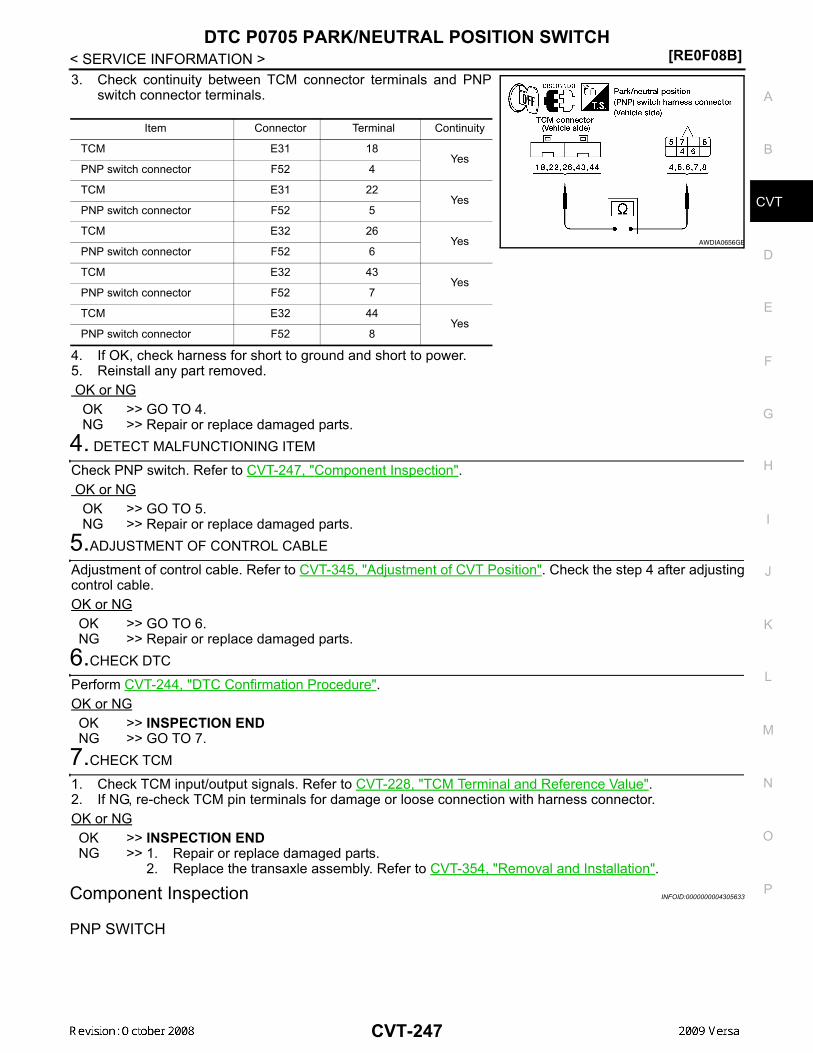
DTC P0705 PARK/NEUTRAL POSITION SWITCH[RE0F08B]
D
E
F
G
H
I
J
K
L
M
A
B
VT
N
O
P
< SERVICE INFORMATION >
C
3. Check continuity between TCM connector terminals and PNPswitch connector terminals.
4. If OK, check harness for short to ground and short to power.5. Reinstall any part removed. OK or NG OK >> GO TO 4. NG >> Repair or replace damaged parts.
4. DETECT MALFUNCTIONING ITEM
Check PNP switch. Refer to CVT-247, "Component Inspection". OK or NG OK >> GO TO 5. NG >> Repair or replace damaged parts.
5.ADJUSTMENT OF CONTROL CABLE
Adjustment of control cable. Refer to CVT-345, "Adjustment of CVT Position". Check the step 4 after adjustingcontrol cable.OK or NGOK >> GO TO 6.NG >> Repair or replace damaged parts.
6.CHECK DTC
Perform CVT-244, "DTC Confirmation Procedure".OK or NGOK >> INSPECTION ENDNG >> GO TO 7.
7.CHECK TCM
1. Check TCM input/output signals. Refer to CVT-228, "TCM Terminal and Reference Value".2. If NG, re-check TCM pin terminals for damage or loose connection with harness connector.OK or NGOK >> INSPECTION ENDNG >> 1. Repair or replace damaged parts.
2. Replace the transaxle assembly. Refer to CVT-354, "Removal and Installation".
Component Inspection INFOID:0000000004305633
PNP SWITCH
Item Connector Terminal Continuity
TCM E31 18 Yes
PNP switch connector F52 4
TCM E31 22 Yes
PNP switch connector F52 5
TCM E32 26 Yes
PNP switch connector F52 6
TCM E32 43 Yes
PNP switch connector F52 7
TCM E32 44 Yes
PNP switch connector F52 8
AWDIA0656GB
CVT-247

[RE0F08B]DTC P0705 PARK/NEUTRAL POSITION SWITCH
< SERVICE INFORMATION >1. Change selector lever to various positions to check the continu-
ity between terminals on the PNP switch and ground.
2. If NG, check continuity with control cable disconnected. (Refer to step 1 above.)3. If OK, with the control cable disconnected, adjust the control cable. Refer to CVT-345, "Adjustment of CVT
Position" .4. If NG, even when the control cable is disconnected, replace the transaxle assembly. Refer to CVT-354,
"Removal and Installation" .
Shift position Connector Terminal Continuity
“P”
F52
4 - Ground Yes
other positions No
“R”5 - Ground
Yes
other positions No
“N”6 - Ground
Yes
other positions No
“D”7 - Ground
Yes
other positions No
“L” 8 - Ground
Yes
other positions No
AWDIA0657GB
CVT-248

DTC P0710 CVT FLUID TEMPERATURE SENSOR CIRCUIT[RE0F08B]
D
E
F
G
H
I
J
K
L
M
A
B
VT
N
O
P
< SERVICE INFORMATION >
C
DTC P0710 CVT FLUID TEMPERATURE SENSOR CIRCUITDescription INFOID:0000000004305634
• The CVT fluid temperature sensor is included in the control valve assembly.• The CVT fluid temperature sensor detects the CVT fluid temperature and sends a signal to the TCM.
CONSULT-III Reference Value in Data Monitor Mode INFOID:0000000004305635
Remarks: Specification data are reference values.
On Board Diagnosis Logic INFOID:0000000004305636
• This is an OBD-II self-diagnostic item.• Diagnostic trouble code “P0710 ATF TEMP SEN/CIRC” with CONSULT-III is detected when TCM receives
an excessively low or high voltage from the sensor.
Possible Cause INFOID:0000000004305637
• Harness or connectors(Sensor circuit is open or shorted.)
• CVT fluid temperature sensor
DTC Confirmation Procedure INFOID:0000000004305638
CAUTION:Always drive vehicle at a safe speed.NOTE:If “DTC Confirmation Procedure” has been previously performed, always turn ignition switch OFF andwait at least 10 seconds before performing the next test.After the repair, touch “ERASE” on “SELF-DIAG RESULTS” and then perform the following procedure to con-firm the malfunction is eliminated.
WITH CONSULT-III1. Turn ignition switch ON. (Do not start engine.)2. Select “DATA MONITOR” mode for “TRANSMISSION” with CONSULT-III.3. Start engine and maintain the following conditions for at least 10 minutes (Total).
VEHICLE SPEED: 10 km/h (6 MPH) or moreENG SPEED: 450 rpm more thanACC PEDAL OPEN: More than 1.0/8RANGE: “D” position
4. If DTC is detected, go to CVT-251, "Diagnosis Procedure".
WITH GSTFollow the procedure “WITH CONSULT-III”.
Item name Condition Display value (Approx.)
ATF TEMP SEN When CVT fluid temperature is 20°C (68°F). 2.0 V
When CVT fluid temperature is 80°C (176°F). 1.0 V
CVT-249

[RE0F08B]DTC P0710 CVT FLUID TEMPERATURE SENSOR CIRCUIT
< SERVICE INFORMATION >Wiring Diagram - CVT - FTS INFOID:0000000004305639
TCM TERMINALS AND REFERENCE VALUESRefer to CVT-228, "TCM Terminal and Reference Value".
AADWA0018GB
CVT-250

DTC P0710 CVT FLUID TEMPERATURE SENSOR CIRCUIT[RE0F08B]
D
E
F
G
H
I
J
K
L
M
A
B
VT
N
O
P
< SERVICE INFORMATION >
C
Diagnosis Procedure INFOID:0000000004305640
1. CHECK CVT FLUID TEMPERATURE SENSOR SIGNAL
With CONSULT-III1. Start engine.2. Select “ECU INPUT SIGNALS” in “DATA MONITOR” mode for “TRANSMISSION” with CONSULT-III.3. Read out the value of “ATF TEMP SEN”.
Without CONSULT-III1. Start engine.2. Check voltage between TCM connector terminals.
3. Turn ignition switch OFF.4. Disconnect TCM connector.5. Check if there is continuity between connector terminal and
ground.OK or NGOK >> GO TO 5.NG >> GO TO 2.
2. CHECK CVT FLUID TEMPERATURE SENSOR CIRCUIT
1. Turn ignition switch OFF.2. Disconnect the TCM connector.3. Check resistance between TCM connector terminals.
OK or NGOK >> GO TO 5.NG >> GO TO 3.
3. CHECK CVT FLUID TEMPERATURE SENSOR
1. Turn ignition switch OFF.2. Disconnect CVT unit harness connector.
Item name Condition Display value (Approx.)
ATF TEMP SEN
When CVT fluid temperature is 20°C (68°F). 2.0 V
When CVT fluid temperature is 80°C (176°F). 1.0 V
Name Connector Terminal Temperature °C (°F)
Voltage (Approx.)
CVT fluid tem-perature sen-sor
E32 47 - 4220 (68) 2.0 V
80 (176) 1.0 V
SCIA2027E
Name Connector Terminal Temperature °C (°F)
Resistance (Approx.)
CVT fluid tem-perature sensor E32 47 - 42
20 (68) 6.5 kΩ
80 (176) 0.9 kΩ
SCIA2510E
CVT-251

[RE0F08B]DTC P0710 CVT FLUID TEMPERATURE SENSOR CIRCUIT
< SERVICE INFORMATION >3. Check resistance between CVT unit harness connector termi-
nals.
4. Reinstall any part removed.OK or NGOK >> GO TO 4.NG >> Replace the transaxle assembly. Refer to CVT-354, "Removal and Installation".
4. CHECK HARNESS BETWEEN TCM AND CVT FLUID TEMPERATURE SENSOR
1. Turn ignition switch OFF.2. Disconnect the TCM connector and CVT unit harness connector.3. Check continuity between TCM connector terminals and CVT
unit harness connector terminals.
4. If OK, check harness for short to ground and short to power.5. Reinstall any part removed. OK or NG OK >> GO TO 5. NG >> Repair or replace damaged parts.
5.CHECK DTC
Perform CVT-249, "DTC Confirmation Procedure" .OK or NGOK >> INSPECTION ENDNG >> GO TO 6.
6.CHECK TCM
1. Check TCM input/output signals. Refer to CVT-228, "TCM Terminal and Reference Value" .2. If NG, re-check TCM pin terminals for damage or loose connection with harness connector.OK or NGOK >> INSPECTION ENDNG >> Repair or replace damaged parts.
Component Inspection INFOID:0000000004305641
CVT FLUID TEMPERATURE SENSOR1. Turn ignition switch OFF.2. Disconnect CVT unit harness connector.
Name Connector Terminal Tempera-ture °C (°F)
Resistance (Approx.)
CVT fluid temperature sensor
F46 17 - 1920 (68) 6.5 kΩ
80 (176) 0.9 kΩ
SCIA4679E
Item Connector Terminal Continuity
TCM E32 42Yes
CVT unit harness connector F46 19
TCM E32 47Yes
CVT unit harness connector F46 17
SCIA4680E
CVT-252

DTC P0710 CVT FLUID TEMPERATURE SENSOR CIRCUIT[RE0F08B]
D
E
F
G
H
I
J
K
L
M
A
B
VT
N
O
P
< SERVICE INFORMATION >
C
3. Check resistance between CVT unit harness connector termi-nals.
4. If NG, replace the transaxle assembly. Refer to CVT-354,"Removal and Installation" .
Name Connector Terminal Tempera-ture °C (°F)
Resistance (Approx.)
CVT fluid temperature sensor
F46 17 - 19 20 (68) 6.5 kΩ
80 (176) 0.9 kΩ
SCIA4679E
CVT-253

[RE0F08B]DTC P0715 INPUT SPEED SENSOR CIRCUIT (PRI SPEED SENSOR)
< SERVICE INFORMATION >DTC P0715 INPUT SPEED SENSOR CIRCUIT (PRI SPEED SENSOR)Description INFOID:0000000004305642
The input speed sensor (primary speed sensor) detects the primary pulley revolution speed and sends a sig-nal to the TCM.
CONSULT-III Reference Value in Data Monitor Mode INFOID:0000000004305643
Remarks: Specification data are reference values.
On Board Diagnosis Logic INFOID:0000000004305644
• This is an OBD-II self-diagnostic item.• Diagnostic trouble code “P0715 INPUT SPD SEN/CIRC” with CONSULT-III is detected when TCM does not
receive the proper signal from the sensor.
Possible Cause INFOID:0000000004305645
• Harness or connectors(Sensor circuit is open or shorted.)
• Input speed sensor (Primary speed sensor)
DTC Confirmation Procedure INFOID:0000000004305646
CAUTION:Always drive vehicle at a safe speed.NOTE:If “DTC Confirmation Procedure” has been previously performed, always turn ignition switch OFF andwait at least 10 seconds before performing the next test.After the repair, touch “ERASE” on “SELF-DIAG RESULTS” and then perform the following procedure to con-firm the malfunction is eliminated.
WITH CONSULT-III1. Turn ignition switch ON and select “DATA MONITOR” mode for “TRANSMISSION” with CONSULT-III.2. Start engine and maintain the following conditions for at least 5 consecutive seconds.
VEHICLE SPEED: 10 km/h (6 MPH) or moreACC PEDAL OPEN: More than 1.0/8RANGE: “D” positionENG SPEED: 450 rpm or moreDriving location: Driving the vehicle uphill (increased engine load) will help maintain the drivingconditions required for this test.
3. If DTC is detected, go to CVT-256, "Diagnosis Procedure" .
WITH GSTFollow the procedure “WITH CONSULT-III”.
Item name Condition Display value
ENG SPEED SIG Engine running Closely matches the tachometer reading.
PRI SPEED SEN During driving (lock-up ON) Approximately matches the engine speed.
CVT-254

DTC P0715 INPUT SPEED SENSOR CIRCUIT (PRI SPEED SENSOR)[RE0F08B]
D
E
F
G
H
I
J
K
L
M
A
B
VT
N
O
P
< SERVICE INFORMATION >
C
Wiring Diagram - CVT - PRSCVT INFOID:0000000004305647
TCM TERMINALS AND REFERENCE VALUESRefer to CVT-228, "TCM Terminal and Reference Value".
AADWA0019GB
CVT-255

[RE0F08B]DTC P0715 INPUT SPEED SENSOR CIRCUIT (PRI SPEED SENSOR)
< SERVICE INFORMATION >Diagnosis Procedure INFOID:0000000004305648
1.CHECK INPUT SIGNALS
With CONSULT-III1. Start engine.2. Select “ECU INPUT SIGNALS” in “DATA MONITOR” mode for “TRANSMISSION” with CONSULT-III.3. Start vehicle and read out the value of “PRI SPEED SEN”.
OK or NGOK >> GO TO 6.NG >> GO TO 2.
2.CHECK INPUT SPEED SENSOR (PRIMARY SPEED SENSOR)
1. Start engine.2. Check voltage between TCM connector terminals.
3. Check the pulse with CONSULT-III or oscilloscope, when vehi-cle cruises.
OK or NGOK >> GO TO 6. NG - 1 >> Battery voltage is not supplied: GO TO 3. NG - 2 >> Battery voltage is supplied, but there is a malfunction in
the frequency: GO TO 4.3. CHECK HARNESS BETWEEN TCM AND CVT UNIT HARNESS CONNECTOR (SENSOR POWER ANDSENSOR GROUND)1. Turn ignition switch OFF.2. Disconnect TCM connector and primary speed sensor harness connector.
Item name Condition Display value
PRI SPEED SEN During driving (lock-up ON)
Approximately matches the engine speed.
Item Connector Terminal Data (Approx.)
TCM E32 10, 19 - 42 Battery voltage
Name Condition
Input speed sensor (Primary speed sensor)
When running at 20 km/h (12 MPH) in “L” position with the closed throttle position signal OFF, use the CONSULT-III pulse frequency measuring function.CAUTION:Connect the data link connector to the vehicle-side diag-nosis connector.
Item Connector Terminal Name Data (Ap-prox.)
TCM E32 38 Input speed sensor (Primary speed sensor) 1275 Hz
AWDIA0644GB
CVT-256

DTC P0715 INPUT SPEED SENSOR CIRCUIT (PRI SPEED SENSOR)[RE0F08B]
D
E
F
G
H
I
J
K
L
M
A
B
VT
N
O
P
< SERVICE INFORMATION >
C
3. Check continuity between TCM connector terminals and primaryspeed sensor harness connector terminals.
4. If OK, check harness for short to ground and short to power.5. Reinstall any part removed. OK or NG OK >> GO TO 6. NG >> Repair open circuit or short to ground or short to power in harness or connectors.
4. CHECK HARNESS BETWEEN TCM AND CVT UNIT HARNESS CONNECTOR [INPUT SPEED SENSOR(PRIMARY SPEED SENSOR)]1. Turn ignition switch OFF.2. Disconnect TCM connector and primary speed sensor harness connector.3. Check continuity between TCM connector terminal and primary
speed sensor harness connector terminal.
4. If OK, check harness for short to ground and short to power.5. Reinstall any part removed. OK or NG OK >> GO TO 5. NG >> Repair open circuit or short to ground or short to power
in harness or connectors.5. CHECK THE TCM SHORT
Replace same type TCM, perform self-diagnosis check. Erase self-diagnostic results and then drive the vehi-cle [10 km/h (6 MPH) or more], perform self-diagnosis check. Refer to CVT-254, "DTC Confirmation Proce-dure". Is the “P0715 INPUT SPD SEN/CIRC” detected again? YES >> Replace the primary speed sensor. Refer to XX_XX. NO >> Replace TCM. Refer to CVT-190, "Service After Replacing TCM and Transaxle Assembly".
6.CHECK DTC
Perform CVT-254, "DTC Confirmation Procedure".OK or NGOK >> INSPECTION ENDNG >> GO TO 7.
7.CHECK TCM
1. Check TCM input/output signals. Refer to CVT-228, "TCM Terminal and Reference Value".2. If NG, re-check TCM pin terminals for damage or loose connection with harness connector.OK or NGOK >> INSPECTION ENDNG >> Repair or replace damaged parts.
Item Connector Terminal Continuity
TCM E32 42 Yes
Primary speed sensor F50 1
TCM E32 10, 19 Yes
Primary speed sensor F50 3
AWDIA0648GB
Item Connector Terminal Continuity
TCM E32 38Yes
Primary speed sensor F50 2
AWDIA0649GB
CVT-257

[RE0F08B]DTC P0720 VEHICLE SPEED SENSOR CVT (SECONDARY SPEED SENSOR)
< SERVICE INFORMATION >DTC P0720 VEHICLE SPEED SENSOR CVT (SECONDARY SPEED SEN-SOR)Description INFOID:0000000004305649
The vehicle speed sensor CVT [output speed sensor (secondary speed sensor)] detects the revolution of theCVT output shaft and emits a pulse signal. The pulse signal is sent to the TCM, which converts it into vehiclespeed.
CONSULT-III Reference Value in Data Monitor Mode INFOID:0000000004305650
Remarks: Specification data are reference values.
On Board Diagnosis Logic INFOID:0000000004305651
• This is an OBD-II self-diagnostic item.• Diagnostic trouble code “P0720 VEH SPD SEN/CIR AT” with CONSULT-III is detected TCM does not
receive the proper signal from the sensor.
Possible Cause INFOID:0000000004305652
• Harness or connectors(Sensor circuit is open or shorted.)
• Output speed sensor (Secondary speed sensor)
DTC Confirmation Procedure INFOID:0000000004305653
CAUTION:Always drive vehicle at a safe speed.NOTE:If “DTC Confirmation Procedure” has been previously performed, always turn ignition switch OFF andwait at least 10 seconds before performing the next test.After the repair, touch “ERASE” on “SELF-DIAG RESULTS” and then perform the following procedure to con-firm the malfunction is eliminated.
WITH CONSULT-III1. Turn ignition switch ON and select “DATA MONITOR” mode for “TRANSMISSION” with CONSULT-III.2. Start engine and maintain the following conditions for at least 12 consecutive seconds.
ACC PEDAL OPEN: More than 1.0/8RANGE: “D” positionDriving location: Driving the vehicle uphill (increased engine load) will help maintain the drivingconditions required for this test.
3. If DTC is detected, go to CVT-260, "Diagnosis Procedure" .
WITH GSTFollow the procedure “WITH CONSULT-III”.
Item name Condition Display value
VSP SENSOR During driving Approximately matches the speedometer reading.
CVT-258

DTC P0720 VEHICLE SPEED SENSOR CVT (SECONDARY SPEED SENSOR)[RE0F08B]
D
E
F
G
H
I
J
K
L
M
A
B
VT
N
O
P
< SERVICE INFORMATION >
C
Wiring Diagram - CVT - SESCVT INFOID:0000000004305654
TCM TERMINALS AND REFERENCE VALUESRefer to CVT-228, "TCM Terminal and Reference Value" .
AADWA0020GB
CVT-259

[RE0F08B]DTC P0720 VEHICLE SPEED SENSOR CVT (SECONDARY SPEED SENSOR)
< SERVICE INFORMATION >Diagnosis Procedure INFOID:0000000004305655
1.CHECK INPUT SIGNAL
With CONSULT-III1. Start engine.2. Select “ECU INPUT SIGNALS” in “DATA MONITOR” mode for “TRANSMISSION” with CONSULT-III.3. Start vehicle and read out the value of “VSP SENSOR”.
OK or NGOK >> GO TO 8.NG >> GO TO 2.
2. CHECK SECONDARY SPEED SENSOR
With CONSULT-III1. Start engine.2. Check power supply to output speed sensor (secondary speed sensor) by voltage between TCM connec-
tor terminals 10, 19 and 42. Refer to CVT-219, "Circuit Diagram" .
3. If OK, check the pulse when vehicle cruises.
OK or NG OK >> GO TO 8. NG >> GO TO 3.
3. CHECK POWER AND SENSOR GROUND
1. Turn ignition switch OFF.2. Disconnect the output speed sensor (secondary speed sensor) harness connector.3. Turn ignition switch ON.
Item name Condition Display value
VSP SENSOR During driving Approximately matches the speedometer reading.
Item Connector Terminal Data (Approx.)
TCM E31, E3210 - 42
Battery voltage19 - 42
Name Condition
Output speed sen-sor (Secondary speed sensor)
When running at 20 km/h (12 MPH) in “D” position, use the CONSULT-III pulse frequency measuring function.CAUTION:Connect the data link connector to the vehicle-side diag-nosis connector.
Item Connector Terminal Name Data (Ap-prox.)
TCM E32 29 Output speed sensor (Sec-ondary speed sensor) 570 Hz
SCIA2344E
CVT-260

DTC P0720 VEHICLE SPEED SENSOR CVT (SECONDARY SPEED SENSOR)[RE0F08B]
D
E
F
G
H
I
J
K
L
M
A
B
VT
N
O
P
< SERVICE INFORMATION >
C
4. Check voltage between output speed sensor (secondary speedsensor) harness connector terminals.
5. Check voltage between output speed sensor (secondary speedsensor) harness connector terminal and ground.
6. If OK, check harness for short to ground and short to power.7. Reinstall any part removed. OK or NG OK >> GO TO 4. NG - 1 >> Battery voltage is not supplied between terminals 1 and 3, terminals 1 and ground.: GO TO 6. NG - 2 >> Battery voltage is not supplied between terminals 1 and 3 only.: GO TO 7.
4. CHECK HARNESS BETWEEN TCM AND OUTPUT SPEED SENSOR (SECONDARY SPEED SENSOR)
1. Turn ignition switch OFF.2. Disconnect TCM connector and output speed sensor (secondary speed sensor) harness connector.3. Check continuity between TCM connector terminal and output
speed sensor (secondary speed sensor) harness connector ter-minal.
4. If OK, check harness for short to ground and short to power.5. Reinstall any part removed. OK or NG OK >> GO TO 5. NG >> Repair open circuit or short to ground or short to power in harness or connectors.
5. CHECK THE TCM SHORT
Replace same type TCM, perform self-diagnosis check. Erase self-diagnostic results and them drive the vehi-cle [more than 40 km/h (25 MPH)], perform self-diagnosis check. Refer to CVT-258, "DTC Confirmation Proce-dure" . Is “P0720 VEH SPD SEN/CIR AT” detected again? YES >> Replace the secondary speed sensor. Refer to Dummy cross-reference("XX-XX"). NO >> Replace TCM. Refer to CVT-190, "Service After Replacing TCM and Transaxle Assembly" .
6. CHECK HARNESS BETWEEN TCM AND OUTPUT SPEED SENSOR (SECONDARY SPEED SENSOR)(POWER)1. Turn ignition switch OFF.2. Disconnect TCM connector and output speed sensor (secondary speed sensor) harness connector.
Item Connector Terminal Data (Ap-prox.)
Output speed sensor (Sec-ondary speed sensor) F48 3 - 1 Battery volt-
age
SCIA2345E
Item Connector Terminal Data (Ap-prox.)
Output speed sensor (Sec-ondary speed sensor) F48 3 - ground Battery volt-
age
SCIA2346E
Item Connector Terminal Continuity
TCM E32 29YesOutput speed sensor (Sec-
ondary speed sensor) F48 2
SCIA1967E
CVT-261

[RE0F08B]DTC P0720 VEHICLE SPEED SENSOR CVT (SECONDARY SPEED SENSOR)
< SERVICE INFORMATION >3. Check continuity between TCM connector terminals and output
speed sensor (secondary speed sensor) harness connector ter-minal. Refer to CVT-219, "Circuit Diagram" .
4. If OK, check harness for short to ground and short to power.5. Reinstall any part removed. OK or NG OK >> 10 A fuse (No. 49, located in the IPDM E/R) or ignition switch are malfunctioning. NG >> Repair open circuit or short to ground or short to power in harness or connectors.
7. CHECK HARNESS BETWEEN TCM AND OUTPUT SPEED SENSOR (SECONDARY SPEED SENSOR)(SENSOR GROUND)1. Turn ignition switch OFF.2. Disconnect TCM connector and output speed sensor (secondary speed sensor) harness connector.3. Check continuity between TCM connector terminal and output
speed sensor (secondary speed sensor) harness connector ter-minal.
4. If OK, check harness for short to ground and short to power.5. Reinstall any part removed. OK or NG OK >> GO TO 8. NG >> Repair open circuit or short to ground or short to power in harness or connectors.
8.CHECK DTC
Perform CVT-258, "DTC Confirmation Procedure" .OK or NGOK >> INSPECTION ENDNG >> GO TO 9.
9.CHECK TCM
1. Check TCM input/output signals. Refer to CVT-228, "TCM Terminal and Reference Value" .2. If NG, re-check TCM pin terminals for damage or loose connection with harness connector.OK or NGOK >> INSPECTION ENDNG >> Repair or replace damaged parts.
Item Connector Terminal Continuity
TCM E31 10YesOutput speed sensor (Sec-
ondary speed sensor) F48 3
TCM E31 19YesOutput speed sensor (Sec-
ondary speed sensor) F48 3 SCIA2369E
Item Connector Terminal Continuity
TCM E32 42YesOutput speed sensor (Sec-
ondary speed sensor) F48 1
SCIA2347E
CVT-262

DTC P0725 ENGINE SPEED SIGNAL[RE0F08B]
D
E
F
G
H
I
J
K
L
M
A
B
VT
N
O
P
< SERVICE INFORMATION >
C
DTC P0725 ENGINE SPEED SIGNALDescription INFOID:0000000004305656
The engine speed signal is sent from the ECM to the TCM.
CONSULT-III Reference Value in Data Monitor Mode INFOID:0000000004305657
Remarks: Specification data are reference values.
On Board Diagnosis Logic INFOID:0000000004305658
• This is not an OBD-II self-diagnostic item.• Diagnostic trouble code “P0725 ENGINE SPEED SIG” with CONSULT-III is detected when TCM does not
receive the engine speed signal (input by CAN communication) from ECM.
Possible Cause INFOID:0000000004305659
Harness or connectors(The ECM to the TCM circuit is open or shorted.)
DTC Confirmation Procedure INFOID:0000000004305660
CAUTION:Always drive vehicle at a safe speed.NOTE:If “DTC Confirmation Procedure” has been previously performed, always turn ignition switch OFF andwait at least 10 seconds before performing the next test.After the repair, touch “ERASE” on “SELF-DIAG RESULTS” and then perform the following procedure to con-firm the malfunction is eliminated.
WITH CONSULT-III1. Turn ignition switch ON and select “DATA MONITOR” mode for “TRANSMISSION” with CONSULT-III.2. Start engine and maintain the following conditions for at least 10 consecutive seconds.
PRI SPEED SEN: More than 1000 rpm3. If DTC is detected, go to CVT-263, "Diagnosis Procedure".
Diagnosis Procedure INFOID:0000000004305661
1. CHECK DTC WITH ECM
With CONSULT-III1. Turn ignition switch ON. (Do not start engine.)2. Select “SELF-DIAG RESULTS” mode for “ENGINE” with CONSULT-III. Refer to EC-1116, "CONSULT-III
Function (ENGINE)".OK or NGOK >> GO TO 2.NG >> Check the DTC detected item. Refer to EC-1116, "CONSULT-III Function (ENGINE)".
2. CHECK DTC WITH TCM
With CONSULT-III1. Turn ignition switch ON. (Do not start engine.)2. Select “SELF-DIAG RESULTS” mode for “TRANSMISSION” with CONSULT-III. Refer to CVT-230, "CON-
SULT-III Function (TRANSMISSION)".OK or NGOK >> GO TO 3.NG >> Check the DTC detected item. Refer to CVT-230, "CONSULT-III Function (TRANSMISSION)".
Item name Condition Display value
ENG SPEED SIG Engine running Closely matches the tachometer reading.
ACC PEDAL OPEN Released accelerator pedal - Fully depressed accel-erator pedal 0.0/8 - 8.0/8
CVT-263

[RE0F08B]DTC P0725 ENGINE SPEED SIGNAL
< SERVICE INFORMATION >• If DTC of CAN communication line is detected, go to CVT-238.
3. CHECK INPUT SIGNALS
With CONSULT-III1. Start engine.2. Select “ECU INPUT SIGNALS” in “DATA MONITOR” mode for “TRANSMISSION” with CONSULT-III.3. While monitoring “ENG SPEED SIG”, check for engine speed change corresponding to “ACC PEDAL
OPEN”.
OK or NGOK >> GO TO 4.NG >> Check ignition signal circuit. Refer to EC-1518, "Component Description".
4. CHECK DTC
Perform CVT-263, "DTC Confirmation Procedure". OK or NG OK >> INSPECTION END NG >> GO TO 5.
5. CHECK TCM
1. Check TCM input/output signals. Refer to CVT-228, "TCM Terminal and Reference Value".2. If NG, re-check TCM pin terminals for damage or loose connection with harness connector. OK or NG OK >> INSPECTION END NG >> Repair or replace damaged parts.
Item name Condition Display value
ENG SPEED SIG Engine running Closely matches the ta-chometer reading.
ACC PEDAL OPENReleased accelerator pedal - Fully depressed accelerator pedal
0.0/8 - 8.0/8
CVT-264

DTC P0730 BELT DAMAGE[RE0F08B]
D
E
F
G
H
I
J
K
L
M
A
B
VT
N
O
P
< SERVICE INFORMATION >
C
DTC P0730 BELT DAMAGEDescription INFOID:0000000004305662
TCM selects the gear ratio using the engine load (throttle position), the primary pulley revolution speed, andthe secondary pulley revolution speed as input signal. Then it changes the operating pressure of the primarypulley and the secondary pulley and changes the groove width of the pulley.
CONSULT-III Reference Value in Data Monitor Mode INFOID:0000000004305663
Remarks: Specification data are reference values.
On Board Diagnosis Logic INFOID:0000000004305664
• This is not an OBD-II self-diagnostic item. • TCM calculates the actual gear ratio with input speed sensor (primary speed sensor) and output speed sen-
sor (secondary speed sensor).• Diagnostic trouble code “P0730 BELT DAMG” with CONSULT-III is detected, when TCM receives an unex-
pected gear ratio signal.
Possible Cause INFOID:0000000004305665
Transaxle assembly
DTC Confirmation Procedure INFOID:0000000004305666
CAUTION:Always drive vehicle at a safe speed.NOTE:If “DTC Confirmation Procedure” has been previously performed, always turn ignition switch OFF andwait at least 10 seconds before performing the next test.After the repair, perform the following procedure to confirm the malfunction is eliminated.
WITH CONSULT-III1. Turn ignition switch ON and select “DATA MONITOR” mode for “TRANSMISSION” with CONSULT-III.2. Make sure that output voltage of CVT fluid temperature sensor is within the range below.
ATF TEMP SEN: 1.0 - 2.0 VIf out of range, drive the vehicle to decrease the voltage (warm up the fluid) or stop engine toincrease the voltage (cool down the fluid)
3. Select “DATA MONITOR” mode for “TRANSMISSION” with CONSULT-III.4. Start engine and maintain the following conditions for at least 30 consecutive seconds.
TEST START FROM 0 km/h (0 MPH)CONSTANT ACCELERATION: Keep 30 sec or moreVEHICLE SPEED: 10 km/h (6 MPH) or moreACC PEDAL OPEN: More than 1.0/8RANGE: “D” positionENG SPEED: 450 rpm or more
5. If DTC is detected, go to CVT-265, "Diagnosis Procedure".
Diagnosis Procedure INFOID:0000000004305667
1.CHECK DTC
Perform CVT-265, "DTC Confirmation Procedure".Are any DTC displayed?YES - 1>> DTC except for “P0730 BELT DAMG” is displayed: Go to Check the DTC detected item. Refer to
CVT-230, "CONSULT-III Function (TRANSMISSION)".YES - 2>> DTC for “P0730 BELT DAMG” is displayed: Replace the transaxle assembly. Refer to CVT-354,
"Removal and Installation". NO >> INSPECTION END
Item name Condition Display value (Approx.)
GEAR RATIO During driving 2.56 - 0.43
CVT-265

[RE0F08B]DTC P0740 TORQUE CONVERTER CLUTCH SOLENOID VALVE
< SERVICE INFORMATION >DTC P0740 TORQUE CONVERTER CLUTCH SOLENOID VALVEDescription INFOID:0000000004305668
• The torque converter clutch solenoid valve is included in the control valve assembly.• The torque converter clutch solenoid valve is activated by the TCM in response to signals sent from the vehi-
cle speed and accelerator pedal position sensors. Lock-up piston operation will then be controlled.• Lock-up operation, however, is prohibited when CVT fluid temperature is too low.• When the accelerator pedal is depressed (less than 2.0/8) in lock-up condition, the engine speed should not
change abruptly. If there is a big jump in engine speed, there is no lock-up.
CONSULT-III Reference Value in Data Monitor Mode INFOID:0000000004305669
Remarks: Specification data are reference values.
On Board Diagnosis Logic INFOID:0000000004305670
• This is an OBD-II self-diagnostic item.• Diagnostic trouble code “P0740 TCC SOLENOID/CIRC” with CONSULT-III is detected under the following
conditions.- TCM detects an improper voltage drop when it tries to operate the solenoid valve.
Possible Cause INFOID:0000000004305671
• Torque converter clutch solenoid valve• Harness or connectors
(Solenoid circuit is open or shorted.)
DTC Confirmation Procedure INFOID:0000000004305672
NOTE:If “DTC Confirmation Procedure” has been previously performed, always turn ignition switch OFF andwait at least 10 seconds before performing the next test.After the repair, touch “ERASE” on “SELF-DIAG RESULTS” and then perform the following procedure to con-firm the malfunction is eliminated.
WITH CONSULT-III1. Turn ignition switch ON. (Do not start engine.)2. Select “DATA MONITOR” mode for “TRANSMISSION” with CONSULT-III and wait at least 10 consecutive
seconds.3. If DTC is detected, go to CVT-268, "Diagnosis Procedure" .
WITH GSTFollow the procedure “WITH CONSULT-III”.
Item name Condition Display value (Approx.)
ISOLT1Lock-up OFF 0.0 A
Lock-up ON 0.7 A
CVT-266

DTC P0740 TORQUE CONVERTER CLUTCH SOLENOID VALVE[RE0F08B]
D
E
F
G
H
I
J
K
L
M
A
B
VT
N
O
P
< SERVICE INFORMATION >
C
Wiring Diagram - CVT - TCV INFOID:0000000004305673
TCM TERMINALS AND REFERENCE VALUESRefer to CVT-228, "TCM Terminal and Reference Value" .
BCWA0674E
CVT-267

[RE0F08B]DTC P0740 TORQUE CONVERTER CLUTCH SOLENOID VALVE
< SERVICE INFORMATION >Diagnosis Procedure INFOID:0000000004305674
1.CHECK INPUT SIGNAL
With CONSULT-III1. Start engine.2. Select “MAIN SIGNALS” in “DATA MONITOR” mode for “TRANSMISSION” with CONSULT-III.3. Start vehicle and read out the value of “ISOLT1”.
Without CONSULT-III1. Start engine.2. Check voltage between TCM connector terminal and ground.
3. Turn ignition switch OFF.4. Disconnect TCM connector.5. Check if there is continuity between the connector terminal and
ground.OK or NGOK >> GO TO 5.NG >> GO TO 2.
2. CHECK TORQUE CONVERTER CLUTCH SOLENOID VALVE CIRCUIT
1. Turn ignition switch OFF.2. Disconnect TCM connector.3. Check resistance between TCM connector terminal and ground.
OK or NG OK >> GO TO 5. NG >> GO TO 3.
3. CHECK HARNESS BETWEEN TCM AND TORQUE CONVERTER CLUTCH SOLENOID VALVE
1. Turn ignition switch OFF.2. Disconnect TCM connector and CVT unit harness connector.
Item name Condition Display value (Approx.)
ISOLT1Lock-up OFF 0.0 A
Lock-up ON 0.7 A
Name Connector Terminal Condition Voltage (Approx.)
Torque con-verter clutch sole-noid valve
E31 3 - ground
When vehi-cle cruises in “D” posi-tion
Lock-up ON 6.0 V
Lock-up OFF 1.0 V
SCIA7954E
Solenoid valve Connector Terminal Resistance (Approx.)
Torque converter clutch so-lenoid valve E31 3 - Ground 3 - 9 Ω
SCIA1970E
CVT-268

DTC P0740 TORQUE CONVERTER CLUTCH SOLENOID VALVE[RE0F08B]
D
E
F
G
H
I
J
K
L
M
A
B
VT
N
O
P
< SERVICE INFORMATION >
C
3. Check continuity between TCM connector terminal and CVT unitharness connector terminal.
4. If OK, check harness for short to ground and short to power.5. If OK, check continuity between ground and CVT assembly.6. Reinstall any part removed. OK or NG OK >> GO TO 4. NG >> Repair or replace damaged parts.
4.CHECK VALVE RESISTANCE
1. Turn ignition switch OFF.2. Disconnect CVT unit harness connector.3. Check resistance between CVT unit harness connector terminal
and ground.
OK or NGOK >> GO TO 5.NG >> Repair or replace damaged parts.
5.CHECK DTC
Perform CVT-266, "DTC Confirmation Procedure" .OK or NGOK >> INSPECTION ENDNG >> GO TO 6.
6.CHECK TCM
1. Check TCM input/output signals. Refer to CVT-228, "TCM Terminal and Reference Value" .2. If NG, re-check TCM pin terminals for damage or loose connection with harness connector.OK or NGOK >> INSPECTION ENDNG >> Repair or replace damaged parts.
Component Inspection INFOID:0000000004305675
TORQUE CONVERTER CLUTCH SOLENOID VALVE1. Turn ignition switch OFF.2. Disconnect CVT unit harness connector.
Item Connector Terminal Continuity
TCM E31 3YesCVT unit harness connec-
tor F46 12
SCIA4683E
Solenoid Valve Connector Terminal Resistance (Ap-prox.)
Torque converter clutch sole-noid valve F46 12 - Ground 3 - 9 Ω
SCIA4684E
CVT-269

[RE0F08B]DTC P0740 TORQUE CONVERTER CLUTCH SOLENOID VALVE
< SERVICE INFORMATION >3. Check resistance between CVT unit harness connector terminal
and ground.
4. If NG, replace the transaxle assembly. Refer to CVT-354,"Removal and Installation" .
Solenoid Valve Connector Terminal Resistance (Ap-prox.)
Torque converter clutch sole-noid valve F46 12 - Ground 3 - 9 Ω
SCIA4684E
CVT-270

DTC P0744 A/T TCC S/V FUNCTION (LOCK-UP)[RE0F08B]
D
E
F
G
H
I
J
K
L
M
A
B
VT
N
O
P
< SERVICE INFORMATION >
C
DTC P0744 A/T TCC S/V FUNCTION (LOCK-UP)Description INFOID:0000000004305676
• The torque converter clutch solenoid valve is included in the control valve assembly.• This malfunction is detected when the torque converter clutch does not lock-up as instructed by the TCM.
This is not only caused by electrical malfunction (circuits open or shorted), but also by mechanical malfunc-tion such as control valve sticking, improper solenoid valve operation, etc.
CONSULT-III Reference Value in Data Monitor Mode INFOID:0000000004305677
Remarks: Specification data are reference values.
On Board Diagnosis Logic INFOID:0000000004305678
• This is an OBD-II self-diagnostic item.• Diagnostic trouble code “P0744 A/T TCC S/V FNCTN” with CONSULT-III is detected under the following
conditions.- When CVT cannot perform lock-up even if electrical circuit is good.- When TCM compares difference value with slip revolution and detects an irregularity.
Possible Cause INFOID:0000000004305679
• Torque converter clutch solenoid valve• Hydraulic control circuit
DTC Confirmation Procedure INFOID:0000000004305680
CAUTION:Always drive vehicle at a safe speed.NOTE:If “DTC Confirmation Procedure” has been previously performed, always turn ignition switch OFF andwait at least 10 seconds before performing the next test.After the repair, touch “ERASE” on “SELF-DIAG RESULTS” and then perform the following procedure to con-firm the malfunction is eliminated.
WITH CONSULT-III1. Turn ignition switch ON. (Do not start engine.)2. Select “DATA MONITOR” mode for “TRANSMISSION” with CONSULT-III.3. Start engine and maintain the following condition for at least 30 seconds.
ACC PEDAL OPEN: More than 1.0/8RANGE: “D” position [Vehicle speed: Constant speed of more than 40 km/h (25 MPH)]
4. If DTC is detected go to CVT-271, "Diagnosis Procedure".
WITH GSTFollow the procedure “WITH CONSULT-III”.
Diagnosis Procedure INFOID:0000000004305681
1.CHECK INPUT SIGNALS
With CONSULT-III1. Start engine.2. Select “ECU INPUT SIGNALS” in “DATA MONITOR” mode for “TRANSMISSION” with CONSULT-III.3. Start vehicle.4. Check if there is a great difference between “ENG SPEED SIG” and “PRI SPEED SEN”. (Lock-up ON.)
Item name Condition Display value
ENG SPEED SIG Engine running Closely matches the tachometer reading.
PRI SPEED SEN During driving (lock-up ON) Approximately matches the engine speed.
CVT-271

[RE0F08B]DTC P0744 A/T TCC S/V FUNCTION (LOCK-UP)
< SERVICE INFORMATION >
OK or NGOK >> GO TO 5.NG >> GO TO 2.
2.CHECK LINE PRESSURE
Perform line pressure test. Refer to CVT-219, "Inspections before Trouble Diagnosis".OK or NGOK >> GO TO 3.NG >> Repair or replace damaged parts. Refer to CVT-219, "Inspections before Trouble Diagnosis".
3.DETECT MALFUNCTIONING ITEM
Check the following:• Torque converter clutch solenoid valve. Refer to CVT-269, "Component Inspection".• Lock-up select solenoid valve. Refer to CVT-309, "Component Inspection".OK or NGOK >> GO TO 4.NG >> Repair or replace damaged parts.
4.CHECK OUTPUT SPEED SENSOR (SECONDARY SPEED SENSOR) SYSTEM AND INPUT SPEEDSENSOR (PRIMARY SPEED SENSOR) SYSTEMCheck output speed sensor (secondary speed sensor) system and input speed sensor (primary speed sensor)system. Refer to CVT-258, CVT-254.OK or NGOK >> GO TO 5.NG >> Repair or replace damaged parts.
5.CHECK DTC
Perform CVT-271, "DTC Confirmation Procedure".OK or NGOK >> INSPECTION ENDNG >> GO TO 6.
6.CHECK TCM
1. Check TCM input/output signals. Refer to CVT-228, "TCM Terminal and Reference Value".2. If NG, re-check TCM pin terminals for damage or loose connection with harness connector.OK or NGOK >> INSPECTION ENDNG >> 1. Repair or replace damaged parts.
2. Replace the transaxle assembly. Refer to CVT-354, "Removal and Installation".
Item name Condition Display value
ENG SPEED SIG Engine running Closely matches the ta-chometer reading.
PRI SPEED SEN During driving (lock-up ON) Approximately matches the engine speed.
CVT-272

DTC P0745 LINE PRESSURE SOLENOID VALVE[RE0F08B]
D
E
F
G
H
I
J
K
L
M
A
B
VT
N
O
P
< SERVICE INFORMATION >
C
DTC P0745 LINE PRESSURE SOLENOID VALVEDescription INFOID:0000000004305682
• The pressure control solenoid valve A (line pressure solenoid valve) is included in the control valve assem-bly.
• The pressure control solenoid valve A (line pressure solenoid valve) regulates the oil pump discharge pres-sure to suit the driving condition in response to a signal sent from the TCM.
CONSULT-III Reference Value in Data Monitor Mode INFOID:0000000004305683
Remarks: Specification data are reference values.
On Board Diagnosis Logic INFOID:0000000004305684
• This is an OBD-II self-diagnostic item.• Diagnostic trouble code “P0745 L/PRESS SOL/CIRC” with CONSULT-III is detected under the following
conditions.- TCM detects an improper voltage drop when it tries to operate the solenoid valve.- When TCM compares target value with monitor value and detects an irregularity.
Possible Cause INFOID:0000000004305685
• Harness or connectors(Solenoid circuit is open or shorted.)
• Pressure control solenoid valve A (Line pressure solenoid valve)
DTC Confirmation Procedure INFOID:0000000004305686
NOTE:If “DTC Confirmation Procedure” has been previously performed, always turn ignition switch OFF andwait at least 10 seconds before performing the next test.After the repair, perform the following procedure to confirm the malfunction is eliminated.
WITH CONSULT-III1. Turn ignition switch ON and select “DATA MONITOR” mode for “TRANSMISSION” with CONSULT-III.2. Start engine and wait at least 5 seconds.3. If DTC is detected, go to CVT-275, "Diagnosis Procedure".
WITH GSTFollow the procedure “WITH CONSULT-III”.
Item name Condition Display value (Approx.)
ISOLT2Release your foot from the accelerator pedal. 0.8 A
Press the accelerator pedal all the way down. 0.0 A
CVT-273

[RE0F08B]DTC P0745 LINE PRESSURE SOLENOID VALVE
< SERVICE INFORMATION >Wiring Diagram - CVT - LPSV INFOID:0000000004305687
TCM TERMINALS AND REFERENCE VALUESRefer to CVT-228, "TCM Terminal and Reference Value".
BCWA0675E
CVT-274

DTC P0745 LINE PRESSURE SOLENOID VALVE[RE0F08B]
D
E
F
G
H
I
J
K
L
M
A
B
VT
N
O
P
< SERVICE INFORMATION >
C
Diagnosis Procedure INFOID:0000000004305688
1. CHECK INPUT SIGNAL
With CONSULT-III1. Start engine.2. Select “MAIN SIGNALS” in “DATA MONITOR” mode for “TRANSMISSION” with CONSULT-III.3. Read out the value of “ISOLT2”.
Without CONSULT-III1. Start engine.2. Check voltage between TCM connector terminal and ground.
3. Turn ignition switch OFF.4. Disconnect TCM connector.5. Check if there is continuity between connector terminal and ground. OK or NG OK >> GO TO 5. NG >> GO TO 2.
2.CHECK PRESSURE CONTROL SOLENOID VALVE A (LINE PRESSURE SOLENOID VALVE) CIRCUIT
1. Turn ignition switch OFF.2. Disconnect TCM connector.3. Check resistance between TCM connector terminal and ground.
OK or NGOK >> GO TO 5.NG >> GO TO 3.
3.CHECK VALVE RESISTANCE
1. Turn ignition switch OFF.2. Disconnect CVT unit harness connector.
Item name Condition Display value (Approx.)
ISOLT2
Release your foot from the accelerator pedal. 0.8 A
Press the accelerator ped-al all the way down. 0.0 A
Name Connector Terminal Condition Voltage (Approx.)
Pressure control so-lenoid valve A (Line pres-sure sole-noid valve)
E31 1 - ground
Release your foot from the accelerator pedal. 5.0 - 7.0 V
Press the accelerator pedal all the way down. 1.0 - 3.0 V
SCIA2348E
Solenoid valve Connector Terminal Resistance (Ap-prox.)
Pressure control solenoid valve A (Line pressure solenoid valve) E31 1 - ground 3 - 9 Ω
SCIA4685E
CVT-275

[RE0F08B]DTC P0745 LINE PRESSURE SOLENOID VALVE
< SERVICE INFORMATION >3. Check resistance between CVT unit harness connector terminal
and ground.
OK or NGOK >> GO TO 4.NG >> Replace the transaxle assembly. Refer to CVT-354,
"Removal and Installation".4. CHECK HARNESS BETWEEN TCM AND PRESSURE CONTROL SOLENOID VALVE A (LINE PRES-SURE SOLENOID VALVE)1. Turn ignition switch OFF.2. Disconnect CVT unit harness connector and TCM connector.3. Check continuity between TCM connector terminal and CVT unit
harness connector terminal.
4. If OK, check harness for short to ground and short to power.5. If OK, check continuity between ground and CVT assembly.6. Reinstall any part removed.OK or NGOK >> GO TO 5.NG >> Repair open circuit or short to ground or short to power in harness or connectors.
5.CHECK DTC
Perform CVT-273, "DTC Confirmation Procedure".OK or NGOK >> INSPECTION ENDNG >> GO TO 6.
6.CHECK TCM
1. Check TCM terminals and reference values. Refer to CVT-228, "TCM Terminal and Reference Value".2. If NG, re-check TCM pin terminals for damage or loose connection with harness connector.OK or NGOK >> INSPECTION ENDNG >> 1. Repair or replace damaged parts.
2. Replace the transaxle assembly. Refer to CVT-354, "Removal and Installation".
Component Inspection INFOID:0000000004305689
PRESSURE CONTROL SOLENOID VALVE A (LINE PRESSURE SOLENOID VALVE)1. Turn ignition switch OFF.2. Disconnect CVT unit harness connector.
Solenoid valve Connector Terminal Resistance (Ap-prox.)
Pressure control solenoid valve A (Line pressure solenoid valve) F46 2 - Ground 3 - 9 Ω
SCIA4686E
Item Connector Terminal Continuity
TCM E31 1Yes
CVT unit harness connector F46 2
SCIA4687E
CVT-276

DTC P0745 LINE PRESSURE SOLENOID VALVE[RE0F08B]
D
E
F
G
H
I
J
K
L
M
A
B
VT
N
O
P
< SERVICE INFORMATION >
C
3. Check resistance between CVT unit harness connector terminaland ground.
4. If NG, replace the transaxle assembly. Refer to CVT-354,"Removal and Installation".
Solenoid valve Connector Terminal Resistance (Ap-prox.)
Pressure control solenoid valve A (Line pressure solenoid valve) F46 2 - Ground 3 - 9 Ω
SCIA4686E
CVT-277

[RE0F08B]
DTC P0746 PRESSURE CONTROL SOLENOID A PERFORMANCE (LINE PRES-SURE SOLENOID VALVE)
< SERVICE INFORMATION >DTC P0746 PRESSURE CONTROL SOLENOID A PERFORMANCE (LINEPRESSURE SOLENOID VALVE)Description INFOID:0000000004305690
• The pressure control solenoid valve A (line pressure solenoid valve) is included in the control valve assem-bly.
• The pressure control solenoid valve A (line pressure solenoid valve) regulates the oil pump discharge pres-sure to suit the driving condition in response to a signal sent from the TCM.
CONSULT-III Reference Value in Data Monitor Mode INFOID:0000000004305691
Remarks: Specification data are reference values.
On Board Diagnosis Logic INFOID:0000000004305692
• This is an OBD-II self-diagnostic item.• Diagnostic trouble code “P0746 PRS CNT SOL/A FCTN” with CONSULT-III is detected under the following
conditions.- Unexpected gear ratio was detected in the LOW side due to excessively low line pressure.
Possible Cause INFOID:0000000004305693
• Line pressure control system• Output speed sensor (Secondary speed sensor)• Input speed sensor (Primary speed sensor)
DTC Confirmation Procedure INFOID:0000000004305694
CAUTION:Always drive vehicle at a safe speed.NOTE:If “DTC Confirmation Procedure” has been previously performed, always turn ignition switch OFF andwait at least 10 seconds before performing the next test.After the repair, touch “ERASE” on “SELF-DIAG RESULTS” and then perform the following procedure to con-firm the malfunction is eliminated.
WITH CONSULT-III1. Turn ignition switch ON and select “DATA MONITOR” mode for “TRANSMISSION” with CONSULT-III.2. Start engine and maintain the following conditions for at least 10 consecutive seconds. Test start from 0
km/h (0 MPH).ATF TEMP SEN: 1.0 - 2.0 VACC PEDAL OPEN: More than 1.0/8RANGE: “D” positionVEHICLE SPEED: 10 km/h (6 MPH) More thanDriving location: Driving the vehicle uphill (increased engine load) will help maintain the drivingconditions required for this test.
3. If DTC is detected, go to CVT-278, "Diagnosis Procedure".
WITH GSTFollow the procedure “WITH CONSULT-III”.
Diagnosis Procedure INFOID:0000000004305695
1.CHECK LINE PRESSURE
Perform line pressure test. Refer to CVT-219, "Inspections before Trouble Diagnosis".OK or NGOK >> GO TO 2.NG >> Repair or replace damaged parts. Refer to CVT-219, "Inspections before Trouble Diagnosis".
Item name Condition Display value (Approx.)
PRI PRESS “N” position idle 0.4 MPa
CVT-278
DTC P0746 PRESSURE CONTROL SOLENOID A PERFORMANCE (LINE PRES-SURE SOLENOID VALVE)
[RE0F08B]
D
E
F
G
H
I
J
K
L
M
A
B
VT
N
O
P
< SERVICE INFORMATION >
C
2.DETECT MALFUNCTIONING ITEM
Check pressure control solenoid valve A (line pressure solenoid valve). Refer to CVT-276, "ComponentInspection".OK or NGOK >> GO TO 3.NG >> Repair or replace damaged parts.
3.CHECK OUTPUT SPEED SENSOR (SECONDARY SPEED SENSOR) SYSTEM AND INPUT SPEEDSENSOR (PRIMARY SPEED SENSOR) SYSTEMCheck output speed sensor (secondary speed sensor) system and input speed sensor (primary speed sensor)system. Refer to CVT-258, CVT-254.OK or NGOK >> GO TO 4.NG >> Repair or replace damaged parts.
4.DETECT MALFUNCTIONING ITEM
Check the following:• Power supply and ground circuit for TCM. Refer to CVT-296, "Wiring Diagram - CVT - POWER".• The TCM pin terminals for damage or loose connection with harness connector.OK or NGOK >> GO TO 5.NG >> Repair or replace damaged parts.
5.CHECK DTC
Perform CVT-278, "DTC Confirmation Procedure".OK or NGOK >> INSPECTION ENDNG >> Replace the transaxle assembly or TCM. Refer to CVT-354, "Removal and Installation".
CVT-279

[RE0F08B]
DTC P0776 PRESSURE CONTROL SOLENOID B PERFORMANCE (SEC PRES-SURE SOLENOID VALVE)
< SERVICE INFORMATION >DTC P0776 PRESSURE CONTROL SOLENOID B PERFORMANCE (SECPRESSURE SOLENOID VALVE)Description INFOID:0000000004305696
• The pressure control solenoid valve B (secondary pressure solenoid valve) is included in the control valveassembly.
• The pressure control solenoid valve B (secondary pressure solenoid valve) regulates the secondary pres-sure to suit the driving condition in response to a signal sent from the TCM.
CONSULT-III Reference Value in Data Monitor Mode INFOID:0000000004305697
Remarks: Specification data are reference values.
On Board Diagnosis Logic INFOID:0000000004305698
• This is an OBD-II self-diagnostic item. • Diagnostic trouble code “P0776 PRS CNT SOL/B FCTN” with CONSULT-III is detected when secondary
pressure is too high or too low compared with the commanded value while driving.
Possible Cause INFOID:0000000004305699
• Harness or connectors(Solenoid circuit is open or shorted.)
• Pressure control solenoid valve B (Secondary pressure solenoid valve system)• Transmission fluid pressure sensor A (Secondary pressure sensor)• Line pressure control system
DTC Confirmation Procedure INFOID:0000000004305700
CAUTION:Always drive vehicle at a safe speed.NOTE:If “DTC Confirmation Procedure” has been previously performed, always turn ignition switch OFF andwait at least 10 seconds before performing the next test.After the repair, perform the following procedure to confirm the malfunction is eliminated.
WITH CONSULT-III1. Turn ignition switch ON and select “DATA MONITOR” mode for “TRANSMISSION” with CONSULT-III.2. Start engine and maintain the following conditions for at least 30 consecutive seconds.
ATF TEMP SEN: 1.0 - 2.0 VACC PEDAL OPEN: More than 1.0/8RANGE: “D” positionVEHICLE SPEED: 10 km/h (6 MPH) More thanDriving location: Driving the vehicle uphill (increased engine load) will help maintain the drivingconditions required for this test.
3. If DTC is detected, go to CVT-280, "Diagnosis Procedure".
WITH GSTFollow the procedure “WITH CONSULT-III”.
Diagnosis Procedure INFOID:0000000004305701
1.CHECK INPUT SIGNAL
With CONSULT-III1. Start engine.2. Select “MAIN SIGNALS” in “DATA MONITOR” mode for “TRANSMISSION” with CONSULT-III.3. Start vehicle and read out the value of “SEC PRESS”.
Item name Condition Display value (Approx.)
SEC PRESS “N” position idle 0.8 MPa
CVT-280

DTC P0776 PRESSURE CONTROL SOLENOID B PERFORMANCE (SEC PRES-SURE SOLENOID VALVE)
[RE0F08B]
D
E
F
G
H
I
J
K
L
M
A
B
VT
N
O
P
< SERVICE INFORMATION >
C
OK or NGOK >> GO TO 5.NG >> GO TO 2.
2.CHECK LINE PRESSURE
Perform line pressure test. Refer to CVT-219, "Inspections before Trouble Diagnosis".OK or NGOK >> GO TO 3.NG >> Repair or replace damaged parts. Refer to CVT-219, "Inspections before Trouble Diagnosis".
3.DETECT MALFUNCTIONING ITEM
Check the following:• Pressure control solenoid valve B (Secondary pressure solenoid valve). Refer to CVT-285, "Component
Inspection".• Pressure control solenoid valve A (Line pressure solenoid valve). Refer to CVT-276, "Component Inspec-
tion".OK or NGOK >> GO TO 4.NG >> Repair or replace damaged parts.
4.CHECK TRANSMISSION FLUID PRESSURE SENSOR A (SECONDARY PRESSURE SENSOR) SYS-TEMCheck transmission fluid pressure sensor A (secondary pressure sensor) system. Refer to CVT-287.OK or NGOK >> GO TO 5.NG >> Repair or replace damaged parts.
5.DETECT MALFUNCTIONING ITEM
Check the following:• Power supply and ground circuit for TCM. Refer to CVT-296, "Wiring Diagram - CVT - POWER".• The TCM pin terminals for damage or loose connection with harness connector.OK or NGOK >> GO TO 6.NG >> Repair or replace damaged parts.
6.CHECK DTC
Perform CVT-280, "DTC Confirmation Procedure".OK or NGOK >> INSPECTION ENDNG >> Replace the transaxle assembly. Refer to CVT-354, "Removal and Installation".
Item name Condition Display value (Approx.)
SEC PRESS “N” position idle 0.8 MPa
CVT-281

[RE0F08B]
DTC P0778 PRESSURE CONTROL SOLENOID B ELECTRICAL (SEC PRES-SURE SOLENOID VALVE)
< SERVICE INFORMATION >DTC P0778 PRESSURE CONTROL SOLENOID B ELECTRICAL (SECPRESSURE SOLENOID VALVE)Description INFOID:0000000004305702
• The pressure control solenoid valve B (secondary pressure solenoid valve) is included in the control valveassembly.
• The pressure control solenoid valve B (secondary pressure solenoid valve) regulates the oil pump dischargepressure to suit the driving condition in response to a signal sent from the TCM.
CONSULT-III Reference Value in Data Monitor Mode INFOID:0000000004305703
Remarks: Specification data are reference values.
On Board Diagnosis Logic INFOID:0000000004305704
• This is an OBD-II self-diagnostic item.• Diagnostic trouble code “P0778 PRS CNT SOL/B CIRC” with CONSULT-III is detected under the following
conditions.- TCM detects an improper voltage drop when it tries to operate the solenoid valve.- When TCM compares target value with monitor value and detects an irregularity.
Possible Cause INFOID:0000000004305705
• Harness or connectors(Solenoid circuit is open or shorted.)
• Pressure control solenoid valve B (Secondary pressure solenoid valve)
DTC Confirmation Procedure INFOID:0000000004305706
NOTE:If “DTC Confirmation Procedure” has been previously performed, always turn ignition switch OFF andwait at least 10 seconds before performing the next test.After the repair, perform the following procedure to confirm the malfunction is eliminated.
WITH CONSULT-III1. Turn ignition switch ON.2. Select “DATA MONITOR” mode for “TRANSMISSION” with CONSULT-III.3. Start engine and wait at least 5 seconds.4. If DTC is detected, go to CVT-284, "Diagnosis Procedure" .
WITH GSTFollow the procedure “WITH CONSULT-III”.
Item name Condition Display value (Approx.)
ISOLT3 Secondary pressure low - Secondary pressure high 0.8 - 0.0 A
SOLMON3“N” position idle 0.6 - 0.7 A
When stalled 0.4 - 0.6 A
CVT-282

DTC P0778 PRESSURE CONTROL SOLENOID B ELECTRICAL (SEC PRES-SURE SOLENOID VALVE)
[RE0F08B]
D
E
F
G
H
I
J
K
L
M
A
B
VT
N
O
P
< SERVICE INFORMATION >
C
Wiring Diagram - CVT - SECPSV INFOID:0000000004305707
TCM TERMINALS AND REFERENCE VALUESRefer to CVT-228, "TCM Terminal and Reference Value" .
BCWA0676E
CVT-283

[RE0F08B]
DTC P0778 PRESSURE CONTROL SOLENOID B ELECTRICAL (SEC PRES-SURE SOLENOID VALVE)
< SERVICE INFORMATION >Diagnosis Procedure INFOID:0000000004305708
1. CHECK INPUT SIGNAL
With CONSULT-III1. Start engine.2. Select “MAIN SIGNALS” in “DATA MONITOR” mode for “TRANSMISSION” with CONSULT-III.3. Read out the value of “ISOLT3”.
Without CONSULT-III1. Start engine.2. Check voltage between TCM connector terminal and ground.
3. Turn ignition switch OFF.4. Disconnect TCM connector.5. Check if there is continuity between connector terminal and ground. OK or NG OK >> GO TO 5. NG >> GO TO 2.
2.CHECK PRESSURE CONTROL SOLENOID VALVE B (SECONDARY PRESSURE SOLENOID VALVE)CIRCUIT1. Turn ignition switch OFF.2. Disconnect TCM connector.3. Check resistance between TCM connector terminal and ground.
OK or NGOK >> GO TO 5.NG >> GO TO 3.
3.CHECK VALVE RESISTANCE
1. Turn ignition switch OFF.2. Disconnect CVT unit harness connector.
Item name Condition Display value (Approx.)
ISOLT3 Secondary pressure low - Secondary pressure high 0.8 - 0.0 A
Name Connector Terminal Condition Voltage (Approx.)
Pressure control so-lenoid valve B (Second-ary pres-sure solenoid valve)
E31 2 - ground
Release your foot from the accelerator pedal. 5.0 - 7.0 V
Press the accelerator pedal all the way down. 3.0 - 4.0 V
SCIA4506E
Solenoid valve Connector Terminal Resistance (Ap-prox.)
Pressure control solenoid valve B (Secondary pres-sure solenoid valve)
E31 2 - Ground 3 - 9 Ω
SCIA4507E
CVT-284

DTC P0778 PRESSURE CONTROL SOLENOID B ELECTRICAL (SEC PRES-SURE SOLENOID VALVE)
[RE0F08B]
D
E
F
G
H
I
J
K
L
M
A
B
VT
N
O
P
< SERVICE INFORMATION >
C
3. Check resistance between CVT unit harness connector terminaland ground.
OK or NGOK >> GO TO 4.NG >> Repair or replace damaged parts.
4.CHECK HARNESS BETWEEN TCM AND PRESSURE CONTROL SOLENOID VALVE B (SECONDARYPRESSURE SOLENOID VALVE)1. Turn ignition switch OFF.2. Disconnect TCM connector and CVT unit harness connector.3. Check continuity between TCM connector terminal and CVT unit
harness connector terminal.
4. If OK, check harness for short to ground and short to power.5. Reinstall any part removed.OK or NGOK >> GO TO 5.NG >> Repair or replace damaged parts.
5.CHECK DTC
Perform CVT-282, "DTC Confirmation Procedure" .OK or NGOK >> INSPECTION ENDNG >> GO TO 6.
6.CHECK TCM
1. Check TCM input/output signals. Refer to CVT-228, "TCM Terminal and Reference Value" .2. If NG, re-check TCM pin terminals for damage or loose connection with harness connector.OK or NGOK >> INSPECTION ENDNG >> 1. Repair or replace damaged parts.
2. Replace the transaxle assembly. Refer to CVT-354, "Removal and Installation" .
Component Inspection INFOID:0000000004305709
PRESSURE CONTROL SOLENOID VALVE B (SECONDARY PRESSURE SOLENOID VALVE)1. Turn ignition switch OFF.2. Disconnect CVT unit harness connector.
Solenoid valve Connector Terminal Resistance (Ap-prox.)
Pressure control solenoid valve B (Secondary pres-sure solenoid valve)
F46 3 - Ground 3 - 9 Ω
SCIA4688E
Item Connector Terminal Continuity
TCM connector E31 2YesCVT unit harness connec-
tor F46 3
SCIA4689E
CVT-285

[RE0F08B]
DTC P0778 PRESSURE CONTROL SOLENOID B ELECTRICAL (SEC PRES-SURE SOLENOID VALVE)
< SERVICE INFORMATION >3. Check resistance between CVT unit harness connector terminal
and ground.
4. If NG, replace the transaxle assembly. Refer to CVT-354,"Removal and Installation" .
Solenoid Valve Connector Terminal Resistance (Ap-prox.)
Pressure control sole-noid valve B (Secondary pressure solenoid valve)
F46 3 - Ground 3 - 9 Ω
SCIA4688E
CVT-286

DTC P0840 TRANSMISSION FLUID PRESSURE SENSOR A CIRCUIT (SEC PRESSURE SENSOR)
[RE0F08B]
D
E
F
G
H
I
J
K
L
M
A
B
VT
N
O
P
< SERVICE INFORMATION >
C
DTC P0840 TRANSMISSION FLUID PRESSURE SENSOR A CIRCUIT(SEC PRESSURE SENSOR)Description INFOID:0000000004305710
• The transmission fluid pressure sensor A (secondary pressure sensor) is included in the control valveassembly.
• The transmission fluid pressure sensor A (secondary pressure sensor) detects secondary pressure of CVTand sends TCM the signal.
CONSULT-III Reference Value in Data Monitor Mode INFOID:0000000004305711
Remarks: Specification data are reference values.
On Board Diagnosis Logic INFOID:0000000004305712
• This is an OBD-II self-diagnostic item.• Diagnostic trouble code “P0840 TR PRS SENS/A CIRC” with CONSULT-III is detected when TCM detects
an improper voltage drop when it receives the sensor signal.
Possible Cause INFOID:0000000004305713
• Transmission fluid pressure sensor A (Secondary pressure sensor)• Harness or connectors
(Switch circuit is open or shorted.)
DTC Confirmation Procedure INFOID:0000000004305714
NOTE:If “DTC Confirmation Procedure” has been previously performed, always turn ignition switch OFF andwait at least 10 seconds before performing the next test.After the repair, perform the following procedure to confirm the malfunction is eliminated.
WITH CONSULT-III1. Turn ignition switch ON and select “DATA MONITOR” mode for “TRANSMISSION” with CONSULT-III.2. Make sure that output voltage of line temperature sensor is within the range below.
ATF TEMP SEN: 1.0 - 2.0 VIf out of range, drive the vehicle to decrease the voltage (warm up the fluid) or stop engine toincrease the voltage (cool down the fluid)
3. Start engine and wait for at least 5 consecutive seconds.4. If DTC is detected, go to CVT-289, "Diagnosis Procedure" .
WITH GSTFollow the procedure “WITH CONSULT-III”.
Item name Condition Display value (Approx.)
SEC HYDR SEN“N” position idle
1.0 V
SEC PRESS 0.8 MPa
CVT-287

[RE0F08B]
DTC P0840 TRANSMISSION FLUID PRESSURE SENSOR A CIRCUIT (SEC PRESSURE SENSOR)
< SERVICE INFORMATION >Wiring Diagram - CVT - SECPS INFOID:0000000004305715
TCM TERMINALS AND REFERENCE VALUESRefer to CVT-228, "TCM Terminal and Reference Value".
AADWA0021GB
CVT-288

DTC P0840 TRANSMISSION FLUID PRESSURE SENSOR A CIRCUIT (SEC PRESSURE SENSOR)
[RE0F08B]
D
E
F
G
H
I
J
K
L
M
A
B
VT
N
O
P
< SERVICE INFORMATION >
C
Diagnosis Procedure INFOID:0000000004305716
1.CHECK INPUT SIGNAL
With CONSULT-III1. Start engine.2. Select “ECU INPUT SIGNALS” in “DATA MONITOR” mode for “TRANSMISSION” with CONSULT-III.3. Start vehicle and read out the value of “SEC HYDR SEN”.
Without CONSULT-III1. Start engine.2. Check voltage between TCM connector terminal and ground.
OK or NGOK >> GO TO 5.NG >> GO TO 2.
2.CHECK SENSOR POWER AND SENSOR GROUND
1. Turn ignition switch ON. (Do not start engine)2. Check voltage between TCM connector terminals.
OK or NGOK >> GO TO 4.NG >> GO TO 3.
3. CHECK HARNESS BETWEEN TCM AND CVT UNIT HARNESS CONNECTOR (SENSOR POWER ANDSENSOR GROUND)1. Turn ignition switch OFF.2. Disconnect TCM connector and CVT unit harness connector.3. Check continuity between TCM connector terminals and CVT
unit harness connector terminals.
4. If OK, check harness for short to ground and short to power.5. Reinstall any part removed. OK or NG
Item name Condition Display value (Approx.)
SEC HYDR SEN “N” position idle 1.0 V
Name Connector Terminal Condition Voltage (Approx.)
Transmission fluid pressure sensor A (Secondary pressure sen-sor)
E32 37 - Ground “N” position idle 1.0 V
SCIA4508E
Item Connector Terminal Data (Ap-prox.)
TCM connector E32 46 - 42 5.0 V
SCIA2367E
Item Connector Terminal Continuity
TCM E32 42Yes
CVT unit harness connector F46 19
TCM E32 46Yes
CVT unit harness connector F46 20
SCIA4681E
CVT-289

[RE0F08B]
DTC P0840 TRANSMISSION FLUID PRESSURE SENSOR A CIRCUIT (SEC PRESSURE SENSOR)
< SERVICE INFORMATION > OK >> Replace TCM. Refer to CVT-190, "Service After Replacing TCM and Transaxle Assembly" . NG >> Repair open circuit or short to ground or short to power in harness or connectors.
4.CHECK HARNESS BETWEEN TCM AND TRANSMISSION FLUID PRESSURE SENSOR A (SECOND-ARY PRESSURE SENSOR)1. Turn ignition switch OFF.2. Disconnect TCM connector and CVT unit harness connector.3. Check continuity between TCM connector terminal and CVT unit
harness connector terminal.
4. If OK, check harness for short to ground and short to power.5. Reinstall any part removed.OK or NGOK >> GO TO 5.NG >> Repair open circuit or short to ground or short to power
in harness or connectors.5.CHECK DTC
Perform CVT-287, "DTC Confirmation Procedure" .OK or NGOK >> INSPECTION ENDNG >> GO TO 6.
6.CHECK TCM
1. Check TCM input/output signals. Refer to CVT-228, "TCM Terminal and Reference Value" .2. If NG, re-check TCM pin terminals for damage or loose connection with harness connector.OK or NGOK >> Replace the transaxle assembly. Refer to CVT-354, "Removal and Installation" .NG >> Repair or replace damaged parts.
Item Connector Terminal Continuity
TCM E32 37Yes
CVT unit harness connector F46 23
SCIA4690E
CVT-290

DTC P0841 PRESSURE SENSOR FUNCTION[RE0F08B]
D
E
F
G
H
I
J
K
L
M
A
B
VT
N
O
P
< SERVICE INFORMATION >
C
DTC P0841 PRESSURE SENSOR FUNCTIONDescription INFOID:0000000004305717
Using the engine load (throttle position), the primary pulley revolution speed, and the secondary pulley revolu-tion speed as input signal, TCM changes the operating pressure of the primary pulley and the secondary pul-ley and changes the groove width of the pulley to control the gear ratio.
CONSULT-III Reference Value in Data Monitor Mode INFOID:0000000004305718
Remarks: Specification data are reference values.
On Board Diagnosis Logic INFOID:0000000004305719
• This is not an OBD-II self-diagnostic item.• Diagnostic trouble code “P0841 PRESS SEN/FNCTN” with CONSULT-III is detected when secondary fluid
pressure is too high compared with the commanded value while driving.
Possible Cause INFOID:0000000004305720
• Transmission fluid pressure sensor A (Secondary pressure sensor)• Harness or connectors
(Sensor circuit is open or shorted.)
DTC Confirmation Procedure INFOID:0000000004305721
CAUTION:Always drive vehicle at a safe speed.NOTE:If “DTC Confirmation Procedure” has been previously performed, always turn ignition switch OFF andwait at least 10 seconds before performing the next test.After the repair, perform the following procedure to confirm the malfunction is eliminated.
WITH CONSULT-III1. Turn ignition switch ON and select “DATA MONITOR” mode for “TRANSMISSION” with CONSULT-III.2. Start engine and maintain the following conditions for at least 12 consecutive seconds.
VEHICLE SPEED: 40 km/h (25 MPH) More thanRANGE: “D” position
3. If DTC is detected, go to CVT-291, "Diagnosis Procedure".
Diagnosis Procedure INFOID:0000000004305722
1.CHECK CAN COMMUNICATION LINE
Perform the self-diagnosis. Refer to CVT-230, "CONSULT-III Function (TRANSMISSION)".Is any malfunction of the “U1000 CAN COMM CIRCUIT” indicated?YES >> Check CAN communication line. Refer to CVT-238.NO >> GO TO 2.
2.CHECK INPUT SIGNALS
With CONSULT-III1. Start engine.2. Select “ECU INPUT SIGNALS” in “DATA MONITOR” mode for “TRANSMISSION” with CONSULT-III.3. Start vehicle and read out the value of “SEC HYDR SEN” and “PRI HYDR SEN”.
Item name Condition Display value (Approx.)
PRI HYDR SEN“N” position idle
0.7 V
SEC HYDR SEN 1.0 V
CVT-291

[RE0F08B]DTC P0841 PRESSURE SENSOR FUNCTION
< SERVICE INFORMATION >
Without CONSULT-III1. Start engine.2. Check voltage between TCM connector terminals and ground.
OK or NGOK >> GO TO 6.NG >> GO TO 3.
3.CHECK LINE PRESSURE
Perform line pressure test. Refer to CVT-219, "Inspections before Trouble Diagnosis".OK or NGOK >> GO TO 4.NG >> Repair or replace damaged parts. Refer to CVT-219, "Inspections before Trouble Diagnosis".
4.CHECK TRANSMISSION FLUID PRESSURE SENSOR A (SECONDARY PRESSURE SENSOR) SYS-TEMCheck transmission fluid pressure sensor A (secondary pressure sensor) system. Refer to CVT-287.OK or NGOK >> GO TO 5.NG >> Repair or replace damaged parts.
5.DETECT MALFUNCTIONING ITEM
Check the following:• Pressure control solenoid valve A (Line pressure solenoid valve). Refer to CVT-276, "Component Inspec-
tion".• Step motor. Refer to CVT-314, "Component Inspection".OK or NG6OK >> GO TO 6.NG >> Repair or replace damaged parts.
6.CHECK DTC
Perform CVT-291, "DTC Confirmation Procedure".OK or NGOK >> INSPECTION ENDNG >> Replace TCM or transaxle assembly. Refer to CVT-354, "Removal and Installation".
Item name Condition Display value (Approx.)
PRI HYDR SEN“N” position idle
0.7 V
SEC HYDR SEN 1.0 V
Name Connector Terminal Condition Voltage (Approx.)
Transmission fluid pressure sensor A (Secondary pres-sure sensor)
E32 37 - Ground “N” position idle 1.0 V
AWDIA0650GB
CVT-292

DTC P0868 SECONDARY PRESSURE DOWN[RE0F08B]
D
E
F
G
H
I
J
K
L
M
A
B
VT
N
O
P
< SERVICE INFORMATION >
C
DTC P0868 SECONDARY PRESSURE DOWNDescription INFOID:0000000004305730
• The pressure control solenoid valve B (secondary pressure solenoid valve) is included in the control valveassembly.
• The pressure control solenoid valve B (secondary pressure solenoid valve) regulates the secondary pres-sure to suit the driving condition in response to a signal sent from the TCM.
CONSULT-III Reference Value in Data Monitor Mode INFOID:0000000004305731
Remarks: Specification data are reference values.
On Board Diagnosis Logic INFOID:0000000004305732
• This is not an OBD-II self-diagnostic item. • Diagnostic trouble code “P0868 SEC/PRESS DOWN” with CONSULT-III is detected when secondary fluid
pressure is too low compared with the commanded value while driving.
Possible Cause INFOID:0000000004305733
• Harness or connectors(Solenoid circuit is open or shorted.)
• Pressure control solenoid valve B (Secondary pressure solenoid valve) system• Transmission fluid pressure sensor A (Secondary pressure sensor)• Line pressure control system
DTC Confirmation Procedure INFOID:0000000004305734
CAUTION:Always drive vehicle at a safe speed.NOTE:If “DTC Confirmation Procedure” has been previously performed, always turn ignition switch OFF andwait at least 10 seconds before performing the next test.After the repair, perform the following procedure to confirm the malfunction is eliminated.
WITH CONSULT-III1. Turn ignition switch ON and select “DATA MONITOR” mode for “TRANSMISSION” with CONSULT-III.2. Make sure that output voltage of CVT fluid temperature sensor is within the range below.
ATF TEMP SEN: 1.0 - 2.0 VIf out of range, drive the vehicle to decrease the voltage (warm up the fluid) or stop engine toincrease the voltage (cool down the fluid)
3. Start engine and maintain the following conditions for at least 10 consecutive seconds.VEHICLE SPEED (accelerate slowly): 0 → 50 km/h (31 MPH)ACC PEDAL OPEN: 0.5/8 - 1.0/8RANGE: “D” position
4. If DTC is detected, go to CVT-293, "Diagnosis Procedure".
Diagnosis Procedure INFOID:0000000004305735
1.CHECK INPUT SIGNAL
With CONSULT-III1. Start engine.2. Select “MAIN SIGNALS” in “DATA MONITOR” mode for “TRANSMISSION” with CONSULT-III.3. Start vehicle and read out the value of “SEC PRESS”.
Item name Condition Display value (Approx.)
SEC PRESS “N” position idle 0.8 MPa
Item name Condition Display value (Approx.)
SEC PRESS “N” position idle 0.8 MPa
CVT-293

[RE0F08B]DTC P0868 SECONDARY PRESSURE DOWN
< SERVICE INFORMATION >OK or NGOK >> GO TO 5.NG >> GO TO 2.
2.CHECK LINE PRESSURE
Perform line pressure test. Refer to CVT-219, "Inspections before Trouble Diagnosis".OK or NGOK >> GO TO 3.NG >> Repair or replace damaged parts. Refer to CVT-219, "Inspections before Trouble Diagnosis".
3.DETECT MALFUNCTIONING ITEM
Check the following:• Pressure control solenoid valve B (Secondary pressure solenoid valve). Refer to CVT-285, "Component
Inspection".• Pressure control solenoid valve A (Line pressure solenoid valve). Refer to CVT-276, "Component Inspec-
tion".OK or NGOK >> GO TO 4.NG >> Repair or replace damaged parts.
4.CHECK TRANSMISSION FLUID PRESSURE SENSOR A (SECONDARY PRESSURE SENSOR) SYS-TEMCheck transmission fluid pressure sensor A (secondary pressure sensor) system. Refer to CVT-287.OK or NGOK >> GO TO 5.NG >> Repair or replace damaged parts.
5.DETECT MALFUNCTIONING ITEM
Check the following:• Power supply and ground circuit for TCM. Refer to CVT-296, "Wiring Diagram - CVT - POWER".• The TCM pin terminals for damage or loose connection with harness connector.OK or NGOK >> GO TO 6.NG >> Repair or replace damaged parts.
6.CHECK DTC
Perform CVT-293, "DTC Confirmation Procedure".OK or NGOK >> INSPECTION ENDNG >> Replace the transaxle assembly. Refer to CVT-354, "Removal and Installation".
CVT-294

DTC P1701 TRANSMISSION CONTROL MODULE (POWER SUPPLY)[RE0F08B]
D
E
F
G
H
I
J
K
L
M
A
B
VT
N
O
P
< SERVICE INFORMATION >
C
DTC P1701 TRANSMISSION CONTROL MODULE (POWER SUPPLY)Description INFOID:0000000004305736
When the power supply to the TCM is cut OFF, for example because the battery is removed, and the self-diag-nosis memory function stops, malfunction is detected.NOTE:Since “P1701 TCM-POWER SUPPLY” will be indicated when replacing TCM, perform diagnosis aftererasing “SELF-DIAG RESULTS”
On Board Diagnosis Logic INFOID:0000000004305737
• This is not an OBD-II self-diagnostic item.• Diagnostic trouble code “P1701 TCM-POWER SUPPLY” with CONSULT-III is detected when TCM does not
receive the voltage signal from the battery power supply.• This is not a malfunction message. (Whenever shutting OFF a power supply to the TCM, this message
appears on the screen.)
Possible Cause INFOID:0000000004305738
Harness or connectors(Battery or ignition switch and TCM circuit is open or shorted.)
DTC Confirmation Procedure INFOID:0000000004305739
NOTE:If “DTC Confirmation Procedure” has been previously conducted, always turn ignition switch OFF andwait at least 10 seconds before conducting the next test.After the repair, perform the following procedure to confirm the malfunction is eliminated.
WITH CONSULT-III1. Turn ignition switch ON. (Do not start engine.)2. Select “DATA MONITOR” mode for “TRANSMISSION” with CONSULT-III.3. Wait for at least 2 consecutive seconds.4. If DTC is detected, go to CVT-297, "Diagnosis Procedure" .
CVT-295

[RE0F08B]DTC P1701 TRANSMISSION CONTROL MODULE (POWER SUPPLY)
< SERVICE INFORMATION >Wiring Diagram - CVT - POWER INFOID:0000000004305740
TCM TERMINALS AND REFERENCE VALUESRefer to CVT-228, "TCM Terminal and Reference Value" .
AADWA0023GB
CVT-296

DTC P1701 TRANSMISSION CONTROL MODULE (POWER SUPPLY)[RE0F08B]
D
E
F
G
H
I
J
K
L
M
A
B
VT
N
O
P
< SERVICE INFORMATION >
C
Diagnosis Procedure INFOID:0000000004305741
1.CHECK DTC
1. Turn ignition switch ON. (Do not start engine.)2. Select “SELF-DIAG RESULTS” mode for “TRANSMISSION” with CONSULT-III.3. Erase self-diagnostic results. Refer to CVT-209, "OBD-II Diagnostic Trouble Code (DTC)" .4. Turn ignition switch OFF, and wait for 5 seconds or more.5. Start engine.6. Confirm self-diagnostic results again. Refer to CVT-230, "CONSULT-III Function (TRANSMISSION)" .Is the “P1701 TCM-POWER SUPPLY” displayed?YES >> GO TO 2.NO >> INSPECTION END
2.CHECK TCM POWER SOURCE, STEP 1
1. Turn ignition switch OFF.2. Check voltage between TCM connector terminal and ground.
OK or NGOK >> GO TO 3.NG >> GO TO 4.
3.CHECK TCM POWER SOURCE, STEP 2
1. Turn ignition switch ON. (Do not start engine.)2. Check voltage between TCM connector terminals and ground.
OK or NGOK >> GO TO 5.NG >> GO TO 4.
4.DETECT MALFUNCTIONING ITEM
Check the following.• Harness for short or open between battery and TCM connector terminal 28• Harness for short or open between ignition switch and TCM connector terminal 10, 19
Name Connector Terminal Condition Voltage (Approx.)
Power supply (memory back-up)
E32 28, 30 - Ground Always Battery voltage
AWDIA0651GB
Name Connector Terminal Condition Voltage (Approx.)
Power supply
E31
10 - Ground
Battery voltage
0 V
Power supply 19 - Ground
Battery voltage
0 V
Power supply (memory back-up)
E32 28, 30 - Ground Always Battery voltage
AWDIA0652GB
CVT-297

[RE0F08B]DTC P1701 TRANSMISSION CONTROL MODULE (POWER SUPPLY)
< SERVICE INFORMATION >• 10 A fuse (No.49, located in the IPDM E/R) • 20 A fuse (No.53, located in the IPDM E/R) • Ignition switch. Refer to PG-3 .OK or NGOK >> GO TO 5.NG >> Repair or replace damaged parts.
5.CHECK TCM GROUND CIRCUIT
1. Turn ignition switch OFF.2. Disconnect TCM connector.3. Check continuity between TCM connector terminals and ground.
OK or NGOK >> GO TO 6.NG >> Repair open circuit or short to ground or short to power
in harness or connectors.
6.CHECK DTC
Perform CVT-295, "DTC Confirmation Procedure" .OK or NGOK >> INSPECTION ENDNG >> GO TO 7.
7.CHECK TCM
1. Check TCM input/output signals. Refer to CVT-228, "TCM Terminal and Reference Value" .2. If NG, re-check TCM pin terminals for damage or loose connection with harness connector.OK or NGOK >> INSPECTION ENDNG >> Repair or replace damaged parts.
Name Connector Terminal Continuity
Ground E3225
Yes48
SCIA2671E
CVT-298

DTC P1705 THROTTLE POSITION SENSOR[RE0F08B]
D
E
F
G
H
I
J
K
L
M
A
B
VT
N
O
P
< SERVICE INFORMATION >
C
DTC P1705 THROTTLE POSITION SENSORDescription INFOID:0000000004305742
Electric throttle control actuator consists of throttle control motor, accelerator pedal position sensor, throttleposition sensor etc. The actuator sends a signal to the ECM, and ECM sends the signal to TCM with CANcommunication.
CONSULT-III Reference Value in Data Monitor Mode INFOID:0000000004305743
Remarks: Specification data are reference values.
On Board Diagnosis Logic INFOID:0000000004305744
• This is not an OBD-II self-diagnostic item.• Diagnostic trouble code “P1705 TP SEN/CIRC A/T” with CONSULT-III is detected when TCM does not
receive the proper accelerator pedal position signals (input by CAN communication) from ECM.
Possible Cause INFOID:0000000004305745
• ECM• Harness or connectors
(CAN communication line is open or shorted.)
DTC Confirmation Procedure INFOID:0000000004305746
NOTE:If “DTC Confirmation Procedure” has been previously performed, always turn ignition switch OFF andwait at least 10 seconds before performing the next test.After the repair, perform the following procedure to confirm the malfunction is eliminated.
WITH CONSULT-III1. Turn ignition switch ON. (Do not start engine.)2. Select “DATA MONITOR” mode for “TRANSMISSION” with CONSULT-III.3. Depress accelerator pedal fully and release it, then wait for 5 seconds.4. If DTC is detected, go to CVT-299, "Diagnosis Procedure".
Diagnosis Procedure INFOID:0000000004305747
1.CHECK CAN COMMUNICATION LINE
Perform the self-diagnosis check. Refer to CVT-230, "CONSULT-III Function (TRANSMISSION)".Is any malfunction of the “U1000 CAN COMM CIRCUIT” indicated?YES >> Check the CAN communication line. Refer to CVT-238.NO >> GO TO 2.
2.CHECK INPUT SIGNAL
With CONSULT-III1. Turn ignition switch ON. (Do not start engine.)2. Select “ECU INPUT SIGNALS” in “DATA MONITOR” mode for “TRANSMISSION” with CONSULT-III.3. Read out the value of “ACC PEDAL OPEN”.
OK or NG
Item name Condition Display value (Approx.)
ACC PEDAL OPEN Released accelerator pedal - Fully depressed accelerator pedal 0.0/8 - 8.0/8
Item name Condition Display value (Approx.)
ACC PEDAL OPEN
Release accelerator ped-al.↓
Fully depressed acceler-ator pedal
0.0/8↓
8.0/8
CVT-299
[RE0F08B]DTC P1705 THROTTLE POSITION SENSOR
< SERVICE INFORMATION >OK >> GO TO 4.NG >> GO TO 3.
3.CHECK DTC WITH ECM
With CONSULT-III1. Turn ignition switch ON. (Do not start engine.)2. Select “SELF-DIAG RESULTS” mode for “ENGINE” with CONSULT-III. Refer to EC-1116, "CONSULT-III
Function (ENGINE)".OK or NGOK >> GO TO 4.NG >> Check the DTC Detected Item. Go to EC-1116, "CONSULT-III Function (ENGINE)".
4.CHECK DTC
Perform CVT-299, "DTC Confirmation Procedure".OK or NGOK >> INSPECTION ENDNG >> Repair or replace damaged parts.
CVT-300

DTC P1722 ESTM VEHICLE SPEED SIGNAL[RE0F08B]
D
E
F
G
H
I
J
K
L
M
A
B
VT
N
O
P
< SERVICE INFORMATION >
C
DTC P1722 ESTM VEHICLE SPEED SIGNALDescription INFOID:0000000004305748
The vehicle speed signal is transmitted from ABS actuator and electric unit (control unit) to TCM by CAN com-munication line.
CONSULT-III Reference Value in Data Monitor Mode INFOID:0000000004305749
Remarks: Specification data are reference values.
On Board Diagnosis Logic INFOID:0000000004305750
• This is not an OBD-II self-diagnostic item.• Diagnostic trouble code “P1722 ESTM VEH SPD SIG” with CONSULT-III is detected when TCM does not
receive the proper vehicle speed signal (input by CAN communication) from ABS actuator and electric unit(control unit).
Possible Cause INFOID:0000000004305751
• Harness or connectors(Sensor circuit is open or shorted.)
• ABS actuator and electric unit (control unit)
DTC Confirmation Procedure INFOID:0000000004305752
CAUTION:Always drive vehicle at a safe speed.NOTE:If “DTC Confirmation Procedure” has been previously performed, always turn ignition switch OFF andwait at least 10 seconds before performing the next test.After the repair, touch “ERASE” on “SELF-DIAG RESULTS” and then perform the following procedure to con-firm the malfunction is eliminated.
WITH CONSULT-III1. Turn ignition switch ON. (Do not start engine.)2. Select “DATA MONITOR” mode for “TRANSMISSION” with CONSULT-III.3. Start engine and maintain the following conditions for at least 5 consecutive seconds.
ACC PEDAL OPEN: 1.0/8 or lessVEHICLE SPEED SE: 30 km/h (17 MPH) or more
4. If DTC is detected, go to CVT-301, "Diagnosis Procedure".
Diagnosis Procedure INFOID:0000000004305753
1.CHECK CAN COMMUNICATION LINE
Perform the self-diagnosis check. Refer to CVT-230, "CONSULT-III Function (TRANSMISSION)".Is any malfunction of the “U1000 CAN COMM CIRCUIT” indicated?YES >> Check CAN communication line. Refer to CVT-238.NO >> GO TO 2.
2.CHECK ABS ACTUATOR AND ELECTRIC UNIT (CONTROL UNIT)
Perform ABS actuator and electric unit (control unit) self-diagnosis check. Refer to BRC-18, "CONSULT-IIIFunction (ABS)".OK or NGOK >> GO TO 3.NG >> Repair or replace damaged parts.
Item name Condition Display value
ESTM VSP SIGDuring driving Approximately matches the speedometer reading.
VEHICLE SPEED
CVT-301

[RE0F08B]DTC P1722 ESTM VEHICLE SPEED SIGNAL
< SERVICE INFORMATION >
3.CHECK INPUT SIGNALS
With CONSULT-III1. Start engine.2. Select “SELECTION FROM MENU” in “DATA MONITOR” mode for “TRANSMISSION” with CONSULT-III.3. Drive vehicle and read out the value of “VEHICLE SPEED” and “ESTM VSP SIG”.
4. Check if there is a great difference between the two values.
OK or NGOK >> GO TO 5.NG >> GO TO 4.
4.CHECK TCM
Check TCM input/output signals. Refer to CVT-228, "TCM Terminal and Reference Value".OK or NGOK >> GO TO 5.NG >> Repair or replace damaged parts.
5.CHECK DTC
Perform CVT-301, "DTC Confirmation Procedure".OK or NGOK >> INSPECTION ENDNG >> GO TO 2.
Item name Condition Display value
ESTM VSP SIGDuring driving Approximately matches
the speedometer reading.VEHICLE SPEED
CVT-302

DTC P1723 CVT SPEED SENSOR FUNCTION[RE0F08B]
D
E
F
G
H
I
J
K
L
M
A
B
VT
N
O
P
< SERVICE INFORMATION >
C
DTC P1723 CVT SPEED SENSOR FUNCTIONDescription INFOID:0000000004305754
• The input speed sensor (primary speed sensor) is included in the control valve assembly.• The vehicle speed sensor CVT [output speed sensor (secondary speed sensor)] detects the revolution of the
idler gear and generates a pulse signal. The pulse signal is sent to the TCM, which converts it into vehiclespeed.
• The input speed sensor (primary speed sensor) detects the primary pulley revolution speed and sends a sig-nal to the TCM.
On Board Diagnosis Logic INFOID:0000000004305755
• This is not an OBD-II self-diagnostic item.• Diagnostic trouble code “P1723 CVT SPD SEN/FNCTN” with CONSULT-III is detected when there is a great
difference between the vehicle speed signal and the secondary speed sensor signal.CAUTION:One of the “P0720 VEH SPD SEN/CIR AT”, the “P0715 INPUT SPD SEN/CIRC” or the “P0725 ENGINESPEED SIG“ is displayed with the DTC at the same time.
Possible Cause INFOID:0000000004305756
• Harness or connectors(Sensor circuit is open or shorted.)
• Output speed sensor (Secondary speed sensor)• Input speed sensor (Primary speed sensor)• Engine speed signal system
DTC Confirmation Procedure INFOID:0000000004305757
CAUTION:Always drive vehicle at a safe speed.NOTE:If “DTC Confirmation Procedure” has been previously performed, always turn ignition switch OFF andwait at least 10 seconds before performing the next test.After the repair, touch “ERASE” on “SELF-DIAG RESULTS” and then perform the following procedure to con-firm the malfunction is eliminated.
WITH CONSULT-III1. Turn ignition switch ON and select “DATA MONITOR” mode for “TRANSMISSION” with CONSULT-III.2. Start engine and maintain the following conditions for at least 5 consecutive seconds.
VEHICLE SPEED SE: 10 km/h (6 MPH) or moreACC PEDAL OPEN: More than 1.0/8RANGE: “D” positionENG SPEED: 450 rpm or moreDriving location: Driving the vehicle uphill (increased engine load) will help maintain the drivingconditions required for this test.
3. If DTC is detected, go to CVT-303, "Diagnosis Procedure".
Diagnosis Procedure INFOID:0000000004305758
1.CHECK STEP MOTOR FUNCTION
Perform the self-diagnosis check. Refer to CVT-230, "CONSULT-III Function (TRANSMISSION)".Is a malfunction in the step motor function indicated in the results?YES >> Repair or replace damaged parts. (Check the step motor function. Refer to CVT-315.)NO >> GO TO 2.
2.CHECK OUTPUT SPEED SENSOR (SECONDARY SPEED SENSOR SYSTEM) AND INPUT SPEEDSENSOR (PRIMARY SPEED SENSOR) SYSTEMCheck output speed sensor (secondary speed sensor) system and input speed sensor (primary speed sensor)system. Refer to CVT-258, CVT-254.
CVT-303

[RE0F08B]DTC P1723 CVT SPEED SENSOR FUNCTION
< SERVICE INFORMATION >OK or NGOK >> GO TO 3.NG >> Repair or replace damaged parts.
3.CHECK ENGINE SPEED SIGNAL SYSTEM
Check engine speed signal system. Refer to CVT-263.OK or NGOK >> GO TO 4.NG >> Repair or replace damaged parts. Refer to EC-1518, "Component Description".
4.DETECT MALFUNCTIONING ITEM
Check the following:• Power supply and ground circuit for TCM. Refer to CVT-295.• The TCM pin terminals for damage or loose connection with harness connector.OK or NGOK >> GO TO 5.NG >> Repair or replace damaged parts.
5.CHECK DTC
Perform CVT-303, "DTC Confirmation Procedure".OK or NGOK >> INSPECTION ENDNG >> Replace TCM or transaxle assembly. Refer to CVT-190, "Service After Replacing TCM and Tran-
saxle Assembly", CVT-354, "Removal and Installation".
CVT-304

DTC P1726 ELECTRIC THROTTLE CONTROL SYSTEM[RE0F08B]
D
E
F
G
H
I
J
K
L
M
A
B
VT
N
O
P
< SERVICE INFORMATION >
C
DTC P1726 ELECTRIC THROTTLE CONTROL SYSTEMDescription INFOID:0000000004305759
Electric throttle control actuator consists of throttle control motor, accelerator pedal position sensor, throttleposition sensor etc. The actuator sends a signal to the ECM, and ECM sends the signal to TCM with CANcommunication.
On Board Diagnosis Logic INFOID:0000000004305760
• This is not an OBD-II self-diagnostic item.• Diagnostic trouble code “P1726 ELEC TH CONTROL” with CONSULT-III is detected when the electronically
controlled throttle for ECM is malfunctioning.
Possible Cause INFOID:0000000004305761
Harness or connectors(Sensor circuit is open or shorted.)
DTC Confirmation Procedure INFOID:0000000004305762
NOTE:If “DTC Confirmation Procedure” has been previously performed, always turn ignition switch OFF andwait at least 10 seconds before performing the next test.After the repair, touch “ERASE” on “SELF-DIAG RESULTS” and then perform the following procedure to con-firm the malfunction is eliminated.
WITH CONSULT-III1. Turn ignition switch ON. (Do not start engine.)2. Select “DATA MONITOR” mode for “TRANSMISSION” with CONSULT-III.3. Start engine and let it idle for 5 second.4. If DTC is detected, go to CVT-305, "Diagnosis Procedure".
Diagnosis Procedure INFOID:0000000004305763
1.CHECK DTC WITH ECM
With CONSULT-III1. Turn ignition switch ON. (Do not start engine.)2. Select “SELF-DIAG RESULTS” mode for “ENGINE” with CONSULT-III. Refer to EC-1116, "CONSULT-III
Function (ENGINE)".OK or NGOK >> GO TO 2.NG >> Check the DTC Detected Item. Refer to EC-1116, "CONSULT-III Function (ENGINE)".
• If CAN communication line is detected, go to CVT-238.2.CHECK DTC
Perform CVT-305, "DTC Confirmation Procedure".OK or NGOK >> INSPECTION ENDNG >> GO TO 3.
3.DETECT MALFUNCTIONING ITEM
Check the following:• The TCM pin terminals for damage or loose connection with harness connector.OK or NGOK >> Replace TCM. Refer to CVT-190, "Service After Replacing TCM and Transaxle Assembly".NG >> Repair or replace damaged parts.
CVT-305

[RE0F08B]DTC P1740 LOCK-UP SELECT SOLENOID VALVE CIRCUIT
< SERVICE INFORMATION >DTC P1740 LOCK-UP SELECT SOLENOID VALVE CIRCUITDescription INFOID:0000000004305764
• The lock-up select solenoid valve is included in the control valve assembly.• The lock-up select solenoid valve controls lock-up clutch pressure or forward clutch pressure (reverse brake
pressure).• When controlling lock-up clutch, the valve is turned OFF. When controlling forward clutch, it is turned ON.
CONSULT-III Reference Value in Data Monitor Mode INFOID:0000000004305765
On Board Diagnosis Logic INFOID:0000000004305766
• This is an OBD-II self-diagnostic item.• Diagnostic trouble code “P1740 LU-SLCT SOL/CIRC” with CONSULT-III is detected under the following con-
ditions.- When TCM compares target value with monitor value and detects an irregularity.
Possible Cause INFOID:0000000004305767
• Lock-up select solenoid valve• Harness or connectors
(Solenoid circuit is open or shorted.)
DTC Confirmation Procedure INFOID:0000000004305768
CAUTION:Always drive vehicle at a safe speed.NOTE:If “DTC Confirmation Procedure” has been previously performed, always turn ignition switch OFF andwait at least 10 seconds before performing the next test.After the repair, touch “ERASE” on “SELF-DIAG RESULTS” and then perform the following procedure to con-firm the malfunction is eliminated.
WITH CONSULT-III1. Turn ignition switch ON. (Do not start engine.)2. Select “DATA MONITOR” mode for “TRANSMISSION” with CONSULT-III.3. Start engine and maintain the following conditions for at least 5 consecutive seconds.
RANGE: “D” position and “N” position (At each time, wait for 5 seconds.)
4. If DTC is detected, go to CVT-308, "Diagnosis Procedure" .
WITH GSTFollow the procedure “WITH CONSULT-III”.
Item name Condition Display value
LUSEL SOL OUTSelector lever in “P” and “N” positions ON
Wait at least for 5 seconds with the selector lever in “R”, “D” and “L” positions OFF
CVT-306
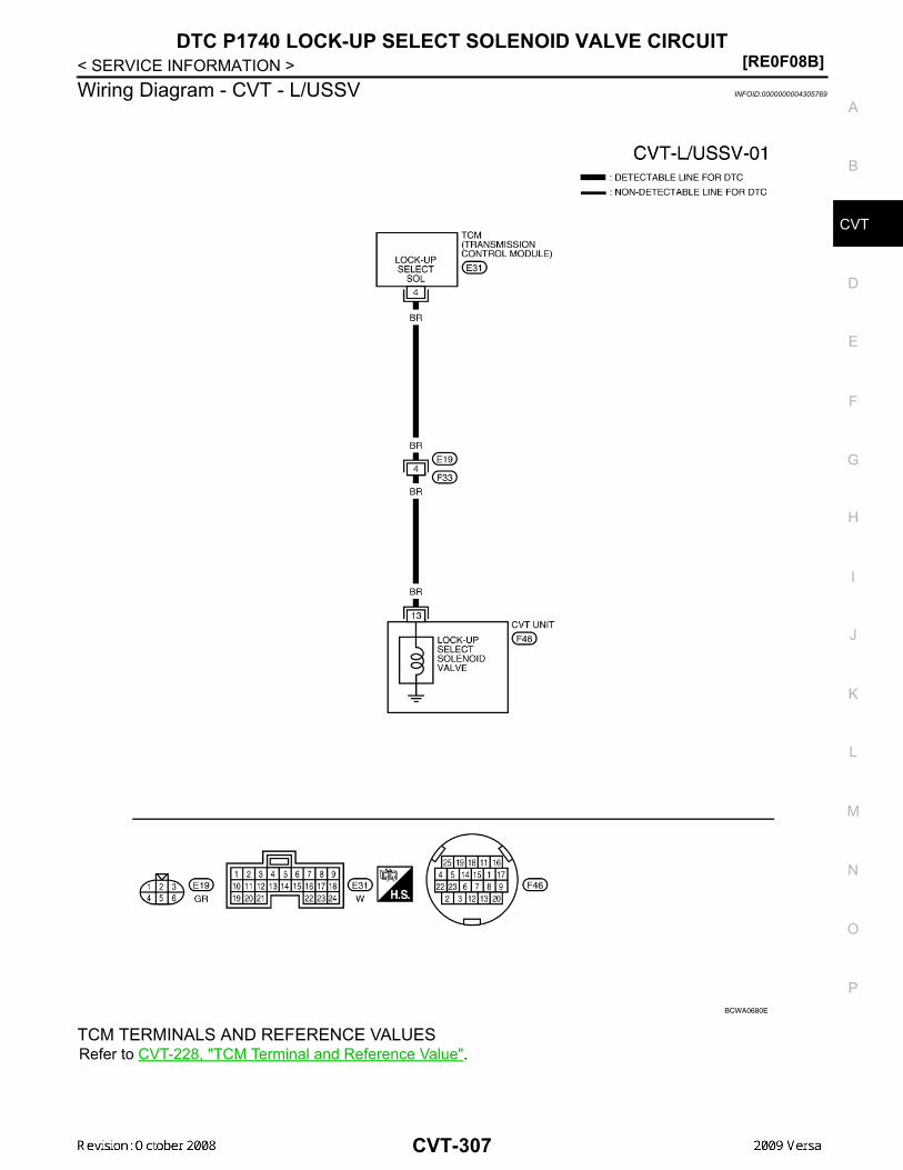
DTC P1740 LOCK-UP SELECT SOLENOID VALVE CIRCUIT[RE0F08B]
D
E
F
G
H
I
J
K
L
M
A
B
VT
N
O
P
< SERVICE INFORMATION >
C
Wiring Diagram - CVT - L/USSV INFOID:0000000004305769
TCM TERMINALS AND REFERENCE VALUESRefer to CVT-228, "TCM Terminal and Reference Value".
BCWA0680E
CVT-307

[RE0F08B]DTC P1740 LOCK-UP SELECT SOLENOID VALVE CIRCUIT
< SERVICE INFORMATION >Diagnosis Procedure INFOID:0000000004305770
1. CHECK INPUT SIGNAL
With CONSULT-III1. Turn ignition switch ON.2. Select “SELECTION FROM MENU” in “DATA MONITOR” mode for “TRANSMISSION” with CONSULT-III.3. Read out the value of “LUSEL SOL OUT”.
Without CONSULT-III1. Turn ignition switch ON.2. Check voltage between TCM connector terminal and ground.
3. Turn ignition switch OFF.4. Disconnect the TCM connector.5. Check if there is continuity between connector terminal and ground. OK or NG OK >> GO TO 5. NG >> GO TO 2.
2.CHECK LOCK-UP SELECT SOLENOID VALVE CIRCUIT
1. Turn ignition switch OFF.2. Disconnect TCM connector.3. Check resistance between TCM connector terminal and ground.
OK or NGOK >> GO TO 5.NG >> GO TO 3.
3.CHECK VALVE RESISTANCE
1. Turn ignition switch OFF.2. Disconnect CVT unit harness connector.
Item name Condition Display value
LUSEL SOL OUT
Selector lever in “P” and “N” positions ON
Wait at least for 5 seconds with the selector lever in “R”, “D” and “L” positions
OFF
Name Connector Terminal Condition Voltage (Approx.)
Lock-up select sole-noid valve
E31 4 - Ground
Selector lever in “P” and “N” positions
Battery voltage
Wait at least for 5 sec-onds with the selector le-ver in “R”, “D” and “L” positions
0 V
SCIA7955E
Solenoid valve Connector Terminal Resistance (Ap-prox.)
Lock-up select solenoid valve E31 4 - Ground 6 - 19 Ω
SCIA4692E
CVT-308

DTC P1740 LOCK-UP SELECT SOLENOID VALVE CIRCUIT[RE0F08B]
D
E
F
G
H
I
J
K
L
M
A
B
VT
N
O
P
< SERVICE INFORMATION >
C
3. Check resistance between CVT unit harness connector terminaland ground.
OK or NGOK >> GO TO 4.NG >> Replace the transaxle assembly. Refer to CVT-354,
"Removal and Installation" .4.CHECK HARNESS BETWEEN TCM AND LOCK-UP SELECT SOLENOID VALVE
1. Turn ignition switch OFF.2. Disconnect TCM connector.3. Check continuity between TCM connector terminal and CVT unit
harness connector terminal.
4. If OK, check harness for short to ground and short to power.5. Reinstall any part removed.OK or NGOK >> GO TO 5.NG >> Repair open circuit or short to ground or short to power in harness or connectors.
5.CHECK DTC
Perform CVT-306, "DTC Confirmation Procedure" .OK or NGOK >> INSPECTION ENDNG >> GO TO 6.
6.CHECK TCM
1. Check TCM input/output signals. Refer to CVT-228, "TCM Terminal and Reference Value" . 2. If NG, re-check TCM pin terminals for damage or loose connection with harness connector.OK or NGOK >> INSPECTION END NG >> 1. Repair or replace damaged parts.
2. Replace TCM. Refer to CVT-190, "Service After Replacing TCM and Transaxle Assembly" .
Component Inspection INFOID:0000000004305771
LOCK-UP SELECT SOLENOID VALVE1. Turn ignition switch OFF.2. Disconnect CVT unit harness connector.3. Check resistance between CVT unit harness connector terminal
and ground.
4. If NG, replace the transaxle assembly. Refer to CVT-354,"Removal and Installation" .
Solenoid valve Connector Terminal Resistance (Ap-prox.)
Lock-up select solenoid valve F46 13 - Ground 6 - 19 Ω
SCIA4693E
Item Connector Terminal Continuity
TCM E31 4 Yes
CVT unit harness connector F46 13
SCIA4694E
Solenoid valve Connector Terminal Resistance (Ap-prox.)
Lock-up select solenoid valve F46 13 - Ground 6 - 19 Ω
SCIA4693E
CVT-309

[RE0F08B]DTC P1745 LINE PRESSURE CONTROL
< SERVICE INFORMATION >DTC P1745 LINE PRESSURE CONTROLDescription INFOID:0000000004305772
The pressure control solenoid valve A (line pressure solenoid valve) regulates the oil pump discharge pres-sure to suit the driving condition in response to a signal sent from the TCM.
On Board Diagnosis Logic INFOID:0000000004305773
• This is not an OBD-II self-diagnostic item.• Diagnostic trouble code “P1745 L/PRESS CONTROL” with CONSULT-III is detected when TCM detects the
unexpected line pressure.
Possible Cause INFOID:0000000004305774
TCM
DTC Confirmation Procedure INFOID:0000000004305775
NOTE:If “DTC Confirmation Procedure” has been previously performed, always turn ignition switch OFF andwait at least 10 seconds before performing the next test.After the repair, touch “ERASE” on “SELF-DIAG RESULTS” and then perform the following procedure to con-firm the malfunction is eliminated.
WITH CONSULT-III1. Turn ignition switch ON and select “DATA MONITOR” mode for “TRANSMISSION” with CONSULT-III.2. Make sure that output voltage of CVT fluid temperature sensor is within the range below.
ATF TEMP SEN: 1.0 - 2.0 VIf out of range, drive the vehicle to decrease the voltage (warm up the fluid) or stop engine toincrease the voltage (cool down the fluid)
3. If DTC is detected, go to CVT-310, "Diagnosis Procedure" .
Diagnosis Procedure INFOID:0000000004305776
1.CHECK DTC
1. Turn ignition switch ON. (Do not start engine.)2. Select “SELF-DIAG RESULTS” mode for “TRANSMISSION” with CONSULT-III.3. Erase self-diagnostic results. Refer to CVT-209, "OBD-II Diagnostic Trouble Code (DTC)".4. Turn ignition switch OFF, and wait for 10 seconds or more.5. Start engine.6. Confirm self-diagnostic results again. Refer to CVT-230, "CONSULT-III Function (TRANSMISSION)" .Is the “P1745 L/PRESS CONTROL” displayed?YES >> Replace TCM. Refer to CVT-190, "Service After Replacing TCM and Transaxle Assembly" .NO >> INSPECTION END
CVT-310

DTC P1777 STEP MOTOR - CIRCUIT[RE0F08B]
D
E
F
G
H
I
J
K
L
M
A
B
VT
N
O
P
< SERVICE INFORMATION >
C
DTC P1777 STEP MOTOR - CIRCUITDescription INFOID:0000000004305777
• The step motor is included in the control valve assembly.• The step motor changes the step with turning 4 coils ON/OFF according to the signal from TCM. As a result,
the flow of line pressure to primary pulley is changed and pulley ratio is controlled
CONSULT-III Reference Value in Data Monitor Mode INFOID:0000000004305778
Remarks: Specification data are reference values.
On Board Diagnosis Logic INFOID:0000000004305779
• This is an OBD-II self-diagnostic item.• Diagnostic trouble code “P1777 STEP MOTR CIRC” with CONSULT-III is detected under the following con-
ditions.- When operating step motor ON and OFF, there is no proper change in the voltage of TCM terminal which
corresponds to it.
Possible Cause INFOID:0000000004305780
• Step motor• Harness or connectors
(Step motor circuit is open or shorted.)
DTC Confirmation Procedure INFOID:0000000004305781
CAUTION:Always drive vehicle at a safe speed.NOTE:If “DTC Confirmation Procedure” has been previously performed, always turn ignition switch OFF andwait at least 10 seconds before performing the next test.After the repair, touch “ERASE” on “SELF-DIAG RESULTS” and then perform the following procedure to con-firm the malfunction is eliminated.
WITH CONSULT-III1. Turn ignition switch ON and select “DATA MONITOR” mode for “TRANSMISSION” with CONSULT-III.2. Drive vehicle for at least 5 consecutive seconds.3. If DTC is detected, go to CVT-313, "Diagnosis Procedure" .
WITH GSTFollow the procedure “WITH CONSULT-III”.
Item name Condition Display value (Approx.)
STM STEP
During driving
−20 step - 180 step
SMCOIL A
Changes ON⇔OFF.SMCOIL B
SMCOIL C
SMCOIL D
CVT-311

[RE0F08B]DTC P1777 STEP MOTOR - CIRCUIT
< SERVICE INFORMATION >Wiring Diagram - CVT - STM INFOID:0000000004305782
TCM TERMINALS AND REFERENCE VALUESRefer to CVT-228, "TCM Terminal and Reference Value".
AADWA0024GB
CVT-312

DTC P1777 STEP MOTOR - CIRCUIT[RE0F08B]
D
E
F
G
H
I
J
K
L
M
A
B
VT
N
O
P
< SERVICE INFORMATION >
C
Diagnosis Procedure INFOID:0000000004305783
1.CHECK INPUT SIGNALS
With CONSULT-III1. Start engine.2. Select “SELECTION FROM MENU” in “DATA MONITOR” mode for “TRANSMISSION” with CONSULT-III.3. Start vehicle and read out the value of “STM STEP”, “SMCOIL A”, “SMCOIL B”, “SMCOIL C”, and
“SMCOIL D”.
OK or NGOK >> GO TO 4.NG >> GO TO 2.
2.CHECK HARNESS BETWEEN TCM AND STEP MOTOR
1. Turn ignition switch OFF.2. Disconnect CVT unit connector and TCM connector.3. Check continuity between TCM connector terminals and CVT
unit harness connector terminals.
4. If OK, check harness for short to ground and short to power.5. If OK, check continuity between body ground and CVT assembly.6. Reinstall any part removed.OK or NGOK >> GO TO 3.NG >> Repair open circuit or short to ground or short to power in harness or connectors.
3.CHECK STEP MOTOR
Check step motor. Refer to CVT-314, "Component Inspection" .OK or NGOK >> GO TO 4.NG >> Repair or replace damaged parts.
4.CHECK DTC
Perform CVT-311, "DTC Confirmation Procedure" .OK or NGOK >> INSPECTION ENDNG >> GO TO 5.
Item name Condition Display value (Approx.)
STM STEP
During driving
−20 step - 180 step
SMCOIL A
Changes ON⇔OFF.SMCOIL B
SMCOIL C
SMCOIL D
Item Connector Terminal Continuity
TCM E31 11Yes
CVT unit harness connector F46 6
TCM E31 12Yes
CVT unit harness connector F46 7
TCM E31 20Yes
CVT unit harness connector F46 8
TCM E31 21Yes
CVT unit harness connector F46 9
SCIA4695E
CVT-313

[RE0F08B]DTC P1777 STEP MOTOR - CIRCUIT
< SERVICE INFORMATION >
5.CHECK TCM
1. Check TCM input/output signals. Refer to CVT-228, "TCM Terminal and Reference Value" .2. If NG, re-check TCM pin terminals for damage or loose connection with harness connector.OK or NGOK >> INSPECTION ENDNG >> Repair or replace damaged parts.
Component Inspection INFOID:0000000004305784
STEP MOTOR1. Turn ignition switch OFF.2. Disconnect CVT unit harness connector.3. Check resistance between CVT unit harness connector termi-
nals and ground.
4. If NG, replace the transaxle assembly. Refer to CVT-354, "Removal and Installation" .
Name Connector Terminal Resistance (Ap-prox.)
Step motor F46
6 - 7 30 Ω
8 - 9
6 - Ground
15 Ω7 - Ground
8 - Ground
9 - Ground
SCIA4696E
CVT-314

DTC P1778 STEP MOTOR - FUNCTION[RE0F08B]
D
E
F
G
H
I
J
K
L
M
A
B
VT
N
O
P
< SERVICE INFORMATION >
C
DTC P1778 STEP MOTOR - FUNCTIONDescription INFOID:0000000004305785
• The step motor is included in the control valve assembly.• The step motor's 4 aspects of ON/OFF change according to the signal from TCM. As a result, the flow of line
pressure to primary pulley is changed and pulley ratio is controlled.• This diagnosis item is detected when electrical system is OK, but mechanical system is NG.• This diagnosis item is detected when the state of the changing the speed mechanism in unit does not oper-
ate normally.
CONSULT-III Reference Value in Data Monitor Mode INFOID:0000000004305786
Remarks: Specification data are reference values.
On Board Diagnosis Logic INFOID:0000000004305787
• This is an OBD-II self-diagnostic item.• Diagnostic trouble code “P1778 STEP MOTR/FNC” with CONSULT-III is detected under the following condi-
tions.- When not changing the pulley ratio according to the instruction of TCM.
Possible Cause INFOID:0000000004305788
Step motor
DTC Confirmation Procedure INFOID:0000000004305789
CAUTION:• Always drive vehicle at a safe speed.• Before starting “DTC Confirmation Procedure”, confirm “Hi” or “Mid” or “Low” fixation by “PRI
SPEED” and “VEHICLE SPEED” on “DATA MONITOR MODE”.• If hi-geared fixation occurred, go to CVT-316, "Diagnosis Procedure".NOTE:If “DTC Confirmation Procedure” has been previously performed, always turn ignition switch OFF andwait at least 10 seconds before performing the next test.After the repair, touch “ERASE” on “SELF-DIAG RESULTS” and then perform the following procedure to con-firm the malfunction is eliminated.
WITH CONSULT-III1. Turn ignition switch ON and select “DATA MONITOR” mode for “TRANSMISSION” with CONSULT-III.2. Make sure that output voltage of CVT fluid temperature sensor is within the range below.
ATF TEMP SEN: 1.0 - 2.0 VIf out of range, drive the vehicle to decrease the voltage (warm up the fluid) or stop engine toincrease the voltage (cool down the fluid)
3. Select “DATA MONITOR” mode for “TRANSMISSION” with CONSULT-III.4. Start engine and maintain the following conditions for at least 30 consecutive seconds.
TEST START FROM 0 km/h (0 MPH)CONSTANT ACCELERATION: Keep 30 sec or moreVEHICLE SPEED: 10 km/h (6 MPH) or moreACC PEDAL OPEN: More than 1.0/8RANGE: “D” positionENG SPEED: 450 rpm or more
5. If DTC is detected, go to CVT-316, "Diagnosis Procedure".
WITH GSTFollow the procedure “WITH CONSULT-III”.
Item name Condition Display value (Approx.)
STM STEPDuring driving
−20 step - 180 step
GEAR RATIO 2.56 - 0.43
CVT-315

[RE0F08B]DTC P1778 STEP MOTOR - FUNCTION
< SERVICE INFORMATION >Diagnosis Procedure INFOID:0000000004305790
1.CHECK STEP MOTOR
With CONSULT-IIIIt is monitoring whether “GEAR RATIO: 2.56 - 0.43” changes similarly to “STM STEP: −20 - 180” by DATAMONITOR mode. Refer to CVT-230, "CONSULT-III Function (TRANSMISSION)".
Without CONSULT-IIIInspect the engine speed (rise and descend), vehicle speed, throttle position, and check shift change. Refer toCVT-357, "Vehicle Speed When Shifting Gears".OK or NGOK >> INSPECTION ENDNG >> Replace the transaxle assembly. Refer to CVT-354, "Removal and Installation".
CVT-316

OVERDRIVE CONTROL SWITCH[RE0F08B]
D
E
F
G
H
I
J
K
L
M
A
B
VT
N
O
P
< SERVICE INFORMATION >
C
OVERDRIVE CONTROL SWITCHDescription INFOID:0000000004305791
• Overdrive control switch is installed to the selector lever.• O/D OFF indicator turns ON, and overdrive driving activates when pressing the overdrive control switch
while driving in “D” position. O/D OFF indicator turns OFF, and “D” position driving starts when pressing theoverdrive control switch while driving in the overdrive-off mode. Shifting the selector lever in any positionother than “D” releases the overdrive-off mode.
CONSULT-III Reference Value in Data Monitor Mode INFOID:0000000004305792
Item name Condition Display value
SPORT MODE SWWhile pushing overdrive cancel switch ON
Other conditions OFF
CVT-317

[RE0F08B]OVERDRIVE CONTROL SWITCH
< SERVICE INFORMATION >Wiring Diagram - CVT - ODSW INFOID:0000000004305793
TCM TERMINALS AND REFERENCE VALUESRefer to CVT-228, "TCM Terminal and Reference Value".
Diagnosis Procedure INFOID:0000000004305794
1.CHECK CAN COMMUNICATION LINE
AADWA0025GB
CVT-318
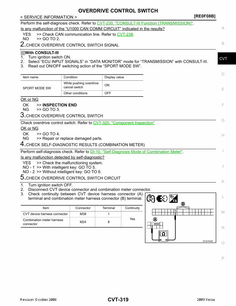
OVERDRIVE CONTROL SWITCH[RE0F08B]
D
E
F
G
H
I
J
K
L
M
A
B
VT
N
O
P
< SERVICE INFORMATION >
C
Perform the self-diagnosis check. Refer to CVT-230, "CONSULT-III Function (TRANSMISSION)".Is any malfunction of the “U1000 CAN COMM CIRCUIT” indicated in the results?YES >> Check CAN communication line. Refer to CVT-238.NO >> GO TO 2.
2.CHECK OVERDRIVE CONTROL SWITCH SIGNAL
With CONSULT-III1. Turn ignition switch ON.2. Select “ECU INPUT SIGNALS” in “DATA MONITOR” mode for “TRANSMISSION” with CONSULT-III.3. Read out ON/OFF switching action of the “SPORT MODE SW”.
OK or NGOK >> INSPECTION ENDNG >> GO TO 3.
3.CHECK OVERDRIVE CONTROL SWITCH
Check overdrive control switch. Refer to CVT-320, "Component Inspection"OK or NGOK >> GO TO 4.NG >> Repair or replace damaged parts.
4.CHECK SELF-DIAGNOSTIC RESULTS (COMBINATION METER)
Perform self-diagnosis check. Refer to DI-10, "Self-Diagnosis Mode of Combination Meter".Is any malfunction detected by self-diagnostic?YES >> Check the malfunctioning system.NO - 1 >> With intelligent key: GO TO 5.NO - 2 >> Without intelligent key: GO TO 6.
5.CHECK OVERDRIVE CONTROL SWITCH CIRCUIT
1. Turn ignition switch OFF.2. Disconnect CVT device connector and combination meter connector.3. Check continuity between CVT device harness connector (A)
terminal and combination meter harness connector (B) terminal.
Item name Condition Display value
SPORT MODE SWWhile pushing overdrive cancel switch ON
Other conditions OFF
Item Connector Terminal Continuity
CVT device harness connector M38 1YesCombination meter harness
connector M24 8
SCIA7949E
CVT-319

[RE0F08B]OVERDRIVE CONTROL SWITCH
< SERVICE INFORMATION >4. Check continuity between CVT device harness connector termi-
nal and ground.
5. If OK, check harness for short to ground and short to power.6. Reinstall any part removed.OK or NGOK >> INSPECTION ENDNG >> Repair open circuit or short to ground or short to power
in harness or connectors.6.CHECK OVERDRIVE CONTROL SWITCH CIRCUIT
1. Turn ignition switch OFF.2. Disconnect CVT device connector and combination meter connector.3. Check continuity between CVT device harness connector (A)
terminal and combination meter harness connector (B) terminal.
4. Check continuity between CVT device harness connector termi-nal and ground.
5. If OK, check harness for short to ground and short to power.6. Reinstall any part removed.OK or NGOK >> INSPECTION ENDNG >> Repair open circuit or short to ground or short to power
in harness or connectors.
Component Inspection INFOID:0000000004305795
OVERDRIVE CONTROL SWITCHWith Intelligent KeyCheck continuity between CVT device harness connector terminals.
Without Intelligent Key
Item Connector Terminal Continuity
CVT device harness connector M38 2 - ground Yes
SCIA7950E
Item Connector Terminal Continuity
CVT device harness connector M38 1YesCombination meter harness
connector M24 8
SCIA7951E
Item Connector Terminal Continuity
CVT device harness connector M38 2 - ground Yes
SCIA7952E
Item Condition Connector Terminal Continuity
Overdrive con-trol switch
While pushing overdrive control switch M38 1 - 2
Yes
Other conditions No
SCIA7942E
CVT-320

OVERDRIVE CONTROL SWITCH[RE0F08B]
D
E
F
G
H
I
J
K
L
M
A
B
VT
N
O
P
< SERVICE INFORMATION >
C
Check continuity between CVT device harness connector terminals.
Item Condition Connector Terminal Continuity
Overdrive con-trol switch
While pushing overdrive control switch M38 1 - 2
Yes
Other conditions No
SCIA7943E
CVT-321

[RE0F08B]SHIFT POSITION INDICATOR CIRCUIT
< SERVICE INFORMATION >SHIFT POSITION INDICATOR CIRCUITDescription INFOID:0000000004305796
TCM sends the switch signals to combination meter via CAN communication line. Then selector lever positionis indicated on the shift position indicator.
CONSULT-III Reference Value in Data Monitor Mode INFOID:0000000004305797
Diagnosis Procedure INFOID:0000000004305798
1.CHECK INPUT SIGNALS
With CONSULT-III1. Start engine.2. Select “MAIN SIGNALS” in “DATA MONITOR” mode for “TRANSMISSION” with CONSULT-III and read
out the value of “RANGE”.3. Check that the following three positions or indicators are same.- Actual position of the selector lever- “RANGE” on CONSULT-III screen- Shift position indicator in the combination meter OK or NGOK >> INSPECTION ENDNG >> Check the following.
SHIFT POSITION INDICATOR SYMPTOM CHART
Item name Condition Display value
RANGE
Selector lever in “N” or “P” position. N·P
Selector lever in “R” position. R
Selector lever in “D” position. D
Selector lever in “L” position. L
Items Presumed location of trouble
Actual position does not change.
Park/neutral position switch• Refer to CVT-244.CVT main system (Fail-safe function actuated)• Refer to CVT-230, "CONSULT-III Function (TRANSMISSION)".
Shift position indicator in the combination meter does not indicate any position.
Perform the self-diagnosis for CVT and the combination meter.• Refer to CVT-230, "CONSULT-III Function (TRANSMISSION)"
and DI-3.
Actual position changes, but the shift position indicator in the com-bination meter does not change.
Actual position differs from the shift position indicator in the com-bination meter.
Shift position indicator in the combination meter does not indicate specific position only.
Check the combination meter.• Refer to DI-3.
CVT-322

TROUBLE DIAGNOSIS FOR SYMPTOMS[RE0F08B]
D
E
F
G
H
I
J
K
L
M
A
B
VT
N
O
P
< SERVICE INFORMATION >
C
TROUBLE DIAGNOSIS FOR SYMPTOMSWiring Diagram - CVT - NONDTC INFOID:0000000004305799
AADWA0026GB
CVT-323

[RE0F08B]TROUBLE DIAGNOSIS FOR SYMPTOMS
< SERVICE INFORMATION >
AADWA0027GB
CVT-324

TROUBLE DIAGNOSIS FOR SYMPTOMS[RE0F08B]
D
E
F
G
H
I
J
K
L
M
A
B
VT
N
O
P
< SERVICE INFORMATION >
C
TCM TERMINALS AND REFERENCE VALUESRefer to CVT-228, "TCM Terminal and Reference Value".
O/D OFF Indicator Lamp Does Not Come On INFOID:0000000004305800
SYMPTOM:
AADWA0028GB
CVT-325

[RE0F08B]TROUBLE DIAGNOSIS FOR SYMPTOMS
< SERVICE INFORMATION >O/D OFF indicator lamp does not come on for about 2 seconds when turning ignition switch ON.
DIAGNOSTIC PROCEDURE1.CHECK CAN COMMUNICATION LINE
Perform the self-diagnosis check. Refer to CVT-230, "CONSULT-III Function (TRANSMISSION)".Is any malfunction of the “U1000 CAN COMM CIRCUIT” indicated in the results?YES >> Check CAN communication line. Refer to CVT-238.NO >> GO TO 2.
2.CHECK TCM POWER SOURCE
1. Turn ignition switch ON.2. Check voltage between TCM connector terminals and ground.
Refer to CVT-296, "Wiring Diagram - CVT - POWER".
OK or NGOK >> GO TO 4.NG >> GO TO 3.
3.DETECT MALFUNCTIONING ITEM
Check the following.• Harness for short or open between ignition switch and TCM connector terminal 10, 19
Refer to CVT-296, "Wiring Diagram - CVT - POWER".• 10 A fuse (No.49, located in the IPDM E/R). Refer to CVT-296, "Wiring Diagram - CVT - POWER". • Ignition switch. Refer to PG-3.OK or NGOK >> GO TO 4.NG >> Repair or replace damaged parts.
4.CHECK TCM GROUND CIRCUIT
1. Turn ignition switch OFF.2. Disconnect TCM connector.3. Check continuity between TCM connector terminals and ground.
Refer to CVT-296, "Wiring Diagram - CVT - POWER".
OK or NGOK >> GO TO 5.NG >> Repair open circuit or short to ground or short to power
in harness or connectors.5.DETECT MALFUNCTIONING ITEM
Check the following.• Harness and fuse for short or open between ignition switch and O/D OFF indicator lamp
Refer to PG-3.OK or NGOK >> GO TO 6.NG >> Repair or replace damaged parts.
6.CHECK SYMPTOM
Name Connec-tor Terminal Voltage (Approx.)
Power supply E3110 Battery voltage
19 Battery voltage
SCIA4737E
Name Connec-tor Terminal Continuity
Ground E3225
Yes48
SCIA2671E
CVT-326
TROUBLE DIAGNOSIS FOR SYMPTOMS[RE0F08B]
D
E
F
G
H
I
J
K
L
M
A
B
VT
N
O
P
< SERVICE INFORMATION >
C
Check again. Refer to CVT-224, "Check before Engine Is Started".OK or NGOK >> INSPECTION ENDNG >> GO TO 7.
7.CHECK COMBINATION METERS
Check combination meters. Refer to DI-3OK or NGOK >> INSPECTION ENDNG >> Repair or replace damaged parts.
Engine Cannot Be Started in "P" and "N" Position INFOID:0000000004305801
SYMPTOM:• Engine cannot be started with selector lever in “P” or “N” position.• Engine can be started with selector lever in “D”, “L” or “R” position.
DIAGNOSTIC PROCEDURE1.CHECK SELF-DIAGNOSTIC RESULTS
Perform self-diagnosis check. Refer to CVT-230, "CONSULT-III Function (TRANSMISSION)".Do the self-diagnostic results indicate PNP switch circuit?YES >> Check PNP switch circuit. Refer to CVT-244 .NO >> GO TO 2.
2.CHECK CVT POSITION
Check CVT position. Refer to CVT-345, "Checking of CVT Position"OK or NGOK >> GO TO 3.NG >> Adjust CVT position. Refer to CVT-345, "Adjustment of CVT Position".
3.CHECK STARTING SYSTEM
Check starting system. Refer to SC-9.OK or NGOK >> INSPECTION ENDNG >> Repair or replace damaged parts.
In "P" Position, Vehicle Moves Forward or Backward When Pushed INFOID:0000000004305802
SYMPTOM:Vehicle moves when it is pushed forward or backward with selector lever in “P” position.
DIAGNOSTIC PROCEDURE1.CHECK SELF-DIAGNOSTIC RESULTS
Perform self-diagnosis check. Refer to CVT-230, "CONSULT-III Function (TRANSMISSION)".Do the self-diagnostic results indicate PNP switch circuit?YES >> Check PNP switch circuit. Refer to CVT-244.NO >> GO TO 2.
2.CHECK CVT POSITION
Check CVT position. Refer to CVT-345, "Checking of CVT Position"OK or NGOK >> GO TO 3.NG >> Adjust CVT position. Refer to CVT-345, "Adjustment of CVT Position".
3.CHECK SYMPTOM
Check again. Refer to CVT-224, "Check at Idle".
CVT-327

[RE0F08B]TROUBLE DIAGNOSIS FOR SYMPTOMS
< SERVICE INFORMATION >OK or NGOK >> INSPECTION ENDNG >> Replace the transaxle assembly. Refer to CVT-354, "Removal and Installation".
In "N" Position, Vehicle Moves INFOID:0000000004305803
SYMPTOM:Vehicle moves forward or backward when selecting “N” position.
DIAGNOSTIC PROCEDURE1.CHECK SELF-DIAGNOSTIC RESULTS
Perform self-diagnosis check. Refer to CVT-230, "CONSULT-III Function (TRANSMISSION)".Do the self-diagnostic results indicate PNP switch circuit?YES >> Check PNP switch circuit. Refer to CVT-244.NO >> GO TO 2.
2.CHECK CVT POSITION
Check CVT position. Refer to CVT-345, "Checking of CVT Position"OK or NGOK >> GO TO 3.NG >> Adjust CVT position. Refer to CVT-345, "Adjustment of CVT Position".
3.CHECK CVT FLUID LEVEL
Check CVT fluid level. Refer to CVT-196, "Checking CVT Fluid".OK or NGOK >> GO TO 4.NG >> Refill CVT fluid.
4.CHECK SYMPTOM
Check again. Refer to CVT-224, "Check at Idle".OK or NGOK >> INSPECTION ENDNG >> GO TO 5.
5.CHECK TCM
1. Check TCM input/output signals. Refer to CVT-228, "TCM Terminal and Reference Value".2. If NG, re-check TCM pin terminals for damage or loose connection with harness connector.OK or NGOK >> Replace the transaxle assembly. Refer to CVT-354, "Removal and Installation".NG >> Repair or replace damaged parts.
Large Shock "N" → "R" Position INFOID:0000000004305804
SYMPTOM:There is large shock when shifting from “N” to “R” position.
DIAGNOSTIC PROCEDURE1.CHECK SELF-DIAGNOSTIC RESULTS
Perform self-diagnosis check. Refer to CVT-230, "CONSULT-III Function (TRANSMISSION)".Is any malfunction detected by self-diagnosis?YES >> Check the malfunctioning system. Refer to CVT-230, "CONSULT-III Function (TRANSMISSION)".NO >> GO TO 2.
2.CHECK ENGINE IDLE SPEED
Check the engine idle speed. Refer to EC-1082, "Idle Speed and Ignition Timing Check".OK or NG
CVT-328

TROUBLE DIAGNOSIS FOR SYMPTOMS[RE0F08B]
D
E
F
G
H
I
J
K
L
M
A
B
VT
N
O
P
< SERVICE INFORMATION >
C
OK >> GO TO 3.NG >> Repair.
3.CHECK CVT FLUID LEVEL
Check CVT fluid level. Refer to CVT-196, "Checking CVT Fluid".OK or NGOK >> GO TO 4.NG >> Refill CVT fluid.
4.CHECK LINE PRESSURE
Check line pressure at idle. Refer to CVT-219, "Inspections before Trouble Diagnosis".OK or NGOK >> GO TO 5.NG >> Check the malfunctioning item. Refer to CVT-219, "Inspections before Trouble Diagnosis".
5.SYMPTOM CHECK
Check again. Refer to CVT-224, "Check at Idle".OK or NGOK >> INSPECTION ENDNG >> GO TO 6.
6.CHECK TCM
1. Check TCM input/output signals. Refer to CVT-228, "TCM Terminal and Reference Value".2. If NG, re-check TCM pin terminals for damage or loose connection with harness connector.OK or NGOK >> Replace the transaxle assembly. Refer to CVT-354, "Removal and Installation".NG >> Repair or replace damaged parts.
Vehicle Does Not Creep Backward in "R" Position INFOID:0000000004305805
SYMPTOM:Vehicle does not creep backward when selecting “R” position.
DIAGNOSTIC PROCEDURE1.CHECK SELF-DIAGNOSTIC RESULTS
Perform self-diagnosis check. Refer to CVT-230, "CONSULT-III Function (TRANSMISSION)".Is any malfunction detected by self-diagnosisYES >> Check the malfunctioning system. Refer to CVT-230, "CONSULT-III Function (TRANSMISSION)".NO >> GO TO 2.
2.CHECK CVT POSITION
Check CVT position. Refer to CVT-345, "Checking of CVT Position"OK or NGOK >> GO TO 3.NG >> Adjust CVT position. Refer to CVT-345, "Adjustment of CVT Position".
3.CHECK CVT FLUID LEVEL
Check CVT fluid level. Refer to CVT-196, "Checking CVT Fluid".OK or NGOK >> GO TO 4.NG >> Refill CVT fluid.
4.CHECK LINE PRESSURE
Check line pressure at idle. Refer to CVT-219, "Inspections before Trouble Diagnosis".OK or NGOK >> GO TO 5.
CVT-329

[RE0F08B]TROUBLE DIAGNOSIS FOR SYMPTOMS
< SERVICE INFORMATION >NG >> Check the malfunctioning item. Refer to CVT-219, "Inspections before Trouble Diagnosis".
5.CHECK STALL REVOLUTION
Check stall revolution. Refer to CVT-219, "Inspections before Trouble Diagnosis".OK or NGOK >> GO TO 6.NG >> Check the malfunctioning item. Refer to CVT-219, "Inspections before Trouble Diagnosis".
6.CHECK SYMPTOM
Check again. Refer to CVT-224, "Check at Idle".OK or NGOK >> INSPECTION ENDNG >> GO TO 7.
7.CHECK TCM
1. Check TCM input/output signals. Refer to CVT-228, "TCM Terminal and Reference Value".2. If NG, re-check TCM pin terminals for damage or loose connection with harness connector.OK or NGOK >> Replace the transaxle assembly. Refer to CVT-354, "Removal and Installation".NG >> Repair or replace damaged parts.
Vehicle Does Not Creep Forward in "D" or "L" Position INFOID:0000000004305806
SYMPTOM:Vehicle does not creep forward when selecting “D” or “L” position.
DIAGNOSTIC PROCEDURE1.CHECK SELF-DIAGNOSTIC RESULTS
Perform self-diagnosis check. Refer to CVT-230, "CONSULT-III Function (TRANSMISSION)" .Is any malfunction detected by self-diagnosis?YES >> Check the malfunctioning system. Refer to CVT-230, "CONSULT-III Function (TRANSMISSION)"
. NO >> GO TO 2.
2.CHECK CVT POSITION
Check CVT position. Refer to CVT-345, "Checking of CVT Position"OK or NGOK >> GO TO 3.NG >> Adjust CVT position. Refer to CVT-345, "Adjustment of CVT Position" .
3.CHECK CVT FLUID LEVEL
Check CVT fluid level. Refer to CVT-196, "Checking CVT Fluid" .OK or NGOK >> GO TO 4.NG >> Refill CVT fluid.
4.CHECK LINE PRESSURE
Check line pressure at idle. Refer to CVT-219, "Inspections before Trouble Diagnosis" .OK or NGOK >> GO TO 5.NG >> Check the malfunctioning item. Refer to CVT-219, "Inspections before Trouble Diagnosis" .
5.CHECK STALL REVOLUTION
Check stall revolution. Refer to CVT-219, "Inspections before Trouble Diagnosis" .OK or NGOK >> GO TO 6.
CVT-330

TROUBLE DIAGNOSIS FOR SYMPTOMS[RE0F08B]
D
E
F
G
H
I
J
K
L
M
A
B
VT
N
O
P
< SERVICE INFORMATION >
C
NG >> Check the malfunctioning item. Refer to CVT-219, "Inspections before Trouble Diagnosis" .6.CHECK SYMPTOM
Check again. Refer to CVT-224, "Check at Idle" .OK or NGOK >> INSPECTION ENDNG >> GO TO 7.
7.CHECK TCM
1. Check TCM input/output signals. Refer to CVT-228, "TCM Terminal and Reference Value" .2. If NG, re-check TCM pin terminals for damage or loose connection with harness connector.OK or NGOK >> Replace the transaxle assembly. Refer to CVT-354, "Removal and Installation" .NG >> Repair or replace damaged parts.
Vehicle Speed Does Not Change in "L" Position INFOID:0000000004305807
SYMPTOM:Vehicle speed does not change in “L” position while the cruise test.
DIAGNOSTIC PROCEDURE1.CHECK SELF-DIAGNOSTIC RESULTS
Perform self-diagnosis check. Refer to CVT-230, "CONSULT-III Function (TRANSMISSION)" .Is any malfunction detected by self-diagnosis?YES >> Check the malfunctioning system. Refer to CVT-230, "CONSULT-III Function (TRANSMISSION)"
. NO >> GO TO 2.
2.CHECK CVT POSITION
Check CVT position. Refer to CVT-345, "Checking of CVT Position"OK or NGOK >> GO TO 3.NG >> Adjust CVT position. Refer to CVT-345, "Adjustment of CVT Position" .
3.CHECK CVT FLUID LEVEL
Check CVT fluid level. Refer to CVT-196, "Checking CVT Fluid" .OK or NGOK >> GO TO 4.NG >> Refill CVT fluid.
4.CHECK LINE PRESSURE
Check line pressure at idle. Refer to CVT-219, "Inspections before Trouble Diagnosis" .OK or NGOK >> GO TO 5.NG >> Check the malfunctioning item. Refer to CVT-219, "Inspections before Trouble Diagnosis" .
5.CHECK STALL REVOLUTION
Check stall revolution. Refer to CVT-219, "Inspections before Trouble Diagnosis" .OK or NGOK >> GO TO 6.NG >> Check the malfunctioning item. Refer to CVT-219, "Inspections before Trouble Diagnosis" .
6.CHECK SYMPTOM
Check again. Refer to CVT-226, "Cruise Test" .OK or NGOK >> INSPECTION END
CVT-331

[RE0F08B]TROUBLE DIAGNOSIS FOR SYMPTOMS
< SERVICE INFORMATION >NG >> GO TO 7.
7.CHECK TCM
1. Check TCM input/output signals. Refer to CVT-228, "TCM Terminal and Reference Value" .2. If NG, re-check TCM pin terminals for damage or loose connection with harness connector.OK or NGOK >> Replace the transaxle assembly. Refer to CVT-354, "Removal and Installation" .NG >> Repair or replace damaged parts.
Vehicle Speed Does Not Change in overdrive-off mode INFOID:0000000004305808
SYMPTOM:Vehicle speed does not change in overdrive-off mode while the cruise test.
DIAGNOSTIC PROCEDURE1.CHECK SELF-DIAGNOSTIC RESULTS
Perform self-diagnosis check. Refer to CVT-230, "CONSULT-III Function (TRANSMISSION)" .Is any malfunction detected by self-diagnosis?YES >> Check the malfunctioning system. Refer to CVT-230, "CONSULT-III Function (TRANSMISSION)"
. NO >> GO TO 2.
2.CHECK OVERDRIVE CONTROL SWITCH
Check overdrive control switch. Refer to CVT-317 .OK or NGOK >> GO TO 3.NG >> Repair or replace damaged parts.
3.CHECK CVT FLUID LEVEL
Check CVT fluid level. Refer to CVT-196, "Checking CVT Fluid" .OK or NGOK >> GO TO 4.NG >> Refill CVT fluid.
4.CHECK LINE PRESSURE
Check line pressure at idle. Refer to CVT-219, "Inspections before Trouble Diagnosis" .OK or NGOK >> GO TO 5.NG >> Check the malfunctioning item. Refer to CVT-219, "Inspections before Trouble Diagnosis" .
5.CHECK STALL REVOLUTION
Check stall revolution. Refer to CVT-219, "Inspections before Trouble Diagnosis" .OK or NGOK >> GO TO 6.NG >> Check the malfunctioning item. Refer to CVT-219, "Inspections before Trouble Diagnosis" .
6.CHECK SYMPTOM
Check again. Refer to CVT-226, "Cruise Test" .OK or NGOK >> INSPECTION ENDNG >> GO TO 7.
7.CHECK TCM
1. Check TCM input/output signals. Refer to CVT-228, "TCM Terminal and Reference Value" .2. If NG, re-check TCM pin terminals for damage or loose connection with harness connector.OK or NG
CVT-332
TROUBLE DIAGNOSIS FOR SYMPTOMS[RE0F08B]
D
E
F
G
H
I
J
K
L
M
A
B
VT
N
O
P
< SERVICE INFORMATION >
C
OK >> Replace the transaxle assembly. Refer to CVT-354, "Removal and Installation" .NG >> Repair or replace damaged parts.
Vehicle Speed Does Not Change in "D" Position INFOID:0000000004305809
SYMPTOM:Vehicle speed does not change in “D” position while the cruise test.
DIAGNOSTIC PROCEDURE1.CHECK SELF-DIAGNOSTIC RESULTS
Perform self-diagnosis check. Refer to CVT-230, "CONSULT-III Function (TRANSMISSION)" .Is any malfunction detected by self-diagnosis?YES >> Check the malfunctioning system. Refer to CVT-230, "CONSULT-III Function (TRANSMISSION)"
. NO >> GO TO 2.
2.CHECK CVT POSITION
Check CVT position. Refer to CVT-345, "Checking of CVT Position"OK or NGOK >> GO TO 3.NG >> Adjust CVT position. Refer to CVT-345, "Adjustment of CVT Position" .
3.CHECK CVT FLUID LEVEL
Check CVT fluid level. Refer to CVT-196, "Checking CVT Fluid" .OK or NGOK >> GO TO 4.NG >> Refill CVT fluid.
4.CHECK LINE PRESSURE
Check line pressure at idle. Refer to CVT-219, "Inspections before Trouble Diagnosis" .OK or NGOK >> GO TO 5.NG >> Check the malfunctioning item. Refer to CVT-219, "Inspections before Trouble Diagnosis" .
5.CHECK STALL REVOLUTION
Check stall revolution. Refer to CVT-219, "Inspections before Trouble Diagnosis" .OK or NGOK >> GO TO 6.NG >> Check the malfunctioning item. Refer to CVT-219, "Inspections before Trouble Diagnosis" .
6.CHECK SYMPTOM
Check again. Refer to CVT-226, "Cruise Test" .OK or NGOK >> INSPECTION ENDNG >> GO TO 7.
7.CHECK TCM
1. Check TCM input/output signals. Refer to CVT-228, "TCM Terminal and Reference Value" .2. If NG, re-check TCM pin terminals for damage or loose connection with harness connector.OK or NGOK >> Replace the transaxle assembly. Refer to CVT-354, "Removal and Installation" .NG >> Repair or replace damaged parts.
Vehicle Does Not Decelerate by Engine Brake INFOID:0000000004305810
SYMPTOM:Engine brake does not operate when releasing the accelerator pedal while the cruise test.
CVT-333

[RE0F08B]TROUBLE DIAGNOSIS FOR SYMPTOMS
< SERVICE INFORMATION >DIAGNOSTIC PROCEDURE1.CHECK SELF-DIAGNOSTIC RESULTS
Perform self-diagnosis check. Refer to CVT-230, "CONSULT-III Function (TRANSMISSION)" .Is any malfunction detected by self-diagnosis?YES >> Check the malfunctioning system. Refer to CVT-230, "CONSULT-III Function (TRANSMISSION)"
.NO >> GO TO 2.
2.CHECK CVT POSITION
Check CVT position. Refer to CVT-345, "Checking of CVT Position"OK or NGOK >> GO TO 3.NG >> Adjust CVT position. Refer to CVT-345, "Adjustment of CVT Position" .
3.CHECK CVT FLUID LEVEL
Check CVT fluid level. Refer to CVT-196, "Checking CVT Fluid" .OK or NGOK >> GO TO 4.NG >> Refill CVT fluid.
4.CHECK LINE PRESSURE
Check line pressure at idle. Refer to CVT-219, "Inspections before Trouble Diagnosis" .OK or NGOK >> GO TO 5.NG >> Check the malfunctioning item. Refer to CVT-219, "Inspections before Trouble Diagnosis" .
5.CHECK SYMPTOM
Check again. Refer to CVT-226, "Cruise Test" .OK or NGOK >> INSPECTION ENDNG >> GO TO 6.
6.CHECK TCM
1. Check TCM input/output signals. Refer to CVT-228, "TCM Terminal and Reference Value" .2. If NG, re-check TCM pin terminals for damage or loose connection with harness connector.OK or NGOK >> Replace the transaxle assembly. Refer to CVT-354, "Removal and Installation" .NG >> Repair or replace damaged parts.
CVT-334

CVT SHIFT LOCK SYSTEM[RE0F08B]
D
E
F
G
H
I
J
K
L
M
A
B
VT
N
O
P
< SERVICE INFORMATION >
C
CVT SHIFT LOCK SYSTEMDescription INFOID:0000000004305812
• The mechanical key interlock mechanism also operates as a shift lock:With the ignition switch turned to ON, selector lever cannot be shifted from “P” position to any other positionunless brake pedal is depressed.With the key removed, selector lever cannot be shifted from “P” position to any other position.The key cannot be removed unless selector lever is placed in “P” position.
• The shift lock and key interlock mechanisms are controlled by the ON-OFF operation of the shift lock sole-noid and by the operation of the rotator and slider located inside key cylinder, respectively.
Shift Lock System Electrical Parts Location INFOID:0000000004305813
1. Key interlock cable 2. Key cylinder 3. Stop lamp switch4. Brake pedal 5. Shift lock release button 6. Key interlock cable7. Shift lock solenoid 8. Park position switch
BCIA0034E
CVT-335

[RE0F08B]CVT SHIFT LOCK SYSTEM
< SERVICE INFORMATION >Wiring Diagram - CVT - SHIFT INFOID:0000000004305814
Diagnosis Procedure INFOID:0000000004305815
SYMPTOM 1:• Selector lever cannot be moved from “P” position with ignition switch in ON position and brake
pedal depressed.
BCWA0685E
CVT-336

CVT SHIFT LOCK SYSTEM[RE0F08B]
D
E
F
G
H
I
J
K
L
M
A
B
VT
N
O
P
< SERVICE INFORMATION >
C
• Selector lever can be moved from “P” position with ignition key in ON position and brake pedalreleased.
• Selector lever can be moved from “P” position when ignition switch is removed from key cylinder.SYMPTOM 2:• Ignition key cannot be removed when selector lever is set to “P” position.• Ignition key can be removed when selector lever is set to any position except “P” position.1.CHECK KEY INTERLOCK CABLE
Check key interlock cable for damage.OK or NGOK >> GO TO 2.NG >> Repair key interlock cable. Refer to AT-218, "Removal and Installation".
2.CHECK CVT POSITION
Check CVT position. Refer to CVT-345, "Checking of CVT Position". OK or NGOK >> GO TO 3.NG >> Adjust control cable. Refer to CVT-345, "Adjustment of CVT Position".
3.CHECK SHIFT LOCK SOLENOID AND PARK POSITION SWITCH
1. Turn ignition switch ON. (Do not start engine.)2. Selector lever is set in “P” position.3. Check operation sound.
OK or NGOK >> INSPECTION ENDNG - 1 >> With intelligent key: GO TO 4.NG - 2 >> Without intelligent key: GO TO 5.
4.CHECK POWER SOURCE
1. Turn ignition switch ON. (Do not start engine.)2. Check voltage between CVT device harness connector terminal
5 and ground.
OK or NGOK >> GO TO 8.NG >> GO TO 6.
5.CHECK POWER SOURCE
1. Turn ignition switch ON. (Do not start engine.)
Condition Brake pedal Operation sound
When ignition switch is turned to ON position and selector lever is set in “P” position.
Depressed Yes
Released No
Voltage:Brake pedal depressed: Battery voltageBrake pedal released: 0V
SCIA7934E
CVT-337

[RE0F08B]CVT SHIFT LOCK SYSTEM
< SERVICE INFORMATION >2. Check voltage between CVT device harness connector terminal
5 and ground.
OK or NGOK >> GO TO 9.NG >> GO TO 6.
6.CHECK STOP LAMP SWITCH
1. Turn ignition switch OFF.2. Disconnect stop lamp switch harness connector.3. Check continuity between stop lamp switch harness connector
terminals 3 and 4.
Check stop lamp switch after adjusting brake pedal. Refer toBR-6.OK or NGOK >> GO TO 7.NG >> Repair or replace damaged parts.
7.DETECT MALFUNCTIONING ITEM
Check the following. If any items are damaged, repair or replace damaged parts.• Harness for short or open between ignition switch and stop lamp switch harness connector• Harness for short or open between stop lamp switch harness connector and CVT device harness connector• 10A fuse [No.3, located in the fuse block (J/B)]• Ignition switch, Refer to PG-3.OK or NGOK >> INSPECTION ENDNG >> Repair or replace damaged parts.
8.CHECK GROUND CIRCUIT
1. Turn ignition switch OFF.2. Disconnect CVT device harness connector.3. Check continuity between CVT device harness connector termi-
nal 6 and ground.
4. Connect CVT device harness connector.OK or NGOK >> Replace shift lock solenoid and park position switch
assembly.NG >> Repair open circuit or short to ground or short to power
in harness or connectors.
9.CHECK GROUND CIRCUIT
1. Turn ignition switch OFF.2. Disconnect CVT device harness connector.
Voltage:Brake pedal depressed: Battery voltageBrake pedal released: 0V
SCIA7935E
Condition Continuity
When brake pedal is depressed Yes
When brake pedal is released No
SCIA2126E
Continuity should exist.
SCIA7936E
CVT-338

CVT SHIFT LOCK SYSTEM[RE0F08B]
D
E
F
G
H
I
J
K
L
M
A
B
VT
N
O
P
< SERVICE INFORMATION >
C
3. Check continuity between CVT device harness connector termi-nal 6 and ground.
4. Connect CVT device harness connector.OK or NGOK >> Replace shift lock solenoid and park position switch
assembly.NG >> Repair open circuit or short to ground or short to power
in harness or connectors.
Continuity should exist.
SCIA7937E
CVT-339

[RE0F08B]TRANSMISSION CONTROL MODULE
< SERVICE INFORMATION >TRANSMISSION CONTROL MODULERemoval and Installation INFOID:0000000004305811
COMPONENTS
REMOVAL1. Disconnect the battery negative terminal.2. Disconnect the TCM harness connector (1) from the TCM (2).
• Instrument lower finisher (3)3. Remove the TCM (2).
INSTALLATIONInstallation is in the reverse order of removal.
1. TCM
SCIA6963E
SCIA7167E
CVT-340

SHIFT CONTROL SYSTEM[RE0F08B]
D
E
F
G
H
I
J
K
L
M
A
B
VT
N
O
P
< SERVICE INFORMATION >
C
SHIFT CONTROL SYSTEMRemoval and Installation INFOID:0000000004305816
CONTROL DEVICE COMPONENTS
CONTROL CABLE COMPONENTSRefer to the figure below for control cable removal and installation procedure.
1. Selector lever knob 2. Knob cover 3. Lock pin4. Overdrive control switch 5. Knob finisher 6. Selector button7. Selector button return spring 8. Position indicator plate 9. Position lamp10. Dust cover 11. Bracket 12. Shift lock solenoid and park position
switch assembly13. CVT device harness connector 14. Plate 15. Control device assembly
WCIA0638E
CVT-341

[RE0F08B]SHIFT CONTROL SYSTEM
< SERVICE INFORMATION >
REMOVALCAUTION:Make sure that parking brake is applied before removal and installation.1. Place the selector lever in the “N” position.2. Remove the center console assembly. Refer to IP-11.3. Disconnect the CVT device harness connector (1).4. Remove the key interlock cable from the control device assem-
bly. Refer to CVT-347, "Removal and Installation".
5. Remove the bolts (A) from the control device assembly (1).6. Remove exhaust front tube, center muffler and heat plates.
Refer to EM-144.
1. Selector lever knob 2. Control device assembly 3. Lock plate4. Bracket 5. Control cable 6. Bracket7. Lock plate 8. Bracket 9. Transaxle assemblyA. Floor
WCIA0639E
SCIA6965E
WCIA0609E
CVT-342

SHIFT CONTROL SYSTEM[RE0F08B]
D
E
F
G
H
I
J
K
L
M
A
B
VT
N
O
P
< SERVICE INFORMATION >
C
7. Remove the plate (1) from the control device assembly.: Vehicle front
8. Remove the lock plate (1) from the control cable (2).: Vehicle front
9. Remove the control cable (2) from the control device assembly.
10. Insert suitable tool at points (A) and (B) as shown, and pressboth tabs (E) and (F) at the front (C) and rear (D) slightly towardthe center of the control device assembly to remove the controldevice assembly from the underside of the vehicle.
: Vehicle front
INSTALLATION Installation is in the reverse order of removal.
SCIA6967E
SCIA6968E
SCIA6970E
CVT-343

[RE0F08B]SHIFT CONTROL SYSTEM
< SERVICE INFORMATION >• When installing the control cable (1) to the control device assembly
(2), make sure that the control cable (1) is fully pressed in with theribbed surface (A) facing downward from the vehicle.
: Vehicle front• After installation is completed, adjust and check the CVT position.
Refer to CVT-345, "Adjustment of CVT Position" and CVT-345,"Checking of CVT Position".
Control Device Disassembly and Assembly INFOID:0000000004305817
DISASSEMBLYNOTE:Refer to CVT-341, "Removal and Installation" to disassemble.1. Remove selector lever knob from control device assembly. Refer to CVT-344, "Selector Lever Knob
Removal and Installation".2. Remove position lamp from position indicator plate (1).3. Insert a suitable tool to (A) (at 4 locations) as shown, and bend
each hook slightly to raise position indicator plate (1) andremove from control device assembly (2).
4. Remove bracket from control device assembly (2).5. Remove CVT device harness connector from control device
assembly (2).
6. Release tabs (A) on shift lock solenoid and park position switchassembly from hooks (B) on control device assembly to shiftlock solenoid and park position switch assembly.
ASSEMBLYAssembly is in the reverse order of disassembly.
Selector Lever Knob Removal and Installation INFOID:0000000004305818
REMOVALCAUTION:Make sure that parking brake is applied before removal/installation.
SCIA6253E
SCIA6969E
SCIA6977E
CVT-344

SHIFT CONTROL SYSTEM[RE0F08B]
D
E
F
G
H
I
J
K
L
M
A
B
VT
N
O
P
< SERVICE INFORMATION >
C
1. Set selector lever knob (1) in “N” position.2. Slide knob cover (2) downward.3. Pull out lock pin (3) from selector lever knob (1).4. Remove selector lever knob (1) and knob cover (2) as a set from
selector lever.CAUTION:Do not push selector button.
INSTALLATION1. Insert lock pin (1) to selector lever knob (2).2. Install knob cover (3) to selector lever knob (2).3. Set selector lever in “N” position.4. Install selector lever knob onto selector lever until a click is felt.
CAUTION:• Do not tilt selector lever knob when installing. Install it
straight, and do not tap or apply any shock to install it.• Do not push selector button.
Adjustment of CVT Position INFOID:0000000004305819
CAUTION:Make sure that parking brake is applied before adjustment.1. Loosen the control cable nut (A) and place the manual lever (1)
in “P” position.2. Place selector lever in “P” position.3. Push the control cable (2) in with a load of 9.8 N (approximately
1 kg, 2.2 lb). Release the control cable and temporarily tightenthe control cable nut.NOTE:Do not move the manual lever. Make sure the manual leverstays in the “P” position.
4. Tighten the control cable nut.CAUTION:Secure the manual lever when tightening nut.
5. Check the operation of the CVT. Refer to CVT-345, "Checking of CVT Position".
Checking of CVT Position INFOID:0000000004305820
1. Place selector lever in “P” position, and turn ignition switch ON. (Do not start engine.)2. Make sure selector lever can be shifted to other than “P” position when brake pedal is depressed. Also
make sure selector lever can be shifted from “P” position only when brake pedal is depressed.3. Move the selector lever and check for excessive effort, sticking, noise or rattle.4. Confirm the selector lever stops at each position with the feel of engagement when it is moved through all
the positions. Check that the actual position of the selector lever matches the position shown by the shiftposition indicator and the manual lever on the transaxle.
SCIA6971E
SCIA6972E
Control cable nut: Refer to CVT-341, "Removal and Installation".
WCIA0608E
CVT-345

[RE0F08B]SHIFT CONTROL SYSTEM
< SERVICE INFORMATION >5. The method of operating the selector lever to individual posi-
tions correctly should be as shown.• (A): Press selector button to operate selector lever, while
depressing the brake pedal.• (B): Press selector button to operate selector lever.• (C): Selector lever can be operated without pressing selector
button.6. Confirm the back-up lamps illuminate only when selector lever is
placed in the “R” position. Confirm the back-up lamps do not illu-minate when the selector lever is pushed toward the “R” positionside with the gear position remained in the “P” or “N” position.
7. Confirm the engine can only be started with the selector lever inthe “P” and “N” positions.
8. Make sure transaxle is locked completely in “P” position.
WCIA0620E
CVT-346

KEY INTERLOCK CABLE[RE0F08B]
D
E
F
G
H
I
J
K
L
M
A
B
VT
N
O
P
< SERVICE INFORMATION >
C
KEY INTERLOCK CABLERemoval and Installation INFOID:0000000004305821
COMPONENTS
REMOVALRefer to the figure for key interlock cable removal procedure.CAUTION:Make sure that parking brake is applied before removal/installation.1. Place the selector lever in the “N” position.2. Remove the selector lever knob. Refer to CVT-344, "Selector Lever Knob Removal and Installation".3. Remove the center console assembly. Refer to IP-11.
1. Key interlock cable 2. Key cylinder 3. Control device assemblyA. Lock plate B. Holder C. ClipD. Slider E. Key interlock rod F. Adjust holderG. Casing cap
WCIA0621E
CVT-347

[RE0F08B]KEY INTERLOCK CABLE
< SERVICE INFORMATION >4. Slide the slider (A) toward the casing cap (B) while pressing tabs
(C) on the slider to separate the slider (A) from the adjust holder(D).
5. Remove the casing cap (B) from the cable bracket on the controldevice assembly.
6. Remove the key interlock cable from the key interlock rod (E).
7. Remove steering column cover (upper and lower) and instru-ment lower finisher. Refer to IP-11.
8. Pull out the lock plate (A) from the holder (B).9. Remove the key interlock cable (1) from the key cylinder (2).
10. Remove the clip (A), and then remove the key interlock cable(1).
INSTALLATIONCAUTION:• Install key interlock cable in such a way that it will not be damaged by sharp bends, twists or interfer-
ence with adjacent parts.• After installing key interlock cable to control device assembly, make sure that casing cap and
bracket are firmly secured in their positions.1. Place the selector lever in the “P” position.2. Turn ignition switch to “ACC” or “ON” position.3. Set the key interlock cable (1) to the key cylinder (2).4. Install the lock plate (A) to the holder (B).5. Turn ignition switch to “LOCK” position.
SCIA6975E
SCIA6976E
SCIA6973E
SCIA6976E
CVT-348

KEY INTERLOCK CABLE[RE0F08B]
D
E
F
G
H
I
J
K
L
M
A
B
VT
N
O
P
< SERVICE INFORMATION >
C
6. Temporarily install the adjust holder (A) to the key interlock rod(B).
7. Install the casing cap (C) to the cable bracket (D) on the controldevice assembly.CAUTION:• Do not bend or twist key interlock cable excessively when
installing.• After installing key interlock cable to cable bracket (D) on
control device assembly, make sure casing caps (C) isfirmly secured in cable bracket (D) on control deviceassembly.
• If casing cap (C) is loose [less than 39.2 N (4.0 kg, 8.8 lb)removing force], replace key interlock cable.
8. Slide the slider (A) toward the key interlock rod (D) while press-ing the pull lock (B) down to securely connect the adjust holder(C) with the key interlock rod (D).CAUTION:• Do not press tabs when holding slider (A).• Do not apply any side to side force to key interlock rod (D)
when sliding slider (A).
9. Secure the key interlock cable (1) with the clip (A).10. Install steering column cover (upper and lower) and instrument
lower finisher. Refer to IP-11.11. Install the center console assembly. Refer to IP-11.12. Install the selector lever knob. Refer to CVT-344, "Selector
Lever Knob Removal and Installation".13. Check shift lock system. Refer to CVT-335, "Description".
SCIA6188E
SCIA6978E
SCIA6973E
CVT-349

[RE0F08B]PRIMARY SPEED SENSOR
< SERVICE INFORMATION >PRIMARY SPEED SENSORExploded View INFOID:0000000004683890
Removal and Installation INFOID:0000000004683891
REMOVAL1. Disconnect the battery cable from the negative terminal.2. Remove air duct (inlet) and air cleaner case. Refer to EM-139, "Component".3. Disconnect primary speed sensor connector.4. Remove primary speed sensor.5. Remove O-ring from primary speed sensor.
INSTALLATIONNote the following, and install in the reverse order of removal.CAUTION:• Never reuse O-ring.• Apply CVT fluid to O-ring.
Inspection INFOID:0000000004683892
INSPECTION AFTER INSTALLATIONCheck for CVT fluid leakage and check CVT fluid level. Refer to CVT-196, "Checking CVT Fluid".
1. Primary speed sensor 2. O-ring 3. Transaxle assembly
: Apply CVT Fluid NS-2.
JSDIA0750GB
CVT-350
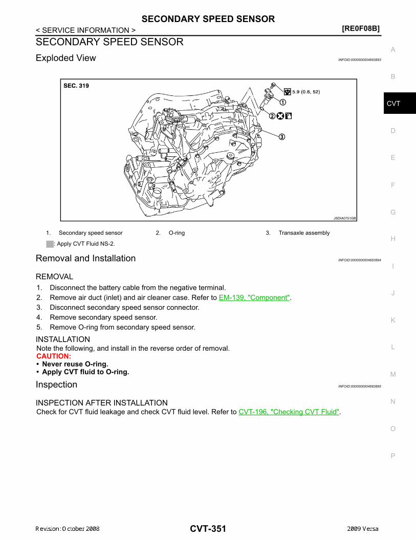
SECONDARY SPEED SENSOR[RE0F08B]
D
E
F
G
H
I
J
K
L
M
A
B
VT
N
O
P
< SERVICE INFORMATION >
C
SECONDARY SPEED SENSORExploded View INFOID:0000000004683893
Removal and Installation INFOID:0000000004683894
REMOVAL1. Disconnect the battery cable from the negative terminal.2. Remove air duct (inlet) and air cleaner case. Refer to EM-139, "Component".3. Disconnect secondary speed sensor connector.4. Remove secondary speed sensor.5. Remove O-ring from secondary speed sensor.
INSTALLATIONNote the following, and install in the reverse order of removal.CAUTION:• Never reuse O-ring.• Apply CVT fluid to O-ring.
Inspection INFOID:0000000004683895
INSPECTION AFTER INSTALLATIONCheck for CVT fluid leakage and check CVT fluid level. Refer to CVT-196, "Checking CVT Fluid".
1. Secondary speed sensor 2. O-ring 3. Transaxle assembly
: Apply CVT Fluid NS-2.
JSDIA0751GB
CVT-351

[RE0F08B]AIR BREATHER HOSE
< SERVICE INFORMATION >AIR BREATHER HOSERemoval and Installation INFOID:0000000004305822
REMOVAL1. Remove air duct (front), air duct (inlet) and air cleaner case. Refer to EM-139.2. Remove air breather hose.
INSTALLATIONInstallation is in the reverse order of removal.CAUTION:Make sure air breather hose is not collapsed or blocked due to folding or bending when installed.NOTE:• Install the air breather hose (1) to the air breather tube (2) so that
the paint mark (A) faces upward. Also make sure the air breatherhose end is pushed up to the tube bend portion.
• When installing air breather hose (1) to air duct and air cleanercase, make sure to fully insert the hose clips.
1. Air cleaner case 2. Air duct 3. Clip4. Air breather hose 5. Air breather tube 6. CVT
WCIA0612E
WCIA0613E
CVT-352

DIFFERENTIAL SIDE OIL SEAL[RE0F08B]
D
E
F
G
H
I
J
K
L
M
A
B
VT
N
O
P
< SERVICE INFORMATION >
C
DIFFERENTIAL SIDE OIL SEALRemoval and Installation INFOID:0000000004305823
COMPONENTS
REMOVAL1. Remove drive shaft assembly. Refer to FAX-9.2. Remove differential side oil seal using a suitable tool.
CAUTION:Do not scratch transaxle case or converter housing.
INSTALLATION1. Drive the new differential side oil seal into the transaxle case
side (B) and converter housing side (C) until it is flush usingTool.
Unit: mm (in)
CAUTION:• Do not reuse differential side oil seals.• Apply specified NISSAN CVT fluid to side oil seals.
2. Install drive shaft assembly. Refer to FAX-9.3. Check CVT fluid level and leakage. Refer to CVT-196, "Checking CVT Fluid".
1. CVT 2. Differential side oil seal : Apply CVT Fluid NS-2.
WCIA0610E
SCIA2412E
Tool number : — (J-47244): ST33400001 (J-47005)
Dimensions (A) 0±0.5 (0±0.020)
WCIA0611E
CVT-353

[RE0F08B]TRANSAXLE ASSEMBLY
< SERVICE INFORMATION >TRANSAXLE ASSEMBLYRemoval and Installation INFOID:0000000004305824
COMPONENTS
REMOVAL1. Remove the engine and transaxle as an assembly. Refer to EM-195, "Removal and Installation".2. Disconnect the primary speed sensor (A) and the secondary
speed sensor connector (B) and CVT unit connector (C). Referto CVT-191, "Removal and Installation Procedure for CVT UnitConnector".
3. Remove the harness from the transaxle.
1. CVT fluid level gauge 2. CVT fluid charging pipe 3. O-ring4. Copper washer 5. Fluid cooler tube 6. Transaxle assembly7. Engine mounting bracket (LH) 8. Air breather hose A. Refer to "INSTALLATION".
WCIA0614E
AWDIA0661GB
CVT-354

TRANSAXLE ASSEMBLY[RE0F08B]
D
E
F
G
H
I
J
K
L
M
A
B
VT
N
O
P
< SERVICE INFORMATION >
C
4. Remove the four drive plate to torque converter nuts.NOTE:Rotate the crankshaft clockwise as viewed from front of enginefor access to drive plate to torque converter nuts.
5. Put matching marks on the drive plate and torque converter alignment stud.CAUTION:For matching marks, use paint. Never damage the drive plate or torque converter.
6. Remove the transaxle to engine and engine to transaxle bolts.7. Separate the transaxle from the engine.8. If necessary, remove the following from the transaxle:
• CVT fluid charging pipe• Engine mounting bracket (LH)• Fluid cooler tubes• Air breather hose• Any necessary brackets
INSTALLATIONInstallation is in the reverse order of removal.CAUTION:• When replacing an engine or transmission you must make sure any dowels are installed correctly
during re-assembly.• Improper alignment caused by missing dowels may cause vibration, oil leaks or breakage of drive
train components.• Do not reuse O-rings and copper washers.• When turning crankshaft, turn it clockwise as viewed from the front of the engine.• When tightening the nuts for the torque converter while securing the crankshaft pulley bolt, be sure
to confirm the tightening torque of the crankshaft pulley bolt. Refer to EM-160.• After converter is installed to drive plate, rotate crankshaft several turns to check that transaxle
rotates freely without binding.• When installing the torque converter to the transaxle measure dis-
tance A.
WCIA0616E
Distance A: 14.4 mm (0.57 in) or more
WCIA0617E
CVT-355

[RE0F08B]TRANSAXLE ASSEMBLY
< SERVICE INFORMATION >• When installing the cooler outlet tube (1) to the transaxle assembly
(2), align the cooler tube bracket (A) against the transaxle asshown.
• When installing the transaxle to the engine, align the matching mark on the drive plate with the matchingmark on the torque converter alignment stud.
• When securing the transaxle to the engine, attach the bolts inaccordance with the following standard.
• When installing the drive plate to torque converter nuts, tightenthem temporarily. Then tighten the nuts to the specified torque.
• After completing installation check for fluid level, fluid leakage, and the positions of CVT. Refer to CVT-196,"Checking CVT Fluid", CVT-345, "Adjustment of CVT Position" and CVT-345, "Checking of CVT Position".
• When replacing the CVT assembly, erase EEP ROM in TCM. Refer to CVT-190, "Service After ReplacingTCM and Transaxle Assembly".
WCIA0618E
Bolt No. 1 (Transaxle to engine) 2 (Engine to transaxle)
Number of bolts 2 7
Bolt length “A” mm (in) 55 (2.17) 50 (1.97)
Tightening torqueN·m (kg-m, ft-lb) 62 (6.3, 46)
WCIA0619E
Converter nuts: : 51 N·m (5.2 kg-m, 38 ft-lb)
WCIA0616E
CVT-356

SERVICE DATA AND SPECIFICATIONS (SDS)[RE0F08B]
D
E
F
G
H
I
J
K
L
M
A
B
VT
N
O
P
< SERVICE INFORMATION >
C
SERVICE DATA AND SPECIFICATIONS (SDS)General Specification INFOID:0000000004305825
*1: Refer to MA-14, "Fluids and Lubricants" .
Vehicle Speed When Shifting Gears INFOID:0000000004305826
Numerical value data are reference values.
CAUTION:Lock-up clutch is engaged when vehicle speed is approximately 18 km/h (11 MPH) to 90 km/h (56 MPH).
Stall Speed INFOID:0000000004305827
Line Pressure INFOID:0000000004305828
Applied model MR18DE engine
CVT model RE0F08B
CVT assembly Model code number 1XC6C
Transmission gear ratio
“D” position Variable
Reverse 2.689
Final drive 5.473
Recommended fluid NISSAN CVT Fluid NS-2*1
Fluid capacity 7.4 liter (7-7/8 US qt, 6-1/2 Imp qt)
CAUTION:• Use only Genuine NISSAN CVT Fluid NS-2. Do not mix with other fluid.• Using CVT fluid other than Genuine NISSAN CVT Fluid NS-2 will deteriorate in driveability and CVT durability, and may dam-
age the CVT, which is not covered by the warranty.
Engine type Throttle position Shift patternEngine speed (rpm)
At 40 km/h (25 MPH) At 60 km/h (37 MPH)
MR18DE
8/8“D” position
Overdrive-off mode“L” position
3,600 - 4,500 4,400 - 5,300
2/8
“D” position 1,300 - 3,100 1,400 - 3,500
Overdrive-off mode 2,200 - 3,000 2,800 - 3,600
“L” position 3,100 - 4,000 3,800 - 4,700
Stall speed 2,600 - 3,150 rpm
Engine speed Line pressure kPa (kg/cm2 , psi)
“R”, “D” and “L” positions
At idle 650 (6.63, 94.3)
At stall 4,250 (43.35, 616.3)
CVT-357

[RE0F08B]SERVICE DATA AND SPECIFICATIONS (SDS)
< SERVICE INFORMATION >Solenoid Valves INFOID:0000000004305829
CVT Fluid Temperature Sensor INFOID:0000000004305830
Primary Speed Sensor INFOID:0000000004305831
Secondary Speed Sensor INFOID:0000000004305832
Removal and Installation INFOID:0000000004305833
Name Resistance (Approx.) Terminal
Pressure control solenoid valve B (secondary pressure solenoid valve)
3 - 9 Ω
3
Pressure control solenoid valve A (line pressure solenoid valve) 2
Torque converter clutch solenoid valve 12
Lock-up select solenoid valve 6 - 19Ω 13
Name Condition CONSULT-III “DATA MONITOR” (Approx.) Resistance (Approx.)
ATF TEMP SEN20°C (68°F) 2.0 V 6.5 kΩ
80°C (176°F) 1.0 V 0.9 kΩ
Name Condition Data (Approx.)
Primary speed sensor When driving [“L” position, 20 km/h (12 MPH)]. 1275 Hz
Name Condition Data (Approx.)
Secondary speed sensor When driving [“D” position, 20 km/h (12 MPH)]. 570 Hz
Distance between end of converter housing and torque converter 14.4 mm (0.57 in) or more
CVT-358