transmission switches - inertiaworks · armorgalv® ag3000 (thermal diffusion galvanizing) ferrous...
TRANSCRIPT
transmIssIon swItches
Inertia Engineering & Machine Works, Inc.6665 Hardaway Road, Stockton CA 95215
Tel: 800-791-9997 | Fax: 209-931-8186E-mail: [email protected]
CAT1
7011
9I
© 20
17 I
nertia
Eng
ineer
ing &
Mac
hine W
orks
, Inc.
Prin
ted 01
/17
All r
ights
rese
rved
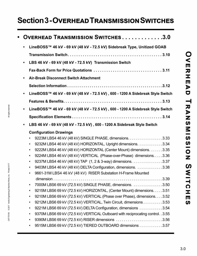
Section 3 - Overhead Transmission SwitchesO
verh
ead Tr
ansm
ission
Sw
itches
3.0
• Overhead Transmission Switches . . . . . . . . . . . . .3 .0• LineBOSS™ 46 kV - 69 kV (48 kV - 72 .5 kV) Sidebreak Type, Unitized GOAB
Transmission Switch . . . . . . . . . . . . . . . . . . . . . . . . . . . . . . . . . . . . . . . . . . . . 3 .10
• LBS 46 kV - 69 kV (48 kV - 72 .5 kV) Transmission Switch
Fax-Back Form for Price Quotations . . . . . . . . . . . . . . . . . . . . . . . . . . . . . . . . 3 .11
• Air-Break Disconnect Switch Attachment
Selection Information . . . . . . . . . . . . . . . . . . . . . . . . . . . . . . . . . . . . . . . . . . . . . . .3 .12
• LineBOSS™ 46 kV - 69 kV (48 kV - 72 .5 kV) , 600 - 1200 A Sidebreak Style Switch
Features & Benefits . . . . . . . . . . . . . . . . . . . . . . . . . . . . . . . . . . . . . . . . . . . . . . 3 .13
• LineBOSS™ 46 kV - 69 kV (48 kV - 72 .5 kV) , 600 - 1200 A Sidebreak Style Switch
Specification Elements . . . . . . . . . . . . . . . . . . . . . . . . . . . . . . . . . . . . . . . . . . 3 .14
• LBS 46 kV - 69 kV (48 kV - 72 .5 kV) , 600 - 1200 A Sidebreak Style Switch
Configuration Drawings• 9223M LBS4 46 kV (48 kV) SINGLE PHASE, dimensions. . . . . . . . . . . . . . . . . .3.33• 9232M LBS4 46 kV (48 kV) HORIZONTAL, Upright dimensions. . . . . . . . . . . . .3.34• 9222M LBS4 46 kV (48 kV) HORIZONTAL (Center Mount) dimensions. . . . . . .3.35• 9224M LBS4 46 kV (48 kV) VERTICAL (Phase-over-Phase) dimensions. . . . .3.36• 9237M LBS4 46 kV (48 kV) TAP (1, 2 & 3-way) dimensions. . . . . . . . . . . . . . . .3.37• 9403M LBS4 46 kV (48 kV) DELTA Configuration, dimensions. . . . . . . . . . . . . .3.38• 9661-31M LBS4 46 kV (48 kV) RISER Substation H-Frame Mounted
dimension . . . . . . . . . . . . . . . . . . . . . . . . . . . . . . . . . . . . . . . . . . . . . . . . . . . . . . . .3.39• 7000M LBS6 69 kV (72.5 kV) SINGLE PHASE, dimensions. . . . . . . . . . . . . . . .3.50• 9215M LBS6 69 kV (72.5 kV) HORIZONTAL, (Center Mount) dimensions. . . . .3.51• 9210M LBS6 69 kV (72.5 kV) VERTICAL (Phase over Phase), dimensions. . . .3.52• 9212M LBS6 69 kV (72.5 kV) VERTICAL, Twin Circuit, dimensions . . . . . . . . . .3.53• 9221M LBS6 69 kV (72.5 kV) DELTA Configuration, dimensions . . . . . . . . . . . .3.54• 9370M LBS6 69 kV (72.5 kV) VERTICAL Outboard with reciprocating control. .3.55• 9390M LBS6 69 kV (72.5 kV) RISER dimensions . . . . . . . . . . . . . . . . . . . . . . . .3.56• 9515M LBS6 69 kV (72.5 kV) TIERED OUTBOARD dimensions . . . . . . . . . . . .3.57

CAT0
4093
0H
© 20
16 I
nertia
Eng
ineer
ing &
Mac
hine W
orks
, Inc.
Prin
ted X
X/XX
A
ll righ
ts re
serve
d
INERTIA Engineering & Machine Works, Inc. Tel: 800-791-9997 | Fax: 209-931-8186 6665 Hardaway Road • Stockton, CA 95215 E-mail: [email protected]
INERTIA Engineering and Machine Works, Inc. adapted the industry leading design features of its distribution class switches, to produce a high quality, cost effective, unitized sidebreak style transmission switch.
The ease of installation that unitized distribution class switches provide is now available for transmission class switches. The phase units are shipped as completely factory assembled and adjusted units. The actual configuration is delivered fully unitized or modularized for fast, simple and easy field installation.
The LineBOSS™ 46 kV and 69 kV sidebreak switches are the lowest “cost to own” switches available today. Fully unitized or modular switches are hung on the pole in hours, not days. These switches also provide lower operating costs. Unbalanced conductor load or seasonal temperature changes can create line sag leading to contact misalignment on other style switches. This maintenance headache is eliminated by the LineBOSS™ sidebreak switch. Custom phase bases are available for installation on a wide variety of structures.
STANDARD FEATURES
• Unitized or modular construction on aluminum or steel cros-sarms for fast and easy installations.
• Factory adjusted, ready to mount with minimal, if any, field assembly required.
• Available with silicone (std.) or porcelain insulators. • Reverse loop, silver plated copper jaw contacts.• Maintenance-free, sealed, stainless steel ball bearings.• Meets all applicable NEMA and ANSI standards.• All ferrous components are hot dip galvanized. • Tinned copper two-hole and four-hole terminal pads• TDG (Thermal Diffusion Galvanized) coated ferrous
components available for increased corrosion resistance.
STANDARD CONFIGURATIONS • Horizontal, Center Mount• Vertical, Phase over phase• Delta, Triangular/Pole Top• Twin Circuit• Tap Switch: 1, 2, and 3-way• Vertical, Tiered Outboard
SPECIFICATIONSVoltage Class: 46 kV (48 kV max.) & 69 kV (72.5 kV max.)Current Class: 600, 900 and 1200 A, continuous Momentary current: 600 A: 40,000 A-rms, 10 cycles 25,000 A-rms, 3 seconds 900 A: 51,000 A-rms, 10 cycles 32,000 A-rms, 3 seconds 1200 A: 70,000 A-rms, 10 cycles 44,000 A-rms, 3 seconds
Continuous current ratings tested to IEEE C37.32-1996
INTERRUPTER/LOADBREAK RATINGS (Maximum)
High Speed Break Ratings: Voltage Cable Charging Magnetizing 46 kV 18 A-rms 18 A-rms 69 kV 15 A-rms 15 A-rms
LineBOSS™46 kV - 69 kV (48 kV - 72 .5 kV)
Sidebreak Type, Unitized GOAB Transmission Switch
3.10
Vacuum Bottle Interrupters AmpVacTM V V4 V7Voltage Class 15.5 kV, 25 kV, 38 kV* 48.0 kV 72.5 kVInterrupting Current 2000 A 2000 A 2000 AParallel Break Current 1500 A 2000 A 2000 ACable Charging Current 40 A 10 A 10 AMagnetizing Current 21 A 70 A 70 A
• Horizontal, Underarm• In-Line Tap• Riser Switch• Horizontal, Pole Top• Vertical Twin Circuit• Avian/Wildlife Protection
CAT0
4093
0H
© 20
16 I
nertia
Eng
ineer
ing &
Mac
hine W
orks
, Inc.
Prin
ted X
X/XX
A
ll righ
ts re
serve
d
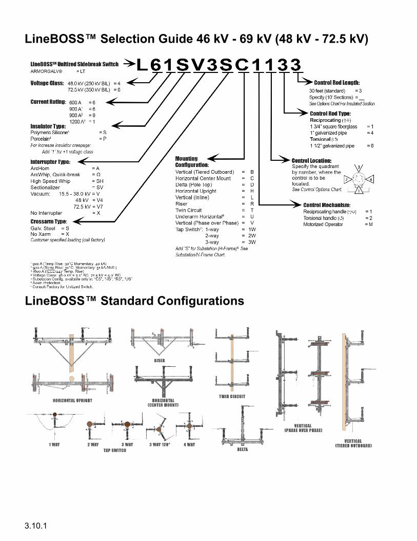
LineBOSS™ Selection Guide 46 kV - 69 kV (48 kV - 72 .5 kV)
LineBOSS™ Standard Configurations
3.10.1

CAT0
4093
0H
© 20
16 I
nertia
Eng
ineer
ing &
Mac
hine W
orks
, Inc.
Prin
ted X
X/XX
A
ll righ
ts re
serve
d
INERTIA Engineering & Machine Works, Inc. Tel: 800-791-9997 | Fax: 209-931-8186 6665 Hardaway Road • Stockton, CA 95215 E-mail: [email protected]
LineBOSS™48 kV - 72 .5 kV Transmission Switch
Request For QuotationE-MAIL: sales@inertiaworks .com | FAX: (209) 931-8186
________________________________________________Company Name
________________________________________________Address 1
________________________________________________Address 2
________________________________________________City State Zip code
______________________________________Contact Name
______________________________________Telephone Number
______________________________________Facsimile Number
______________________________________E-mail address
Make copies of this form to transmit your switch requirements. If you have your own standard’s drawing, please fill out
the customer information and send it with this fax form.
Step 1. Voltage Class _______kV Continuous Current Rating (ANSI)1: ___________Amps
Step 2. Insulator Type: Silicone Porcelain
Step 3. Interrupter Type: ArcHorn ArcWhip Hi-speed Break AmpVac ‘V’ V4 V7
Step 4. Select Crossarm Type: Galvanized Steel Aluminum
Step 5. Select the configuration (circle one):
Step 6. Select Spacing:
Standard Custom (Fill in Spacing Dimensions below using configurations in Step 5.)
A” ________ “B” ________ “C” ________ “D” ________ “E”________
Step 7. Select the control mechanism:
Reciprocating () Torsional () Clockwise or Counterclockwise to open; viewed looking down on the handle.
Step 8. Select the control mechanism quadrant (see fig. 1): ________
1 LineBOSS™ switches are ANSI rated switches. The LineBOSS™ Lx6xxxxx is rated 600 Amps continuous current per the ANSI C37.30 temperature rise test requirements, and for 900 Amp continuous current per the IEEE 1247 temperature rise test requirements. The LineBOSS™ Lx9xxxxx is rated 900 Amps continuous current per the ANSI C37.30 temperature rise test requirements. The LineBOSS™ Lx1xxxxx is rated 1200 Amps continuous current per the ANSI C37.30 temperature rise test requirements. Momentary current ratings (10 cycle) are: 600 A (ANSI C37.30) = 40 kA 900 A (ANSI C37.30) = 51 kA 1200 A(ANSI C37.30) = 70 kA
3.11
Figure 1: Control Quadrants
CAT0
4093
0H
© 20
16 I
nertia
Eng
ineer
ing &
Mac
hine W
orks
, Inc.
Prin
ted X
X/XX
A
ll righ
ts re
serve
d
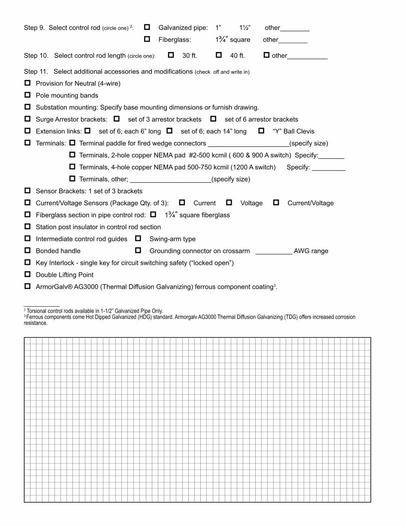
Step 9. Select control rod (circle one) 2: Galvanized pipe: 1” 1½” other________
Fiberglass: 1¾” square other________
Step 10. Select control rod length (circle one): 30 ft. 40 ft. other___________
Step 11. Select additional accessories and modifications (check off and write in)
Provision for Neutral (4-wire)
Pole mounting bands
Substation mounting: Specify base mounting dimensions or furnish drawing.
Surge Arrestor brackets: set of 3 arrestor brackets set of 6 arrestor brackets
Extension links: set of 6; each 6” long set of 6; each 14” long “Y” Ball Clevis
Terminals: Terminal paddle for fired wedge connectors ______________________(specify size)
Terminals, 2-hole copper NEMA pad #2-500 kcmil ( 600 & 900 A switch) Specify:_______
Terminals, 4-hole copper NEMA pad 500-750 kcmil (1200 A switch) Specify: _________
Terminals, other; ______________________(specify size)
Sensor Brackets: 1 set of 3 brackets
Current/Voltage Sensors (Package Qty. of 3): Current Voltage Current/Voltage
Fiberglass section in pipe control rod: 1¾” square fiberglass
Station post insulator in control rod section
Intermediate control rod guides Swing-arm type
Bonded handle Grounding connector on crossarm __________ AWG range
Key Interlock - single key for circuit switching safety (“locked open”)
Double Lifting Point
ArmorGalv® AG3000 (Thermal Diffusion Galvanizing) ferrous component coating3.
2 Torsional control rods available in 1-1/2” Galvanized Pipe Only.3 Ferrous components come Hot Dipped Galvanized (HDG) standard. Armorgalv AG3000 Thermal Diffusion Galvanizing (TDG) offers increased corrosion resistance.
3.11.1
CAT0
4093
0H
© 20
16 I
nertia
Eng
ineer
ing &
Mac
hine W
orks
, Inc.
Prin
ted X
X/XX
A
ll righ
ts re
serve
d
INERTIA Engineering & Machine Works, Inc. Tel: 800-791-9997 | Fax: 209-931-8186 6665 Hardaway Road • Stockton, CA 95215 E-mail: [email protected]
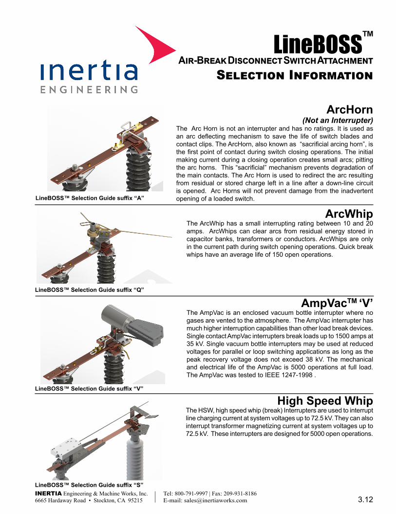
ArcHorn (Not an Interrupter)
The Arc Horn is not an interrupter and has no ratings. It is used as an arc deflecting mechanism to save the life of switch blades and contact clips. The ArcHorn, also known as “sacrificial arcing horn”, is the first point of contact during switch closing operations. The initial making current during a closing operation creates small arcs; pitting the arc horns. This “sacrificial” mechanism prevents degradation of the main contacts. The Arc Horn is used to redirect the arc resulting from residual or stored charge left in a line after a down-line circuit is opened. Arc Horns will not prevent damage from the inadvertent opening of a loaded switch.
ArcWhipThe ArcWhip has a small interrupting rating between 10 and 20 amps. ArcWhips can clear arcs from residual energy stored in capacitor banks, transformers or conductors. ArcWhips are only in the current path during switch opening operations. Quick break whips have an average life of 150 open operations.
AmpVacTM ‘V’The AmpVac is an enclosed vacuum bottle interrupter where no gases are vented to the atmosphere. The AmpVac interrupter has much higher interruption capabilities than other load break devices. Single contact AmpVac interrupters break loads up to 1500 amps at 35 kV. Single vacuum bottle interrupters may be used at reduced voltages for parallel or loop switching applications as long as the peak recovery voltage does not exceed 38 kV. The mechanical and electrical life of the AmpVac is 5000 operations at full load. The AmpVac was tested to IEEE 1247-1998 .
LineBOSS™ Selection Guide suffix “A”
LineBOSS™ Selection Guide suffix “V”
3.12
LineBOSS™Air-Break Disconnect Switch Attachment
Selection Information
LineBOSS™ Selection Guide suffix “Q”
High Speed WhipThe HSW, high speed whip (break) Interrupters are used to interrupt line charging current at system voltages up to 72.5 kV. They can also interrupt transformer magnetizing current at system voltages up to 72.5 kV. These interrupters are designed for 5000 open operations.
LineBOSS™ Selection Guide suffix “S”
CAT0
4093
0H
© 20
16 I
nertia
Eng
ineer
ing &
Mac
hine W
orks
, Inc.
Prin
ted X
X/XX
A
ll righ
ts re
serve
d
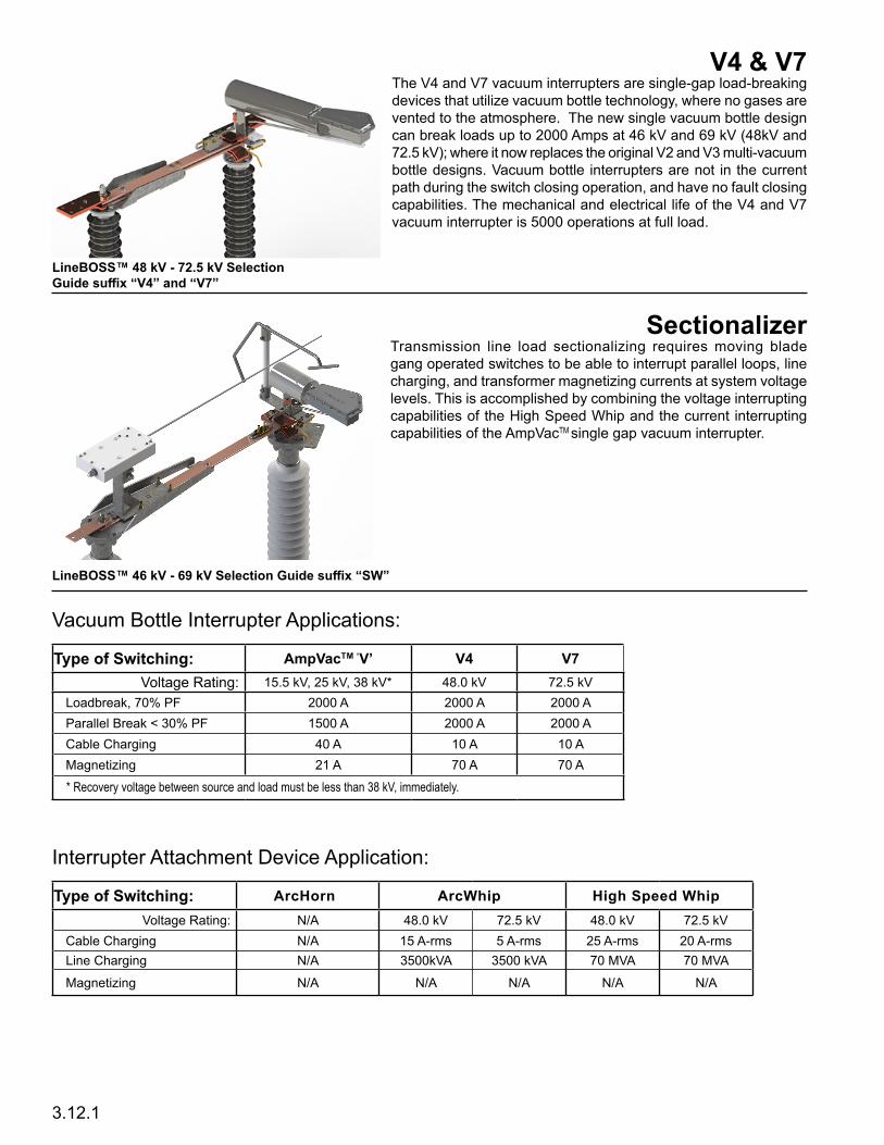
V4 & V7The V4 and V7 vacuum interrupters are single-gap load-breaking devices that utilize vacuum bottle technology, where no gases are vented to the atmosphere. The new single vacuum bottle design can break loads up to 2000 Amps at 46 kV and 69 kV (48kV and 72.5 kV); where it now replaces the original V2 and V3 multi-vacuum bottle designs. Vacuum bottle interrupters are not in the current path during the switch closing operation, and have no fault closing capabilities. The mechanical and electrical life of the V4 and V7 vacuum interrupter is 5000 operations at full load.
SectionalizerTransmission line load sectionalizing requires moving blade gang operated switches to be able to interrupt parallel loops, line charging, and transformer magnetizing currents at system voltage levels. This is accomplished by combining the voltage interrupting capabilities of the High Speed Whip and the current interrupting capabilities of the AmpVacTM single gap vacuum interrupter.
LineBOSS™ 48 kV - 72 .5 kV Selection Guide suffix “V4” and “V7”
3.12.1
Vacuum Bottle Interrupter Applications:
Type of Switching: AmpVacTM ‘V’ V4 V7Voltage Rating: 15.5 kV, 25 kV, 38 kV* 48.0 kV 72.5 kV
Loadbreak, 70% PF 2000 A 2000 A 2000 AParallel Break < 30% PF 1500 A 2000 A 2000 ACable Charging 40 A 10 A 10 AMagnetizing 21 A 70 A 70 A * Recovery voltage between source and load must be less than 38 kV, immediately.
Interrupter Attachment Device Application:
Type of Switching: ArcHorn ArcWhip High Speed WhipVoltage Rating: N/A 48.0 kV 72.5 kV 48.0 kV 72.5 kV
Cable Charging N/A 15 A-rms 5 A-rms 25 A-rms 20 A-rmsLine Charging N/A 3500kVA 3500 kVA 70 MVA 70 MVA
Magnetizing N/A N/A N/A N/A N/A
LineBOSS™ 46 kV - 69 kV Selection Guide suffix “SW”

CAT0
4093
0H
© 20
16 I
nertia
Eng
ineer
ing &
Mac
hine W
orks
, Inc.
Prin
ted X
X/XX
A
ll righ
ts re
serve
d
INERTIA Engineering & Machine Works, Inc. Tel: 800-791-9997 | Fax: 209-931-8186 6665 Hardaway Road • Stockton, CA 95215 E-mail: [email protected]
LineBOSS™46 kV & 69 kV (48 kV & 72 .5 kV), 600 - 1200 A
Sidebreak Style SwitchFeatures and Benefits
Inertia’s unitized transmission switches install with the speed and ease of distribution switches and provide years of maintenance-free operation. Featuring the lowest installed, lowest operating cost switch comprised of quality components to ensure longer service-life.
Busbar grade copper contact components .
Inertia uses busbar grade copper contact components as they are structur-ally and electrically superior to cast contact materials. Cast aluminum and copper bronze contact castings are 34-36% conductive and often contain unseen surface irregularities and voids that create ‘hot spots’. Busbar grade C110 copper is 99% conductive and is many times smoother to provide better connection surfaces and is not subject to porosity. Benefit:Reducedoperatingcostduetoacoolerrunningswitch.Longerservice life with reduced energy loss.
FEATURES
ANSI TR2xx series, 3” (48kV) & 5”(72 .5kV) bolt circle station post insulators are provided in silicone or porcelain .
TheLBSswitchesareofferedwithsiliconeorporcelain,threeinch(3”)andfiveinch (5”) bolt circle station post insulators. Silicone insulators are standard, with porcelain available as a lower cost alternate. Benefit:Siliconeinsulatedswitchesarelighterandeasiertoinstallwithmin-imal chance of damage when un-crating and erecting. Porcelain insulators provide a lower cost option.
The rotating insulators pivot on double sealed stainless steel ball bearings at both the top and bottom of the phase base providing smooth maintenance-free operation of the switch throughout its life. Benefit:Totaloperatingcostoftheswitchisreducedaslesssitevisitsarerequired for maintenance.
Interlocking phase base design with through-hole mounting bolts .
Unitized/Modular Switches
The LineBOSS™ 46 kV and 69 kV switches come from the factory with eachphaseunitcompletelyunitizedandadjusted.Whentheswitchconfig-uration calls for partial assembly, the LBS switch is broken down into easily assembledmodules.Thelocationsofthemodulesarefixed,requiringverylittle, if any, adjustment.Benefit:Greatly reduced installed costwithminimal field assembly andadjustment of the switch.
Sealed stainless steel ball bearings on rotating stacks
The LBS 46 kV and 69 kV phase units have an interlocking design that se-curely clamps and locates each phase unit on the crossarm. Secure phase bases result in minimal movement over the life of the switch. Adjustments to the switch are virtually eliminated. The through-bolt fastening assures that userspecifiedphasespacingismetwithoutadditionalfieldmeasurementsor adjustments.Benefit:Reducedinstalledcostduetominimalassembly Reduced maintenance cost through secure clamping
Stainless steel/ brass bearings in the bellcrank
Bearings in the bellcrank mechanism reduce the force required to operate the switch and eliminate corrosion caused by plated metal-to-metal abrasion and wear. Benefit: The ease of operation reduces risk of injury to personnel operating the switch and also translates into greater switch life.
BENEFITS
3.13
CAT0
4093
0H
© 20
16 I
nertia
Eng
ineer
ing &
Mac
hine W
orks
, Inc.
Prin
ted X
X/XX
A
ll righ
ts re
serve
d
INERTIA Engineering & Machine Works, Inc. Tel: 800-791-9997 | Fax: 209-931-8186 6665 Hardaway Road • Stockton, CA 95215 E-mail: [email protected]
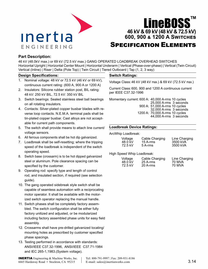
Design Specifications:1. Nominal voltage: 48 kV or 72.5 kV (46 kV or 69 kV),
continuous current rating: (600 A, 900 A or 1200 A)2. Insulators: Silicone rubber station post, BIL rating:
48 kV: 250 kV BIL, 72.5 kV: 350 kV BIL3. Switch bearings: Sealed stainless steel ball bearings
on all rotating insulators.4. Contacts: Silver-plated copper busbar blades with re-
verse loop contacts. N.E.M.A. terminal pads shall be tin-plated copper busbar. Cast alloys are not accept-able for current path components.
5. The switch shall provide means to attach line current/voltage sensors.
6. All ferrous components shall be hot dip galvanized.7. Loadbreak shall be self-resetting; where the tripping
speed of the loadbreak is independent of the switch operating speed.
8. Switch base (crossarm) is to be hot dipped galvanized steel or aluminum. Pole clearance spacing can be specified by the customer.
9. Operating rod: specify type and length of control rod, and insulated section, if required (see selection guide).
10. The gang operated sidebreak style switch shall be capable of seamless automation with a reciprocating motor operator. It shall be available with the motor-ized switch operator replacing the manual handle.
11. Switch phases shall be completely factory assem-bled. The switch configuration shall be either fully factory unitized and adjusted, or be modularized including factory assembled phase units for easy field assembly.
12. Crossarms shall have pre-drilled galvanized locating/mounting holes as prescribed by customer specified phase spacings.
13. Testing performed in accordance with standards: ANSI/IEEE C37.32-1996, ANSI/IEEE C37.71-1984 and IEC 265-1,1983.(System voltage).
Switch Ratings:Voltage Class: 46 kV (48 kV max.) & 69 kV (72.5 kV max.)
Current Class: 600, 900 and 1200 A continuous current per IEEE C37.32-1996
Momentary current: 600 A: 40,000 A-rms 10 cycles 25,000 A-rms 3 seconds 900 A: 51,000 A-rms 10 cycles 32,000 A-rms 3 seconds 1200 A: 70,000 A-rms 10 cycles 44,000 A-rms 3 seconds
Loadbreak Device Ratings:ArcWhip Loadbreak: Voltage Cable Charging Line Charging 48.0 kV 15 A-rms 3500 kVA 72.5 kV 5 A-rms 3500 kVA
High Speed Whip Loadbreak: Voltage Cable Charging Line Charging 48.0 kV 25 A-rms 70 MVA 72.5 kV 20 A-rms 70 MVA
LineBOSS™46 kV & 69 kV (48 kV & 72 .5 kV)
600, 900 & 1200 A SwitchesSpecification Elements
Part Description:46 kV (48.0kV max.) or 69 kV (72.5 kV max.) GANG OPERATED LOADBREAK OVERHEAD SWITCHES Horizontal Upright | Horizontal Center Mount | Horizontal Underarm | Vertical (Phase-over-phase) | Vertical (Twin Circuit) Vertical (Inline) | Riser | Delta (Pole Top) | Twin Circuit | Tiered Outboard | Tap (1, 2, 3 way)
3.14
CAT1
7011
9I
© 20
17 I
nertia
Eng
ineer
ing &
Mac
hine W
orks
, Inc.
Prin
ted 01
/17
All r
ights
rese
rved
Description:
Drawing No.: Revision:
This drawing is for illustrative purposes only and therefore; may, or may not reflect the current revision of this drawing. Please request the current revision from the factory upon quote.
INERTIA Engineering & Machine Works, Inc. Tel: 800-791-9997 | Fax: 209-931-8186 6665 Hardaway Road • Stockton, CA 95215 E-mail: [email protected]
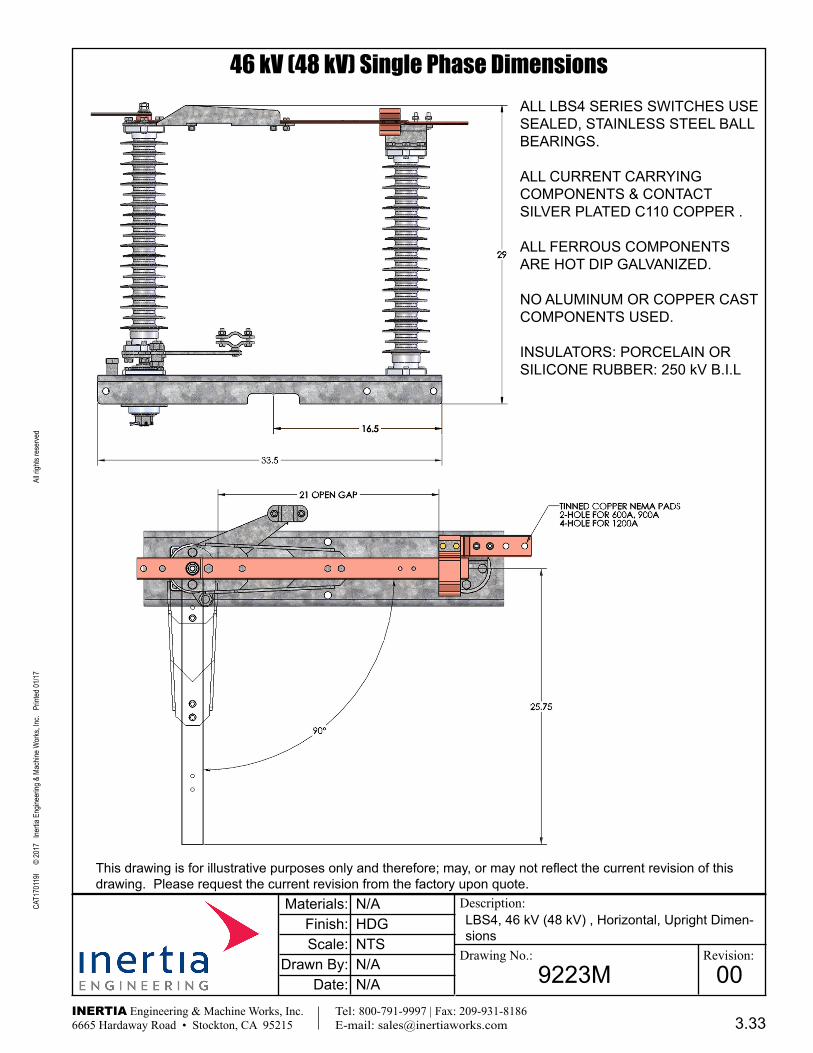
46 kV (48 kV) Single Phase Dimensions
9223M 00
Materials:Finish:Scale:
Drawn By:Date:
N/A
N/A
HDGNTS
N/A
LBS4, 46 kV (48 kV) , Horizontal, Upright Dimen-sions
ALL LBS4 SERIES SWITCHES USE SEALED, STAINLESS STEEL BALL BEARINGS.
ALL CURRENT CARRYING COMPONENTS & CONTACT SILVER PLATED C110 COPPER .
ALL FERROUS COMPONENTS ARE HOT DIP GALVANIZED.
NO ALUMINUM OR COPPER CAST COMPONENTS USED.
INSULATORS: PORCELAIN OR SILICONE RUBBER: 250 kV B.I.L
3.33
CAT1
7011
9I
© 20
17 I
nertia
Eng
ineer
ing &
Mac
hine W
orks
, Inc.
Prin
ted 01
/17
All r
ights
rese
rved
Description:
Drawing No.: Revision:
This drawing is for illustrative purposes only and therefore; may, or may not reflect the current revision of this drawing. Please request the current revision from the factory upon quote.
INERTIA Engineering & Machine Works, Inc. Tel: 800-791-9997 | Fax: 209-931-8186 6665 Hardaway Road • Stockton, CA 95215 E-mail: [email protected]
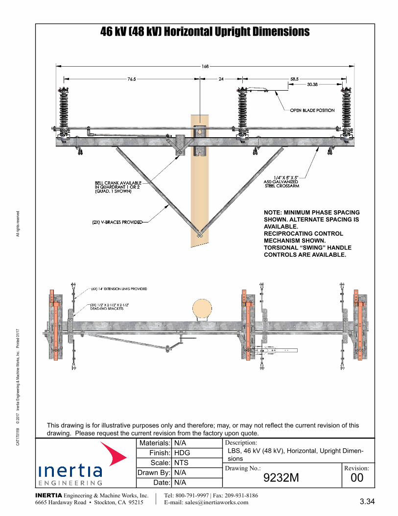
46 kV (48 kV) Horizontal Upright Dimensions
9232M 00
Materials:Finish:Scale:
Drawn By:Date:
N/A
N/A
HDGNTS
N/A
LBS, 46 kV (48 kV), Horizontal, Upright Dimen-sions
NOTE: MINIMUM PHASE SPACING SHOWN . ALTERNATE SPACING IS AVAILABLE .RECIPROCATING CONTROL MECHANISM SHOWN . TORSIONAL “SWING” HANDLE CONTROLS ARE AVAILABLE .
3.34

CAT1
7011
9I
© 20
17 I
nertia
Eng
ineer
ing &
Mac
hine W
orks
, Inc.
Prin
ted 01
/17
All r
ights
rese
rved
Description:
Drawing No.: Revision:
This drawing is for illustrative purposes only and therefore; may, or may not reflect the current revision of this drawing. Please request the current revision from the factory upon quote.
INERTIA Engineering & Machine Works, Inc. Tel: 800-791-9997 | Fax: 209-931-8186 6665 Hardaway Road • Stockton, CA 95215 E-mail: [email protected]
46 kV (48 kV) Horizontal Upright Dimensions
9222M 00
N/A
N/A
HDGNTS
N/A
LBS, 46 kV (48 kV), Horizontal (center mount), Dimensions
Materials:Finish:Scale:
Drawn By:Date:
NOTE: MINIMUM PHASE SPACING SHOWN . ALTERNATE SPACING IS AVAILABLE .RECIPROCATING CONTROL MECHANISM SHOWN . TORSIONAL “SWING” HANDLE CONTROLS ARE AVAILABLE .
3.35

CAT1
7011
9I
© 20
17 I
nertia
Eng
ineer
ing &
Mac
hine W
orks
, Inc.
Prin
ted 01
/17
All r
ights
rese
rved
Description:
Drawing No.: Revision:
This drawing is for illustrative purposes only and therefore; may, or may not reflect the current revision of this drawing. Please request the current revision from the factory upon quote.
INERTIA Engineering & Machine Works, Inc. Tel: 800-791-9997 | Fax: 209-931-8186 6665 Hardaway Road • Stockton, CA 95215 E-mail: [email protected]
46 kV (48 kV) Horizontal Upright Dimensions
9224M 00
N/A
YU
N/ANTS
12/14/16
LBS, 46 kV (48 kV), Vertical (Phase over Phase), Dimensions
Materials:Finish:Scale:
Drawn By:Date:
NOTE: MINIMUM PHASE SPACING SHOWN . ALTERNATE SPACING IS AVAILABLE .PHASE OVER PHASE (VERTICAL) SWITCHES ARE AVAILABLE WITH RECIPROCATING () CONTROL MECHANISMS ONLY .
3.36
CAT1
7011
9I
© 20
17 I
nertia
Eng
ineer
ing &
Mac
hine W
orks
, Inc.
Prin
ted 01
/17
All r
ights
rese
rved
Description:
Drawing No.: Revision:
This drawing is for illustrative purposes only and therefore; may, or may not reflect the current revision of this drawing. Please request the current revision from the factory upon quote.
INERTIA Engineering & Machine Works, Inc. Tel: 800-791-9997 | Fax: 209-931-8186 6665 Hardaway Road • Stockton, CA 95215 E-mail: [email protected]
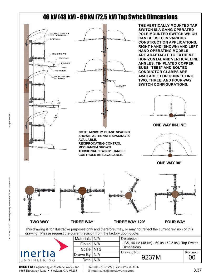
46 kV (48 kV) - 69 kV (72.5 kV) Tap Switch Dimensions
9237M 00
N/A
N/A
N/ANTS
N/A
LBS, 46 kV (48 kV) - 69 kV (72.5 kV), Tap Switch Dimensions
Materials:Finish:Scale:
Drawn By:Date:
NOTE: MINIMUM PHASE SPACING SHOWN . ALTERNATE SPACING IS AVAILABLE .RECIPROCATING CONTROL MECHANISM SHOWN . TORSIONAL “SWING” HANDLE CONTROLS ARE AVAILABLE .
THE VERTICALLY MOUNTED TAP SWITCH IS A GANG OPERATED POLE MOUNTED SWITCH WHICH CAN BE USED IN VARIOUS CONSTRUCTION APPLICATIONS . RIGHT HAND (SHOWN) AND LEFT HAND OPERATING MODELS ARE ADAPTABLE TO EXTREME HORIzONTAL AND VERTICAL LINE ANGLES . TIN PLATED COPPER BUSS “TEES” AND BOLTED CONDUCTOR CLAMPS ARE AVAILABLE FOR CONNECTING TWO, THREE, AND FOUR-WAY SWITCH CONFIGURATIONS .
ONE WAY IN-LINE
ONE WAY 90°
TWO WAY THREE WAY 120°THREE WAY FOUR WAY
3.37
CAT1
7011
9I
© 20
17 I
nertia
Eng
ineer
ing &
Mac
hine W
orks
, Inc.
Prin
ted 01
/17
All r
ights
rese
rved
Description:
Drawing No.: Revision:
This drawing is for illustrative purposes only and therefore; may, or may not reflect the current revision of this drawing. Please request the current revision from the factory upon quote.
INERTIA Engineering & Machine Works, Inc. Tel: 800-791-9997 | Fax: 209-931-8186 6665 Hardaway Road • Stockton, CA 95215 E-mail: [email protected]
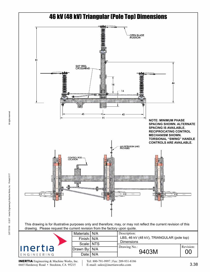
46 kV (48 kV) Triangular (Pole Top) Dimensions
9403M 00
N/A
N/A
N/ANTS
N/A
LBS, 46 kV (48 kV), TRIANGULAR (pole top) Dimensions
Materials:Finish:Scale:
Drawn By:Date:
NOTE: MINIMUM PHASE SPACING SHOWN . ALTERNATE SPACING IS AVAILABLE .RECIPROCATING CONTROL MECHANISM SHOWN . TORSIONAL “SWING” HANDLE CONTROLS ARE AVAILABLE .
3.38

CAT1
7011
9I
© 20
17 I
nertia
Eng
ineer
ing &
Mac
hine W
orks
, Inc.
Prin
ted 01
/17
All r
ights
rese
rved
Description:
Drawing No.: Revision:
This drawing is for illustrative purposes only and therefore; may, or may not reflect the current revision of this drawing. Please request the current revision from the factory upon quote.
INERTIA Engineering & Machine Works, Inc. Tel: 800-791-9997 | Fax: 209-931-8186 6665 Hardaway Road • Stockton, CA 95215 E-mail: [email protected]
46 kV (48 kV) Riser Substation H-Frame Dimensions
9661-31M 00
N/A
JN
HDGNTS
N/A
LBS4, 46 kV (48 kV), RISER Substation H-Frame Mounted, Switch Dimensions
Materials:Finish:Scale:
Drawn By:Date:
NOTE: MINIMUM PHASE SPACING SHOWN . ALTERNATE SPACING IS AVAILABLE .RECIPROCATING CONTROL MECHANISM SHOWN . TORSIONAL “SWING” HANDLE CONTROLS ARE AVAILABLE .
MINIMUM PHASE SPACING
Nominal Voltage Rating
DIM: 48 kV
A 58.5”
3.39

CAT1
7011
9I
© 20
17 I
nertia
Eng
ineer
ing &
Mac
hine W
orks
, Inc.
Prin
ted 01
/17
All r
ights
rese
rved
Description:
Drawing No.: Revision:
This drawing is for illustrative purposes only and therefore; may, or may not reflect the current revision of this drawing. Please request the current revision from the factory upon quote.
INERTIA Engineering & Machine Works, Inc. Tel: 800-791-9997 | Fax: 209-931-8186 6665 Hardaway Road • Stockton, CA 95215 E-mail: [email protected]
69 kV (72.5 kV) Single Phase Dimensions
7000M 00
N/A
YU
N/ANTS
12/19/16
LBS6 69 kV (72.5 kV) Single Phase Unit, Dimen-sions
Materials:Finish:Scale:
Drawn By:Date:
NOTE: MINIMUM PHASE SPACING SHOWN . ALTERNATE SPACING IS AVAILABLE .RECIPROCATING CONTROL MECHANISM SHOWN . TORSIONAL “SWING” HANDLE CONTROLS ARE AVAILABLE .
3.50
CAT1
7011
9I
© 20
17 I
nertia
Eng
ineer
ing &
Mac
hine W
orks
, Inc.
Prin
ted 01
/17
All r
ights
rese
rved
Description:
Drawing No.: Revision:
This drawing is for illustrative purposes only and therefore; may, or may not reflect the current revision of this drawing. Please request the current revision from the factory upon quote.
INERTIA Engineering & Machine Works, Inc. Tel: 800-791-9997 | Fax: 209-931-8186 6665 Hardaway Road • Stockton, CA 95215 E-mail: [email protected]
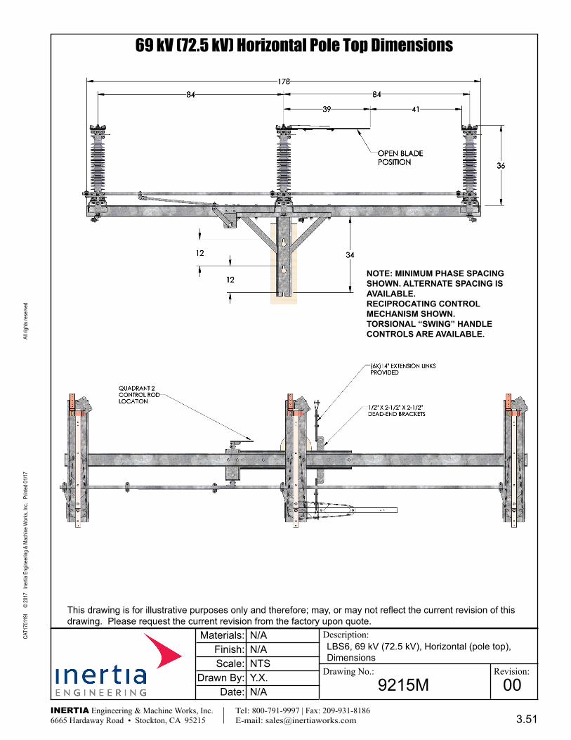
69 kV (72.5 kV) Horizontal Pole Top Dimensions
9215M 00
N/A
Y.X.
N/ANTS
N/A
LBS6, 69 kV (72.5 kV), Horizontal (pole top), Dimensions
Materials:Finish:Scale:
Drawn By:Date:
NOTE: MINIMUM PHASE SPACING SHOWN . ALTERNATE SPACING IS AVAILABLE .RECIPROCATING CONTROL MECHANISM SHOWN . TORSIONAL “SWING” HANDLE CONTROLS ARE AVAILABLE .
3.51
CAT1
7011
9I
© 20
17 I
nertia
Eng
ineer
ing &
Mac
hine W
orks
, Inc.
Prin
ted 01
/17
All r
ights
rese
rved
Description:
Drawing No.: Revision:
This drawing is for illustrative purposes only and therefore; may, or may not reflect the current revision of this drawing. Please request the current revision from the factory upon quote.
INERTIA Engineering & Machine Works, Inc. Tel: 800-791-9997 | Fax: 209-931-8186 6665 Hardaway Road • Stockton, CA 95215 E-mail: [email protected]
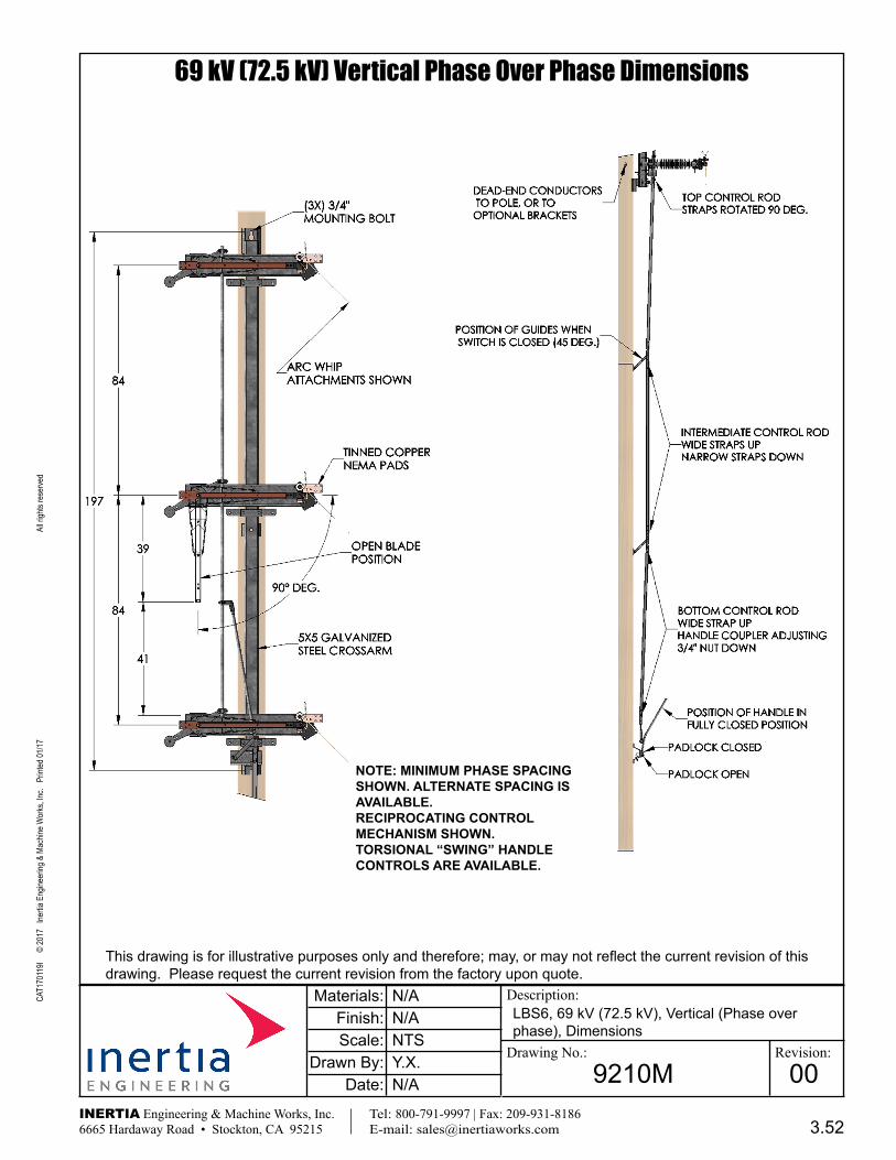
69 kV (72.5 kV) Vertical Phase Over Phase Dimensions
9210M 00
N/A
Y.X.
N/ANTS
N/A
LBS6, 69 kV (72.5 kV), Vertical (Phase over phase), Dimensions
Materials:Finish:Scale:
Drawn By:Date:
NOTE: MINIMUM PHASE SPACING SHOWN . ALTERNATE SPACING IS AVAILABLE .RECIPROCATING CONTROL MECHANISM SHOWN . TORSIONAL “SWING” HANDLE CONTROLS ARE AVAILABLE .
3.52
CAT1
7011
9I
© 20
17 I
nertia
Eng
ineer
ing &
Mac
hine W
orks
, Inc.
Prin
ted 01
/17
All r
ights
rese
rved
Description:
Drawing No.: Revision:
This drawing is for illustrative purposes only and therefore; may, or may not reflect the current revision of this drawing. Please request the current revision from the factory upon quote.
INERTIA Engineering & Machine Works, Inc. Tel: 800-791-9997 | Fax: 209-931-8186 6665 Hardaway Road • Stockton, CA 95215 E-mail: [email protected]
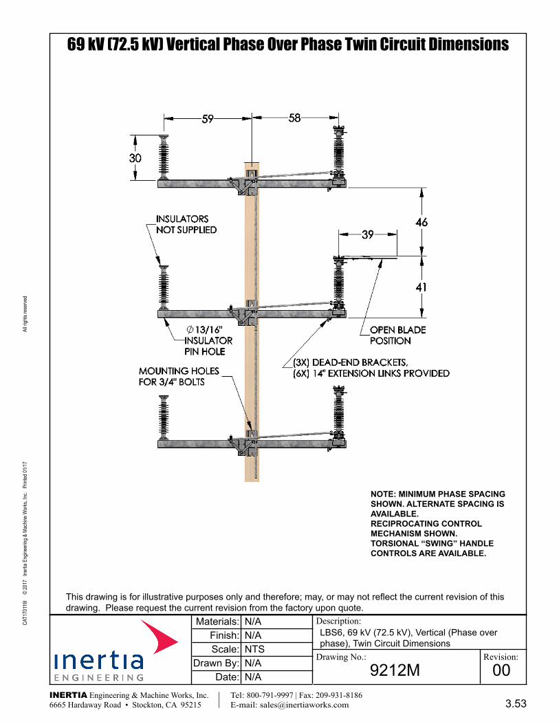
69 kV (72.5 kV) Vertical Phase Over Phase Twin Circuit Dimensions
9212M 00
N/A
N/A
N/ANTS
N/A
LBS6, 69 kV (72.5 kV), Vertical (Phase over phase), Twin Circuit Dimensions
Materials:Finish:Scale:
Drawn By:Date:
NOTE: MINIMUM PHASE SPACING SHOWN . ALTERNATE SPACING IS AVAILABLE .RECIPROCATING CONTROL MECHANISM SHOWN . TORSIONAL “SWING” HANDLE CONTROLS ARE AVAILABLE .
3.53

CAT1
7011
9I
© 20
17 I
nertia
Eng
ineer
ing &
Mac
hine W
orks
, Inc.
Prin
ted 01
/17
All r
ights
rese
rved
Description:
Drawing No.: Revision:
This drawing is for illustrative purposes only and therefore; may, or may not reflect the current revision of this drawing. Please request the current revision from the factory upon quote.
INERTIA Engineering & Machine Works, Inc. Tel: 800-791-9997 | Fax: 209-931-8186 6665 Hardaway Road • Stockton, CA 95215 E-mail: [email protected]
69 kV (72.5 kV) Delta (Triangular) Dimensions
9221M 00
N/A
N/A
N/ANTS
N/A
LBS6, 69 kV (72.5 kV), Delta (Triangular), Di-mensions
Materials:Finish:Scale:
Drawn By:Date:
NOTE: MINIMUM PHASE SPACING SHOWN . ALTERNATE SPACING IS AVAILABLE .RECIPROCATING CONTROL MECHANISM SHOWN . TORSIONAL “SWING” HANDLE CONTROLS ARE AVAILABLE .
3.54
CAT1
7011
9I
© 20
17 I
nertia
Eng
ineer
ing &
Mac
hine W
orks
, Inc.
Prin
ted 01
/17
All r
ights
rese
rved
Description:
Drawing No.: Revision:
This drawing is for illustrative purposes only and therefore; may, or may not reflect the current revision of this drawing. Please request the current revision from the factory upon quote.
INERTIA Engineering & Machine Works, Inc. Tel: 800-791-9997 | Fax: 209-931-8186 6665 Hardaway Road • Stockton, CA 95215 E-mail: [email protected]
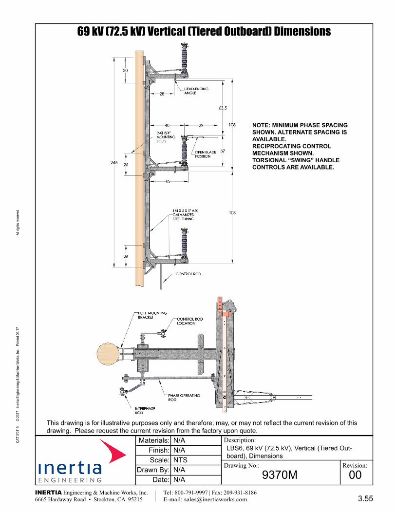
69 kV (72.5 kV) Vertical (Tiered Outboard) Dimensions
9370M 00
N/A
N/A
N/ANTS
N/A
LBS6, 69 kV (72.5 kV), Vertical (Tiered Out-board), Dimensions
Materials:Finish:Scale:
Drawn By:Date:
NOTE: MINIMUM PHASE SPACING SHOWN . ALTERNATE SPACING IS AVAILABLE .RECIPROCATING CONTROL MECHANISM SHOWN . TORSIONAL “SWING” HANDLE CONTROLS ARE AVAILABLE .
3.55
CAT1
7011
9I
© 20
17 I
nertia
Eng
ineer
ing &
Mac
hine W
orks
, Inc.
Prin
ted 01
/17
All r
ights
rese
rved
Description:
Drawing No.: Revision:
This drawing is for illustrative purposes only and therefore; may, or may not reflect the current revision of this drawing. Please request the current revision from the factory upon quote.
INERTIA Engineering & Machine Works, Inc. Tel: 800-791-9997 | Fax: 209-931-8186 6665 Hardaway Road • Stockton, CA 95215 E-mail: [email protected]
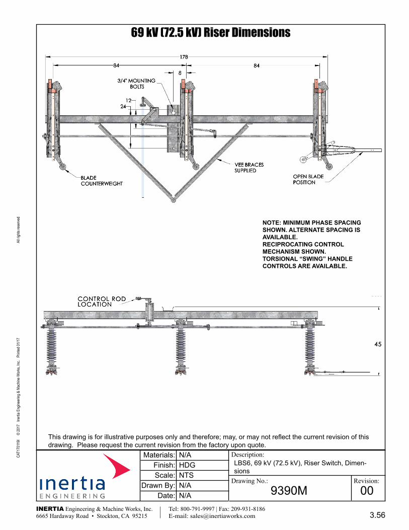
69 kV (72.5 kV) Riser Dimensions
9390M 00
N/A
N/A
HDGNTS
N/A
LBS6, 69 kV (72.5 kV), Riser Switch, Dimen-sions
Materials:Finish:Scale:
Drawn By:Date:
NOTE: MINIMUM PHASE SPACING SHOWN . ALTERNATE SPACING IS AVAILABLE .RECIPROCATING CONTROL MECHANISM SHOWN . TORSIONAL “SWING” HANDLE CONTROLS ARE AVAILABLE .
3.56

CAT1
7011
9I
© 20
17 I
nertia
Eng
ineer
ing &
Mac
hine W
orks
, Inc.
Prin
ted 01
/17
All r
ights
rese
rved
Description:
Drawing No.: Revision:
This drawing is for illustrative purposes only and therefore; may, or may not reflect the current revision of this drawing. Please request the current revision from the factory upon quote.
INERTIA Engineering & Machine Works, Inc. Tel: 800-791-9997 | Fax: 209-931-8186 6665 Hardaway Road • Stockton, CA 95215 E-mail: [email protected]
69 kV (72.5 kV) Vertical (Tiered Outboard) 2 Right 1 Left Dimensions
9515M 00
N/A
N/A
HDGNTS
N/A
LBS6, 69 kV (72.5 kV), Vertical (Tiered Out-board), 2 Right 1 Left, Switch Dimensions
Materials:Finish:Scale:
Drawn By:Date:
NOTE: MINIMUM PHASE SPACING SHOWN . ALTERNATE SPACING IS AVAILABLE .RECIPROCATING CONTROL MECHANISM SHOWN . TORSIONAL “SWING” HANDLE CONTROLS ARE AVAILABLE .
3.57